Embed Size (px)
Citation preview

INSTALLATION AND PROGRAMMING GUIDE
734 Weigand Interface Module

Digital Monitoring Products, Inc. | 734 Installation and Programming Guide a
About the 734 ............................................. 1Power Supply ......................................................... 1Zone Terminals ...................................................... 1Annunciators .......................................................... 1Indicator LEDs ....................................................... 1Form C Relay ......................................................... 2Programming Connection ................................ 2Keypad In and Out Connections ................... 2
PCB Features ...............................................3
Install the 734 .............................................4Mount the 734 ...................................................... 4Wire the Electronic Lock .................................. 5Isolation Relay ...................................................... 6Install the 333 Suppressor ............................... 7Wire the Zone Terminals ................................... 8Connect a Card Reader ....................................10Set the 734’s Address ....................................... 12
TABLE OF CONTENTSProgram the 734 ....................................... 15
Program Start Display ...................................... 15Initialization Option ........................................... 15Initialize Confirm Option .................................16Activate Zone 2 Bypass ...................................16zone 2 Bypass Time ........................................... 17Relock on zone 2 Change ............................... 17Activate zone 3 Request to Exit ...................18Zone 3 REX Strike Time ...................................19Activate On-board Speaker ...........................19Card Options ........................................................19
Custom Card Definitions ......................... 21Wiegand Code Length .....................................21Site Code Position and Length .....................21User Code Position and Length ...................22Require Site Code .............................................22Site Code Display ..............................................22Enter Site Code .................................................23Number of User Code Digits .........................23

b 734 Installation and Programming Guide | Digital Monitoring Products, Inc.
No Communication with Panel ....................24Remove Keypad .................................................25
Keypad Bus Wiring Specifications ........ 26
Compliance Listing Specifications ........27UL Commercial Fire ..........................................27UL Access Control .............................................27ULC Commercial Burglary (XR150/XR550 Series Panels) ......................27
Certifications .............................................28Underwriters Laboratory (UL Listed) ........28
International Certifications .................... 29Intertek (ETL) Listed ........................................29
Product Specifications ........................... 30
Accessories ................................................ 31Proximity Readers ..............................................31Proximity Credentials ........................................31
Digital Monitoring Products, Inc. | 734 Installation and Programming Guide 1
ANNUNCIATORSAn on-board programmable piezo provides local annunciation at the 734. You can also connect a variety of switched ground annunciators to the 734 for remote annunciation.
INDICATOR LEDSThe 734 provides three indicator LEDs. The red LED turns on for the same duration as the door strike relay. The yellow LED turns on for one second to indicate receipt of a valid Wiegand input. The green LED indicates that data is being sent to the panel.
The 734 Wiegand Interface Module allows you to use the powerful built-in access control capability of DMP Panels. DMP panels provide access control, arming, and disarming using proximity, mag-stripe, biometric or other Wiegand-output authentication devices.
Connect a 734 to a DMP panel’s keypad bus or AX-Bus™ to use the powerful built-in access control capability of DMP panels. The 734 includes the following features:
POWER SUPPLYThe 734 operates at 12/24VDC from the power supply supporting a door’s magnetic lock or door-strike. It also provides a 10 Amp Form C relay contact for lock control.
ZONE TERMINALSZones 1, 2, and 3 on the 734 can be programmed for a variety of burglary or access control applications. Zone 4 is a class B, style A circuit that may be programmed as a fire zone.
ABOUT THE 734
2 734 Installation and Programming Guide | Digital Monitoring Products, Inc.
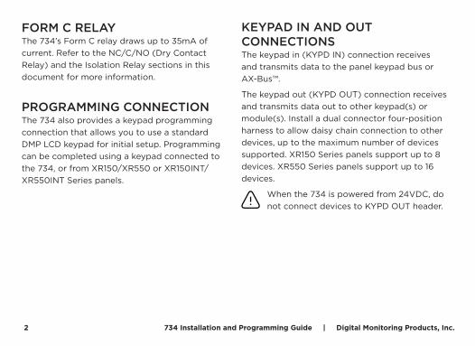
FORM C RELAYThe 734’s Form C relay draws up to 35mA of current. Refer to the NC/C/NO (Dry Contact Relay) and the Isolation Relay sections in this document for more information.
PROGRAMMING CONNECTIONThe 734 also provides a keypad programming connection that allows you to use a standard DMP LCD keypad for initial setup. Programming can be completed using a keypad connected to the 734, or from XR150/XR550 or XR150INT/XR550INT Series panels.
KEYPAD IN AND OUT CONNECTIONSThe keypad in (KYPD IN) connection receives and transmits data to the panel keypad bus or AX-Bus™.
The keypad out (KYPD OUT) connection receives and transmits data out to other keypad(s) or module(s). Install a dual connector four-position harness to allow daisy chain connection to other devices, up to the maximum number of devices supported. XR150 Series panels support up to 8 devices. XR550 Series panels support up to 16 devices.
When the 734 is powered from 24VDC, do not connect devices to KYPD OUT header.
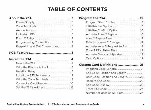
Digital Monitoring Products, Inc. | 734 Installation and Programming Guide 3RE
D
PROG
J2
RED
J5J4
KYPD OUT
S1
J3
J1
DATAXMT LED
WIEGANDREAD LED
RELAYON
NCCNO
GRNYELRED+ –
ON
Piezo
1 2 3 4 5 6 7 8 10 11 12 13 149
LC ASRED WHT GRN BLK Z1 Z2 Z3 Z4+ Z4–RA GND GND
KYPD IN RED
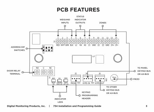
PCB FEATURES
DOOR RELAYTERMINAL
WEIGAND INPUTS
STATUS INDICATOR OUTPUTS ZONES
TO PANEL KEYPAD BUS OR AX-BUS
TO OTHER KEYPAD BUS OR AX-BUS
PIEZO
INDICATOR LEDS
KEYPAD PROGRAMMING HEADER
ADDRESS DIP SWITCHES

4 734 Installation and Programming Guide | Digital Monitoring Products, Inc.
INSTALL THE 734
The 734 comes in a high-impact plastic housing that you can mount directly to a wall, backboard, or other flat surface.
For easy installation, the back and ends of the 734 housing have wire entrances. The back also contains multiple screw holes that allow you to mount the 734 on a single-gang switch box. DMP recommends mounting the 734 near the protected door.
You can also mount the 734 in a panel enclosure by following these steps:
1. Remove the 734 PCB from the plastic housing.
2. Mount the plastic standoffs to the panel enclosure by pressing them into place.
3. Snap the 734 onto the standoffs.
1 MOUNT THE 734
Digital Monitoring Products, Inc. | 734 Installation and Programming Guide 5
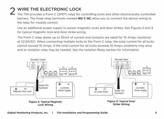
The 734 provides a Form C (SPDT) relay for controlling locks and other electronically-controlled barriers. The three relay terminals marked NO C NC allow you to connect the device wiring to the relay for module control.
Use an additional power supply to power magnetic locks and door strikes. See Figures 2 and 3 for typical magnetic lock and door strike wiring.
The Form C relay draws up to 35mA of current and contacts are rated for 10 Amps (resistive) at 12/24VDC. When connecting multiple locks to the Form C relay, the total current for all locks cannot exceed 10 Amps. If the total current for all locks exceeds 10 Amps, problems may arise and an isolation relay may be needed. See the Isolation Relay section for information.
2 WIRE THE ELECTRONIC LOCK
PROG
J2
RED REDKYPD IN
J4
J1
DATAXMT LED
WIEGANDREAD LED
RELAYON
NCCNO
GRNYELRED
Model 333Supressor
Normally Closed
–+Magnetic Door Lock
12/24VDCPower Supply
Figure 2: Typical Magnetic Lock Wiring
PROG
J2
RED
J1
DATAXMT LED
WIEGANDREAD LED
RELAYON
NCCNO
GRNYELRED
Model 333Supressor
Normally Open
–+DC Door Strike
12/24VDC Power Supply
Figure 3: Typical Door Strike Wiring
6 734 Installation and Programming Guide | Digital Monitoring Products, Inc.
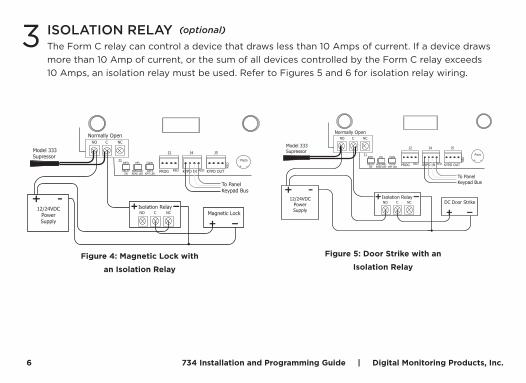
The Form C relay can control a device that draws less than 10 Amps of current. If a device draws more than 10 Amp of current, or the sum of all devices controlled by the Form C relay exceeds 10 Amps, an isolation relay must be used. Refer to Figures 5 and 6 for isolation relay wiring.
3 ISOLATION RELAY
RED
PROG
J2
RED
J5
REDKYPD IN
J4
KYPD OUT
J1
DATAXMT LED
WIEGANDREAD LED
RELAYON
NCCNO
GRNYELRED+ –
Piezo
Model 333Supressor
Normally Open
–+Magnetic Lock
–+Isolation Relay
To Panel Keypad Bus
12/24VDC PowerSupply
NCCNO
Figure 4: Magnetic Lock with
an Isolation Relay
RED
PROG
J2
RED
J5
REDKYPD IN
J4
KYPD OUT
J1
DATAXMT LED
WIEGANDREAD LED
RELAYON
NCCNO
GRNYELRED+ –
Piezo
Model 333Supressor
Normally Open
–+DC Door Strike
–+Isolation Relay
To Panel Keypad Bus
12/24VDC PowerSupply
NCCNO
Figure 5: Door Strike with an
Isolation Relay
(optional)

Digital Monitoring Products, Inc. | 734 Installation and Programming Guide 7
Use the included 333 suppressor with the 734 to suppress any surges caused by energizing a magnetic lock or door strike.
Install the 333 across the 734 C (common) and NO (normally open) or NC (normally closed) terminals.
If the device being controlled by the relay is connected to the NO and C terminals, install the suppressor on the NO and C terminals.
Conversely, if the device is connected to the NC and C terminals, install the 333 Suppressor on NC and C terminals.
The suppressor wire is non-polarized. Install the suppressor as shown in Figure 6.
4 INSTALL THE 333 SUPPRESSOR
RED
PROG
J2
734 Interface Module
RED
J5
REDKYPD IN
J4
KYPD OUT
J1
DATAXMT LED
WIEGANDREAD LED
RELAYON
NCCNO
GRNYELRED+ –
Piezo
Figure 6: 333 Suppressor
Installation on the 734
8 734 Installation and Programming Guide | Digital Monitoring Products, Inc.
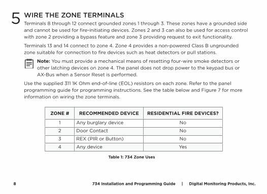
Terminals 8 through 12 connect grounded zones 1 through 3. These zones have a grounded side and cannot be used for fire-initiating devices. Zones 2 and 3 can also be used for access control with zone 2 providing a bypass feature and zone 3 providing request to exit functionality.
Terminals 13 and 14 connect to zone 4. Zone 4 provides a non-powered Class B ungrounded zone suitable for connection to fire devices such as heat detectors or pull stations.
Note: You must provide a mechanical means of resetting four-wire smoke detectors or other latching devices on zone 4. The panel does not drop power to the keypad bus or AX-Bus when a Sensor Reset is performed.
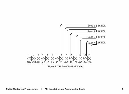
Use the supplied 311 1K Ohm end-of-line (EOL) resistors on each zone. Refer to the panel programming guide for programming instructions. See the table below and Figure 7 for more information on wiring the zone terminals.
5 WIRE THE ZONE TERMINALS
ZONE # RECOMMENDED DEVICE RESIDENTIAL FIRE DEVICES?
1 Any burglary device No
2 Door Contact No
3 REX (PIR or Button) No
4 Any device Yes
Table 1: 734 Zone Uses
Digital Monitoring Products, Inc. | 734 Installation and Programming Guide 9
Zone 1
Zone 2
Zone 3
Zone 4
1 2 3 4 5 6 7 8 10 11 12 13 149
LC ASRED WHT GRN BLK Z1 Z2 Z3 Z4+ Z4–RA GND GND
1K EOL
1K EOL
1K EOL
1K EOL
Figure 7: 734 Zone Terminal Wiring
10 734 Installation and Programming Guide | Digital Monitoring Products, Inc.
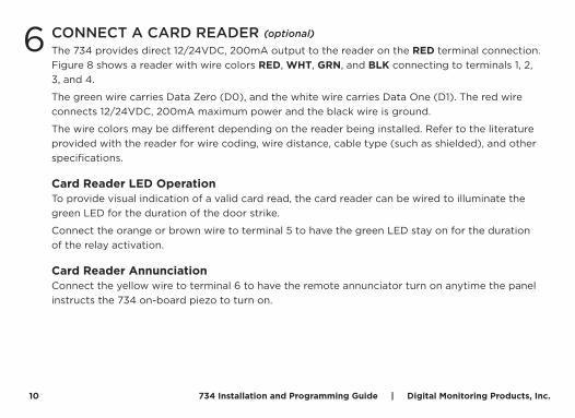
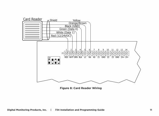
The 734 provides direct 12/24VDC, 200mA output to the reader on the RED terminal connection. Figure 8 shows a reader with wire colors RED, WHT, GRN, and BLK connecting to terminals 1, 2, 3, and 4.
The green wire carries Data Zero (D0), and the white wire carries Data One (D1). The red wire connects 12/24VDC, 200mA maximum power and the black wire is ground.
The wire colors may be different depending on the reader being installed. Refer to the literature provided with the reader for wire coding, wire distance, cable type (such as shielded), and other specifications.
Card Reader LED OperationTo provide visual indication of a valid card read, the card reader can be wired to illuminate the green LED for the duration of the door strike.
Connect the orange or brown wire to terminal 5 to have the green LED stay on for the duration of the relay activation.
Card Reader AnnunciationConnect the yellow wire to terminal 6 to have the remote annunciator turn on anytime the panel instructs the 734 on-board piezo to turn on.
6 CONNECT A CARD READER (optional)
Digital Monitoring Products, Inc. | 734 Installation and Programming Guide 11
Figure 8: Card Reader Wiring
1 2 3 4 5 6 7 8 10 11 12 13 149
LC ASRED WHT GRN BLK Z1 Z2 Z3 Z4+ Z4–RA GND GND
J3
ON
Card Reader
Red (12/24VDC)White (Data 1)
Black (GND)Green (Data 0)
ShieldOrange/Brown
Yellow
12 734 Installation and Programming Guide | Digital Monitoring Products, Inc.
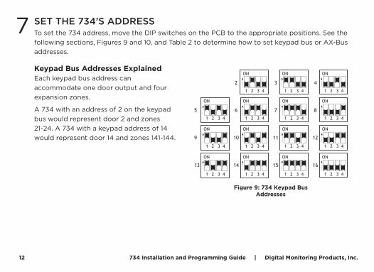
To set the 734 address, move the DIP switches on the PCB to the appropriate positions. See the following sections, Figures 9 and 10, and Table 2 to determine how to set keypad bus or AX-Bus addresses.
7 SET THE 734’S ADDRESS
Keypad Bus Addresses ExplainedEach keypad bus address can accommodate one door output and four expansion zones.
A 734 with an address of 2 on the keypad bus would represent door 2 and zones 21-24. A 734 with a keypad address of 14 would represent door 14 and zones 141-144.
ON
1 2 3 4
ON
1 2 3 4
ON
1 2 3 4
ON
1 2 3 4
ON
1 2 3 4
ON
1 2 3 4
ON
1 2 3 4
ON
1 2 3 4
ON
1 2 3 4
ON
1 2 3 4
ON
1 2 3 4
ON
1 2 3 4
ON
1 2 3 4
ON
1 2 3 4
ON
1 2 3 4
2 3 4
5 6 7 8
9 10 11 12
13 14 15 16
Figure 9: 734 Keypad Bus Addresses
Digital Monitoring Products, Inc. | 734 Installation and Programming Guide 13
1 2 3 4
5 6 7 8
9 10 11 12
13 14 15 16
ON
1 2 3 4
ON
1 2 3 4
ON
1 2 3 4
ON
1 2 3 4
ON
1 2 3 4
ON
1 2 3 4
ON
1 2 3 4
ON
1 2 3 4
ON
1 2 3 4
ON
1 2 3 4
ON
1 2 3 4
ON
1 2 3 4
ON
1 2 3 4
ON
1 2 3 4
ON
1 2 3 4
ON
1 2 3 4
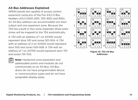
Figure 10: 734 AX-Bus Addresses
AX-Bus Addresses ExplainedXR550 panels are capable of access control expansion using any of the five AX/LX-Bus headers (AX/LX500, 600, 700, 800, and 900). An AX-Bus address can accommodate one door output and one expansion zone. Because the 734 has a built-in four-zone expander, three extra zones will be mapped to the 734 automatically.
A 734 with an address of 1 on AX500 would represent door 501 and zones 501-504. A 734 with an address of 2 on AX500 would represent door 505 and zones 505-508. A 734 with an address of 1 on AX700 would represent door 701 and zones 701-704.
Note: Hardwired zone expanders and addressable points and modules do not communicate on an AX-Bus. AX-Bus doors do not have programmable device or communication types and do not have assignable display areas.
14 734 Installation and Programming Guide | Digital Monitoring Products, Inc.
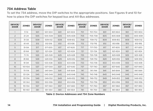
734 Address TableTo set the 734 address, move the DIP switches to the appropriate positions. See Figures 9 and 10 for how to place the DIP switches for keypad bus and AX-Bus addresses.
Table 2: Device Addresses and 734 Zone Numbers
DEVICE/DOOR ZONES DEVICE/
DOOR ZONES DEVICE/DOOR ZONES DEVICE/
DOOR ZONES DEVICE/DOOR ZONES DEVICE/
DOOR ZONES
1 11-14 501 501-504 601 601-604 701 701-704 801 801-804 901 901-904
2 21-24 505 505-508 605 605-608 705 705-708 805 805-808 905 905-908
3 31-34 509 509-512 609 609-612 709 709-712 809 809-812 909 909-512
4 41-44 513 513-516 613 613-616 713 713-716 813 813-816 913 913-916
5 51-54 517 517-520 617 617-620 717 717-720 817 817-820 917 917-920
6 61-64 521 521-524 621 621-624 721 721-724 821 821-824 921 921-924
7 71-74 525 525-528 625 625-628 725 725-728 825 825-828 925 925-928
8 81-84 529 529-532 629 629-632 729 729-732 829 829-832 929 929-932
9 91-94 533 533-536 633 633-636 733 733-736 833 833-836 933 933-936
10 101-104 537 537-540 637 637-640 737 737-740 837 837-840 937 937-940
11 111-114 541 541-544 641 641-644 741 741-744 841 841-844 941 941-944
12 121-124 545 545-548 645 645-648 745 745-748 845 845-848 945 945-948
13 131-134 549 549-552 649 649-652 749 749-752 849 849-852 949 949-952
14 141-144 553 553-556 653 653-656 753 753-756 853 853-856 953 953-956
15 151-154 557 557-560 657 657-660 757 757-760 857 857-860 957 957-960
16 161-164 561 561-564 661 661-664 761 761-764 861 861-864 961 961-964
Digital Monitoring Products, Inc. | 734 Installation and Programming Guide 15
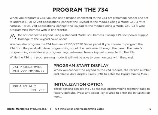
PROGRAM THE 734When you program a 734, you can use a keypad connected to the 734 programming header and set to address 1. For 12 Volt applications, connect the keypad to the module using a Model 330 4-wire harness. For 24 Volt applications, connect the keypad to the module using a Model 330-24 4-wire programming harness with in-line resistor.
Do not connect a keypad using a standard Model 330 harness if using a 24 volt power supply! Damage to the keypad could occur.
You can also program the 734 from an XR150/XR550 Series panel. If you choose to program the 734 from the panel, all future programming should be performed through the panel. The panel’s programming overrides any programming performed from a keypad connected to the 734.
While the 734 is in programming mode, it will not be able to communicate with the panel.
PROGRAM START DISPLAYWhen you connect the keypad to the 734 module, the version number and release date display. Press CMD to enter the Programming Menu.
INITIALIZATION OPTIONThese options can set the 734 module programming memory back to factory defaults. Press any select key or area to enter the initialization menu.
734 PROGRAMMINGVER VVV MM/DD/YY
INITIALIZE ALL? NO YES
16 734 Installation and Programming Guide | Digital Monitoring Products, Inc.
INITIALIZE CONFIRM OPTIONAfter selecting YES to clear the Access Options, the 734 displays SURE? YES NO for confirmation to clear the memory. This is a safeguard against accidentally erasing the programming. No memory is cleared from the programming until you answer YES to the SURE? option. Selecting NO leaves communication options unchanged.
ACTIVATE ZONE 2 BYPASSSelect YES to activate the zone 2 bypass operation. Selecting NO allows standard zone operation on zone 2. The default is NO.
If the door being released by the 734 module is protected (contact installed), a programmable bypass entry/exit timer can be provided by connecting its contact wiring to the 734 module zone 2. When the on-board Form C relay activates and the user opens the door connected to zone 2, the zone is delayed for the number of seconds programmed in ZONE 2 BYPASS TIME allowing the user to enter/exit during an armed period.
If zone 2 does not restore (door closed) within the programmed time, the piezo sounds every other second during the last ten seconds. If zone 2 restores prior to the end of the programmed time, the piezo silences. If the zone does not restore before the programmed time, the 734 ends the bypass and indicates the open or short zone condition to the panel.
ARE YOU SURE? YES NO
ACTIVATE ZONE 2BYPASS? NO YES
Digital Monitoring Products, Inc. | 734 Installation and Programming Guide 17
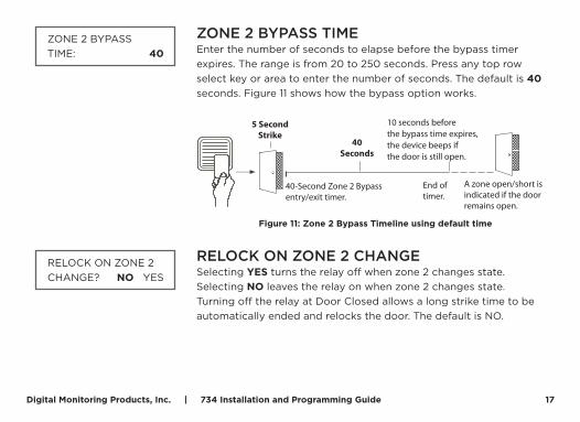
ZONE 2 BYPASS TIMEEnter the number of seconds to elapse before the bypass timer expires. The range is from 20 to 250 seconds. Press any top row select key or area to enter the number of seconds. The default is 40 seconds. Figure 11 shows how the bypass option works.
RELOCK ON ZONE 2 CHANGESelecting YES turns the relay off when zone 2 changes state. Selecting NO leaves the relay on when zone 2 changes state. Turning off the relay at Door Closed allows a long strike time to be automatically ended and relocks the door. The default is NO.
ZONE 2 BYPASSTIME: 40
5 SecondStrike
40-Second Zone 2 Bypassentry/exit timer.
10 seconds beforethe bypass time expires,the device beeps ifthe door is still open.
End of timer.
40Seconds
A zone open/short is indicated if the door remains open.
Figure 11: Zone 2 Bypass Timeline using default time
RELOCK ON ZONE 2CHANGE? NO YES
18 734 Installation and Programming Guide | Digital Monitoring Products, Inc.
ACTIVATE ZONE 3 REQUEST TO EXITSelecting YES activates the zone 3 Request to Exit (REX) option. Selecting NO allows standard zone operation on zone 3. Default setting is NO.
Connect a motion sensing device or a mechanical switch to zone 3 to provide REX capability to the system.
When zone 3 shorts, the on-board Form C relay activates for the programmed number of seconds (see zone 3 REX Strike Time). During this time, the user can open the protected door to start the programmed zone 2 bypass entry/exit timer. After the programmed number of seconds, the relay restores the door to its locked state.
The 734 module provides a bypass-only option for REX on zone 3. When zone 3 OPENS from a NORMAL state, only a bypass occurs: the on-board relay does not activate. This bypass-only option uses two methods of REX.
The first REX device provides the programmed bypass entry/exit timer. The second REX unlocks the door.
ACTIVATE ZONE 3REX? NO YES
Digital Monitoring Products, Inc. | 734 Installation and Programming Guide 19
ZONE 3 REX STRIKE TIMEEnter the number of REX seconds to elapse. Range is from 5 to 250 seconds. Press any select key or area to enter the number of seconds. The default is 5 seconds.
ACTIVATE ON-BOARD SPEAKERSelect YES to enable the onboard piezo for local annunciation, such as alarm and trouble annunciations. Select NO to turn the speaker off for all operations. This does not affect remote annunciator open collector (RA) operation. The default is NO.
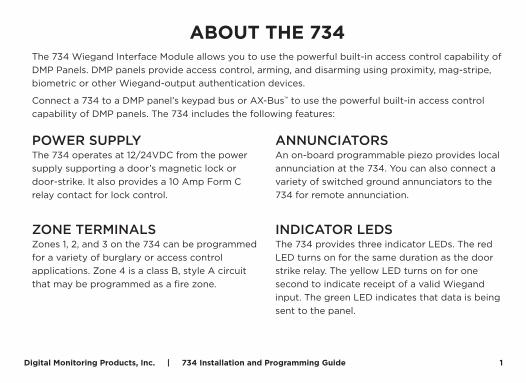
CARD OPTIONSTypically, an access card contains data bits for a site code, a user code, and start/stop/parity bits. The starting position location and code length must be determined and programmed into the 734 Module. Select DMP to indicate the reader sends a 26-45 bit data string. To select the DMP option, press the first select key or area under DMP. Default is DMP.
Select CUSTOM if using a non-DMP card.
Select ANY to allow all card reads to activate the door strike relay.
ZN 3 REX STRIKETIME: 5
ACTIVATE ONBOARDSPEAKER? NO YES
CARD OPTIONS:DMP
CARD OPTIONS:DMP CUSTOM ANY
20 734 Installation and Programming Guide | Digital Monitoring Products, Inc.
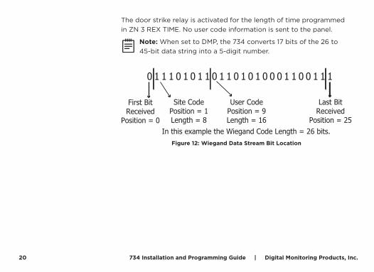
The door strike relay is activated for the length of time programmed in ZN 3 REX TIME. No user code information is sent to the panel.
Note: When set to DMP, the 734 converts 17 bits of the 26 to 45-bit data string into a 5-digit number.
0 1 1 1 0 1 0 1 1 0 1 1 0 1 0 1 0 0 0 1 1 0 0 1 1 1
First BitReceived
Position = 0
Site CodePosition = 1Length = 8
User CodePosition = 9Length = 16
Last BitReceived
Position = 25In this example the Wiegand Code Length = 26 bits.
Figure 12: Wiegand Data Stream Bit Location
Digital Monitoring Products, Inc. | 734 Installation and Programming Guide 21
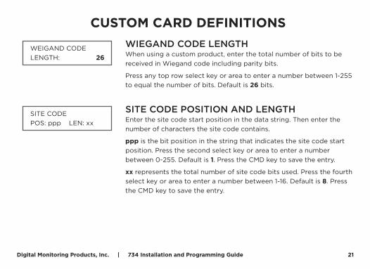
CUSTOM CARD DEFINITIONSWIEGAND CODE LENGTHWhen using a custom product, enter the total number of bits to be received in Wiegand code including parity bits.
Press any top row select key or area to enter a number between 1-255 to equal the number of bits. Default is 26 bits.
SITE CODE POSITION AND LENGTHEnter the site code start position in the data string. Then enter the number of characters the site code contains.
ppp is the bit position in the string that indicates the site code start position. Press the second select key or area to enter a number between 0-255. Default is 1. Press the CMD key to save the entry.
xx represents the total number of site code bits used. Press the fourth select key or area to enter a number between 1-16. Default is 8. Press the CMD key to save the entry.
WEIGAND CODELENGTH: 26
SITE CODEPOS: ppp LEN: xx
22 734 Installation and Programming Guide | Digital Monitoring Products, Inc.
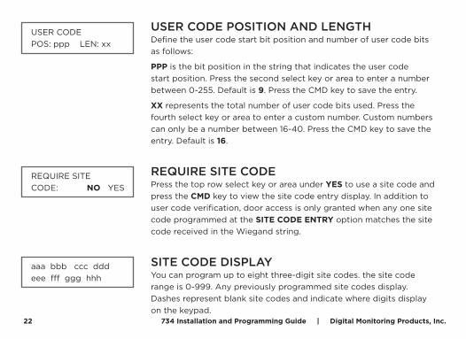
USER CODE POSITION AND LENGTHDefine the user code start bit position and number of user code bits as follows:
PPP is the bit position in the string that indicates the user code start position. Press the second select key or area to enter a number between 0-255. Default is 9. Press the CMD key to save the entry.
XX represents the total number of user code bits used. Press the fourth select key or area to enter a custom number. Custom numbers can only be a number between 16-40. Press the CMD key to save the entry. Default is 16.
REQUIRE SITE CODEPress the top row select key or area under YES to use a site code and press the CMD key to view the site code entry display. In addition to user code verification, door access is only granted when any one site code programmed at the SITE CODE ENTRY option matches the site code received in the Wiegand string.
SITE CODE DISPLAYYou can program up to eight three-digit site codes. the site code range is 0-999. Any previously programmed site codes display. Dashes represent blank site codes and indicate where digits display on the keypad.
USER CODEPOS: ppp LEN: xx
REQUIRE SITECODE: NO YES
aaa bbb ccc dddeee fff ggg hhh
Digital Monitoring Products, Inc. | 734 Installation and Programming Guide 23
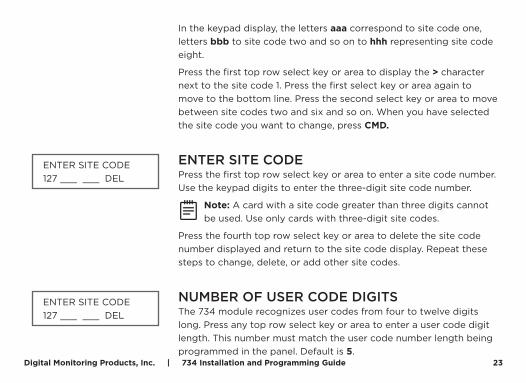
In the keypad display, the letters aaa correspond to site code one, letters bbb to site code two and so on to hhh representing site code eight.
Press the first top row select key or area to display the > character next to the site code 1. Press the first select key or area again to move to the bottom line. Press the second select key or area to move between site codes two and six and so on. When you have selected the site code you want to change, press CMD.
ENTER SITE CODE Press the first top row select key or area to enter a site code number. Use the keypad digits to enter the three-digit site code number.
Note: A card with a site code greater than three digits cannot be used. Use only cards with three-digit site codes.
Press the fourth top row select key or area to delete the site code number displayed and return to the site code display. Repeat these steps to change, delete, or add other site codes.
NUMBER OF USER CODE DIGITSThe 734 module recognizes user codes from four to twelve digits long. Press any top row select key or area to enter a user code digit length. This number must match the user code number length being programmed in the panel. Default is 5.
ENTER SITE CODE127 ___ ___ DEL
ENTER SITE CODE127 ___ ___ DEL
24 734 Installation and Programming Guide | Digital Monitoring Products, Inc.
All bits are read and converted into a decimal number string. The number string is left padded with ‘0’ if needed for long user code lengths. When selecting ‘4’ the right digit is dropped and the next four sent.
Example: # decoded 1234567
10 digits 0001234567
5 digits 34567
4 digits 3456
NO COMMUNICATION WITH PANELThis option defines the relay action when communication with the panel has not occurred for five seconds. Default is OFF. Press any top row select key or area to change the default relay action.
Choose the action required when the 734 cannot establish communication with the panel:
Press the first select key or area to choose OFF (Relay Always Off) — The relay does not turn on when any Wiegand string is received. OFF does not affect any REX operation. If communication is lost during a door strike, relay remains on for the door strike duration, but turns off at the end of the door strike timer.
Press the second select key or area to choose SITE (Accept Site
NO COMM WITH PNLOFF
NO COMM WITH PNLOFF SITE ANY ON
Digital Monitoring Products, Inc. | 734 Installation and Programming Guide 25
Code) — Door access is granted when the Wiegand site code string received matches any site code programmed at SITE CODE 1-8. For details refer back to the REQUIRE SITE CODE option.
Press the third select key or area to choose ANY (Any Wiegand Read) — Access is granted when any Wiegand string is received.
Press the fourth select key or area to choose ON (Relay Always On) — The relay is always on.
Press the CMD key to display the next action.
Press the first select key or area to choose LAST (Keep Last State) — The relay remains in the same state and does not change when communication is lost.
REMOVE KEYPADThe REMOVE KEYPAD option continually displays with no time out while the keypad remains connected to the 734 module after programming is finished. After five seconds the 734 module piezo continually sounds if the keypad remains connected and programming is finished. Remove the keypad harness to disconnect the keypad from the 734 module and silence the alarm.
NO COMM WITH PNLLAST
REMOVE KEYPAD

26 734 Installation and Programming Guide | Digital Monitoring Products, Inc.
Refer to the following Keypad bus/AX-Bus/LX-Bus wiring specifications.
▸ DMP recommends using 18 or 22-gauge unshielded wire for all keypad and AX-Bus/LX-Bus circuits. Do not use twisted pair or shielded wire for AX-Bus/LX-Bus and keypad bus data circuits. All 22-gauge wire must be connected to a power-limited circuit and jacket wrapped.
▸ On keypad bus circuits, to maintain auxiliary power integrity when using 22-gauge wire do not exceed 500 feet. When using 18-gauge wire do not exceed 1,000 feet. To increase the wire length or to add devices, install an additional power supply that is listed for Fire Protective Signaling, power limited, and regulated (12/24VDC nominal) with battery backup.
Note: Each panel allows a specific number of supervised keypads. Add additional keypads in the unsupervised mode.
▸ Maximum distance for any one bus circuit (length of wire) is 2,500 feet regardless of the wire gauge. This distance can be in the form of one long wire run or multiple branches with all wiring totaling no more than 2,500 feet. As wire distance from the panel increases, DC voltage on the wire decreases. Maximum number of AX-Bus/LX-Bus devices per 2,500 feet circuit is 40 feet.
▸ Maximum voltage drop between the panel (or auxiliary power supply) and any device is 2.0VDC. If the voltage at any device is less than the required level, add an auxiliary power supply at the end of the circuit. When voltage is too low, the devices cannot operate properly.
For additional information refer to the panel's Installation Guide, the 710 Installation Sheet (LT-0310), and/or the LX-Bus/Keypad Bus Wiring Application Note (LT-2031).
KEYPAD BUS WIRING SPECIFICATIONS

Digital Monitoring Products, Inc. | 734 Installation and Programming Guide 27
COMPLIANCE LISTING SPECIFICATIONSUL COMMERCIAL FIREThe 734 Interface Module must be used in conjunction with at least one DMP 630F keypad.
Any Auxiliary Power Supplies must be regulated, power limited, and listed for Fire Protective Signaling Service.
UL ACCESS CONTROLThe access relay must be configured as fail-safe or fail-secure as determined by the local Authority Having Jurisdiction (AHJ). This system is not intended to be used in place of listed panic hardware.
The power supply must be a listed commercial burglary/household fire, power limited, Class 2 with a compatible voltage range for the product. The 734 requires a 12 or 24VDC power source.
ULC COMMERCIAL BURGLARY (XR150/XR550 SERIES PANELS)When using the zones of the 734 in a listed application, place the module in a listed enclosure and connect a DMP Model 307 Clip-on Tamper Switch to the enclosure programmed as a 24-Hour zone.
The 734 Access Control features have not been investigated by ULC.
The 734 zones can be used in a Low Risk application. For Medium or High Risk applications, refer to the Dual Zone Protection diagram in the XR150/XR550 Canadian installation guide.
28 734 Installation and Programming Guide | Digital Monitoring Products, Inc.
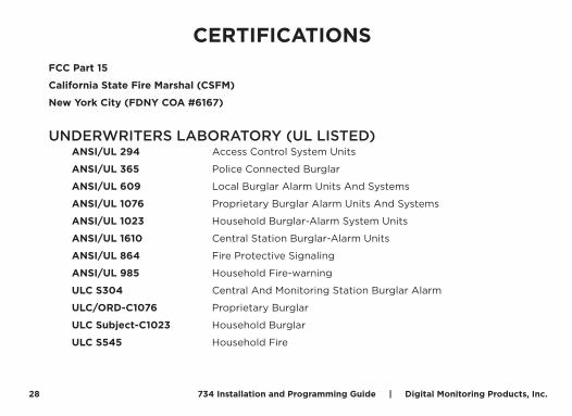
CERTIFICATIONSFCC Part 15
California State Fire Marshal (CSFM)
New York City (FDNY COA #6167)
UNDERWRITERS LABORATORY (UL LISTED) ANSI/UL 294 Access Control System Units
ANSI/UL 365 Police Connected Burglar
ANSI/UL 609 Local Burglar Alarm Units And Systems
ANSI/UL 1076 Proprietary Burglar Alarm Units And Systems
ANSI/UL 1023 Household Burglar-Alarm System Units
ANSI/UL 1610 Central Station Burglar-Alarm Units
ANSI/UL 864 Fire Protective Signaling
ANSI/UL 985 Household Fire-warning
ULC S304 Central And Monitoring Station Burglar Alarm
ULC/ORD-C1076 Proprietary Burglar
ULC Subject-C1023 Household Burglar
ULC S545 Household Fire

Digital Monitoring Products, Inc. | 734 Installation and Programming Guide 29
INTERNATIONAL CERTIFICATIONSSecurity Grade: 3
Environmental Class: II
INTERTEK (ETL) LISTED EN 50130-4 EMC Product Family Standard: Immunity
Requirements for Componenets of Fire,
Intruder and Social Alarm Systems
EN 50130-5 Environmental Standards
EN 50131-1:2006+A1 Intrusion and Hold-up Systems
EN 50131-3:2009 Control and Indicating Equipment
EN 50133-1:1997 Access Control Systems
EN 61000-3-2 Limits - Limits for Harmonic Current Emissions (Equip.Input Current up to and Including 16 A per Phase) Includes A1 & A2 July 1, 2009
EN 61000-3-3 Limitations of Voltage Fluctuations & Flicker in Low-Voltage Supply Systems for Equip with Rated Current Less Than or Equal to 16 A per Phase & Not Subject to Conditional Connection
EN 61000-6-4 Generic Standards - Emissions Standard for Industrial Environments
30 734 Installation and Programming Guide | Digital Monitoring Products, Inc.
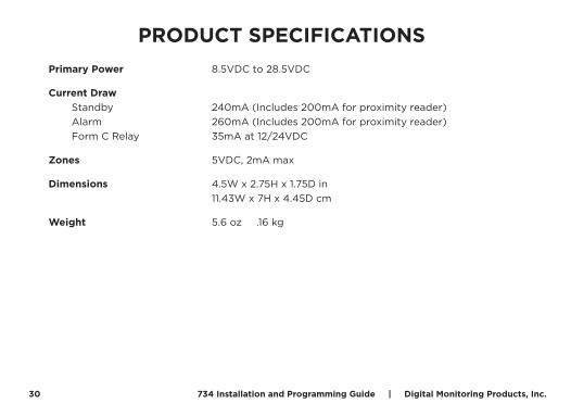
PRODUCT SPECIFICATIONSPrimary Power 8.5VDC to 28.5VDC
Current Draw Standby 240mA (Includes 200mA for proximity reader) Alarm 260mA (Includes 200mA for proximity reader) Form C Relay 35mA at 12/24VDC
Zones 5VDC, 2mA max
Dimensions 4.5W x 2.75H x 1.75D in 11.43W x 7H x 4.45D cm
Weight 5.6 oz .16 kg
Digital Monitoring Products, Inc. | 734 Installation and Programming Guide 31
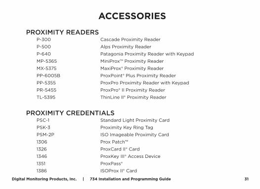
ACCESSORIES
PROXIMITY READERS P-300 Cascade Proximity Reader
P-500 Alps Proximity Reader
P-640 Patagonia Proximity Reader with Keypad
MP-5365 MiniProx™ Proximity Reader
MX-5375 MaxiProx® Proximity Reader
PP-6005B ProxPoint® Plus Proximity Reader
PP-5355 ProxPro Proximity Reader with Keypad
PR-5455 ProxPro® II Proximity Reader
TL-5395 ThinLine II® Proximity Reader
PROXIMITY CREDENTIALS PSC-1 Standard Light Proximity Card
PSK-3 Proximity Key Ring Tag
PSM-2P ISO Imageable Proximity Card
1306 Prox Patch™
1326 ProxCard II® Card
1346 ProxKey III® Access Device
1351 ProxPass®
1386 ISOProx II® Card
LT-0737 18072 1.07 © 2018 Digital Monitoring Products, Inc.