Embed Size (px)
Citation preview

7339913 (Rev. A 7/22/13)
How to install, operateand maintain your DemandControlled Water Softener
ModelsEP 7130 & EP 7140
Do not return water softener to store
Manufactured and warranted byEcodyne Water Systems
1890 Woodlane DriveWoodbury, MN 55125
Installation
and O
peratio
n Manual
If you have any questions or concerns wheninstalling, operating or maintaining your water
softener, call our toll free number:1-800-693-1138
Monday- Friday, 7 AM - 6 PM CST(in Canada please call 1-866-725-9662)
or visit www.ecopurewaterproducts.comWhen you call, please be prepared to providethe model and serial number of your product,found on the rating decal, typically located on
the rim below the salt lid hinges.
Systems tested and certified by NSF Internationalagainst NSF/ANSI Standard 44
for hardness reduction and efficiency, and certified to NSF/ANSI Standard 372.

2
TABLE OF CONTENTSPage
Specifications & Performance Claims . . . . . . . . . . . . . . . . . . . . . . . . . . . . . . . . . . . . . . . . . . . . . . . . . . . . . . . . . . . . 3Dimensions . . . . . . . . . . . . . . . . . . . . . . . . . . . . . . . . . . . . . . . . . . . . . . . . . . . . . . . . . . . . . . . . . . . . . . . . . . . . . . . . 4Safety Guides . . . . . . . . . . . . . . . . . . . . . . . . . . . . . . . . . . . . . . . . . . . . . . . . . . . . . . . . . . . . . . . . . . . . . . . . . . . . . . 4Inspect Shipment . . . . . . . . . . . . . . . . . . . . . . . . . . . . . . . . . . . . . . . . . . . . . . . . . . . . . . . . . . . . . . . . . . . . . . . . . . . . 5Water Conditioning Information . . . . . . . . . . . . . . . . . . . . . . . . . . . . . . . . . . . . . . . . . . . . . . . . . . . . . . . . . . . . . . . . . 5Installation Requirements . . . . . . . . . . . . . . . . . . . . . . . . . . . . . . . . . . . . . . . . . . . . . . . . . . . . . . . . . . . . . . . . . . . . 6-7Installation Instructions . . . . . . . . . . . . . . . . . . . . . . . . . . . . . . . . . . . . . . . . . . . . . . . . . . . . . . . . . . . . . . . . . . . . 8-11Programming the Water Softener . . . . . . . . . . . . . . . . . . . . . . . . . . . . . . . . . . . . . . . . . . . . . . . . . . . . . . . . . . . 12-13Customizing Features / Options . . . . . . . . . . . . . . . . . . . . . . . . . . . . . . . . . . . . . . . . . . . . . . . . . . . . . . . . . . . . . 14-15Routine Maintenance . . . . . . . . . . . . . . . . . . . . . . . . . . . . . . . . . . . . . . . . . . . . . . . . . . . . . . . . . . . . . . . . . . . . . 16-17Troubleshooting . . . . . . . . . . . . . . . . . . . . . . . . . . . . . . . . . . . . . . . . . . . . . . . . . . . . . . . . . . . . . . . . . . . . . . . . . 18-20Exploded View & Parts List . . . . . . . . . . . . . . . . . . . . . . . . . . . . . . . . . . . . . . . . . . . . . . . . . . . . . . . . . . . . . . . . 22-27
WATER SOFTENER WARRANTYWarrantor: Ecodyne Water Systems, 1890 Woodlane Drive, Woodbury, MN 55125
Warrantor guarantees, to the original owner, that:One Year Full Warranty:
● For a period of one (1) year from the date of purchase, all parts will be free from defects in materials and workmanshipand will perform their normal functions.
● For a period of one (1) year from the date of purchase, labor to repair or replace any part deemed to be defective inmaterials or workmanship, will be provided at no additional cost.
Limited Warranties:● For a period of ten (10) years from the date of purchase, the salt storage tank and fiberglass mineral tank will not rust,
corrode, leak, burst, or in any other manner, fail to perform its proper functions.● For a period of three (3) years from the date of purchase, the electronic control board will be free of defects in materi-
als and workmanship and will perform its normal functions.If, during such respective period, a part proves to be defective, Warrantor will ship a replacement part, directly to yourhome, without charge. After the first year, labor necessary to maintain this product is not covered by the product warranty.If you have questions regarding a warranted product, need assistance with installation or troubleshooting, wish to order apart or report a warranty issue, we are just a phone call away. SIMPLY DIAL 1-800-693-1138, Monday - Friday, 7 AM - 6PM CST, for assistance.
This water softener is manufactured byEcodyne Water Systems LLC, 1890 Woodlane Drive, Woodbury, MN 55125
General ProvisionsThe above warranties are effective provided the water softener is operated at water pressures not exceeding 125 psi, andat water temperatures not exceeding 120°F; provided further that the water softener is not subject to abuse, misuse, alter-ation, neglect, freezing, accident or negligence; and provided further that the water softener is not damaged as the result ofany unusual force of nature such as, but not limited to, flood, hurricane, tornado or earthquake.Warrantor is excused if failure to perform its warranty obligations is the result of strikes, government regulation, materialsshortages, or other circumstances beyond its control.*THERE ARE NO WARRANTIES ON THE WATER SOFTENER BEYOND THOSE SPECIFICALLY DESCRIBED ABOVE.ALL IMPLIED WARRANTIES, INCLUDING ANY IMPLIED WARRANTY OF MERCHANTABILITY OR OF FITNESS FORA PARTICULAR PURPOSE, ARE DISCLAIMED TO THE EXTENT THEY MIGHT EXTEND BEYOND THE ABOVE PERI-ODS. THE SOLE OBLIGATION OF WARRANTOR UNDER THESE WARRANTIES IS TO REPLACE OR REPAIR THECOMPONENT OR PART WHICH PROVES TO BE DEFECTIVE WITHIN THE SPECIFIED TIME PERIOD, AND WAR-RANTOR IS NOT LIABLE FOR CONSEQUENTIAL OR INCIDENTAL DAMAGES. NO WARRANTOR DEALER, AGENT,REPRESENTATIVE, OR OTHER PERSON IS AUTHORIZED TO EXTEND OR EXPAND THE WARRANTIES EXPRESS-LY DESCRIBED ABOVE.Some states do not allow limitations on how long an implied warranty lasts or exclusions or limitations of incidental or con-sequential damage, so the limitations and exclusions in this warranty may not apply to you. This warranty gives you spe-cific legal rights, and you may have other rights which vary from state to state. This warranty applies to consumer-ownedinstallations only.

3
Specifications & Performance Claims
Model EP 7130 Model EP 7140Model Code E7130 E7140
Rated Softening Capacity (Grains @ Salt Dose)14,700 @ 2.9 lbs.25,400 @ 8.0 lbs.
30,100 @ 13.1 lbs.11,900 @ 2.4 lbs.31,800 @ 9.1 lbs.
40,400 @ 15.8 lbs.Rated Efficiency (Grains/Pound of Salt @ Minimum Salt Dose) 5,060 @ 2.9 lbs. 4,960 @ 2.4 lbs.Water Used During Regeneration @ Minimum Salt Dose 2.3 gal. / 1,000 grains 3.4 gal. / 1,000 grainsTotal Water Used Per Regeneration @ Maximum Salt Dose 35.2 gallons 41.6 gallonsRated Service Flow Rate 7.5 gpm 9 gpmAmount of High Capacity Ion Exchange Resin .82 cu. ft. 1.16 cu. ft.Pressure Drop at Rated Service Flow 13.4 psig 9.1 psigWater Supply Max. Hardness 110 gpg 110 gpgWater Supply Max. Clear Water Iron 8 ppm* 10 ppm*Water Supply Pressure Limits (minimum / maximum) 20 - 125 psi (137.9 - 861.8 kPa)**Water Temperature Limits (minimum / maximum) 40 - 120 °FMinimum Water Supply Flow Rate 3 gpmMaximum Drain Flow Rate 2.0 gpmSalt Storage Capacity 220 lbs.
Questions? Call Toll Free 1-800-693-1138 Monday- Friday, 7 AM - 6 PM CSTor visit www.ecopurewaterproducts.com
When you call, please be prepared to provide the model and serial number,found on the rating decal, typically located on the rim below the salt lid hinges.
*Capacity to reduce clear water iron is substantiated by WQA test data. State of Wisconsin requires additionaltreatment if water supply contains clear water iron exceeding 5 ppm.
**Canada working pressure limits: 1.4 - 7.0 kg/cm2.These systems conform to NSF/ANSI 44 for the specific performance claims as verified and substantiated bytest data.Variable Salt Dose: The salt dose is selected by the electronic controls at regeneration time based on the
amount needed.
These models are efficiency rated. The efficiency rating is valid only at the minimum salt dose. These softenershave a demand initiated regeneration (D.I.R.) feature that complies with specific performance specifications intendedto minimize the amount of regenerant brine and water used in their operation.These softeners have a rated softener efficiency of not less than 3,350 grains of total hardness exchange per poundof salt (based on sodium chloride) and shall not deliver more salt than their listed rating or be operated at a sus-tained maximum service flow rate greater than their listed rating. These softeners have been proven to deliver softwater for at least ten continuous minutes at the rated service flow rate. The rated salt efficiency is measured by lab-oratory tests described in NSF/ANSI Standard 44. These tests represent the maximum possible efficiency that thesystem can achieve. Operational efficiency is the actual efficiency after the system has been installed. It is typicallyless than the rated efficiency, due to individual application factors including water hardness, water usage, and othercontaminants that reduce a softener's capacity.

4
Safety Guides
In the state of Massachusetts: The Commonwealth of Massachusetts plumbing code 248-CMR shallbe adhered to. A licensed plumber shall be used for this installation.
= The water softener requires a minimum water flow of 3 gallons per minute at the inlet. Maximum allowable inletwater pressure is 125 psi. If daytime pressure is over 80 psi, nighttime pressure may exceed the maximum. Usea pressure reducing valve if necessary (Adding a pressure reducing valve may reduce the flow). If your home isequipped with a back flow preventer, an expansion tank must be installed in accordance with local codes and laws.
= The water softener works on 24 volt, 60 Hz electrical power only, supplied by a direct plug-in transformer (includ-ed). Be sure to use the included transformer and plug it into a nominal 120V, 60 cycle household outlet that is ina dry location only, grounded and properly protected by an overcurrent device such as a circuit breaker or fuse.Power consumption is 13.5 W max imum and 1.0 W typical. If transformer is replaced, use only UL, CUL or CSAapproved Class 2 transformer with the following specifications:
§ Input: 120 VAC, 60 Hz, 13.5 W § Output Voltage: 24 VAC § Output Current: 400 mA= Do not use this system to treat water that is microbiologically unsafe or of unknown quality without adequate dis-
infection upstream or downstream of the system.European Directive 2002/96/EC requires all electrical and electronic equipment to be disposed of accord-ing to Waste Electrical and Electronic Equipment (WEEE) requirements. This directive or similar laws arein place nationally and can vary from region to region. Please refer to your state and local laws for properdisposal of this equipment.
In the state of California: You must turn the Salt Efficiency Feature setting to ON. This may initiatemore frequent recharges. However, it will operate at 4,000 grains per pound of salt or higher. To turnon the Salt Efficiency Feature, follow the instructions in the “Salt Efficiency” section of this manual.
Do not return the water softener to store.If you have any questions, or there are missing parts or damage, please call Toll Free 1-800-693-1138,Monday - Friday, 7 AM - 6 PM CST, or visit www.ecopurewaterproducts.comWhen you call, please be prepared to provide the model and serial number, found on the rating decal,typically located on the rim below the salt lid hinges.
Dimensions
44-3/4”A
B
21-1/4”
14-1/2”OUT
IN
IN – OUT
FIG. 1
MODEL DimensionA
DimensionB
EP 7130 37-7/8” 3-3/8”EP 7140 38-1/8” 3-3/4”

5
Packing List
Inspect Shipment
Water Conditioning InformationIRONIron in water can cause stains on clothing and plumb-ing fixtures. It can negatively affect the taste of food,drinking water, and other beverages. Iron in water ismeasured in parts per million (ppm). The total* ppm ofiron, and type or types*, is determined by chemicalanalysis. Four different types of iron in water are:= Ferrous (clear water) iron= Ferric (red water) iron= Bacterial and organically bound iron= Colloidal and inorganically bound iron (ferrous or
ferric)Ferrous (clear water) iron is soluble and dissolves inwater. This water softener will reduce moderateamounts of this type of iron (see specifications).**Ferrous (clear water) iron is usually detected by takinga sample of water in a clear bottle or glass.Immediately after taking, the sample is clear. As thewater sample stands, it gradually clouds and turnsslightly yellow or brown as air oxidizes the iron. Thisusually occurs in 15 to 30 minutes.When using the softener to reduce Ferrous (clearwater) iron, add 5 grains to the hardness setting forevery 1 ppm of Ferrous (clear water) iron. See "SetWater Hardness Number" section.Ferric (red water), and bacterial and organically boundirons are insoluble. This water softener will notremove ferric or bacterial iron. This iron is visible
immediately when drawn from a faucet because it hasoxidized before reaching the home. It appears assmall cloudy yellow, orange, or reddish suspendedparticles. After the water stands for a period of time,the particles settle to the bottom of the container.Generally these irons are removed from water by filtra-tion. Chlorination is also recommended for bacterialiron.Colloidal and inorganically bound iron is of ferric or fer-rous form that will not filter or exchange out of water.This water softener will not remove colloidal iron. Insome instances, treatment may improve colloidal ironwater. Colloidal iron water usually has a yellowappearance when drawn. After standing for severalhours, the color persists and the iron does not settle,but remains suspended in the water.SEDIMENTSediment is fine, foreign material particles suspendedin water. This water softener will not remove sedi-ment. This material is most often clay or silt. Extremeamounts of sediment may give the water a cloudyappearance. A sediment filter installed upstream of thewater softener normally corrects this situation.* Water may contain one or more of the four types of
iron and any combination of these. Total iron is thesum of the contents.
** Capacity to reduce clear water iron is substantiatedby WQA test data.
The parts required to assemble and install the watersoftener are included with the unit. Thoroughly checkthe water softener for possible shipping damage andparts loss. Also inspect and note any damage to theshipping carton.
Remove and discard (or recycle) all packing materials.To avoid loss of small parts, we suggest you keep thesmall parts in the parts bag until you are ready to usethem.
Ground ClampKit Bypass Valve
(Model EP 7140)Bypass Valve
(Model EP 7130) Drain HoseInstallationAdaptors
FIG. 2Adaptor ElbowHose Clamps Grommet O-rings (ModelEP 7140 only)
Water HardnessTest Strip
Clips
6
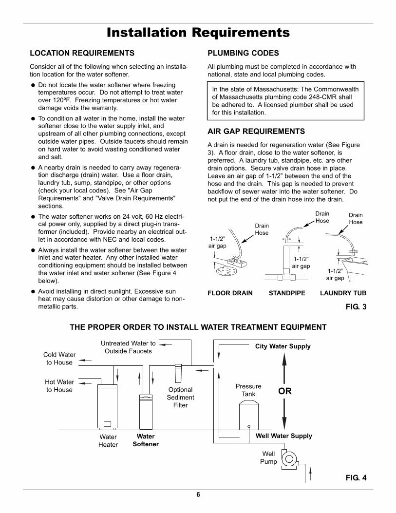
PLUMBING CODESAll plumbing must be completed in accordance withnational, state and local plumbing codes.
LAUNDRY TUBSTANDPIPE
1-1/2”air gap
FLOOR DRAIN
In the state of Massachusetts: The Commonwealthof Massachusetts plumbing code 248-CMR shallbe adhered to. A licensed plumber shall be usedfor this installation.
AIR GAP REQUIREMENTSA drain is needed for regeneration water (See Figure3). A floor drain, close to the water softener, ispreferred. A laundry tub, standpipe, etc. are otherdrain options. Secure valve drain hose in place.Leave an air gap of 1-1/2” between the end of thehose and the drain. This gap is needed to preventbackflow of sewer water into the water softener. Donot put the end of the drain hose into the drain.
FIG. 3
1-1/2”air gap
DrainHose
DrainHose
1-1/2”air gap
LOCATION REQUIREMENTSConsider all of the following when selecting an installa-tion location for the water softener.= Do not locate the water softener where freezing
temperatures occur. Do not attempt to treat waterover 120ºF. Freezing temperatures or hot waterdamage voids the warranty.
= To condition all water in the home, install the watersoftener close to the water supply inlet, andupstream of all other plumbing connections, exceptoutside water pipes. Outside faucets should remainon hard water to avoid wasting conditioned waterand salt.
= A nearby drain is needed to carry away regenera-tion discharge (drain) water. Use a floor drain,laundry tub, sump, standpipe, or other options(check your local codes). See "Air GapRequirements" and "Valve Drain Requirements"sections.
= The water softener works on 24 volt, 60 Hz electri-cal power only, supplied by a direct plug-in trans-former (included). Provide nearby an electrical out-let in accordance with NEC and local codes.
= Always install the water softener between the waterinlet and water heater. Any other installed waterconditioning equipment should be installed betweenthe water inlet and water softener (See Figure 4below).
= Avoid installing in direct sunlight. Excessive sunheat may cause distortion or other damage to non-metallic parts.
Installation Requirements
THE PROPER ORDER TO INSTALL WATER TREATMENT EQUIPMENT
FIG. 4
PressureTank
City Water Supply
Well Water Supply
WellPump
OROptionalSediment
Filter
WaterHeater
WaterSoftener
Untreated Water toOutside Faucets
Hot Waterto House
Cold Waterto House
DrainHose

7
Installation RequirementsVALVE DRAIN REQUIREMENTSUsing the flexible drain hose (included), measure andcut to the length needed. Flexible drain hose is notallowed in all localities (check your plumbing codes). Iflocal codes do not allow use of a flexible drain hose, arigid valve drain run must be used. Purchase a com-pression fitting (1/4 NPT x 1/2 in. minimum tube) and1/2" tubing from your local hardware store. Plumb arigid drain as needed (See Figure 6).NOTE: Avoid drain hose runs longer than 30 feet.
Avoid elevating the hose more than 8 feetabove the floor. Make the valve drain line asshort and direct as possible.
INLET / OUTLET PLUMBING OPTIONSAlways install either a single bypass valve (provided),as shown in Figure 7, or, if desired, parts for a 3 valvebypass system (not included) can be purchased andassembled, as shown in Figure 8. Bypass valvesallow you to turn off water to the softener for mainte-nance if needed, but still have water in house pipes.Pipe fittings must be 3/4” minimum.Use:= Copper pipe= Threaded pipe= PEX (Crosslinked Polyethylene) pipe= CPVC plastic pipe= Other pipe approved for use with potable waterIMPORTANT: Do not solder with plumbing attached to
installation adaptors and single bypassvalve. Soldering heat will damage theadaptors and valve.
FIG. 6
Clip
Barbs
1/4 NPTThreads
1/2” Outside Dia.Copper Tube(not included)
Compression Fitting.1/4 NPT x 1/2” O.D.Tube (not included)
Cut barbs from drain fit-ting (pull clip to remove
fitting from valve)
FIG. 7
FIG. 8
SINGLE BYPASS VALVEPull out for “Service”(Soft water)
Push in for“Bypass”
3 VALVE BYPASS
From WaterSoftener
To WaterSoftener
InletValve
OutletValve
BypassValve
FIG. 5
1/4” NPTThread Barbs for 3/8”
I.D. Tubing
Drain HoseHose Clamp

8
To OutsideFaucets
1-1/2”air gap
ConditionedWater
Hard Water
Main Water Pipe
Plug-inTransformer
Water SoftenerValve
ToController
Valve DrainElbow
Valve DrainHose*
*Do not connectthe water softenervalve drain tubingto the salt storagetank overflowhose. Floor Drain
OverflowDrain Elbow
Salt StorageTank OverflowHose*
Secure Valve Drain Hosein place over Floor Drain
NOTE: Water Softenershown with TopCover removed
Installation InstructionsTYPICAL INSTALLATION
FIG. 9
NOTE: See “Air Gap Requirements” section.NOTE: Water Softener shown with Salt Lid and
Top Cover removed
GroundClamp
Inlet
Outlet
Clips
GroundClamp
Pipe1” NPT SweatAdaptor (notincluded)
O-ring
SingleBypass Valve
LubricatedO-ring
1” NPTThreadedAdaptor
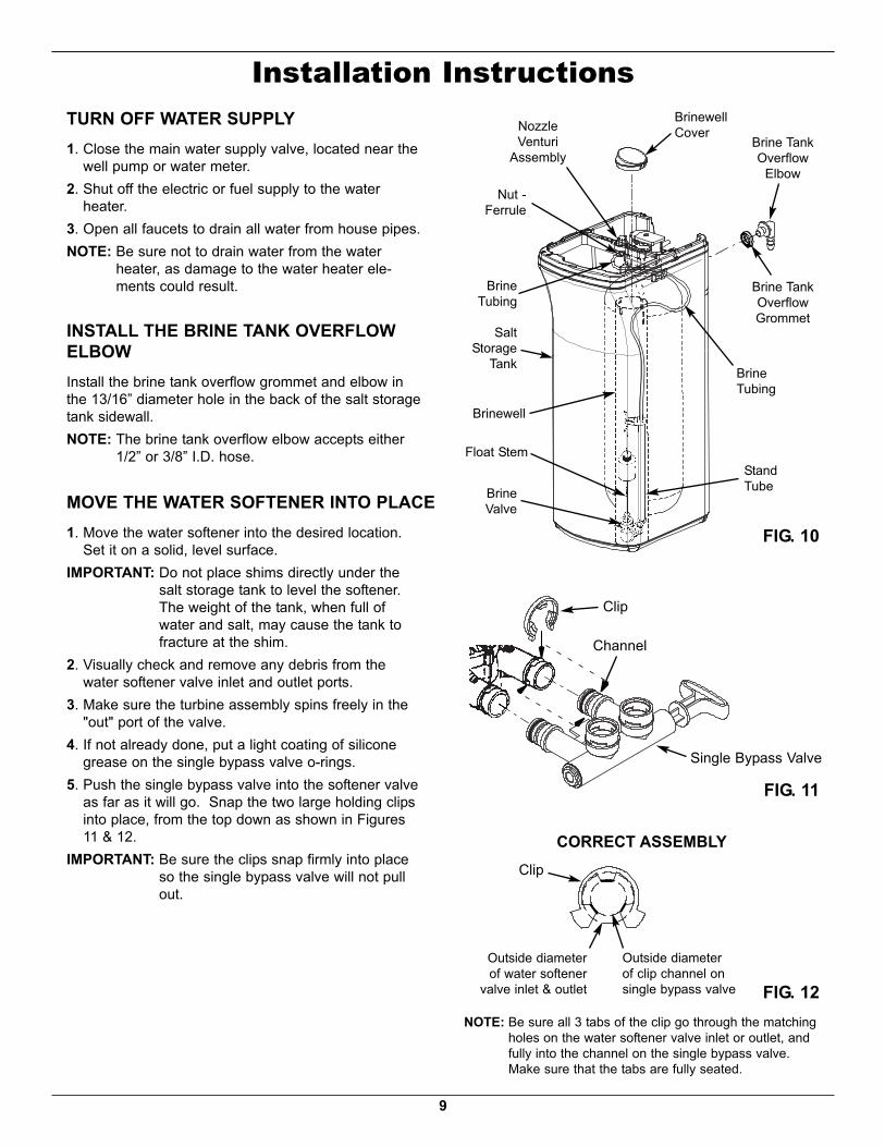
FIG. 10
Brine TankOverflow
Elbow
Brine TankOverflowGrommet
BrinewellCover
Brinewell
Float StemStandTubeBrine
Valve
SaltStorage
Tank BrineTubing
Nut -Ferrule
NozzleVenturi
Assembly
BrineTubing
9
Installation Instructions
1. Move the water softener into the desired location.Set it on a solid, level surface.
IMPORTANT: Do not place shims directly under thesalt storage tank to level the softener.The weight of the tank, when full ofwater and salt, may cause the tank tofracture at the shim.
2. Visually check and remove any debris from thewater softener valve inlet and outlet ports.
3. Make sure the turbine assembly spins freely in the"out" port of the valve.
4. If not already done, put a light coating of siliconegrease on the single bypass valve o-rings.
5. Push the single bypass valve into the softener valveas far as it will go. Snap the two large holding clipsinto place, from the top down as shown in Figures11 & 12.
IMPORTANT: Be sure the clips snap firmly into placeso the single bypass valve will not pullout.
TURN OFF WATER SUPPLY1. Close the main water supply valve, located near the
well pump or water meter.2. Shut off the electric or fuel supply to the water
heater.3. Open all faucets to drain all water from house pipes.NOTE: Be sure not to drain water from the water
heater, as damage to the water heater ele-ments could result.
INSTALL THE BRINE TANK OVERFLOWELBOWInstall the brine tank overflow grommet and elbow inthe 13/16” diameter hole in the back of the salt storagetank sidewall.NOTE: The brine tank overflow elbow accepts either
1/2” or 3/8” I.D. hose.
MOVE THE WATER SOFTENER INTO PLACE
FIG. 11
Clip
Channel
Single Bypass Valve
FIG. 12
CORRECT ASSEMBLYClip
Outside diameterof clip channel onsingle bypass valve
Outside diameterof water softener
valve inlet & outlet
NOTE: Be sure all 3 tabs of the clip go through the matchingholes on the water softener valve inlet or outlet, andfully into the channel on the single bypass valve.Make sure that the tabs are fully seated.
10
COMPLETE INLET AND OUTLET PLUMBINGMeasure, cut, and loosely assemble pipe and fittingsfrom the main water pipe to the inlet and outlet ports ofthe water softener valve. Be sure to keep fittings fullytogether, and pipes squared and straight.Be sure hard water supply pipe goes to the water sof-tener valve inlet side.NOTE: Inlet and outlet are marked on the water sof-
tener valve. Trace the water flow direction tobe sure hard water is to inlet.
IMPORTANT: Be sure to fit, align and support allplumbing to prevent putting stress onthe water softener valve inlet and outlet.Stress from misaligned or unsupportedplumbing may cause damage to thevalve.
Complete the inlet and outlet plumbing for the type ofpipe you will be using.
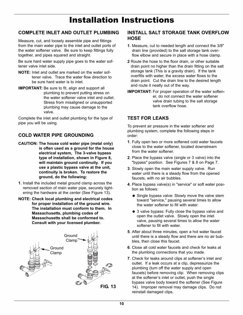
COLD WATER PIPE GROUNDINGCAUTION: The house cold water pipe (metal only)
is often used as a ground for the houseelectrical system, The 3-valve bypasstype of installation, shown in Figure 8,will maintain ground continuity. If youuse a plastic bypass valve at the unit,continuity is broken. To restore theground, do the following:
1. Install the included metal ground clamp across theremoved section of main water pipe, securely tight-ening the hardware at the center (See Figure 13).
NOTE: Check local plumbing and electrical codesfor proper installation of the ground wire.The installation must conform to them. InMassachusetts, plumbing codes ofMassachusetts shall be conformed to.Consult with your licensed plumber.
Installation Instructions
1. Measure, cut to needed length and connect the 3/8"drain line (provided) to the salt storage tank over-flow elbow and secure in place with a hose clamp.
2 Route the hose to the floor drain, or other suitabledrain point no higher than the drain fitting on the saltstorage tank (This is a gravity drain). If the tankoverfills with water, the excess water flows to thedrain point. Cut the drain line to the desired lengthand route it neatly out of the way.
IMPORTANT: For proper operation of the water soften-er, do not connect the water softenervalve drain tubing to the salt storagetank overflow hose.
TEST FOR LEAKSTo prevent air pressure in the water softener andplumbing system, complete the following steps inorder:1. Fully open two or more softened cold water faucets
close to the water softener, located downstreamfrom the water softener.
2. Place the bypass valve (single or 3 valve) into the"bypass" position. See Figures 7 & 8 on Page 7.
3. Slowly open the main water supply valve. Runwater until there is a steady flow from the openedfaucets, with no air bubbles.
4. Place bypass valve(s) in "service" or soft water posi-tion as follows:= Single bypass valve: Slowly move the valve stem
toward "service," pausing several times to allowthe water softener to fill with water.
= 3 valve bypass: Fully close the bypass valve andopen the outlet valve. Slowly open the inletvalve, pausing several times to allow the watersoftener to fill with water.
5. After about three minutes, open a hot water faucetuntil there is a steady flow and there are no air bub-bles, then close this faucet.
6. Close all cold water faucets and check for leaks atthe plumbing connections that you made.
7. Check for leaks around clips at softener’s inlet andoutlet. If a leak occurs at a clip, depressurize theplumbing (turn off the water supply and openfaucets) before removing clip. When removing clipsat the softener’s inlet or outlet, push the singlebypass valve body toward the softener (See Figure14). Improper removal may damage clips. Do notreinstall damaged clips.
INSTALL SALT STORAGE TANK OVERFLOWHOSE
FIG. 13
GroundClamp
GroundClamp

11
Installation Instructions
Questions? Call Toll Free 1-800-693-1138 Monday- Friday, 7 AM - 6 PM CSTor visit www.ecopurewaterproducts.com
When you call, please be prepared to provide the model and serial number,found on the rating decal, typically located on the rim below the salt lid hinges.
ADD WATER AND SALT TO THE SALTSTOR AGE TANK1. Using a container, add about three gallons of clean
water into the salt storage tank.2. Add salt to the storage tank. Use nugget, pellet or
coarse solar salts with less than 1% impurities.
PLUG IN THE WATER SOFTENERDuring installation, the water softener wiring may bemoved or jostled from place. Be sure all leadwire con-nectors are secure on the back of the electronic boardand be sure all wiring is away from the valve gear andmotor area, which rotates during regenerations.1. Plug the water softener into an electrical outlet that
is not controlled by a switch.NOTE: The water heater is filled with hard water and,
as hot water is used, it will refill with condi-tioned water. In a few days, the hot water willbe fully conditioned. To have fully conditionedhot water immediately, wait until the initialrecharge is over. Then, drain the water heater(following instructions for water heater) untilwater runs cold.
PROGRAM THE CONTROLLER1. Complete the Programming Steps on Pages 12 &
13.
SANITIZE THE WATER SOFTENER /SANITIZE AFTER SERVICECare is taken at the factory to keep your unit clean andsanitary. Materials used to make the unit will not infector contaminate your water supply, and will not causebacteria to form or grow. However, during shipping,storage, installation and operation, bacteria could getinto the unit. For this reason, sanitizing as follows issuggested* when installing.1. Slide open the salt lid, remove the brinewell cover
and pour about 3 oz. (6 tablespoons) of householdbleach into the softener brinewell. Replace thebrinewell cover.
2 Make sure the bypass valve(s) is in the “service”(open) position.
3 Start a recharge: Press the RECHARGE button andhold for 3 seconds, until “Recharge Now” begins toflash in the display. This recharge draws the sanitiz-ing bleach into and through the water softener. Anyair remaining in the unit is purged to the drain.
4. After the recharge has completed, fully open a coldwater faucet, downstream from the softener, andallow 50 gallons of water to pass through the sys-tem. This should take at least 20 minutes. Closethe faucet.
*Recommended by the Water Quality Association. On somewater supplies, the unit may need periodic disinfecting.
RESTART THE WATER HEATER1. Turn on the electricity or fuel supply to the water
heater and relight the pilot, if applicable.NOTE: The water heater is filled with hard water and,
as hot water is used, it refills with conditionedwater. In a few days, the hot water will be fullyconditioned. To have fully conditioned hotwater immediately, wait until the initial recharge(previous step) is over. Then, drain the waterheater (following instructions for water heater)until water runs cold.
FIG. 14
...depressurize theplumbing, then pushBypass Valve bodytoward softener
If removingclips...

UP button
DOWN buttonRECHARGE
button
SELECT / MENU button FIG. 15
12
Programming the Water Softener
FIG. 16
When the transformer is plugged into the electricaloutlet, a model code and a test number (example:J2.0), begin to flash in the faceplate display. Then,“12:00 PM” and the words “SET TIME" begin to flash.NOTE: If “- - - -” shows in the display, press the r
UP or s DOWN button until the model code(“E7130” for Model EP 7130 or “E7140” forModel EP 7140) shows in the display. Then,press the SELECT / MENU button to set, andchange to the flashing “SET TIME" display.
SET TIME OF DAYIf the words “SET TIME" do not show in the display,press the SELECT / MENU button until they do.1. Press the r UP or s DOWN buttons to set the
present time. Up moves the display ahead; downsets the time back. Be sure AM or PM is correct.
NOTE: Press buttons and quickly release to slowlyadvance the display. Hold the buttons downfor fast advance.
FIG. 17
SET WATER HARDNESS NUMBER1. Press the SELECT / MENU button once again to
display a flashing “25” and the words “SET HARD-NESS”.
2. Press the r UP or s DOWN buttons to set yourwater’s hardness number.NOTE: If your water supply contains iron, compen-
sate for it by adding to the water hardnessnumber. For example, assume your water is20 gpg hard and contains 2 ppm iron. Add 5to the hardness number for each 1 ppm ofiron. In this example, you would use 30 foryour hardness number.
20 gpg hardness2 ppm iron x 5 = 10 +10
(times) 30 HARDNESS NUMBER
NOTE: If you use potassium chloride (KCl) saltinstead of sodium chloride (NaCl) salt in thissoftener, increase the hardness setting by25%. For example, if you will be using KCland your water supply’s hardness is 20 gpg,set the softener to 25 gpg.
Low SaltIndicator LED
Displaypure

13
SET RECHARGE (REGENERATION) TIME1. Press the SELECT / MENU button once again to
display a flashing “2:00AM” and the words “SETRECHARGE TIME”. This is a good time for therecharge to start in most households, becausewater is not in use.
2. If you want to change the recharge start time,press the r UP or s DOWN buttons until thedesired time shows. Be sure AM or PM is correct.
FIG. 18
FIG. 19
Programming the Water SoftenerSET SALT LEVELThe water softener has a low salt indicator light toremind you to refill the storage tank with salt.NOTE: You must set salt level each time salt is added
to the water softener.To set this monitor system:1. Slide open the salt lid and level the salt in the stor-
age tank.2. The salt level decal, on the brinewell inside the
tank, has numbers from 0 to 8. Observe the high-est number the leveled salt is at, or closest to.
3. Press the SELECT / MENU button to display aflashing “OFF” and the words “SET SALT LEVEL”.
4. Press the r UP button until the number on thescreen corresponds to the salt level. At level 2 orbelow, the “Low Salt" LED indicator will flash. Ifyou wish to turn this feature off, press the sDOWN button past 0, and the word “OFF” flashesin the display.
5. Press the SELECT / MENU button once more tocomplete the initial programming. The current timeof day will show in the display.
FIG. 20

POWER OUTAGE MEMORYIf electrical power to the water softener is lost, “mem-ory'' built into the timer circuitry will keep all settingsfor several hours. While the power is out, the displayis blank and the water softener will not regenerate.When electrical power is restored, the following willoccur.You have to reset the present time only if the displayis flashing. The HARDNESS and RECHARGE TIMEnever require resetting unless a change is desired.Even if the clock is incorrect after a long power out-age, the softener operates as it should to keep yourwater soft. However, regenerations may occur at thewrong time of day until you reset the clock to the cor-rect time of day.NOTE: If the water softener was regenerating when
power was lost, it will now finish the cycle.
14
Customizing Features / OptionsRECHARGE NOWAt times of greater than normal water use, such aswhen you have guests, you could run out of condi-tioned water before the next scheduled recharge. Ifthis happens, you may want to initiate an immediateregeneration, as follows:1. Press and hold the RECHARGE button until the
words “RECHARGE NOW" flash in the display.
The softener enters the fill cycle of regeneration rightaway. “RECHARGE NOW” will flash during theregeneration. When completed (in about 2 hours),full water conditioning capacity is restored.NOTE: Avoid using hot water while the softener is
regenerating, because the water heater willrefill with bypass hard water.
RECHARGE TONIGHTIf you do not want to start an immediate recharge, butwould like an extra recharge at the next presetrecharge time, do the following to schedule arecharge:1. Press and release (do not hold) the RECHARGE
button.
The words “RECHARGE TONIGHT" flash in the dis-play, and the softener will recharge at the next presetrecharge time (If you decide to cancel the regenera-tion before it begins, press and release theRECHARGE button once more, and “RECHARGETONIGHT” will disappear from the display). Duringregeneration, the word “RECHARGE NOW" will flashin the screen. When completed, full water condition-ing capacity is restored.
FIG. 21RECHARGE NOW initiated
FIG. 22RECHARGE TONIGHT initiated

15
Customizing Features / OptionsSALT EFFICIENCYWhen this feature is ON, the water softener will oper-ate at salt efficiencies of 4000 grains of hardness perpound of salt or higher (May recharge more oftenusing smaller salt dosage and less water). The sof-tener is shipped with this feature set OFF.
1. Press and hold the SELECT / MENU button untilthe screen in Figure 23 is displayed. Once in thisdisplay, press the SELECT / MENU button onceand one of the two displays in Figure 24 is shown.
CALIFORNIA EFFICIENCY REQUIREMENT
FIG. 23
FIG. 242. Press the r UP or s DOWN buttons to set ON or
OFF. When set to ON, the efficiency icon will bedisplayed along the right side of the normal run dis-play.
FIG. 25
Displayed whenefficiency is set to ON
Efficiency Icon
Your EcoPure Water Softener has a “HighEfficiency” feature with an ON or OFF setting.This softener setting is shipped in the OFF posi-tion, which utilizes the maximum rated capacitywhile most often achieving maximum salt effi-ciencies. When installing this unit in the State ofCalifornia, you MUST turn this setting to the ONposition, which may initiate more frequentrecharges. However it will operate at 4000grains per pound of salt or higher.If you wish to turn the Salt Efficiency feature ON( icon will show in the display), follow theinstructions on this page.
Questions? Call Toll Free 1-800-693-1138 Monday- Friday, 7 AM - 6 PM CSTor visit www.ecopurwaterproducts.com
When you call, please be prepared to provide the model and serial number,found on the rating decal, typically located on the rim below the salt lid hinges.
16
FIG. 26
BroomHandle
PencilMark
1” - 2”SaltSaltBridgeWaterLevel
Push Tool intoSalt Bridge to
Break
FIG. 27
CapO-ring Seal
Screen SupportScreen
Gasket*Flow Plug (HVDC)
Housing
FerruleNut
Cone Screen*Flow Plug
*Install with letteredside up, concaveside down.
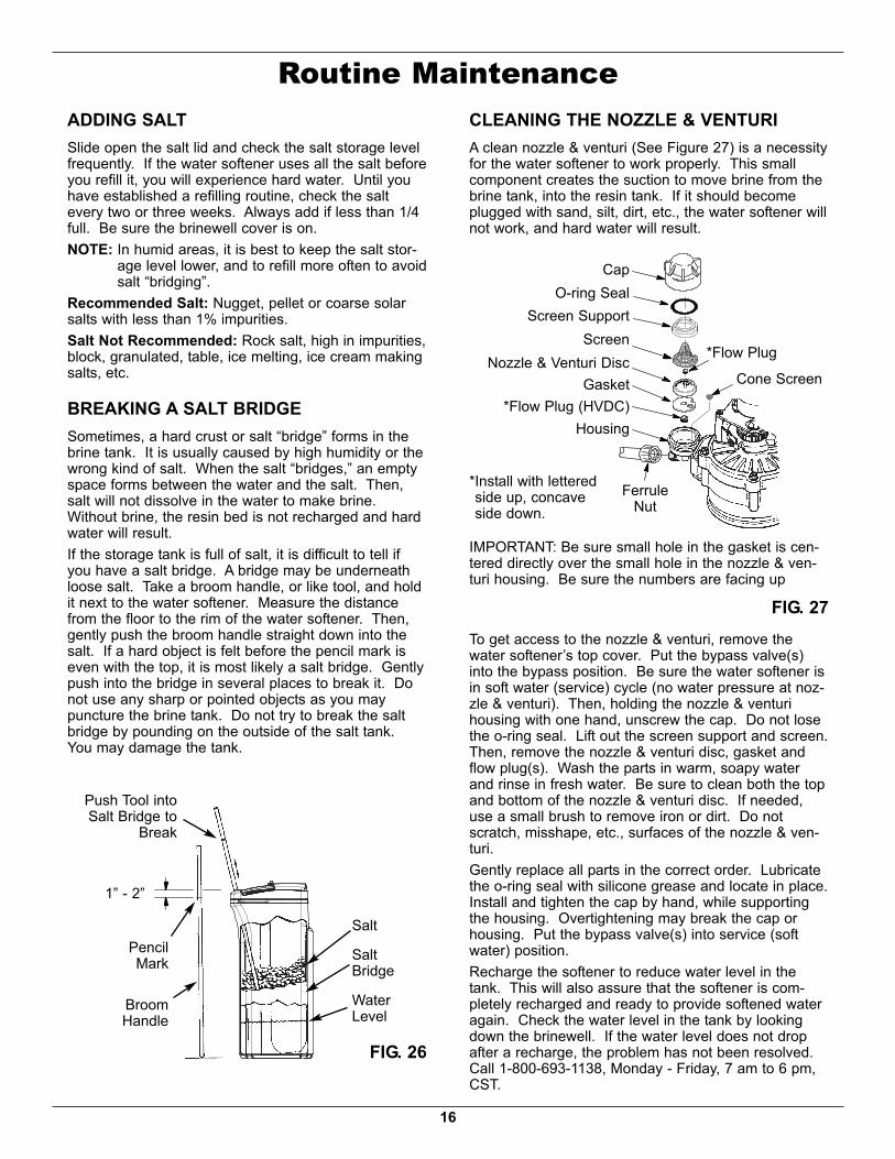
CLEANING THE NOZZLE & VENTURIA clean nozzle & venturi (See Figure 27) is a necessityfor the water softener to work properly. This smallcomponent creates the suction to move brine from thebrine tank, into the resin tank. If it should becomeplugged with sand, silt, dirt, etc., the water softener willnot work, and hard water will result.
Nozzle & Venturi Disc
IMPORTANT: Be sure small hole in the gasket is cen-tered directly over the small hole in the nozzle & ven-turi housing. Be sure the numbers are facing up
Routine MaintenanceADDING SALTSlide open the salt lid and check the salt storage levelfrequently. If the water softener uses all the salt beforeyou refill it, you will experience hard water. Until youhave established a refilling routine, check the saltevery two or three weeks. Always add if less than 1/4full. Be sure the brinewell cover is on.NOTE: In humid areas, it is best to keep the salt stor-
age level lower, and to refill more often to avoidsalt “bridging”.
Recommended Salt: Nugget, pellet or coarse solarsalts with less than 1% impurities.Salt Not Recommended: Rock salt, high in impurities,block, granulated, table, ice melting, ice cream makingsalts, etc.
BREAKING A SALT BRIDGESometimes, a hard crust or salt “bridge” forms in thebrine tank. It is usually caused by high humidity or thewrong kind of salt. When the salt “bridges,” an emptyspace forms between the water and the salt. Then,salt will not dissolve in the water to make brine.Without brine, the resin bed is not recharged and hardwater will result.If the storage tank is full of salt, it is difficult to tell ifyou have a salt bridge. A bridge may be underneathloose salt. Take a broom handle, or like tool, and holdit next to the water softener. Measure the distancefrom the floor to the rim of the water softener. Then,gently push the broom handle straight down into thesalt. If a hard object is felt before the pencil mark iseven with the top, it is most likely a salt bridge. Gentlypush into the bridge in several places to break it. Donot use any sharp or pointed objects as you maypuncture the brine tank. Do not try to break the saltbridge by pounding on the outside of the salt tank.You may damage the tank.
To get access to the nozzle & venturi, remove thewater softener’s top cover. Put the bypass valve(s)into the bypass position. Be sure the water softener isin soft water (service) cycle (no water pressure at noz-zle & venturi). Then, holding the nozzle & venturihousing with one hand, un screw the cap. Do not losethe o-ring seal. Lift out the screen support and screen.Then, remove the nozzle & venturi disc, gasket andflow plug(s). Wash the parts in warm, soapy waterand rinse in fresh water. Be sure to clean both the topand bottom of the nozzle & venturi disc. If needed,use a small brush to remove iron or dirt. Do notscratch, misshape, etc., surfaces of the nozzle & ven-turi.Gently replace all parts in the correct order. Lubricatethe o-ring seal with silicone grease and locate in place.Install and tighten the cap by hand, while supportingthe housing. Overtightening may break the cap orhousing. Put the bypass valve(s) into service (softwater) position.Recharge the softener to reduce water level in thetank. This will also assure that the softener is com-pletely recharged and ready to provide softened wateragain. Check the water level in the tank by lookingdown the brinewell. If the water level does not dropafter a recharge, the problem has not been resolved.Call 1-800-693-1138, Monday - Friday, 7 am to 6 pm,CST.
17
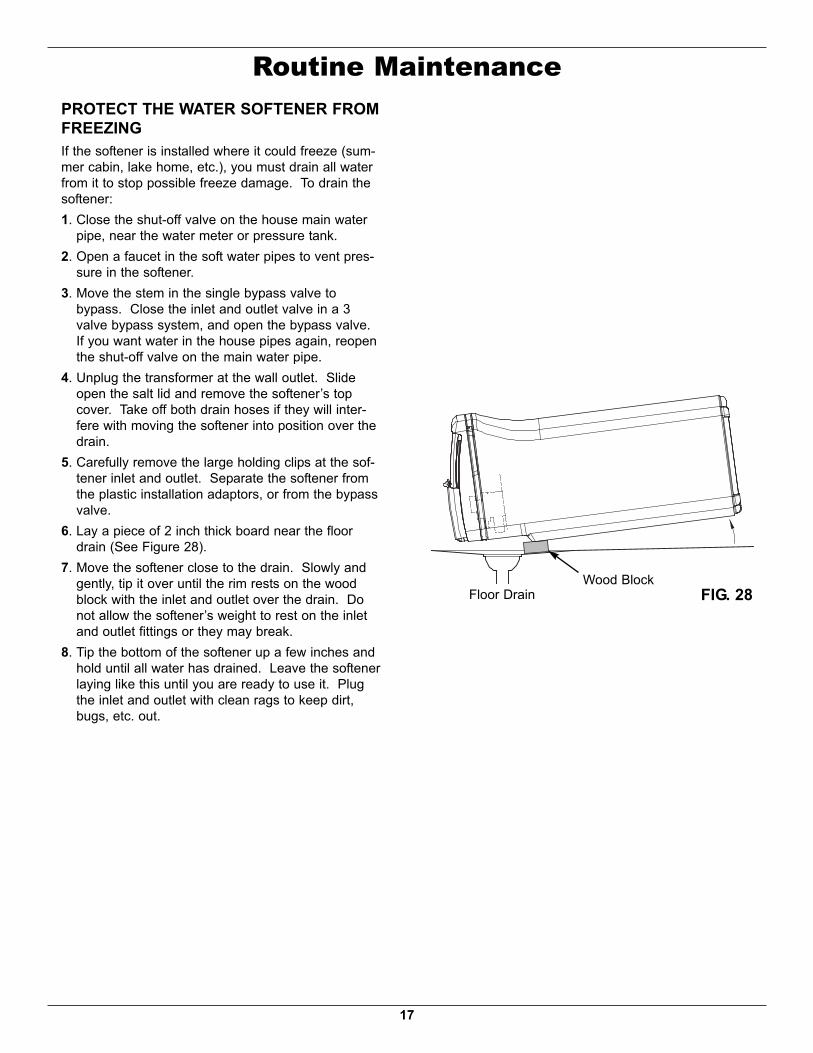
Routine MaintenancePROTECT THE WATER SOFTENER FROMFREEZINGIf the softener is installed where it could freeze (sum-mer cabin, lake home, etc.), you must drain all waterfrom it to stop possible freeze damage. To drain thesoftener:1. Close the shut-off valve on the house main water
pipe, near the water meter or pressure tank.2. Open a faucet in the soft water pipes to vent pres-
sure in the softener.3. Move the stem in the single bypass valve to
bypass. Close the inlet and outlet valve in a 3valve bypass system, and open the bypass valve.If you want water in the house pipes again, reopenthe shut-off valve on the main water pipe.
4. Unplug the transformer at the wall outlet. Slideopen the salt lid and remove the softener’s topcover. Take off both drain hoses if they will inter-fere with moving the softener into position over thedrain.
5. Carefully remove the large holding clips at the sof-tener inlet and outlet. Separate the softener fromthe plastic installation adaptors, or from the bypassvalve.
6. Lay a piece of 2 inch thick board near the floordrain (See Figure 28).
7. Move the softener close to the drain. Slowly andgently, tip it over until the rim rests on the woodblock with the inlet and outlet over the drain. Donot allow the softener’s weight to rest on the inletand outlet fittings or they may break.
8. Tip the bottom of the softener up a few inches andhold until all water has drained. Leave the softenerlaying like this until you are ready to use it. Plugthe inlet and outlet with clean rags to keep dirt,bugs, etc. out.
Floor Drain FIG. 28Wood Block

18
Troubleshooting GuidePROBLEM CAUSE CORRECTION
No soft water 1. No salt in the storage tank. Refill with salt and then use RECHARGE NOW feature.No soft water & dis-play is blank
1. Transformer unplugged at wall outlet, orpower cable disconnected from back ofelectronic board or transformer malfunction.
Check for loss of power and correct. Reset electroniccontrols and then use RECHARGE NOW feature.
2. Fuse blown, circuit breaker popped, or cir-cuit switched off (See “Power OutageMemory” on Page 14).
Replace fuse, reset circuit breaker, or switch circuit on,and then use RECHARGE NOW feature.
3. Electronic control board malfunction. Replace electronic control board (See Page 23).No soft water & saltlevel not dropping
1. Salt storage tank “bridged”. Refer to “Breaking a Salt Bridge” section to break.2. Bypass valve(s) in “bypass” position. Move bypass valve(s) to “service” position.
No soft water & saltstorage tank full ofwater,water running todrain while unit is inthe soft water cycle
1. Dirty, plugged or damaged nozzle & venturiassembly
Take apart, clean and inspect nozzle & venturi (See“Cleaning the Nozzle & Venturi” section.
2. Inner valve fault causing leak. Replace seals and rotor.3. Valve drain hose is plugged. Hose must not have any kinks, sharp bends or any water
flow blockage (See “Valve Drain Requirements” section.4. Valve drain line and Salt Storage Tank
overflow drain connected together by a tee.Disconnect tee and run separate drain lines.
5. Low or high system water pressure (lowpressure may disrupt brine draw duringrecharge, high pressure may cause innervalve parts failure).
If pressure is low, increase well pump output to a mini-mum 20 psi. If daytime pressure is over 100 psi, add apressure reducing valve in the supply pipe to the soften-er. Contact a licensed plumber.
6. Brine float dirty or broken. Clean or replace Brine Valve Float Assembly.*7. Leak between valve and resin tank. Replace o-rings between resin tank and valve.
Water hard some-times
1. Incorrect time set. Check and change time setting.2. Incorrect water hardness set. Refer to “Set Water Hardness” section to set correctly.3. Incorrect model code programmed. Refer to “Program the Water Softener” section to set cor-
rectly.4. Hot water being used when softener is
regenerating.Avoid using hot water while the softener is regenerating,as the water heater will fill with hard water.
5. Possible increase in water hardness. Test untreated water for hardness and iron, and programthe water softener accordingly (See “Set WaterHardness”) section to set.
6. Leaking faucet or toilet valve. Excessivewater usage.
A small leak can waste hundreds of gallons of water in afew days. Fix all leaks and always fully close faucets.
Iron in water 1. Clear water iron in water supply. Test untreated water for hardness and iron, and programthe water softener accordingly (See “Set WaterHardness”) section to set.
2. Iron in soft water. Clean resin bed with Resin Bed Cleaner. Follow instruc-tions on package.
3. Bacterial or organic bound iron. Cannot be treated by water softener.Resin in house holdplumbing
1. Crack in distributor or riser tube. Replace resin tank assembly.
Salt storage tankleaking
1. Crack in brine tank. Replace salt storage tank assembly.
Motor stalled orclicking
1. Motor malfunction or internal valve faultcausing high torque on motor.
a. Replace rotor/seal.b. Replace motor & switch.
Error code E1, E3 orE4 appears
1. Fault in wiring harness or connections toposition switch.
Replace wiring harness or connections to position switch.
2. Fault in switch. Replace switch.3. Fault in valve causing high torque. Replace rotor/seal.4. Motor inoperative. Replace motor.
Error code E5 1. Electronic control malfunction. Replace electronic control board.

19
Troubleshooting
The troubleshooting chart shows the error codes thatcould appear, and the possible malfunctions for eachcode.While an error code appears in the display, all buttonsare inoperable except the SELECT / MENU button.SELECT / MENU remains operational so the serviceperson can perform the Manual Advance Diagnostics,see below, to further isolate the problem.Procedure for removing error code from dis-play:
1. Unplug transformer from electrical outlet.2. Correct problem.3. Plug in transformer.4. Wait 8 minutes. The error code will return if
the problem was not corrected.
MANUAL ADVANCE DIAGNOSTICSUse the following procedures to advance the watersoftener through the regeneration cycles to checkoperation.Slide open the salt lid and remove the softener’s topcover to observe cam and switch operation duringvalve rotation.1. Press and hold SELECT / MENU for 3 seconds until
“000” shows in the display, then release.2. The 3 digits indicate water meter operation as fol-
lows:000 (steady) = Soft water not in use, and no flow
through the meter.Open a nearby soft water faucet.Model EP 7130: 000 to 199 (continual) =
Repeats for each gallon of waterpassing through the meter.
Model EP 7140: 000 to 140 (continual) =Repeats for each gallon of waterpassing through the meter.
NOTE: If you don't get a reading in the display withfaucet open, pull the sensor from the valveoutlet port. Pass a small magnet back andforth in front of the sensor. If you get a read-ing in the display with the magnet, unhook thein and out plumbing and check the turbine forbinding (See Figure 30).
3. The letter “P” and a dash (or dashes) indicatePOSITION switch operation (See Figure 31). If theletter appears, the switch is closed. If the dashshows, the switch is open.
4. Use the RECHARGE button to manually advancethe valve into each cycle and check correct switchoperation.
NOTE: Be sure water is in contact with the salt, andnot separated by a salt bridge (See "BreakingA Salt Bridge" section).
5. While in this diagnostic screen, the following infor-mation is available and may be beneficial for vari-ous reasons. This information is retained by thecomputer from the first time electrical power isapplied to the electronic controller.a. Press the r UP button to display the number of
days this electronic control has had electricalpower applied.
b. Press the s DOWN button to display the num-ber of regenerations initiated by this electroniccontrol since the code number was entered.
continued
AUTOMATIC ELECTRONIC DIAGNOSTICSThis water softener has a self-diagnostic function forthe electrical system (except input power and/or watermeter). The water softener monitors electronic com-ponents and circuits for correct operation. If a mal-function occurs, an error code appears in the display.
FIG. 29
FIG. 31
WaterMeter Switch
FIG. 30
Motor
PositionSwitch
ValveOutlet
Turbine
SensorHousing
TurbineSupport& Shaft
20
6. Press and hold the SELECT / MENU button untilthe model code (“E7130” for Model EP 7130 or“E7140” for Model EP 7140) shows in the display.This code identifies the softener model. If an incor-rect model code is displayed, the softener will oper-ate on incorrect configuration data.
7. To change the code number, press the r UP ors DOWN button until the correct code shows.
8. To return to the present time display, press theSELECT / MENU button.
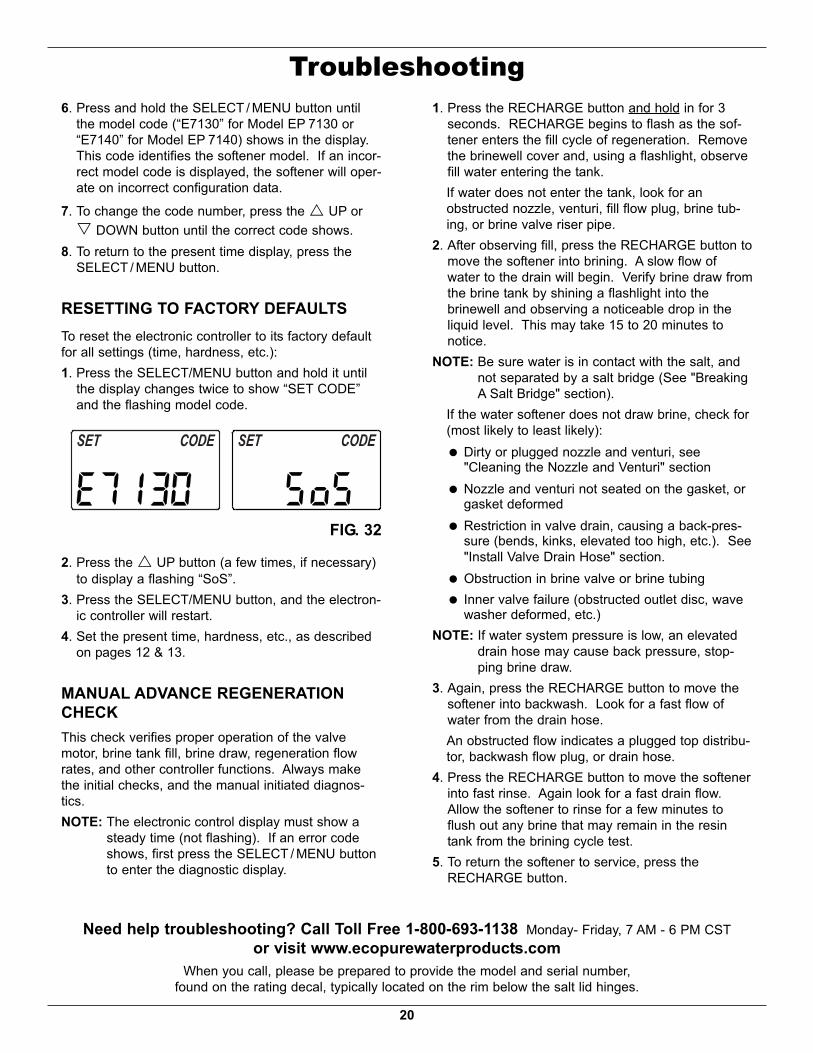
RESETTING TO FACTORY DEFAULTSTo reset the electronic controller to its factory defaultfor all settings (time, hardness, etc.):1. Press the SELECT/MENU button and hold it until
the display changes twice to show “SET CODE”and the flashing model code.
Troubleshooting
2. Press the r UP button (a few times, if necessary)to display a flashing “SoS”.
3. Press the SELECT/MENU button, and the electron-ic controller will restart.
4. Set the present time, hardness, etc., as describedon pages 12 & 13.
MANUAL ADVANCE REGENERATIONCHECKThis check verifies proper operation of the valvemotor, brine tank fill, brine draw, regeneration flowrates, and other controller functions. Always makethe initial checks, and the manual initiated diagnos-tics.NOTE: The electronic control display must show a
steady time (not flashing). If an error codeshows, first press the SELECT / MENU buttonto enter the diagnostic display.
1. Press the RECHARGE button and hold in for 3seconds. RECHARGE begins to flash as the sof-tener enters the fill cycle of regeneration. Removethe brinewell cover and, using a flashlight, observefill water entering the tank.If water does not enter the tank, look for anobstructed nozzle, venturi, fill flow plug, brine tub-ing, or brine valve riser pipe.
2. After observing fill, press the RECHARGE button tomove the softener into brining. A slow flow ofwater to the drain will begin. Verify brine draw fromthe brine tank by shining a flashlight into thebrinewell and observing a noticeable drop in theliquid level. This may take 15 to 20 minutes tonotice.
NOTE: Be sure water is in contact with the salt, andnot separated by a salt bridge (See "BreakingA Salt Bridge" section).
If the water softener does not draw brine, check for(most likely to least likely):= Dirty or plugged nozzle and venturi, see
"Cleaning the Nozzle and Venturi" section= Nozzle and venturi not seated on the gasket, or
gasket deformed= Restriction in valve drain, causing a back-pres-
sure (bends, kinks, elevated too high, etc.). See"Install Valve Drain Hose" section.
= Obstruction in brine valve or brine tubing= Inner valve failure (obstructed outlet disc, wave
washer deformed, etc.)NOTE: If water system pressure is low, an elevated
drain hose may cause back pressure, stop-ping brine draw.
3. Again, press the RECHARGE button to move thesoftener into backwash. Look for a fast flow ofwater from the drain hose.An obstructed flow indicates a plugged top distribu-tor, backwash flow plug, or drain hose.
4. Press the RECHARGE button to move the softenerinto fast rinse. Again look for a fast drain flow.Allow the softener to rinse for a few minutes toflush out any brine that may remain in the resintank from the brining cycle test.
5. To return the softener to service, press theRECHARGE button.
Need help troubleshooting? Call Toll Free 1-800-693-1138 Monday- Friday, 7 AM - 6 PM CSTor visit www.ecopurewaterproducts.com
When you call, please be prepared to provide the model and serial number,found on the rating decal, typically located on the rim below the salt lid hinges.
FIG. 32

21
Notes

22
Softener Exploded View(Models EP 7130 & EP 7140)
8
7
6
5
1
2
18
345
6 7
8
9
11
Valve AssemblySee Pages 24 - 27
for parts
29
10
12
13
14
3117
19
15
20
22
21
23
24
25
26
27
28
16
30
70 or 121
72 or 123

23
Softener Parts List(Models EP 7130 & EP 7140, as listed below)
KeyNo. Part No. Description
– 7331177 Tank Neck Clamp Kit(includes 2 ea. of Key Nos. 1 & 2)
1 á Clamp Section (2 req.)2 á Retainer Clip (2 req.)– 7112963 Distributor O-Ring Kit
(includes Key Nos. 3-5)3 á O-Ring, 2-7/8” x 3-1/4”4 á O-Ring, 13/16” x 1-1/16”5 á O-Ring, 2-3/4” x 3”6 7077870 Top Distributor7 7105047 Repl. Bottom Distributor
87328904 Repl. Resin Tank, 9” x 35”,
Model EP 71307113066 Repl. Resin Tank, 10” x 35”,
Model EP 71409 0502272 Resin, 1 cu. ft.
10 7310202 Repl. Brine Valve Assembly11 7327568 Float, Stem & Guide Assembly12 7269930 Electronics Enclosure, Rear13 7281089 Faceplate (order decal below)¢ 7303158 Faceplate Decal14 7303221 Repl. Electronic Control Board (PWA)15 7269914 Salt Lid16 7303077 EcoPure Badge17 7294707 Top Cover
KeyNo. Part No. Description18 7275907 Transformer19 7295046 Rim (order decal below)¢ 7302932 Instruction Decal20 7155115 Brinewell Cover21 7137824 Brinewell– 7331672 Brinewell Mounting Hardware Kit
(includes Key Nos. 22-24)22 á Wing Nut, 1/4-2023 á Spacer, Brinewell24 á Screw, 1/4-20 x 1”
25 7311169 Repl. Brine Tank, Model EP 71307295567 Repl. Brine Tank, Model EP 7140
– 7331258 Overflow Hose Adaptor Kit(includes Key Nos. 26-28)
26 á Adaptor Elbow27 á Grommet28 á Hose Clamp29 7139999 Drain Hose, 20 ft.30 7248706 Ground Clamp Kit
317278434
Bypass Valve Assembly, 3/4”, ModelEP 7130, including 2 O-Rings(See Key No. 72)
7214383Bypass Valve Assembly, 1”, ModelEP 7140, including 2 ea.of Clips &O-Rings (See Key Nos. 121 & 123)
¢ 7339913 Owner’s Manual
To order repair parts call toll free 1-800-693-1138, Monday - Friday, 7 AM - 6 PM CST.Manufactured and warranted by
Ecodyne Water Systems1890 Woodlane DriveWoodbury, MN 55125
¢ Not illustrated.
Questions? Call Toll Free 1-800-693-1138 Monday- Friday, 7 AM - 6 PM CSTor visit www.ecopurewaterproducts.com
When you call, please be prepared to provide the model and serial number,found on the rating decal, typically located on the rim below the salt lid hinges.

24
Valve Exploded View
51
50
52
5355
56
59 58
57
6061
6667
62
63
6468
69
70
7172
7374
75
65
76
777978
80
81
82
Wear Strip
SealCross-section
View
83
84
85
86
87
88
89
9054
25
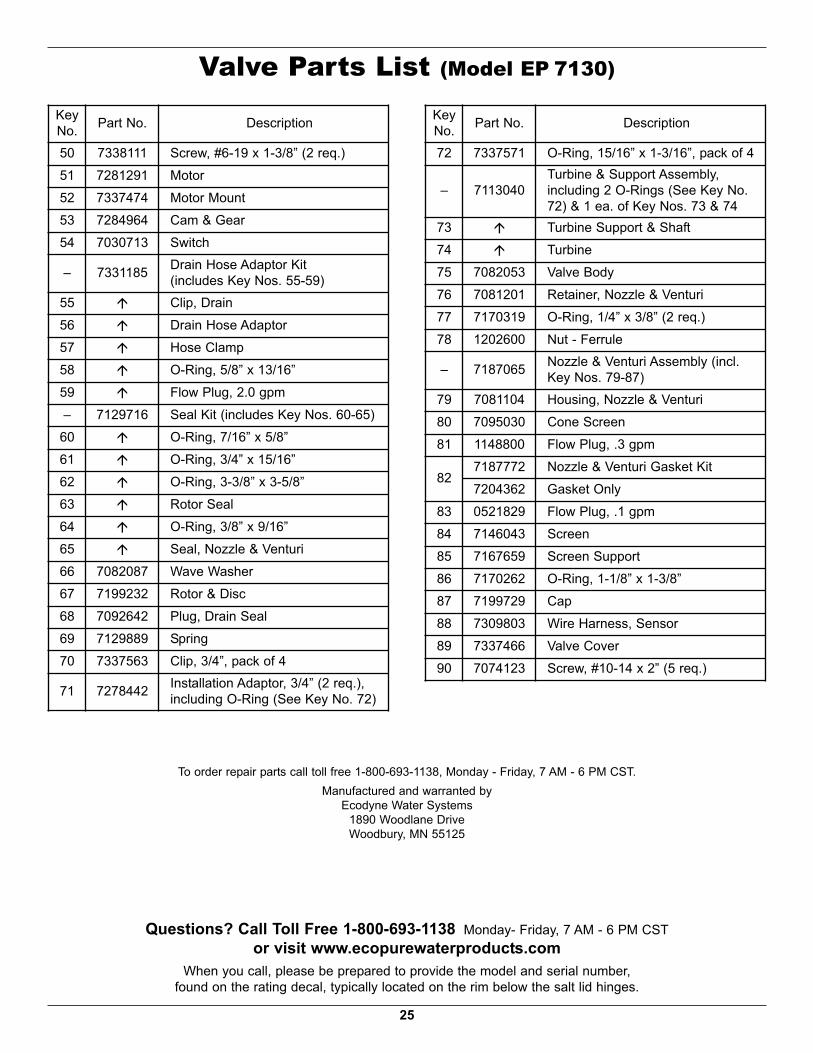
KeyNo. Part No. Description50 7338111 Screw, #6-19 x 1-3/8” (2 req.)51 7281291 Motor52 7337474 Motor Mount53 7284964 Cam & Gear54 7030713 Switch– 7331185 Drain Hose Adaptor Kit
(includes Key Nos. 55-59)55 á Clip, Drain56 á Drain Hose Adaptor57 á Hose Clamp58 á O-Ring, 5/8” x 13/16”59 á Flow Plug, 2.0 gpm– 7129716 Seal Kit (includes Key Nos. 60-65)
60 á O-Ring, 7/16” x 5/8”61 á O-Ring, 3/4” x 15/16”62 á O-Ring, 3-3/8” x 3-5/8”63 á Rotor Seal64 á O-Ring, 3/8” x 9/16”65 á Seal, Nozzle & Venturi66 7082087 Wave Washer67 7199232 Rotor & Disc68 7092642 Plug, Drain Seal69 7129889 Spring70 7337563 Clip, 3/4”, pack of 471 7278442 Installation Adaptor, 3/4” (2 req.),
including O-Ring (See Key No. 72)
KeyNo. Part No. Description72 7337571 O-Ring, 15/16” x 1-3/16”, pack of 4
– 7113040Turbine & Support Assembly,including 2 O-Rings (See Key No.72) & 1 ea. of Key Nos. 73 & 74
73 á Turbine Support & Shaft74 á Turbine75 7082053 Valve Body76 7081201 Retainer, Nozzle & Venturi77 7170319 O-Ring, 1/4” x 3/8” (2 req.)78 1202600 Nut - Ferrule– 7187065 Nozzle & Venturi Assembly (incl.
Key Nos. 79-87)79 7081104 Housing, Nozzle & Venturi80 7095030 Cone Screen81 1148800 Flow Plug, .3 gpm
82 7187772 Nozzle & Venturi Gasket Kit7204362 Gasket Only
83 0521829 Flow Plug, .1 gpm84 7146043 Screen85 7167659 Screen Support86 7170262 O-Ring, 1-1/8” x 1-3/8”87 7199729 Cap88 7309803 Wire Harness, Sensor89 7337466 Valve Cover90 7074123 Screw, #10-14 x 2” (5 req.)
To order repair parts call toll free 1-800-693-1138, Monday - Friday, 7 AM - 6 PM CST.Manufactured and warranted by
Ecodyne Water Systems1890 Woodlane DriveWoodbury, MN 55125
Questions? Call Toll Free 1-800-693-1138 Monday- Friday, 7 AM - 6 PM CSTor visit www.ecopurewaterproducts.com
When you call, please be prepared to provide the model and serial number,found on the rating decal, typically located on the rim below the salt lid hinges.
Valve Parts List (Model EP 7130)

26
Valve Exploded View (Model EP 7140)
wear-strip
sealcross-section
view
100101
102
103
104
105
106
107108109110
111112117
118
113
140
114
115119
120
121
122
123
124125
127
126
116
128
129131130
132133
134
135
136
137
138
139
141
142
143
144
27
Valve Parts List (Model EP 7140)
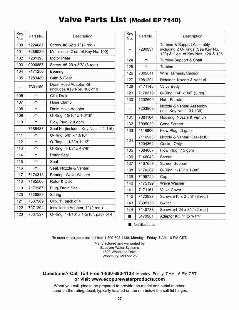
To order repair parts call toll free 1-800-693-1138, Monday - Friday, 7 AM - 6 PM CST.Manufactured and warranted by
Ecodyne Water Systems1890 Woodlane DriveWoodbury, MN 55125
KeyNo. Part No. Description100 7224087 Screw, #8-32 x 1” (2 req.)101 7286039 Motor (incl. 2 ea. of Key No. 100)102 7231393 Motor Plate103 0900857 Screw, #6-20 x 3/8” (3 req.)104 7171250 Bearing105 7283489 Cam & Gear
– 7331169 Drain Hose Adaptor Kit(includes Key Nos. 106-110)
106 á Clip, Drain107 á Hose Clamp108 á Drain Hose Adaptor109 á O-Ring, 15/16” x 1-3/16”110 á Flow Plug, 2.0 gpm– 7185487 Seal Kit (includes Key Nos. 111-116)
111 á O-Ring, 5/8” x 13/16”112 á O-Ring, 1-1/8” x 1-1/2”113 á O-Ring, 4-1/2” x 4-7/8”114 á Rotor Seal115 á Seal116 á Seal, Nozzle & Venturi117 7174313 Bearing, Wave Washer118 7185500 Rotor & Disc119 7171187 Plug, Drain Seal120 7129889 Spring121 7337589 Clip, 1”, pack of 4122 7271204 Installation Adaptor, 1” (2 req.)123 7337597 O-Ring, 1-1/16” x 1-5/16”, pack of 4
KeyNo. Part No. Description
– 7290931Turbine & Support Assembly,including 2 O-Rings (See Key No.123) & 1 ea. of Key Nos. 124 & 125
124 á Turbine Support & Shaft125 á Turbine126 7309811 Wire Harness, Sensor127 7081201 Retainer, Nozzle & Venturi128 7171145 Valve Body129 7170319 O-Ring, 1/4” x 3/8” (2 req.)130 1202600 Nut - Ferrule
– 7253808 Nozzle & Venturi Assembly(incl. Key Nos. 131-139)
131 7081104 Housing, Nozzle & Venturi132 7095030 Cone Screen133 1148800 Flow Plug, .3 gpm
134 7114533 Nozzle & Venturi Gasket Kit7204362 Gasket Only
135 7084607 Flow Plug, .15 gpm136 7146043 Screen137 7167659 Screen Support138 7170262 O-Ring, 1-1/8” x 1-3/8”139 7199729 Cap140 7175199 Wave Washer141 7171161 Valve Cover142 7172997 Screw, #10 x 2-5/8” (8 req.)143 7305150 Switch144 7140738 Screw, #4-24 x 3/4” (2 req.)¢ 3479901 Adaptor Kit, 1” to 1-1/4”¢ Not illustrated.
Questions? Call Toll Free 1-800-693-1138 Monday- Friday, 7 AM - 6 PM CSTor visit www.ecopurewaterproducts.com
When you call, please be prepared to provide the model and serial number,found on the rating decal, typically located on the rim below the salt lid hinges.