Embed Size (px)
Citation preview
© S-COM LLC, 2006 Page 1
New Directions in Repeater Controllers: Presenting the S-COM 7000 Series
1 INTRODUCTION Why does the world need another repeater controller? It’s because our hobby is changing. No one will argue that amateur radio repeaters are valuable assets, especially during emergencies. Wide-range linked repeater systems help us serve the public interest even more. But good sites are getting scarcer and more costly, so some groups are choosing to add repeaters to the sites they already have. They need to find the best and least expensive way to control multiple on-site repeaters. At the same time, other groups are able to expand their systems into more sites. They need to find the best and least expensive way to manage repeaters interconnected with half-duplex and full-duplex links. With over 25 years of controller building experience, we at S-COM are proud to present a new line of flexible and affordable controllers that solve your problems – regardless of the kind of system you have. In Section 2 we’ll discuss three key facets of the 7000 series: Flexible Ports, Digital Audio Playback, and Fast Programming. In Sections 3 through 15 we’ll describe the first member of the series, the 7330.
© S-COM LLC, 2006 Page 2
2 NEW DIRECTIONS 2.1 Flexible Ports Most multiport repeater controllers have one main port and a couple of auxiliary ports. The main port gets the DTMF decoder, the tone generator, the speech synthesizer, and the fancy software. The other ports simply mix with the main port and share its resources. Auxiliary ports are fine for controlling simple link radios, but they’re insufficient for controlling repeaters. Some products are sold as multiple repeater controllers. Although offering such improvements as individual DTMF decoders, most can’t do things like send different CW or stored audio messages to each transmitter at the same time. Using a separate controller for each repeater seems like a solution until you try to interconnect the controllers. Creating a proper audio distribution scheme and getting the controllers to communicate among themselves are just two of the jobs requiring serious effort under good conditions. The task becomes that much harder under emergency conditions. S-COM’s approach calls for each port to be identical, independent, and in charge of its own resources so that no resource sharing is needed. Every port can handle either a full duplex or a half duplex device. Thus, every port can be a repeater port, a link port, a control port, a remote base port, or any other kind of port. And depending on the need at the time, the controller can “group” and “ungroup” any combination of ports on command. Specifically, the 7330 – with its three receiver interfaces, transmitter interfaces, DTMF decoders, CTCSS encoders, digital audio players, identifiers, courtesy messages, tail sequences, and so on – can be a triple repeater controller. It can just as easily be a crossband repeater controller or a linking system controller. How does it work? Internally, the 7330 handles the three receivers and three transmitters as six individual devices. No receiver is hardwired to any transmitter, thus the 7330 doesn’t require you to use certain ports for repeaters and other ports for links or control receivers. In fact, there’s no advantage or disadvantage in using a given port for a given task. Instead, you remotely configure any receiver or any transmitter for any application. Furthermore, if you choose to have multiple receivers feed a transmitter, you can either prioritize or mix each receiver to the transmitter. It takes nine circuit paths to totally interconnect three receivers and three transmitters. The 7330 gives you full programmability over all nine paths. There are three additional paths that connect the three receivers to their DTMF decoders. You can choose various settings for these three paths as well, such as whether CTCSS or carrier is needed to enter DTMF commands. Some software functions are based on the individual path. For example, each path has a method of access (carrier, CTCSS, etc.) and each path has its own timeout timer. Identifiers, on the other hand, are based on the individual transmitter; long-tone DTMF macros are based on the individual DTMF decoder; and COR pulse-triggered macros are based on the individual COR input.
© S-COM LLC, 2006 Page 3
Here are some examples of what you can do with a 7330. Assume that the 7330 is in its default state, which means the RX1-TX1 path is in carrier access mode, the timeout timer is 3.0 minutes, there is a single courtesy beep, and so on. Let’s say you connect a repeater to the RX1-TX1 port and configure the RX1-TX1 path for CTCSS access, a five-minute timeout timer, and a dual courtesy beep. (There are many other functions available as well!) Later, you add a control receiver to the RX3 input. You leave the RX3-TX1 path turned off because you normally don’t want the control receiver’s audio repeated. But you create a macro command that sets the RX3-TX1 path for CTCSS access, a ten-minute timeout timer, and a special courtesy beep. You can now use the macro as a priority override command for important announcements. When the RX3-TX1 path is no longer needed, you can enter another macro that you created to turn it off. At some point you connect a simplex link transceiver to the RX2-TX2 port. You turn off the RX2-TX2 path because the link is not full duplex. You program a path from RX2 to TX1 (the repeater transmitter) that has CTCSS access, a six-minute timeout, and two beeps. (By making the courtesy beep different for each path, users will know whether the signal came from the repeater side or the link side.) You program the path from the repeater receiver (RX1) to the link transmitter (TX2) for CTCSS access, a ten-minute timeout, and no tail so the link transmitter drops quickly. Later, you remove the control receiver from RX3 because you want to add another repeater, and you connect the repeater to the RX3-TX3 port. Since you want this repeater to operate independently, you turn on only the path from RX3 to TX3. But you create macro commands that tie and untie the new repeater to the original one just in case you’ll need that ability some time (the paths are RX3-TX1 and RX1-TX3). If desired, you can create macros to tie and untie the RX3-TX3 repeater to the simplex link. As you can see, any path from any receiver to any transmitter can be set up, modified, and knocked down at any time, allowing the utmost flexibility. This idea came from a customer: Add a low-powered transmitter to your repeater site that can be monitored by control operators. The path from the repeater receiver to this small transmitter is set for simple carrier access, even though the path from the repeater receiver to the repeater transmitter is heavily protected with CTCSS, a key-up (antikerchunk) delay, and so on. That way, the control ops can hear all the activity at the repeater receiver input, a big help when troubleshooting interference. 2.2 Digital Audio Playback Why put digital audio playback capability in a controller? Few repeater users understand CW any more, so some sort of stored speech capability is needed. Some messages are short and fixed, like command responses and time and date messages. Some are longer, such as announcements to draw
© S-COM LLC, 2006 Page 4
attention to a great presentation at the next club meeting or to notify users of a developing emergency situation. Synthesized speech is a nearly obsolete technology with very few IC manufacturers and language labs still in the business. Even when it was popular, synthesized speech messages sounded unnatural because sentences were made up of words with individual inflections. Cities, landmarks, and proper names didn’t exist in standard vocabularies and had to be created at extra cost. Voice recorder ICs lose a portion of their short playback time to the fixed messages mentioned above. Often mislabeled as “DVRs” (Digital Voice Recorders), they’re analog recorders with narrow responses and low signal-to-noise ratios. Recording must be done in real time in the analog domain, requiring digital sound files to first be converted to analog with the accompanying noise and losses. On the other hand, the 7330 has individual digital audio playback capability on each of the three ports. The user can remotely load digital audio files via the 7330’s serial programming port. There’s plenty of flash storage for both a standard library and custom messages. You can use your PC and third-party software to record a message, upload it to the repeater controller, and specify how and when the announcement should be made. 2.3 Fast Programming As controllers become more sophisticated, uploading their programming takes longer. The 7330 has a large amount of on-board flash memory and accepts operating system upgrades and digital audio files as well as user programming. But since it’s difficult to do long, error-free DTMF sessions, the 7330 offers fast RS-232 upload ability as well as traditional DTMF programming. With our software, you can update your controller as well as get a complete snapshot of the current programming setup. Maintaining your repeater controller programming is simple and straightforward with checkboxes and drop down choices. Incidentally, if you’re used to programming S-COM controllers, you’ll find the 7000 series’ command set very familiar. We’ve expanded it include the additional ports and to give you control over parameters that were previously fixed.
© S-COM LLC, 2006 Page 5
3 NEW HARDWARE DESIGN 3.1 SoC If the features just mentioned – flexible ports, digital audio playback, and fast programming – are so important, why haven’t other controllers offered them before? Cost and complexity: It takes more board space, components, processors and difficult software to build a true multi-repeater controller in the traditional way. What are we doing that’s different? The heart of the 7000 series is a proprietary, highly integrated, System-on-a-Chip (SoC). There are many advantages in using such a device in a modern design:
The board’s size and cost is reduced because the total number of ICs is reduced.
There’s no need for certain specialty ICs (such as speech synthesizers) when
the job can be done inside the SoC. And specialty ICs can be expensive and hard to find when their underlying technologies become obsolete.
With most of the complex functions inside the SoC, the remainder of the
design can be implemented with low-cost, readily available components. The design is highly flexible because the SoC is a programmable device. It
can be upgraded, modified, and tweaked for increased performance or to change its capabilities.
Because peripherals are implemented in hardware, the speed and capability
of the design is increased without requiring an expensive processor and complex software algorithms.
RFI is reduced due to the high level of integration of digital circuitry into one
IC. Only a few short buses are needed to communicate with external ICs. What’s inside the SoC? Quite a lot: A processor core; address decoding logic; an SRAM interface with a 4k-page-select Memory Management Unit; a serial flash memory interface; a 4k boot ROM; an interrupt priority encoder; six Numerically Controlled Oscillators; digital audio playback DMA logic; two UARTs; SPI interfaces for digital potentiometer control, RTC control and front panel interface; parallel ports; watchdog timer trigger logic; a 16-bit timer; and three DTMF decoder interface ports. 3.2 Memory The 7330 has 16M bytes of flash memory for operating system storage and digital audio file storage, and 512k bytes of battery-backed CMOS RAM with write protection. Firmware upgrades can be done via the RS-232 programming port.
© S-COM LLC, 2006 Page 6
4 RECEIVER INTERFACE The main components of each receiver audio input are an input level pot, an op amp stage with a response jumper, and a second op amp stage with a gain jumper. The input impedance varies with pot setting and is 25K ohms or greater. The response jumper configures the first op amp as either a unity gain buffer (FLAT position) or a de-emphasis stage with gain (DE-EMP position). The DE-EMP position is used when using discriminator (rising response) audio. The de-emphasis corner is 200 Hz. The gain jumper sets the second op amp’s gain to 2.0 (NORM position) or 6.3 (HIGH position). The overall gain of the circuit is halved when the pot is at 50%, so the gain is 1.0 in the NORM position and 3.1 in the HIGH position when the pot is in the middle. By having separate stages for response and gain, we can more easily modify the receiver interface for special applications. When the level pot is properly adjusted, the audio level at TP9 (RX1), TP10 (RX2), and TP11 (RX3) should be 1.0 V peak-to-peak or 354 mVrms. Digital audio delay is built into each receiver port, and the choice of delayed or nondelayed audio is made via jumper. The delay is set by potentiometer and ranges from 30 to 250 mS. Three MT8870s are used for DTMF decoding, one for each receiver. The software can extend the digit detection time beyond the value set by the R and C components. That way, the user can control falsing by commanding the decoder to require more digit detection time.
© S-COM LLC, 2006 Page 7
5 TRANSMITTER INTERFACE The main components in each transmitter audio output circuit are a mixing op amp, a level pot, and a driver op amp with an attenuation jumper. The output impedance is 600 ohms. The attenuation jumper allows the controller to handle a wide range of output levels. It sets the driver op amp’s gain to 2.0 (NORM position) or 0.5 (LOW position). The overall gain of the circuit is halved when the pot is at 50%, so the gain is 1.0 in the NORM position and 0.25 in the HIGH position when the pot is in the middle. The LOW position is used when feeding sensitive transmitter audio inputs. Large-value, nonpolarized ceramic capacitors are used for transmitter audio and CTCSS encoder coupling. Large values allow wide frequency response even when driving low transmitter input impedances, and nonpolarized capacitors aren’t susceptible to reverse bias problems when connected to audio lines carrying DC. Each PTT circuit is controlled by an open drain power MOSFET rated at 45 V and 150 mA. Transmitter PTT drivers are contained in socketed 20-pin DIP ICs along with logic output drivers. The drivers are open drain power MOSFETs rated at 45 V, 150 mA.
© S-COM LLC, 2006 Page 8
6 AUDIO DESIGN 6.1 Flatness No audio manipulation takes place beyond de-emphasis and level control. In fact, the audio response is quite flat due to such techniques as the use of large value (1 uF and 10 uF) nonpolarized coupling caps throughout the audio chain. With a 600-ohm load at the transmitter audio output, and the audio delay not selected, the response between the –3 dB points is 18 Hz to 16 kHz. The low-end figure is 11 Hz with a 10K ohm load. With a 600-ohm load and the audio delay selected, the response between the –3 dB points is 25 Hz to 6.2 kHz. The low-end figure is 18 Hz with a 10K ohm load. 6.2 DTMF Decoders Each receiver audio input feeds its own MT88L70 DTMF decoder. 6.3 Pots We used mechanical pots for adjusting the receiver and transmitter audio levels, the CTCSS encode levels, and the durations of the audio delays, to reduce cost. These are ‘calibration’ adjustments, done at installation time and seldom needing adjustment afterward. There are twelve pots on the 7330’s Main Board. However, we found good advantages in using electronic pots for controller-generated signaling, including CW, beeps, paging tones, and digital audio playback.
Remote programmability is a plus. Many a repeater tech has made a trip to a site to change a CW ID that was too loud or a courtesy beep that was too soft. It’s difficult to set things that are dictated by taste perfectly during installation.
Programmable levels let us choose different levels for test tones, CW
messages, beeps, and tone pages, even when all are generated by the same hardware. The alternative requires pots and audio selector switches for each type of signaling on each port.
The 7330 has three 256-step digital pots, one for each port. The levels are adjusted via codes the user programs into messages. That way, the user can set a level for a custom tone page or even change the level within a message as an attention getter. 6.4 Audio Gating Another reason we gave each port its own set of resources is that the audio gating requirements become quite simple. Here's why. The S-COM 6K, 7K, and some other controllers use a crosspoint switch IC to connect the various audio sources and loads under microprocessor control. The 7K's
© S-COM LLC, 2006 Page 9
crosspoint switch, for example, has twelve inputs and eight outputs. It can connect any of its three receivers to the two transmitters and to the DTMF decoder; it can connect the CW generator to either or both transmitters; and so on. But a portion of the crosspoint is no longer needed if each receiver has its own DTMF decoder. And another portion goes away if each transmitter has its own tone generator and digital audio playback. What remains is receiver-to-transmitter gating, which is easily done with simpler and cheaper parts than a crosspoint switch. In fact, the 7330 controller uses just three triple-SPDT audio switches to connect each receiver to one of the mixer inputs of each transmitter.
© S-COM LLC, 2006 Page 10
7 CTCSS ENCODERS The 7330 features three CTCSS tone encoders, one for each port. Pin 8 of each DB9F port connector is used for the encode function. A jumper connects pin 8 to either the CTCSS tone output or an extra logic output that can be used to control an external CTCSS encoder. The SoC contains three Numerically Controlled Oscillators (NCOs). Each generates a digital representation of a CTCSS tone. Each NCO then drives a Digital-to-Analog Converter (DAC) to generate a near-sine analog waveform. The DAC output feeds a fifth-order lowpass filter because we don’t want products from the sampling process showing up in the voice passband. The result is a smooth waveform with low distortion (THD is –35 dB at 67.0 Hz to –70 dB at 203.5 Hz). And because they’re Butterworth filters and have a flat passband, changing the frequency within that range doesn’t change the level appreciably. An op amp stage buffers the level pot and sets the output impedance at 2K ohms. Without the buffer, the output level would change with loading. The output level is adjustable from 0 to 2 volts peak-to-peak. Tone accuracy is better than 0.02%. The CTCSS generator has 180-degree phase reversal capability. Like the 7K, the 7330 has a command to set the CTCSS tone frequency and control when its output is on. The command can be used with Event-Triggered Macros, thus providing lots of flexibility in control.
© S-COM LLC, 2006 Page 11
8 SINGLE/DUAL TONE ENCODERS The 7330 features three voice-band dual tone encoders, one for each port. Single tones as well as dual tones can be generated for CW, beeps, and paging purposes (including DTMF and SELCAL). The levels are remotely programmable. The SoC contains three unique Numerically Controlled Oscillators. Each generates a digital representation of a single tone or the sum of two tones. Each NCO then drives a Digital-to-Analog Converter (DAC) to generate an analog waveform. The DAC output feeds a fifth-order lowpass filter because we don’t want products from the sampling process showing up in adjacent channels. The result is a smooth waveform with low distortion (THD is -35 dB at 100 Hz to –66 dB at 3 kHz). And because they’re Butterworth filters and have a flat passband, changing the frequency within that range doesn’t change the level appreciably. (Unfortunately, adjacent-channel interference from tone generators and synthesizers in some competitive controllers is common. Experienced repeater system builders know that a repeater transmitter’s single-pole splatter filter cannot remove all the noise and harmonics created by poorly-filtered digitally generated speech and tones.) Tone accuracy is better than 0.12% for in-band tones up to 1700 Hz.
© S-COM LLC, 2006 Page 12
9 DIGITAL AUDIO PLAYBACK The 7330 can play digital audio on each of its three ports independently. Digital audio files are stored in flash memory in 8-bit, 8 ksps, u-Law-encoded format. The total available digital audio storage is 7M bytes (about 15 minutes). "Don’t forget the ARES net, Wednesday at nine PM, on this repeater” takes about five seconds and consumes about 40k bytes of storage. “The monthly meeting of the Northern Colorado Amateur Radio Club will be held Saturday at the Golden Corral restaurant on Harmony Road. Breakfast starts at eight” takes about eight seconds and requires about 64k bytes of storage. The SoC fetches the u-Law-compressed digital audio data from the flash and converts it to linear data. The data is fed to the appropriate voice-band tone DAC to generate an analog waveform. The 5th-order lowpass filter removes products of the sampling process to yield a low-distortion waveform.
© S-COM LLC, 2006 Page 13
10 REAL-TIME CLOCK/CALENDAR A real-time clock IC provides time and date information and has a socketed lithium battery for backup. A 32.768 kHz temperature compensated crystal oscillator (TCXO) provides better timekeeping accuracy than ordinary crystal oscillators. The TCXO output is accurate to ±1 min/year from 0°C to 40°C. A 100-setpoint scheduler is provided.
© S-COM LLC, 2006 Page 14
11 LOGIC INPUTS AND OUTPUTS There are four user inputs for monitoring external logical (on/off) devices. Each logic input has an associated pullup resistor enabled with a jumper. The status of each logic input is reported via an LED on the front panel. There are eight open-drain user outputs for manipulating external logical (on/off) devices. The driver for these outputs is a DIP-type IC, socketed for easy replacement. Each logic output can handle 45 VDC in the off state and 150 mA in the on state. The status of each logic output is reported via an LED on the front panel.
© S-COM LLC, 2006 Page 15
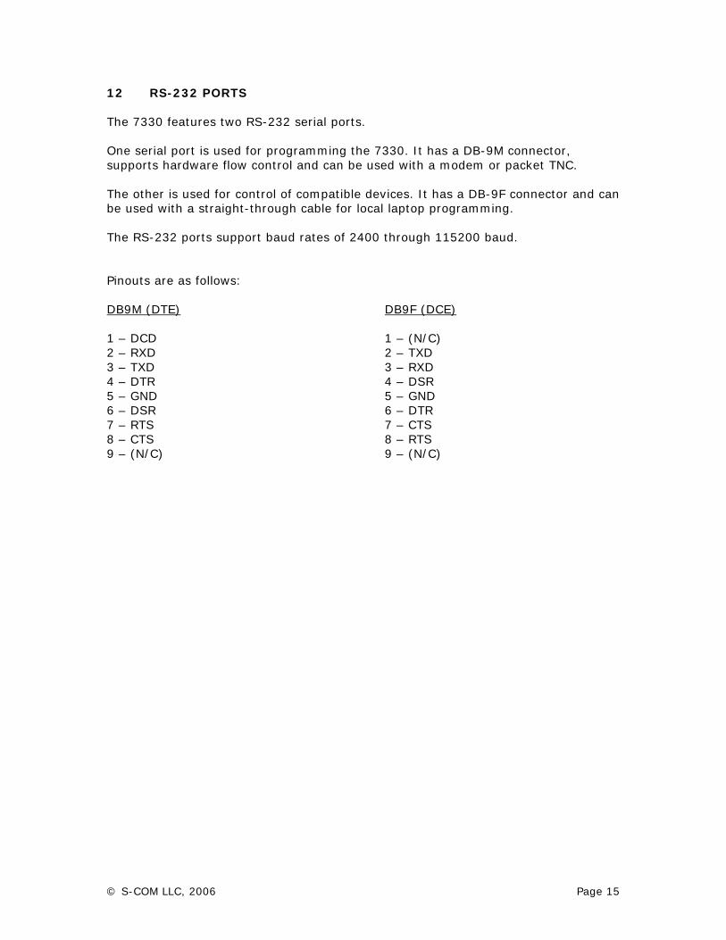
12 RS-232 PORTS The 7330 features two RS-232 serial ports. One serial port is used for programming the 7330. It has a DB-9M connector, supports hardware flow control and can be used with a modem or packet TNC. The other is used for control of compatible devices. It has a DB-9F connector and can be used with a straight-through cable for local laptop programming. The RS-232 ports support baud rates of 2400 through 115200 baud. Pinouts are as follows: DB9M (DTE) 1 – DCD 2 – RXD 3 – TXD 4 – DTR 5 – GND 6 – DSR 7 – RTS 8 – CTS 9 – (N/C)
DB9F (DCE) 1 – (N/C) 2 – TXD 3 – RXD 4 – DSR 5 – GND 6 – DTR 7 – CTS 8 – RTS 9 – (N/C)
© S-COM LLC, 2006 Page 16
13 A/D INPUTS The controller features three user analog inputs. Each input can be jumpered for either a 0 to +5 V range or a 0 to +25 V range. A clamping circuit prevents damage to the ADC (analog-to-digital converter) in case an excessive voltage is applied to the controller’s A/D inputs.
© S-COM LLC, 2006 Page 17
14 POWER SUPPLY External power is fed to the controller via a locking Phoenix screw terminal plug. A series diode furnishes input polarity protection. The first stage in the controller’s power supply is a switching +5 V regulator. It drives linear regulators that provide +3.3 V, +2.5 V, and +1.2 V. A switching regulator is used in the first stage because it has two big advantages over a linear regulator. One is efficiency. Using a switching regulator improves the product’s reliability because the power supply is no longer a major heat source. No heat sinks or ventilation holes are needed. The other is a very wide input voltage range. The controller can operate from +9 V to +36 V, so it’ll work equally well with a +10 V, +12 V, +13.8 V, or +24 V DC supply. Why is a wide input range important? Let’s look at two extremes. Consider what happens if the controller has a narrow supply range and the site has a backup battery: When the main power fails, the battery takes over. When the battery voltage drops below the controller’s minimum supply threshold, the controller stops working. It won’t accept commands or key the transmitter. But with so little current drain, the battery voltage eventually rises and the controller restarts. The transmitter keys, draining the battery, and the cycle repeats. Or maybe when the controller stops working it freezes the push-to-talk line in the active state and keeps the transmitter keyed. Either way, the site can’t be controlled and the batteries can be damaged. The solution is to use a controller that works at the lowest possible battery sag voltage. At the other extreme, the 7330 will work from a +24 V supply and will withstand similar voltages that might show up on a +13.8 V system power bus if the pass transistors in the site power supply fail. What is the 7330’s power consumption? Preliminary testing shows it to be only about 1.5 watts. Since the switcher’s efficiency doesn’t change much with input voltage, we can use I = P/E to estimate the controller’s current requirements at various voltages. For example, the current drain at 10 V is about 150 mA and about 109 mA at 13.8 V. Despite these low figures, don’t use a current-limited, very low current power supply; there are two 470-uF capacitors on the power input that need to charge on power up.
© S-COM LLC, 2006 Page 18
15 CABINET 15.1 General The controller package includes a standard 19” x 1-3/4” rack mount cabinet at no extra cost. The cabinet houses the Main Board and the LED Display Board. 15.2 Front Panel Display The Front Panel Display features 28 T1 (3 mm) LEDs to indicate the status of these signals: RX1 COR RX2 COR RX3 COR RX1 CTCSS Decode RX2 CTCSS Decode RX3 CTCSS Decode RX1 DTMF Decode RX2 DTMF Decode RX3 DTMF Decode
TX1 PTT TX2 PTT TX3 PTT TX1 CTCSS Encode TX2 CTCSS Encode TX3 CTCSS Encode Logic Input 1 Logic Input 2 Logic Input 3 Logic Input 4
Logic Output 1 Logic Output 2 Logic Output 3 Logic Output 4 Logic Output 5 Logic Output 6 Logic Output 7 Logic Output 8 Power On
15.3 Rear Panel Connectors The rear panel contains: 3 DB-9F connectors for the radio ports 1 DB-9M RS-232 serial interface connector 1 DB-9F RS-232 serial interface connector 1 DB-25 connector for logic I/O and A/D 1 two-pin locking Phoenix connector for DC input power 1 RESET pushbutton 1 INITIALIZE pushbutton 15.3.1 Radio Port Connectors Each port has a DB-9 female connector with inputs for Receiver Audio, COR, and external RX CTCSS Decoder, and outputs for Transmitter Audio, PTT, and CTCSS Encode Tone/CTCSS Enable Logic Output. This is the pinout: 1 - RX Audio 2 - RX COR 3 - RX CTCSS
4 - TX PTT 5 - TX Audio 6 - Ground
7 - Ground 8 - CTCSS Encode 9 - Ground
This pinout separates the Receiver Audio, Transmitter Audio, and CTCSS Encode Tone pins and places DC signals between them to increase isolation. This pinout, plus
© S-COM LLC, 2006 Page 19
the use of individually shielded cables for RX and TX audio, solves audio feedthrough problems such as partial DTMF muting. 15.3.2 I/O Connector The DB-25F connector has pins for Logic Inputs, Logic Outputs, and the A/D Converter. This is the pinout: 1 - Logic Output 1 2 - Logic Output 2 3 - Logic Output 3 4 - Logic Output 4 5 - Logic Output 5 6 - Logic Output 6 7 - Analog Input 3 8 - Analog Input 2 9 - Analog Input 1
10 - Logic Input 1 11 - Logic Input 2 12 - Logic Input 3 13 - Logic Input 4 14 - Logic Output 7 15 - Logic Output 8 16 - Ground 17 - Ground 18 - Ground
19 - Ground 20 - Ground 21 - Ground 22 - Ground 23 - Ground 24 - Ground 25 - Ground
© S-COM LLC, 2006 Page 20
16 CONCLUSION The innovative 7000 series controllers offer most-often requested features to repeater system builders at low cost. Although benefiting from its 5K, 6K, and 7K predecessors, the 7000 series is built on a new system-on-a-chip platform. Thus the 7000 series offers flexible ports, digital-audio playback and fast programming, plus built-in items like CTCSS encoding and audio delay, at low cost and without the need for super fast processors and complex software algorithms.
© S-COM LLC, 2006 Page 21
17 ACKNOWLEDGEMENTS I would like to recognize and thank all of the members of the design team for their contributions, for without their knowledge and experience this project could not have succeeded: Scott Baker (www.sierracircuit.com); Dave Maciorowski, WA1JHK; Steve Henry, N7GN; and Virgil Leenerts, W0INK. Please send questions and comments to the author: Bob Schmid, WA9FBO [email protected] S-COM, LLC PO Box 1564 LaPorte, CO 80535-1546 970-416-6505 voice 970-419-3222 fax 888-791-9806 toll-free www.scomcontrollers.com "Extremism in the design of repeater controllers is no vice." -- WA9FBO, 05/2006