Embed Size (px)
Citation preview

Agilent 7200 Accurate-Mass Quadrupole Time-of-Flight GC/MS System
Operation Manual
Agilent Technologies

Notices© Agilent Technologies, Inc. 2012, 2014
No part of this manual may be reproduced in any form or by any means (including elec-tronic storage and retrieval or translation into a foreign language) without prior agree-ment and written consent from Agilent Technologies, Inc. as governed by United States and international copyright laws.
Manual Part NumberG3850-90008
EditionFirst Edition, August 2014
Printed in USA
Agilent Technologies, Inc. 5301 Stevens Creek Blvd. Santa Clara, CA 95051
Warranty
The material contained in this docu-ment is provided “as is,” and is sub-ject to being changed, without notice, in future editions. Further, to the max-imum extent permitted by applicable law, Agilent disclaims all warranties, either express or implied, with regard to this manual and any information contained herein, including but not limited to the implied warranties of merchantability and fitness for a par-ticular purpose. Agilent shall not be liable for errors or for incidental or consequential damages in connec-tion with the furnishing, use, or per-formance of this document or of any information contained herein. Should Agilent and the user have a separate written agreement with warranty terms covering the material in this document that conflict with these terms, the warranty terms in the sep-arate agreement shall control.
Technology Licenses The hardware and/or software described in this document are furnished under a license and may be used or copied only in accor-dance with the terms of such license.
Restricted Rights LegendU.S. Government Restricted Rights. Soft-ware and technical data rights granted to the federal government include only those rights customarily provided to end user cus-tomers. Agilent provides this customary commercial license in Software and technical data pursuant to FAR 12.211 (Technical Data) and 12.212 (Computer Soft-ware) and, for the Department of Defense, DFARS 252.227-7015 (Technical Data -Com-mercial Items) and DFARS 227.7202-3 (Rights in Commercial Computer Software or Computer Software Documentation).
Safety Notices
CAUTION
A CAUTION notice denotes a haz-ard. It calls attention to an operat-ing procedure, practice, or the like that, if not correctly performed or adhered to, could result in damage to the product or loss of important data. Do not proceed beyond a CAUTION notice until the indicated conditions are fully understood and met.
WARNING
A WARNING notice denotes a hazard. It calls attention to an operating procedure, practice, or the like that, if not correctly per-formed or adhered to, could result in personal injury or death. Do not proceed beyond a WARNING notice until the indicated condi-tions are fully understood and met.

About This Manual
7200 Accurate-Mas
This manual contains information for operating and maintaining the Agilent 7200 Accurate-Mass Quadrupole Time-of-Flight GC/MS system.
1
“Introduction”Chapter 1 describes general information about the 7200 Q-TOF GC/MS, including a hardware description, and general safety warnings.
2
“Installing GC Columns”Chapter 2 shows you how to prepare a capillary column for use with the MS, install it in the GC oven, and connect it to the MS using the GC/MS interface.
3
“Operating in Electron Impact (EI) Mode”Chapter 3 describes routine operations in EI mode such as setting temperatures, monitoring pressures, tuning, venting, and pumpdown.
4
“Operating in Chemical Ionization (CI) Mode”Chapter 4 describes additional tasks necessary to operate in CI mode.
5
“Using the Removable Ion Source”Chapter 5 shows you how to change the removable ion source.
6
“General Maintenance”Chapter 6 describes general maintenance procedures for the 7200 Q-TOF GC/MS.
s QTOF Operation Manual 3

Hardware User Information
4
Accompanying your hardware and software is a comprehensive collection of manuals, videos, user applications, and method development tools. These are located on the:
To Install Your Hardware Library
Insert Disk 1 into your DVD drive and follow the prompts.
This can be installed by anyone who has authority to copy information onto the receiving computer.
To Install Your Software Library
Insert the memory stick into a USB port and follow the prompts.
This can be installed by anyone who has authority to copy information onto the receiving computer.
© 2013 Agilent Technologies, Inc. All rights reserved.
Made in USA
Agilent TechnologiesGC/GCMS Hardware User Manuals and Videos
S1
Disk 2/3
To install:1. Insert disk into DVD drive2. Follow the instructions on the screen.3. If autoplay is not enabled, double-click "index_xx.html" on the DVD where xx is: en for English ch for 中文 jp for 日本語
Version B.01.05 January, 2013
• Agilent GC and GC/MS User Manuals and Tools DVD set
• Agilent GC/MS Software Information and Manuals memory stick
See the Agilent 7200 Accurate Mass Q-TOF GC/MS System Quick Start document (G6845-90014) for more details on how to install this information on your computer.
7200 Accurate-Mass QTOF Operation Manual

Contents
1 Introduction
7200 Accurate-Mass QTOF Operatio
Abbreviations Used 10
The 7200 Accurate-Mass Quadrupole Time-of-Flight GC/MS System 12
Hardware Description 14
Important Safety Warnings 15
Safety and Regulatory Certifications 18
Intended Use 21
Cleaning/Recycling the Product 21
Liquid Spills 21
Moving or Storing the MS 21
2 Installing GC Columns
Columns 24
To Install a Capillary Column in a Split/Splitless Inlet 26
To Condition a Capillary Column 29
To Install a Capillary Column in the GC/MS Interface 30
3 Operating in Electron Impact (EI) Mode
Operating the MS from the Data System 34
The GC/MS Interface 35
Before You Turn On the MS 37
Pumping Down 38
n Manual 5

6
Controlling Temperatures 38
Controlling Column Flow 38
Controlling Collision Cell Flow 39
Venting the MS 39
Typical Vacuum Pressures in EI Mode 40
To Set Monitors for Temperature and Vacuum Status 41
To Set the MS Analyzer Temperature 43
To Set the GC/MS Interface Temperature from the MassHunter Workstation 45
To Calibrate the Column 46
To Configure the Collision Cell Gas 48
To Set the Collision Cell Gas Flow Rate 49
To Autotune the MS for EI Mode 50
To Remove the Upper RIS Cover 52
To Open the Analyzer Cover for Access to the Analyzer Sideplate 53
To Pump Down the MS 54
To Vent the MS 56
4 Operating in Chemical Ionization (CI) Mode
Setting Up Your MS to Operate in CI Mode 58
The GC/MS Interface 59
Operating the CI MS 61
High Vacuum Pressure in CI Mode 62
Other Reagent Gases 63
CI Autotune 65
The Flow Control Module 66
To Switch from the EI Mode to CI Mode 67
7200 Accurate-Mass QTOF Operation Manual

7200 Accurate-Mas
To Operate the Reagent Gas Flow Control Module 69
To Set a Reagent Gas Flow 71
To Perform a CI Autotune 72
5 Using the Removable Ion Source
The Removable Ion Source 76
To Change the Ion Source 78
To Install the RIS Probe Extraction Tool 80
To Remove the Source from the Analyzer Chamber 82
To Change the Ion Source on the RIS Probe Extraction Tool 84
To Install the Ion Source in the Analyzer Chamber 86
To Remove the RIS Probe Extraction Tool from the Instrument 87
6 General Maintenance
Before Starting 90
Maintaining the Vacuum System 94
Maintaining the Analyzer 95
To Disassemble the EI Ion Source 97
To Assemble the EI Ion Source 99
To Disassemble the CI Ion Source 101
To Assemble the CI Ion Source 103
To Clean the Ion Source 105
To Remove a Filament 109
To Install a Filament 111
s QTOF Operation Manual 7

8
7200 Accurate-Mass QTOF Operation Manual
Agilent 7200 Accurate-Mass Quadrupole Time-of-Flight GC/MS System Operation Manual
1Introduction
Abbreviations Used 10
The 7200 Accurate-Mass Quadrupole Time-of-Flight GC/MS System 12
Hardware Description 14
Important Safety Warnings 15
Safety and Regulatory Certifications 18
Intended Use 21
Cleaning/Recycling the Product 21
Liquid Spills 21
Moving or Storing the MS 21
This section provides general information about the 7200 Accurate-Mass Quadrupole Time-of-Flight (Q-TOF) GC/MS System, including a hardware description, and general safety warnings.
9Agilent Technologies

1 Introduction
Abbreviations Used
10
The abbreviations in Table 1 are used in discussing this product. They are collected here for convenience.
Table 1 Abbreviations
Abbreviation Definition
AC Alternating current
ALS Automatic liquid sampler
BFB Bromofluorobenzene (calibrant)
CC Collision cell
CI Chemical ionization
DC Direct current
DFTPP Decafluorotriphenylphosphine (calibrant)
EI Electron impact
EPC Electronic pneumatic control
eV Electron volt
GC Gas chromatograph
id Inside diameter
LAN Local Area Network
m/z Mass to charge ratio
MFC Mass flow controller
MS Mass spectrometer
NCI Negative chemical ionization
OFN Octafluoronaphthalene (sample)
PCI Positive chemical ionization
PFDTD Perfluoro-5,8-dimethyl-3,6,9-trioxydodecane (calibrant)
PFET 2,4,6-tris (Pentafluoroethyl)-1,3,5-triazine
7200 Accurate-Mass QTOF Operation Manual

Introduction 1
7200 Accurate-Mas
PFTBA Perfluorotributylamine (calibrant)
Q-TOF Quadrupole time-of-flight
Quad Quadrupole mass filter
RF Radio frequency
RFPA Radio frequency power amplifier
TOF Time-of-flight
Torr Unit of pressure, 1 mm Hg
Turbo Turbomolecular vacuum pump
Table 1 Abbreviations (continued)
Abbreviation Definition
s QTOF Operation Manual 11

1 Introduction
The 7200 Accurate-Mass Quadrupole Time-of-Flight GC/MS System
12
The 7200 Accurate-Mass Quadrupole Time-of-Flight (Q-TOF) GC/MS System is a standalone capillary GC detector for use with the Agilent 7890 Series gas chromatograph. The 7200 Q-TOF features:
• Three turbomolecular vacuum pumps
• Rotary vane foreline pump
• Independently MS-heated EI or CI ion source
• Removable ion source (RIS) probe with RIS bayonet and cooling chamber, which allows quick change from EI to CI ion source with minimal loss of vacuum in the instrument
• Independently MS-heated hyperbolic quadrupole mass filter, which can be heated to high temperatures, minimizing the contamination typical with low temperature analyses
• Single hexapole collision cell
• Ion-focusing slicer
• Vacuum-insulated flight tube with dual-stage ion mirror
• Fast electronics, allowing fast sampling rates
• Analog to digital detector
• Independently GC-heated GC/MS interface with automatic retraction during ion source removal
Physical description
The 7200 Q-TOF GC/MS is approximately 48 cm high, 71 cm wide, and 89 cm deep excluding the flight tube and RIS handle. The flight tube extends 84 cm over the top of the instrument. The RIS handle, when attached, extends 48 cm from the front of the instrument.
The weight of the instrument mainframe is 152 kg. The attached foreline (roughing) pump weighs an additional 21.5 kg.
The basic components of the instrument are: the frame/cover assemblies, the vacuum system, the GC/MS interface, the removable ion source, the flight tube electronics, the quadrupole mass filter, the collision cell, and the detector.
7200 Accurate-Mass QTOF Operation Manual

Introduction 1
Vacuum gauge
7200 Accurate-Mas
The 7200 Q-TOF GC/MS is equipped with four ion vacuum gauges. The MassHunter Workstation can be used to read the pressure (high vacuum) in the vacuum manifold, the turbomolecular vacuum pump discharge, and the flight tube.
Ionization modes
The G3851BA 7200 Accurate-Mass Q-TOF GC/MS comes standard with both an EI source and a CI source.
For the CI system, a methane/isobutane gas purifier is provided and is required. It removes oxygen, water, hydrocarbons, and sulfur compounds.
The MS CI system has been optimized to achieve the relatively high ion source pressure required for CI while still maintaining high vacuum in the collision cell, quadrupole, and TOF tube. Special seals along the flow path of the reagent gas and very small openings in the ion source keep the ion source gases in the ionization volume long enough for the appropriate reactions to occur. The interface has special plumbing for reagent gas. A retractable insulating seal fits onto the tip of the interface and is used for both CI and EI.
Switching back and forth between CI and EI ion sources takes less than 30 minutes with the new removable ion source (RIS). The RIS allows the instrument to remain under vacuum, and provides a cooling chamber with N2 purge for rapid ion source cooling without venting the machine. This saves hours in cycle time over the traditional unit.
s QTOF Operation Manual 13

1 Introduction
Hardware Description
14
Figure 1 is an overview of a typical Agilent 7200 Accurate-Mass Q-TOF GC/MS system.
Figure 1 7200 Q-TOF GC/MS System
Flight tube
Q-TOF
ALS
7890 GC
MS power switch
Lower RIS cover
Upper RIS cover
GC power switch Drawer
Oven door latch
7200 Accura
te-Ma ss QTOF Operation Manual
Introduction 1
Important Safety Warnings
7200 Accurate-Mas
There are several important safety notices to always keep in mind when using the instrument.
Many internal parts of these instruments carry dangerous voltages
If the instrument is connected to a power source, even if the power switch is off, potentially dangerous voltages exist on:
• The wiring between the instrument power cord and the AC power supply
• The AC power supply itself
• The wiring from the AC power supply to the power switch
With the power switch on, potentially dangerous voltages also exist on:
• All electronics boards in the instrument
• The internal wires and cables connected to these boards
• The wires for any heater (oven, detector, inlet, or valve box)
All these parts are shielded by covers. With the covers in place, it should be difficult
WARNINGto accidentally make contact with dangerous voltages. Unless specifically instructed to, never remove a cover unless the detector, inlet, and oven are turned off.If the power cord insulation is frayed or worn, the cord must be replaced. Contact
Electrostatic discharge is a threat to instrument electronics
WARNINGyour Agilent service representative.
The printed circuit boards in these instruments can be damaged by electrostatic discharge. Do not touch any of the boards unless it is absolutely necessary. If you must handle them, wear a grounded wrist strap and take other antistatic precautions.
s QTOF Operation Manual 15

1 Introduction
Precautions to take to prevent an explosion
WARNING The use of hydrogen gas is specifically prohibited with this product.
WARNING You MUST ensure the top thumbscrew on the front analyzer side plate and the top thumbscrew on the rear analyzer side plate are both fastened finger-tight. Do not over-tighten the thumbscrews; this can cause air leaks.
You MUST leave the collision cell chamber top plate shipping brackets fastened. Do not remove the shipping brackets from the top plate for normal operation; they secure the top plate in the event of an explosion.
WARNING Failure to secure your MS as described above greatly increases the chance of personal injury in the event of an explosion.
16
Many parts are dangerously hot
Many parts of these instruments operate at temperatures high enough to cause serious burns. These parts include, but are not limited to the:
• Inlet
• Oven and its contents
• Valve box
• Column nuts attaching the column to an inlet, detector, or MS interface
• Foreline pump
• GC/MS transfer line
Always cool these areas of the system to room temperature before working on them. They will cool faster if you first set the temperature of the heated zone to room temperature. Turn the zone off after it has reached the setpoint. If you must perform maintenance on hot parts, use a wrench and wear gloves. Whenever possible, cool the part of the instrument that you will be maintaining before you begin working on it.
7200 Accurate-Mass QTOF Operation Manual

Introduction 1
7200 Accurate-Mas
WARNING Be careful when working behind the instrument. During cooldown cycles, the GC emits hot exhaust that can cause burns.
The foreline pump can cause burns if touched when operating.
WARNINGThe insulation around the inlets, detectors, valve box, and the insulation cups is
The oil pan under the standard foreline pump can be a fire hazard
WARNINGmade of refractory ceramic fibers. To avoid inhaling fiber particles, we recommend the following safety procedures: ventilate your work area; wear long sleeves, gloves, safety glasses, and a disposable dust/mist respirator; dispose of insulation in a sealed plastic bag in accordance with local regulations; wash your hands with mild soap and cold water after handling the insulation.
Oily rags, paper towels, and similar absorbents in the oil pan could ignite and damage the pump and other parts of the MS.
Combustible materials (or flammable/nonflammable wicking material) placed
WARNINGunder, over, or around the foreline (roughing) pump constitutes a fire hazard. Keep the pan clean, and do not leave absorbent material such as paper towels in it.s QTOF Operation Manual 17

1 Introduction
Safety and Regulatory Certifications
18
The 7200 Q-TOF GC/MS conforms to the following safety standards:
• Canadian Standards Association (CSA): CAN/CSA-C22.2 No. 61010-1-04• CSA/Nationally Recognized Test Laboratory (NRTL): UL 61010–1• International Electrotechnical Commission (IEC): 61010–1• EuroNorm (EN): 61010–1
The 7200 Q-TOF GC/MS conforms to the following regulations on Electromagnetic Compatibility (EMC) and Radio Frequency Interference (RFI):
• CISPR 11/EN 55011: Group 1, Class A
• IEC/EN 61326-1
• AUS/NZ
This ISM device complies with Canadian ICES-001. Cet appareil ISM est conforme a la norme NMB—001 du Canada.
The 7200 Q-TOF GC/MS is designed and manufactured under a quality system registered to ISO 9001.
Information
The Agilent Technologies 7200 Accurate-Mass Q-TOF GC/MS meets the following IEC (International Electrotechnical Commission) classifications: Equipment Class I, Laboratory Equipment, Installation Category II, and Pollution Degree 2.This unit has been designed and tested in accordance with recognized safety standards, and is designed for use indoors. If the instrument is used in a manner not specified by the manufacturer, the protection provided by the instrument may be impaired. Whenever the safety protection of the MS has been compromised, disconnect the unit from all power sources and secure the unit against unintended operation.
Refer servicing to qualified service personnel. Substituting parts or performing any unauthorized modification to the instrument may result in a safety hazard.
7200 Accurate-Mass QTOF Operation Manual

Introduction 1
Symbols
7200 Accurate-Mas
Warnings in the manual or on the instrument must be observed during all phases of operation, service, and repair of this instrument. Failure to comply with these precautions violates safety standards of design and the intended use of the instrument. Agilent Technologies assumes no liability for the customer’s failure to comply with these requirements.
See accompanying instructions for more information.
Indicates a hot surface.
Indicates hazardous voltages.
Indicates earth (ground) terminal.
Indicates potential explosion hazard.
Indicates radioactivity hazard.
Indicates electrostatic discharge hazard.
Indicates that you must not discard this electrical/electronic product in domestic household waste.
or
s QTOF Operation Manual 19
1 Introduction
Electromagnetic compatibility
20
This device complies with the requirements of CISPR 11. Operation is subject to the following two conditions:
• This device may not cause harmful interference.
• This device must accept any interference received, including interference that may cause undesired operation.
If this equipment does cause harmful interference to radio or television reception, which can be determined by turning the equipment off and on, the user is encouraged to try one or more of the following measures:
• Relocate the radio or antenna.
• Move the device away from the radio or television.
• Plug the device into a different electrical outlet, so that the device and the radio or television are on separate electrical circuits.
• Ensure that all peripheral devices are also certified.
• Ensure that appropriate cables are used to connect the device to peripheral equipment.
• Consult your equipment dealer, Agilent Technologies, or an experienced technician for assistance.
Changes or modifications not expressly approved by Agilent Technologies could void the user’s authority to operate the equipment.
Sound emission declaration
Sound pressure
Sound pressure Lp < 70 dB according to EN 27779:1991 and EN ISO 3744:1995.
Schalldruckpegel
Schalldruckpegel LP < 70 dB nach EN 27779:1991 und EN ISO 3744:1995.
7200 Accurate-Mass QTOF Operation Manual

Introduction 1
Intended Use
7200 Accurate-Mas
Agilent products must only be used in the manner described in the Agilent product user guides. Any other use may result in damage to the product or personal injury. Agilent is not responsible for any damages caused, in whole or in part, by improper use of the products, unauthorized alterations, adjustments or modifications to the products, failure to comply with procedures in Agilent product user guides, or use of the products in violation of applicable laws, rules or regulations.
Cleaning/Recycling the Product
To clean the unit, disconnect the power and wipe down with a damp, lint-free cloth. For recycling, contact your local Agilent sales office.
Liquid Spills
Do not spill liquids on the MS.
Moving or Storing the MS
The best way to keep your MS functioning properly is to keep it pumped down and hot, with carrier gas flow. If you plan to move or store your MS, a few additional precautions are required. The MS must remain upright at all times; this requires special caution when moving. The MS should not be left vented to atmosphere for long periods. For more information, see “To Move or Store the MS” in the Agilent 7200 Q-TOF GC/MS Troubleshooting and Maintenance Manual.
s QTOF Operation Manual 21

22
1 Introduction
7200 Accurate-Mass QTOF Operation Manual

Agilent 7200 Accurate-Mass Quadrupole Time-of-Flight GC/MS System Operation Manual
2Installing GC Columns
Columns 24
To Install a Capillary Column in a Split/Splitless Inlet 26
To Condition a Capillary Column 29
To Install a Capillary Column in the GC/MS Interface 30
Before you can operate your GC/MS system, you must select, install, and condition a GC column. This chapter shows you how to install and condition a column.
23Agilent Technologies

2 Installing GC Columns
Columns
24
Many types of GC columns can be used with the MS, but there are some restrictions.
During tuning or data acquisition the rate of column flow into the MS should not exceed the maximum recommended flow. Therefore, there are limits to column length and flow. Exceeding recommended flow will result in degradation of mass spectral and sensitivity performance.
Remember that column flows vary greatly with oven temperature. See “To Calibrate the Column” on page 46 for instructions on how to measure actual flow in your column. Use the flow calculator in the Agilent Instrument Utilities software, and Table 2 to determine an acceptable column flow. For expected column outlet flow pressures, use the values shown in Table 3 for EI mode and Table 6 for CI mode.
Table 2 Gas flows
Feature 7200 Series
High-vacuum pump 1 Split flow turbo
High-vacuum pump 2 Split flow turbo
High-vacuum pump 3 Turbo
Optimal carrier gas flow, mL/min 1.0 to 1.5
Reagent gas flow, mL/min 1 to 2
Collision cell gas flow 1.5
Maximum recommended gas flow, mL/min*
* Total gas flow into the MS = column flow + collision cell gas flow + reagent gas flow (if applicable) + Agilent Quick Swap flow (if applicable)
2.0
Maximum gas flow, mL/min†
† Expect degradation of spectral performance and sensitivity.
2.4
Maximum column id 0.32 mm (30 m length)
7200 Accurate-Mass QTOF Operation Manual

Installing GC Columns 2
Conditioning columns
7200 Accurate-Mas
Conditioning a column before it is connected to the GC/MS interface is essential.
A small portion of the capillary column stationary phase is often carried away by the carrier gas. This is called column bleed. Column bleed deposits traces of the stationary phase in the MS ion source. This decreases MS sensitivity and makes cleaning the ion source necessary.
Column bleed is most common in new or poorly cross-linked columns. It is much worse if there are traces of oxygen in the carrier gas when the column is heated. To minimize column bleed, all capillary columns should be conditioned before they are installed in the GC/MS interface.
Conditioning ferrules
Heating ferrules to their maximum expected operating temperature a few times before they are installed can reduce chemical bleed from the ferrules.
Tips and hints
• The column installation procedure for the 7200 Q-TOF GC/MS is different from that for other MSs. Using the procedure from another instrument may not work and may damage the column or the MS.
• You can remove old ferrules from column nuts with an ordinary pushpin.
• Always use carrier gas that is at least 99.9995% pure.
• Because of thermal expansion, new ferrules may loosen after heating and cooling a few times. Check for tightness after two or three heating cycles.
• Always wear clean gloves when handling columns, especially the end that will be inserted into the GC/MS interface.
The use of hydrogen gas is specifically prohibited with this product.
WARNINGAlways wear safety glasses when handling capillary columns. Use care to avoid
WARNINGpuncturing your skin with the end of the column.s QTOF Operation Manual 25
2 Installing GC Columns
To Install a Capillary Column in a Split/Splitless Inlet
26
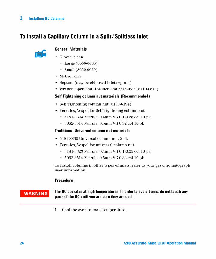
General Materials
• Gloves, clean
• Large (8650-0030)
• Small (8650-0029)
• Metric ruler
• Septum (may be old, used inlet septum)
• Wrench, open-end, 1/4-inch and 5/16-inch (8710-0510)
Self Tightening column nut materials (Recommended)
• Self Tightening column nut (5190-6194)
• Ferrules, Vespel for Self Tightening column nut
• 5181-3323 Ferrule, 0.4mm VG 0.1-0.25 col 10 pk
• 5062-3514 Ferrule, 0.5mm VG 0.32 col 10 pk
Traditional Universal column nut materials
• 5181-8830 Universal column nut, 2 pk
• Ferrules, Vespel for universal column nut
• 5181-3323 Ferrule, 0.4mm VG 0.1-0.25 col 10 pk
• 5062-3514 Ferrule, 0.5mm VG 0.32 col 10 pk
To install columns in other types of inlets, refer to your gas chromatograph user information.
Procedure
The GC operates at high temperatures. In order to avoid burns, do not touch any
WARNINGparts of the GC until you are sure they are cool.1 Cool the oven to room temperature.
7200 Accurate-Mass QTOF Operation Manual

Installing GC Columns 2
7200 Accurate-Mas
Always wear clean gloves while handling any parts that go inside the GC or analyzer
CAUTIONchambers.2 Wearing clean gloves, slide a septum, column nut, and conditioned ferrule onto the free end of the column. Figure 2 shows a traditional inlet column nut but the nut is similarly positioned for a self tightening column nut. The tapered end of the ferrule should point away from the column nut for a column attachment to an inlet.
3 Use the column cutter to score the column 2 cm from the end.
4 While holding the column against the column cutter with your thumb, break the column against the edge of the column cutter.
5 Inspect the end for jagged edges or burrs. If the break is not clean and even, repeat steps 3 and 4.
6 Wipe the outside of the free end of the column with a lint-free cloth moistened with methanol.
7 Position the septum under the column nut so that the column extends 4 to 6 mm past the end of the ferrule (Figure 3).
Figure 2 Preparing a capillary column for installation (standard inlet column nut shown)
Capillary column
Column cutter
Ferrule
Inlet column nut
Septum
s QTOF Operation Manual 27
28
2 Installing GC Columns
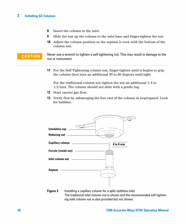
8 Insert the column in the inlet.
9 Slide the nut up the column to the inlet base and finger-tighten the nut.
10 Adjust the column position so the septum is even with the bottom of the column nut.
CAUTION Never use a wrench to tighten a self tightening nut. This may result in damage to the nut or instrument.
11 For the Self Tightening column nut, finger-tighten until it begins to grip the column then turn an additional 30 to 60 degrees until tight. For the traditional column nut tighten the nut an additional 1/4 to 1/2 turn. The column should not slide with a gentle tug.
12 Start carrier gas flow.
13 Verify flow by submerging the free end of the column in isopropanol. Look for bubbles.
Figure 3 Installing a capillary column for a split/splitless inlet The traditional inlet column nut is shown and the recommended self tighten-ing inlet column nut is also provided but not shown.
Insulation cup
Reducing nut
Capillary column
Ferrule (inside nut)
Inlet column nut
Septum
4 to 6 mm
720
0 Accurate-Mass QTOF Operation Manual
Installing GC Columns 2
To Condition a Capillary Column
7200 Accurate-Mas
Materials needed
• Carrier gas, (99.9995% pure or better)
• Wrench, open-end, 1/4-inch and 5/16-inch (8710-0510)
The use of hydrogen gas is specifically prohibited with this product.
WARNINGThe GC operates under high temperatures. To avoid burns, do not touch any GC parts
WARNINGunless you are certain they are cool.Procedure
1 Install the column in the GC inlet. (See “To Install a Capillary Column in a Split/Splitless Inlet” on page 26.)
2 Set a minimum velocity of 30 cm/s, or as recommended by the column manufacturer. Allow gas to flow through the column at room temperature for 15 to 30 minutes to remove air.
3 Program the oven from room temperature to the maximum temperature limit for the column.
4 Increase the temperature at a rate of 10 to 15 °C/min.
5 Hold at the maximum temperature for 30 minutes.
Never exceed the maximum column temperature, either in the GC/MS interface, the
CAUTIONGC oven, or the inlet.6 Set the GC oven temperature to 30 °C and wait for the GC to become ready.
7 Attach the column to the GC interface. (See “To Install a Capillary Column in the GC/MS Interface” on page 30.)
For more information about installing a capillary column, refer to Optimizing Splitless Injections on Your GC for High Performance MS Analysis, Agilent Technologies publication number 5988-9944EN.
s QTOF Operation Manual 29

2 Installing GC Columns
To Install a Capillary Column in the GC/MS Interface
30
This procedure is for the installation of a capillary column directly into the analyzer using the Agilent recommended self-tightening column nut.
Materials needed
• Column cutter, ceramic (5181-8836) or diamond (5183-4620)
• Flashlight
• Magnifying loupe
• Gloves, clean
• Large (8650-0030)
• Small (8650-0029)
• Septum (may be old, used inlet septum)
• Safety glasses
• Column install tool (G3850-60014)
Self Tightening column nut materials (Recommended)
• Self Tightening column nut (5190-5233)
• Ferrules, Vespel for Self Tightening column nut
• 5181-3323 Ferrule, 0.4 mm VG 0.1-0.25 col 10 pk
• 5062-3514 Ferrule, 0.5 mm VG 0.32 col 10 pk
Traditional MS interface nut materials
• MS Interface column nut (05988-20066)
• Ferrules, Vespel for universal column nut
• 5181-3323 Ferrule, 0.4 mm VG 0.1-0.25 col 10 pk
• 5062-3514 Ferrule, 0.5 mm VG 0.32 col 10 pk
7200 Accurate-Mass QTOF Operation Manual
Installing GC Columns 2
7200 Accurate-Mas
Procedure
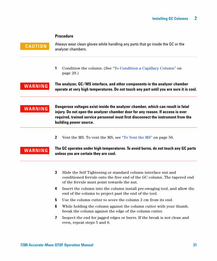
CAUTION Always wear clean gloves while handling any parts that go inside the GC or the analyzer chambers.
1 Condition the column. (See “To Condition a Capillary Column” on page 29.)
The analyzer, GC/MS interface, and other components in the analyzer chamber
WARNINGoperate at very high temperatures. Do not touch any part until you are sure it is cool.WARNING Dangerous voltages exist inside the analyzer chamber, which can result in fatal injury. Do not open the analyzer chamber door for any reason. If access is ever required, trained service personnel must first disconnect the instrument from the building power source.
2 Vent the MS. To vent the MS, see “To Vent the MS” on page 56.
The GC operates under high temperatures. To avoid burns, do not touch any GC parts
WARNINGunless you are certain they are cool.3 Slide the Self Tightening or standard column interface nut and conditioned ferrule onto the free end of the GC column. The tapered end of the ferrule must point towards the nut.
4 Insert the column into the column install pre-swaging tool, and allow the end of the column to project past the end of the tool.
5 Use the column cutter to score the column 2 cm from its end.
6 While holding the column against the column cutter with your thumb, break the column against the edge of the column cutter.
7 Inspect the end for jagged edges or burrs. If the break is not clean and even, repeat steps 5 and 6.
s QTOF Operation Manual 31

32
2 Installing GC Columns
8 Wipe the outside of the free end of the column with a lint-free cloth moistened with methanol.
9 Slide the column so that the end projects 4–5 mm past the end of the column install pre-swaging tool.
10 For the Self Tightening column nut, finger-tighten until it begins to grip the column then turn an additional 30 to 60 degrees until tight. For the traditional column nut, tighten the nut an additional 1/4 to 1/2 turn. The column should not slide with a gentle tug.
11 Loosen the column nut and remove the column from the tool.
12 Slide the column into the GC/MS interface.
13 Hand-tighten the nut. Ensure the position of the column does not change as you tighten the nut.
14 Check the GC oven to be sure that the column does not touch the oven walls.
15 Check the nut’s tightness after one or two heat cycles; retighten as appropriate.
7200 Accurate-Mass QTOF Operation Manual

Agilent 7200 Accurate-Mass Quadrupole Time-of-Flight GC/MS System Operation Manual
3Operating in Electron Impact (EI) Mode
Operating the MS from the Data System 34
The GC/MS Interface 35
Before You Turn On the MS 37
Pumping Down 38
Controlling Temperatures 38
Controlling Column Flow 38
Controlling Collision Cell Flow 39
Venting the MS 39
Typical Vacuum Pressures in EI Mode 40
To Set Monitors for Temperature and Vacuum Status 41
To Set the MS Analyzer Temperature 43
To Set the GC/MS Interface Temperature from the MassHunter Workstation 45
To Calibrate the Column 46
To Configure the Collision Cell Gas 48
To Set the Collision Cell Gas Flow Rate 49
To Autotune the MS for EI Mode 50
To Remove the Upper RIS Cover 52
To Open the Analyzer Cover for Access to the Analyzer Sideplate 53
To Pump Down the MS 54
To Vent the MS 56
This chapter will explain how to perform some routine operating procedures for the 7200 Accurate-Mass Q-TOF GC/MS in EI mode.
33Agilent Technologies

3 Operating in Electron Impact (EI) Mode
Operating the MS from the Data System
34
The Agilent MassHunter Data Acquisition Workstation automates tasks such as pumping down, removing the ion source, monitoring settings, setting temperatures, tuning, and venting the MS. These tasks are described in this chapter. Additional information is described in the manuals and online help supplied with the MassHunter Workstation software.
The software and firmware are revised periodically. If the steps in these procedures do
CAUTIONnot match your MassHunter Workstation software, refer to the manuals and online help supplied with the software for more information.Your G3851BA 7200 Q-TOF GC/MS provides the capability of operating in either EI or CI modes, using the new RIS technology. You must specify the type of ionization you are using in the Acquisition software tune file used by your method.
7200 Accurate-Mass QTOF Operation Manual

Operating in Electron Impact (EI) Mode 3
The GC/MS Interface
7200 Accurate-Mas
The GC/MS interface (Figure 4) is a heated conduit into the MS for the capillary column. The interface is bolted onto the right side of the front analyzer chamber and has an O-ring seal. It has a protective insulated cover that should be left in place.
One end of the GC/MS interface passes through the side of the gas chromatograph and extends into the GC oven. This end is threaded to allow connection of the column with a nut and ferrule. The other end of the interface fits into the ion source. The last 4 to 5 mm of the capillary column extends past the end of the guide tube and into the ionization chamber. When changing the removable ion source, the interface is automatically retracted from the ion source by the MassHunter software. This allows the ion source to slide freely in and out of the analyzer chamber.
The GC/MS interface is heated by an electric cartridge heater. Normally, the heater is powered and controlled by the Thermal Aux #2 heated zone of the GC. The interface temperature can be set from the MassHunter Workstation or from the gas chromatograph keypad. A sensor (thermocouple) in the interface monitors the temperature.
The GC/MS interface generally operates in the 250 to 350 °C range. Subject to that restriction, the interface temperature should be slightly higher than the maximum GC oven temperature, but never higher than the maximum column temperature.
See also
“To Install a Capillary Column in the GC/MS Interface” on page 30.
The GC/MS interface operates at high temperatures. If you touch it when it is hot, it
WARNINGwill burn you.s QTOF Operation Manual 35

3 Operating in Electron Impact (EI) Mode
Figure 4 The GC/MS interface
Column end protrudes 4 to 5 mm into the ionization chamber.
IRM calibrant in
MS GC oven
Spring-loaded tip seal entrance to ion source
Column not shown
Heater sensor assembly
Column nut
36
7200 Accurate-Mass Q TOF Op eration Manual
Operating in Electron Impact (EI) Mode 3
Before You Turn On the MS
7200 Accurate-Mas
Verify the following before you turn on or attempt to operate the MS.
• All vacuum seals and fittings must be in place and fastened correctly. The analyzer plate thumbscrew should be unfastened, unless hazardous carrier or reagent gases are being used.
• The MS is connected to a grounded power source.
• The GC/MS interface extends into the GC oven.
• A conditioned capillary column is installed in the GC inlet and in the GC/MS interface.
• The GC is on, but the heated zones for the GC/MS interface, the GC inlet, and the oven are off.
• Carrier gas of at least 99.9995% purity is plumbed to the GC with the recommended traps.
• The use of hydrogen gas is specifically prohibited with this product.
• The foreline pump exhaust is properly vented.
The exhaust from the foreline pump contains solvents and the chemicals you are
WARNINGanalyzing. The standard foreline pump, also exhausts traces of pump oil. If you are using toxic solvents or analyzing toxic chemicals, attach a hose (11-mm id) to the oil mist filter to take the foreline pump exhaust outside or to a fume (exhaust) hood. Be sure to comply with local regulations. The oil mist filter supplied with the standard pump stops only pump oil. It does not trap or filter out toxic chemicals.The use of hydrogen gas is specifically prohibited with this product.
WARNINGs QTOF Operation Manual 37

3 Operating in Electron Impact (EI) Mode
Pumping Down
38
Pumping down is only required if the analyzer was vented. It is not required for changing the ion source.
The data system helps you pump down the MS. The process is mostly automated. When you turn on the main power switch (while pressing on the analyzer sideplate), the MS pumps down by itself. The data system software monitors and displays system status during pumpdown. When the pressure is low enough, the program turns on the ion source and mass filter heaters and prompts you to turn on the GC/MS interface heater. The MS will shut down if it cannot pump down correctly.
Using the MS monitors, the data system can display:
• Motor speed for each MS turbo pump
• Analyzer chamber pressure (vacuum)
• Quadrupole and ion source temperatures
Controlling Temperatures
MS temperatures are controlled through the data system. The MS has independent heaters and temperature sensors for the ion source and the quadrupole mass filter. You can adjust the setpoints and view these temperatures from the data system
The GC/MS interface heater is powered and controlled by the Thermal Aux #2 heated zone of the GC. The GC/MS interface temperature can be set and monitored from the data system or from the GC keypad.
Controlling Column Flow
Carrier gas flow is controlled by column inlet pressure in the GC. For a given inlet pressure, column flow will decrease as the GC oven temperature increases. With electronic pneumatic control (EPC) and the column mode set to Constant Flow, the same column flow is maintained regardless of temperature.
7200 Accurate-Mass QTOF Operation Manual

Operating in Electron Impact (EI) Mode 3
7200 Accurate-Mas
The MS can be used to measure actual column flow. You inject a small amount of air or other unretained chemical and time how long it takes to reach the MS. With this time measurement, you can calculate the column flow. See “To Calibrate the Column” on page 46.
Controlling Collision Cell Flow
The collision cell gas flow rate is controlled by an EPC module located in the GC. The collision cell gas flow consists of nitrogen. The gas pressure at the EPC outlet controls the flow of the gas. This pressure is controlled by the MassHunter Data Acquisition Workstation or directly at the GC keypad. See “To Set the Collision Cell Gas Flow Rate” on page 49.
Venting the MS
A program in the data system automates the venting process. It turns off the GC and MS heaters and the turbo pump at the correct time.
The Fast Vent feature loads a user-defined GC method that sets an oven temperature, turns off the transfer line heater and sets the column flow to a user predefined level.
The MS will be damaged by incorrect venting. A turbo pump will be damaged if it is vented while spinning at more than 50% of its normal operating speed.
The use of hydrogen gas is specifically prohibited with this product.
WARNINGNever vent the MS by allowing air in through either end of the foreline hose. Use the
CAUTIONvent valve or remove the column nut and column.Do not exceed the maximum recommended total gas flow. See Table 2.
s QTOF Operation Manual 39

3 Operating in Electron Impact (EI) Mode
Typical Vacuum Pressures in EI Mode
40
The largest influences on operating pressure in EI mode are the carrier gas (column) and collision cell gas flows. Table 3 lists typical pressures for various helium and nitrogen collision cell gas flows. These pressures are approximate and will vary from instrument to instrument by as much as 30%.
Table 3 Influence of carrier and collision cell gas flows on vacuum
CC Gas On N2 = 1.5 mL/min
CC Gas Off
Column Flow (mL/min) Rough Vac Quad Vac TOF Vac Rough Vac Quad Vac TOF Vac
0.5 1.16 * 10-1 3.41 * 10-5 4.20* 10-7 8.29 * 10-2 3.17 * 10-7 2.15 * 10-7
0.7 1.18 * 10-1 3.41 * 10-5 4.20 * 10-7 8.67 * 10-2 3.45 * 10-7 2.15 * 10-7
1 1.22 * 10-1 3.43 * 10-5 4.22 * 10-7 9.17 * 10-2 3.79 * 10-7 2.16 * 10-7
1.2 1.24 * 10-1 3.43 * 10-5 4.22 * 10-7 9.49 * 10-2 4.06 * 10-7 2.16 * 10-7
2 1.32 * 10-1 3.44 * 10-5 4.22 * 10-7 1.07 * 10-1 5.17 * 10-7 2.17 * 10-7
3 1.42 * 10-1 3.44 * 10-5 4.25 * 10-7 1.19 * 10-1 6.51 * 10-7 2.20 * 10-7
4 1.50 * 10-1 3.46 * 10-5 4.27 * 10-7 1.29 * 10-1 7.84 * 10-7 2.21 * 10-7
If the pressure is consistently higher than those listed, refer to the online help in the MassHunter Workstation software for information on troubleshooting air leaks and other vacuum problems.
7200 Accurate-Mass QTOF Operation Manual

Operating in Electron Impact (EI) Mode 3
To Set Monitors for Temperature and Vacuum Status
7200 Accurate-Mas
A monitor displays the current value of a single instrument parameter. They can be added to the standard instrument control window. Monitors can be set to change color if the actual parameter varies beyond a user-determined limit from its setpoint.
Procedure
1 Select Instrument > Edit Monitors to display the Select Monitors dialog box. See Figure 5.
Figure 5 Select Monitors dialog box
s QTOF Operation Manual 41

42
3 Operating in Electron Impact (EI) Mode
2 In the Available Monitors column, select a monitor and click the Add button to move the selected monitor to the Selected Monitors column.
3 Select any other monitors you want and add them to the Selected Monitors column.
4 Click OK. The new monitors will be stacked on top of each other in the lower right corner of the Instrument Control window.
5 Select Window > Arrange Monitors, or click and drag each monitor to the desired position. See Figure 6 for one way of arranging the monitors.
Figure 6 Arranging monitors
6 To make the new settings part of the method, select Save from the Method menu.
7200 Accurate-Mass QTOF Operation Manual

Operating in Electron Impact (EI) Mode 3
To Set the MS Analyzer Temperature
7200 Accurate-Mas
Setpoints for the MS ion source and quad temperatures are stored in the current tune file. When a method is loaded, the setpoints in the tune file associated with that method are downloaded automatically.
Procedure
1 In Instrument Control panel, select the MS Tune icon to display the Tune dialog box. Select the Manual Tune tab then select the Ion Source tab to display the ion source parameters.
2 Enter the temperature setpoint in the Source Temp field. See Table 4 for recommended setpoints.
3 Select the Quadrupole tab to display the MS parameters.
4 Enter the temperature setpoint in the Quad Temp field. See Table 4 for recommended setpoints.
5 Select the Files and Reports tab then click the Save button to save the tune file with these changes.
Table 4 Recommended temperature settings
Zone EI operation
MS Source 230 °C
MS Quad 150 °C
s QTOF Operation Manual 43

44
3 Operating in Electron Impact (EI) Mode
Figure 7 Setting temperatures
The GC/MS interface, ion source, and the MS quadrupole heated zones interact. The analyzer heater may not be able to accurately control temperature if the setpoint for one zone is much different from that of an adjacent zone.
The software will not allow you to exceed 200 °C for the quadrupole, or 350 °C for
WARNINGthe ion source.7200 Accurate-Mass QTOF Operation Manual

Operating in Electron Impact (EI) Mode 3
To Set the GC/MS Interface Temperature from the MassHunter Workstation
7200 Accurate-Mas
You can also use the GC Control panel to perform this task.
Procedure
1 Select Instrument > GC Parameters from the Instrument Control panel.
2 Click the Aux Heaters icon to edit the interface temperature (Figure 8). This example has the GC/MS interface temperature configured as Thermal Aux 2.
Figure 8 Setting the interface temperature
Ensure that the carrier gas is turned on and the column has been purged of air before
CAUTIONheating the GC/MS interface or the GC oven.s QTOF Operation Manual 45

46
3 Operating in Electron Impact (EI) Mode
When setting the GC/MS interface temperature, never exceed the maximum for your
CAUTIONcolumn.3 Click the heater On check box and enter the setpoint in the Value °C column. The typical setpoint is 280 °C. The limits are 0 °C to 400 °C. A setpoint below ambient temperature turns off the interface heater.
4 Click Apply to download setpoints or click OK to download setpoints and close the window.
5 To make the new settings part of the method, select Save from the Method menu.
To Calibrate the Column
Capillary columns must be calibrated prior to use with the MS.
Procedure
1 Set Data Acquisition for splitless manual injection and set up a real time plot to monitor m/z 28.
2 Press [Prep Run] on the GC keypad.
3 Inject 1 µL of air into the GC inlet and press [Start Run]
4 Wait until a peak elutes at m/z 28. Note the retention time.
5 In the Instrument Control panel, select .
6 Select the Configuration tab.
7 Select the Column tab and from the table, then select the column to be calibrated and click Calibrate.
8 Select the Calc Length button.
9 In the Calculate Column Length dialog box, enter the recorded retention time in the Holdup Time of an Unretained Peak field.
10 Verify that the other parameters listed (temperature, inlet and outlet pressures, and gas type) are those used in the method to determine the holdup time. Change any parameters that are different than those used in your method.
7200 Accurate-Mass QTOF Operation Manual

Operating in Electron Impact (EI) Mode 3
7200 Accurate-Mas
11 When the new column length appears, click OK to save the changes.
12 Click OK on the Calibrate Columns screen to save the calibration.
Figure 9 Calculate Column Length dialog box
s QTOF Operation Manual 47

3 Operating in Electron Impact (EI) Mode
To Configure the Collision Cell Gas
48
1 From the MassHunter Data Acquisition Workstation Instrument Control panel,
select .
2 Click the Configuration icon and select the Modules tab to display the screen. See Figure 10.
3 From the Collision Cell EPC drop-down menu, select N2 as the collision cell
Figure 10 Configure the collision cell gas
gas.
4 Click OK to save the configuration.
7200 Accurate-Mass QTOF Operation Manual

Operating in Electron Impact (EI) Mode 3
To Set the Collision Cell Gas Flow Rate
7200 Accurate-Mas
1 From the MassHunter Data Acquisition Workstation Instrument Control panel, select Instrument > GC Parameters.
2 Click the Columns icon to display control parameter entry screen for column and Aux flow modules. See Figure 11.
3 Select Collision Cell EPC in the Selection list.
4 Enter the required gas flow rates in the appropriate fields.
5 Click the N2 Collision Gas check box to allow the N2 collision gas flow.
6 Click Apply to download the setpoints or OK to download the setpoints and close the window.
7 To make the new settings part of the method, select Save from the Method menu.
Figure 11 Setting the collision cell gas flow rate
s QTOF Operation Manual 49

3 Operating in Electron Impact (EI) Mode
To Autotune the MS for EI Mode
50
The MS can be tuned using the MassHunter Workstation software.
Procedure
1 Set the system to the same conditions (GC oven temperature and column flow, and MS analyzer temperature) that will be used for data acquisition.
2 In the Instrument Control panel, click the MS Tune icon to display the GC/Q-TOF Tune dialog box.
3 The current tune file is displayed in the upper left corner of the GC/Q-TOF Tune dialog box. Verify that the correct tune file is loaded.
4 If necessary, load a new tune file by clicking on the Files and Report tab then click on the Load button in the Tune File area. Select a tune file and click the OK button.
The tune file must match the type of ion source in the analyzer. If you are using an EI ion source, select a tune file created for an EI ion source.
5 Click the Autotune tab and select the Tune from default settings check box if you are restarting the system after a system vent, major servicing, or a power outage. If you clear the Tune from default settings box, the autotune process starts using the previous tune values.
6 Select Save tune file when done check box to save the new tune parameters generated by the autotune. Do not select this item if you want to review the autotune report before saving the newly generated tune parameters.
7 Select the Print autotune report check box to automatically print a tune report.
8 Click the Autotune button to start the autotune. The Status line displays the current step in the autotune process and the plot of the tuned parameter for that step is shown in the top graph. If specified above, at the completion of the autotune, a Tune Report is printed.
To stop the autotune before it completes the automatic parameter selection, click the Abort Tune button. The parameters from the last successful autotune are used.
9 Review the Tune Report. If the results are acceptable and you did not select the Save tune file when done check box, save the autotune by clicking the Files and Report tab, then click the Save button.
7200 Accurate-Mass QTOF Operation Manual

Operating in Electron Impact (EI) Mode 3
7200 Accurate-Mas
See the manuals or online help provided with your MassHunter Data Acquisition Workstation software for additional information about tuning.
Figure 12 EI Autotune
s QTOF Operation Manual 51
3 Operating in Electron Impact (EI) Mode
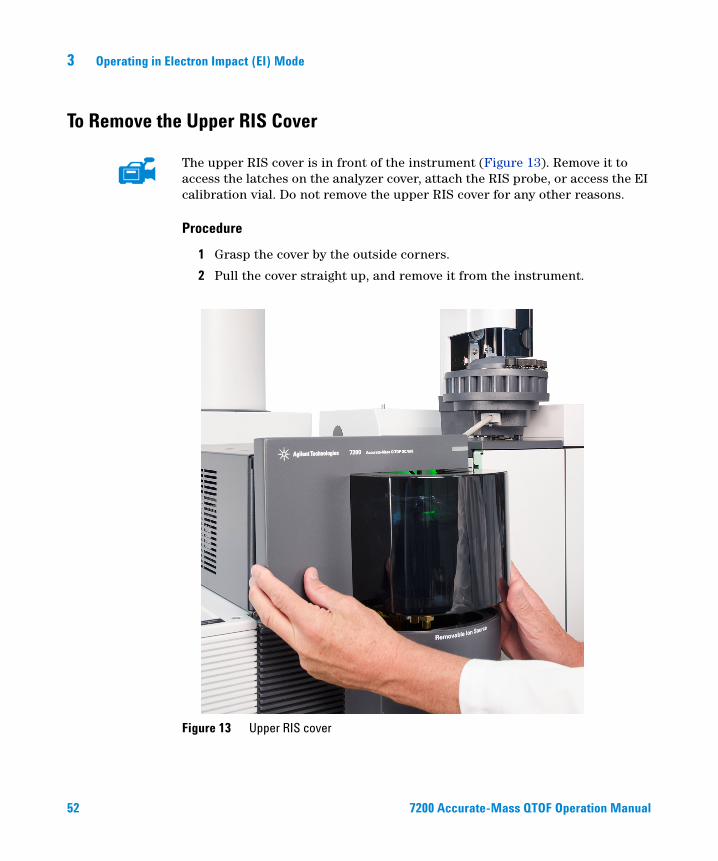
To Remove the Upper RIS Cover
52
The upper RIS cover is in front of the instrument (Figure 13). Remove it to access the latches on the analyzer cover, attach the RIS probe, or access the EI calibration vial. Do not remove the upper RIS cover for any other reasons.
Procedure
1 Grasp the cover by the outside corners.
2 Pull the cover straight up, and remove it from the instrument.
Figure 13 Upper RIS cover
7200 Accurate-Mass QTOF Operation Manual

Operating in Electron Impact (EI) Mode 3
To Open the Analyzer Cover for Access to the Analyzer Sideplate
7200 Accurate-Mas
Open the analyzer cover (Figure 14) to access the analyzer sideplate only. This is necessary during pump down or to access the analyzer sideplate thumbscrews. You should not open the analyzer cover for any other reason.
Procedure
1 Remove the upper RIS cover to expose the analyzer cover latches. See “To Remove the Upper RIS Cover” on page 52.
2 Open the latches on the analyzer cover at the front of the instrument.
3 Swing the analyzer cover open.
Figure 14 Covers
Analyzer cover
Upper RIS cover
s QTOF Operation Manual 53

3 Operating in Electron Impact (EI) Mode
To Pump Down the MS
54
Ensure your MS meets all the conditions listed in the introduction to this chapter
WARNINGbefore starting up and pumping down the MS. Failure to do so can result in personal injury.WARNING The use of hydrogen gas is specifically prohibited with this product.
WARNING Dangerous voltages exist inside the analyzer chamber, which can result in fatal injury. Do not open the analyzer chamber door for any reason. If access is ever required, trained service personnel must first disconnect the instrument from the building power source.
Procedure
1 Open the analyzer cover to access the analyzer quad driver board. See “To Open the Analyzer Cover for Access to the Analyzer Sideplate” on page 53.
2 Plug the power cord into a grounded electrical outlet.
3 Turn on the Q-TOF power switch (Figure 14).
4 Press lightly on the metal box on the quad driver board to ensure a correct seal.
Do not push on the filament board safety cover while pressing on the analyzer board.
CAUTIONThis cover was not designed to withstand this type of pressure.The foreline pump will make a gurgling noise. This noise should stop within a minute. If the noise continues, there is a large air leak in your system, probably at the sideplate seal or the interface column nut.
5 Start the MassHunter Data Acquisition program. If the Q-TOF was configured for both an EI and a CI ion source, you are prompted for the ion source type that is currently installed. Click on an EI or CI ion source type if prompted.
6 Select the MS Tune icon from the Instrument Control panel.
7 Select the Vacuum Control tab.
7200 Accurate-Mass QTOF Operation Manual

Operating in Electron Impact (EI) Mode 3
7200 Accurate-Mas
8 Click the Pumpdown button.
Figure 15 Vacuum Control tab
Do not turn on any GC heated zones until carrier gas flow is on. Heating a column with
CAUTIONno carrier gas flow will damage the column.Within 10 to 15 minutes, the turbo pump speed should be up to 80% (Figure 15). The pump speed should eventually reach 95%. If these conditions are not met, the MS electronics will shut off the foreline pump. In order to recover from this condition, you must power cycle the MS. If the MS does not pump down correctly, see the manual or online help for information on troubleshooting air leaks and other vacuum problems.
9 Turn on the carrier gas flow after the vacuum pumps have been running for 15 minutes.
10 When prompted, turn on the GC/MS interface heater and GC oven. Click OK when you have done so. The software will turn on the ion source and mass filter (quad) heater. The temperature setpoints are stored in the current autotune file.
11 After the message Okay to run appears, wait 2 hours for the MS to reach thermal equilibrium. Data acquired before the MS has reached thermal equilibrium may not be reproducible.
12 Tune the MS. (See “To Autotune the MS for EI Mode” on page 50 or “To Perform a CI Autotune” on page 72.)
s QTOF Operation Manual 55

3 Operating in Electron Impact (EI) Mode
To Vent the MS
56
Procedure
1 Click the MS Tune icon from the Instrument Control panel.
2 Select the Vacuum Control tab. See Figure 15.
3 Set the GC/MS interface heater and the GC oven temperatures to ambient (room temperature).
4 When the GC temperatures have reached 30 °C, turn off the flow of carrier gas.
5 Click the Vent button.
The use of hydrogen gas is specifically prohibited with this product.
WARNINGBe sure the GC oven and the GC/MS interface are cool before turning off carrier gas
CAUTIONflow.6 Turn off the MS by pressing the power switch. (See Figure 1.)
7 Unplug the MS power cord.
WARNING Allow the analyzer to cool to near room temperature before touching it.
When the MS is vented, do not put the Workstation into Instrument Control view.
CAUTIONDoing so will turn on the interface heater, which can damage the column.7200 Accurate-Mass QTOF Operation Manual

Agilent 7200 Accurate-Mass Quadrupole Time-of-Flight GC/MS System Operation Manual
4Operating in Chemical Ionization (CI) Mode
Setting Up Your MS to Operate in CI Mode 58
The GC/MS Interface 59
Operating the CI MS 61
High Vacuum Pressure in CI Mode 62
Other Reagent Gases 63
CI Autotune 65
The Flow Control Module 66
To Switch from the EI Mode to CI Mode 67
To Operate the Reagent Gas Flow Control Module 69
To Set a Reagent Gas Flow 71
To Perform a CI Autotune 72
This chapter provides information and instructions for operating the 7200 Q-TOF GC/MS system in Chemical Ionization (CI) mode. Most of the information in the preceding chapter is also relevant.
Most of the material is related to methane chemical ionization but one section discusses the use of other reagent gases.
The software contains instructions for setting the reagent gas flow and for performing CI autotunes. Autotunes are provided for positive CI (PCI) with methane reagent gas and for negative CI (NCI) with any reagent gas.
57Agilent Technologies

4 Operating in Chemical Ionization (CI) Mode
Setting Up Your MS to Operate in CI Mode
58
Setting up your MS for operation in CI mode requires special care to avoid contamination and air leaks.
• Always use the highest purity methane (and other reagent gases, if applicable). Methane must be at least 99.9995% pure.
• Always verify the MS is performing well in EI mode before switching to CI.
• Ensure the CI ion source is installed.
• Ensure the reagent gas plumbing has no air leaks. This is determined in PCI mode, checking for m/z 32 after the methane pretune.
• Ensure the reagent gas inlet line is equipped with gas purifiers (not applicable for ammonia).
7200 Accurate-Mass QTOF Operation Manual

Operating in Chemical Ionization (CI) Mode 4
The GC/MS Interface
7200 Accurate-Mas
The GC/MS interface (Figure 16) is a heated conduit into the MS for the capillary column. It is bolted onto the right side of the analyzer chamber, with an O-ring seal and has a protective insulated cover which should be left in place.
One end of the interface passes through the side of the GC and extends into the oven. It is threaded to allow connection of the column with a nut and ferrule. The other end of the interface fits into the ion source. The last 4 to 5 mm of the capillary column extend past the end of the guide tube and into the ionization chamber. When changing the removable ion source, the interface is automatically retracted from the ion source with the MassHunter software. This allows the source to slide freely in and out of the analyzer chamber.
For CI operating mode, reagent gas is also plumbed into the interface. A tip seal keeps reagent gases from leaking out around the tip. The reagent gas enters the interface body and mixes with carrier gas and sample in the ion source.
The GC/MS interface is heated by an electric cartridge heater. Normally, the heater is powered and controlled by the Thermal Aux #2 heated zone of the GC. The interface temperature can be set from the MassHunter Workstation or from the gas chromatograph keypad. A sensor (thermocouple) in the interface monitors the temperature.
This interface is also be used for EI operation.
The interface should be operated in the 250 ° to 350 °C range. Subject to that restriction, the interface temperature should be slightly higher than the maximum GC oven temperature, but never higher than the maximum column temperature.
See Also
“To Install a Capillary Column in the GC/MS Interface” on page 30.
s QTOF Operation Manual 59

60
4 Operating in Chemical Ionization (CI) Mode
CAUTION Never exceed the maximum column temperature, either in the GC/MS interface, the GC oven, or the inlet.
WARNING The GC/MS interface operates at high temperatures. If you touch it when it is hot, it will burn you.
Figure 16 The GC/MS interface
Reagent gas and IRM calibrant in
MS GC oven
Spring-loaded tip seal entrance to ion source
Column not shown
Heater sensor assembly
Column nut
7200 Accurate-Ma
ss QTOF Operation Manual
Operating in Chemical Ionization (CI) Mode 4
Operating the CI MS
7200 Accurate-Mas
Operating your GC/MS in the CI mode is slightly more complicated than operating in the EI mode. After tuning, gas flow, temperatures (Table 5), and electron energy may need to be optimized for your specific analyte.
Table 5 Temperatures for CI operation
Ion source Analyzer GC/MS interface
PCI 300 °C 150 °C 280 °C
NCI 150 °C 150 °C 280 °C
Start the system in CI mode
When starting up the system you may begin in either PCI or NCI mode. Depending upon the application, use the following reagent gas flowrates during system startup:
• PCI mode set reagent gas flow to 20 (1 mL/min)
• NCI mode set reagent gas flow to 40 (2 mL/min)
s QTOF Operation Manual 61

4 Operating in Chemical Ionization (CI) Mode
High Vacuum Pressure in CI Mode
62
The largest influences on operating pressure in CI mode are the reagent and collision cell gas flows. Table 6 lists typical pressures for various reagent gas flows, depending upon the collision cell gas flowrate. Familiarize yourself with the measurements on your system under operating conditions and watch for changes that may indicate a vacuum or gas flow problem. Measurements will vary by as much as 30% from one MS to the next.
Analyzer vacuum with reagent gas flowing
Note that the mass flow controller (MFC) is calibrated for methane and the vacuum gauge is calibrated for nitrogen, so these measurements are not accurate, but are intended as a guide to typical observed readings (Table 6). They were taken with the following set of conditions. Note that these are typical PCI temperatures:
Source temperature 230 °CQuad temperature 150 °CInterface temperature 280 °CInlet 250 °COven 100 °CHelium carrier gas flow 1 mL/min
Table 6 Typical analyzer vacuum with reagent gas flow
Collision cell gas flow onN2 = 1.5 mL/min
Collision cell gas flow offN2 = 0 mL/min
MFC (%) Rough Pump (mTorr)
Quadrupole (Torr)
Flight Tube (Torr)
Rough Pump (mTorr)
Quadrupole (Torr)
Flight Tube (Torr)
0 1.36e+02 3.62e-05 3.35e-07 9.13e+01 5.98e-07 1.64e-07
10 1.36+02 3.62e-05 3.37e-07 1.14e+01 1.27e-06 1.65e-07
15 1.43+02 3.66e-05 3.37e-07 1.23e+01 1.62e-06 1.67e-07
20 1.5+02 3.71e-05 3.39e-07 1.31e+01 1.96e-06 1.67e-07
25 1.57+02 3.73e-05 3.41e-07 1.39e+01 2.32e-06 1.70e-07
30 1.63+02 3.77e-05 3.41e-07 1.46e+01 2.64e-06 1.71e-07
35 1.69+02 3.81e-05 3.41e-07 1.52e+01 3.00e-06 1.71e-07
40 1.74+02 3.83e-05 3.43e-07 1.58e+01 3.34e-06 1.72e-07
7200 Accurate-Mass QTOF Operation Manual

Operating in Chemical Ionization (CI) Mode 4
Other Reagent Gases
7200 Accurate-Mas
This section describes the use of isobutane or ammonia as the reagent gas. You should be familiar with operating the CI-equipped 7200 Q-TOF GC/MS with methane reagent gas before attempting to use other reagent gases.
CAUTION Do not use nitrous oxide as a reagent gas. It radically shortens the life span of the filament.
Changing the reagent gas from methane to either isobutane or ammonia changes the chemistry of the ionization process and yields different ions. The principal chemical ionization reactions encountered are described in general in the Agilent 7200 Accurate-Mass Q-TOF GC/MS Concept Guide. If you are not experienced with chemical ionization, we suggest reviewing that material before you proceed.
Isobutane CI
Isobutane (C4H10) is commonly used for chemical ionization when less fragmentation is desired in the chemical ionization spectrum. This is because the proton affinity of isobutane is higher than that of methane; hence less energy is transferred in the ionization reaction.
Addition and proton transfer are the ionization mechanisms most often associated with isobutane. The sample itself influences which mechanism dominates.
Ammonia CI
Ammonia (NH3) is commonly used for chemical ionization when less fragmentation is desired in the chemical ionization spectrum. This is because the proton affinity of ammonia is higher than that of methane; hence less energy is transferred in the ionization reaction.
Because many compounds of interest have insufficient proton affinities, ammonia chemical-ionization spectra often result from the addition of NH4
+ and then, in some cases, from the subsequent loss of water. Ammonia reagent ion spectra have principal ions at m/z 18, 35, and 52, corresponding to NH4
+, NH4(NH3)+, and NH4(NH3)2
+.
s QTOF Operation Manual 63

64
4 Operating in Chemical Ionization (CI) Mode
CAUTION Use of ammonia affects the maintenance requirements of the MS. See Chapter 6, “General Maintenance”” for more information.
CAUTION The pressure of the ammonia supply must be less than 5 psig. Higher pressures can result in ammonia condensing from a gas to a liquid.
Always keep the ammonia tank in an upright position, below the level of the flow module. Coil the ammonia supply tubing into several vertical loops by wrapping the tubing around a can or bottle. This will help keep any liquid ammonia out of the flow module.
Ammonia tends to break down vacuum pump fluids and seals. Ammonia CI makes more frequent vacuum system maintenance necessary. (See the Agilent 7200 Q-TOF GC/MS Troubleshooting and Maintenance Manual.)
CAUTION When running ammonia for 5 or more hours a day, the foreline pump must be ballasted (flushed with air) for at least 1 hour a day to minimize damage to pump seals. Always purge the MS with methane after flowing ammonia.
Frequently, a mixture of 5% ammonia and 95% helium or 5% ammonia and 95% methane is used as a CI reagent gas. This is enough ammonia to achieve good chemical ionization while minimizing its negative effects.
Carbon dioxide CI
Carbon dioxide is often used as a reagent gas for CI. It has obvious advantages of availability and safety.
7200 Accurate-Mass QTOF Operation Manual

Operating in Chemical Ionization (CI) Mode 4
CI Autotune
7200 Accurate-Mas
After the reagent gas flow is set, the lenses and electronics of the MS should be tuned which is a good starting point for developing your application settings. Typical CI application settings are shown inTable 7. Perfluoro-5,8-dimethyl-3,6,9-trioxidodecane (PFDTD) is used as the calibrant. Instead of flooding the entire vacuum chamber, the PFDTD is introduced directly into the ionization chamber through the GC/MS interface by means of the gas flow control module. There are no tune performance criteria. If CI autotune completes, it passes.
Always verify MS performance in EI before switching to CI operation.
CAUTIONCI application settings
Table 7 TypicalParameter Methane Isobutane Ammonia EI
Ion polarity Positive Negative Positive Negative Positive Negative N/A
Emission 150 μA 50 μA 150 μA 50 μA 150 μA 50 μA 35 μA
Electron energy 150 eV 150 eV 150 eV 150 eV 150 eV 150 eV 70 eV
Filament 1 1 1 1 1 1 1 or 2
Repeller 3 V 3 V 3 V 3 V 3 V 3 V 30 V
Ion focus 130 V 130 V 130 V 130 V 130 V 130 V 90 V
Entrance lens offset
20 V 20 V 20 V 20 V 20 V 20 V 25 V
Shutoff valve Open Open Open Open Open Open Closed
Suggested flow 20% 40% 20% 40% 20% 40% N/A
Source temp 250 °C 150 °C 250 °C 150 °C 250 °C 150 °C 230 °C
Quad temp 150 °C 150 °C 150 °C 150 °C 150 °C 150 °C 150 °C
Interface temp 280 °C 280 °C 280 °C 280 °C 280 °C 280 °C 280 °C
Autotune Yes Yes No Yes No Yes Yes
N/A Not available
s QTOF Operation Manual 65

4 Operating in Chemical Ionization (CI) Mode
The Flow Control Module
66
The CI reagent gas flow control module regulates the flow of reagent gas into the CI GC/MS interface. The flow module consists of a mass flow controller (MFC), gas select valves, CI calibration valve, shutoff valve, control electronics, and plumbing.
The instrument provides Swagelok inlet fittings for connecting the CI reagent gas. The software refers to it as CI reagent gas. Supply reagent gases at 20 to 25 psi (138 to 172 kPa) for Methane.
7200 Accurate-Mass QTOF Operation Manual

Operating in Chemical Ionization (CI) Mode 4
To Switch from the EI Mode to CI Mode
7200 Accurate-Mas
Always verify GC/MS performance in EI before switching to CI operation.
CAUTIONAlways wear clean gloves while touching the analyzer or any other parts that go inside
CAUTIONthe analyzer chamber.Procedure
1 Change the source. See “To Change the Ion Source” on page 78.
2 Load a suitable PCI or NCI method for use with the CI source.
3 Click the MS Tune icon in the Instrument Control panel to display the Tune dialog box and select the Autotune tab.
The method selects PCI or NCI autotune and the correct reagent gas.
4 Select the Tune from default settings check box because you have changed the ion source.
5 Select Print autotune report check box to automatically print a tune report.
6 Click the Autotune button to start the autotune. At the completion of the autotune, a Tune Report is printed.
7 Review the Tune Report. If the results are acceptable, save the autotune by clicking the Files and Report tab, then click the Save button.
Table 8 Default Tune Control Limits, used by CI autotune only
Reagent gas Methane Ammonia
Ion polarity Positive Negative Positive Negative
Abundance target 1x10⁶ 1x10⁶ N/A 1x10⁶
Peakwidth target 0.7 0.7 N/A 0.7
Maximum repeller 4 4 N/A 4
s QTOF Operation Manual 67

68
4 Operating in Chemical Ionization (CI) Mode
Notes for Table 8:
• N/A Not available.
• Abundance target Adjust higher or lower to get desired signal abundance. Higher signal abundance also gives higher noise abundance.
• Peakwidth target Higher peakwidth values give better sensitivity, lower values give better resolution.
• Maximum emission current Optimum emission current maximum for NCI is very compound-specific and must be selected empirically. Optimum emission current for pesticides, for example, may be about 200 µA.
Maximum emission current, µA
240 50 N/A 50
Max electron energy, eV 240 240 N/A 240
Table 8 Default Tune Control Limits, used by CI autotune only (continued)
Reagent gas Methane Ammonia
7200 Accurate-Mass QTOF Operation Manual

Operating in Chemical Ionization (CI) Mode 4
To Operate the Reagent Gas Flow Control Module
7200 Accurate-Mas
Procedure
1 In Instrument Control panel, select the MS Tune icon to display the GC/Q-TOF Tune dialog box. Select the Manual Tune tab then select the Ion Source tab to display the ion source parameters.
Figure 17 CI flow control
s QTOF Operation Manual 69

70
4 Operating in Chemical Ionization (CI) Mode
2 Use the parameters in the CI Reagent Gas Control area to control reagent gas flow.
CI Reagent - Selects the reagent gas from the dropdown menu.
CI Gas Flow - Enter percent of maximum volumetric flow for the selected reagent gas. The actual % transmitted by the flow controller is shown next to this entry. 20% is a good value for PCI and 40% is a good value for NCI.
Set button - Opens the selected reagent gas supply valve and controls the reagent gas flow to the entered setpoint.
Off button - Turns off the reagent gas flow.
Purge button - Opens the selected reagent gas valve for 6 minutes to clear the system of unwanted compounds.
Pumpout button - Closes the reagent gas valve for 4 minutes and evacuates the system of reagent gases. At the end of the pumpout time the selected reagent gas valve opens.
7200 Accurate-Mass QTOF Operation Manual

Operating in Chemical Ionization (CI) Mode 4
To Set a Reagent Gas Flow
7200 Accurate-Mas
CAUTION After the system has been switched from EI to CI mode, or vented for any other reason, the MS must be baked out for at least 2 hours before tuning.
CAUTION Continuing with CI autotune if the MS has an air leak or large amounts of water will result in severe ion source contamination. If this happens, you will need to vent the MS and clean the ion source.
Procedure
1 In Instrument Control panel, select the MS Tune icon to display the GC/Q-TOF Tune dialog box. Select the Manual Tune tab then select the Ion Source tab to display the ion source parameters.
2 In the CI Reagent Gas Control area, select the CI reagent gas you are using.
3 Enter the reagent gas flow setpoint in the CI Gas Flow field. This value is entered as a percentage of maximum flow rate. The recommended flow is 20% for a PCI source and 40% for an NCI source.
4 Click the Set button. The Flow Set indication is displayed.
The reagent gas is flowing into the ion source at the rate displayed next to the setpoint.
5 Click the Files and Reports tab, then click the Save button to save your changes to the currently loaded tune file.
s QTOF Operation Manual 71

4 Operating in Chemical Ionization (CI) Mode
To Perform a CI Autotune
72
CAUTION Always verify MS performance in EI before switching to CI operation.
CAUTION Avoid tuning more often than is absolutely necessary; this will minimize PFDTD background noise and help prevent ion source contamination.
Procedure
1 Verify that the MS performs correctly in EI mode first.
2 Click the MS Tune icon in the Instrument Control panel to display the GC/Q-TOF Tune dialog box.
3 If necessary, load a new tune file by clicking on the Files and Report tab then click the Load button in the Tune File area. Select a tune file and click the OK button. The tune file must match the type of ion source in the analyzer. For a CI ion source select a tune file created for a positive or negative CI source.
4 Click the Autotune tab and select PCI source for a positive CI source or NCI source for a negative CI source.
5 Select the reagent gas you are using from the dropdown menu in the CI Reagent Gas area.
6 If a log file and associated data files of the tune are required, click the Files and Reports tab and in the Log Files section, click on the Browse button to create a directory and files for the logs. Click on the required log and data files check boxes.
7 Click on the Manual Tune tab and select the Ion source tab. In the CI Reagent Gas section, select the reagent gas and then enter a CI Gas Flow rate of 20% for a PCI source or 40% for an NCI source. Click on the Autotune tab to return to Autotune.
8 Select the Tune from default settings check box if you are restarting the system after a system vent, major servicing, or a power outage. If you clear
7200 Accurate-Mass QTOF Operation Manual

Operating in Chemical Ionization (CI) Mode 4
7200 Accurate-Mas
the Tune from default settings box, the Autotune process starts using previous tune values.
9 Select Save tune file when done check box to save the new tune parameters generated by the autotune. Do not select this item if you want to review the autotune report before saving the newly generated tune parameters.
10 Select the Print autotune report check box to automatically print a tune report.
11 Click the Autotune button to start the autotune. The Status line displays the current step in the autotune process and the plot of the tuned parameter for that step is shown in the top graph. If specified above, at the completion of the autotune a Tune Report is printed.
To stop the autotune before it completes the autotune parameter selection, click the Abort Autotune button. The parameters from the last successful autotune are used.
12 Review the Tune Report. If the results are acceptable and you did not select the Save tune file when done check box, save the autotune by clicking the Files and Report tab, then click the Save button.
s QTOF Operation Manual 73

74
4 Operating in Chemical Ionization (CI) Mode
7200 Accurate-Mass QTOF Operation Manual

Agilent 7200 Accurate-Mass Quadrupole Time-of-Flight GC/MS System Operation Manual
5Using the Removable Ion Source
The Removable Ion Source 76
To Change the Ion Source 78
To Install the RIS Probe Extraction Tool 80
To Remove the Source from the Analyzer Chamber 82
To Change the Ion Source on the RIS Probe Extraction Tool 84
To Install the Ion Source in the Analyzer Chamber 86
To Remove the RIS Probe Extraction Tool from the Instrument 87
This chapter will explain how to use the features of the removable ion source.
75Agilent Technologies

5 Using the Removable Ion Source
The Removable Ion Source
76
The removable ion source (RIS) is a feature of the Agilent 7200 Q-TOF GC/MS that allows changing of the ion source without venting the instrument through the use of the RIS probe extractor tool. The source must be removed from the MS periodically for routine cleaning and maintenance, or for changing ionization modes, and the new RIS minimizes the downtime necessary to complete these tasks. This process is guided by the MassHunter Workstation software, which performs the purging, valve operation, and pump down steps automatically.
The RIS probe extraction tool consists of a RIS bayonet that attaches to the source, a handle for moving the source in and out of the instrument, and a cooling chamber for cooling the source prior to removal (Figure 18). The entire process is guided by the MassHunter Workstation Software.
The RIS cooling chamber is attached to the instrument to provide a place to vent and purge the source with nitrogen during source changing. An automatic gate valve closes off the cooling chamber from the instrument to eliminate the need for venting the instrument during this process. Only the small RIS cooling chamber is vented.
CAUTION The software and firmware are revised periodically. If the steps in these procedures do not match your MassHunter Workstation software, refer to the manuals and online help supplied with the software for more information.
7200 Accurate-Mass QTOF Operation Manual
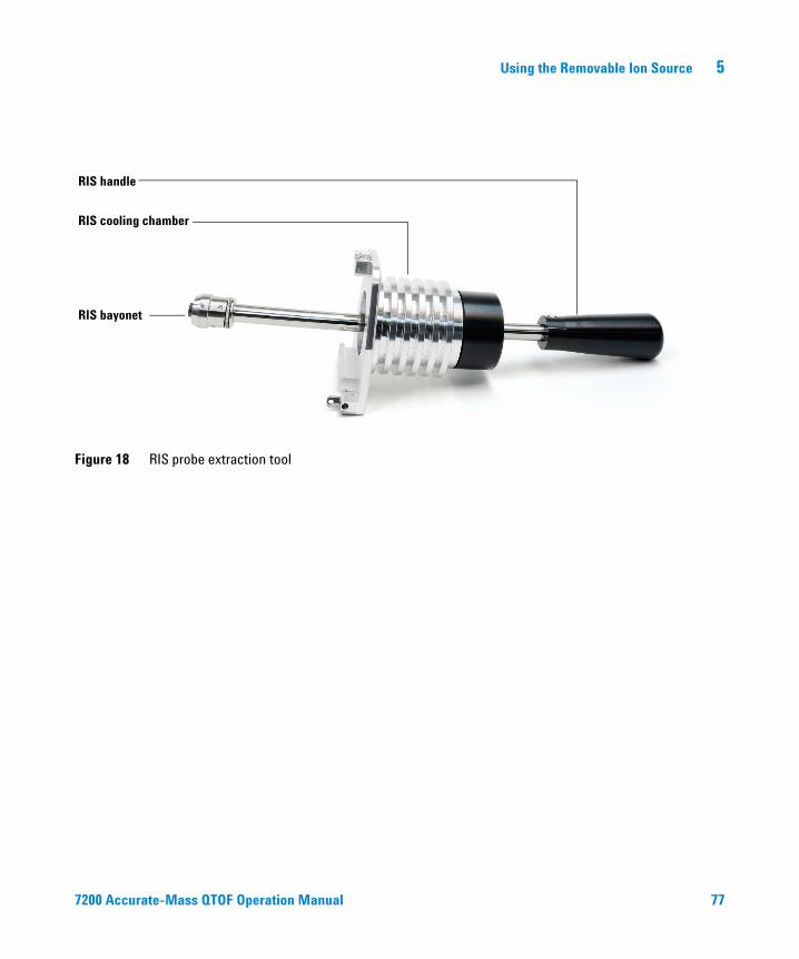
Using the Removable Ion Source 5
Figure 18 RIS probe extraction tool
RIS bayonet
RIS cooling chamber
RIS handle
7200 Accurate-Mass QTOF Operation Manual 77

5 Using the Removable Ion Source
To Change the Ion Source
78
The steps necessary for changing the ion source are provided here and also interactively in the MassHunter Workstation software. The process is mostly automated, with the exception of the use of the RIS probe extraction tool to remove and install the ion source. Purging the chamber, cooling the source, and pumping down are all performed with the use of the Workstation software.
Procedure
1 From MassHunter Data Acquisition software control view, click the MS Tune icon to display the GC/Q-TOF Tune dialog box.
2 Click the Removable Ion Source tab in the GC/Q-TOF Tune screen. (Figure 19)
Figure 19 GC/Q-TOF Tune dialog box
7200 Accurate-Mass QTOF Operation Manual

Using the Removable Ion Source 5
7200 Accurate-Mas
3 Click the Begin button to purge the instrument.
4 When prompted, remove the RIS chamber door and attach the RIS probe extraction tool. See “To Install the RIS Probe Extraction Tool” on page 80.
5 Click Next to purge the chamber and pump down.
6 When the system is ready for source removal, click Next to retract the transfer line and open the gate valve.
The RIS status area will note when the Gate Valve is Open and the Transfer Line is Full Out.
7 When prompted, remove the source. See “To Remove the Source from the Analyzer Chamber” on page 82.
8 Once the source is retracted fully into the chamber, click Next to close the gate valve and purge the cooling chamber. The purge takes approximately 10 minutes.
9 When prompted, open the cooling chamber and change the ion source. See “To Change the Ion Source on the RIS Probe Extraction Tool” on page 84.
10 After replacing the source and securing the cooling chamber door, click Next to purge and pump down.
11 When prompted that the system is ready for source installation, click Next to retract the transfer line and open the gate valve.
12 When prompted, install the ion source in the analyzer chamber. See “To Install the Ion Source in the Analyzer Chamber” on page 86.
13 Verify in the RIS Status that the ion source temperature readback shows a source temperature. This ensures that the source is fully inserted into its socket.
If the ion source is not fully installed, it may interfere with the gate valve as it closes.
CAUTIONDamage to the RIS, the valve, or the transfer line may occur.14 Click Next to close the gate valve and vent the RIS cooling chamber.
15 Remove the RIS probe extraction tool and replace the RIS chamber cover. See “To Remove the RIS Probe Extraction Tool from the Instrument” on page 87.
16 Click Next to pump down the chamber behind the RIS chamber cover.
17 When prompted, click Finish.
s QTOF Operation Manual 79

5 Using the Removable Ion Source
To Install the RIS Probe Extraction Tool
80
This procedure is part of an automated series of steps controlled by MassHunter. Do not attempt this procedure unless prompted by MassHunter to remove the RIS cover door.
Procedure
1 When prompted by MassHunter, remove the upper RIS cover (see “To Remove the Upper RIS Cover” on page 52).
2 Open the latch on the right side of the RIS cover door.
3 Swing the door open.
4 Lift the RIS cover door straight up to free it from the hinges, and remove.
Do not leave the instrument with the RIS cover off. If you remove the cover, you must
CAUTIONinstall the RIS probe as soon as possible to minimize contamination in the instrument.5 Holding the RIS probe extraction tool by the handle, position the RIS cooling chamber up against the instrument RIS chamber. Hold the handle perpendicular to the front of the instrument so that the outside edge of the cooling chamber is flush with the RIS chamber opening on the front instrument.
6 Line up the pins on the probe hinge with the slots on the instrument hinge.
7 Lower the pins into the hinge.
8 Close the cooling chamber door, and secure the door with the latch on the right side.
9 Return to step 5 in the “To Change the Ion Source” on page 78.
7200 Accurate-Mass QTOF Operation Manual

Using the Removable Ion Source 5
7200 Accurate-Mas
Figure 20 RIS cover door
Figure 21 RIS probe installed
s QTOF Operation Manual 81

5 Using the Removable Ion Source
To Remove the Source from the Analyzer Chamber
82
This procedure is part of an automated series of steps controlled by MassHunter. Do not attempt this procedure unless prompted by MassHunter. The RIS Status area on the GC/Q-TOF Tune tab must show the Gate Valve is Open and the Transfer Line is Full Out.
Procedure
1 Holding the RIS handle, turn the alignment guide, which is the white line on the RIS handle, to the 2 o’clock position from the top of the handle. This ensures that the RIS bayonet is aligned properly to attach to the source.
Figure 22 RIS Alignment guide
RIS Alignment guide (white line on RIS handle)
While the RIS handle is fully extended, do not bump or push it from the side. Doing so
CAUTIONwill break the seal and allow air into the cooling chamber.Do not try to guide the ion source in manually. Push the RIS handle gently and allow
CAUTIONthe RIS bayonet to slide on its own. The RIS bayonet will slide in straight if it is allowed to move naturally.7200 Accurate-Mass QTOF Operation Manual

Using the Removable Ion Source 5
7200 Accurate-Mas
2 Keeping the RIS handle in position, push the RIS handle gently and allow the RIS bayonet to extend into the analyzer chamber. Ensure the RIS handle extends fully, to ensure that the RIS bayonet seats in the holes on the ion source body properly.
3 When the ion source is properly seated, turn the RIS handle counter clockwise until the alignment guide is in the 12 o’clock position, to lock the ion source in place.
4 Pull the RIS handle toward you, keeping the alignment guide at the 12 o’clock position, to retract the ion source into the RIS cooling chamber.
5 Return to step 8 in the “To Change the Ion Source” on page 78.
s QTOF Operation Manual 83

5 Using the Removable Ion Source
To Change the Ion Source on the RIS Probe Extraction Tool
84
This procedure is part of an automated series of steps controlled by MassHunter. Do not attempt this procedure unless prompted by MassHunter. The RIS Status area on the GC/Q-TOF Tune tab must show the Gate Valve is Open and the RIS vacuum as 0.000 Torr.
CAUTION If not done correctly, source maintenance can introduce contaminants into the MS. Always wear clean rubber gloves when handling the source.
1 Undo the latch on the right edge of the RIS cooling chamber.
2 Swing open the RIS cooling chamber until the RIS handle is parallel with the front of the instrument.
3 Lock the RIS cooling chamber in the open position by opening it enough to engage the locking pin on the hinge.
The 7200 Q-TOF GC/MS operates at high temperatures. Ensure the source is cooled
WARNINGto a safe temperature before attempting to remove it from the RIS cooling chamber.4 Grasp the RIS handle with one hand, and the ion source body with the other hand.
5 While holding the ion source steady, turn the RIS handle counter clockwise so that the alignment guide is in the 2 o’clock position. This guides the pin on the RIS bayonet out of the track on the ion source body.
6 Gently pull the ion source free from the RIS bayonet and set aside.
7 Remove the new ion source from its storage container. The ion source remains connected to the lid. Twist the lid clockwise to separate the ion source from the lid.
8 Turn the RIS handle so that the alignment guide is in the 2 o’clock position.
9 Guide the pin on the RIS bayonet into the tracks on the end of the ion source body.
7200 Accurate-Mass QTOF Operation Manual

Using the Removable Ion Source 5
7200 Accurate-Mas
10 While holding the ion source securely, turn the RIS handle counter clockwise so that the alignment guide is in the 12 o’clock position, to lock the ion source securely on the bayonet.
11 Retract the RIS handle fully so that the ion source is located completely in the cooling chamber.
12 Raise the locking pin on the RIS cooling chamber hinge and swing it shut.
13 Secure the RIS cooling chamber to the instrument with the latch on the right side of the door.
14 Return to step 10 in the “To Change the Ion Source” on page 78.
s QTOF Operation Manual 85

5 Using the Removable Ion Source
To Install the Ion Source in the Analyzer Chamber
86
This procedure is part of an automated series of steps controlled by MassHunter. Do not attempt this procedure unless prompted by MassHunter. The RIS Status area on the GC/Q-TOF Tune tab must show the Gate Valve is Open and the Transfer Line is Full Out.
CAUTION Take care when walking past the front of the instrument when the RIS handle is fully extended, to avoid damage to the instrument. When closed, the RIS handle extends 48 cm (19 inches) out from the front of the instrument.
CAUTION Do not try to guide the ion source in manually. Push the RIS handle gently and allow the RIS bayonet to slide on its own. The RIS bayonet will slide in straight if it is allowed to move naturally.
Procedure
1 Ensure the alignment guide on the RIS handle is in the 12 o’clock position. Push the RIS handle gently towards the analyzer chamber and allow it to extend into the analyzer chamber. This will seat the ion source securely into its socket.
2 Once the RIS handle is fully extended, turn the RIS handle clockwise until the alignment guide is in the 2 o’clock position to release the ion source body from the RIS bayonet.
3 Pull the RIS handle toward you until it is fully retracted into the RIS cooling chamber.
4 Return to step 13 in the “To Change the Ion Source” on page 78.
7200 Accurate-Mass QTOF Operation Manual

Using the Removable Ion Source 5
To Remove the RIS Probe Extraction Tool from the Instrument
7200 Accurate-Mas
This procedure is part of an automated series of steps controlled by MassHunter. Do not attempt this procedure unless prompted by MassHunter. The RIS Status area on the GC/Q-TOF Tune tab must show the Gate Valve is Open and the RIS vacuum as 0.000 Torr.
WARNING The 7200 Q-TOF GC/MS operates at high temperatures. Ensure the RIS cooling chamber is at a safe temperature before attempting to remove it from the instrument.
1 Undo the latch on the right side of the RIS probe extraction tool and open the door.
2 Lift the RIS probe extraction tool up to release it from its hinges.
3 Replace the RIS probe extraction tool with the RIS chamber door.
4 Line up the hinge pins on the RIS chamber door with the slots on the instrument hinge, and lower the pins into the hinge.
5 Swing the RIS chamber door closed and secure the door with the latch on the right side.
6 Return to step 16 in the “To Change the Ion Source” on page 78.
s QTOF Operation Manual 87

88
5 Using the Removable Ion Source
7200 Accurate-Mass QTOF Operation Manual
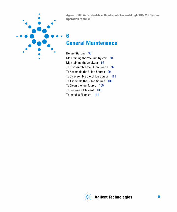
Agilent 7200 Accurate-Mass Quadrupole Time-of-Flight GC/MS System Operation Manual
6General Maintenance
Before Starting 90
Maintaining the Vacuum System 94
Maintaining the Analyzer 95
To Disassemble the EI Ion Source 97
To Assemble the EI Ion Source 99
To Disassemble the CI Ion Source 101
To Assemble the CI Ion Source 103
To Clean the Ion Source 105
To Remove a Filament 109
To Install a Filament 111
89Agilent Technologies
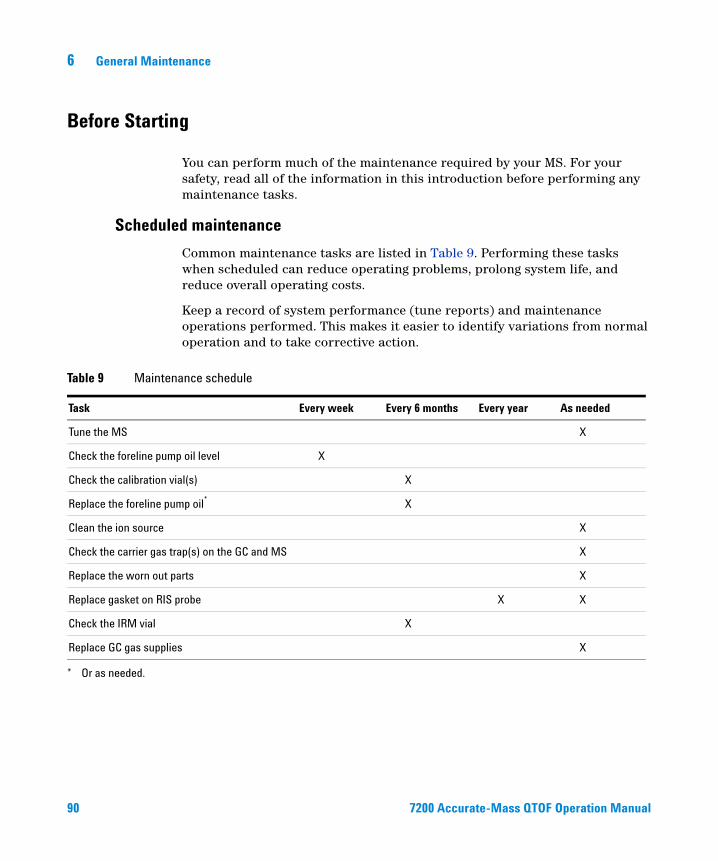
6 General Maintenance
Before Starting
90
You can perform much of the maintenance required by your MS. For your safety, read all of the information in this introduction before performing any maintenance tasks.
Scheduled maintenance
Common maintenance tasks are listed in Table 9. Performing these tasks when scheduled can reduce operating problems, prolong system life, and reduce overall operating costs.
Keep a record of system performance (tune reports) and maintenance operations performed. This makes it easier to identify variations from normal operation and to take corrective action.
nance schedule
Table 9 MainteTask Every week Every 6 months Every year As needed
Tune the MS X
Check the foreline pump oil level X
Check the calibration vial(s) X
Replace the foreline pump oil* X
Clean the ion source X
Check the carrier gas trap(s) on the GC and MS X
Replace the worn out parts X
Replace gasket on RIS probe X X
Check the IRM vial X
Replace GC gas supplies X
* Or as needed.
7200 Accurate-Mass QTOF Operation Manual

General Maintenance 6
Tools, spare parts, and supplies
7200 Accurate-Mas
Some of the required tools, spare parts, and supplies are included in the GC shipping kit, MS shipping kit, or MS tool kit. You must supply others yourself. Each maintenance procedure includes a list of the materials required for that procedure.
High voltage precautions
Whenever the MS is plugged in, even if the power switch is off, potentially dangerous voltage (200/240 VAC) exists on the wiring and fuses between where the power cord enters the instrument and the power switch.
When the power switch is on, potentially dangerous voltages exist on:• Electronic circuit boards• Toroidal transformer• Wires and cables between the boards• Wires and cables between the boards and the connectors on the back panel
of the MS• Some connectors on the back panel (for example, the foreline power
receptacle)
Normally, all of these parts are shielded by safety covers. As long as the safety covers are in place, it should be difficult to accidentally make contact with dangerous voltages.
Perform no maintenance with the MS turned on or plugged into its power source
WARNINGunless you are instructed to do so by one of the procedures in this chapter.Some procedures in this chapter require access to the inside of the MS while the power switch is on. Do not remove any of the electronics safety covers in any of these procedures. To reduce the risk of electric shock, follow the procedures carefully.
s QTOF Operation Manual 91

6 General Maintenance
Dangerous temperatures
92
Many parts in the MS operate at, or reach, temperatures high enough to cause serious burns. These parts include, but are not limited to:• GC/MS interface• Analyzer parts• Vacuum pumps
The foreline pump can cause burns if touched when operating.
WARNINGWARNING Never touch these parts while your MS is on. After the MS is turned off, give these parts enough time to cool before handling them.
WARNING The GC/MS interface heater is powered by a thermal zone on the GC. The interface heater can be on, and at a dangerously high temperature, even though the MS is off. The GC/MS interface is well insulated. Even after it is turned off, it cools very slowly.
The GC inlets and GC oven also operate at very high temperatures. Use the same caution around these parts. See the documentation supplied with your GC for more information.
Chemical residue
Only a small portion of your sample is ionized by the ion source. The majority of any sample passes through the ion source without being ionized. It is pumped away by the vacuum system. As a result, the exhaust from the foreline pump will contain traces of the carrier gas and your samples. Exhaust from the standard foreline pump also contains tiny droplets of foreline pump oil.
An oil mist filter is supplied with the standard foreline pump. This filter stops only pump oil droplets. It does not trap any other chemicals. If you are using toxic solvents or analyzing toxic chemicals, install a hose from the mist filter outlet to the outdoors or into a fume hood vented to the outdoors. Be sure to comply with your local air quality regulations.
7200 Accurate-Mass QTOF Operation Manual

General Maintenance 6
7200 Accurate-Mas
The oil trap supplied with the standard foreline pump stops only foreline pump oil. It
WARNINGdoes not trap or filter out toxic chemicals. If you are using toxic solvents or analyzing toxic chemicals, use a hose to vent to a safe location.The fluids in the foreline pump also collect traces of the samples being analyzed. All used pump fluid should be considered hazardous and handled accordingly. Dispose of used fluid as specified by your local regulations.
When replacing pump fluid, use appropriate chemical-resistant gloves and safety
Ion source cleaning
WARNINGglasses. Avoid all contact with the fluid.
The main effect of operating the MS in CI mode is the need for more frequent ion source cleaning. In CI operation, the ion source chamber is subject to more rapid contamination than in EI operation because of the higher source pressures required for CI.
Always perform any maintenance procedures using hazardous solvents under a
Ammonia
WARNINGfume hood. Be sure to operate the MS in a well-ventilated room.
Ammonia, used as a reagent gas, increases the need for foreline pump maintenance. Ammonia causes foreline pump oil to break down more quickly. Therefore, the oil in the standard foreline vacuum pump must be checked and replaced more frequently.
Always purge the MS with methane after using ammonia.
Be sure to install the ammonia so the tank is in an upright position. This will help prevent liquid ammonia from getting into the flow module.
s QTOF Operation Manual 93

6 General Maintenance
Maintaining the Vacuum System
Periodic maintenance
94
As listed in Table 9, some maintenance tasks for the vacuum system must be performed periodically. These include:
• Checking the foreline pump fluid color and level (every week)
• Checking the calibration vial(s) (every 6 months)
• Replacing the foreline pump oil and oil mist filter (every 6 months or as needed)
• Replacing the RIS probe seals (yearly or as needed)
Failure to perform these tasks as scheduled can result in decreased instrument performance. It can also result in damage to your instrument.
Other procedures
Tasks such as replacing an ion vacuum gauge should be performed only when needed by a certified Agilent service personnel. See the Agilent 7200 Accurate-Mass Q-TOF GC/MS Troubleshooting and Maintenance Manual and see the online help in the MassHunter WorkStation software for symptoms that indicate this type of maintenance is required.
More information is available
If you need more information about the locations or functions of vacuum system components, see the Agilent 7200 Accurate-Mass Q-TOF GC/MS Troubleshooting and Maintenance Manual.
Most of the procedures in this chapter are illustrated with video clips on the Agilent GC/MS Hardware User Information & Instrument Utilities and 7200 Q-TOF GC/MS User Information disks.
7200 Accurate-Mass QTOF Operation Manual

General Maintenance 6
Maintaining the Analyzer
Scheduling
7200 Accurate-Mas
None of the analyzer components requires periodic maintenance. Some tasks, however, must be performed when MS behavior indicates they are necessary. These tasks include:
• Cleaning the ion sources
• Replacing filaments
The Agilent 7200 Accurate-Mass Q-TOF GC/MS Troubleshooting and Maintenance Manual provides information about symptoms that indicate the need for analyzer maintenance. The troubleshooting material in the online help in the MassHunter Workstation software provides more extensive information.
Precautions
Keep components clean during analyzer maintenance. Never open the analyzer chamber. There are no customer serviceable parts accessible from this door.
If not done correctly, analyzer maintenance can introduce contaminants into the MS.
CAUTIONWARNING The analyzers operate at high temperatures. Do not touch any part until you are sure it is cool.
s QTOF Operation Manual 95
96
6 General Maintenance
Electrostatic discharge
The wires, contacts, and cables connected to the analyzer components can carry electrostatic discharges (ESDs) to the electronics boards to which they are connected. This is especially true of the mass filter (quadrupole) and collision cell contact wires which can conduct ESD to sensitive components on the quad driver board. ESD damage may not cause immediate failure but will gradually degrade performance and stability.
Electrostatic discharges to analyzer components are conducted to the quad driver
CAUTIONboard where they can damage sensitive components. Wear a grounded antistatic wrist strap and take other antistatic precautions when working on the analyzer.Analyzer parts that should not be disturbed
The mass filter (quadrupole) and the collision cell require no periodic maintenance. In general, the mass filter should never be disturbed. In the event of extreme contamination, it can be cleaned, but such cleaning should only be done by a trained Agilent Technologies service representative.
Incorrect handling or cleaning of the mass filter can damage it and have a serious,
More information is available
CAUTIONnegative effect on instrument performance. Never open the analyzer door.
If you need more information about the locations or functions of analyzer components, refer to the Agilent 7200 Accurate-Mass Q-TOF GC/MS Concepts Guide.
7200 Accurate-Mass QTOF Operation Manual

General Maintenance 6
To Disassemble the EI Ion Source
7200 Accurate-Mas
Materials needed
• Gloves, clean, lint-free
• Large (8650-0030)
• Small (8650-0029)
• Hex ball driver, 1.5 mm (8710-1570)
• Hex ball driver, 2.0 mm (8710-1804)
• Wrench, open-end, 10 mm (8710-2353)
• Nut driver, 5.5 mm (8710-1220)
• Tweezers (8710-2460)
Procedure
1 Remove the ion source. See “To Change the Ion Source” on page 78.
2 Remove the filaments. See “To Remove a Filament” on page 109.
3 Separate the ion focus and insulator assembly from the source body. (See Figure 23.)
4 Remove the two screws from the ion focus insulator and separate it from the ion focus lens.
5 Remove the extractor lens and its insulator from the source body.
6 Remove the two screws from the RIS bayonet mount on the bottom of the source body, and remove the RIS bayonet mount.
7 Remove the repeller assembly from the source body.
8 Disassemble the repeller assembly by separating the repeller, the repeller cap, ring heater and sensor assembly. (See Figure 23.)
9 Remove the clocking button from the repeller cap by removing the screw that holds it in place. (See Figure 23.)
s QTOF Operation Manual 97
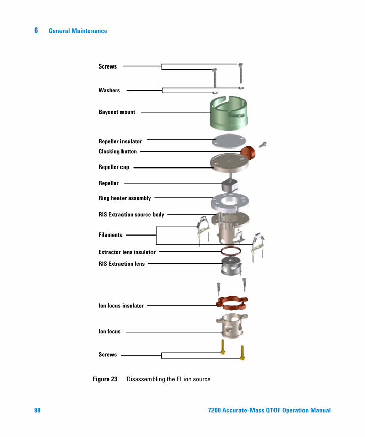
98
6 General Maintenance
Figure 23 Disassembling the EI ion source
Screws
Washers
Bayonet mount
Repeller insulator
Repeller cap
Repeller
Ring heater assembly
RIS Extraction source body
Filaments
Extractor lens insulator
RIS Extraction lens
Ion focus insulator
Ion focus
Screws
Clocking button
7200 Accurate-Mass QTOF Operation Manual

General Maintenance 6
To Assemble the EI Ion Source
7200 Accurate-Mas
Materials needed
• Gloves, clean, lint-free
• Large (8650-0030)
• Small (8650-0029)
• Hex ball driver, 1.5 mm (8710-1570)
• Hex ball driver, 2.0 mm (8710-1804)
• Wrench, open-end, 10 mm (8710-2353)
Procedure
Always wear clean gloves when working in the analyzer chamber to avoid
CAUTIONcontamination.1 Assemble the repeller assembly, by attaching the repeller to the repeller cap and connecting the clocking button with the screw.
2 Align the heater sensor with the source body.
3 Slide the repeller cap onto the heater sensor, and place the ceramic repeller insulator on top, aligning the screw holes.
4 Place the RIS bayonet mount on top of the ceramic repeller insulator, and attach with the washers and screws.
5 Attach the extractor lens insulator to the extractor lens, and slide them onto the other end of the source body (Figure 23).
6 Place the ion focus insulator on the ion focus lens and attach with the two screws.
7 Set the ion focus assembly on top of the extractor lens assembly on the source body.
8 Attach the filaments with the two screws.
While installing, do not overtighten the repeller nut or the ceramic repeller insulators
CAUTIONwill break when the source heats up. The nut should only be finger-tight.s QTOF Operation Manual 99

6 General Maintenance
100
Figure 24 Assembling the EI source
Screws
Washers
Bayonet mount
Repeller insulator
Repeller cap
Repeller
Ring heater assembly
RIS Extraction source body
Filaments
Extractor lens insulator
RIS Extraction lens
Ion focus insulator
Ion focus
Screws
Clocking button
7200 Accurate-Mass QTOF Operation Manual

General Maintenance 6
To Disassemble the CI Ion Source
7200 Accurate-Mas
Materials needed
• Gloves, clean, lint-free
• Large (8650-0030)
• Small (8650-0029)
• Hex ball driver, 1.5 mm (8710-1570)
• Hex ball driver, 2.0 mm (8710-1804)
• Wrench, open-end, 10 mm (8710-2353)
• Nut driver, 5.5 mm (8710-1220)
• Tweezers (8710-2460)
Procedure
1 Remove the CI ion source. See “To Change the Ion Source” on page 78.
2 Remove the filament. See “To Remove a Filament” on page 109.
3 Remove the ion focus lens and insulator. (See Figure 25.)
4 Remove the two screws from the ion focus lens insulator and separate it from the ion focus lens.
5 Remove the two screws from the RIS bayonet mount and remove the repeller assembly.
6 Disassemble the repeller assembly by removing the ceramic insulator and heater assembly from the repeller. (See Figure 25.)
7 Take the repeller off the source body.
s QTOF Operation Manual 101

102
6 General Maintenance
Figure 25 Disassembling the CI ion source
Bayonet mount
Repeller
Ring heater / Sensor assembly
RIS CI source body
Filament
Ion focus insulator
Ion focus lens
Clocking button
7200 Accurate-Mass QTOF Operation Manual

General Maintenance 6
To Assemble the CI Ion Source
7200 Accurate-Mas
Materials needed
• Gloves, clean, lint-free
• Large (8650-0030)
• Small (8650-0029)
• Hex ball driver, 1.5 mm (8710-1570)
• Hex ball driver, 2.0 mm (8710-1804)
• Wrench, open-end, 10 mm (8710-2353)
Procedure
CAUTION Always wear clean gloves when working in the analyzer chamber to avoid contamination.
1 Place the ceramic heater assembly on top of the repeller, aligning the grooves on the repeller with the slot on the heater assembly. (Figure 26).
2 Place the repeller on the source body. (Figure 26).
3 Place the assembled parts into the RIS bayonet mount, heater side first.
4 Align the interface socket in the source body with the alignment groove in the RIS bayonet mount. Attach with the two screws.
5 Place the ion focus and ion focus insulator together and attach with the two screws.
CAUTION While installing, do not overtighten the repeller nut or the ceramic repeller insulator will break when the source heats up. The nut should only be finger-tight.
6 Set the filament in place.
7 Place the ion focus assembly on the source body, with the insulator against the source body. Ensure all pins are facing in the same direction.
8 Attach with the two screws.
s QTOF Operation Manual 103

104
6 General Maintenance
Figure 26 Assembling the CI ion source
Bayonet mount
Repeller
Ring heater / Sensor assembly
RIS CI source body
Filament
Ion focus insulator
Ion focus lens
Clocking button
7200 Accurate-Mass QTOF Operation Manual

General Maintenance 6
To Clean the Ion Source
7200 Accurate-Mas
Frequency of cleaning
Because the CI ion source operates at much higher pressures than the EI ion source, it will probably require more frequent cleaning than the EI ion source. Cleaning of the source is not a scheduled maintenance procedure. The source should be cleaned whenever there are performance anomalies that are associated with a dirty ion source. See the 7200 Q-TOF GC/MS Troubleshooting and Maintenance Manual for symptoms that indicate a dirty ion source.
Visual appearance is not an accurate guide to cleanliness of the CI ion source. The CI ion source can show little or no discoloration yet still need cleaning. Let analytical performance be your guide.
Materials needed
• Abrasive paper (5061-5896)
• Alumina abrasive powder (8660-0791)
• Aluminum foil, clean
• Cloths, clean (05980-60051)
• Cotton swabs (5080-5400)
• Glass beakers, 500 mL
• Gloves, clean, lint-free• Large (8650-0030)• Small (8650-0029)
• Solvents• Acetone, reagent grade• Methanol, reagent grade• Methylene chloride, reagent grade
• Ultrasonic bath
s QTOF Operation Manual 105

106
6 General Maintenance
Preparation
1 Disassemble the ion source. See “To Disassemble the EI Ion Source” on page 97 or “To Disassemble the CI Ion Source” on page 101.
2 Collect the following parts to be cleaned if you are cleaning a high sensitivity extractor EI ion source: (Figure 27)
• Repeller• Source body• Extractor lens• Ion focus lens
Collect the following parts to be cleaned if you are cleaning a CI source:• Repeller• Source body• Ion focus lens
These are the parts that contact the sample or ion beam. The other parts normally should not require cleaning.
If insulators are dirty, clean them with a cotton swab dampened with reagent-grade
CAUTIONmethanol. If that does not clean the insulators, replace them. Do not abrasively or ultrasonically clean the insulators.Cleaning the CI ion source is very similar to cleaning the EI ion source, with the following exceptions:• The CI ion source may not look dirty but deposits left by chemical
ionization are very difficult to remove. Clean the CI ion source thoroughly.• Use a round wooden toothpick to gently clean out the electron entrance
hole in the source body.• Do not use halogenated solvents. Use hexane for the final rinse.
Do not use halogenated solvents to clean the CI ion source.
CAUTION7200 Accurate-Mass QTOF Operation Manual

General Maintenance 6
7200 Accurate-Mas
Figure 27 Extractor EI Source parts to be cleaned
RepellerExtractor lens Source bodyIon focus lens
Figure 28 CI Source parts to be cleaned
RepellerSource bodyIon focus lens
The filaments, source heater assembly, and insulators cannot be cleaned
CAUTIONultrasonically. Replace these components if major contamination occurs.3 If the contamination is serious, such as an oil backflow into the analyzer, seriously consider replacing the contaminated parts.
s QTOF Operation Manual 107

108
6 General Maintenance
4 Abrasively clean the surfaces that contact the sample or ion beam.
Use an abrasive slurry of alumina powder and reagent-grade methanol on a cotton swab. Use enough force to remove all discolorations. Polishing the parts is not necessary; small scratches will not harm performance. Also abrasively clean the discolorations where electrons from the filaments enter the source body.
5 Rinse away all abrasive residue with reagent-grade methanol.
Ensure all abrasive residue is rinsed away before ultrasonic cleaning. If the methanol becomes cloudy or contains visible particles, rinse again.
6 Separate the parts that were abrasively cleaned from the parts that were not abrasively cleaned.
Always wear clean gloves to prevent contamination when working in the analyzer
CAUTIONchamber.7 Ultrasonically clean the parts (each group separately) for 15 minutes in each of the following solvents:
• Methylene chloride (reagent-grade)
• Acetone (reagent-grade)
• Methanol (reagent-grade)
All of these solvents are hazardous. Work in a fume hood and take all appropriate
WARNINGprecautions.8 Place the parts in a clean beaker. Loosely cover the beaker with clean aluminum foil (dull side down).
9 Dry the cleaned parts in an oven at 100 °C for 5–6 minutes.
7200 Accurate-Mass QTOF Operation Manual

General Maintenance 6
To Remove a Filament
7200 Accurate-Mas
Materials needed
• Gloves, clean, lint-free
• Large (8650-0030)
• Small (8650-0029)
• Hex ball driver, 1.5 mm (8710-1570)
• Tweezers (8710-2460)
Procedure
CAUTION Always wear clean gloves to prevent contamination when working in the analyzer chamber.
1 Remove the ion source. See “To Change the Ion Source” on page 78.
2 Remove the screw holding the filament to the ion source body. (See Figure 29.)
3 Slide the filament off the ion source assembly. (See Figure 29.)
WARNING The analyzer, GC/MS interface, and other components in the analyzer chamber operate at very high temperatures. Do not touch any part until you are sure it is cool.
s QTOF Operation Manual 109

6 General Maintenance
Figure 29 Changing the filament
EI Source
Filaments
CI Source
Filament
110 7200 Accurate-Mass QTOF Operation Manual

General Maintenance 6
To Install a Filament
7200 Accurate-Mas
Materials needed
• Filament assembly, EI (G7005-60061)
• Filament assembly, CI (G7005-60072)
• Gloves, clean, lint-free
• Large (8650-0030)
• Small (8650-0029)
• Tweezers (8710-2460)
Procedure
1 Remove the old filament. (See “To Remove a Filament” on page 109.)
2 Place the new filament into its position on the ion source body. (See Figure 29.)
3 Secure the filament to the ion source body with the screw.
4 After installing the filament, verify that it is not grounded to source body.
5 Reinstall the ion source. (See “To Change the Ion Source” on page 78.)
6 Autotune the MS.
Do not overtighten the thumbscrew; it can cause air leaks or prevent successful
CAUTIONpumpdown. Do not use a screwdriver to tighten the thumbscrew.s QTOF Operation Manual 111

112
6 General Maintenance
7200 Accurate-Mass QTOF Operation Manual


Agilent Technologies
Printed in USA, August 2014
*G3850-90008*G3850-90008
© Agilent Technologies, Inc.