Embed Size (px)
Citation preview

Complete, intelligent and safe
Drive System Rexroth IndraDrive
ServicePneumaticsLinear Motion andAssembly TechnologiesHydraulics
Electric Drivesand Controls


ContentsDrive expertise
System overview
Selection guide
Power units IndraDrive C and M
Control units IndraDrive C and M
Multi-protocol-capable compact drive system IndraDrive Cs
Distributed drive system IndraDrive Mi
Firmware
Motion logic
Safety technology
Engineering and operating
Motors and gearboxes
Auxiliary components
Glossary
Formulas
Additional information
Discover the unlimited possibilities of Control City! The control technology capital integrates all control and drive components to provide optimum auto- mation solutions – and therefore maxi-mum future safety.
014
028
0310
0412
0534
0648
0752
0860
0962
1064
1168
1272
13106
14130
15132
134
16

4 01 Drive expertise
Rexroth IndraDrive and Rexroth IndraDyncause a stir in the drive marketSolve your automation challenges easily, cost-efficiently and safely with systems from Control City – the control technology capital. IndraDrive sets new standards in drive technology with a combina-tion of three product advantages:
• Scalable in power and func- tionality
• Consistent in technology, engineering and operation
• Open in communication
This means that IndraDrive has numerous application advantages to offer, e.g.:• Easy realization of frequency
converter to high-end servo applications by using a common platform for open and closed loop
• Scalable range of performance and functionality thanks to the free combination of control and power components
• Wide performance range from 100 W to 630 kW
• Internationally standardized interfaces from analog input to Multi-Ethernet interface
• Integrated safety technology compliant with EN 13849-1 Cat. 3 PL d and EN 62061 SIL 2 for Safe Stop and Safe Motion
• Intelligent motion logic with PLC according to IEC 61131-3
• Uniform operating philosophy • Consistent engineering tool• Direct power connection• Common DC bus for exchanging
energy in multiple-axis mode• Energy-saving power recovery• Motors with the highest level of
efficiency

Your benefit
Driv
e ex
pert
ise
015
IndraDrive has the powerto convinceNo matter what demands you make on your drive –IndraDrive offers an impressive array of key benefits:
Integrated l hardware platformScalable l functionalityUnique l safety concept
Safety on BoardSafety technology certified to EN 13849-1 Cat. 3 PL d and EN 62061 SIL 2, protects machine operators while the drives are in motion. In contrast to conven-tional safety designs, there is no longer any need for motor contact-ors, additional speed monitors or frequent power shutdown using the line contactor.
Integrated motion logic withIEC 61131-3 compliant PLCMotion logic with IEC 61131-3 compliant PLC can be integrated as an optional feature that con-sistently applies open standards. This makes it easier to bring in customer know-how and saves on higher-level control systems and personnel training courses.
Integrated technology functionsThe technology functions can be configured on the basis of motion logic to perform a wide and diverse range of process-oriented tasks. This does not require any pro-gramming knowledge whatsoever on the user’s part.
Open interfaces Internationally recognized inter-faces are available for communi-cating with higher-level machine control systems: SERCOS 2, SERCOS III, Multi-Ethernet (SERCOS III, PROFINET IO, EtherNet/IP, EtherCat), PROFIBUS, PROFINET IO,
CANopen, DeviceNet, analog and parallel.
A single software for all tasksThe engineering framework, IndraWorks, carries you through all the steps involved in project planning, programming, param-eterization, operation and diag-nostics.
A unique platformIn the interests of meeting your individual requirements, we have developed two versions of IndraDrive: • IndraDrive C –
Compact converters • IndraDrive M –
Modular invertersParticularly economic drive solu- tions can be derived from the common control units and the combination of different versions.
A complete range of motorsThe newly developed generation of IndraDyn motors meets all the requirements of modern factory automation through its diversity of design and unique performance:• Synchronous and asynchronous
servo motors which are more compact and more powerful
• Servo motors designed for poten-tially explosive areas – conform-ing to ATEX and UL/CSA
• Synchronous and asynchronous motors for high-speed applica-tions such as motor spindles
Automation
Printing and convertingmachines
Conveying and storagesystems
Glass processing machines
Handling and assemblysystems
Woodworking machines
Plastics processing machines
Food processing andpackaging machines
Textile machines
Metal forming
Machine tools
Semiconductor technology

6 01 Drive expertise
Rexroth IndraDrive –complete, intelligent and safe

Driv
e ex
pert
ise
017
IndraDrive stands for innovationall along the line. Therefore,choosing the new drive generationfrom Rexroth means that yourevery wish will be fulfilled.
Main features of the IndraDrive: • Compact converters and modular
inverters on one platform • Ethernet-based communications
hardware with multi-protocol support
• Ultra-compact drive unit con-sisting of control unit and servo motor
• Integrated motion logic with IEC-compliant PLC
• Drive-integrated safety technology
• Intelligent technology functions• Integrated engineering frame-
work for project planning, programming, operation and diagnostics
• Complete range of synchronous and asynchronous motors

8 02 System overview
Rexroth IndraDrive –the complete system
Control units
Complete solutions for standard applications
BASIC OPEN LOOPCSB...FCPage 38
BASIC ANALOGCSB...ANPage 39
BASIC PROFIBUSCSB...PBPage 40
BASIC SERCOSCSB...SEPage 41
Individually configurable for standard and high-end applications
BASIC UNIVERSALCSB (single-axis control unit)Page 42
BASIC UNIVERSALCDB (double-axis control unit)Page 43
ADVANCEDCSHPage 44
Power units Control units
Compact drives featuring Ethernet-based communicationsHCS01 converter – ECONOMY and BASIC UNIVERSAL versionsPages 48 – 51
ConvertersHCS02Pages 16/17
HCS03Pages 18/19
HCS04Pages 22/23
Inverters Converters and inverters can be combined
InvertersHMS (single-axis unit)Pages 24/25
HMD (double-axis unit)Pages 26/27
Power supplies and inverters can be combined
Power supply unitsHMV Pages 28 – 29
Motor-integrated drivesKSM, KMS, KCUPages 52 – 59
For
conv
erte
rs a
nd in
vert
ers
Motors and gearboxes
Synchronous servo motorsIndraDyn S, MSK, MKE, MSMPages 74 – 81
Asynchronous servo motorsIndraDyn A, MAD, MAFPages 82 – 89
Synchronous linear motorsIndraDyn L, MLP/MLSPages 90/91
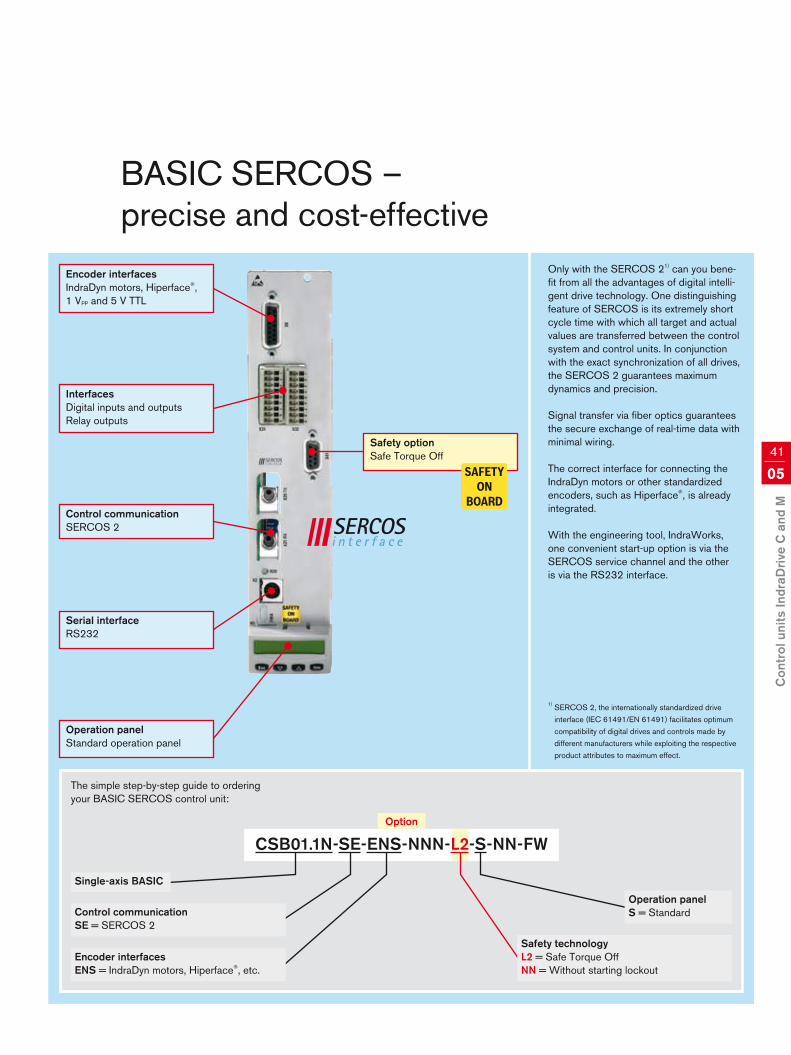
Synchronous torque motorsIndraDyn T, MST/MRTPages 92/93
Synchronoushigh-speed motorsIndraDyn H, MSS/MRSPages 94/95
Asynchronousframeless (kit) motors1MBPages 96/97
Gearboxes for servo motorsGTE, GTMPages 98 – 101
Standard motors,geared motorsPages 102 – 105
AC
DC
DC
AC
AC
AC

Your benefit
Sys
tem
ove
rvie
w
029
Seamlessly coordinatedIntegrated l systemScalable l powerFlexible l function blocksOpen l communications standardsFuture-proof l
Firmware
Basic package
The basic package contains all the functions for standard applications.
Extension packages
Frictional torque compensation and com-pensation for backlash on reversal, axis and encoder error correction, touch probe, etc.
Electronic gears, electronic cam plate, etc.
Spindle positioning, gear change, etc.
Motion logic conforming to IEC 61131-3
Productivity Agent (predictive maintenance),function blocks, demand processing, specialcam groups, extended drive function,PLCopen library, etc.
Pages 60/61
OPEN LOOP / CLOSED LOOP
SERVO
SYNCHRONISATION
MAIN SPINDLE
IndraMotion MLD
Technology packages based on IndraMotion MLD
Auxiliary components
Mains filtersHNF, HNS, NFDPage 108
Mains filters, mains chokeHNKPage 109
Mains chokesHNLPages 110/111DC chokesHLLPage 112
Motor filtersHMFPage 113
Brake resistorsHLRPages 115 – 117
Brake chopperHLTPage 114 Brake unitsHLBPage 116
Capacity moduleHLCPage 117
Blower unitHABPage 118
Engineering and operation
Operation panelsVCP, VCH, VEPPage 45
Software modulePFMPage 45
IndraWorksEngineering software framework for start-up, programming, etc.Pages 68/69
Cables
Power cablesRKLPages 126/127
Encoder cablesRKGPages 126/127
Fiber optic cables,bus connectors, etc.
Hybrid cable, terminal connectorRKHPage 59

10 03 Selection guide
Five steps to your drive solution

Sel
ectio
n gu
ide
0311
Help
Drive sizingprogramIndraSizePages 70/71
Auxiliary componentsPages 106 – 127
Engineering frameworkPages 68/69
FirmwarePages 60/61
Control unitsPages 34 – 47
Power unitsPages 12 – 33
MotorsPages 72 – 105
Example
I Servo drive for a handling axis• RMS torque 4.5 Nm• Maximum torque 8 Nm• Speed 2,500 min-1
• Interface PROFIBUS• Simple servo functionality
I Mains filter NFD03.1-480-016I Power cable RKL4302/005,0I Encoder cable RKG4200/005,0I Basic accessories HAS01.1-065-NNN-CNI Shield connection HAS02.1-002-NNN-NNI Software SWA-IWORKS-D**-xxVRS-D0-DVD**-COPY
I Basic CLOSED LOOP packageFWA-INDRV*-MPB-xxVRS-D5-1-NNN-NN• No extension packages
I Control unit BASIC PROFIBUS CSB01.1N-PB-ENS-NNN-NN-S-NN-FW• Standard performance • PROFIBUS• IndraDyn standard encoder• Standard operator panel• No additional options
I IndraDrive C with IndraDyn SHCS02.1E-W0028-A-03-NNNNMSK050C-0300-NN-S1-UG0-NNNN• Standstill torque 5 Nm• Maximum torque 15 Nm• Maximum speed 4,700 min-1
Step
Determine your drive requirements• Torque, speed, power …• Performance (control quality …)• Interfaces, functions • Single-axis or multi-axis drive
Select the accessories• Mains filters and mains chokes• Brake resistors, brake units• Capacity modules• Cables• Software
Define the firmware function• Basic OPEN LOOP or
CLOSED LOOP package• Extension packages • Motion logic• Technology functions
Identify the control unit performance and interfaces• Higher-level control system• Encoder • Inputs and outputs• Safety technology
Select the power unit/motor combination
1
5
4
3
2

12 04 Power units IndraDrive C and M
Rexroth IndraDrive –power units

Your benefit
Pow
er u
nits
Indr
aDriv
e C
and
M
0413
IndraDrive C – compact converters
• Power range from 1.5 kW to 630 kW with maximum current from 12 A to 1,535 A
• High overload capacity• Compact design for single-axis applications• Can be connected to inverters for cost-effective solutions• Direct mains connection from 200 V to 500 V
IndraDrive M – modular inverters
• Single-axis inverter with maximum current from 20 A to 350 A• Double-axis inverter with maximum current from 12 A to 36 A• Space-saving design for multi-axis applications• Can be powered via power supply unit or converter• Energy exchange via common DC bus• Can be connected to a converter for cost-effective solutions
IndraDrive M – modular power supplies
• Power range from 15 kW to 120 kW • Direct mains connection from 400 V to 480 V• Energy-saving line regeneration• Integrated mains contactor • Integrated brake resistor
Converters and inverters can be combined
Power supplies and inverters can be combined
Customized for the desired num- ber of axes and performance level
Wide l power range – for all applications Converters l and inverters can be combined – ideal for small axis groups Power l supplies and inverters can be combined – ideal for large axis groups
AC
DC
DC
AC
AC
AC

14 04 Power units IndraDrive C and M
Single-axis solution with a converterThe IndraDrive C series of converters integrate inverter and power supply in one unit. The compact construction contains additional mains con- nection components, making it particularly suitable for single-axis applications.
Multi-axis solution withconverters and invertersA combination of IndraDrive C converters and modular Indra- Drive M inverters is a particularly cost-effective solution for small axis groups.
The converter for the first axis supplies the inverters of the other axes at the same time. In this case, a converter with sufficient power reserve must be selected in order to be able to supply the smaller inverters as well.
Multi-axis solution with power suppliesand invertersMulti-axis applications are the domain of the modular system IndraDrive M. Power supplies provide the necessary DC bus voltage for the inverters. Compact single-axis or double-axis inverters and power supplies with integrated mains connection components enable compact solutions for large axis groups.
Maximum energy efficiency can be achieved with power supplies that are capable of mains regeneration. Beside the power recovery en- countered in regenerative operation of the drives, these devices also feature sinusoidal line currents, an overall power factor of 0.99 and a closed- loop DC bus.
3 AC 400 V ... 480 V
3 AC 400 V ... 500 V
IndraDrive –the clever combination of power units
3 AC 200 V ... 500 V
Control voltage
Module bus
DC bus
MMM
MM M
M
MM MM

Pow
er u
nits
Indr
aDriv
e C
and
M
0415
IndraDrive C IndraDrive M
Power units Converter Inverter Power supply units infeed
Power supply units regenerative
HCS02 HCS03 HCS04 HMS01/HMS02HMD01
HMV01.1E HMV01.1RHMV02.1R
Mains voltage V
1 AC 200 … 250 V
3 AC 200 … 500 V
(±10 %)
3 AC 400 … 500 V
(+10 %/–15 %)
3 AC 380 … 480 V
(+10 %/–15 %)– 3 AC 400 … 480 V (+10 %/–15 %)
Supply frequency Hz 48 … 62 – 48 … 62
DC bus continuous power kW 2.1 … 14 13 … 85 – – 18 … 120
Continuous mechanical power1) kW 1.5 … 11 11 … 75 110 … 630 1.5 … 75 –
Overload capacity 2.5x 1.5 … 2x 1.2 … 1.65x 1.5 … 2.5x 1.5x 1.5 … 2.5x
Switching frequency/
max. output frequency
kHz/
Hz
4/400 4/400 –
8/800 8/800 –
12/1,200 – 12/1,2002) –
16/1,600 – 16/1,6002) –
Output voltage V
0 … 335 (at DC bus voltage DC 475 V)
0 … 400 (at DC bus voltage DC 570 V)
0 … 530 (at DC bus voltage DC 750 V)
–
Suitable for cabinet depth mm 300 400 600 HMx01: 400/HMx02: 300
Mains contactor external – internal3)
Brake chopper internal internal or external – internal3)
Brake resistor internal
(optional external)external – internal3)
Converter/inverter combination yes yes yes yes –
Control voltage DC 24 Vexternal
(optional internal)internal or external external
Protection category IP20
Installation height m 1,000 over NN, with derating to 4,0004)
Ambient temperature °C 0 ... +40, with derating to +55
Relative air humidity % 5 … 95 (as per EN 61800-5-1), no dewing
Degree of contamination 2 (as per EN 61800-5-1)
Cooling system Air cooling
CE-mark Complies with the low voltage directive 73/23/EEC and the EMC directive 89/336/EEC
Certification EN 6800-5-1, EN 61800-03, UL 508c, C22.2 No. 14-05
EMC C3 (as EN 61800-3)All data for nominal rating at 3 AC 400 V mains voltage and 4 kHz switching frequency1) applies to S1 mode on 4-pole standard motors 3 AC 400 V/50 Hz at 4 kHz switching frequency and a rotary frequency > 4 Hz2) HMD01 and HMS02.1N-W0028 up to 8 kHz/800 Hz only3) not applicable for HMV01.1R-W01204) HCS04 up to 3,000 m

H
D W
16 04 Power units IndraDrive C and M
IndraDrive C –compact converters HCS02
Converters
Modelswith integrated control voltage supplywith integrated temperature-dependent fan controlno additional options
HCS02.1E-W0012-A-03-NNNV-A-03-LNNN-A-03-NNNN
HCS02.1E-W0028-A-03-NNNV-A-03-LNNN-A-03-NNNN
HCS02.1E-W0054-A-03-NNNV-A-03-LNNN-A-03-NNNN
HCS02.1E-W0070-A-03-NNNV-A-03-LNNN-A-03-NNNN
Performance data
Continuous current1) A 4.5 11.3 20.6 28.3
Maximum current A 11.5 28.3 54 70.8
DC bus continuous power without/with choke kW 2.1/2.1 5.1/5.1 7/10 9/14
Maximum output without/with choke kW 5/5 8/10 12/16 14/19
Mains voltage V 3 AC 200 ... 500, 1 AC 200 ... 250 (±10 %)
Continuous input mains current A 6 13 19 30
Dependence of output on mains voltageat ULN < 400 V: 1 % power reduction per 4 V
at ULN > 400 V: 1 % power gain per 5 V
DC bus terminal2) –
DC bus capacity µF 135 270 405 675Brake resistor
Brake resistor internal internal internal/external internal/externalMaximum braking energy consumption kWs 1 5 9 13Permanent braking power kW 0.05 0.15 0.35/3.8 0.5/5.5Maximum braking power kW 4 10 18 25Control voltage data
Control voltage, internal V DC 24 (not for supply of motor holding brake)Control voltage, external V DC 24 ±20 % (DC 24 ±5 % when supplying motor holding brake)Power consumption without control unit and motor brake W 12 14 23 23Continuous current without control unit and motor brake A 0.5 0.6 1 1Mechanical data
Width W mm 65 65 105 105Height H mm 290 352Depth D mm 252Mass kg 2.9 3.8 6.7 6.8All data for nominal rating at 3 AC 400 V mains voltage and 4 kHz switching frequency1) in case of output frequency less than 4 Hz the output current will be reduced2) for the connection of additional units, such as HMS, HCS, HLB, HLC

DC bus terminal
Control voltage
L–
L+
0 V
24 V
3~
3~
External brakeresistor HLR
Main contactor
CapacitymoduleHLC
BrakeunitHLB
Inte
rnal
pow
er
supp
ly
X5 Motor connection
X9
X6
Main choke HNL
Main filter HNF, NFD
U2 V2 W2
U1 V1 W1
L1.1 L2.1 L3.1
L1 L2 L3
X3 Mains connection
Mot
Tem
p +
Mot
Tem
p –
Bra
ke +
24
VB
rake
0 V
Module bus X1
Con
trol
uni
t
L1 L2 L3
A1 A2 A3
Module bus X1
L+
0 V
24 V
L–
1 AC 200 ... 250 V3 AC 200 ... 500 V
When mains filters HNF and NFD are used,the maximum input voltage is 3 AC 480 V.
PEW2V2U2Motor filter HMF
U1 V1 W1
3~M
Optional auxiliary component
Connection X9 not required with HCS02.1E-W0012and -W0028. No DC bus terminal with HCS02.1E-W0012
Pow
er u
nits
Indr
aDriv
e C
and
M
0417
HCS02

H
D W
18 04 Power units IndraDrive C and M
IndraDrive C –compact converters HCS03
Converters
Models
with integrated control voltage supplywith integrated control voltage supply and brake chopperwith integrated control voltage supply, brake chopper andfan control
HCS03.1E-W0070
-A-05-NNNV-A-05-NNBV-A-05-LNBV
HCS03.1E-W0100
-A-05-NNNV-A-05-NNBV-A-05-LNBV
HCS03.1E-W0150
-A-05-NNNV-A-05-NNBV-A-05-LNBV
HCS03.1E-W0210
-A-05-NNNV-A-05-NNBV-A-05-LNBV
Performance data
Continuous current1) A 45 73 95 145
Maximum current A 70 100 150 210
DC bus continuous power without/with choke kW 13/25 24/42 34/56 42/85
Maximum output without/with choke kW 20/40 33/59 54/89 68/124
Mains voltage V 3 AC 400 ... 500 (+10 %/–15 %)
Continuous input mains current A 50 80 106 146
Dependence of output on mains voltage at ULN < 400 V: 1 % power reduction per 4 V decrease in voltage
DC bus terminal2)
DC bus capacity µF 940 1,440 1,880 4,700
Brake chopper
Permanent braking power kW 13.2 18.9 25.2 42.6
Maximum braking power kW 42 63 97 137
Control voltage data
Control voltage, internal V DC 24 (not for supply of motor holding brake)
Control voltage, external V DC 24 ±20 % (DC 24 ±5 % when supplying motor holding brake)
Power consumption without control unit and motor brake W 22.5 25 25 30
Continuous current without control unit and motor brake A 0.9 1 1 1.3
Mechanical data
Width W mm 125 225 225 350
Height H mm 440
Depth D mm 309
Mass kg 13 20 20 38All data for nominal rating at 3 AC 400 V mains voltage and 4 kHz switching frequency1) in case of output frequency less than 4 Hz the output current will be reduced 2) for the connection of additional units, such as HMS, HCS, HLB, HLC

Mot
Tem
p +
Mot
Tem
p –
Bra
ke +
24
VB
rake
0 V
Control voltage
DC bus terminal
PE
Brake chopper
PEW2V2U2
Mains filter HNKwith integrated
mains choke
Mains contactor
X5 Motor connection
Motor filter HMF
U1 V1 W1
X1
3~
3~
External brakeresistor HLR
Internal power supply
3~M
A1 A2 A3X6
L–
L+
0 V
24 V
L1 L2 L3
L1.1 L2.1 L3.1
L1 L2 L3
Optional auxiliary component
When HNF mains filters are used, the maximum input voltage is 3 AC 480 V.Mains choke always required with HCS03.1E-W0210
Con
trol
uni
t
Module bus
X 9
Module busX1
L–
L+
0 V
24 V
3 AC 400 ... 500 V
X3 Mains connection
Mains choke HNL
Mains filter HNF
U2 V2 W2
U1 V1 W1
L1.1 L2.1 L3.1
L1 L2 L3
alternative
Mains contactor
CapacitymoduleHLC
BrakeunitHLB
Pow
er u
nits
Indr
aDriv
e C
and
M
0419
HCS03

20 04 Power units IndraDrive C and M
IndraDrive C – powerful converters HCS04
Converters
Models HCS04.2E-W0350-N-04-
NNBN
HCS04.2E-W0420-N-04-
NNBN
HCS04.2E-W0520-N-04-
NNBN
HCS04.2E-W0640-N-04-
NNNN
HCS04.2E-W0790-N-04-
NNNN
HCS04.2E-W1010-N-04-
NNNN
HCS04.2E-W1240-N-04-
NNNN
HCS04.2E-W1540-N-04-
NNNN
Power data with high continuous load1)/high overload2)
Typical motor ratingkW 132/110 160/132 200/160 250/200 315/250 400/315 500/400 630/500
hp 200/150 250/200 300/250 400/300 500/400 600/400 700/600 900/700
Continuous current A 259/215 300/257 366/313 459/387 586/477 720/614 894/749 1,126/930
Maximum current 60 s A 311/323 360/386 439/470 551/581 703/716 864/921 1,073/1,124 1,351/1,395
Maximum current 2 s A 350/355 405/424 494/516 620/639 791/787 972/1,013 1,207/1,236 1,520/1,535
Power supply continuous current3) A 226/194 271/229 338/277 418/340 527/424 660/529 834/675 1,037/834
Power supply voltage V 3 AC 380 ... 480 (+10 %/–15 %)
DC bus terminal
DC bus capacity mF 7.8 7.8 10.4 10.8 15.6 16.2 23.4 31.2
Brake chopper
Brake chopper internal internal internal internal external external external external
Permanent braking power kW 85 100 120 200 200 400 400 400
Maximum brake power 10 s
kW 165 200 240 300 375 475 600 750
Control voltage data
Control voltage, internal V DC 24 (not for supply of motor holding brake)
Control voltage, external V DC 24 +/–20 %
Mechanical data
Width W mm 350 330 430 585 585 880 880 1,110
Height H mm 782 950 950 950 950 1,150 1,150 1,150
Depth D mm 380 380 380 380 380 380 380 380
Mass kg 74 80 110 140 140 215 225 300All data apply to nominal rating at 3 AC 400 V mains voltage and 4 kHz switching frequency with main or DC choke1) overload 20 % for 60 s, 35 % for 2 s2) overload 50 % for 60 s, 65 % for 2 s3) with DC choke HLL
H
WD

Pow
er u
nits
Indr
aDriv
e C
and
M
0421
Mot
Tem
p +
Mot
Tem
p –
Bra
ke +
24
VB
rake
0 V
Control voltage
DC bus terminal
Brake chopper
PEW2V2U2
Module bus
Motor connection
Motor filter HMF
U1 V1 W1
X5Module busX5
3~
External brakeresistor HLR
3~M
U V WX6 X2
PC–
PA+
0 V24 V
Con
trol
uni
t
PA+
PB
Internal power supply
Optional auxiliary components 1) Alternative mains choke HNL or DC choke HLL
External DC chokeHLL1)
PA+
PO
Mains contactor
Mains chokeHNL1)
U1 V1 W1
U2 V2 W2
Mains filterHNF
Internal mainsfilter
L1 L2 L3
L1.1 L2.1 L3.1
L1 L2 L3
L1 L2 L3
X3 Mains connection
3 AC 400 ... 480 V
3~
R0S0T0
Alternative external
fan voltage supply
3 AC 400 ... 480 V
HCS04HCS04.2E-W0350HCS04.2E-W0420HCS04.2E-W0520

22 04 Power units IndraDrive C and M
Mot
Tem
p +
Mot
Tem
p –
Bra
ke +
24
VB
rake
0 V
Control voltage
DC bus terminal
PEW2V2U2
Module bus
Motor connection
Motor filter HMF
U1 V1 W1
X5Module busX5
3~
Internal power supply
3~M
U V WX6 X2
PC–
PA+
0 V24 V
Con
trol
uni
t
External DC choke HLL1)
PA+
PO
Mains contactor
Mains chokeHNL1)
U1 V1 W1
U2 V2 W2
Mains filterHNF
Internal mainsfilter
L1 L2 L3
L1.1 L2.1 L3.1
L1 L2 L3
L1 L2 L3
X3 Mains connection
3 AC 400 ... 480 V
3~
R0S0T0 3 AC 400 ... 480 V
BU–
BU+
External brake resistor HLR
External brake chopper HLT
Optional auxiliary components1) Alternative mains choke HNL or DC choke HLL
Alternative external fan voltage supply
HCS04HCS04.2E-W0640HCS04.2E-W0790HCS04.2E-W1010

Pow
er u
nits
Indr
aDriv
e C
and
M
0423
Mot
Tem
p +
Mot
Tem
p –
Bra
ke +
24
VB
rake
0 V
Control voltage
DC bus terminal
PEW2V2U2
Module bus
Motor connection
Motor filter HMF
U1 V1 W1
X5Module busX5
3~
Internalpower supply
3~M
U V WX6 X2
PC–
PA+
0 V24 V
Con
trol
uni
t
External DC chokeHLL1) PA+
PO.1
PO.2
U1 V1 W1
U2 V2 W2
L1 L2 L3
L1.1 L2.1 L3.1
L1 L2 L3
L1 L2 L3
X3 Mains connection
L1 L2 L3
3~3~
R0S0T0
BU–
BU+
External brake resistor HLR
External brake chopper HLT
Mains contactor
Mains chokeHNL1)
U1 V1 W1
U2 V2 W2
Mains filterHNF
Internalmains
filter
L1 L2 L3
L1.1 L2.1 L3.1
L1 L2 L3
3 AC 400 ... 480 V
Optional auxiliary components1) Alternative mains choke HNL or DC choke HLL
Alternative external
fan voltage supply
3 AC 400 ... 480 V
HCS04HCS04.2E-W1240HCS04.2E-W1540

D W
H
24 04 Power units IndraDrive C and M
IndraDrive M –modular single-axis inverterHMS01 and HMS02
Single-axis inverters
Models
no additional options
HMS01.1N-W0020-A-07-NNNN
HMS01.1N-W0036-A-07-NNNN
HMS01.1N-W0054-A-07-NNNN
HMS01.1N-W0070-A-07-NNNN
HMS01.1N-W0110-A-07-NNNN
HMS01.1N-W0150-A-07-NNNN
HMS01.1N-W0210-A-07-NNNN
HMS01.1N-W0350-A-07-NNNN
HMS02.1N-W0028-A-07-NNNN
HMS02.1N-W0054-A-07-NNNN
Performance data
Continuous current1) A 12.1 21.3 35 42.4 68.5 100 150 250 13.8 25
Maximum current A 20 36 54 70 110 150 210 350 28 54
DC bus capacity mF – 0.14 0.27
Control voltage data
Control voltage
externalV DC 24 ±20 % (DC 24 ±5 % when supplying motor holding brake)
Power consumption
without control unit
and motor brake
W 10 15 10 16 34 23 75 2182) 13 17
Continuous current
without control unit
and motor brake
A 0.4 0.7 0.4 0.7 1.4 1 3.1 9.12) 0.5 0.7
Mechanical data
Width W mm 50 50 75 100 125 150 200 350 50 75
Height H mm 4403) 352
Depth D mm 309 252
Mass kg 5.3 5.3 6.7 7.9 11 12.7 18.4 31.7 3.5 5All data apply to nominal rating at 3 AC 400 V mains voltage and 4 kHz switching frequency1) in case of output frequency less than 4 Hz the output current will be reduced 2) including auxiliary filter HAB3) overall height HMS01.1N-W0350 with auxiliary fan HAB: 748 mm

~M3
A1 A2 A3
~M3
A1 A2 A3
Control voltage
DC bus terminal
Control voltage
DC bus terminal
3~X1
Module busX1Module bus
X13Externalfan connector
3~X1
Module busX1Module bus
X5Motor
connection
Connection X13 on HMS01.1N-W0350 only
Mot
Tem
p +
Mot
Tem
p –
Bra
ke +
24
VB
rake
0 V
X6 X5Motor
connection
Mot
Tem
p +
Mot
Tem
p –
Bra
ke +
24
VB
rake
0 V
X6
24 V
0 V
L+
L–
24 V
0 V
L+
L–
24 V
0 V
L+
L–
24 V
0 V
L+
L–
~M3
A1 A2 A3
~M3
A1 A2 A3
Control voltage
DC bus terminal
Control voltage
DC bus terminal
3~X1
Module busX1Module bus
X13Anschlussexterner Lüfter
3~X1
Module busX1Module bus
X5Motor
connection
Connection X13 on HMS01.1N-W0350 only
24 V
0 V
24 V
0 V
L+
L–
L+
L–
Mot
Tem
p +
Mot
Tem
p –
Bra
ke +
24
VB
rake
0 V
X6 X5Motor
connection
24 V
0 V
24 V
0 V
L+
L–
L+
L–
Mot
Tem
p +
Mot
Tem
p –
Bra
ke +
24
VB
rake
0 V
X6P
ower
uni
ts In
draD
rive
C a
nd M
0425
HMS01 HMS02

D W
H
26 04 Power units IndraDrive C and M
IndraDrive M –modular double-axis inverter HMD01
Double-axis inverter
Models
no additional options
HMD01.1N-W0012-A-07-NNNN
HMD01.1N-W0020-A-07-NNNN
HMD01.1N-W0036-A-07-NNNN
Performance data
Continuous current per inverter (axis)1) A 7 10 20
Maximum current per inverter (axis)1) A 12 20 36
Control voltage data
Control voltage, external V DC 24 ±20 % (DC 24 ±5 % when supplying motor holding brake)
Power consumption without control unit and motor brake W 17 17 11
Continuous current without control unit and motor brake A 0.7 0.7 0.5
Mechanical data
Width W mm 50 50 75
Height H mm 440
Depth D mm 309
Mass kg 5.5 5.7 7.5All data apply to nominal rating at 3 AC 400 V mains voltage and 4 kHz switching frequency1) in case of output frequency less than 4 Hz the output current will be reduced

Control voltage
DC bus terminal
3~ 3~X1
Module bus
24 V
0 V
L+
L–
Mot
Tem
p +
Mot
Tem
p –
Bra
ke +
24
VB
rake
0 V
Mot
Tem
p +
Mot
Tem
p –
Bra
ke +
24
VB
rake
0 V
24 V
0 V
L+
L–
X5.1Motor
connection
X6.1 X6.2X5.2 Motor
connection
X1Module bus
~M3
A1 A2 A3
~M3
A1 A2 A3P
ower
uni
ts In
draD
rive
C a
nd M
0427
HMD01

D W
H
28 04 Power units IndraDrive C and M
IndraDrive M –modular power suppliesHMV01 and HMV02
Infeed modules Regenerative modules
Models
no additional options
HMV01.1E-W0030-A-07
-NNNN
HMV01.1E-W0075-A-07
-NNNN
HMV01.1E-W0120-A-07
-NNNN
HMV01.1R-W0018-A-07
-NNNN
HMV01.1R-W0045-A-07
-NNNN
HMV01.1R-W0065-A-07
-NNNN
HMV01.1R-W0120-A-07
-NNNN
HMV02.1R-W0015-A-07
-NNNN
Performance data
DC bus continuous power
without/with chokekW 18/30 45/75 72/120 –/18 –/45 –/65 –/120 –/15
Maximum output kW 45 112 180 45 112 162 180 29
Mains voltage V 3 AC 400 … 480 (+10/–15 %)
Continuous input mains current A 51 125 200 26 65 94 181 23
Dependence of output on mainsat ULN < 400 V: 1 % power reduction per 4 V
at ULN > 400 V: 1 % power gain per 4 V at ULN > 400 V: no power gain
DC bus capacity µF 1,410 3,760 5,640 705 1,880 2,820 4,950 700
DC bus voltage range V DC 435 … 710 DC 750 (regulated)
Brake resistor
Brake resistor internal external internal
Maximum braking energy consumption kWs 100 250 500 80 100 150 – 40
Permanent braking power kW 1.5 2 2.5 0.4 0.4 0.4 – 0.3
Maximum braking power kW 36 90 130 36 90 130 – 33
Control voltage data
Control voltage, external V DC 24 ±5 %
Power consumption W 25 30 55 31 41 108 2241) 27
Continuous current A 1 1.3 2.3 1.3 1.9 4.5 131) 1.1
Mechanical data
Width W mm 150 250 350 175 250 350 350 150
Height H mm 4402) 352
Depth D mm 309 252
Mass kg 13.5 22 32 13.5 20 31 34.5 9.5In the case of the HMV01.1R the continuous output and maximum output data also apply feedback mode.All data apply to nominal rating at 3 AC 400 V mains voltageConnection option for auxiliary components, such as HLB, HLC etc. 1) including auxiliary filter HAB2) overall height HMV01.1R-W0120 with auxiliary fan HAB: 748 mm

Mains contactor
X33Acknowledgements
Power
Bb1
UD
WARN
X31Messages
Control voltage
DC bus terminal
X32Mains contactor
controlDC bus short
circuit
Mains choke HNL always required with HMV01.1RConnection X14 on HMV01.1R only
0 V
24 V
0 V
24 V
L–
L+
L–
L+
3~
Mains filterHNF
Mains chokeHNL
L1 L2 L3
L1.1 L2.1 L3.1
U1 V1 W1
U2 V2 W2
L1 L2 L3
X2RS232
X14Mains voltagesynchronisation
X3 Mains connection
Optional auxiliary component
3 AC 400 ... 480 V
X1Module bus
X1Module bus
CapacitymoduleHLC
BrakeunitHLB
Pow
er u
nits
Indr
aDriv
e C
and
M
0429
HMV01HMV01.1E-W0030HMV01.1E-W0075HMV01.1E-W0120HMV01.1R-W0018HMV01.1R-W0045HMV01.1R-W0065

X33Acknowledgements
Power
Bb1
UD
WARN
Control voltage
DC bus terminal
X32Mains contactor
controlDC bus short
circuit
X31Messages
0 V
24 V
0 V
24 V
L–
L+
L–
L+
3~
Mains filterHNF
Mains chokeHNL
L1 L2 L3
L1.1 L2.1 L3.1
U1 V1 W1
U2 V2 W2
L1 L2 L3
X2RS232
X34Coil of external mains contactor
X14Mains voltagesynchronisation
X3 Mains connection
Optional auxiliary component
3 AC 400 ... 480 V
X1Module bus
X1Module bus
XL5External fan connector
BrakeunitHLB
CapacitymoduleHLC
30 04 Power units IndraDrive C and M
HMV01HMV01.1R-W0120

Mains contactor
X33Acknowledgements
Power
X41.1
X41.2Terminal
9-poleD-Sub 9-poleConverter on terminal
X41.1
X41.2
Bb1
UD
WARN
X31Messages
Control voltage
DC bus terminal
X32Mains contactor
controlDC bus short
circuit
0 V
24 V
0 V
24 V
L–
L+
L–
L+
3~
Mains filterHNS
Mains chokeHNL
L1 L2 L3
L1.1 L2.1 L3.1
U1 V1 W1
U2 V2 W2
L1 L2 L3
X2RS232
X14Mains voltagesynchronisation
X3 Mains connection
Optional auxiliary component
3 AC 400 ... 480 V
X1Module bus
X1Module bus
DC buscapacitorHLC
BrakeunitHLB
Pow
er u
nits
Indr
aDriv
e C
and
M
0431
HMV02 HMV02.1R-W0015

1,0
0,9
0,8
0,7
0,635 40 45 50 55
1,0
0,9
0,8
0,7
0,60 1.000 2.000 3.000 4.000
1,0
0,8
0,6
0,4
0,2
0,04 5 6 7 8
1,0
0,8
0,6
0,4
0,2
0,00 4 8 12 16
1,0
0,8
0,6
0,4
0,2
0,04 8 12 16
1,0
0,8
0,6
0,4
0,2
0,00 4 8 12 16
32 04 Power units IndraDrive C and M
Switching frequency [kHz]
HMD
Where installation conditions differ, the performance data of the power units decrease according to the capacity utilization factors for:• Continuous current• DC bus continuous output• Continuous braking power
Compared with operation at 4 kHz switching frequency, the output currents of the power units decrease at higher switch- ing frequencies. Please refer to these diagrams for the capacity utilization factors relevant for your application.
Cap
acity
util
izat
ion
fact
or
Temperature [°C]
Cap
acity
util
izat
ion
fact
or
Installation height [m]
Switching frequency [kHz]
HCS02
Cap
acity
util
izat
ion
fact
or
Switching frequency [kHz]
HMS
Cap
acity
util
izat
ion
fact
or
Switching frequency [kHz]
Cap
acity
util
izat
ion
fact
or
HCS03
Derating under differingoperating conditions
— W0012 — W0028— W0054— W0070
Cap
acity
util
izat
ion
fact
or

Pow
er u
nits
Indr
aDriv
e C
and
M
0433

34 05 Control units IndraDrive C and M
Rexroth IndraDrive –control units

Your benefit
Con
trol
uni
ts In
draD
rive
C a
nd M
0535
BASIC control units –standard performance and functionality
These control units constitute the economic solution for all standard applications with moderate requirements in terms of performance and interface flexibility. A standard encoder interface for IndraDyn motors is already featured among the BASIC control units. The BASIC UNIVERSAL control units have an additional expansion slot available.
The following BASIC control units are available to choose from:• BASIC OPEN LOOP• BASIC ANALOG• BASIC PROFIBUS• BASIC SERCOS• BASIC UNIVERSAL – single-axis• BASIC UNIVERSAL – double-axis
ADVANCED control units –maximum flexibility and performance
These control units meet the highest requirements in terms of performance. Virtually any application can be tackled with the wide range of communication and encoder interfaces as well as analog or digital inputs and outputs.
Scalable performance and functionality
Individual l solutions for standard to high-end applications Integrated l motion logic with innovative technology functionsOpen l interfaces for international useCertified l safety technology
We can supply control units tailored to your specific application, ranging from standard to high-end applications. Integrated motion logic, numerous technology functions, certified safety technology and standardized interfaces leave nothing to be desired.

36 05 Control units IndraDrive C and M
All IndraDrive control units – from the simple frequency converter to the high-end servo drive with integrated motion control – are compatible with all IndraDrive C con-verters and IndraDrive M inverters.
The control units differ in performance, function and configuration. When com-bined with the various firmware versions and operating panels, every conceivable requirement can be met. This flexible system concept opens up the full range of options when it comes to tackling your individual application – always providing the optimum technical and economical solution.
Power unit
Control unit
IndraDrive –scalable performance and functionality
Overview Single-axisBASIC
OPEN LOOP
Single-axisBASIC
ANALOG
Single-axisBASIC
PROFIBUS
Single-axisBASIC
SERCOS
Single-axisBASIC
UNIVERSAL
Double-axisBASIC6)
UNIVERSAL
Single-axisADVANCED
Control communication
Analog/digital for Open Loop operation – – – – – –
Analog interface – – – – – 1)
Parallel interface – – – – –
PROFIBUS – – –
SERCOS 2 – – –
SERCOS III – – – –
Multi-Ethernet – – – – 3)
CANopen – – – – –
DeviceNet – – – – –
Configurations
Optional 1 – 2) 2) 2) 2) /
Optional 2 – – – – /
Optional 3 – – – – – –
Safety option – /
Slot for MultiMediaCard – – – –

Con
trol
uni
ts In
draD
rive
C a
nd M
0537
Options Single-axisBASIC
OPEN LOOP
Single-axisBASIC
ANALOG
Single-axisBASIC
PROFIBUS
Single-axisBASIC
SERCOS
Single-axisBASIC
UNIVERSAL
Double-axisBASIC6)
UNIVERSAL
Single-axisADVANCED
Encoder interfaces
IndraDyn motors MSK, MKE, MAD and
MAF, Hiperface®, 1 VPP and 5 V TTL4) –
MHD and MKD motors – – – –
EnDat 2.1, 1 VPP and 5 V TTL5) – – – –
Safety options compliant with EN 13849-1 and EN 62061
Safe Torque Off (Category 3 PL e/SIL 3) –
Safe Motion (Category 3 PL d/SIL 2) – – – – –
Expansions
Encoder emulation – – –
Analog I/O extension – – – –
Digital I/O extension – – – – – –
Digital I/O with SSI interface – – – – – –
Cross communication – – – – – –
Software module
MultiMediaCard – – – –
Operation panel
Standard
Cycle times
Current control µs 125 62.5
Speed control µs 250 125
Position control µs 500 250
PWM frequency
4/8 kHz / / / / / / /
12/16 kHz –/– –/– –/– –/– –/– –/– /
Inputs/outputs
Digital inputs/of which utilizable
for touch probes8/– 5/– 5/1 5/1 5/1 18/2 7/2
Digital inputs/outputs
(user-defined settings)– 4 3 3 3 4 4
Analog inputs 2 2 – – – 1 1
Analog outputs 2 – – – – 2 2
Relay outputs 3 1 1 1 1 1 1
Interfaces
RS232
Control voltage data
Control voltage V DC 24
Power consumption without options W 7.5 8 7.5 7.5 6.5 7.5 6
Continuous current A 0.31 0.33 0.31 0.31 0.27 0.31 0.25
Standard Optional 1) in conjunction with additional options 2) encoder interface for IndraDyn motors 3) only with SERCOS III and EtherCat 4) supply voltage 12 V 5) supply voltage 5 V 6) only in connection with power unit HMD

38 05 Control units IndraDrive C and M
BASIC OPEN LOOP –for all applications without an encoder
The simple step-by-step guide to orderingyour BASIC OPEN LOOP control unit:
CSB01.1N-FC-NNN-NNN-NN-S-NN-FW
This control unit is specifically designed for frequency converter applications without a encoder.
The target speed can be set via analog or digital inputs.
Status signals and diagnostic messages are output via digital outputs or isolated relay contacts.
For an easy start-up use the standard operation panel or a PC with the Rexroth IndraWorks software.
Single-axis BASIC
Control communicationFC = Frequency converter interface
Operation panelS = Standard
InterfacesDigital inputs and outputsAnalog inputs and outputs
InterfacesRelay outputs
InterfacesAnalog inputs and outputs
Serial interfaceRS232
Operation panelStandard operation panel

Con
trol
uni
ts In
draD
rive
C a
nd M
0539
BASIC ANALOG –cost-effective, proven technology
The simple step-by-step guide to orderingyour BASIC ANALOG control unit:
This control component allows you to enjoy the many benefits of digital drive tech- nology on controls with the conventional ±10 V analog interface. In addition, it gives you the added option of expanding your control equipment at any time to include other communication interfaces by exchanging the control component while retaining the control cabinet setup.
The default speed is set via the analog input. Signals, such as “Control enable” or “Drive stop”, are exchanged by the control system and control unit via digital inputs and outputs. The encoder emulation inside the drive systematizes the actual positions for the control system. There is a choice between the straightforward incremental encoder signal or SSI format.
The correct interface for connecting the IndraDyn motors or other standardized encoders, such as Hiperface®, is already integrated.
Option
CSB01.1N-AN-ENS-NNN-L2-S-NN-FW
Single-axis BASIC
Control communicationAN = Analog interface
Encoder interfacesENS = IndraDyn motors, Hiperface®, etc.
Operation panelS = Standard
Safety technologyL2 = Safe Torque OffNN = Without starting lockout
Safety optionSafe Torque Off
Encoder interfacesIndraDyn motors, Hiperface®, 1 VPP and 5 V TTL
InterfacesDigital inputs and outputsAnalog inputsRelay outputs
Encoder emulation
Serial interfaceRS232
Operation panelStandard operation panel
SAFETYON
BOARD

40 05 Control units IndraDrive C and M
The simple step-by-step guide to ordering your BASIC PROFIBUS control unit:
The PROFIBUS fieldbus interface has been used successfully for many years in automated manufacturing technology and process automation.
This bus system is the means by which the control system cyclically exchanges with the bus users all the specified and actual values, including status signals and diagnostic messages.
The correct interface for connecting the IndraDyn motors or other standardized encoders, such as Hiperface®, is already integrated.
Start-up with the IndraWorks engineering tool is a convenient option via PROFIBUS.
Encoder interfacesIndraDyn motors, Hiperface®, 1 VPP and 5 V TTL
InterfacesDigital inputs and outputsRelay outputs
Control communicationPROFIBUS
Serial interfaceRS232
Operation panelStandard operation panel
Safety optionSafe Torque Off
Option
CSB01.1N-PB-ENS-NNN-L2-S-NN-FW
Single-axis BASIC
Control communicationPB = PROFIBUS
Encoder interfacesENS = IndraDyn motors, Hiperface®, etc.
Operation panelS = Standard
Safety technologyL2 = Safe Torque OffNN = Without starting lockout
BASIC PROFIBUS –ideal for factory automation
SAFETYON
BOARD
Con
trol
uni
ts In
draD
rive
C a
nd M
0541
The simple step-by-step guide to ordering your BASIC SERCOS control unit:
Only with the SERCOS 21) can you bene- fit from all the advantages of digital intelli- gent drive technology. One distinguishing feature of SERCOS is its extremely short cycle time with which all target and actual values are transferred between the control system and control units. In conjunction with the exact synchronization of all drives, the SERCOS 2 guarantees maximum dynamics and precision.
Signal transfer via fiber optics guarantees the secure exchange of real-time data with minimal wiring.
The correct interface for connecting the IndraDyn motors or other standardized encoders, such as Hiperface®, is already integrated.
With the engineering tool, IndraWorks, one convenient start-up option is via the SERCOS service channel and the other is via the RS232 interface.
Single-axis BASIC
Control communicationSE = SERCOS 2
Encoder interfacesENS = IndraDyn motors, Hiperface®, etc.
Operation panelS = Standard
Safety technologyL2 = Safe Torque OffNN = Without starting lockout
1) SERCOS 2, the internationally standardized drive interface (IEC 61491/EN 61491) facilitates optimum compatibility of digital drives and controls made by different manufacturers while exploiting the respective product attributes to maximum effect.
Encoder interfacesIndraDyn motors, Hiperface®, 1 VPP and 5 V TTL
InterfacesDigital inputs and outputsRelay outputs
Control communicationSERCOS 2
Serial interfaceRS232
Operation panelStandard operation panel
Option
CSB01.1N-SE-ENS-NNN-L2-S-NN-FW
Safety optionSafe Torque Off
BASIC SERCOS –precise and cost-effective
SAFETYON
BOARD

42 05 Control units IndraDrive C and M
BASIC UNIVERSAL single-axis –flexible for customized solutions
Regardless of your preferred type of control communication, BASIC UNIVERSAL offers you a wide range of industry-standard inter- faces. As a result, this control unit is well suited for a variety of applications – includ-ing those in your industry.
The correct interface for connecting the IndraDyn motors or other standardized encoders, such as Hiperface®, is already integrated. In addition, this control unit has an empty slot for the connection of another encoder, connection of the analog I/O extension or for the emission of emulated encoder signals.
An additional plug-in MultiMediaCard gives you the option of simple transmission or duplication of your drive parameters. This card can also be used to expand the memory for the motion logic integrated in the drive (firmware option).
For an easy start-up use a PC with the Rexroth IndraWorks software.
Safety optionSafe Torque Off
Encoder interfacesIndraDyn motors, Hiperface®, 1 VPP and 5 V TTL
InterfacesDigital inputs and outputsRelay outputs
Serial interfaceRS232
Operation panelStandard operation panel
SlotMultiMediaCard
OptionEncoder interfacesAnalog I/O extensionEncoder emulation
Control communicationSERCOS III PROFIBUSetc.
The simple step-by-step guide to ordering your BASIC UNIVERSAL single-axis control unit:
Single-axis BASIC UNIVERSAL
Encoder interfacesENS = IndraDyn motors, Hiperface®, etc.
Operation panelS = Standard
Safety technologyL2 = Safe Torque OffNN = Without starting lockout
OptionENS = IndraDyn motors, Hiperface®, etc.EN1 = MHD, MKD motorsEN2 = EnDat 2.1, 1 VPP, 5 V TTLMA1 = Analog I/O extensionMEM = Encoder emulationNNN = Not equipped
Option
CSB01.1C-SE-ENS-NNN-L2-S-NN-FW
Control communicationSE = SERCOS 2PB = PROFIBUSPL = Parallel interfaceCO = CANopen, DeviceNetS3 = SERCOS IIIET = Multi-EthernetNN = Not equipped
SAFETYON
BOARD

Con
trol
uni
ts In
draD
rive
C a
nd M
0543
BASIC UNIVERSAL double-axis –flexible, reliable, space-saving
The simple step-by-step guide to ordering your BASIC UNIVERSAL double-axis control unit:
Option
Safety optionSafe Torque OffSafe Motion
InterfacesDigital inputs and outputsAnalog inputs and outputsRelay outputs
Serial interfaceRS232
Operation panelStandard operation panel
SlotMultiMediaCard
Option 3 and 4Encoder interfacesAnalog I/O extensionEncoder emulation
Control communicationSERCOS III PROFIBUSetc.
Option 1 and 2Encoder interfaces
CDB01.1C-SE-ENS-EN2-NNN-MA1-S2-S-NN-FW
Double-axis BASIC UNIVERSAL
Control communicationSE = SERCOS 2PB = PROFIBUSS3 = SERCOS IIIET = Multi-EthernetNN = Not equipped
Many axes and limited installation space – these are typical requirements that can be met competently and economically with the BASIC UNIVERSAL double-axis control unit. With the BASIC UNIVERSAL double- axis, we have implemented all the func- tionality for two digital axes in a single control unit. With certified safety technol- ogy conforming to EN 13849-1 and EN 62061, you are providing effective pro- tection for both the machine and operator. Indeed, we have integrated a number of different safety functions, directly in the drive. This increases reliability while saving on monitoring components and minimizing installation work.
In terms of control communication you can choose between SERCOS 2, PROFIBUS, SERCOS III and Multi-Ethernet. In the interests of meeting the specific demands of your individual application, IndraDrive offers additional options for the connection of various encoder systems, the connection of an analog I/O extension or for the emis- sion of emulated encoder signals.
The double-axis control unit offers the ability of storing the axis-oriented drive parameters of both axes on the optional MultiMediaCard.
Option 1 and 2ENS = IndraDyn motors, Hiperface®, etc.EN1 = MHD, MKD motorsEN2 = EnDat 2.1, 1 VPP, 5 V TTLNNN = Not equipped
Option 3 and 4ENS = IndraDyn motors, Hiperface®, etc.EN1 = MHD, MKD motorsEN2 = EnDat 2.1, 1 VPP, 5 V TTLMA1 = Analog I/O extensionMEM = Encoder emulationNNN = Not equipped
Safety technologyL2 = Safe Torque OffS2 = Safe MotionNN = Without starting lockout
Operation panelS = Standard
SAFETYON
BOARD

44 05 Control units IndraDrive C and M
ADVANCED – the security ofmaximum performance and flexibility
ADVANCED control units meet the highest demands in performance and dynamics.
In addition to top performance, they sup- port a wide and diverse range of control communication and encoder interfaces. Digital and analog inputs and outputs are already permanently integrated for com- munication with higher level control sys- tems. These can also be expanded by digit- al or analog I/O extensions or by encoder emulation outputs. This high-performance control unit can be optionally equipped with safety technology certified as conform- ing to EN 13849-1 and EN 62061. The ADVANCED control unit is the ideal plat- form for the drive-integrated PLC, IndraMotion MLD.
All that is required to start up the drive is a PC and the engineering tool IndraWorks.
SlotMultiMediaCard
InterfacesDigital inputs and outputsAnalog inputs and outputsRelay outputs
Serial interfaceRS232
Operation panelStandard operation panel
Safety optionSafe Torque OffSafe Motion
Option 1Encoder interfaces
Control communicationSERCOS III PROFIBUSetc.
Option 2Encoder interfacesAnalog I/O extensionEncoder emulation
Option 3Encoder interfacesAnalog I/O extensionEncoder emulationDigital I/O extensionCross communication
Single-axis ADVANCED
Control communicationSE = SERCOS 2PB = PROFIBUSPL = Parallel interfaceCO = CANopen, DeviceNetS3 = SERCOS IIIET = Multi-EthernetNN = Not equipped
Operation panelS = Standard
Safety technologyL2 = Safe Torque OffS2 = Safe MotionNN = Without starting lockout
Option 3 ENS = IndraDyn motors, Hiperface®, etc.EN1 = MHD, MKD motorsEN2 = EnDat 2.1, 1 VPP, 5 V TTLMA1 = Analog I/O extensionMEM = Encoder emulationMD1 = Digital I/O extensionMD2 = Digital I/O with SSI interfaceCCD = Cross communicationNNN = Not equipped
Option 1 (Encoder interfaces)ENS = IndraDyn motors, Hiperface®, etc.EN1 = MHD, MKD motorsEN2 = EnDat 2.1, 1 VPP, 5 V TTLNNN = Not equipped
Option 2 ENS = IndraDyn motors, Hiperface®, etc.EN1 = MHD, MKD motorsEN2 = EnDat 2.1, 1 VPP, 5 V TTLMA1 = Analog I/O extensionMEM = Encoder emulationNNN = Not equipped
The simple step-by-step guide to ordering your ADVANCED control component:
Option
CSH01.1C-SE-ENS-EN2-NNN-S2-S-NN-FW
SAFETYON
BOARD

Con
trol
uni
ts In
draD
rive
C a
nd M
0545
Accessories –advantages for your control unit
These components can help you to capitalize on your drive – during start-up, operation and diagnostics.
Operation panel
All control units are equipped with a standard plug-in operating panel. This will guide you quickly and con- fidently through all the start-up steps – no PC is required.
Separate control terminals
For complex applications, especially in conjunction with the drive-integrated motion logic, we recom- mend the use of our compact control terminals IndraControl VCP. Connection is via the drive’s serial interface.
From the simple text display right through to the graphics-capable touch screen, it always provide a particularly cost-effective solution for operation and visualization.
For more detailed information, please refer to the product catalog “Automation Systems and Control Components” (R911320438).
Software module
The optional MultiMediaCard allows you to transmit or duplicate your axis-oriented drive parameters quickly and easily – without a PC.
This software module comes in two versions:• PFM02.1-016-NN-FW with drive firmware• PFM02.1-016-NN-NW preformatted for simple
parameter transfer
Interface cable
For start-up or operation connect your PC or a separate control terminal directly to the RS232 serial interface of the control unit.• The pre-assembled PC interface cable IKB0041 is available in
lengths of 2, 5, 10 or 15 m• The RKB0004 operator terminal cable is available in lengths
of 2, 5 and 10 m.

46 05 Control units IndraDrive C and M
Overview of interfacesControl communication
Analog/digital for OPEN LOOP operation
2 x 9-pin plug-in terminals• 8 digital inputs
2 x 5-pin plug-in terminals• 3 relay outputs (24 VDC
and 230 VAC)
2 x 4-pin plug-in terminals• 2 analog inputs• 2 analog outputs
SERCOS 2
2 x fiber optic cable connections• Choice of transfer rates
2, 4, 8 or 16 Mbaud
PROFIBUS
D-SUB, 9-pin,female version
Analog interface
2 x 9-pin plug-in terminals• Analog inputs ±10 V• Digital inputs/outputs• Relay output
D-SUB, 15-pin, male version• Encoder emulation, incremental
or absolute (SSI)• Output frequency max. 1 MHz
CANopen/DeviceNet
Open-style connector, 5-pin• Selector switch for CANopen
or DeviceNet
SERCOS III
2 x RJ45 plug-in connection
Parallel interface
D-SUB, 37-pin, male version• 16 inputs, reverse polarity protected• 16 outputs, short-circuit proof• DC-isolated
(Also suitable for input/output expansion in conjunction with IndraMotion MLD)
Multi-Ethernet
2 x RJ45 plug-in connection• SERCOS III• PROFINET IO• EtherNet/IP• EtherCat
123456789
123456789
X31 X32
12345
12345
X12X11
1234
1234
X35 X36
123456789
123456789
X31 X32
158
91
19
1
37
20
1
5
6
9

Con
trol
uni
ts In
draD
rive
C a
nd M
0547
Encoder interfaces Input/output extensions
ENS encoder interfaces for IndraDyn motors, Hiperface®‚ 1 VPP, 5 V TTL
D-SUB, 15-pin, female version• Encoder supply: 11.6 V/300 mA
Analog I/O extensions MA1
D-SUB, 15-pin, female version• 2 analog input ports ±10 V• 14 bit incl. 8-time oversampling• 2 analog 12 bit output ports
EN1 encoder interface for MHD,MKD and MKE motors
D-SUB, 15-pin, female version• Encoder supply I2C: 8 V/250 mA
or resolver: 18.2 V/70 mA
Digital I/O extensions MD1
D-SUB, 25-pin, male version• External voltage supply from
19 V to 30 V• 12 inputs, reverse polarity protected• 8 outputs, short-circuit proof
EN2 encoder interface for EnDat 2.1, 1 VPP, 5 V TTL
D-SUB, 15-pin, male version• Encoder supply: 5 V/300 mA
Digital I/O with SSI interface MD2
D-SUB, 44-pin, male version• External voltage supply from
19 V to 30 V• 16 inputs, reverse polarity protected• 16 outputs, short-circuit proof
RJ11 plug-in connection for SSImeasuring encoder interface
Encoder emulation
Encoder emulation MEM
D-SUB, 15-pin, male version• Internal voltage supply• Encoder signals DC-isolated• Incremental or • Absolute (SSI format)• Output frequency max. 1 MHz
Safety
Safe Torque Off L2
D-SUB, 9-pin, female version• supply voltage 24 VDC• Drive signals A, B and inverse• Acknowledgement• Acknowledgement, inversCross communication
Cross communication CCD
3 x RJ45 plug-in connection• Master for connection of up to
7 slaves (SERCOS III)• Ethernet engineering interface
Safe Motion S2
D-SUB, 9-pin, female version• Supply voltage 24 VDC• Mode selection panel inputs• Acknowledgement, forced dormant
error detection and diagnostics/ safety door lock
1 9
158
13
25
14
1
1
5
6
9
1
5
6
9
1544
311
1 9
158
158
91
1 9
158
158
91

48 06 Multi-protocol-capable compact drive system
IndraDrive Cs – multi-protocol-capable compact drive system

Your benefit
Mul
ti-pr
otoc
ol-c
apab
le c
ompa
ct d
rive
syst
em
0649
IndraDrive Cs – compact drives featuringEthernet-based communications
The IndraDrive Cs offers new communications hardware with multi-protocol support which addresses today's increased need for open, seamless design.
The drives support SERCOS III, PROFINET IO, EtherNet/IP and EtherCat. Connectivity via these Ethernet-based interfaces is provided by software-con- figurable communications hardware. Alternatively IndraDrive Cs can also be supplied with a conventional communications interface, for example PROFIBUS. The Rexroth solution gives users maximum communications flexibility with minimum engineering effort.
These impressive features plus the new multi-encoder interface which supports all standard encoder types plus an additional option slot make the IndraDrive Cs the ideal choice for highly specialized drive applications. IEC-compliant motion logic and industry-specific technology function support a very wide range of applications.
Highly versatile, extremelycompact drives
Power l range from 100 W up to 3.5 kW Ethernet-based l communications, multi-protocol support Innovative l multi-encoder interfaceExtremely l compact design

50 06 Multi-protocol-capable compact drive system
IndraDrive Cs –universal, intelligent and cost-effective
In addition to compact design and highly impressive performance specifications, the IndraDrive Cs offers a comprehensive portfolio of Ethernet-based communica-tions interfaces.
The new communications interface sup- ports a whole range of protocols. The IndraDrive Cs will run with a broad spec- trum of Ethernet-based communications protocols without any hardware modifi-cations.
IndraDrive Cs is compatible with the most common encoder types. This is a standard feature of the drives, and it means that you have complete freedom to choose the best motor/encoder system for your application.
Integrated brake resistor
InterfacesDigital inputs and outputsAnalog input
Operation panelwith programming modulefunction
Multi-Encoder interfaces
Safety optionSafe Torque OffSafe Motion
Control communicationSERCOS III Multi-Ethernet
OptionEncoder interfaces PROFIBUS
Protection categoryA = IP20
Mains voltage02 = 3 x AC 110...230 V03 = 3 x AC 200...500 V
Safety technologyL4 = Safe Torque OffS4 = Safe Motion (in prep.)1)
NN = No safety technology1) Not available at control unit ECONOMY
Option2)
EC = Multi-Encoder interfaces PB = PROFIBUSNN = Not equipped2) Not available at control unit ECONOMY
Maximum currente.g. 0013 = 13A
Multi-Encoder interfacesEC = IndraDyn motors, Hiperface®, 1 VPP,
5 V TTL, EnDat 2.1, Resolver
Control unit/control communicationE-S3 = ECONOMY with SERCOS IIIB-ET = BASIC UNIVERSAL with Multi-Ethernet
(SERCOS III, PROFINET IO, EtherNet/IP, EtherCat)
The simple step-by-step guide ordering yourmulti-protocol-capable compact drive system – IndraDrive Cs:
Option
HCS01.1E-W0013-A-02-B-ET-EC-NN-L4-NN-FW
SAFETYON
BOARD

D
D W
H H
H H
D W
D
D
D W
H H
H H
D W
D
Mul
ti-pr
otoc
ol-c
apab
le c
ompa
ct d
rive
syst
em
0651
Technical features• 2 series for direct connection to
110 – 230 VAC or 200 – 500 VAC line• Suitable for motors with continuous
outputs of 0.05 to 3.5 kW• Complete range of scalable drives• Compatible with the IndraDrive family• Digital inputs/outputs and analog
input on board• Intelligent operating panel with program-
ming module function, supports device swap without a PC
• IEC-compliant motion logic (optional, in prep.)
• Integrated safety technology STO (Safe Torque Off) compliant with EN 13849-1 Cat. 4 PL e and EN 62061 SIL 3
• Integrated brake resistor, alternative an external brake resistor can be connected
Size 1 Size 2
Converter Size 1 Size 2
Models HCS01.1E-W0003
HCS01.1E-W0006
HCS01.1E- W0009
HCS01.1E-W0013
HCS01.1E-W0005
HCS01.1E-W0008
HCS01.1E-W0018
HCS01.1E-W0028
Performance data
Mains voltage V 3 AC 110 … 230 V 3 AC 200 … 500 V
Continuous current Aeff 1.41) 2.31) 31) 4.42) 2 2.7 7.6 11.5
Maximum current Aeff 3.3 6 9 13 5 8 18 28
Continuous mechanical output W 100 200 400 750 400 750 1,500 3,5003)
Mechanical data
Width W mm 50 70
Height H4) mm 160/215 213/268
Depth D5) mm 196/220
Mass kg 1.1 1.61) single-phase power supply without derating 2) single-phase power supply with derating 3) at operation with mains choke 4) without/with cooling element 5) without/with operation panel

52 07 Distributed drive system
IndraDrive Mi – distributed drive system

Your benefit
0753
Dis
trib
uted
driv
e sy
stem
Distributed servo drive KSM
With KSM the distributed servo drive series of IndraDrive Mi, Rexroth introduces another milestone in drive technology – electronic control system and servo motor combined in one ultra-compact unit.
This makes IndraDrive Mi the ideal solution for all applications where maximum flexibility and economic efficiency should come along with minimum space requirements.
In addition to its compact design, KSM combines the best characteristics of an IndraDrive and MSK servo motor – from the drive-integrated PLC according to IEC 61131-3 up to protection category IP65.
Distributed drive controller KMS
The distributed drive controller KMS, in protection category IP65, provide seam- less integration of IndraDyn servo motors and 3rd party motors into a chain of IndraDrive Mi drives.
Accessories
• Hybrid cable – for communication and power supply• Terminal connector – for terminating the drive chain• Interface cable – for connection to a PC• I/O cable – for linking digital I/O signals• Software module – for data transfer without a PC
Compact and economically efficient
Maximum l torques of up to 35 NmFexible l extension optionsEasy l project planningLess l wiring Smaller l control cabinet size
Electronic control system KCU
The electronic control system KCU allows all required connections for a daisy chain of up to 20 IndraDrive Mi – this reduces the installation workload to a minimum.

54 07 Distributed drive system
The compact control electronics of the distributed servo drive KSM uses the lateral surface of the servo motor as a cooling element. This reduces the total unit size by more than 50 % compared to classical servo drive solutions and by up to 30 % compared to other integrated solutions.
Another advantage of the IndraDrive Mi is the significantly reduced installation work – a single cable is sufficient for power supply and communication via SERCOS 2.
The simple step-by-step guide to orderingyour distributed servo drive KSM:
Option
KSM01.2B-061C-35N-M1-HP0-SE-NN-D7-NN-FW
Basic motor• Overall size (e.g. „061“)• Overall length (e.g. „C“)• Winding (e.g. „35“)
Control unit versionB = BASIC
Cooling systemN = Natural convection
EncoderS1 = Singleturn encoder (Hiperface®) 128 incrementsM1 = Multiturn encoder (Hiperface®) 128 increments
with 4096 revolutions absolute
Electrical connectionH = Connector, hybrid
Control communicationSE = SERCOS 2 (RS422)
Holding brake0 = Without holding brake2 = With electrically released holding
brake (DC 24 V)
ShaftG = Plain shaft with shaft sealing ringP = Keyway conforming to DIN 6885-1 and shaft sealing ring
Safety technologyNN = No safety technology (in prep.
CIP-Safety on SERCOS)
Supply voltageD7 = DC 750 V
Connector socketsHybrid cables
DisplayDiagnosis LED
SlotMultiMediaCard
InterfacesDigital inputs and outputs, twoof which can be used as quickinputs for touch probes
Serial interfaceRS232
IndraDrive Mi – distributed servo drive KSM

ABC
ØD
ØE
H
ØF
ØG
Supply unit and electronic control system in the cabinet
Distributed servo drive KSM
Hybrid cable for performanceand communication
Ethernet
Control andvisualization
MMax
M0
nMax
0755
Dis
trib
uted
driv
e sy
stem
All advantages at a glance• Significant reduction of the cabinet size
by up to 70 %• Drastic reduction of wiring work by up
to 85 %• Significant increase of flexibility and
modularity of machines and plants
Distributed servo drive Maximumspeed1)
Continuoustorque atstandstill
Maximumtorque
Continuouscurrent atstandstill
Maximumcurrent
Momentof inertia
Dimensions Mass2)
nMax
[rpm]M0 60K [Nm]
MMax [Nm]
I0
[A]IMax
[A]JR
[kgm2]A
[mm]B
[mm]C
[mm]Ø D
[mm]Ø E
[mm]Ø F
[mm]Ø G
[mm]H
[mm]m
[kg]
KSM01.2B-041 C-42 5,500 2.2 9.4 1.4 6.8 0.00017 82 252 30 14 50 95 6.6 201 5.5/6
KSM01.2B-061C-35 4,300 6 25 3.3 14.9
0.00087 115 271 40 19 95 130 9 216 9.5/10.3C-61 6,000 5.5 18 5 17.7
KSM01.2B-071C-24 3,400 10.5 35 4.4 17.7
0.00173 140 307 58 32 130 165 11 248 14/15.1C-35 4,700 10 28 5.7 17.7
KSM01.2B-076 C-35 4,700 8.7 29 5.7 17.7 0.0043 140 290 50 24 110 165 11 248 14.5/15.6All data relate to the basic version of the distributed servo drive with encoder S1 and without holding brake1) at 750 V DC bus voltage 2) values without/with holding brake

56 07 Distributed drive system
IndraDrive Mi – distributed drive controller KMS
The distributed drive controller KMS enables users to seamlessly integrate a wide range of motors into an IndraDrive Mi drive chain. It is the solution of choice when:• MSK030 servo motors, which due
to their size are not suitable for IndraDrive Mi, need to be integrated into a chain of drives
• MSK or MKE servo motors need to be installed, because space constraints preclude the use of motor-integrated KSM inverters
• Additional 3rd-party motors in open- loop mode or with Hiperface® encoders need to be attached
As is the case with distributed servo drives, a hybrid communications/power cable is used to connect the drives.
The simple step-by-step guide orderingyour distributed drive controller KMS:
Option
KMS01.2B-A018-P-D7-SE-ENH-NN-NN-FW
Maximum current018 = 18 A
Protection categoryP = IP65
DC bus-NennspannungD7 = DC 750 V
Cooling systemA = Natural convection
Safety technologyNN = No safety technology
(in prep. CIP-Safety on SERCOS)
Encoder interfacesENH = Hiperface®
NNN = Without Encoder1)
1) without holding brake control
Control communicationSE = SERCOS 2 (RS422)
Motor interfaceEncoder andpower supply
Serial interfaceRS232
DisplayDiagnosis LED
Connector socketsHybrid cables
SlotMultiMediaCard
InterfacesDigital inputs and outputs, twoof which can be used as quickinputs for touch probes

C
B A
D
Supply unit and electronic control system in the cabinet
Hybrid cable for performanceand communication
Ethernet
Control andvisualization
Distributed servo drive KSM
Distributed drive controller KMS
0757
Dis
trib
uted
driv
e sy
stem
All advantages at a glance• Seamless connectivity of IndraDyn servo
motors to the chain of drives; the benefits of IndraDrive Mi technology are retained even when space is at a premium
• Simple integration of 3rd-party motors• Machines/systems are significantly more
flexible and modular
Distributed drive controller
Continuous current Maximum current Dimensions Mass
I0
[A]IMax
[A]A
[mm]B
[mm]C
[mm]D
[mm]m
[kg]
KMS01.2B 6 18 316 24 147 85 2.4All data refer to the operation with 750 V DC bus voltage

H
W D
58 07 Distributed drive system
IndraDrive Mi – electronic control system KCU
In addition to its function as a signal converter for SERCOS 2, the compact electronic control system KCU allows all necessary connections to the IndraDrive Mi at a common coupling:• Conversion of SERCOS 2 from the fiber
optics cable to RS422• Routing of the power supply from the DC
bus of an IndraDrive converters or supply unit
• Exchange of status and diagnostic messages between IndraDrive Mi and supply unit
• Supply of control voltage to the IndraDrive Mi
• Protection of the DC bus connection with integrated fuses
Up to 20 IndraDrive Mi units can be flexibly connected in series in one drive chain – without any modifications to the cabinet or additional splitting boxes.
If required, it is also possible to operate several drive chains in parallel at one supply unit.
FuseDC output L+
FuseDC output L–
InputControl voltage
DC inputDC bus
Status and diagnosis display
InputSERCOS 2
Hybrid cables connectionSERCOS 2Control voltageDC-DC bus
Input E-stop
Input Module bus
Electronic control system Nominal voltageinput
Nominal currentinput
Width W Height H Depth D Mass
V A mm mm mm kg
KCU01.2N-SE-SE*-025-NN-S-NN-NW DC 540 … 750 25 50 352 252 3.8

0759
Dis
trib
uted
driv
e sy
stem
IndraDrive Mi – accessories
Hybrid cable RKH and terminal connector RHS
The significant reduction of installation work is one of the big advantages of the IndraDrive Mi – a single cable is sufficient for power supply and communication via SERCOS 2.
The hybrid cable RKH is supplied pre-assembled with plug-in connectors. Coded connectors ensure that the hybrid cable is connected with the correct polarity. From the wide range of connecting cables, select the suitable outgoing direction for your application.
Each cable with one or several IndraDrive Mi is connected with a terminal connector RHS0004.
Interface cable
For start-up or operation, connect your PC directly to the serial interface of the IndraDrive Mi. The cable RKB0006 is available pre-assembled with a length of 5 m.
For linking digital I/O signals to the IndraDrive Mi, use the pre-assembled cable RKS0010 with a length of 3 m.
Software module1)
The MultiMediaCard provides an easy transmission or duplication of your drive parameters without PC.
1) included in the delivery

60 08 Firmware
The firmware can be tailored to your specific application in a number of flexible configurations:• Basic OPEN LOOP package (frequency
converter applications)• Basic CLOSED LOOP package (servo
and frequency converter applications)• Extension packages (optional)• Motion logic (IndraMotion MLD optional)
The basic package is already sufficient to perform the majority of standard drive functions – from simple V/f control right through to positioning block mode.
Various extension packages provide you with the options of electronic synchroniza-tion, additional servo functions or main spindle operation.
The freely-programmable motion logic with integrated PLC conforming to IEC 61131-3 and ready-to-use technology functions enable simple execution of complex machine processes.
1) not with double-axis version
ADVANCEDSingle-axis version
Motion-Logic
Motion controlTechnologyfunctions
Motion controlTechnologyfunctions
Extension packages
OPEN LOOP main spindle
ADVANCED main spindle
OPEN LOOP synchronization
ADVANCED synchronization
ADVANCED Servo extension
BASICSingle-axis and double-axis versions
Motion-Logic1)
Technologyfunctions
Technologyfunctions
Extension packages
OPEN LOOP main spindle
BASIC main spindle
OPEN LOOP synchronization
BASIC synchronization
BASIC Servo extension
Basic package
OPEN LOOP CLOSED LOOP
Basic package
OPEN LOOP CLOSED LOOP
Firmware versionMPH = ADVANCEDMPB = BASIC single-axisMPD = BASIC double-axis
Version Version 07, current release
Drive PLCMA = ADVANCED motion logic
for complex technology functions
ML = With motion logic and technology functions
TF = Suitable for technology functions
NN = Without motion logic
Extension packageSRV = Servo extensionSNC = Electronic synchronizationMSP = Main spindle extensionALL = All extensionNNN = No extension
Firmware IndraDrive
Control0 = OPEN LOOP1 = CLOSED LOOP
LanguagesGerman, English, French, Italian, Spanish
Rexroth IndraDrive – firmware
The simple step-by-step guide to ordering your IndraDrive firmware:
Option
FWA-INDRV*-MPH-07VRS-D5-1-SNC-ML

Your benefit
0861
Firm
war
e
Customized functionalityAll l standard functions already includedIndividual l function extensions Industry-specific l technology functionsIntegrated l IEC-compliant motion logic
Basic package BASIC ADVANCED
OPENLOOP
CLOSEDLOOP
OPENLOOP
CLOSED LOOP
Basic functions
Electronic type plate
Automatic control circuit adjustmentSetpoint generator for control optimization
Travel to fixed stopAdjustable error responseBrake controlOscilloscope functionBasic functions OPEN LOOP
General motor with V/f-Curve,incl. slip compensation, I x Rcompensation and stall protection
Sensorless vector controlSpeed ramp generatorMotorized potentiometer functionBasic functions CLOSED LOOP
Position, speed and torque control
– –
Drive-controlled referencingDrive-controlled positioningInterpolation inside drivePositioning block modePosition, speed and torque limitAutomatic commutation adjustmentPath switching point withON and OFF switching threshold
Encoder emulation,incremental or absolute (SSI format)
Automatic load detection
Extension packages BASIC ADVANCED
OPENLOOP
CLOSEDLOOP
OPENLOOP
CLOSED LOOP
Servo extension
Easy compensation of backlash
on reversal– –
Axis error correction – – –
Quadrant error correction – – –
Frictional torque compensation – –
Touch probe with fast stop – 1 – 2
Dynamic cam group – –
Main spindle
Parameter block changeover 1)
Spindle positioning mode – –
Drive-controlled gear changes – – –
Synchronization
Speed synchronization
Angle synchronization – –
Measuring wheel mode – –
Real and virtual leading axis
Cam plate (tabular value) – –
Cam plate (analytical value) – – –
Touch probe with time measurement 1 – 1 –
Touch probe with synchronization
function– 1 – 2
Dynamic cam group – –
Motion-Logic BASIC ADVANCED
OPENLOOP
CLOSEDLOOP
OPENLOOP
CLOSED LOOP
IndraMotion MLD
Freely programmable in compliance
with IEC 61131-3
2) 2)
Programming system for IL, ST,
FBD, LD, SFC and CFC
4 freely configurable tasks
(cyclic, free-running, event-controlled)
Libraries: system-specific,
drive-specific, PLCopen
Support of customer libraries
Process-oriented technology packages1) not with double-axis control units 2) BASIC control units are restricted in terms of performance

62 09 Motion logic
Antrieb
Motion-Logic
Firmware
Anwenderprogramm
SPS-Logik nach IEC 61131-3
Funktions-bibliotheken
Technologie-pakete
Anwender-bibliotheken
Laufzeitsystem, I/O-Handling, Kommunikation
The world’s first open driveWith IndraMotion MLD drive functions, motion control and processing logic merge to form a modern open automation platform for modular machine concepts. The drive-integrated motion logic reduces or even eliminates the need for higher-level control systems.
Open standardsStandardized programming languagesand the integrated engineering frameworkIndraWorks simplify project planning,programming, operation and diagnostics.At the same time you are directly investingyour valuable know-how in the drive andthereby safeguarding your competitiveedge.
Programming is in compliance with IEC 61131-3 in the following languages:• Instruction list (IL)• Structured text (ST)• Functional block diagram (FBD)• Ladder diagram (LD)• Sequential function chart (SFC)• Continuous function chart (CFC)
The availability of standardized modulesin the PLCopen-compliant function librarygives you access to a multitude of motionfunctions.
Flexible programmingWith user-definable programming you have the freedom and flexibility to configure your application to your requirements. Indeed, you have the latitude to combine innovative drive functions, extensive function libraries and process-oriented technology packages into one perfect automation solution.
Achieve your goals fasterEven large-scale and complex applications can be handled with ease with our ready- to-use function blocks and predefined technology packages. Combine them to form your own user program or simply use them as configurable functions.
Examples of items:• PLCopen modules• Cam group• Print-mark control• Register control• Tension control• Loop control• Winder• Demand processing• Extended drive functions:
- Variable retraction motion - Adaptive feedrate control - Analog force control and much more
Selected IndraMotion MLD function blocks and function libraries are available on DVD together with IndraWorks MLD, the simple, intuitive engineering tool for IndraDrive.• Order code:
SWA-IWORK-MLD-xxVRS-D0-DVD**- COPY
Innovative modules for any application • Functions library:
Collection of function blocks conforming to IEC or PLCopen
• User library: Collection of function blocks developed by the user
• Technology packages: Process-oriented function blocks, e.g. tension control
• User program: Application-specific combination of different function blocks and technology packages
Rexroth IndraMotion MLD –integrated motion logic
Drive
Motion-Logic
Firmware
User program
PLC Logic conforming
to IEC 61131-3
Function library Technology packages
User library
Running system, I/O handling, communication

Your benefit
HMI
PLC
IndraDyn
HMI
PLC
IndraDyn
0963
Mot
ion
logi
c Achieve your goals faster with standardsThe drive-based motion logic eliminates the need for higher-level control systems. Standardized programming languages and interfaces also help keep training and engineering costs to a minimum.
By employing ready-to-use function libraries and technology packages you can benefit from available know-how to further reduce engineering costs. You can contri-bute your own valuable know-how directly to the drive, thereby singling yourself out from your competitors.
Multi-axis solution
Single-axis solution
IndraMotion MLD-M Integrated motion logic withcross communication
IndraMotion MLD-SIntegrated motion logic
Drive and control system seam-lessly coordinated
Highly-economic l solution for single-axis and multi-axis applications without additional hardware Minimized l engineering thanks to IEC- and PLCopen-compliant Predefined l technology packages for faster implementation
IndraMotion MLD MLD-SBASIC
MLD-SADVANCED
MLD-MADVANCED
Number of axes 1 1 bis zu 102)
Hardware requirement (master)BASIC control unit
CSB
ADVANCED control unit
CSH
ADVANCED control unit
CSH with option CCD
Firmware option TF ML/MA ML/MA
Performance
Depends on the utilization
of the BASIC drive
100 µs per 1,000 instructions
in IL using bit and word processing
Tasks
Number of tasks 4
Types of tasks Cyclic, free-running, event-controlled
Cycle times ms 2 1 1
Program memory
From firmware 04VRS kB Approx. 350
From firmware 06VRS
with option CCDkB – 4,000
Retain data memory
On control component Byte 248 248 248
With option MD1,
MD2 or CCD using
firmware 04VRS
kB – 32 32
Programming
Programming system Rexroth IndraWorks MLD
Programming languages
Instruction list (IL), Structured text (ST), Functional block diagram (FBD),
Ladder diagram (LD), Sequential function chart (SFC),
Continuous function chart (CFC)
Programming interfaces RS232 (Ethernet under development)
Program debug functionsBreakpoint, single-step, single cycle, write/force, monitoring,
sampling trace, simulation, online change
Libraries supplied System-specific, drive-specific and PLCopen
Control communication
Interfaces
SERCOS 2, SERCOS III, PROFIBUS, Multi-Ethernet, DeviceNet, CANopen,
parallel interface, analog interface, analog/digital for OPEN LOOP mode,
IndraMotion MLD
Digital inputs and outputs
Inputs 51) 7
Depends on the number
and type of control units
and option used
Inputs/outputs
(user defined settings)31) 4
Option MD1 – 12 I/8 O
Option MD2 – 16 I/16 O
Parallel interface 16 I/16 O 16 I/16 O
Analog inputs and outputs
On control unit – 1 I/2 O Depends on the number
and type of control units
and option usedWith option MA1 2 I/2 O 2 I/2 O
1) applies to control unit CSB01.1C2) from firmware 06VRS

64 10 Safety technology
Axis movements minimized thanks to ultra-short response timesWhether for machine tools, printing and packaging or mounting, handling and robotics applications – protecting people from uncontrolled machine movements is top priority.
Clear guidelines issued by the EU All machine manufacturers are obliged to carry out a hazard evaluation and risk analysis prior to construction. This is stipu-lated in the European Machinery Directive 2006/42/EC. Moreover, any potential hazards detected must be eliminated step by step. Safety should be integrated in the machinery and meet current standards in technology.
How safe can you get?IndraDrive is redefining current standards in technology because IndraDrive integra-tes the safety directly in the drive, resulting in ultra-short response times. IndraDrive therefore demonstrates the current capa-cities and requirements of safety technol-ogy – IndraDrive is faster because the movement is monitored directly where it is generated. This is the critical advantage, especially when it comes to monitoring direct drives or other high-dynamic drives, for example.
Quickest reaction time withhighest drive dynamicsWith the new IndraDrive generation from Rexroth, a variety of safety functions are available right inside the drive – without any detours through the control. This increases reliability, saves on additional monitoring components and reduces installation cost and effort.
It is all made possible by redundant software and hardware components in the drive. The non-contacting monitoring of all set limit values enables very short response times of less than 2 ms. As soon as a fault is detected, all the drives are automatically stopped depending on the stop category selected (0, 1 and 2).
Safety functions inside the drive effec-tively protect people and machines • High reliability due to certified integrated
safety functions• Extremely fast reaction times (< 2 ms) for
communication with internal monitors • No need for additional measuring sys-
tems or sensors• Online dynamic sampling of the inputs
and shutoff paths while work is in pro-gress
• PROFIsafe interface with reduced confi-guration and installation effort and safe, decentralizes I/Os
• Reduced certification effort and short series start-up times
Safety on Board –integrated safety technology
Before a user in the protected area reacts to an error with an acknow-ledgement linked to contacts, a linear axis with a ball screw has already traveled 100 to 200 mm, linear motors
have already traveled 400 to 800 mm. IndraDrive safety technology finds the error within 2 ms and the axis moves only 2 mm.
Axis movement in mm in fault scenario
IndraDrive safety technology from Rexroth
Conventional safety technology
2
800
Safety increase 400-fold
SAFETYON
BOARD

Your benefit
1065
Saf
ety
tech
nolo
gy
Intelligent and safeSafety l category 3, PL d, SIL 2Extensive l safety functionsMinimum l response timesIndependent l of the control systemStraightforward l integration in the machine
Safe Torque Off (STO)Stop category 0 in accordancewith ICE 60204-1:Safe drive torque cut off
Safe Maximum Speed (SMS) The maximum speed is safely monitoredirrespective of the mode of operation
Safe Stop (SS1)Stop category 1 in accordancewith ICE 60204-1:Safely monitored stop, control or drivecontrolled with safe drive torque cut off
Safe Braking and Holding System (SBS)The safe braking and holding system controlsand monitors two independent brakes
Safe Stop 2, Safe Operating Stop (SS2, SOS)Stop category 2 in accordancewith ICE 60204-1:Safely monitored stop with safely monitoredstandstill at controlled torque
Safe Door Locking (SDL)When all the drives in one protection zone arein safe status, the safety door lock is released
Safely Limited Speed (SLS) If enable signal is given a safely limited speedis monitored in special operating mode
Safely Limited Increment (SLI)If enable signal is given a safely limited incre-ment is monitored in special operating mode
Safe Direction (SDI)A safe direction (clockwise, counterclockwise)is also monitored in addition to safe motion
Safely Monitored Deceleration (SMD)Safely monitored deceleration rampwhen stopping with predetermining characteristics
Safely Monitored Position (SMP)A safely limited position range is alsomonitored in addition to safe motion
Safely Limited Position (SLP)Monitoring of safe software limit switches
Safe Inputs/Outputs (SIO) Dual-channel safety peripherals can beconnected to the drive and made availableto the controller via the safety bus
Safe Communication (SCO)Selection/deselection of safety functions andtransfer of process data (e.g. actual positionvalues) via safety bus
All safety functions are certified as compliant with standard ISO 13849-1:2006, EN 61800-5-2:2007, IEC 61508:1998-2000, EN 62061, ISO 13849-1:1999, EN 954-1:1996, EN ISO 13849-2: 2003, EN 60204-1:1997, EN 50178-1:1997, EN 61800-3:2004, UL 508C R7.03, C22.2 No. 0.8-M86 (R2003), CAN/CSA C22.2 No. 14-95, NFPA 79:2007 ER1 through TÜV Rheinland and TÜV Rheinland North America Inc.
S
t
V
S
VMax
n
Safe Communicaton
t
V
t
V
t
V
t
V
t
S
t
V
t
V
S
t
V
S
VMax
n
Safe Communicaton
t
V
t
V
t
V
t
V
t
S
t
V
t
V
S
t
V
S
VMax
n
Safe Communicaton
t
V
t
V
t
V
t
V
t
S
t
V
t
V
S
t
V
S
VMax
n
Safe Communicaton
t
V
t
V
t
V
t
V
t
S
t
V
t
V
S
t
V
S
VMax
n
Safe Communicaton
t
V
t
V
t
V
t
V
t
S
t
V
t
V
S
t
V
S
VMax
n
Safe Communicaton
t
V
t
V
t
V
t
V
t
S
t
V
t
VS
t
V
S
VMax
n
Safe Communicaton
t
V
t
V
t
V
t
V
t
S
t
V
t
V
S
t
V
S
VMax
n
Safe Communicaton
t
V
t
V
t
V
t
V
t
S
t
V
t
VS
t
V
S
VMax
n
Safe Communicaton
t
V
t
V
t
V
t
V
t
S
t
V
t
V
S
t
V
S
VMax
n
Safe Communicaton
t
V
t
V
t
V
t
V
t
S
t
V
V
t
V
t
S
t
V
S
VMax
n
Safe Communicaton
t
V
t
V
t
V
t
V
t
S
t
V
t
V
S
t
V
S
VMax
n
Safe Communicaton
t
V
t
V
t
V
t
V
t
S
t
V
t
V
S
t
V
S
VMax
n
Safe Communicaton
t
V
t
V
t
V
t
V
t
S
t
V
t
V
S
t
V
S
VMax
n
Safe Communicaton
t
V
t
V
t
V
t
V
t
S
t
V
t
V

Two-
chan
nel c
utou
t
M
Channel 1
Channel 2
SERCOS,PROFIBUS
etc.
Powerunit
Control unit
24 V
DriveControl system
Feedback
Two-
chan
nel c
utou
t
M
SERCOS,PROFIBUS
etc.
Powerunit
Control unit
24 V
0 V
DriveControl system
Channel 1
Channel 2
66 10 Safety technology
Safe Torque Off (STO)The STO option is the most cost-effective solution for preventing the drive from restarting unintentionally. The power supply is cut off electronically on two channels. The STO option is activated via two redundant 24 V signals. This function can be selected with all control units except BASIC OPEN LOOP.
Safety on Board – be on the safe side
Selection via two NC contacts
Selection via NC/NO contacts

Two-
chan
nel c
utou
t
M
SERCOS, PROFIBUS etc. Powerunit
Control unit
Option safety
I/O
I/O
Feedback
24 V
DriveControl system
Channel 1
Channel 2
Two-
chan
nel c
utou
t
M
SE
RC
OS
SE
RC
OS
Option safety
I/O
I/OSERCOS
24 V
DriveControl system
Powerunit
Control unit
Feedback
Channel 1
Channel 2
Two-
chan
nel c
utou
t
M
Powerunit
Control unit
Option safety
24 V
Drive
PROFIBUS/PROFIsafe
Control system
Feedback
Safetycontrol
PR
OFI
safe
PROFIsafe
PROFIsafeI/O
PR
OFI
safe
Channel 1
Channel 2
1067
Saf
ety
tech
nolo
gy
Safe MotionThe ADVANCED and BASIC UNIVERSAL double-axis control units offer you all the available safety functions – including safe motion and safe absolute position. This safety is guaranteed by two redundant, diverse processor systems which carry out all the relevant calculations separately and monitor each other. The two-channel selection of the required safety function can be executed differently.
Selection and feedback via 24 V signals – the simplest way
Selection and feedback signal via control communication (channel 1)and 24 V signals (channel 2) – for simpler wiring
Selection and feedback signal via PROFIsafe – the user-friendly solution

68 11 Engineering and operating
Simple and user-friendly, RexrothIndraWorks is the ideal engineeringenvironment for all Rexroth electricalcontrol and drive systems. This engineer-ing framework brings together inone integrated interface all the toolsrequired for:• Configuration• Programming• Parameterization• Operation• Visualization• Diagnostics
Advantages• Integrated software framework for all
engineering tasks• Application-oriented tools• Intelligent user guidance• User-friendly, menu-driven operation• Standardized programming according
to IEC 61131-3• PLCopen-compliant module library• Open-architecture through integrated
FDT/DTM technology• Microsoft .NET technology
IndraWorks for IndraDriveis available on DVD:• IndraWorks D – for drive engineering
SWA-IWORKS-D**-xxVRS-D0-DVD**- COPY
• IndraWorks MLD – also includes support for IndraMotion MLD SWA-IWORKS-MLD-xxVRS-D0-DVD**-COPY
You get a simple, connection-basedservice tool along with IndraWorks Dand MLD:• IndraWorks Ds – for service and commis-
sioning of single drives (part of Indra-Works D and IndraWorks MLD, available on the Internet or as a separate DVD) SWA-IWORKS-DS*-xxVRS-D0-DVD**-COPY
IndraWorks D and IndraWorks MLDcan be combined with the CamBuildercam editor:• CamBuilder
SWS-IWORKS-CAM-xxVRS-D0
Rexroth IndraWorks –a tool for all engineering tasks
Rexroth IndraWorks – the integrated engineering framework for project plan-ning, programming, parameterization, operation and monitoring
Re
xroth IndraWorks
Engineering Oper
atin
g
Visualization
Service
Operating
Add-ons
Parameterization
Tools
Project Planning
Programming

Your benefit
1169
Eng
inee
ring
and
oper
atin
g
Start-up wizard
IndraWorks interactively guides you through all the steps of the startup process and only requires you to input the relevant data. All values to be input are directly related to the mechanics of the machine. This simplifies the input of data, along with allowing you to freely select measurement units.
You individually assemble the required sequence of movements from a large selection of positioning modes presented in graphic form. Once compiled, the set of parameters is saved in a file and can be easily transmitted to other machines via fieldbus or the RS232 serial interface.
Programming
All functionality and programming modes according to IEC 61131-3 are available for the drive-integrated PLC.
With PLCopen function blocks, you can quickly and transparently integrate drive functionality into your PLC program.
Integrated technology functionsThe configurable motion logic based technology functions allow you to perform the full range of different process-oriented tasks – and require no programming skills.
Auto-tuning
Parameters for all internal control functions are automatically set when IndraDyn mo-tors are connected.
This setting is ideal for the majority of ap-plications, requiring no further adjustment. Where requirements are more complex, the auto-tuning function is available to assist with adjusting the control settings to your machine.
IndraWorks – the universalengineering framework
One l tool for all automation tasksGuided l start-up for rapid achievement of results Offline l configuration of projectsUser-friendly l programming environment
Offline mode
The machine-related modes of operation and the corresponding parameters can be set in advance offline and later transferred to the machine.
Four-channel oscilloscope
The integrated four-channel oscilloscope is available to assist with drive optimization, troubleshooting and preventive mainte-nance. For documentation purposes all the measurements and the related settings can be printed out or saved to a file.
CamBuilder (optional)
Rexroth CamBuilder is a graphics-based software tool for the convenient creation of electronic cams. With a few inputs, you can implement various applications easily and quickly. The established cams are directly transferable to Rexroth drives and controls.

70 11 Engineering and operating
Rexroth IndraSize – rapid and safe sizingIndraSize – the user-friendly program for drive sizing – is the quickest way to find the optimum drive for your machine. Regardless of whether you are using a conventional servo axis or direct drive, IndraSize allows you to define the ideal motor/drive combination in a few steps.
MechanicsIndraSize is compatible with all standarddrive mechanisms such as:• Ball screw with rotating screw• Ball screw with rotating nut• Rack and pinion• Belt and pulley• Linear direct drive • Rotary drive• Roller• Rotary knife• Winder/unwinder• Roll feed
With the aid of graphics you simply simu- late your machine kinematics, combining the motor and the selected mechanical parts with the various transfer units:• Coupling• Belt drive• Gears
Any number of these can be combinedin any order.
Motion profileWith IndraSize you can freely compile a full motion profile from individual sequences of movements. If applicable, you may use higher-order equations of motion as e.g. polynominals or sinoids. Alternatively, import ready-made cams generated with the CamBuilder.
Moreover, IndraSize allows you to define typical applications very simply by inputting parameters. Applications can be config-ured in next to no time, such as:• Roll feeds• Flying cutoff• Winders• Cross cutters
DownloadIndraSize can be downloaded fromthe Internet at:
www.boschrexroth.com/indrasize
Mechanical system
Ball screw withrotating screw
Ball screw withrotating nut
Belt and pulley
Rack and pinion
Linear direct drive
Rotary drive
Rollers
and much more

1171
Eng
inee
ring
and
oper
atin
g
Regardless of whether you want to tackle a simple or complex drive task – whatever the case, IndraSize will lead you confident-ly through just five steps to success. Let the menu take you through the individual program steps from selecting the mechan- ical system and associated motion profile right through to the point where you are presented with the optimum motor/drive combination together with a table or curve showing its performance data.
1. step: Select mechanical system andmotion profile
2. step: Input mechanical and linkelement data
3. step: Define the motion cycle
4. step: Select the drive from the filteredlist generated
5. step: Check and save drive details
Five steps to your drive solution

72 12 Motors and gearboxes
Rexroth IndraDyn – motors and gearboxes

Your benefit
1273
Mot
ors
and
gear
boxe
s
A powerful family Extensive l range including robust housed and frameless (kit) motorsCoverage l of entire power rangeHigh-precision l encoder systemsHighly-dynamic l synchronous linear motors Special l hazardous duty designs conforming to ATEX or UL/CSA
IndraDyn A
• Air-cooled asynchronous MAD servo motors with power ratings up to 100 kW• Liquid-cooled asynchronous MAF servo motors with power ratings up to 120 kW
IndraDyn L
• Synchronous linear motors for feeding forces of up to 21,500 N
IndraDyn H
• High-speed frameless (kit) motors for speeds of up to 30,000 rpm and maximum torques of up to 4,500 Nm
Standard and geared motors
• Wide range of motors made by well-known manufacturers for combining with IndraDrive
Servo gearbox
• GTE servo planetary gears for standard applications • GTM servo planetary gears for high-performance applications
1 MB
• Asynchronous frameless (kit) motors for speeds of up to 20,000 rpm and rated torques of up to 875 Nm
IndraDyn S
• Synchronous MSK servo motors for all requirements up to 495 Nm • Synchronous MKE servo motors with explosion-proof enclosure for potentially explosive
atmospheres up to 190 Nm • Ultra-compact synchronous MSM servo motors rated at up to 2.4 Nm can be connected
to the IndraDrive Cs
IndraDyn T
• Synchronous torque motors with torque ratings up to 13,800 Nm and speeds of up to 4,000 rpm

74 12 Motors and gearboxes
IndraDyn S –MSK servo motors to meet all requirementsThe particularly outstanding features of the MSK range of motors are its wide power spectrum and narrow size increments. The high torque density of these synchro-nous servo motors allows a particularly compact design with maximum torques of up to 495 Nm.
Depending on the level of precision required, we can supply the motors with encoder systems for standard or highpreci-sion requirements. Both encoder versions are available in a single-turn and multi-turn configuration.
A number of further options, such as the shaft keyway, holding brake, reduced run-out and the high protection category IP65 mean that they can be used in virtually any application.
On applications with high levels of con-tinuous power, optional blower units for axial or radial mounting are available for retrofit. Intrinsically safe IP65 blower mo-tors (UL thermally protected F) ensure the reliability of the single-phase blower units, eliminating the need for an external circuit breaker. Optional liquid cooling is available for very high power applications.

Your benefit
1275
Mot
ors
and
gear
boxe
s
Compact and powerfulMaximum l torques up to 495 NmMaximum l speeds up to 9,000 rpm Encoder l systems for a wide and diverse range of applicationsHigh l protection category IP65Choice l of cooling systems
EncoderS1 = Single-turn encoder (Hiperface®)
128 incrementsM1 = Multi-turn encoder (Hiperface®)
128 increments with 4,096 revolutions absoluteS22) = Single-turn encoder (EnDat) 2,048 increments M22) = Multi-turn encoder (EnDat) 2,048 increments with
4,096 revolutions absolute2) from size MSK040C ...
ShaftG = Plain shaft with shaft sealing ringP = Keyway conforming to DIN 6885-1 and shaft
sealing ring
Shaft runoutN = Standard, in conjunction with S1
or M1 encoder onlyR = Reduced, linear movement conform-
ing to DIN 42955, in conjunction with S2 or M2 encoder only
Other versionsN = StandardS1) = Hazardous duty version
conforming to Equipment Group II, Category 3, G and D
1) hazardous duty design available for certain sizes
Cooling systemNN = Natural convectionSurface cooling or (FN) Option of liquid cooling forcertain sizes
Motor• Size (e.g. „060“)• Overall length (e.g. „C“)• Winding (e.g. „0600“)
Holding brake0 = without holding brake1 = with electr. released holding brake23) = with heavy-duty holding brake33) = with extra heavy-duty holding brake3) heavy-duty holding brake available for certain sizes
The simple step-by-step guide to ordering your MSK servo motor:
Option
MSK060C-0600-NN-S1-UG0-NNNN

76 12 Motors and gearboxes
IndraDyn S –technical data
Motor Maximumspeed1)
Cont.torque atstandstill
Maximumtorque
Cont.current atstandstill
Maximumcurrent
Momentof inertia
Dimensions Mass2)
nMax
[rpm]M0 60K [Nm]
MMax
[Nm]I0 60K
[A]IMax
[A]JR
[kgm2]A
[mm]B
[mm]C
[mm]Ø D
[mm]Ø E
[mm]Ø F
[mm]Ø G
[mm]H
[mm]m
[kg]
MSK030B-0900 9,000 0.4 1.8 1.5 6.8 0.000013
54152.5
20 9 40 63 4.5 98.51.3/1.6
C-0900 9,000 0.8 4 1.5 6.8 0.00003 188 1.9/2.1
MSK040
B-0450 6,0001.7 5.1
1.5 60.0001
82
155.5
30 14 50 95 6.6 124.5
2.8/3.1B-0600 7,500 2 8
C-0450 6,0002.7 8.1
2.4 9.60.00014 185.5 3.6/3.9
C-0600 7,500 3.1 12.4
MSK050
B-0300 4,300
3 9
1.8 7.2
0.00028
98
173
40 19
95
115
9
134.5
4/4.9B-0450 6,000 2.8 11.2
B-0600 6,000 3.7 14.8
C-0300 4,700
5 15
3.1 12.4
0.00033 203 5.4/6.3C-0450 6,000 4.7 18.8
C-0600 6,000 6.2 24.8
MSK060
B-0300 4,8005 15
3 120.00048
116
181
50 24
130 156
5.7/6.4B-0600 6,000 6.1 24.4
C-0300 4,9008 24
4.8 19.20.0008 226 8.4/9.2
C-0600 6,000 9.5 38
MSK061
B-0300 4,200 3.5 14 1.9 8.6 0.00044 223
40 19
5.7/6.4
C-0200 3,100
8 32
3.2 14.4
0.000752 264 8.3/8.8C-0300 4,200 4.3 19.4
C-0600 6,000 7.7 34.7
MSK070
C-0150 2,500
13 33
4.1 16.4
0.00291
140
238
58 32 130 165 11 202
11.7/13.2C-0300 5,500 8.2 32.8
C-0450 6,000 12.3 36.9
D-0150 2,700
17.5 52.5
6.2 24.8
0.00375 268 14/15.6D-0300 4,900 11 33
D-0450 6,000 16.6 49.8
E-0150 2,200
23
70 6.4 25.6
0.00458 298 16.2/17.8E-0300 5,300 65 15.4 49.3
E-0450 6,000 60 19.3 57.9
MSK071
C-0200 3,500
12 44
5.2 23.4
0.00173 272 13.9/15.8C-0300 5,000 7.3 32.9
C-0450 5,800 8.9 40.1
D-0200 3,200
17.5 66
7.3 32.8
0.00255 312 18/19.6D-0300 3,800 9.1 40.5
D-0450 6,000 15.4 69.3
E-0200 3,400
23 84
10.1 45.5
0.0029 352 23.5/25.1E-0300 4,200 12.5 56.3
E-0450 6,000 20 90.1
MSK075
C-0200 4,000
12 44
5.9 26.4
0.00352
140
307
58 32 130 165 11 202
14.8/16.4C-0300 5,000 8.4 37.8
C-0450 6,000 12.6 56.7
D-0200 3,800
17
64 8.3 37.4
0.0049 347 19/20.1D-0300 3,800 66 11.7 52.7
D-0450 6,000 64 16.5 74.3

A
H
BC
ØD
ØE
ØF
ØG
MMax
M0
nMax
1277
Mot
ors
and
gear
boxe
s
Motor Maximumspeed1)
Cont.torque atstandstill
Maximumtorque
Cont.current atstandstill
Maximumcurrent
Momentof inertia
Dimensions Mass2)
nMax
[rpm]M0 60K [Nm]
MMax
[Nm]I0 60K
[A]IMax
[A]JR
[kgm2]A
[mm]B
[mm]C
[mm]Ø D
[mm]Ø E
[mm]Ø F
[mm]Ø G
[mm]H
[mm]m
[kg]
MSK075
E-0200 3,850
21 88
10.2 45.9
0.00613
140
387 58 32 130 165
11
202 22.5/23.6E-0300 5,200 14.2 63.9
E-0450 6,000 18.6 86
MSK076C-0300 4,700
12 43.57.2 32.4
0.0043 292.5 50 24 110 165 180 13.8/14.9C-0450 5,000 12.2 54.9
MSK100
A-0200 4,400
15 54
9.2 41.4
0.011
192
302
60 32 130
215 14
211.5
23/25.4A-0300 5,200 10.2 45.9
A-0450 6,000 12 54
B-0200 4,100
28 102
14.7 66.2
0.0192 368 34/36.5B-0300 4,500 17.4 78.3
B-0400 4,500 24.5 106.7
B-0450 4,500 28.5 110.7
C-0200 3,500
38 148
17.7 79.7
0.0273 434 45.1/48.9C-0300 4,500 21.9 98.6
C-0450 4,000 35.4 159.3
D-0200 2,000
48 187
13 58.5
0.035 502 56/59.8D-0300 3,000 20.7 93.2
D-0350 3,000 29.9 135
MSK101
C-0200 3,300
32 110
14.9 67.1
0.0065 350
80 38 180
262
28.3/32.1C-0300 4,500 18.7 84.2
C-0450 5,800 25.1 113
D-0200 3,400
50 160
22.2 99.9
0.00932 410 40/43.8D-0300 4,600 30.6 137.7
D-0450 6,000 41.7 187.7
E-0200 3,500
70 231
32.1 144.5
0.0138 501 53.5/57.3E-0300 4,600 41.6 187.4
E-0450 6,000 58.3 262.4
MSK103
A-0300 5,200 21 54 12.5 40 0.00442 186
255
18/21.5
B-0300 4,700 28 85 17 63 0.00594 211 22.5/26
D-0300 4,600 46 138 26.3 94.7 0.00894 265 31.6/36.1
MSK131B-0200 3,200 85 250 36.7 165 0.0232
260470
110 48 250 300 18 33784/89.4
D-0200 3,000 160 495 65.2 293.4 0.0382 610 116/121.4All the specifications relate to the basic version of the motor with encoder S1 and without holding brake 1) at 750 V DC bus voltage2) values without/with standard holding brake

78 12 Motors and gearboxes
IndraDyn S –MKE servo motorsfor potentially explosive areasThe MKE range of motors are specificallydesigned for use in production plantssusceptible to explosive mixtures of air andflammable gases, vapors, mist or dust:• Chemical industry• Mining• Printing shops• Woodworking• Paint shops• Mills• Food processing industry• Refineries• Tank farms and much more
Within the broad range of torques up toa maximum of 190 Nm, there is a choiceof various sizes of motor with flameproofenclosures. Needless to say, all are ATEXcertified and/or UL/CSA compliant. Thesemotors can also be supplied with a rangeof options – holding brake, keyway andsingle- or multi-turn encoder systems.
Internationally recognized certificationMKE motors have been certified by the German metrology institute providing scientific and technical services, the PTB Braunschweig, in accordance with Directive 94/9/EC – ATEX95 ( II 2G Ex d IIB T4 or rather II 2D Ex tD A21 IP6X T135°).
The certificates are recognized by allmember states of the European Unionas well as non-European members ofthe CENELEC.
MKE motors based on the Americanstandard (UL/CSA) conformingto Class I, Groups C and D as perUL508C, UL674 and UL1446, havebeen certified directly by UnderwritersLaboratories Inc. (UL) in the USA.
MKE as per ATEX –terminal box with EEx dcable connectors
MKE as per UL/CSA –terminal box with linesfor conduit installation

Your benefit
BC
ØD
ØE
A
HØF
ØG
MMax
M0
nMax
1279
Mot
ors
and
gear
boxe
s
Ultra-safeMaximum l torques up to 190 NmMaximum l speeds up to 9,000 rpmRange l of encoder systemsExplosion-proof l enclosureCompliance l with ATEX and UL/CSA
The simple step-by-step guide to ordering your MKE servo motor:
EncoderA = Single-turn encoder (Hiperface®), 128 incrementsB1) = Single-turn encoder (EnDat), 2,048 incrementsC = Multi-turn encoder (Hiperface®), 128 increments
with 4,096 revolutions absolute D1) = Multi-turn encoder (EnDat), 2,048 increments
with 4,096 revolutions absolute1) not applicable to MKE037 and MKE047
ShaftG = Plain shaft with shaft sealing ringP = Keyway conforming to DIN 6885-1 and shaft
sealing ring
Housing designE2) = Conforming to European Standard (ATEX)U = Conforming to American Standard (UL)2) version E only available with power connection option B
Cable entry4 = Ø 13 – 16 mm6 = Ø 17 – 19,5 mmN = Conforming to American Standard (UL)
Motor• Size (e.g. „037“)• Overall length (e.g. „B“)• Winding (e.g. „144“)
Line terminalA = on the A SideB = on the B SideL = LeftR = Right
Holding brake0 = Without holding brake1 = With electr. released holding brake
Option
MKE037B-144-AG0-BENN
Motor Maximumspeed1)
Cont. torqueat standstil
Maximumtorque
Cont. nom-inal current
Maximumcurrent
Momentof inertia
Dimensions Mass2)
nMax
[rpm]M0 60K [Nm]
MMax
[Nm]I0 60K
[A]IMax
[A]JR
[kgm2]A
[mm]B
[mm]C
[mm]Ø D
[mm]Ø E
[mm]Ø F
[mm]Ø G
[mm]H
[mm]m
[kg]
MKE037 B-144 9,000 0.9 4 3.3 15 0.00003 60 283 20 9 40 70 4.5 123 2.5/2.8
MKE047 B-144 7,000 2.7 11.3 5 22.6 0.00017 88 287 30 14 50 100 6.6 146 5.5/5.8
MKE098B-047 4,500
12 43.59.8 44.3
0.0043 144 383 50 24 110 165 11 202 18/19.1B-058 5,000 12.4 55.9
MKE118
B-024 4,00028 102
15.3 69.10.0194
194
492
60 32 130 215 14 205
45/46B-058 4,500 28.4 127.6
D-012 2,000
48 187
13 58.5
0.0362 664 65/69.1D-027 3,000 22.1 99.6
D-035 3,000 29.8 134.3All the specifications relate to the basic version of the motor with encoder S1 and without holding brake1) at 750 V DC bus voltage 2) values without/with standard holding brake

80 12 Motors and gearboxes
IndraDyn S –MSM servo motors for compactIndraDrive Cs drivesMaintenance-free MSM motors are available in five sizes rated at up to 750 W continuous mechanical power.
These short-length motors feature high power density and minimized flange dimensions, making them the ideal choice in a wide range of application scenarios.
The IP54 motors come with an absolute encoder and optional holding brake, and they can easily be connected to IndraDrive Cs servo drives with 3 AC 230 V line input.
Buffer battery for absoluteencoder functionA buffer battery is needed for permanentstorage of the axis position.
A battery box which is simple to install isavailable as an accessory.
Order code:SUP-E01-MSM-BATTER.BOX

Your benefit
BC
ØD
ØE
A
H
ØG
ØF
MMax
M0
nMax
1281
Mot
ors
and
gear
boxe
s
High dynamic performanceand compact design
Maximum l torque up to 7.1 NmMaximum l speed up to 5,000 rpmMulti-turn l absolute encoderHigh l dynamic performanceHigh l performance density
The simple step-by-step guide to ordering your MSM servo motor:
Overall length (e.g. „B“)
Winding0300 = Nominal speed 300 rpm
ShaftH2) = Plain shaft without
sealing ring2) assembly of sealing ring possible
Holding brake0 = Without holding brake1 = With electr. released holding
brake
Size019 = Flange 38 mm031 = Flange 60 mm041 = Flange 80 mm
Electrical connectionC = 220 mm cable
EncoderM01) = Multi-turn absolute encoder with 131,072
impulses per revolution, 65,535 revolution1) absolute encoder function with external buffer battery
Cooling systemNN = Natural convection
Option
MSM019B-0300-NN-M0-CH1
Motor Rated power Continuous torqueat standstill
Maximumtorque
Maximumspeed
Dimensions Mass1)
PN
[W]MO
[Nm]Mmax
[Nm]nmax
[rpm]A
[mm]B1)
[mm]C
[mm]Ø D
[mm]Ø E
[mm]Ø F
[mm]Ø G
[mm]H
[mm]m
[kg]
MSM019A 50 0.16 0.48 5,000 38 72/102 25 8 30 45 3.4 51 0.32/0.53
MSM019B 100 0.32 0.95 5,000 38 92/122 25 8 30 45 3.4 51 0.47/0.68
MSM031B 200 0.64 1.91 5,000 60 79/115.5 30 11 50 70 4.5 73 0.82/1.3
MSM031C 400 1.3 3.8 5,000 60 98.5/135 30 14 50 70 4.5 73 1.2/1.7
MSM041B 750 2.4 7.1 4,500 80 112/149 35 19 70 90 6 93 2.3/3.11) values without/with standard holding brake

82 12 Motors and gearboxes
IndraDyn A – MAD asynchronousservo motors for high performanceWith their phenomenal power density, theMAD range of motors is predestined forservo and main spindle applications, suchas in machine tools, printing presses ormetal forming technology.
High-resolution single-turn or multi-turnencoder systems and outstanding truerunning quality guarantee highest handlingprecision. In addition to the optional key-way and holding brake, these motors canalso be supplied with a special bearingassembly for high-speed applications orfor applications with increased radial load.
The motor protection category IP65 evenincludes the fan motor, making it suitablefor harsh industrial use.
The easy-maintenance design of the motormeans that it is even possible to exchangethe fan while the motor is running – partic- ularly advantageous in the printing industry.

1283
Mot
ors
and
gear
boxe
s
Robust and easy-maintenanceRated l outputs of up to 100 kWMaximum l speeds up to 11,000 rpm Encoder l systems for a wide and diverse range of applicationsHigh l protection category IP65, including fan motorEasy-maintenance l motor design
Shaft e.g.Plain shaftH = Without seal ringG = With seal ring F = With labyrinth sealKeywayQ = Without seal ringP = With seal ringR = With labyrinth seal
Construction05 = Flange-mounted35 = Flange-mounted or
foot-mounted
Bearing assemblyN = StandardA3) = Fixed bearing A sideH3) = High-SpeedV3) = Heavy duty 3) only for certain sizes
Holding brake0 = Without holding brake1 = With electr. released holding brake34) = With electr. released holding brake,
heavy duty54) = With electr. clamped holding brake4) only for certain sizes
Vibration severity grade1 = A32) = B 42) = C2) only for certain sizes
EncoderS2 = Single-turn encoder (EnDat) 2,048 incrementsM2 = Multi-turn encoder (EnDat) 2,048 increments
with 4,096 revolutions absoluteS61) = Single-turn encoder (EnDat) 2,048 incre-
ments for potentially explosive atmospheres M61) = Multi-turn encoder (EnDat) 2,048 increments
with 4,096 revolutions absolute for poten-tially explosive atmospheres
C0 = Incremental encoder 2,048 increments1) equipment group II 2G, type of protection EEx p d IIB T3 only in
combination with cooling option SL
Cooling systemSA = Axial-flow fanSL = Fan cowl
Motor• Size (e.g. „100“)• Overall length (e.g. „C“)• Winding (e.g. „0100“)
Line terminalPlugA = on the A SideB = on the B SideL = LeftR = RightTerminal box turnableE = on the A SideH = on the B SideG = LeftD = Right
The simple step-by-step guide to ordering your MAD asynchronous servo motor:
Option
MAD100C-0100-SA-S2-AH0-05-N1

84 12 Motors and gearboxes
IndraDyn A – technical data
Motor Ratedspeed
Maximumspeed
Ratedtorque
Maximumtorque
Ratedpower
Ratedcurrent
Momentof inertia
Dimensions Mass2)
nN [rpm]
nMax
[rpm]MN
[Nm]MMax
[Nm]PN
[kW]IN
[A]JR
[kgm2]A
[mm]B
[mm]C
[mm]Ø D
[mm]Ø E
[mm]Ø F
[mm]Ø G
[mm]H1)
[mm]m
[kg]
MAD100
B-0050 500 3,000 34 75.1 1.8 5.3
0.019
192
462
60 32 130 215 14273
(260)
43B-0100 1,000 6,000 31 74.7 3.2 8.9
B-0150 1,500 9,000 30 68 4.7 12.9
B-0200 2,000 11,000 28 66.2 5.9 14.6
B-0250 2,500 11,000 25 61.5 6.5 16.2
C-0050 500 3,000 51 112.3 2.7 8.2
0.0284 537 59C-0100 1,000 6,000 50 118.8 5.2 13.2
C-0150 1,500 9,000 48 110.4 7.5 19.7
C-0200 2,000 11,000 45 105.5 9.4 25.7
C-0250 2,500 11,000 40 91 10.5 27.8
D-0050 500 3,000 70 153.6 3.7 10.1
0.0392 612 72D-0100 1,000 6,000 64 146.5 6.7 19.3
D-0150 1,500 9,000 59 140.8 9.3 25.6
D-0200 2,000 11,000 54 129.8 11.3 27.2
D-0250 2,500 11,000 50 118.7 13.1 32.4
MAD130
B-0050 500 3,000 95 208.8 5 12.8
0.084
260
570
110 42 250 300 18344
(338)
100B-0100 1,000 6,000 100 230 10.5 26.9
B-0150 1,500 9,000 85 200 13.4 34.9
B-0200 2,000 10,000 80 187.2 16.8 43
B-0250 2,500 10,000 75 176.5 19.6 47.2
C-0050 500 3,000 140 307.9 7.3 19.7
0.108 640 122C-0100 1,000 6,000 125 305 13.1 36.2
C-0150 1,500 9,000 117 275.2 18.4 48.9
C-0200 2,000 10,000 110 252.9 23 57
C-0250 2,500 10,000 100 250 26.2 62
D-0050 500 3,000 180 395.6 9.4 24.2
0.164 770 165D-0100 1,000 6,000 170 417.8 17.8 43.7
D-0150 1,500 9,000 155 374.6 24.3 61.5
D-0200 2,000 10,000 150 340.7 31.4 71.3
D-0250 2,500 10,000 120 310 31.4 72
MAD160
B-0050 500 3,000 220 483.9 11.5 26.1
0.25
316
748
110 55 300 350 18420
(393)
201B-0100 1,000 6,000 200 520 20.9 43.5
B-0150 1,500 6,000 190 440.1 29.9 61.6
B-0200 2,000 6,000 160 375.3 33.5 75.8
C-0050 500 3,000 240 528.2 12.6 27.6
0.311 838 238C-0100 1,000 6,000 225 530 23.6 52.9
C-0150 1,500 6,000 215 496 33.8 75.3
C-0200 2,000 6,000 210 494.2 44 93.9
MAD180
C-0050 500 3,000 325 715.5 17 38.2
0.458 320 979 140 60 300 350 18 467 334C-0100 1,000 6,000 300 620 31.4 69
C-0150 1,500 6,000 270 681 42.4 88.6
C-0200 2,000 6,000 250 594.4 52.4 104.6
D-0050 500 3,000 390 857.8 20.4 39.7
0.594 320 1,089 140 60 300 350 18 469 403D-0100 1,000 6,000 370 901.5 38.7 82.4
D-0150 1,500 6,000 340 794 53.4 107.4
D-0200 2,000 6,000 300 768.2 62.8 117.4

BC
ØD
ØE
A
HØF
ØG
MN
PN
nN nMax
1285
Mot
ors
and
gear
boxe
s
Motor Ratedspeed
Maximumspeed
Ratedtorque
Maximumtorque
Ratedpower
Ratedcurrent
Momentof inertia
Dimensions Mass2)
nN [rpm]
nMax
[rpm]MN
[Nm]MMax
[Nm]PN
[kW]IN
[A]JR
[kgm2]A
[mm]B
[mm]C
[mm]Ø D
[mm]Ø E
[mm]Ø F
[mm]Ø G
[mm]H1)
[mm]m
[kg]
MAD225C-0050 500 3,000 660 1,450 34.6 72
1.65 434 1,240 140 75 350 400 18 576 610C-0100 1,000 3,750 640 1,450 67 121
C-0150 1,500 3,750 593 1,450 93.1 174All the specifications given relate to the basic version of the motor without a holding brake. The maximum speed depends on the bearing version.1) motor height H for version with terminal box, the values in parentheses apply for power connection with plug2) values without holding brake with fan

86 12 Motors and gearboxes
IndraDyn A –MAF asynchronousservo motors with liquid coolingThe liquid-cooled motors in the MAF seriesare particularly suitable for applicationsdemanding maximum torques in minimumamounts of space. At the same time theunique cooling system design ensuresthe thermal isolation of motor and machineand therefore maximum handling precision.The quick couplings with integrated leak-proofing simplify your maintenance work.
Options such as holding brakes, differentencoder systems, vibration severity gradesand shaft specifications allow you to tailorthe MAF motors optimally to your specificapplication.

Your benefit
1287
Mot
ors
and
gear
boxe
s
Compact and powerfulRated l outputs of up to 120 kWMaximum l speeds up to 11,000 rpm Encoder l systems for a wide and diverse range of applicationsHigh l protection category IP65Liquid l cooling with quick coupling
Shaft e.g.Plain shaftH = Without seal ringG = With seal ringF = With labyrinth sealKeywayQ = Without seal ringP = With seal ringR = With labyrinth seal
Construction05 = Flange-mounted35 = Flange-mounted or foot-mounted
Bearing assemblyN = StandardA2) = Fixed bearing A sideH2) = High-SpeedV2) = Heavy duty 2) only for certain sizes
Holding brake0 = Without holding brake1 = With electr. released holding brake33) = With electr. released holding brake,
heavy duty53) = With electr. clamped holding brake3) only for certain sizes
Vibration severity grade1 = A31) = B 41) = C1) only for certain sizes
EncoderS2 = Single-turn encoder (EnDat) 2,048 incrementsM2 = Multi-turn encoder (EnDat) 2,048 increments
with 4,096 revolutions absoluteS6 = Single-turn encoder (EnDat) 2,048 increments
for potentially explosive atmospheresM6 = Multi-turn encoder (EnDat) 2,048 increments
with 4,096 revolutions absolute for potentially explosive atmospheres
C0 = Incremental encoder 2,048 increments
Cooling system connectionFQ = Connection threadFR = Quick coupling (comprised in the delivery)
Motor• Size (e.g. „100“)• Overall length (e.g. „C“)• Winding (e.g. „0100“)
Line terminalPlugA = on the A SideB = on the B SideL = LeftR = RightTerminal box turnableE = on the A SideH = on the B SideG = LeftD = Right
The simple step-by-step guide to ordering your MAF asynchronous servo motor:
Option
MAF100C-0100-FQ-S2-AH0-05-N1

88 12 Motors and gearboxes
IndraDyn A –technical data
Motor Ratedspeed
Maximumspeed
Ratedtorque
Maximumtorque
Ratedpower
Ratedcurrent
Momentof inertia
Dimensions Mass3)
nN [rpm]
nMax
[rpm]MN
[Nm]MMax
[Nm]PN
[kW]IN
[A]JR
[kgm2]A
[mm]B
[mm]C
[mm]Ø D
[mm]Ø E
[mm]Ø F
[mm]Ø G
[mm]H1)
[mm]m
[kg]
MAF100
B-0050 500 3,000 50 109.7 2.6 8.5
0.019
192
382
60 38 130 215 14277
(264)
38B-0100 1,000 6,000 46 110 4.8 15.2
B-0150 1,500 9,000 42 101.4 6.6 18.1
B-0200 2,000 11,000 38 92.4 8 23.9
B-0250 2,500 11,000 33 83.6 8.6 26
C-0050 500 3,000 70 153.7 3.9 12.1
0.0284 457 52C-0100 1,000 6,000 68 154 7.5 19
C-0150 1,500 9,000 66 149.5 10.4 27.9
C-0200 2,000 11,000 64 145.2 13.4 36.7
C-0250 2,500 11,000 62 138.1 16.2 40.2
D-0050 500 3,000 88 193.3 4.6 14.5
0.032 532 64D-0100 1,000 6,000 84 190 8.8 27.1
D-0150 1,500 9,000 79 185.3 12.4 32.7
D-0200 2,000 11,000 80 182.3 16.8 43.1
D-0250 2,500 11,000 75 177.5 19.6 45.8
MAF130
B-0050 500 3,000 116 254.7 6.1 14.7
0.079
260
408
110 42 250 300 18345
(340)
81B-0100 1,000 6,000 112 254.7 11.7 28.4
B-0150 1,500 9,000 115 264 18.1 43.7
B-0200 2,000 10,000 100 220 20.9 52.7
B-0250 2,500 10,000 90 210 23.6 55.5
C-0050 500 3,000 155 340 8.1 21
0.101 478 106C-0100 1,000 6,000 150 330 15.7 38
C-0150 1,500 9,000 145 329.8 22.8 53.2
C-0200 2,000 10,000 135 314.7 28.3 69.8
C-0250 2,500 10,000 125 298.4 32.7 75.5
D-0050 500 3,000 230 506.3 12 32.3
0.151 608 147D-0100 1,000 6,000 220 500 23 50.7
D-0150 1,500 9,000 200 484.4 31.4 72.6
D-0200 2,000 10,000 200 461.4 41.9 93.9
D-0250 2,500 10,000 190 432.1 49.7 113
MAF160
B-0050 500 3,000 270 594.5 14.1 34.3
0.23
316
618
110 60 300 350 18422
(395)
197B-0100 1,000 6,000 260 592.7 27.2 73.7
B-0150 1,500 6,000 250 570.8 39.3 89.5
B-0200 2,000 6,000 240 550.1 50.3 108.5
C-0050 500 3,000 340 747.8 17.8 47.4
0.26 708 227C-0100 1,000 6,000 325 746.4 34 91.2
C-0150 1,500 6,000 300 681.4 47.1 109.5
C-0200 2,000 6,000 285 677.4 59.7 136
MAF180
C-0050 500 3,000 435 986.2 22.8 50
0.49
3202)
792
140 60 300 350 18 469
322C-0100 1,000 6,000 400 957 41.9 93.9
C-0150 1,500 6,000 365 858.1 57.3 128.8
C-0200 2,000 6,000 318 739.2 66.6 154
D-0050 500 3,000 500 1,100.2 26.2 60.4
0.61 902 382D-0100 1,000 6,000 460 1,094.5 48.2 94.8
D-0150 1,500 6,000 435 1,013 68.3 146.1
D-0200 2,000 6,000 400 1,008 83.8 168.5

ØD
ØEH
BC A
ØF
ØGMN
PN
nN nMax
1289
Mot
ors
and
gear
boxe
s
Motor Ratedspeed
Maximumspeed
Ratedtorque
Maximumtorque
Ratedpower
Ratedcurrent
Momentof inertia
Dimensions Mass3)
nN [rpm]
nMax
[rpm]MN
[Nm]MMax
[Nm]PN
[kW]IN
[A]JR
[kgm2]A
[mm]B
[mm]C
[mm]Ø D
[mm]Ø E
[mm]Ø F
[mm]Ø G
[mm]H1)
[mm]m
[kg]
MAF225C-0050 500 3,000 860 1,750 45 98
1.65 4342) 932 140 75 350 400 18 583 587C-0100 1,000 3,750 820 1,750 85.9 170
C-0150 1,500 3,750 764 1,750 120 215All the specifications given relate to the basic version of the motor without a holding brake. The maximum speed depends on the bearing version.1) motor height H for version with terminal box, the values in parentheses apply for power connection with plug2) housing size > flange size A 3) values without holding brake

AMontage:Primär/Sekundär
B
C
AMontage:Primär/Sekundär
B
C
AA
FN
VFMax VN
FMax
90 12 Motors and gearboxes
IndraDyn L –linear motors for maximum dynamicsCompact construction, high dynamics and maximum forces of up to 21,500 N – these are the challenges to which our IndraDyn L synchronous linear motors are admirably equipped to meet. Given their exceptio-nally low force ripple, these motors are particularly suitable for applications with maximum demands in terms of acceleration and accuracy.
The simple step-by-step guide to ordering IndraDyn L synchronous linear motor:
EnclosureS = Standard encapsulationT = Thermal encapsulation
Motor (Primary part)• Size (e.g. „140“)• Overall length (e.g. „C“)• Winding (e.g. „0170“)
There is a choice of sizes geared to typical requirements supplied in standard encapsulation or thermal encapsulation for maximum temperature stability.
The motors are fully encapsulated in astainless steel/titanium alloy sheet metalcase, and they can be installed right inthe machining area.
The combination of several linear motors –whether in series or parallel – gives riseto completely new machine concepts withgreatly enhanced machining force.
Primary part
Total
The simple step-by-step guide to ordering IndraDyn L synchronous linear motor:
Secondary part
MLP140C-0170-FS-N0CN-NNNN
Option
MLS140S-3A-0150-NNNN
Option
MLS140S-3A-0150-NNNN
Motor (Secondary part)• Size (e.g. „140“)
Segment length0150 = 150 mm0450 = 450 mm0600 = 600 mm

Your benefit
1291
Mot
ors
and
gear
boxe
s
High dynamics and precisionMaximum l force of up to 21,500 NMaximum l velocity up to 600 m/minCompact l designLow l force rippleHeat l dissipation minimized by thermal encapsulation
Motor Standard encapsulation Thermal encapsulation
Contin- uous
nominal-force
Maxi-mumforce
Nominalvelocity
Maximumvelocity with
F Max
Continuousnominalcurrent
Maximumcurrent
Totalinstallation
height
Primarypart
width
Primarypart
length
Primarypart
mass
Totalinstallation
height
Primarypart
width
Primarypart
length
Primarypart
mass
FN
[N]FMax
[N]vN
[m/min]vF Max
[m/min]IN
[A]IMax
[A]A
[mm]B
[mm]C
[mm]mP
[kg]A
[mm]B
[mm]C
[mm]mP
[kg]
MLP040
A-0300 250 800 500 300 4.2 20
61.4
100
210 4.7
73.9
108
235 6.1
B-0150370 1,150
300 150 4.2 20285 6.1 310 8.1B-0250 400 250 5.3 27
B-0300 500 300 6 35
MLP070
A-0150550 2,000
200 150 5.5 36
130
285 8.4
138
310 10.9A-0220 360 220 6.3 35
A-0300 450 300 10.5 55
B-0100
820 2,600
200 100 5.5 28
360 10.4 385 13.4B-0120 220 120 5.8 42
B-0150 260 150 6.2 48
B-0250 400 250 10 55
B-0300 450 300 12 70
C-0120
1,200 3,800
180 120 8.9 55
510 14.5 535 18.4C-0150 250 150 11.7 70
C-0240 350 240 13 70
C-0300 450 300 19 110
MLP100
A-0090
1,180 3,750
150 90 6.6 38
160
360 13.5
168
385 17A-0120 190 120 8 44
A-0150 220 150 10 55
A-0190 290 190 12 70
B-01201,785 5,600
190 120 12 70510 18.7 535 23.3
B-0250 350 250 22 130
C-00902,310 7,150
170 90 13 90660 24 685 29.7C-0120 190 120 15 85
C-0190 290 190 23 140
MLP140
A-0120 1,680 5,200 190 120 12 70
200
360 17
208
385 21.2
B-00902,415 7,650
160 90 15 85510 24.5 535 30.1
B-0120 190 120 18 105
C-0050
3,150 10,000
110 50 13 70
660 32 685 38.9C-0120 190 120 21 125
C-0170 250 170 29 140
C-0350 500 650 53.5 260
MLP200
A-00902,415 7,450
170 90 13 70
260
360 23
268
385 28.3A-0120 190 120 16 88
B-00403,465 10,900
100 40 13 70510 33 535 40
B-0120 190 120 22 130
C-00904,460 14,250
170 90 23.3 120660 42 685 50.7C-0120 190 120 30 175
C-0170 220 170 46 210
D-00605,560 17,750
140 60 28 140810 51 835 61.3D-0100 180 100 46 210
D-0120 190 120 53 225
MLP300
A-00903,350 11,000
160 90 19 110
– – – – 87 368
385 40.8A-0120 190 120 23 138
B-00705,150 16,300
140 70 28 140535 58.3
B-0120 190 120 35 205
C-00606,720 21,500
110 60 29 140685 74.9
C-0090 150 90 37 212
All the specifications given are based on operation with liquid cooling and 540 V DC bus voltage.
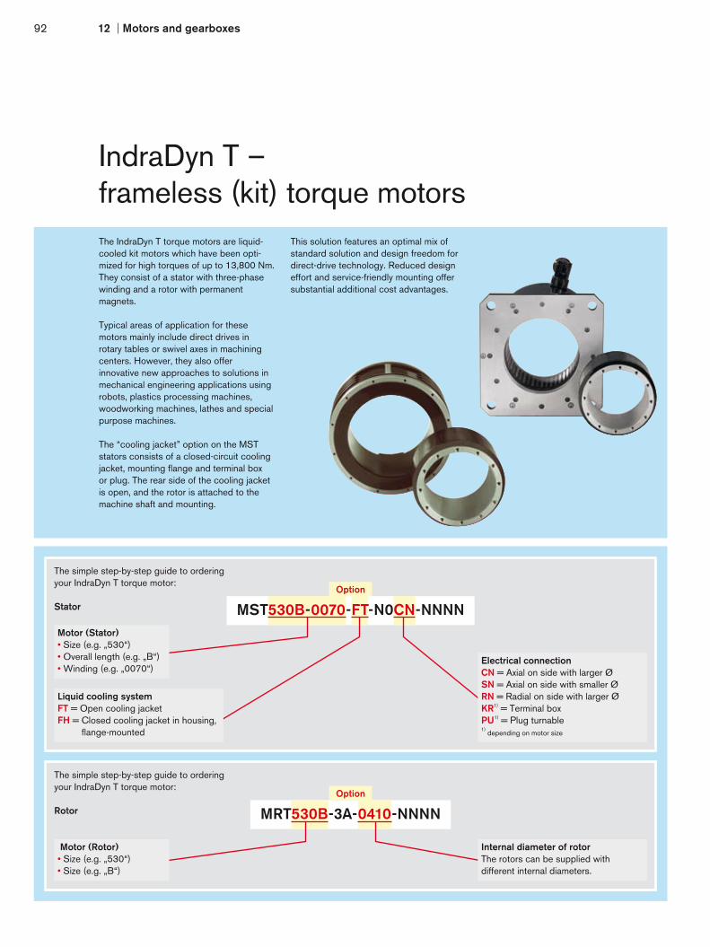
92 12 Motors and gearboxes
IndraDyn T –frameless (kit) torque motorsThe IndraDyn T torque motors are liquid- cooled kit motors which have been opti- mized for high torques of up to 13,800 Nm. They consist of a stator with three-phase winding and a rotor with permanent magnets.
Typical areas of application for these motors mainly include direct drives in rotary tables or swivel axes in machining centers. However, they also offer innovative new approaches to solutions in mechanical engineering applications using robots, plastics processing machines, woodworking machines, lathes and special purpose machines.
The “cooling jacket” option on the MSTstators consists of a closed-circuit coolingjacket, mounting flange and terminal boxor plug. The rear side of the cooling jacketis open, and the rotor is attached to the machine shaft and mounting.
This solution features an optimal mix ofstandard solution and design freedom fordirect-drive technology. Reduced designeffort and service-friendly mounting offersubstantial additional cost advantages.
The simple step-by-step guide to ordering your IndraDyn T torque motor:
Stator
Electrical connectionCN = Axial on side with larger ØSN = Axial on side with smaller ØRN = Radial on side with larger ØKR1) = Terminal boxPU1) = Plug turnable1)
depending on motor size
Motor (Stator)• Size (e.g. „530“)• Overall length (e.g. „B“)• Winding (e.g. „0070“)
Liquid cooling systemFT = Open cooling jacketFH = Closed cooling jacket in housing,
flange-mounted
The simple step-by-step guide to ordering your IndraDyn T torque motor:
Rotor
Internal diameter of rotorThe rotors can be supplied withdifferent internal diameters.
Motor (Rotor)• Size (e.g. „530“)• Size (e.g. „B“)
Option
MST530B-0070-FT-N0CN-NNNN
Option
MRT530B-3A-0410-NNNN

Your benefit
B
ØAØC
D E
ØC
MN
nNnMMax nMax
MMax
Current
Pow
er
IndraDyn T
Conventionaltorque motors
Speed
Torq
ue
IndraDyn T
Conventionaltorque motors
1293
Mot
ors
and
gear
boxe
s
Powerful and directMaximum l torques of up to 13,800 NmFull l torque even at standstillExtremely l high overload capacityLiquid l cooling with thermal encapsulation Easy l to assemble
Motor Ratedtorque
Maximumtorque
Speedat MMax
Ratedspeed
Ratedcurrent
Maximumcurrent
Moment of inertia (Rotor)1)
Dimensions Mass2)
MN [Nm]
MMax
[Nm]nMMax
[rpm]nN
[rpm]IN
[A]IMax
[A]JR
[kgm2]Ø A
[mm]B
[mm]Ø C
[mm] D
[mm]E
[mm]m
[kg]
MST130
A-0200 9 15 900 2,000 7.5 16 0.0008
150
63
60
– –
2.4/0.65
C-0050 25 40 225 500 7.5 120.0018 103 5.1/1.5
C-0200 25 40 900 2,000 15.2 38
E-0020 42 65 90 200 7.5 12 0.0029 143 7.7/2.2
MST160A-0050 35 90 180 500 6.5 20 0.0059
18095
805.6/2.4
C-0050 70 180 180 500 13 40 0.0108 145 9.6/4.3
E-0050 105 270 180 500 19.5 60 0.0158 195 13.9/6.2
MST210
A-0027 50 100 100 270 7 25 0.012
230
75
120 260
140 7.2/3
C-0027120 250
100 270 13 500.023 120 185 11.5/4.8
C-0050 200 500 25 100
D-0070 150 300 270 700 32 120 0.027 150 215 13.8/5.8
E-0027 240 500 100 270 24 90 0.042 195 260 18.8/7.8
MST290
B-0018 220 460 70 180 14.8 60 0.08
310
105
200 385
172 13.5/6.2
D-0002350 700
10 25 6.3 250.11 135 202 20/9D-0004 17 45 10.4 30
D-0018 70 180 26 100
E-0004575 1,150
16 40 12.5 500.17 195 262 25.1/11.6
E-0018 70 180 35 125
MST360
B-0018 375 900 70 180 20 70 0.19
385
120
260 450
195 23/9.8
D-0012525 1,150
45 120 16.5 600.27 150 225 28.8/13.5
D-0018 70 180 28 100
E-0018 875 1,900 70 180 42 141 0.44 210 285 40.3/20.9
MST450
B-0012 540 1,200 45 120 22 70 0.45
480
120
350 570
200 31/13
D-0006810 1,800
25 60 18.8 500.64 150 230 38.7/17.9
D-0012 45 120 33 100
E-00061,400 3,250
25 60 32 881.01 210 290 54.2/27.7
E-0012 45 120 46 125
MST530
B-0010 800 1,800 45 100 28.6 71 0.92
565
120
410 645
200 36/22
C-0010 1,200 2,700 40 100 31.2 88 1.25 150 230 45/27.5
E-0010 2,100 4,700 40 100 64 212 1.92 210 290 63/38.5
G-0006 4,200 9,200 25 60 76 2403.84 455 144/77
G-0007 4,200 9,200 28 70 96 305 370
L-0006 6,300 13,800 25 60 120 3805.76
520605 205/115
L-0007 6,300 13,800 28 70 133 420 520
All the specifications given are based on operation with liquid cooling and 540 V DC bus voltage 1) depends on rotor version 2) stator/rotor
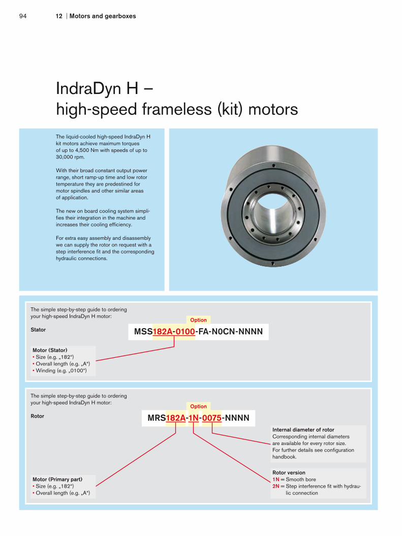
94 12 Motors and gearboxes
IndraDyn H –high-speed frameless (kit) motorsThe liquid-cooled high-speed IndraDyn Hkit motors achieve maximum torquesof up to 4,500 Nm with speeds of up to30,000 rpm.
With their broad constant output powerrange, short ramp-up time and low rotortemperature they are predestined formotor spindles and other similar areasof application.
The new on board cooling system simpli- fies their integration in the machine and increases their cooling efficiency.
For extra easy assembly and disassemblywe can supply the rotor on request with astep interference fit and the correspondinghydraulic connections.
The simple step-by-step guide to ordering your high-speed IndraDyn H motor:
Stator
Motor (Stator)• Size (e.g. „182“)• Overall length (e.g. „A“)• Winding (e.g. „0100“)
The simple step-by-step guide to ordering your high-speed IndraDyn H motor:
Rotor
Internal diameter of rotorCorresponding internal diameters are available for every rotor size. For further details see configuration handbook.
Motor (Primary part)• Size (e.g. „182“)• Overall length (e.g. „A“)
Rotor version1N = Smooth bore2N = Step interference fit with hydrau-
lic connection
Option
MSS182A-0100-FA-N0CN-NNNN
Option
MRS182A-1N-0075-NNNN

Your benefit
B
ØAØC
MN
PN
nN nMax
Speed
Conventional synchronousmotors
1 2 3 4 5 6
Pow
er
IndraDyn H
Speed
Torq
ue
Asynchronous motors
IndraDyn H
1295
Mot
ors
and
gear
boxe
s
High dynamics and precisionMaximum l torques up to 4,500 NmMaximum l speeds up to 30,000 rpmWide l constant output power rangeIntegrated l cooling systemStraightforward l integration in the machine
Motor Ratedspeed
Maximumspeed
Ratedtorque
Maximumtorque
Ratedpower
Ratedcurrent
Maximumcurrent
Moment of inertia (Rotor)1)
Dimensions Mass2)
nN
[rpm]nMax
[rpm]MN
[Nm]MMax
[Nm]PN
[kW]IN
[A]IMax
[A]JR
[kgm2]Ø A
[mm]B
[mm]Ø C1)
[mm]m
[kg]
MSS102
B-0800 8,000 30,000 10.5 30 8.8 18 40 0.003
120
156
46
7.7/2.1
D-0800 8,000 30,000 20 45 16.8 24 69 0.004 206 10.1/3.1
F-0300 3,000 18,000 32 75 10.1 15.3 350.006 306 14.9/5.1
F-0800 8,000 30,000 26 68 21.8 43 100
MSS142B-0700 7,000 28,000 27.5 67 20.2 45 100 0.011
160181
5816.7/4.6
D-0700 7,000 28,000 40.5 90 29.7 65 140 0.014 231 21.2/6.5
F-0700 7,000 28,000 53 113 38.9 84 180 0.017 281 25.7/8.3
MSS162
B-0400 4,000 20,000 50 115 20.9 42 110 0.014
180
206
68
22/6.9
D-0400 4,000 20,000 70 160 29.3 64 170 0.018 256 28.1/8.8
F-0310 3,100 15,500 90 200 29.2 64 170 0.022 306 34.1/10.6
J-0200 2,000 10,000 120 275 25.1 64 170 0.028 381 46.1/13.4
MSS182
A-0100 1,000 6,000 12 30 1.3 3.7 110.0089
200
82
85
6.9/2.7A-0250 2,500 12,000 12 30 3.1 5 15
B-0280 2,800 12,000 100 230 29.3 64 170 0.031 232 32.1/9.6
D-0260 2,600 12,000 140 320 38.1 71 200 0.039 282 38.9/11.8
F-0200 2,000 12,000 200 450 41.9 71 200 0.053 382 52.6/21.3
MSS202
A-0200 2,000 11,000 105 270 22 45 130 0.05
220
215
96
33/12.8
B-0150 1,500 8,200 140 390 22 52 1410.064 265 40.7/16.2
B-0210 2,100 11,500 140 390 30.8 68 180
D-0170 1,700 9,300 175 480 31.2 68 180 0.077 315 48.3/19.6
D-0360 3,600 8,000 136 333 51.3 98 210 0.077 315 48.3/19.6
F-0120 1,200 6,600 245 650 30.8 68 180 0.104 415 63.7/26.9
MSS242B-0100 1,000 6,000 250 575 26.2 68 180 0.119
270275
11066.7/22.5
D-0070 700 4,200 375 860 27.5 49.5 180 0.167 375 92.3/31.7
F-0060 600 3,600 425 970 26.7 68 180 0.193 425 105.1/36.5
MSS272
B-0065 650 3,000 400 900 27.2 71 2000.268
300
330
135
90.4/35.5B-0080 800 3,200 400 900 33.5 82 250
D-0050 500 2,200 525 1,200 27.5 71 200 0.335 405 112.3/44.5
F-0040 400 1,800 650 1,500 27.2 71 200 0.403 480 134.2/53.5
MSS312
B-0035 350 1,500 650 1,550 23.8 62.5 170 0.617
340
380
170
128.7/55
D-0028 280 1,200 820 1,950 24 59.5 1600.751
455154.1/67.4
D-0060 600 2,400 820 1,950 51.5 93.2 250 455
F-0028 280 1,200 975 2,275 28.6 62 180 0.885 530 179.5/79.5
H-0025 250 1,100 1,125 2,750 29.5 62 1801.064 630 215/95.6
H-0085 850 3,400 1,100 2,750 97.9 197 570
MSS382B-0025 250 1,000 1,375 2,875 36 85 250 1.525
405430
240178.5/77.6
D-0020 200 800 1,775 3,700 37.2 101 250 1.911 530 220.1/97.2
F-0018 180 720 2,170 4,500 40.9 83.6 250 2.296 630 262/120
MSS482 A-0200 2,000 5,000 120 275 25.1 40 140 0.604 510 115 345 59/16.2
All the specifications given are based on operation with liquid cooling and 540 V DC bus voltage. The indicated maximum speed is reached at a DC bus voltage of 750 V1) depends on rotor version 2) stator/rotor with largest available internal diameter of rotor
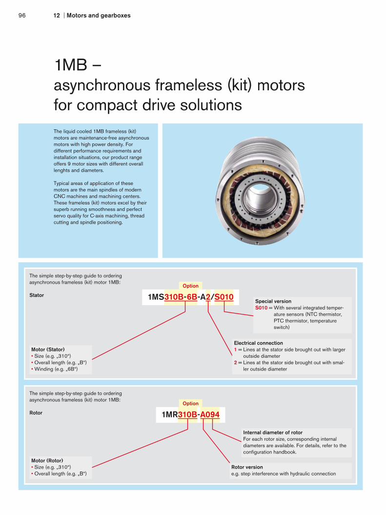
96 12 Motors and gearboxes
1MB – asynchronous frameless (kit) motorsfor compact drive solutionsThe liquid cooled 1MB frameless (kit)motors are maintenance-free asynchronousmotors with high power density. For different performance requirements and installation situations, our product range offers 9 motor sizes with different overall lenghts and diameters.
Typical areas of application of these motors are the main spindles of modern CNC machines and machining centers. These frameless (kit) motors excel by their superb running smoothness and perfect servo quality for C-axis machining, thread cutting and spindle positioning.
The simple step-by-step guide to ordering asynchronous frameless (kit) motor 1MB:
Rotor
Internal diameter of rotorFor each rotor size, corresponding internal diameters are available. For details, refer to the configuration handbook.
Motor (Rotor)• Size (e.g. „310“)• Overall length (e.g. „B“)
Rotor versione.g. step interference with hydraulic connection
The simple step-by-step guide to ordering asynchronous frameless (kit) motor 1MB:
StatorSpecial versionS010 = With several integrated temper-
ature sensors (NTC thermistor, PTC thermistor, temperature switch)
Motor (Stator)• Size (e.g. „310“)• Overall length (e.g. „B“)• Winding (e.g. „6B“)
Electrical connection1 = Lines at the stator side brought out with larger
outside diameter2 = Lines at the stator side brought out with smal-
ler outside diameter
Option
1MS310B-6B-A2/S010
Option
1MR310B-A094

Your benefit
B
ØA
ØC
MN
PN
nN nMax
1297
Mot
ors
and
gear
boxe
s
Robust and reliableRated l torques up to 875 NmMaximum l speeds up to 20,000 rpmLarge l spindle cutoffExcellent l running smoothness Easy l integration into the machine
Motor Ratedspeed
Maximumspeed
Ratedtorque
Ratedpower
Ratedcurrent
Momentof inertia (Rotor)
Dimensions Mass2)
nN
[rpm]nMax
[rpm]MN
[Nm]PN
[kW]IN
[A]JR
[kgm2]Ø A
[mm]B
[mm]Ø C1)
[mm]m
[kg]
1MS105N-4A 4,500 15,000 17 7 29
0.0033 120 350 40.5 11.2/2.8N-4B 2,400 12,000 22 5.5 16.4
1MS140
B-4A 7,500 20,000 7 5.5 180.0044
160
150
45
5.3/3.3B-4B 5,000 20,000 7 3.7 25
D-4B 4,000 16,000 14 6 43 0.0061 190 8.2/4.5
F-4A 3,000 15,000 24 7.5 43 0.0082 240 11.8/6.1
H-4B 3,000 15,000 34 10.5 58 0.0103 290 15.5/7.3
1MS160
B-4A 3,000 12,000 16 5 36 0.0084
180
160
60
6.8/5.3
D-4A 3,000 12,000 32 10 480.0121 205 11.1/7.3
D-4B 2,000 8,000 32 6.7 23.8
E-4B 1,000 4,000 33 3.5 19 0.0149 240 14.4/9.4
F-4A 3,000 12,000 48 15 740.0161 255 15.8/10.2F-4B 3,000 12,000 48 15 45
F-4D 2,500 10,000 48 12.5 23.2
H-4A 3,000 12,000 64 20 58 0.0201 310 21/9.8
N-4A 3,000 12,000 89 28 750.0267 385 28.1/12.7N-4B 2,000 8,000 89 18.6 60
N-4C 1,500 6,000 89 14 26
1MS200
C-4A 1,500 6,000 57 9 50 0.041
220
240
66
21/15
D-4B 1,500 6,000 85 13.5 48
0.037 295 29/19D-4C 5,000 20,000 59 31 75
D-4D 2,500 10,000 85 22 59
D-4E 1,500 6,000 85 13.5 84
D-4F 6,000 18,000 49 31 82
E-4B 1,800 7,200 85 16 41.40.059 330 34/22
E-4C 3,900 15,600 74 30.2 65
H-4B 1,500 6,000 124 19.5 680.069 380 41/26
H-4D 1,500 6,000 124 19.5 52.6
1MS240B-4A 1,000 4,000 62 6.5 46 0.078
270270
7229/19
F-4A 1,000 4,000 123 13 74 0.12 360 48/29
H-4B 1,000 4,000 169 18 56 0.153 430 62/37
1MS241
D-6A 1,000 4,000 112 12 620.135
270
290
111
38/24D-6C 1,000 4,000 112 12 27
H-6C 1,800 7,200 202 32 75.50.227 410 63/39H-6D 850 3,400 202 18 66.4
H-6G 800 3,200 202 16.9 39.7
1MS242 N-4B 1,700 6,800 185 33 98 0.135 270 440 71 81/37
1MS270 C-4B 1,500 6,000 190 30 96 0.258 300 400 120 82/52
1MS310
B-6B 1,000 4,000 260 27 750.477
340
385
125
84/65B-6D 700 2,800 260 19 81
B-6E 440 1,760 260 12 58
D-6B 800 3,200 340 28.5 81 0.492 450 108/80
F-6A 400 1,600 480 20 610.723 520 133/97
F-6B 900 3,600 480 35 111
1MS375B-6B 600 2,400 636 40 120 1.39
405520
170162/106
D-6B 600 2,400 875 55 1501.73 620 205/132
D-6D 300 1,200 875 27.5 94
All the specifications given are based on operation with liquid cooling and 540 V DC bus voltage. 1) available diameters depend on rotor version 2) stator/rotor

98 12 Motors and gearboxes
GTE – planetary gearboxesfor standard applicationsTogether with our dynamic MSK motors,the compact GTE range of planetarygearboxes guarantees high torques inall standard applications.
Typical areas of application include simplehandling and automation systems withrack-and-pinion drives or synchronous beltdrives.
Virtually all performance requirements canbe met in these applications thanks tothe subtle staggering of sizes and the highpower density of the GTE gearboxes.
The single-stage or two-stage gearboxescan be supplied with a plain shaft orkeyway.
The simple step-by-step guide to ordering your GTE planetary gearboxes:
Gear range1 = Single-stage2 = Two-stage
Gears• Size (e.g. „040“)
Output shaft and backlashA = With keywayB = Plain shaft
Option
GTE060-NN1-004A-NN03
Motor/gearbox combination
Motor GTE040 GTE060 GTE080 GTE120 GTE160
MS
K
030 – NN02 NN02 – –
040 – – NN03 NN03 –
050 – – – NN20 NN20
060 – – – NN211) NN21
061 – – – NN051) NN05
070 – – – – NN16
071 – – – – NN16
075 – – – – NN16
076 – – – – NN06
100 – – – – NN091)
KS
M
041 – – NN03 NN03 –
061 – – – NN051) NN05
071 – – – – NN16
076 – – – – NN06
MS
M
019A NN45 – – – –
019B NN45 – – – –
031B – NN42 – – –
031C – – NN43 – –
041B – – NN44 NN44 –1) combination only possible with single-stage gearboxes

Your benefit
1299
Mot
ors
and
gear
boxe
s
Economical and compactIdeal l for standard applicationsLow l backlashOpen l choice of mounting positionsSilent l operationLifetime l lubrication
Gears Transmis-sionratio
Nominal input speed
Maximuminput
speed6)
Maximumoutputspeed
Nominalinput
torque
Nominaloutputtorque MOUT nom
1) 2) 3)
Maximuminput
torque
Maximumoutputtorque
1) 2) 3) 4)
Backlash Torsionstiffness
Efficiency 5)
Mass moment of
inertia
Mass
at 50 % MOUT nom
6)
at 100 % MOUT nom
6)
nIN N
[rpm]nIN N
[rpm]nIN MAX
[rpm]nOUT MAX
[rpm]MIN N
[Nm]MOUT N
[Nm]MIN MAX
[Nm]MOUT MAX
[Nm]–
[arcmin]D
[Nm/arcmin]η
[%]J
[kgcm2]m
[kg]
GTE040
single-stage
3 5,000 5,000 18,000 6,000 3.67 11 5.9 17.6
< 24 1 96
0.031
0.354 5,000 5,000 18,000 4,500 3.75 15 6 24 0.022
5 5,000 5,000 18,000 3,600 2.8 14 4.4 22 0.019
8 5,000 5,000 18,000 2,250 0.75 6 1.25 10 0.017
two-stage
12 5,000 5,000 18,000 1,500 1.67 20 2.7 32< 28 1.1 94
0.0290.4520 5,000 5,000 18,000 900 1 20 1.6 32 0.019
40 5,000 5,000 18,000 450 0.45 18 0.73 29 0.016
GTE060
single-stage
3 4,500 4,450 13,000 4,333 9.3 28 15 45
< 16 2.3 96
0.135
0.94 4,500 4,400 13,000 3,250 9.5 38 15.25 61 0.093
5 4,500 4,500 13,000 2,600 8 40 12.8 64 0.078
8 4,500 4,500 13,000 1,625 2.25 18 3.63 29 0.065
two-stage
12 4,500 4,500 13,000 1,083 3.7 44 5.83 70< 20 2.5 94
0.1271.120 4,500 4,500 13,000 650 2.2 44 3.5 70 0.075
40 4,500 4,500 13,000 325 1 40 1.6 64 0.064
GTE080
single-stage
3 3,900 2,400 7,000 2,333 28.3 85 45.3 136
< 9 6 96
0.77
2.14 3,650 2,150 7,000 1,750 28.7 115 46 184 0.52
5 4,000 2,650 7,000 1,400 22 110 35.2 176 0.45
8 4,000 4,000 7,000 875 6.2 50 10 80 0.39
two-stage
12 4,000 3,450 7,000 583 10 120 16 192< 14 6.5 94
0.722.620 4,000 4,000 7,000 350 6 120 9.6 192 0.44
40 4,000 4,000 7,000 175 2.75 110 4.4 176 0.39
GTE120
single-stage
3 3,500 2,500 6,500 2,167 38.3 115 61.3 184
< 8 12 96
2.63
64 3,500 2,250 6,500 1,625 38.75 155 62 248 1.79
5 3,500 2,250 6,500 1,300 39 195 62.4 312 1.53
8 3,500 3,500 6,500 813 15 120 24 192 1.32
two-stage
12 3,500 2,500 6,500 542 21.7 260 34.7 416< 12 13 94
2.56820 3,500 3,500 6,500 325 13 260 20.8 416 1.5
40 3,500 3,500 6,500 163 5.75 230 9.2 368 1.3
GTE160
single-stage
3 1,700 1,000 6,500 2,167 133.3 400 213.3 640
< 6 38 96
12.14
184 1,700 1,000 6,500 1,625 112.5 450 180 720 7.78
5 2,000 1,150 6,500 1,300 90 450 144 720 6.07
8 2,950 1,750 6,500 813 56.25 450 90 720 4.63
two-stage
12 1,950 1,050 6,500 542 66.7 800 106.7 1,280< 10 41 94
12.372220 2,700 1,500 6,500 325 40 800 64 1,280 6.65
40 3,000 2,950 6,500 163 17.5 700 28 1,120 5.281) these values refer to a speed of the output shaft of 100 min-1 on duty cycle KA = 1 and S1-mode for electrical machines and T = 30 °C 2) depends on the motor shaft diameter3) with key, at tumescent load4) allowable for 30.000 revolutions and output shaft5) depends on ratio, for speed of output shaft = 100 rpm6) allowed operating temperature must be observed

100 12 Motors and gearboxes
GTM – planetary gearboxesfor maximum performanceCharacterized by a particularly highpower density and low backlash, thehigh-precision GTM range of planetarygearboxes has been designed formounting directly on servo motors.
Their high degree of efficiency makesthese gearboxes suitable for theS1 continuous operation and thereforeideal for use in printing presses, forexample.
Combined with the dynamic IndraDynmotors they achieve the highest speeds,acceleration and optimum positioningaccuracy.
The single-stage or two-stage gearboxescan be supplied with a plain shaft or keyway and also with reduced backlashon request.
The simple step-by-step guide to ordering your GTM planetary gearbox:
Gear range1 = Single-stage2 = Two-stage
Gears• Size (e.g. „075“)
Output shaft and backlashA = With keywayB = Plain shaftC = Keyway and reduced backlashD = Plain shaft and reduced backlash
Option
GTM075-NN1-004A-NN03
Motor/gearbox combination
Motor GTM060 GTM075 GTM100 GTM140 GTM180 GTM240
MS
K
030 NN02 – – – – –
040 NN03 NN03 – – – –
050 – NN20 NN20 NN20 – –
060 – NN21 NN21 NN21 – –
061 – NN05 NN05 NN05 – –
070 – – NN16 NN16 NN16 –
071 – – NN16 NN61 NN16 –
075 – – NN16 NN61 NN16 –
076 – – NN06 NN06 – –
100 – – – NN09 NN09 –
101 – – – NN19 NN19 –
103 – – – NN19 NN19 –
131 – – – – NN151) NN151)
KS
M
041 NN03 NN03 NN03 – – –
061 – NN05 NN05 NN05 – –
071 – – NN16 NN16 NN16 –
076 – – NN06 NN06 – –
MA
D
100 – – – NN09 NN09 –
130 – – – – NN111) NN111)
160 – – – – – NN121)
MA
F 100 – – – – NN08 –
130 – – – – NN111) NN111)
1) combination only possible with single-stage gearboxes

Your benefit
12101
Mot
ors
and
gear
boxe
s
High-precision and flexibilityHigh-precision l gearing for highest positioning accuracy Minimum l power dissipation in continuous operation Optimized l gear tooth forming for silent operationEnvironment-resistant, l hermetically sealed housing High l acceleration torque is achievable through a compact and rigid construction
Gears Transmissionratio
Nominalinputspeed
Maximuminputspeed
Maximumoutputspeed
Nominalinput
torque
Nominaloutputtorque
Maximuminput
torque
Maximumoutputtorque
Backlashstandard/reduced
Torsionstiffness
Efficiency Mass moment of
inertia
Mass
nIN N
[rpm]nIN Max
[rpm]nOUT Max
[rpm]MIN N
[rpm]MOUT N
[Nm]MIN Max
[Nm]MOUT Max
[Nm]–
[arcmin]D
[Nm/arcmin]η
[%]J
[kgcm2]m
[kg]
GTM060
single-stage
4 3,000 5,000 1,250 6.25 25 12.5 50
≤ 6/≤ 3
3.5
≥ 97
0.16
1.65 4,000 6,300 1,260 5 25 10 50 0.16
7 5,000 8,000 1,143 3.6 25 7.1 50 0.15
10 6,000 10,000 1,000 2 20 4 40 0.14
two-stage
20 4,000 6,300 315 1.25 25 2.5 50≤ 8/≤ 6 ≥ 94
0.122.2
50 6,000 10,000 200 0.5 25 1 50 0.1
GTM075
single-stage
4 3,000 5,000 1,250 21.3 85 42.5 170
≤ 6/≤ 3
8.2
≥ 97
0.55
2.95 4,000 6,300 1,260 20 100 40 200 0.47
7 5,000 8,000 1,143 12.1 85 24.3 170 0.41
10 6,000 10,000 1,000 6 60 11 110 0.38
two-stage
20 4,000 6,300 315 4.25 85 8.5 170≤ 8/≤ 6 ≥ 94
0.473.8
50 6,000 10,000 200 2 100 4 200 0.47
GTM100
single-stage
3 2,300 4,000 1,333 40 120 73.3 220
≤ 4/≤ 2
24
≥ 97
2.8
5.7
4 2,500 4,000 1,000 42.5 170 85 340 2
5 3,000 5,000 1,000 40 200 80 400 1.64
7 4,000 6,300 900 24.3 170 48.6 340 1.36
10 5,000 8,000 800 12 120 22 220 1.22
two-stage
20 3,000 5,000 250 8.5 170 17 340≤ 6/≤ 4 ≥ 94
1.567.5
50 5,000 8,000 160 4 200 8 400 1.44
GTM140
single-stage
3 1,800 3,200 1,067 93.3 280 186.7 560
≤ 4/≤ 2
48
≥ 97
8.2
11.5
4 2,000 3,200 800 105 420 210 840 6.75
5 2,500 4,000 800 100 500 200 1,000 5.54
7 3,000 5,000 714 60 420 120 840 4.59
10 4,000 6,300 630 28 280 56 560 4.1
two-stage
20 2,500 4,000 200 21 420 42 840≤ 6/≤ 4 ≥ 94
5.2915
50 4,000 6,300 126 10 500 20 1,000 4.96
GTM180
single-stage
3 1,300 2,500 833 240 720 480 1,440
≤ 4/≤ 2
148
≥ 97
36
27
4 1,500 2,500 625 255 1,020 510 2,040 24.5
5 2,000 3,200 640 240 1,200 480 2,400 18.8
7 2,500 4,000 571 145.7 1,020 291,4 2,040 14.5
10 3,000 5,000 500 72 720 144 1,440 12.3
two-stage
20 2,000 3,200 160 51 1,020 102 2,040≤ 6/≤ 4 ≥ 94
6.9535
50 3,000 5,000 100 24 1,200 48 2,400 5.45
GTM240 single-stage
3 800 2,000 667 600 1,800 1,000 3,000
≤ 4/≤ 2 340 ≥ 97
128
62
4 1,000 2,000 500 625 2,500 1,250 5,000 97.6
5 1,200 2,500 500 600 3,000 1,200 6,000 76.4
7 1,500 3,000 429 357.1 2,500 714,3 5,000 59.9
10 2,000 3,500 350 180 1,800 300 3,000 51.1
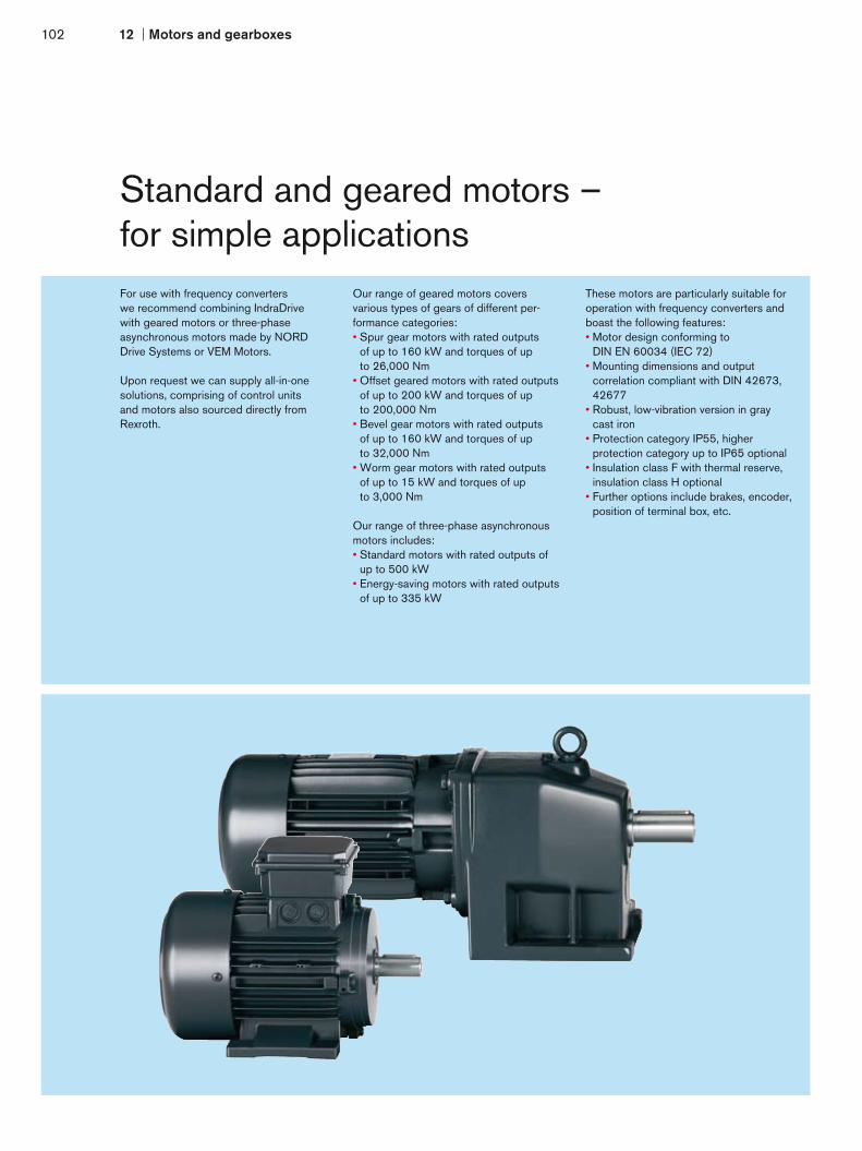
102 12 Motors and gearboxes
Standard and geared motors –for simple applicationsFor use with frequency converterswe recommend combining IndraDrivewith geared motors or three-phaseasynchronous motors made by NORDDrive Systems or VEM Motors.
Upon request we can supply all-in-onesolutions, comprising of control unitsand motors also sourced directly fromRexroth.
Our range of geared motors coversvarious types of gears of different per-formance categories:• Spur gear motors with rated outputs
of up to 160 kW and torques of up to 26,000 Nm
• Offset geared motors with rated outputs of up to 200 kW and torques of up to 200,000 Nm
• Bevel gear motors with rated outputs of up to 160 kW and torques of up to 32,000 Nm
• Worm gear motors with rated outputs of up to 15 kW and torques of up to 3,000 Nm
Our range of three-phase asynchronousmotors includes:• Standard motors with rated outputs of
up to 500 kW• Energy-saving motors with rated outputs
of up to 335 kW
These motors are particularly suitable foroperation with frequency converters andboast the following features:• Motor design conforming to
DIN EN 60034 (IEC 72)• Mounting dimensions and output
correlation compliant with DIN 42673, 42677
• Robust, low-vibration version in gray cast iron
• Protection category IP55, higher protection category up to IP65 optional
• Insulation class F with thermal reserve, insulation class H optional
• Further options include brakes, encoder, position of terminal box, etc.

12103
Mot
ors
and
gear
boxe
s
Cross reference for IEC standard motors
Mechanicalmotor output PNenn
INenn cos ϕ η Continuous operation INenn (>10 min)
Overload operation 1,1 x INenn (1 min)
INenn (9 min)
Overload operation 1,5 x INenn (1 min)
INenn (4 min)
Overload operation 2 x INenn (2 s) INenn (18 s)
1.1 kW 2.6 A 0.79 76.6 %
HCS02.1E-W0012
HMS01.1N-W0020
HMD01.1N-W0012
HCS02.1E-W0012
HMS01.1N-W0020
HMD01.1N-W0012
HCS02.1E-W0012
HMS01.1N-W0020
HMD01.1N-W0012
HCS02.1E-W0012
HMS01.1N-W0020
HMD01.1N-W0012
1.5 kW 3.4 A 0.81 78.8 %
HCS02.1E-W0012
HMS01.1N-W0020
HMD01.1N-W0012
HCS02.1E-W0012
HMS01.1N-W0020
HMD01.1N-W0012
HCS02.1E-W0028
HMS01.1N-W0020
HMD01.1N-W0012
HCS02.1E-W0028
HMS01.1N-W0020
HMD01.1N-W0012
2.2 kW 5.2 A 0.76 81 %
HCS02.1E-W0028
HMS01.1N-W0020
HMD01.1N-W0012
HCS02.1E-W0028
HMS01.1N-W0020
HMD01.1N-W0012
HCS02.1E-W0028
HMS01.1N-W0020
HMD01.1N-W0012
HCS02.1E-W0028
HMS01.1N-W0020
HMD01.1N-W0012
3 kW 6.7 A 0.79 82 %
HCS02.1E-W0028
HMS01.1N-W0020
HMD01.1N-W0012
HCS02.1E-W0028
HMS01.1N-W0020
HMD01.1N-W0020
HCS02.1E-W0028
HMS01.1N-W0020
HMD01.1N-W0020
HCS02.1E-W0028
HMS01.1N-W0020
HMD01.1N-W0020
4 kW 8.8 A 0.78 84.2 %
HCS02.1E-W0028
HMS01.1N-W0020
HMD01.1N-W0020
HCS02.1E-W0028
HMS01.1N-W0020
HMD01.1N-W0020
HCS02.1E-W0028
HMS01.1N-W0036
HMD01.1N-W0036
HCS02.1E-W00541)
HMS01.1N-W0036
HMD01.1N-W0036
5.5 kW 11.8 A 0.77 85.7 %
HCS02.1E-W00541)
HMS01.1N-W0020
HMD01.1N-W0036
HCS02.1E-W00541)
HMS01.1N-W0036
HMD01.1N-W0036
HCS02.1E-W00541)
HMS01.1N-W0036
HMD01.1N-W0036
HCS02.1E-W00541)
HMS01.1N-W0036
HMD01.1N-W0036
7.5 kW 15 A 0.84 87 %
HCS02.1E-W00541)
HMS01.1N-W0036
HMD01.1N-W0036
HCS02.1E-W00541)
HMS01.1N-W0036
HMD01.1N-W0036
HCS02.1E-W00701)
HMS01.1N-W0036
HMD01.1N-W0036
HCS02.1E-W00701)
HMS01.1N-W0036
HMD01.1N-W0036
11 kW 21 A 0.85 88.4 %HCS02.1E-W00701)
HMS01.1N-W0036
HCS02.1E-W00701)
HMS01.1N-W0054
HCS02.1E-W00701)
HMS01.1N-W0054
HCS03.1E-W00701)
HMS01.1N-W0054
15 kW 28 A 0.86 89.4 %HCS03.1E-W00701)
HMS01.1N-W0054
HCS03.1E-W00701)
HMS01.1N-W0054
HCS03.1E-W00701)
HMS01.1N-W0070
HCS03.1E-W00701)
HMS01.1N-W0070
18.5 kW 34.5 A 0.86 90 %HCS03.1E-W00701)
HMS01.1N-W0054
HCS03.1E-W00701)
HMS01.1N-W0070
HCS03.1E-W01001)
HMS01.1N-W0110
HCS03.1E-W01001)
HMS01.1N-W0110
22 kW 42 A 0.84 90.5 %HCS03.1E-W00701)
HMS01.1N-W0070
HCS03.1E-W01001)
HMS01.1N-W0110
HCS03.1E-W01001)
HMS01.1N-W0110
HCS03.1E-W01001)
HMS01.1N-W0110
30 kW 55.5 A 0.85 91.5 %HCS03.1E-W01001)
HMS01.1N-W0110
HCS03.1E-W01001)
HMS01.1N-W0110
HCS03.1E-W01501)
HMS01.1N-W0150
HCS03.1E-W01501)
HMS01.1N-W0150
37 kW 67 A 0.86 92.5 %HCS03.1E-W01001)
HMS01.1N-W0110
HCS03.1E-W01501)
HMS01.1N-W0150
HCS03.1E-W01501)
HMS01.1N-W0150
HCS03.1E-W01501)
HMS01.1N-W0150
45 kW 81 A 0.86 93 %HCS03.1E-W01501)
HMS01.1N-W0150
HCS03.1E-W01501)
HMS01.1N-W0150
HCS03.1E-W02101)
HMS01.1N-W0210
HCS03.1E-W02101)
HMS01.1N-W0210
55 kW 98.5 A 0.86 93.5 %HCS03.1E-W02101)
HMS01.1N-W0150
HCS03.1E-W02101)
HMS01.1N-W0210
HCS03.1E-W02101)
HMS01.1N-W0210
HCS03.1E-W02101)
HMS01.1N-W0210
75 kW 134 A 0.86 94.1 %HCS03.1E-W02101)
HMS01.1N-W0210
HCS03.1E-W02101)
HMS01.1N-W0210HMS01.1N-W03502) HMS01.1N-W03502)
90 kW 160 A 0.86 94.6 % HMS01.1N-W03502) HMS01.1N-W03502) HMS01.1N-W03502) HMS01.1N-W03502)
110 kW 194 A 0.86 95.1 % HMS01.1N-W03502) HMS01.1N-W03502) – –
132 kW 233 A 0.86 95.1 % HMS01.1N-W03502) HMS01.1N-W03502) – –The examples apply to operation of 4-pole standard motors 3 AC 400 V/60 Hz at 4 kHz switching frequency and a rotary frequency > 4 Hz.An external fan may be necessary depending on your application.1) with HNL power choke2) preliminary
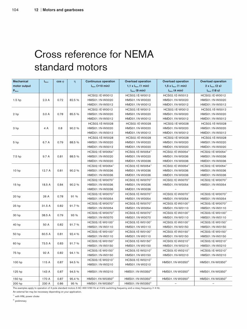
104 12 Motors and gearboxes
Cross reference for NEMA standard motors
Mechanicalmotor output PNenn
INenn cos ϕ ηη Continuous operation INenn (>10 min)
Overload operation 1,1 x INenn (1 min)
INenn (9 min)
Overload operation 1,5 x INenn (1 min)
INenn (4 min)
Overload operation 2 x INenn (2 s) INenn (18 s)
1.5 hp 2.3 A 0.72 82.5 %
HCS02.1E-W0012
HMS01.1N-W0020
HMD01.1N-W0012
HCS02.1E-W0012
HMS01.1N-W0020
HMD01.1N-W0012
HCS02.1E-W0012
HMS01.1N-W0020
HMD01.1N-W0012
HCS02.1E-W0012
HMS01.1N-W0020
HMD01.1N-W0012
2 hp 3.0 A 0.78 85.5 %
HCS02.1E-W0012
HMS01.1N-W0020
HMD01.1N-W0012
HCS02.1E-W0012
HMS01.1N-W0020
HMD01.1N-W0012
HCS02.1E-W0012
HMS01.1N-W0020
HMD01.1N-W0012
HCS02.1E-W0012
HMS01.1N-W0020
HMD01.1N-W0012
3 hp 4 A 0.8 90.2 %
HCS02.1E-W0028
HMS01.1N-W0020
HMD01.1N-W0012
HCS02.1E-W0028
HMS01.1N-W0020
HMD01.1N-W0012
HCS02.1E-W0028
HMS01.1N-W0020
HMD01.1N-W0012
HCS02.1E-W0028
HMS01.1N-W0020
HMD01.1N-W0012
5 hp 6.7 A 0.79 88.5 %
HCS02.1E-W0028
HMS01.1N-W0020
HMD01.1N-W0012
HCS02.1E-W0028
HMS01.1N-W0020
HMD01.1N-W0020
HCS02.1E-W0028
HMS01.1N-W0020
HMD01.1N-W0020
HCS02.1E-W0028
HMS01.1N-W0020
HMD01.1N-W0020
7.5 hp 9.7 A 0.81 88.5 %
HCS02.1E-W00541)
HMS01.1N-W0020
HMD01.1N-W0020
HCS02.1E-W00541)
HMS01.1N-W0020
HMD01.1N-W0036
HCS02.1E-W00541)
HMS01.1N-W0036
HMD01.1N-W0036
HCS02.1E-W00541)
HMS01.1N-W0036
HMD01.1N-W0036
10 hp 12.7 A 0.81 90.2 %
HCS02.1E-W00541)
HMS01.1N-W0036
HMD01.1N-W0036
HCS02.1E-W00541)
HMS01.1N-W0036
HMD01.1N-W0036
HCS02.1E-W00541)
HMS01.1N-W0036
HMD01.1N-W0036
HCS02.1E-W00541)
HMS01.1N-W0036
HMD01.1N-W0036
15 hp 18.5 A 0.84 90.2 %
HCS02.1E-W00701)
HMS01.1N-W0036
HMD01.1N-W0036
HCS02.1E-W00701)
HMS01.1N-W0036
HMD01.1N-W0036
HCS02.1E-W00701)
HMS01.1N-W0054
–
HCS02.1E-W00701)
HMS01.1N-W0054
–
20 hp 26 A 0.78 91 % HCS03.1E-W00701)
HMS01.1N-W0054
HCS03.1E-W00701)
HMS01.1N-W0054
HCS03.1E-W00701)
HMS01.1N-W0054
HCS03.1E-W00701)
HMS01.1N-W0054
25 hp 31.5 A 0.82 91.7 % HCS03.1E-W00701)
HMS01.1N-W0054
HCS03.1E-W00701)
HMS01.1N-W0054
HCS03.1E-W01001)
HMS01.1N-W0110
HCS03.1E-W00701)
HMS01.1N-W0110
30 hp 38.5 A 0.79 93 % HCS03.1E-W00701)
HMS01.1N-W0070
HCS03.1E-W00701)
HMS01.1N-W0070
HCS03.1E-W01001)
HMS01.1N-W0110
HCS03.1E-W01001)
HMS01.1N-W0110
40 hp 50 A 0.82 91.7 % HCS03.1E-W01001)
HMS01.1N-W0110
HCS03.1E-W01001)
HMS01.1N-W0110
HCS03.1E-W01001)
HMS01.1N-W0150
HCS03.1E-W01501)
HMS01.1N-W0150
50 hp 60.5 A 0.81 92.4 % HCS03.1E-W01001)
HMS01.1N-W0110
HCS03.1E-W01001)
HMS01.1N-W0110
HCS03.1E-W01501)
HMS01.1N-W0150
HCS03.1E-W01501)
HMS01.1N-W0150
60 hp 73.5 A 0.83 91.7 % HCS03.1E-W01501)
HMS01.1N-W0150
HCS03.1E-W01501)
HMS01.1N-W0150
HCS03.1E-W02101)
HMS01.1N-W0210
HCS03.1E-W02101)
HMS01.1N-W0210
75 hp 92 A 0.82 94.1 % HCS03.1E-W01501)
HMS01.1N-W0150
HCS03.1E-W02101)
HMS01.1N-W0150
HCS03.1E-W02101)
HMS01.1N-W0210
HCS03.1E-W02101)
HMS01.1N-W0210
100 hp 115 A 0.87 94.5 % HCS03.1E-W02101)
HMS01.1N-W0210
HCS03.1E-W02101)
HMS01.1N-W0210HMS01.1N-W03502) HMS01.1N-W03502)
125 hp 143 A 0.87 94.5 % HMS01.1N-W0210 HMS01.1N-W03502) HMS01.1N-W03502) HMS01.1N-W03502)
150 hp 170 A 0.87 95.4 % HMS01.1N-W03502) HMS01.1N-W03502) HMS01.1N-W03502) HMS01.1N-W03502)
200 hp 230 A 0.86 95 % HMS01.1N-W03502) HMS01.1N-W03502) – –The examples apply to operation of 4-pole standard motors 3 AC 400 V/60 Hz at 4 kHz switching frequency and a rotary frequency > 4 Hz.An external fan may be necessary depending on your application.1) with HNL power choke2) preliminary

12105
Mot
ors
and
gear
boxe
s

106 13 Auxiliary components
Auxiliary components

Mains filters
Mains filters with integrated mains choke
Mains chokes
Motor filters
Brake resistor
Brake units
Capacity modules
Blower unit
DC chokes
Brake chopper
Other accessories
• Basic accessories for assembly and installation• Shield connection for EMC-compatible connection of the motor cable to the power unit• Control cabinet adapter for combining control units of different depths• Auxiliary capacitor• Electrical adaptors• Flange assembly kit• Control cabinet assembly kit• Modular bus extension to bridge larger distances between drive groups
Your benefit
13107
Aux
iliar
y co
mpo
nent
s
Accessories for all requirementsFilters l and chokes for EMC-proof operationComponents l designed to absorb high braking forces Energy l storage capacitors for dynamic sequencesAccessories l for simplified assembly and installation

H
D W
108 13 Auxiliary components
Mains filters –for HMV power supply unitsand HCS convertersMains filters ensure that the EMC limit values are adhered to and suppress leak- age current generated by line capacitors. Our mains filters are optimally coordinatedwith the power units and are scalable inregards to current, number of drives andmotor cable length. They can be combined with our shielded motor cables for trouble- free operation conforming to EN 61800-3, Class A, Group 2, even with single cable lengths of up to 75 m.
Mains filters for HMV power supply unitsand HCS converters
Continuous current Power dissipation Width W Height H Depth D Mass
A W mm mm mm kg
HNF01.1A-F240-E0051-A-480-NNNN 51 < 89 100 440 262 15
HNF01.1A-M900-E0051-A-480-NNNN 51 < 91 100 440 262 15
HNF01.1A-F240-E0125-A-480-NNNN 125 < 127 150 440 262 18
HNF01.1A-M900-E0125-A-480-NNNN 125 < 174 150 440 262 30
HNF01.1A-F240-E0202-A-480-NNNN 202 < 238 150 440 262 29
HNF01.1A-M900-E0202-A-480-NNNN 202 < 373 250 440 262 37
HNF01.1A-F240-R0026-A-480-NNNN 26 < 73 100 440 262 14
HNF01.1A-M900-R0026-A-480-NNNN 26 < 77 150 440 262 17
HNF01.1A-F240-R0065-A-480-NNNN 65 < 163 150 440 262 25
HNF01.1A-M900-R0065-A-480-NNNN 65 < 157 150 440 262 26
HNF01.1A-F240-R0094-A-480-NNNN 94 < 135 150 440 262 28
HNF01.1A-M900-R0094-A-480-NNNN 94 < 146 150 440 262 29
HNF01.1A-H350-R0180-A-480-NNNN 180 < 305 250 440 262 45
HNS02.1A-Q200-R0023-A-480-NNNN 23 < 75 80 352 265 15
HNF01.1B-A100-E0300-N-480-NNNN 300 60 260 306 135 13
HNF01.1B-A100-E0580-N-480-NNNN 580 125 260 306 135 15
HNF01.1B-A100-E0740-N-480-NNNN 740 210 280 356 170 25
for HCS converters A W mm mm mm kg
NFD03.1-480-007 7 3.9 50 160 90 0.7
NFD03.1-480-016 16 6.4 55 220 90 1
NFD03.1-480-030 30 11.9 60 270 100 1.4
NFD03.1-480-055 55 25.9 90 220 105 2
NFD03.1-480-075 75 30.4 90 240 145 3.5
NFD03.1-480-130 130 38 100 240 160 4.7
NFD03.1-480-180 180 61 130 350 180 10
All data applies to nominal rating at 3 AC 400 V mains voltage. Please see the selection tables on the end of this chapter for exact assignments to the power units.

D
H
W 13109
Aux
iliar
y co
mpo
nent
s
Example of assembly
Mains filters with integrated mains choke –for HCS03 convertersThe combination of mains filter and mainschoke in one unit simplifies assembly andinstallation. It is simply fitted underneaththe converter to form one space-savingunit. It is also a particularly easy way tocomply with the directives contained inEN 61800-3, Class A, Group 2.
Mains filters with integrated mains choke Continuous current
Powerdissipation
Nominalinductance
Capacitance Width W Height H Depth D Mass
A W µH µF mm mm mm kg
HNK01.1A-A075-E0050-A-500-NNNN 50 55 3 x 571 3 x 1.1 125 322.5 251.5 15
HNK01.1A-A075-E0080-A-500-NNNN 80 80 3 x 362 3 x 2.2 225 310 270 20
HNK01.1A-A075-E0106-A-500-NNNN 106 110 3 x 240 3 x 2.2 225 310 270 20
HNK01.1A-A075-E0146-A-500-NNNN 146 130 3 x 170 3 x 2.2 350 380 270 28
All data applies to nominal rating at 3 AC 400 V mains voltage. Please see the selection tables on the end of this chapter for exact assignments to the power units.

110 13 Auxiliary components
H
DW
H
DW
Type A
D
H
W D
H
W
Type B
H
DW
H
DW
Type C
Mains chokes –for HMV power supply unitsand HCS convertersIn connection with the mains chokes,converters and infeed power supply unitsrealize higher DC bus continuous power.They reduce the harmonics in the linecurrent while simultaneously preventingcircuit feedback.
When using supply units with lineregeneration, these components arealways required.
This combination always complies to thepermissible EMC values for industrialnetworks stipulated by EN 61000-2-4.
Type D
H
DW
H
DW

Type E
D
H
W D
H
W
Type F
H
D
W H
D
W
13111
Aux
iliar
y co
mpo
nent
s
Mains choke Continuous current
Powerdissipation
Nominalinductance
Capacitance Type Width W Height H Depth D Mass
A W µH µF mm mm mm kg
HNL01.1E-1000-N0012-A-500-NNNN 12 40 3 x 1.000 – A 120 164 61 2.7
HNL01.1E-1000-N0020-A-500-NNNN 20 60 3 x 1.000 – A 150 184 66.5 3.8
HNL01.1E-0600-N0032-A-500-NNNN 32 75 3 x 600 – A 150 184 66.5 4.5
HNL01.1E-0400-N0051-A-480-NNNN 51 165 3 x 400 – A 180 225 112 13.5
HNL01.1E-0200-N0125-A-480-NNNN 125 170 3 x 200 – A 230 295 148 24
HNL01.1E-0100-N0202-A-480-NNNN 202 200 3 x 100 – A 265 350 152 33
HNL01.1R-0980-C0026-A-480-NNNN 26 225 3 x 980 3 x 10 B 210 245 172 16
HNL01.1R-0590-C0065-A-480-NNNN 65 310 3 x 590 3 x 20 B 300 360 205 45
HNL01.1R-0540-C0094-A-480-NNNN 94 420 3 x 540 3 x 20 B 340 385 229 65
HNL01.1R-0300-C0180-A-480-NNNN 180 800 3 x 300 3 x 30 B 340 400 261 73
HNL02.1R-0980-C0023-A-480-NNNN1) 23 95 3 x 980 3 x 10 C 165 352 115 14
HNL01.1E-0571-N0050-A-500-NNNN 50 50 3 x 571 – D 183 238 100 13
HNL01.1E-0362-N0080-A-500-NNNN 80 80 3 x 362 – E 205 175 180 17
HNL01.1E-0240-N0106-A-500-NNNN 106 100 3 x 240 – E 205 193 210 17
HNL01.1E-0170-N0146-A-500-NNNN 146 130 3 x 170 – E 250 205 230 23
HNL01.1E-0098-N0280-N-690-NNNN 280 260 3 x 98 – F 320 210 380 40
HNL01.1E-0085-N0315-N-690-NNNN 315 280 3 x 85 – F 320 210 380 46
HNL01.1E-0066-N0365-N-690-NNNN 365 280 3 x 66 – F 320 250 380 43
HNL01.1E-0060-N0475-N-690-NNNN 475 320 3 x 60 – F 320 250 380 70
HNL01.1E-0038-N0650-N-690-NNNN 650 320 3 x 55 – F 360 250 440 55
HNL01.1E-0032-N0760-N-690-NNNN 760 450 3 x 60 – F 385 275 440 60
HNL01.1E-0038-N0540-N-690-NNNN 540 320 3 x 55 – F 320 250 380 55
HNL01.1E-0026-N0620-N-690-NNNN 620 320 3 x 60 – F 320 250 380 60
All data applies to nominal rating at 3 AC 400 V mains voltage. Please see the selection tables on the end of this chapter for exact assignments to the power units.1) with integrated fan, supply voltage DC 24 V

DC chokes –for HCS04 converters HCS04 converters used with HLL DC chokes achieve higher continuous power in the DC bus.
They reduce the harmonics in the line current while simultaneously preventing circuit feedback.
These chokes are always required when the HCS04 converters are used in residential areas.
Motor filter Continuous current
Powerdissipation
Nominal inductance
Width W Height H Depth D Mass
A W µH mm mm mm kg
HLL01.1A-150U-N0290-C-008-0471-NNNN 290 210 150 360 240 377 32
HLL01.1A-138U-N0558-C-008-0558-NNNN 351 270 138 340 240 377 36
HLL01.1A-105U-N0486-C-008-0760-NNNN 574 345 105 440 240 377 53
HLL01.1A-095U-N0574-C-008-0840-NNNN 702 390 95 595 240 377 67
HLL01.1A-069U-N0702-C-008-1116-NNNN 702 495 69 595 240 377 67
HLL01.1A-063U-N0861-C-008-1260-NNNN 861 625 63 890 240 377 105
HLL01.1A-037U-N1160-C-008-1884-NNNN 1,160 700 37.5 890 240 377 115
HLL01.1A-034U-N1404-C-008-2232-NNNN 1,404 920 34.5 1,120 240 377 135
All data applies to nominal rating at 3 AC 400 V mains voltage.Please see the selection tables on the end of this chapter for exact assignments to the power units.
H
D W
H
D W
112 13 Auxiliary components

H
D W
13113
Aux
iliar
y co
mpo
nent
s
Motor filters –for HCS convertersThe combination of the steep switchingcurves of modern converters and longmotor wires can often cause transientovervoltages on the motor terminals. This,along with the leakage current of themotor wires, can be reduced by usinga motor filter on the inverter output.
This has the following advantages:• Voltage rise limited to values below
1 kV/µs • Winding insulation protected by limiting
the voltage peak to max. 1,000 V• Operation of several motors connected in
parallel on one frequency converter via long supply lines
• Compliance with increased EMC require- ments thanks to reduced interference voltages
Example of assembly for HMF...D0045 to …D0145
Motor filter Continuous current
Powerdissipation
Inductance Width W Height H Depth D Mass
A W µH mm mm mm kg
HMF01.1N-N0K2-M0012-A-500-NNNN 12 25 3 x 900 155 162 92 5
HMF01.1N-N0K2-M0028-A-500-NNNN 28 50 3 x 450 210 182 130 11
HMF01.1A-N0K2-D0045-A-500-NNNN 45 120 3 x 160 125 330 270 15
HMF01.1A-N0K2-D0073-A-500-NNNN 72 160 3 x 100 225 315 270 15
HMF01.1A-N0K2-D0095-A-500-NNNN 95 190 3 x 78 225 315 270 20
HMF01.1A-N0K2-D0145-A-500-NNNN 145 220 3 x 50 350 400 260 20
HMF01.1N-N0K1-M0320-N-690-NNNN 314 475 in prep. 110 210 250 32
HMF01.1N-N0K1-M0480-N-690-NNNN 530 530 in prep. 200 245 250 58
HMF01.1N-N0K1-M0760-N-690-NNNN 759 600 in prep. 210 315 250 93
HMF01.1N-N0K1-M1190-N-690-NNNN 1,188 680 in prep. 230 370 250 120
All data applies to nominal rating at 3 AC 400 V mains voltage and 4 kHz clock frequency. The maximum output frequency is 200 Hz.Please see the selection tables on the end of this chapter for exact assignments to the power units.

Brake choppers –for HCS04 converters Brake choppers are used together with an external braking resistor to increase the braking power. The HLT brake chopper is controlled and monitored by the HCS04 converter.
Brake chopper Braking power Power dissipation Width W Height H Depth D Mass
Duration max. ton time tcycle time
kW kW s s W mm mm mm kg
HLT01.1A-200K-N-007-NNNN 200 420 12 240 550 70 950 377 30
HLT01.1A-400K-N-007-NNNN 400 750 12 240 1,050 310 1,150 377 70
Please see the selection tables on the end of this chapter for exact assignments to the power units.
H
D W
H
D W
114 13 Auxiliary components

13115
Aux
iliar
y co
mpo
nent
s
D
H
W
Brake resistors –for HCS convertersWhen using the HCS03 converters inregenerative operation there is a choiceof particularly compact brake resistorsfor various different levels of powerconsumption.
The brake resistor is mounted directly above the converter. This space-saving arrangement also simplifies the installation work. At the same time the converter’s extracted air flow makes an effective cooling system.
The robust construction and high dielec- tric strength of the resistor elements enables high power and impulse loading. The resistor elements are flameproof and are protected from harmful environmental factors by their full encapsulation.
Brake chopper Maximumenergy
consumption
Braking power Resistance Width W Height H Depth D Mass
Duration max. ton time tcycle time
kWs kW kW s s Ω mm mm mm kg
HLR01.1N-0300-N17R5-A-007-NNNN 37 0.3 37 1 120 20.5 123 300 196 3
HLR01.1N-0470-N11R7-A-007-NNNN 56 0.47 56 1 120 13.7 223 300 210 4.5
HLR01.1N-0780-N07R0-A-007-NNNN 93 0.78 93 1 120 8.2 223 300 210 5.5
HLR01.1N-1K08-N05R0-A-007-NNNN 130 1.08 130 1 120 5.8 350 300 220 8
HLR01.1N-22k0-N03R5-B-007-NNNN 1,400 22 176 8 120 3.5 995 520 490 61
HLR01.1N-44k0-N03R3-B-007-NNNN 3,550 44 187 19 120 3.3 995 770 490 101
HLR01.1N-66k0-N02R1-B-007-NNNN 5,250 66 293 18 120 2.1 995 1,100 490 138
Please see the selection tables on the end of this chapter for exact assignments to the power units.
Example of assembly

H
D W
H
D W
Type B
Brake resistors –for HCS converters in heavy-duty versionThe heavy-duty version of the brake resis- tor must always be used in applications where high regeneration occurs over a relatively long period of time. This is the case, for example, when lowering large loads or when braking high mass moments of inertia.
Depending on the braking power requiredthere is a choice of compact brake resis- tors of different power levels and designs for each converter.
Type A
116 13 Auxiliary components

W
H
13117
Aux
iliar
y co
mpo
nent
s
Type C
D = 490 mm
Brake chopper Maximumenergy
consumption
Braking power Resistance Type Width W Height H
Depth D Mass
Duration max. ton time tcycle time
kWs kW kW s s Ω mm mm mm kg
HLR01.1N-01K8-N40R0-A-007-NNNN 72 1.8 18 4 120 40 – in prep. in prep. in prep. in prep.
HLR01.1N-03K8-N40R3-A-007-NNNN 300 3.8 18 16.7 120 40.3 – in prep. in prep. in prep. in prep.
HLR01.1N-02K4-N28R0-A-007-NNNN 100 2.4 26 3.9 120 28 – in prep. in prep. in prep. in prep.
HLR01.1N-05K5-N28R2-A-007-NNNN 420 5.5 26 16.2 120 28.2 – in prep. in prep. in prep. in prep.
HLR01.1N-01K6-N18R0-A-007-NNNU 109 1.6 34 3.3 120 20 A 185 649 120 5.2
HLR01.1N-03K5-N19R0-A-007-NNNN 252 3.5 31 8 120 21.3 B 300 270 490 9.5
HLR01.1N-04K5-N18R0-A-007-NNNN 432 4.5 33 13 120 20.2 B 400 270 490 13
HLR01.1N-06K5-N18R0-A-007-NNNN 686 6.5 33 21 120 20.2 B 400 270 490 13
HLR01.1N-10K0-N18R0-A-007-NNNN 1,080 10 33 32 120 20.2 B 600 270 490 22
HLR01.1N-02K0-N15R0-A-007-NNNU 137 2 40 3.4 120 16.7 A 185 749 120 6.2
HLR01.1N-05K0-N15R0-A-007-NNNN 360 5 40 9 120 16.9 B 400 270 490 13
HLR01.1N-07K0-N14R0-A-007-NNNN 672 7 43 16 120 15.7 B 600 270 490 22
HLR01.1N-09K5-N13R0-A-007-NNNN 1,003 9.5 46 22 120 14.6 B 600 270 490 22
HLR01.1N-14K5-N13R0-A-007-NNNN 1,566 14.5 46 34 120 14.6 B 800 270 490 33
HLR01.1N-04K5-N07R4-A-007-NNNN 246 4.5 81 3 120 8.3 B 300 270 490 9.5
HLR01.1N-08K5-N08R0-A-007-NNNN 612 8.5 75 8.2 120 9 B 600 270 490 22
HLR01.1N-11K0-N07R3-A-007-NNNN 1,056 11 82 13 120 8.2 B 600 270 490 22
HLR01.1N-15K0-N08R1-A-007-NNNN 1,584 15 74 21 120 9.1 B 800 270 490 33
HLR01.1N-24K0-N07R2-A-007-NNNN 2,592 24 83 31 120 8.1 C 795 710 490 80
HLR01.1N-06K5-N06R1-A-007-NNNN 356 6.5 98 3.6 120 6.9 B 400 270 490 13
HLR01.1N-12K5-N05R5-A-007-NNNN 900 12.5 109 8.3 120 6.2 B 800 270 490 33
HLR01.1N-17K0-N05R1-A-007-NNNN 1,632 17 117 14 120 5.7 B 1,000 270 490 43
HLR01.1N-23K0-N05R5-A-007-NNNN 2,429 23 109 22 120 6.2 C 595 710 490 56
HLR01.1N-36K0-N05R4-A-007-NNNN 3,888 36 111 35 120 6.1 C 995 710 490 93Please see the selection tables on the end of this chapter for exact assignments to the power units.

H
W D
118 13 Auxiliary components
Brake units –for HMV power supply unitsand HCS convertersThe connection of brake units increasesthe continuous and peak regenerativepower.
The brake unit also makes it possibleto have the DC bus short circuit functionavailable in the drive system.
This function makes it possible to brakethe synchronous motors even in the eventof a power failure.
Brake units Maximumenergy consumption
Braking power Width W Height H Depth D Mass
Duration max. ton time tcycle time
kWs kW kW s s mm mm mm kg
HLB01.1C-01K0-N06R0-A-007-NNNN 100 1 100 5 100 65 352 251.5 5,8
HLB01.1D-02K0-N03R4-A-007-NNNN 500 2 100 1 250 100 440 309 12.2Please see the selection tables on the end of this chapter for exact assignments to the power units.

H
W D
13119
Aux
iliar
y co
mpo
nent
s
Capacity modules –for HMV power supply unitsand HCS convertersCapacity modules improve the energybalance in applications where machiningcycles take place in rapid succession,such as roll feeds or cross cutting lines.
Connected to the DC bus, the capacitymodules act as a temporary energy stor- age unit and reduce the heat loss in thecontrol cabinet by relieving the brakingresistor.
In the event of a power failure the reserveenergy enables a controlled retraction mo-tion. This protects the workpiece and thetool, e.g. in gear cutting machines.
Capacity modules Capacitance Width W Height H Depth D Mass
mF mm mm mm kg
HLC01.1C-01M0-A-007-NNNN 1 50 352 251.5 3.2
HLC01.1C-02M4-A-007-NNNN 2.4 50 352 251.5 4.3
HLC01.1D-05M0-A-007-NNNN 5 75 440 309 8.6Please see the selection tables on the end of this chapter for exact assignments to the power units.

H
D W
120 13 Auxiliary components
Additional fan –for HMV supply units and HMS invertersThe additional fan HAB01 is required for operating the supply unit HMV01.1R- W0120 and the inverter HMS01.1N- W0350. In a space-saving arrangement, it is mounted directly below the unit. The electrical connection is made by a simple plug-in connector.
Blower unit Width W Height H Depth D Mass
mm mm mm kg
HAB01.1-0350-1640-NN 350 308 152 7.5

13121
Aux
iliar
y co
mpo
nent
s
Other accessories
Basic accessories HAS01
The basic accessories contain all the mounting parts and fixing elements. Depending on the application, we supply these accessories complete with all the connecting bars for control voltage and DC bus.
Shield connection HAS02
The shield connection plate is an EMC-compatible method of connecting the motor cable to your control unit. It also serves as a cord grip.
Control cabinet adapter HAS03
The control cabinet adapters are used to combine HCS02 converters and their auxiliary components with units from the IndraDrive M series. Spacer bolts even out the lower unit depth thus creating an even frontage with a uniform installation height.
Auxiliary capacitor HAS04
Use the additional capacitor HAS04 to operate HCS02 and HCS03 inverters with an HNF mains filter even if the minimum number of attachedcontrol units is not reached.
Flange assembly kit HAS07
In the case of HCS04 converters which are installed with the HAS07 flange-mounting kit, the heat sinks are located outside the control cabinet. This reduces the air conditioning of the control cabinet interior to a minimum.
Control cabinet assembly kit HAS08
This assembly kit makes it easy to install the HCS04 converter in a Rittal TS8 control cabinet.
Electrical adapters HAS05
HAS05.1-001 Use the HAS05.1-001 adapter to connect a HNK mains filter or a HMF motor filter to an HCS03.1E-W0070 converter. HAS05.1-002 If you install both – mains filter and motor filter please use the HAS05.1-002-NNN-NN adapter.HAS05.1-003 You can use the HAS05.1-003 signal level converter to adjust the voltage level (5 – 30 V) of the encoder emulation signals to your
application. The signal level converter is connected to the D-Sub connector of the control unit.HAS05.1-004 You can use the HAS05.1-004 DC bus adapter to supply power to inverter units without using the standard connecting bars.
Cables with a cross-section of up to 2 x 50 mm2 per phase can be used.HAS05.1-005 The HAS05.1-005 signal level converter enables you to add RS485 connectivity to your IndraDrive. Pre-assembled cables are
available to connect the level converter to the RS232 port of the control unit. The converters can either be clipped on to a DIN rail or attached directly to the mounting plate.
Module bus extension RKB0001
All the control units are fitted with a bus cable to transmit the control signals. Where there are relatively large distances between individual control units we can supply the necessary module bus extensions, in various lengths ranging from 0.5 m and 40 m.

122 13 Auxiliary components
Auxiliary components –cross reference
Components
HM
V01.
1E-W
0030
HM
V01.
1E-W
0075
HM
V01.
1E-W
0120
HM
V01.
1R-W
0018
HM
V01.
1R-W
0045
HM
V01.
1R-W
0065
HM
V01.
1R-W
0120
HM
V02.
1R-W
0015
HC
S02
.1E
-W00
12
HC
S02
.1E
-W00
28
HC
S02
.1E
-W00
54
HC
S02
.1E
-W00
70
HC
S03
.1E
-W00
70
HC
S03
.1E
-W01
00
HC
S03
.1E
-W01
50
HC
S03
.1E
-W02
10
HC
S04
.2E
-W03
50
HC
S04
.2E
-W04
20
HC
S04
.2E
-W05
20
HC
S04
.2E
-W06
40
HC
S04
.2E
-W07
90
HC
S04
.2E
-W10
10
HC
S04
.2E
-W12
40
HC
S04
.2E
-W15
40
Mains filter HNF
HNF01.1A-F240-E0051-A-480-NNNN 1 5 2) 5 2)
HNF01.1A-M900-E0051-A-480-NNNN 2 4 1) 4 1) 4 2) 4 2) 4 2)
HNF01.1A-F240-E0125-A-480-NNNN 1 5 2) 5 2)
HNF01.1A-M900-E0125-A-480-NNNN 2 4 2) 4 2)
HNF01.1A-F240-E0202-A-480-NNNN 1 5 2)
HNF01.1A-M900-E0202-A-480-NNNN 2 4 2)
HNF01.1A-F240-R0026-A-480-NNNN 1 5 1) 5 1) 5 2)
HNF01.1A-M900-R0026-A-480-NNNN 2 4 1) 4 1) 4 2)
HNF01.1A-F240-R0065-A-480-NNNN 1
HNF01.1A-M900-R0065-A-480-NNNN 2
HNF01.1A-F240-R0094-A-480-NNNN 1
HNF01.1A-M900-R0094-A-480-NNNN 2
HNF01.1A-H350-R0180-A-480-NNNN 3
HNF01.1B-A100-E0300-N-480-NNNN 8 8
HNF01.1B-A100-E0580-N-480-NNNN 8 8 8 8 3) 8 3)
HNF01.1B-A100-E0740-N-480-NNNN 8
Mains filter HNS
HNS02.1A-Q200-R0023-A-480-NNNN 4 1)
Mains filter NFD03
NFD03.1-480-007 7 1)
NFD03.1-480-016 7 1) 7 1)
NFD03.1-480-030 7 1) 7 1) 7 2) 7 2)
NFD03.1-480-055 7 1) 7 1) 7 2) 7 2) 9
NFD03.1-480-075 7 1) 7 1) 7 2) 7 2) 9
NFD03.1-480-130 9
NFD03.1-480-180 9
Components
HM
V01.
1E-W
0030
HM
V01.
1E-W
0075
HM
V01.
1E-W
0120
HM
V01.
1R-W
0018
HM
V01.
1R-W
0045
HM
V01.
1R-W
0065
HM
V01.
1R-W
0120
HM
V02.
1R-W
0015
HC
S02
.1E
-W00
12
HC
S02
.1E
-W00
28
HC
S02
.1E
-W00
54
HC
S02
.1E
-W00
70
HC
S03
.1E
-W00
70
HC
S03
.1E
-W01
00
HC
S03
.1E
-W01
50
HC
S03
.1E
-W02
10
Mains filter with integrated HNK mains choke
HNK01.1A-A075-E0050-A-500-NNNN 1/75
HNK01.1A-A075-E0080-A-500-NNNN 1/75
HNK01.1A-A075-E0106-A-500-NNNN 1/75
HNK01.1A-A075-E0146-A-500-NNNN 1/75
Notes: 1/75 = mains filter for one drive, maximum motor cable length 75 m. These values must be reviewed for each application. Additional components may be necessary. The effective mains current must not exceed the maximum current rating of the mains filter. The maximum length might be different in case of open-loop mode or when using unshielded cables.
1 12/280 2 21/1050 3 8/350 4 12/900 5 6/240 6 12/200 7 6/120 8 1/75 9 1/5
Notes: 12/280 = mains filter for up to 12 drives and a maximum motor cable length of 280 m. These values must be reviewed for each application. Additional components may be necessary. Regardless of the number of axes, the effective total mains current must not exceed the maximum current rating of the mains filter. The maximum length might be different in case of open-loop mode or when using unshielded cables. 1) recommended values for group supply without DC bus connection, the maximum cable length for single drives is 75 m.2) recommended values for central supply: one inverter supplies power to other inverters, the maximum cable length for single drives is 75 m.3) 2 mains filters HNF are required for operation

13123
Aux
iliar
y co
mpo
nent
s
Components
HM
V01.
1E-W
0030
HM
V01.
1E-W
0075
HM
V01.
1E-W
0120
HM
V01.
1R-W
0018
HM
V01.
1R-W
0045
HM
V01.
1R-W
0065
HM
V01.
1R-W
0120
HM
V02.
1R-W
0015
HC
S01
.1E
-W00
28
HC
S02
.1E
-W00
12
HC
S02
.1E
-W00
28
HC
S02
.1E
-W00
54
HC
S02
.1E
-W00
70
HC
S03
.1E
-W00
70
HC
S03
.1E
-W01
00
HC
S03
.1E
-W01
50
HC
S03
.1E
-W02
10
HC
S04
.2E
-W03
50
HC
S04
.2E
-W04
20
HC
S04
.2E
-W05
20
HC
S04
.2E
-W06
40
HC
S04
.2E
-W07
90
HC
S04
.2E
-W10
10
HC
S04
.2E
-W12
40
HC
S04
.2E
-W15
40
Motor filter HMF
HMF01.1N-N0K2-M0012-A-500-NNNN
HMF01.1N-N0K2-M0028-A-500-NNNN
HMF01.1A-N0K2-D0045-A-500-NNNN
HMF01.1A-N0K2-D0073-A-500-NNNN
HMF01.1A-N0K2-D0095-A-500-NNNN
HMF01.1A-N0K2-D0145-A-500-NNNN
HMF01.1N-N0K1-M0320-N-690-NNNN
HMF01.1N-N0K1-M0480-N-690-NNNN
HMF01.1N-N0K1-M0760-N-690-NNNN
HMF01.1N-N0K1-M1190-N-690-NNNN
Components
HM
V01.
1E-W
0030
HM
V01.
1E-W
0075
HM
V01.
1E-W
0120
HM
V01.
1R-W
0018
HM
V01.
1R-W
0045
HM
V01.
1R-W
0065
HM
V01.
1R-W
0120
HM
V02.
1R-W
0015
HC
S01
.1E
-W00
28
HC
S02
.1E
-W00
12
HC
S02
.1E
-W00
28
HC
S02
.1E
-W00
54
HC
S02
.1E
-W00
70
HC
S03
.1E
-W00
70
HC
S03
.1E
-W01
00
HC
S03
.1E
-W01
50
HC
S03
.1E
-W02
10
HC
S04
.2E
-W03
50
HC
S04
.2E
-W04
20
HC
S04
.2E
-W05
20
HC
S04
.2E
-W06
40
HC
S04
.2E
-W07
90
HC
S04
.2E
-W10
10
HC
S04
.2E
-W12
40
HC
S04
.2E
-W15
40
Mains choke HNL
HNL01.1E-0400-N0051-A-480-NNNN
HNL01.1E-0200-N0125-A-480-NNNN
HNL01.1E-0100-N0202-A-480-NNNN
HNL01.1R-0980-C0026-A-480-NNNN
HNL01.1R-0590-C0065-A-480-NNNN
HNL01.1R-0540-C0094-A-480-NNNN
HNL01.1R-0300-C0180-A-480-NNNN
HNL01.1E-1000-N0012-A-500-NNNN
HNL01.1E-1000-N0020-A-500-NNNN
HNL01.1E-0600-N0032-A-500-NNNN
HNL01.1E-0571-N0050-A-500-NNNN
HNL01.1E-0362-N0080-A-500-NNNN
HNL01.1E-0240-N0106-A-500-NNNN
HNL01.1E-0170-N0146-A-500-NNNN
HNL02.1R-0980-C0023-A-480-NNNN
HNL01.1E-0098-N0280-N-690-NNNN
HNL01.1E-0085-N0315-N-690-NNNN
HNL01.1E-0066-N0365-N-690-NNNN
HNL01.1E-0060-N0475-N-690-NNNN
HNL01.1E-0038-N0650-N-690-NNNN
HNL01.1E-0032-N0760-N-690-NNNN
HNL01.1E-0038-N0540-N-690-NNNN 1)
HNL01.1E-0026-N0620-N-690-NNNN 1)
The effective total mains current of your application must not exceed the maximum rated current of the mains choke.1) 2 mains chokes HNL are required for operation

124 13 Auxiliary components
Auxiliary components –cross reference
Components
HM
V01.
1E-W
0030
HM
V01.
1E-W
0075
HM
V01.
1E-W
0120
HM
V01.
1R-W
0018
HM
V01.
1R-W
0045
HM
V01.
1R-W
0065
HM
V01.
1R-W
0120
HM
V02.
1R-W
0015
HC
S01
.1E
-W00
28
HC
S02
.1E
-W00
12
HC
S02
.1E
-W00
28
HC
S02
.1E
-W00
54
HC
S02
.1E
-W00
70
HC
S03
.1E
-W00
70
HC
S03
.1E
-W01
00
HC
S03
.1E
-W01
50
HC
S03
.1E
-W02
10
HC
S04
.2E
-W03
50
HC
S04
.2E
-W04
20
HC
S04
.2E
-W05
20
HC
S04
.2E
-W06
40
HC
S04
.2E
-W07
90
HC
S04
.2E
-W10
10
HC
S04
.2E
-W12
40
HC
S04
.2E
-W15
40
DC choke HLL
HLL01.1A-150U-N0290-C-008-0471-NNNN
HLL01.1A-138U-N0558-C-008-0558-NNNN
HLL01.1A-105U-N0486-C-008-0760-NNNN
HLL01.1A-095U-N0574-C-008-0840-NNNN
HLL01.1A-069U-N0702-C-008-1116-NNNN
HLL01.1A-063U-N0861-C-008-1260-NNNN
HLL01.1A-037U-N1160-C-008-1884-NNNN
HLL01.1A-034U-N1404-C-008-2232-NNNN
Components
HC
S02
.1E
-W00
54
HC
S02
.1E
-W00
70
HC
S03
.1E
-W00
70
HC
S03
.1E
-W01
00
HC
S03
.1E
-W01
50
HC
S03
.1E
-W02
10
HC
S04
.2E
-W03
50
HC
S04
.2E
-W04
20
HC
S04
.2E
-W05
20
HC
S04
.2E
-W06
40
HC
S04
.2E
-W07
90
HC
S04
.2E
-W10
10
HC
S04
.2E
-W12
40
HC
S04
.2E
-W15
40
Brake resistor HLR
HLR01.1N-01K8-N40R0-A-007-NNNN
HLR01.1N-03K8-N40R3-A-007-NNNN
HLR01.1N-02K4-N28R0-A-007-NNNN
HLR01.1N-05K5-N28R2-A-007-NNNN
HLR01.1N-0300-N17R5-A-007-NNNN
HLR01.1N-01K6-N18R0-A-007-NNNU
HLR01.1N-03K5-N19R0-A-007-NNNN
HLR01.1N-04K5-N18R0-A-007-NNNN
HLR01.1N-06K5-N18R0-A-007-NNNN
HLR01.1N-10K0-N18R0-A-007-NNNN
HLR01.1N-0470-N11R7-A-007-NNNN
HLR01.1N-02K0-N15R0-A-007-NNNU
HLR01.1N-05K0-N15R0-A-007-NNNN
HLR01.1N-07K0-N14R0-A-007-NNNN
HLR01.1N-09K5-N13R0-A-007-NNNN
HLR01.1N-14K5-N13R0-A-007-NNNN
HLR01.1N-0780-N07R0-A-007-NNNN
HLR01.1N-04K5-N07R4-A-007-NNNN
HLR01.1N-08K5-N08R0-A-007-NNNN
HLR01.1N-11K0-N07R3-A-007-NNNN
HLR01.1N-15K0-N08R1-A-007-NNNN
HLR01.1N-24K0-N07R2-A-007-NNNN
HLR01.1N-1K08-N05R0-A-007-NNNN
HLR01.1N-06K5-N06R1-A-007-NNNN
HLR01.1N-12K5-N05R5-A-007-NNNN
HLR01.1N-17K0-N05R1-A-007-NNNN
HLR01.1N-23K0-N05R5-A-007-NNNN
HLR01.1N-36K0-N05R4-A-007-NNNN
Standard version Heavy-duty version

13125
Aux
iliar
y co
mpo
nent
s
Components
HM
V01.
1E-W
0030
HM
V01.
1E-W
0075
HM
V01.
1E-W
0120
HM
V01.
1R-W
0018
HM
V01.
1R-W
0045
HM
V01.
1R-W
0065
HM
V01.
1R-W
0120
HM
V02.
1R-W
0015
HM
S01
.1N
-W00
20
HM
S01
.1N
-W00
36
HM
S01
.1N
-W00
54
HM
S01
.1N
-W00
70
HM
S01
.1N
-W01
10
HM
S01
.1N
-W01
50
HM
S01
.1N
-W02
10
HM
S01
.1N
-W03
50
HM
S02
.1N
-W00
28
HM
S02
.1N
-W00
54
HM
D01
.1N
-W00
12
HM
D01
.1N
-W00
20
HM
D01
.1N
-W00
36
HC
S02
.1E
-W00
12
HC
S02
.1E
-W00
28
HC
S02
.1E
-W00
54
HC
S02
.1E
-W00
70
HC
S03
.1E
-W00
70
HC
S03
.1E
-W01
00
HC
S03
.1E
-W01
50
HC
S03
.1E
-W02
10
HC
S04
.2E
-W03
50
HC
S04
.2E
-W04
20
HC
S04
.2E
-W05
20
HC
S04
.2E
-W06
40
HC
S04
.2E
-W07
90
HC
S04
.2E
-W10
10
HC
S04
.2E
-W12
40
HC
S04
.2E
-W15
40
Brake unit HLB
HLB01.1C-01K0-N06R0-A-007-NNNN
HLB01.1D-02K0-N03R4-A-007-NNNN
Brake chopper HLT
HLT01.1A-200K-N-007-NNNN
HLT01.1A-400K-N-007-NNNN
Capacity module HLC
HLC01.1C-01M0-A-007-NNNN
HLC01.1C-02M4-A-007-NNNN
HLC01.1D-05M0-A-007-NNNN
Basic accessories HAS01
HAS01.1-050-072-MN
HAS01.1-065-072-CN
HAS01.1-065-NNN-CN
HAS01.1-075-072-MN
HAS01.1-100-072-MN
HAS01.1-105-072-CN
HAS01.1-105-NNN-CN
HAS01.1-125-072-CN
HAS01.1-125-072-MN
HAS01.1-125-NNN-CN
HAS01.1-150-072-MN
HAS01.1-150-NNN-MN
HAS01.1-150-NNN-M2
HAS01.1-175-072-MN
HAS01.1-175-NNN-MN
HAS01.1-200-072-MN
HAS01.1-225-072-CN
HAS01.1-225-NNN-CN
HAS01.1-250-072-MN
HAS01.1-250-NNN-MN
HAS01.1-350-072-MN
HAS01.1-350-NNN-CN
HAS01.1-350-NNN-MN
With control cabinet adapter HAS03 to even out the different unit depths
Components
HC
S02
.1E
-W00
54
HC
S02
.1E
-W00
70
HC
S03
.1E
-W00
70
HC
S03
.1E
-W01
00
HC
S03
.1E
-W01
50
HC
S03
.1E
-W02
10
HC
S04
.2E
-W03
50
HC
S04
.2E
-W04
20
HC
S04
.2E
-W05
20
HC
S04
.2E
-W06
40
HC
S04
.2E
-W07
90
HC
S04
.2E
-W10
10
HC
S04
.2E
-W12
40
HC
S04
.2E
-W15
40
Brake resistor for lifting gears
HLR01.1N-44k0-N03R3-B-007-NNNN 1)
HLR01.1N-66k0-N02R1-B-007-NNNN 1) 1) 2) 2)
Brake resistor for running gears
HLR01.1N-22k0-N03R5-B-007-NNNN 1) 1) 1) 2) 2) 3) 4)
Standard version 1) 2 brake resistors HLR are required for operation 2) 3 brake resistors HLR are required for operation 3) 4 brake resistors HLR are required for operation 4) 5 brake resistors HLR are required for operation
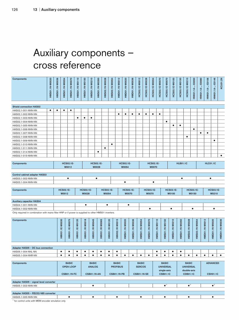
126 13 Auxiliary components
Auxiliary components –cross reference
Components BASIC OPEN LOOP
CSB01.1N-FC
BASIC ANALOG
CSB01.1N-AN
BASIC PROFIBUS
CSB01.1N-PB
BASIC SERCOS
CSB01.1N-SE
BASIC UNIVERSAL single-axisCSB01.1C
BASIC UNIVERSAL double-axisCDB01.1C
ADVANCED
CSH01.1C
Adapter HAS05 – signal level converter
HAS05.1-003-NNN-NN 1) 1) 1)
Adapter HAS05 – RS232/485 converter
HAS05.1-005-NNN-NN 1) for control units with MEM encoder emulation only
Components
HM
V01.
1E-W
0030
HM
V01.
1E-W
0075
HM
V01.
1E-W
0120
HM
V01.
1R-W
0018
HM
V01.
1R-W
0045
HM
V01.
1R-W
0065
HM
V01.
1R-W
0120
HM
V02.
1R-W
0015
HM
S01
.1N
-W00
20
HM
S01
.1N
-W00
36
HM
S01
.1N
-W00
54
HM
S01
.1N
-W00
70
HM
S01
.1N
-W01
10
HM
S01
.1N
-W01
50
HM
S01
.1N
-W02
10
HM
S01
.1N
-W03
50
HM
S02
.1N
-W00
28
HM
S02
.1N
-W00
54
HM
D01
.1N
-W00
12
HM
D01
.1N
-W00
20
HM
D01
.1N
-W00
36
Adapter HAS05 – DC bus connection
HAS05.1-004-NNL-NN
HAS05.1-004-NNR-NN
Components
HM
S01
.1N
-W00
20
HM
S01
.1N
-W00
36
HM
S01
.1N
-W00
54
HM
S01
.1N
-W00
70
HM
S01
.1N
-W01
10
HM
S01
.1N
-W01
50
HM
S01
.1N
-W02
10
HM
S01
.1N
-W03
50
HM
S02
.1N
-W00
28
HM
S02
.1N
-W00
54
HM
D01
.1N
-W00
12
HM
D01
.1N
-W00
20
HM
D01
.1N
-W00
36
HC
S02
.1E
-W00
12
HC
S02
.1E
-W00
28
HC
S02
.1E
-W00
54
HC
S02
.1E
-W00
70
HC
S03
.1E
-W00
70
HC
S03
.1E
-W01
00
HC
S03
.1E
-W01
50
HC
S03
.1E
-W02
10
HN
K01
.1A
-...-E
0050
HN
K01
.1A
-...-E
0080
HN
K01
.1A
-...-E
0106
HN
K01
.1A
-...-E
0146
KC
U01
.2N
Shield connection HAS02
HAS02.1-001-NNN-NN
HAS02.1-002-NNN-NN
HAS02.1-003-NNN-NN
HAS02.1-004-NNN-NN
HAS02.1-005-NNN-NN
HAS02.1-006-NNN-NN
HAS02.1-007-NNN-NN
HAS02.1-008-NNN-NN
HAS02.1-009-NNN-NN
HAS02.1-010-NNN-NN
HAS02.1-011-NNN-NN
HAS02.1-014-NNN-NN
HAS02.1-015-NNN-NN
Components HCS02.1E-W0012
HCS02.1E-W0028
HCS02.1E-W0054
HCS02.1E-W0070
HLB01.1C HLC01.1C
Control cabinet adapter HAS03
HAS03.1-002-NNN-NN
HAS03.1-004-NNN-NN
Components HCS02.1E-W0012
HCS02.1E-W0028
HCS02.1E-W0054
HCS02.1E-W0070
HCS03.1E-W0070
HCS03.1E-W0100
HCS03.1E-W0150
HCS03.1E-W0210
Auxiliary capacitor HAS04
HAS04.1-001-NNN-NN
HAS04.1-002-NNN-NN
Only required in combination with mains filter HNF or if power is supplied to other HMS01 inverters.
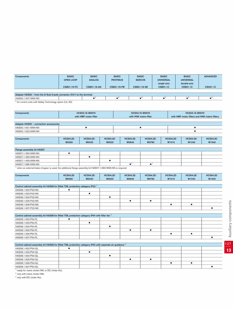
13127
Aux
iliar
y co
mpo
nent
s
Components HCS03.1E-W0070with HMF motor filter
HCS03.1E-W0070 with HNK mains filter
HCS03.1E-W0070 with HMF motor filters and HNK mains filters
Adapter HAS05 – connection accessories
HAS05.1-001-NNN-NN
HAS05.1-002-NNN-NN
Components HCS04.2E-W0350
HCS04.2E-W0420
HCS04.2E-W0520
HCS04.2E-W0640
HCS04.2E-W0790
HCS04.2E-W1010
HCS04.2E-W1240
HCS04.2E-W1540
Control cabinet assembly kit HAS08 for Rittal TS8, protection category IP23 1)
HAS08.1-002-P23-NN
HAS08.1-003-P23-NN
HAS08.1-004-P23-NN
HAS08.1-005-P23-NN
HAS08.1-006-P23-NN
HAS08.1-007-P23-NN
Control cabinet assembly kit HAS08 for Rittal TS8, protection category IP54 with filter fan 2)
HAS08.1-002-P54-FL
HAS08.1-003-P54-FL
HAS08.1-004-P54-FL
HAS08.1-005-P54-FL
HAS08.1-006-P54-FL
HAS08.1-007-P54-FL
Control cabinet assembly kit HAS08 for Rittal TS8, protection category IP54 with seperate air guidance 3)
HAS08.1-002-P54-GL
HAS08.1-003-P54-GL
HAS08.1-004-P54-GL
HAS08.1-005-P54-GL
HAS08.1-006-P54-GL
HAS08.1-007-P54-GL 1) ready for mains choke HNL or DC choke HLL2) only with mains choke HNL3) only with DC choke HLL
Components BASIC OPEN LOOP
CSB01.1N-FC
BASIC ANALOG
CSB01.1N-AN
BASIC PROFIBUS
CSB01.1N-PB
BASIC SERCOS
CSB01.1N-SE
BASIC UNIVERSAL single-axisCSB01.1C
BASIC UNIVERSAL double-axisCDB01.1C
ADVANCED
CSH01.1C
Adapter HAS05 – from the D-Sub 9-pole connector (X41) to the terminal
HAS05.1-007-NNN-NN 2) 2) 2) 2) 2) 2)
2) for control units with Safety Technology option (L2, S2)
Components HCS04.2E-W0350
HCS04.2E-W0420
HCS04.2E-W0520
HCS04.2E-W0640
HCS04.2E-W0790
HCS04.2E-W1010
HCS04.2E-W1240
HCS04.2E-W1540
Flange assembly kit HAS07
HAS07.1-350-NNN-NN
HAS07.1-330-NNN-NN
HAS07.1-430-NNN-NN
HAS07.1-585-NNN-NN 1) 1)
1) when an external brake chopper is used, the additional flange assembly kit HAS07.1-660-NNN-NN is required

128 13 Auxiliary components
Auxiliary components –connection cables
Motor Power unit Power cable Encoder cable
MSK030B-0900MSK030C-0900MSK040B-0450, -0600MSK040C-0450, -0600MSK050B-0300, -0450, -0600MSK050C-0300, -0450, -0600MSK060B-0300, -0600MSK060C-0300, -0600MSK061B-0300MSK061C-0200, -0300, -0600MSK076C-0300, -0450
HMD01.1N-W0012HMx01.1N-W0020HMx01.1N-W0036HCS02.1E-W0012HCS02.1E-W0028
RKL4302
RKG4200
HMS01.1N-W0054HMS01.1N-W0070HCS02.1E-W0054HCS02.1E-W0070HCS03.1E-W0070
RKL4303
MSK070C-0150, -0300, -0450MSK070D-0150MSK070E-0150MSK071C-0200, -0300, -0450MSK071D-0200, -0300, -0450MSK071E-0200, -0300MSK075C-0200, -0300, -0450MSK075D-0200, -0300MSK075E-0200, -0300
HMD01.1N-W0012HMx01.1N-W0020HMx01.1N-W0036HCS02.1E-W0012HCS02.1E-W0028
RKL4306
HMS01.1N-W0054HMS01.1N-W0070HCS02.1E-W0054HCS02.1E-W0070HCS03.1E-W0070
RKL4307
MSK070D-0300, -0450MSK070E-0300MSK071E-0450MSK075D-0450MSK075E-0450MSK103A-0300MSK103B-0300
HMx01.1N-W0020HMx01.1N-W0036HCS02.1E-W0012HCS02.1E-W0028
RKL4308
HMS01.1N-W0054HMS01.1N-W0070HCS02.1E-W0054HCS02.1E-W0070HCS03.1E-W0070
RKL4309
HMS01.1N-W0110HMS01.1N-W0150HMS01.1N-W0210HCS03.1E-W0100HCS03.1E-W0150
RKL4310
MSK070E-0450
HMS01.1N-W0054HMS01.1N-W0070HCS02.1E-W0054HCS02.1E-W0070HCS03.1E-W0070
RKL4314
HMS01.1N-W0110HMS01.1N-W0150HMS01.1N-W0210HCS03.1E-W0100HCS03.1E-W0150
RKL4315
MSK100A-0200, -0300, -0400MSK100B-0200MSK100D-0200MSK101C-0200
HMx01.1N-W0020HMx01.1N-W0036HCS02.1E-W0012HCS02.1E-W0028
RKL4325
HMS01.1N-W0054HMS01.1N-W0070HCS02.1E-W0054HCS02.1E-W0070HCS03.1E-W0070
RKL4320

13129
Aux
iliar
y co
mpo
nent
s
Motor Power unit Power cable Encoder cable
MSK100B-0300MSK100C-0200, -0300MSK100D-0300
HMx01.1N-W0020HMx01.1N-W0036HCS02.1E-W0012HCS02.1E-W0028
RKL4326
RKG4200
HMS01.1N-W0054HMS01.1N-W0070HCS02.1E-W0054HCS02.1E-W0070HCS03.1E-W0070
RKL4321
HMS01.1N-W0110HMS01.1N-W0150HMS01.1N-W0210HCS03.1E-W0100HCS03.1E-W0150
RKL4343
MSK100B-0400MSK100B-0450MSK101C-0300, -0450MSK103D-0300
HMx01.1N-W0020HMx01.1N-W0036HCS02.1E-W0012HCS02.1E-W0028HMS01.1N-W0054HMS01.1N-W0070HCS02.1E-W0054HCS02.1E-W0070HCS03.1E-W0070
RKL4327
RKL4322
MSK100C-0450MSK100D-0350MSK101D-0200, -0300MSK101E-0200MSK131B-0200MSK131D-0100
HMS01.1N-W0054HMS01.1N-W0070HCS02.1E-W0054HCS02.1E-W0070HCS03.1E-W0070
RKL4323
HMS01.1N-W0110HMS01.1N-W0150HMS01.1N-W0210HCS03.1E-W0100HCS03.1E-W0150
RKL4328
MSK101D-0450MSK101E-0300
HMS01.1N-W0054HMS01.1N-W0070HCS02.1E-W0054HCS02.1E-W0070HCS03.1E-W0070
RKL4324
HMS01.1N-W0110HMS01.1N-W0150HMS01.1N-W0210HCS03.1E-W0100HCS03.1E-W0150
RKL4329
MSK101E-0450
HMS01.1N-W0054HMS01.1N-W0070HCS02.1E-W0054HCS02.1E-W0070HCS03.1E-W0070
RKL4344
HMS01.1N-W0110HMS01.1N-W0150HMS01.1N-W0210HCS03.1E-W0100HCS03.1E-W0150
RKL4330
HCS03.1E-W0210 RKL4333
MSK131D-0200 HCS03.1E-W0210 RKL4349
These tables are an extract from our extensive range of cables. Cables for other motors can be found in our documentation entitled “Connection cables – selection data”.All specifications given relate to motors with natural convection.

130 14 Glossary
AB
C
D
E
I
F
Glossary
ADVANCED Control units for maximum performance anddynamics with many configuration options
BASIC Control units for standard applications
Basic accessories All the mounting parts and hardware, andthe connecting bars for the control voltageand DC bus
Brake chopperBrake transistor
Transistor which switches a brake resistoron and off
Braking power Power which is recovered in regenerativeoperation of the motors
Brake resistor For input power in regenerative operation(converted into heat)
Brake unit All-in-one unit comprising brake resistor andbraking transistor (brake chopper) used toincrease the braking power
Capacity module Optional auxiliary component to store energy in the DC bus
CLOSED LOOP Closed control loop (automatically regulatedoperation) in which the device being regulatedis monitored using a measuring system and made available to the drive
Control cabinet adapter
Spacer bolts used to even out differentunit depths
Control unit The part of the drive unit comprising all thecontrol functions and interfaces for installationin the power unit
Converter Takes the mains voltage with its fixed ampli- tude and frequency and generates a three- phase alternating current with variable ampli- tude and frequency
DC bus voltage DC voltage generated from the AC networkand used to supply the power units
Derating Lowering of the specified data in the eventof a change in operating conditions
Drive unit Converter and inverter consisting of a power and a contol unit, for the control of servo and standard motors.
EMC Electromagnetic compatibility
Encoder cable Cable used to connect the motor encoderto the encoder interface of the control unit
Firmware Device-specific software for the drivefunctions
Functions library Collection of function blocks conformingto IEC or PLCopen
IndraDrive C Compact drive series, converter
IndraDrive Cs Ultra-compact, multi-protocol-capable drive series, inverter
IndraDrive M Modular drive series, inverter and powersupply units
IndraDrive Mi Distributed drive series – Inverter, control unit and synchronous servo motor in one unit
IndraDyn A Air-cooled or liquid-cooled asynchronousservo motors
IndraDyn H High-speed frameless (kit) motors
IndraDyn L Synchronous linear motors
IndraDyn S Synchronous servo motors, also for potentially explosive areas
IndraDyn T Synchronous frameless (kit) torque motors

14131
Glo
ssar
y
OP
TU
M
S
IndraMotion MLD Integrated automation solution comprisingdrive functions, motion control and pro- cessing logic
IndraSize Software tool used for sizing and selectingdrives based on the machine data
IndraWorks Engineering framework toolkit for projectplanning, parameterization, start-up, diag-nostics, etc.
Inverter Takes the DC bus voltage and generates athree-phase alternating current with variableamplitude and frequency
Main choke Used to increase the continuous DC busoutput and to suppress harmonics
Main filter EMC filters for power supply units and converters used to reduce circuit feedback
Module bus Bus connection between power units forexchanging internal control signals
Module bus extension Optional bus connection used to bridgelarger than average distances between individ- ual drive control units
Motion logic Integrated automation solution comprisingdrive functions, motion control and processinglogic
Motor filter Used to protect the motor winding fromextreme voltage rises
OPEN LOOP Open control loop (controlled operation)in which the device being controlled is notmonitored using measuring techniques
Power cable Cable for connecting the motor to thepower unit
Power supply unit Takes the mains voltage with fixed amplitudeand frequency and generates a DCbus voltage
Power unit The part of the drive control unit containingthe power electronics to control the motors,used to hold the control unit
Safety on Board Safety technology integrated in the drive,certified as complying with EN 13849-1 Cat. 3 PL d and EN 62061 SIL 2
Shield connection Connection plate for EMC-compatible connec-tion of the motor cable to the control unit
Software module MultiMedia Card for simple transmission ofaxis-oriented drive parameters without theuse of a PC
Switching frequency Clock frequency of the pulse widthmodulation (PWM)
Technology package Process-oriented function blocks,e.g. tension control
User library Collection of function blocks developedby the user
User program Application-specific combination of differentfunction blocks / technology packages

132 15 Formulas
FormulasSpeed Torque Output Mass moment of inertia
Roller, wheel, pinionand belt drive
Ball screw drive
Pulley drive
Speed Torque Transmission ratio Mass moment of inertia
Gear conversion
n1 = n2 · i M1 =M2
ii =
n1
n2
J1 =J2
i2
n =v
2 · π · rM = m · g · r P =
m · g · v
60J = m · r2
n =v · 1000
hM =
F · h
2 · π · 1000P =
F · v
60J = m · h
2 · π · 1000 2
n =v
2 · r · πM = F · r P =
F · v
60J = m · r2
n1
J1
m
m
F, v
F, v
h
r
M, n
M, n
J2
M1
J1
M1M2
n2
n1
J2
M2
n2
mF, v
rM, n
M, n
m
vr
n1
J1
m
m
F, v
F, v
h
r
M, n
M, n
J2
M1
J1
M1M2
n2
n1
J2
M2
n2
mF, v
rM, n
M, n
m
vr
n1
J1
m
m
F, v
F, v
h
r
M, n
M, n
J2
M1
J1
M1M2
n2
n1
J2
M2
n2
mF, v
rM, n
M, n
m
vr
n1
J1
m
m
F, v
F, v
h
r
M, n
M, n
J2
M1
J1
M1M2
n2
n1
J2
M2
n2
mF, v
rM, n
M, n
m
vr

15133
Form
ulas
Unit conversion
Physical value Name of unit Conversion Name of unit
Force pound-force 1 lbf = 4.4482 N Newton
Power horsepower 1 hp = 745.7 W watt
Length inch 1 in = 25.4 mm millimeter
Length foot 1 ft = 0.3048 m meter
Mass pound 1 lb = 0.4536 kg kilogramm
Miscellaneous
Rotational frequency Effective electrical power
Rotational kinetic energy Apparent electrical power
Translational kinetic energy Reactive electrical power
Synchronous rpm DC bus voltage
Synchronous speed Force
=2 · π · n
60
W = · v2J
2
n =f · 60
p
v = 2 · f · τp
P = U · I · cosϕ · √3
S = U · I · √3
Q = U · I · sinϕ · √3
U = UNetz · √2
F = m · a
W = ·m
2
v
60 2
Legend
a – Acceleration [ms-2] J – Mass moment of inertia [kgm2] r – Radius [m]
F – Force [N] M – Torque [Nm] S – Apparent power [VA]
f – Frequency [s-1] m – Mass [kg] U – Voltage [V]
g – Gravitational acceleration [9,81 ms-2] n – Rotational speed [rpm] v – Speed [m/min]
h – Spindle pitch [mm] P – Power [W] W – Energy [Ws]
I – Current [A] p – Pole pair number τp – Pole pitch
i – Transmission ratio Q – Reactive power [var] – Rotational frequency [s-1]

134 16 Additional information
IndraDriveFirmwareTheory of operationR911328669/DER911328670/EN
Parameter descriptionR911297316/DER911297317/EN
IndraDriveControl UnitsProject PlanningManualR911295011/DER911295012/EN
IndraDrive MiConfigurationR911320925/DER911320924/EN
IndraMotion MLDLibrariesLibrary descriptionR911308317/DER911309224/EN
IndraMotion MLDThe first stepsBrief descriptionR911319304/DER911319306/EN
IndraLogicProgramminginstructionsR911305035/DER911305036/EN
TroubleshootinginformationR911297318/DER911297319/EN
IndraMotion MLDApplicationinstructionsR911306071/DER911306084/EN
Documentation and further informationDrive systemIndraDriveProject PlanningManualR911309635/DER911309636/EN
IndraDriveSupply Units andPower SectionsR911318789/DER911318790/EN
IndraDriveAdditionalcomponentsR911306139/DER911306140/EN
Safety technologyApplicationinstructionsR911297837/DER911297838/EN
IndraDrive Cs FirmwareApplication ManualR911326484/DER911326767/EN
Parameter descriptionR911328650/DER911328651/EN
IndraDrive HCS04Project Planning ManualR911327333/DER911327334/EN
IndraDrive Cs Project Planning Manual R911322209/DER911322210/EN
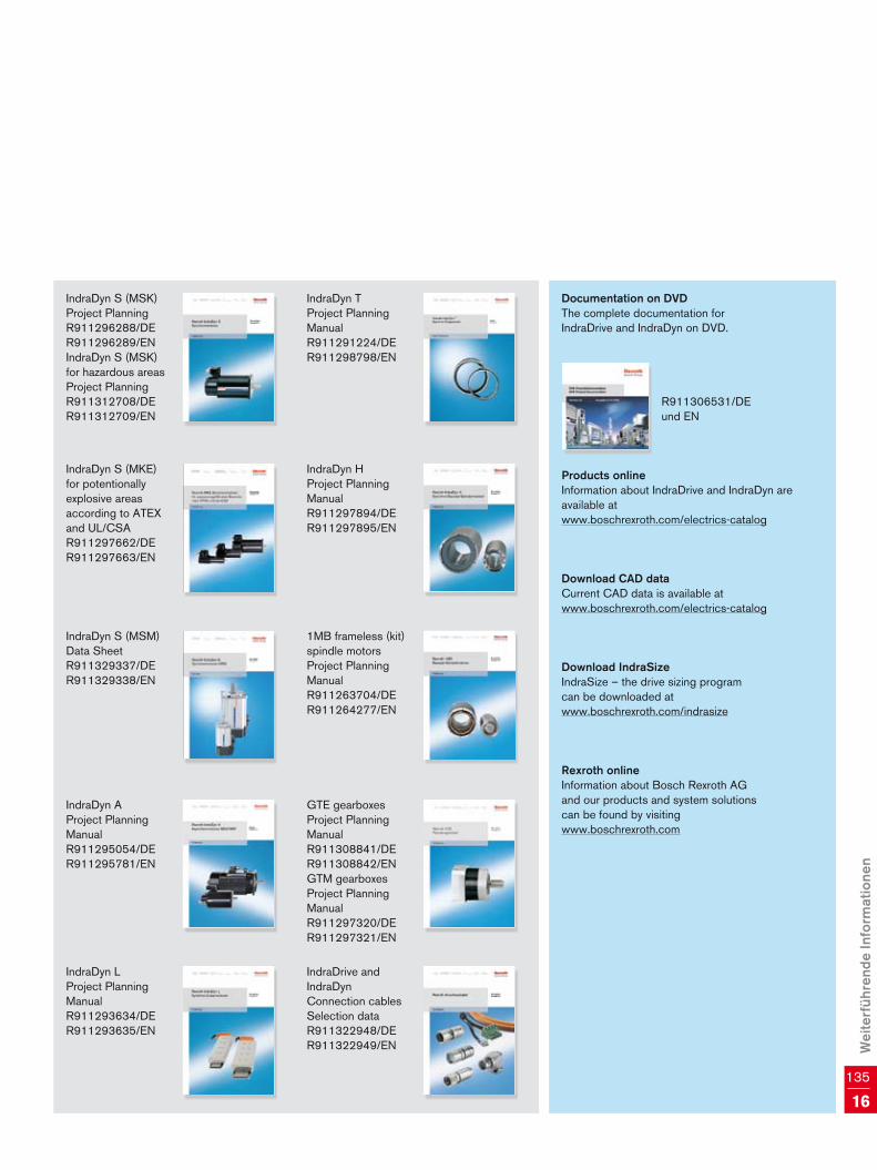
Wei
terf
ühre
nde
Info
rmat
ione
n
135
16
Documentation on DVDThe complete documentation forIndraDrive and IndraDyn on DVD.
R911306531/DE und EN
Products onlineInformation about IndraDrive and IndraDyn are available atwww.boschrexroth.com/electrics-catalog
Download CAD dataCurrent CAD data is available at www.boschrexroth.com/electrics-catalog
Download IndraSizeIndraSize – the drive sizing programcan be downloaded at www.boschrexroth.com/indrasize
Rexroth onlineInformation about Bosch Rexroth AGand our products and system solutionscan be found by visiting www.boschrexroth.com
IndraDyn LProject PlanningManualR911293634/DER911293635/EN
IndraDyn HProject PlanningManualR911297894/DER911297895/EN
IndraDyn TProject PlanningManualR911291224/DER911298798/EN
IndraDyn S (MSK) Project PlanningR911296288/DER911296289/ENIndraDyn S (MSK)for hazardous areasProject PlanningR911312708/DER911312709/EN
IndraDyn AProject PlanningManualR911295054/DER911295781/EN
GTE gearboxes Project PlanningManualR911308841/DER911308842/ENGTM gearboxesProject PlanningManualR911297320/DER911297321/EN
IndraDyn S (MSM)Data SheetR911329337/DER911329338/EN
IndraDrive andIndraDynConnection cablesSelection dataR911322948/DER911322949/EN
IndraDyn S (MKE)for potentionally explosive areas according to ATEX and UL/CSAR911297662/DER911297663/EN
1MB frameless (kit)spindle motorsProject PlanningManualR911263704/DER911264277/EN

Bosch Rexroth AGElectric Drives and ControlsP.O. Box 13 5797803 Lohr, GermanyBgm.-Dr.-Nebel-Str. 297816 Lohr, GermanyPhone +49 9352 40-0Fax +49 9352 40-4885www.boschrexroth.com/electrics
71 511 AE/2010-07-A6-HWR911313044© Bosch Rexroth AG 2010Subject to modification.Printed in Germany
The data specified above only serve to describe the product. As our products are constantly being further developed, no statements concerning a certain condition or suitability for a certain application can be derived from our infor-mation. The information given does not release the user from the obligation of own judgment and verification. It must be remembered that our products are subject to a natural process of wear and aging.
Presented by:


![[XLS] 1a... · Web viewSunita Mansharamani W/C/201007/1019 Dilip Mahumani W/C/201007/1020 Sanjiv Kumar W/C/201007/1021 Ratankumar Bhaskar Rao W/C/201007/1022 W/C/201007/1023 Gajanan](https://img.pdfslide.us/doc/110x75/5ad818297f8b9ab8378cebfb/xls-1aweb-viewsunita-mansharamani-wc2010071019-dilip-mahumani-wc2010071020.jpg)