Embed Size (px)
Citation preview

M I C R O T H E R M O T E C H N O L O G I E S ™
MT Alliance – RTU Plug-In Technician Manual
Document No. 71-MTA-1039-R1.1
No part of this publication may be reproduced, stored in a retrieval system, or transmitted, in any form or by any means, electronic, mechanical, photocopying, recording, or otherwise, without the prior written permission of Micro Thermo Technologies.
© 1997-2015 by Micro Thermo Technologies. All rights reserved worldwide.
Local Phone: (450) 668-3033 | Fax: (450)668-2695 Toll Free Canada: 1-888-664-1406 | Toll Free USA: 1-888-920-6284
www.sporlanonline.com/micro-thermo
71-MTA-1039-R1.1 RTU Plug-in Technician Manual.doc i
Table of Contents
HVAC MONITORING AND CONTROL ................................................. 1
1.1 INTRODUCTION ................................................................................................ 2 1.1.1 Dropping and Configuring the RTU Plug-in in MT Alliance ................. 3 1.1.2 RTU Plug-in Visibility in MT Alliance .................................................... 3 1.1.3 Associated Points in MT Alliance ........................................................... 4
1.2 RTU PLUG-IN OVERVIEW ................................................................................ 5 1.2.1 RTU Status and Current Values ............................................................. 5 1.2.2 Applying or Canceling Changes .............................................................. 6 1.2.3 RTU Configuration ................................................................................. 6
1.3 SYSTEM TAB ..................................................................................................... 7 1.3.1 Node Type ............................................................................................... 7 1.3.2 Humidity Mode ...................................................................................... 8 1.3.3 Occupancy Mode Group ........................................................................ 8 1.3.4 Status /Override Group .......................................................................... 9 1.3.5 Configuration Group ............................................................................... 9 1.3.6 Network Settings Group ....................................................................... 10
1.4 INPUTS TAB .................................................................................................... 11 1.4.1 Analog Inputs ........................................................................................ 11 1.4.2 Digital Inputs ........................................................................................ 13 1.4.3 Alarms Group ........................................................................................ 14
1.4.3.1 Analog inputs alarms ............................................................................................................ 14 1.4.3.2 Digital inputs alarms ............................................................................................................. 16
1.5 OUTPUTS TAB ................................................................................................. 17 1.5.1 Digital Outputs ...................................................................................... 17 1.5.2 Remote Preheat (1-3) ............................................................................ 18 1.5.3 Analog Outputs ..................................................................................... 18
1.6 SET POINTS TAB ............................................................................................ 20 1.6.1 Temperature Group ............................................................................. 20 1.6.2 Humidity Group ................................................................................... 22 1.6.3 Static Pressure Group ...........................................................................23 1.6.4 Winter/Summer Settings (OAT) Group ...............................................23 1.6.5 Outdoor / Indoor Status Group ............................................................23
1.7 SPACE TEMPERATURE SET POINT AUTO ADJUST ........................................... 24 1.7.1 Settings Group ..................................................................................... 24 1.7.2 Calculated Offset SP Group .................................................................. 25 1.7.3 Current Offset SP Group ....................................................................... 25 1.7.4 Offset Scale ............................................................................................ 25
1.8 FAN & DAMPER TAB ...................................................................................... 26 1.8.1 Fan Control Group ............................................................................... 26 1.8.2 Outside Air Damper (OAD) Group ...................................................... 28 1.8.3 Bypass Air Damper (BAD) Group (see annexe IV) ............................. 28
1.9 COOLING/HEATING TAB ............................................................................... 30 1.9.1 Cooling Control Group ......................................................................... 30
1.9.1.1 Cooling Stages ....................................................................................................................... 31
1.9.2 Preheat Control Group ......................................................................... 31 1.9.3 Heating (Secondary) Control Group ....................................................32 1.9.4 Modulating Heating Control Stg 1 Group (see Annexe II) ..................32
71-MTA-1039-R1.1 RTU Plug-in Technician Manual.doc ii
1.10 HUMIDITY TAB .......................................................................................... 34 1.10.1 Dehumidification Group ...................................................................... 34
1.11 LOG TAB .................................................................................................... 36
ANNEXE I - PROPORTIONAL AND PID CONFIGURATION PARAMETERS 37
ANNEXE II – MODULATING HEATING GROUP ...............................39
ANNEXE III – MONITORING THE RTU (SNVTS) ............................ 43
ANNEXE IV – RTU MECHANICAL & ELECTRICAL LAYOUT ........... 44
71-MTA-1039-R1.1 RTU Plug-in Technician Manual.doc 1
HVAC Monitoring and Control
Chapter
1

71-MTA-1039-R1.1 RTU Plug-in Technician Manual.doc 2
1.1 Introduction
Micro Thermo has a great deal of expertise in monitoring and controlling HVAC applications. After a hesitating beginning in 1995 (when only the MT2000 system existed at that time), the Alliance system helped a lot to acquire expertise with monitoring with data logging. At the beginning, starting with version 1.30, Alliance was used to control the HVAC in the supermarkets using third part controller (T&A, Siebe etc.). The field of applications was pretty restrained and the installer job was difficult due to the reduced flexibility of both the circuit (node) and its software. Also, the big number of configuration parameters, some of them codified created a lot of confusion and costly errors. When MT500 node series has been launched in 1999, Micro Thermo started to use them as HVAC controllers basically programmed with Visual Control. Alliance software was used to download the program in the controller, to adjust the configuration parameters, to change the set points and to monitor some interesting variables. Although the hardware and software flexibility has been increased, programming with Visual Control was highly problematic causing difficulties in installation, configuration, maintenance, training and job documentation. In a constant process of optimization of these costly operations, Micro Thermo’s R&D department has received the mandate to develop and implement a standardized solution able to cover many HVAC applications. Based on the percentage of the targeted market, the Rooftop Unit (RTU) has been chosen to be the first application to be implemented. This solution consisted in:
A RTU node profile that describe the LonMark objects, all associated network variables, the configuration parameters, alarm system description. A node software based on this profile able to cover many applications built around a RTU core. New version of the Alliance that shall support plug-ins (distinct pieces of software that can plug and communicate directly with the Alliance platform) A RTU plug-in used to configure, maintain, monitor and log all user actions. The plug-in will present the configuration information in an user-friendly format making a lot easier the installation and maintenance of this controller.
This manual has been conceived to help the technician to understand the capabilities of the RTU plug-in but requires knowledge of:
HVAC (mechanical and electrical architecture, functionality) Alliance (permissions, subsystems, navigation, connections, browsing network
variables) LonWorks (general information)

71-MTA-1039-R1.1 RTU Plug-in Technician Manual.doc 3
1.1.1 Dropping and Configuring the RTU Plug-in in MT Alliance
To install and configure a RTU controller in Alliance, the technician has to enter in the configuration mode for the HVAC subsystem. He has to drop a RTU custom node (in a HVAC view) and install it as described in the Alliance Technician Manual. He also must drop a plug-in, configure it as a MTPlugIn, select the Device scope and choose the RTU node just dropped before:
After the plug-in was completely configured, the Run Plug-In button allows the technician to start the plug-in.
1.1.2 RTU Plug-in Visibility in MT Alliance
The RTU plug-in is visible only in the maintenance and configuration modes being invisible for non-technical users like the store manager. In configuration mode the
71-MTA-1039-R1.1 RTU Plug-in Technician Manual.doc 4
access to the plug-in is provided only from the Run button in the plug-in information form but in maintenance mode it can be executed by simply clicking on the button representing the plug-in.
1.1.3 Associated Points in MT Alliance
To allow users with the appropriate permissions (Change Set Points in HVAC) to adjust the set points and to consult the historical data (graph and log) the technician will drop and configure custom points connected to the RTU node. After the plug-in configuration and accessing these points, they will become read only in Alliance excepting the set point adjustment.
71-MTA-1039-R1.1 RTU Plug-in Technician Manual.doc 5
1.2 RTU Plug-In Overview
1.2.1 RTU Status and Current Values
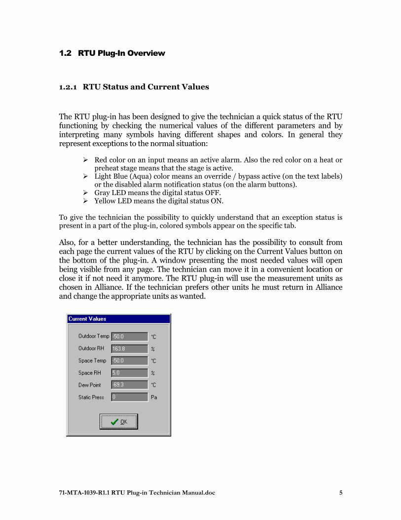
The RTU plug-in has been designed to give the technician a quick status of the RTU functioning by checking the numerical values of the different parameters and by interpreting many symbols having different shapes and colors. In general they represent exceptions to the normal situation:
Red color on an input means an active alarm. Also the red color on a heat or preheat stage means that the stage is active.
Light Blue (Aqua) color means an override / bypass active (on the text labels) or the disabled alarm notification status (on the alarm buttons).
Gray LED means the digital status OFF. Yellow LED means the digital status ON.
To give the technician the possibility to quickly understand that an exception status is present in a part of the plug-in, colored symbols appear on the specific tab. Also, for a better understanding, the technician has the possibility to consult from each page the current values of the RTU by clicking on the Current Values button on the bottom of the plug-in. A window presenting the most needed values will open being visible from any page. The technician can move it in a convenient location or close it if not need it anymore. The RTU plug-in will use the measurement units as chosen in Alliance. If the technician prefers other units he must return in Alliance and change the appropriate units as wanted.
71-MTA-1039-R1.1 RTU Plug-in Technician Manual.doc 6
1.2.2 Applying or Canceling Changes
If the technician make some changes it the RTU plug-in, the Apply and OK buttons will be enabled. By clicking on any of these buttons, a confirmation dialog will appear and a positive answer will save the plug-in changes, will log them and will try to send changes to the node.
Apply – clicking on this button a confirmation dialog will appear and a “Yes” answer will save the plug-in changes, will log them and will try to send changes to the node. If the technician answers “No”, the save operation will be aborted and no action will be taken.
OK - clicking on this button a confirmation dialog will appear and “Yes” answer will save the plug-in changes, will log them, will try to send changes to the node and will close the plug-in. If the technician answers “No”, the save operation will be aborted and no action will be taken but the plug-in will be closed. If he answers with “Cancel” the save operation will be aborted, no action will be taken but the plug-in will not be closed.
Cancel - clicking on this button a confirmation dialog will appear and “Yes” answer will discard the plug-in changes and will close the plug-in. If the technician answers “No” the cancel operation will be aborted, no action will be taken but the plug-in will not be closed.
1.2.3 RTU Configuration
Configuring the RTU means to select the appropriate inputs and outputs, choosing the right strategy, adjusting many parameters and sending them to the RTU node. It is very important that the technician make sure all parameters have been transmitted to the node (no error message occurred), otherwise the node may not function correctly. In the normal situation, after the technician made some changes and clicked on the Apply or OK button answering confirming the intention to keep the changes, only the modified parameters are sent to the node. In case of doubt, he may force sending of all parameters by selecting the Force Send CPs check box in the System tab.

71-MTA-1039-R1.1 RTU Plug-in Technician Manual.doc 7
1.3 System Tab
The RTU Plug-In has been designed to support RTU applications requiring a maximum of:
8 analog inputs (UI) 4 digital inputs (DI) 4 analog outputs (AO) 12 digital outputs (DO)
The node corresponding to the maximal number of I/O supported by the RTU PlugIn, is MT512.
1.3.1 Node Type
The controller (node) that can be used with this plug-in should be chosen depending on its I/O capabilities vs. the physical configuration of the rooftop unit (number of analog or digital sensors used, number of analog or digital stages, dampers etc.):
71-MTA-1039-R1.1 RTU Plug-in Technician Manual.doc 8
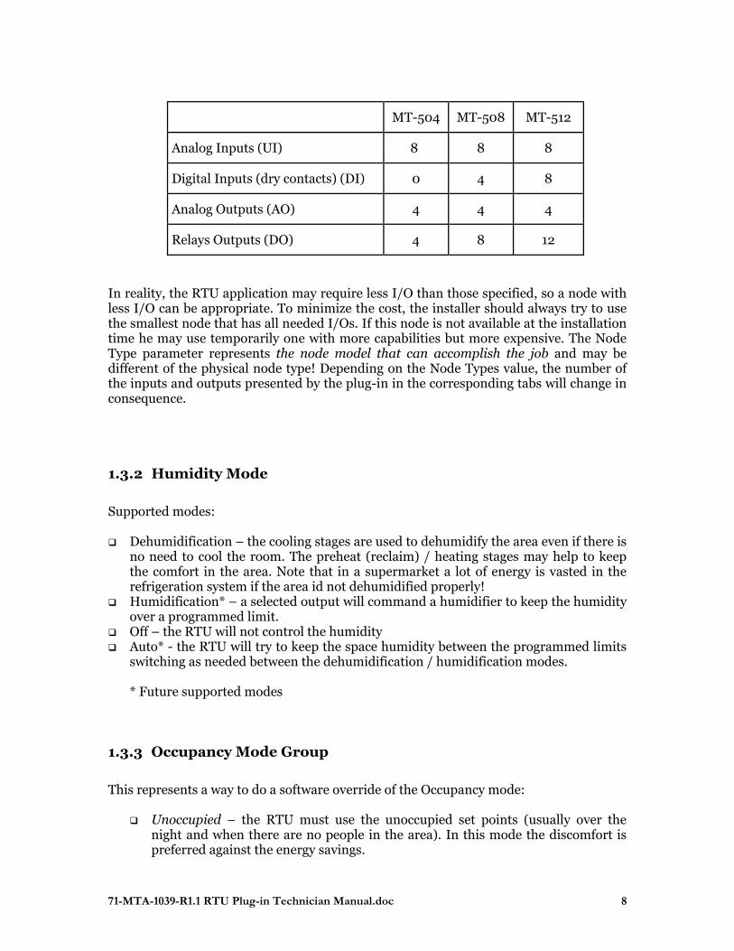
MT-504 MT-508 MT-512
Analog Inputs (UI) 8 8 8
Digital Inputs (dry contacts) (DI) 0 4 8
Analog Outputs (AO) 4 4 4
Relays Outputs (DO) 4 8 12
In reality, the RTU application may require less I/O than those specified, so a node with less I/O can be appropriate. To minimize the cost, the installer should always try to use the smallest node that has all needed I/Os. If this node is not available at the installation time he may use temporarily one with more capabilities but more expensive. The Node Type parameter represents the node model that can accomplish the job and may be different of the physical node type! Depending on the Node Types value, the number of the inputs and outputs presented by the plug-in in the corresponding tabs will change in consequence.
1.3.2 Humidity Mode
Supported modes: Dehumidification – the cooling stages are used to dehumidify the area even if there is
no need to cool the room. The preheat (reclaim) / heating stages may help to keep the comfort in the area. Note that in a supermarket a lot of energy is vasted in the refrigeration system if the area id not dehumidified properly!
Humidification* – a selected output will command a humidifier to keep the humidity over a programmed limit.
Off – the RTU will not control the humidity Auto* - the RTU will try to keep the space humidity between the programmed limits
switching as needed between the dehumidification / humidification modes.
* Future supported modes
1.3.3 Occupancy Mode Group
This represents a way to do a software override of the Occupancy mode:
Unoccupied – the RTU must use the unoccupied set points (usually over the night and when there are no people in the area). In this mode the discomfort is preferred against the energy savings.

71-MTA-1039-R1.1 RTU Plug-in Technician Manual.doc 9
Occupied – the RTU must use the occupied set points (usually during the day and when there are no people in the area). In this mode the comfort is preferred against the energy saving.
Auto – the RTU occupancy is not overridden. When this value is selected, the occupancy mode is determined in this order by a RTU node local sensor or by the value of the occupancy network variable of a HVAC scheduler bound to the RTU.
The current status of the RTU occupancy is shown in the Status item. More details about the occupied / unoccupied set points are given in the “Set Points” section of this document. The occupancy command can come from multiple sources having different priorities:
RTU Plug-in Occupancy Override (highest priority). Can be used remotely by modem.
Local Occupancy Switch (lowest priority) – if the digital input DI2 is configured and if its status is ON the unoccupied mode will be chosen. If the switch is opened, the occupancy mode will be determined by the HVAC Scheduler.
Scheduled Occupancy - the network variable nviOccCmd bound to a HVAC scheduler node.
Remote Occupancy - the network variable nviOccSensor bound to a remote node that reads an occupancy switch.
1.3.4 Status /Override Group
This group monitors the status of the RTU system presenting the current mode and the main parameters (cooling, preheat, heating) in percentages. In the RTU specifications, the technician has the possibility to set the system’s mode by an override value (this possibility is not implemented yet) to provide a way to test the sequencer that converts the analog output of a specific way (cooling, heating etc.) to a digital staged output.
1.3.5 Configuration Group
All parameters needed to program a RTU controller represent a configuration. Name – indicates the name of the current configuration or can be <Ad-hoc> if the plug-in was started from scratch and not by modifying an existing configuration. Plug-in Status – indicates the relation between the time stamp of the last save (indicated in parenthesis) of the plug-in vs. the time stamp of the configuration: If ConfigDateTime = PlugInDateTime: Status is 'SYNCHRONIZED' If ConfigDateTime < PlugInDateTime: Status is 'MODIFIED' If ConfigDateTime > PlugInDateTime: Status is 'OUT OF DATE'
71-MTA-1039-R1.1 RTU Plug-in Technician Manual.doc 10
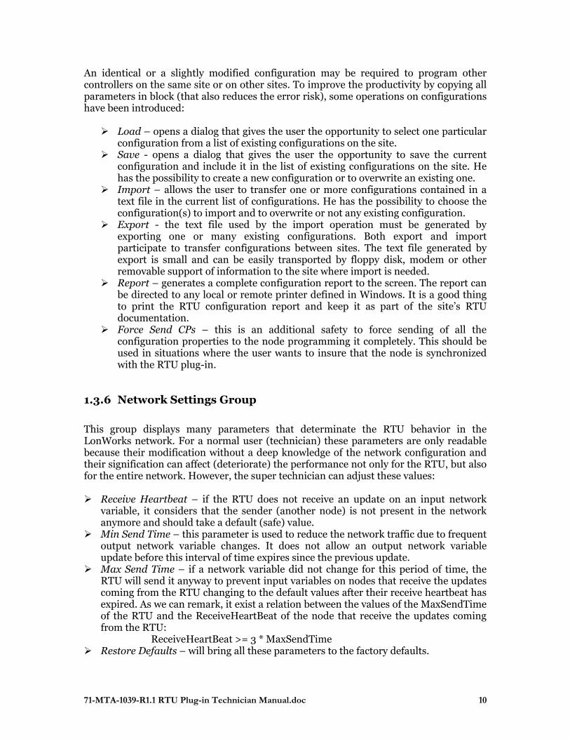
An identical or a slightly modified configuration may be required to program other controllers on the same site or on other sites. To improve the productivity by copying all parameters in block (that also reduces the error risk), some operations on configurations have been introduced: Load – opens a dialog that gives the user the opportunity to select one particular
configuration from a list of existing configurations on the site. Save - opens a dialog that gives the user the opportunity to save the current
configuration and include it in the list of existing configurations on the site. He has the possibility to create a new configuration or to overwrite an existing one.
Import – allows the user to transfer one or more configurations contained in a text file in the current list of configurations. He has the possibility to choose the configuration(s) to import and to overwrite or not any existing configuration.
Export - the text file used by the import operation must be generated by exporting one or many existing configurations. Both export and import participate to transfer configurations between sites. The text file generated by export is small and can be easily transported by floppy disk, modem or other removable support of information to the site where import is needed.
Report – generates a complete configuration report to the screen. The report can be directed to any local or remote printer defined in Windows. It is a good thing to print the RTU configuration report and keep it as part of the site’s RTU documentation.
Force Send CPs – this is an additional safety to force sending of all the configuration properties to the node programming it completely. This should be used in situations where the user wants to insure that the node is synchronized with the RTU plug-in.
1.3.6 Network Settings Group
This group displays many parameters that determinate the RTU behavior in the LonWorks network. For a normal user (technician) these parameters are only readable because their modification without a deep knowledge of the network configuration and their signification can affect (deteriorate) the performance not only for the RTU, but also for the entire network. However, the super technician can adjust these values: Receive Heartbeat – if the RTU does not receive an update on an input network
variable, it considers that the sender (another node) is not present in the network anymore and should take a default (safe) value.
Min Send Time – this parameter is used to reduce the network traffic due to frequent output network variable changes. It does not allow an output network variable update before this interval of time expires since the previous update.
Max Send Time – if a network variable did not change for this period of time, the RTU will send it anyway to prevent input variables on nodes that receive the updates coming from the RTU changing to the default values after their receive heartbeat has expired. As we can remark, it exist a relation between the values of the MaxSendTime of the RTU and the ReceiveHeartBeat of the node that receive the updates coming from the RTU:
ReceiveHeartBeat >= 3 * MaxSendTime Restore Defaults – will bring all these parameters to the factory defaults.
71-MTA-1039-R1.1 RTU Plug-in Technician Manual.doc 11
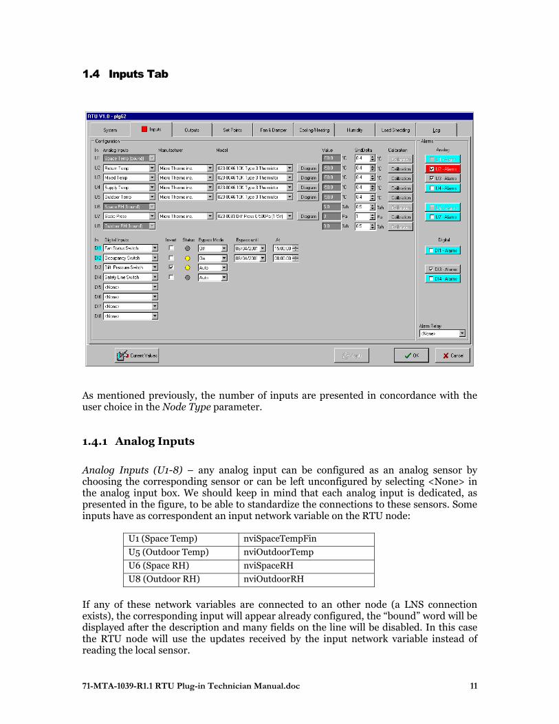
1.4 Inputs Tab
As mentioned previously, the number of inputs are presented in concordance with the user choice in the Node Type parameter.
1.4.1 Analog Inputs
Analog Inputs (U1-8) – any analog input can be configured as an analog sensor by choosing the corresponding sensor or can be left unconfigured by selecting <None> in the analog input box. We should keep in mind that each analog input is dedicated, as presented in the figure, to be able to standardize the connections to these sensors. Some inputs have as correspondent an input network variable on the RTU node:
U1 (Space Temp) nviSpaceTempFin
U5 (Outdoor Temp) nviOutdoorTemp
U6 (Space RH) nviSpaceRH
U8 (Outdoor RH) nviOutdoorRH
If any of these network variables are connected to an other node (a LNS connection exists), the corresponding input will appear already configured, the “bound” word will be displayed after the description and many fields on the line will be disabled. In this case the RTU node will use the updates received by the input network variable instead of reading the local sensor.
71-MTA-1039-R1.1 RTU Plug-in Technician Manual.doc 12
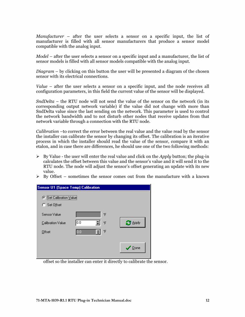
Manufacturer – after the user selects a sensor on a specific input, the list of manufacturer is filled with all sensor manufacturers that produce a sensor model compatible with the analog input. Model – after the user selects a sensor on a specific input and a manufacturer, the list of sensor models is filled with all sensor models compatible with the analog input. Diagram – by clicking on this button the user will be presented a diagram of the chosen sensor with its electrical connections. Value – after the user selects a sensor on a specific input, and the node receives all configuration parameters, in this field the current value of the sensor will be displayed. SndDelta – the RTU node will not send the value of the sensor on the network (in its corresponding output network variable) if the value did not change with more than SndDelta value since the last sending on the network. This parameter is used to control the network bandwidth and to not disturb other nodes that receive updates from that network variable through a connection with the RTU node. Calibration –to correct the error between the real value and the value read by the sensor the installer can calibrate the sensor by changing its offset. The calibration is an iterative process in which the installer should read the value of the sensor, compare it with an etalon, and in case there are differences, he should use one of the two following methods: By Value - the user will enter the real value and click on the Apply button; the plug-in
calculates the offset between this value and the sensor’s value and it will send it to the RTU node. The node will adjust the sensor’s offset generating an update with its new value.
By Offset – sometimes the sensor comes out from the manufacture with a known
offset so the installer can enter it directly to calibrate the sensor.
71-MTA-1039-R1.1 RTU Plug-in Technician Manual.doc 13
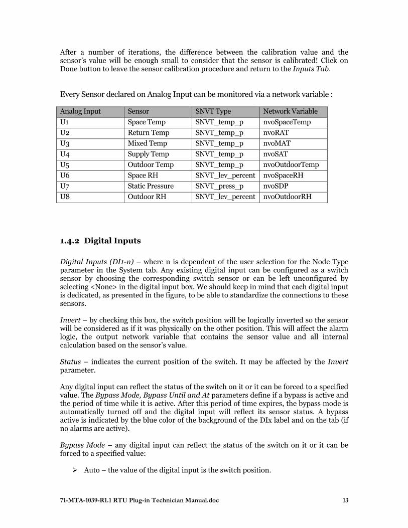
After a number of iterations, the difference between the calibration value and the sensor’s value will be enough small to consider that the sensor is calibrated! Click on Done button to leave the sensor calibration procedure and return to the Inputs Tab. Every Sensor declared on Analog Input can be monitored via a network variable :
Analog Input Sensor SNVT Type Network Variable
U1 Space Temp SNVT_temp_p nvoSpaceTemp
U2 Return Temp SNVT_temp_p nvoRAT
U3 Mixed Temp SNVT_temp_p nvoMAT
U4 Supply Temp SNVT_temp_p nvoSAT
U5 Outdoor Temp SNVT_temp_p nvoOutdoorTemp
U6 Space RH SNVT_lev_percent nvoSpaceRH
U7 Static Pressure SNVT_press_p nvoSDP
U8 Outdoor RH SNVT_lev_percent nvoOutdoorRH
1.4.2 Digital Inputs
Digital Inputs (DI1-n) – where n is dependent of the user selection for the Node Type parameter in the System tab. Any existing digital input can be configured as a switch sensor by choosing the corresponding switch sensor or can be left unconfigured by selecting <None> in the digital input box. We should keep in mind that each digital input is dedicated, as presented in the figure, to be able to standardize the connections to these sensors. Invert – by checking this box, the switch position will be logically inverted so the sensor will be considered as if it was physically on the other position. This will affect the alarm logic, the output network variable that contains the sensor value and all internal calculation based on the sensor’s value. Status – indicates the current position of the switch. It may be affected by the Invert parameter. Any digital input can reflect the status of the switch on it or it can be forced to a specified value. The Bypass Mode, Bypass Until and At parameters define if a bypass is active and the period of time while it is active. After this period of time expires, the bypass mode is automatically turned off and the digital input will reflect its sensor status. A bypass active is indicated by the blue color of the background of the DIx label and on the tab (if no alarms are active). Bypass Mode – any digital input can reflect the status of the switch on it or it can be forced to a specified value: Auto – the value of the digital input is the switch position.
71-MTA-1039-R1.1 RTU Plug-in Technician Manual.doc 14
On – the digital input value is forced to ON Off - the digital input value is forced to OFF
Bypass Until – specifies the date until the bypass is effective. At – specifies the time until the bypass is effective. If the node type is MT504, it does not have any digital input. Because the “Fan Status Switch” is a very important input parameter for the RTU and because there are no digital inputs, the analog input U8 has been programmed to accept a switch sensor to be able to connect it! Every Sensor declared on Digital Input can be monitored via network variable SNVT_state nvoDIState :
Digital Input Sensor Network Variable D1 Fan Status Switch nvoDIState.bit0 D2 Occupancy Switch nvoDIState.bit1 D3 Diff. Pressure Switch nvoDIState.bit2
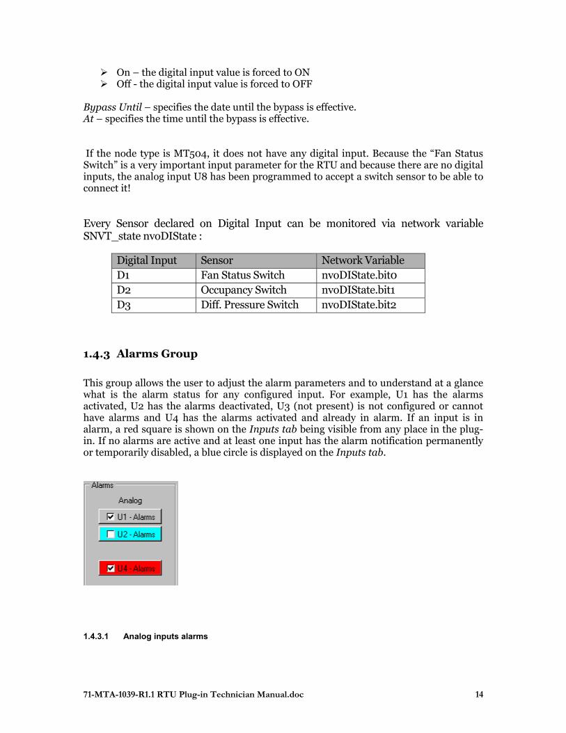
1.4.3 Alarms Group
This group allows the user to adjust the alarm parameters and to understand at a glance what is the alarm status for any configured input. For example, U1 has the alarms activated, U2 has the alarms deactivated, U3 (not present) is not configured or cannot have alarms and U4 has the alarms activated and already in alarm. If an input is in alarm, a red square is shown on the Inputs tab being visible from any place in the plug-in. If no alarms are active and at least one input has the alarm notification permanently or temporarily disabled, a blue circle is displayed on the Inputs tab.
1.4.3.1 Analog inputs alarms
71-MTA-1039-R1.1 RTU Plug-in Technician Manual.doc 15
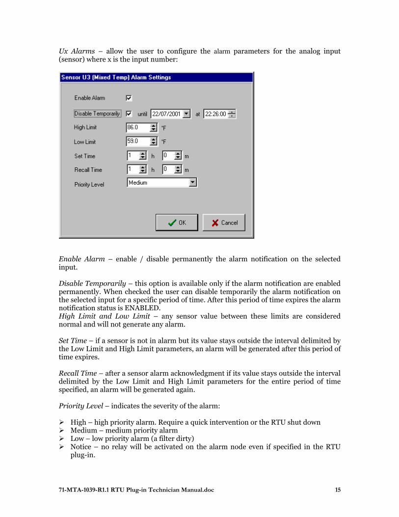
Ux Alarms – allow the user to configure the alarm parameters for the analog input (sensor) where x is the input number:
Enable Alarm – enable / disable permanently the alarm notification on the selected input. Disable Temporarily – this option is available only if the alarm notification are enabled permanently. When checked the user can disable temporarily the alarm notification on the selected input for a specific period of time. After this period of time expires the alarm notification status is ENABLED. High Limit and Low Limit – any sensor value between these limits are considered normal and will not generate any alarm. Set Time – if a sensor is not in alarm but its value stays outside the interval delimited by the Low Limit and High Limit parameters, an alarm will be generated after this period of time expires. Recall Time – after a sensor alarm acknowledgment if its value stays outside the interval delimited by the Low Limit and High Limit parameters for the entire period of time specified, an alarm will be generated again. Priority Level – indicates the severity of the alarm: High – high priority alarm. Require a quick intervention or the RTU shut down Medium – medium priority alarm Low – low priority alarm (a filter dirty) Notice – no relay will be activated on the alarm node even if specified in the RTU
plug-in.
71-MTA-1039-R1.1 RTU Plug-in Technician Manual.doc 16
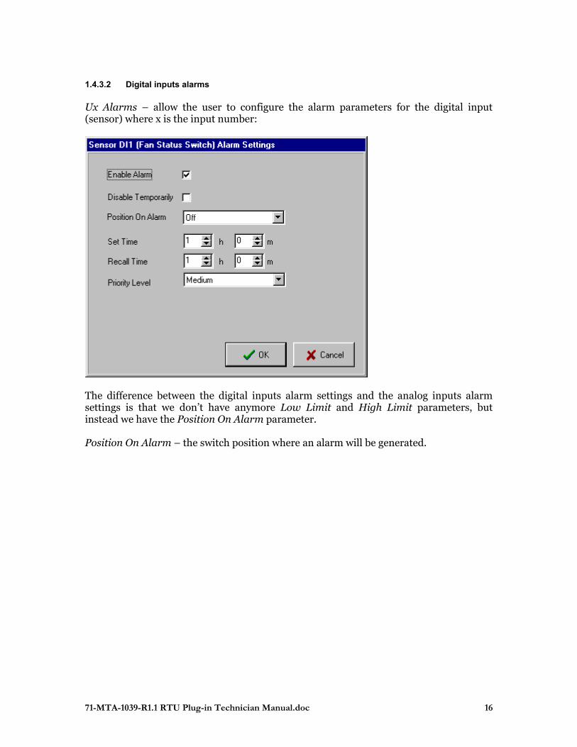
1.4.3.2 Digital inputs alarms Ux Alarms – allow the user to configure the alarm parameters for the digital input (sensor) where x is the input number:
The difference between the digital inputs alarm settings and the analog inputs alarm settings is that we don’t have anymore Low Limit and High Limit parameters, but instead we have the Position On Alarm parameter. Position On Alarm – the switch position where an alarm will be generated.
71-MTA-1039-R1.1 RTU Plug-in Technician Manual.doc 17
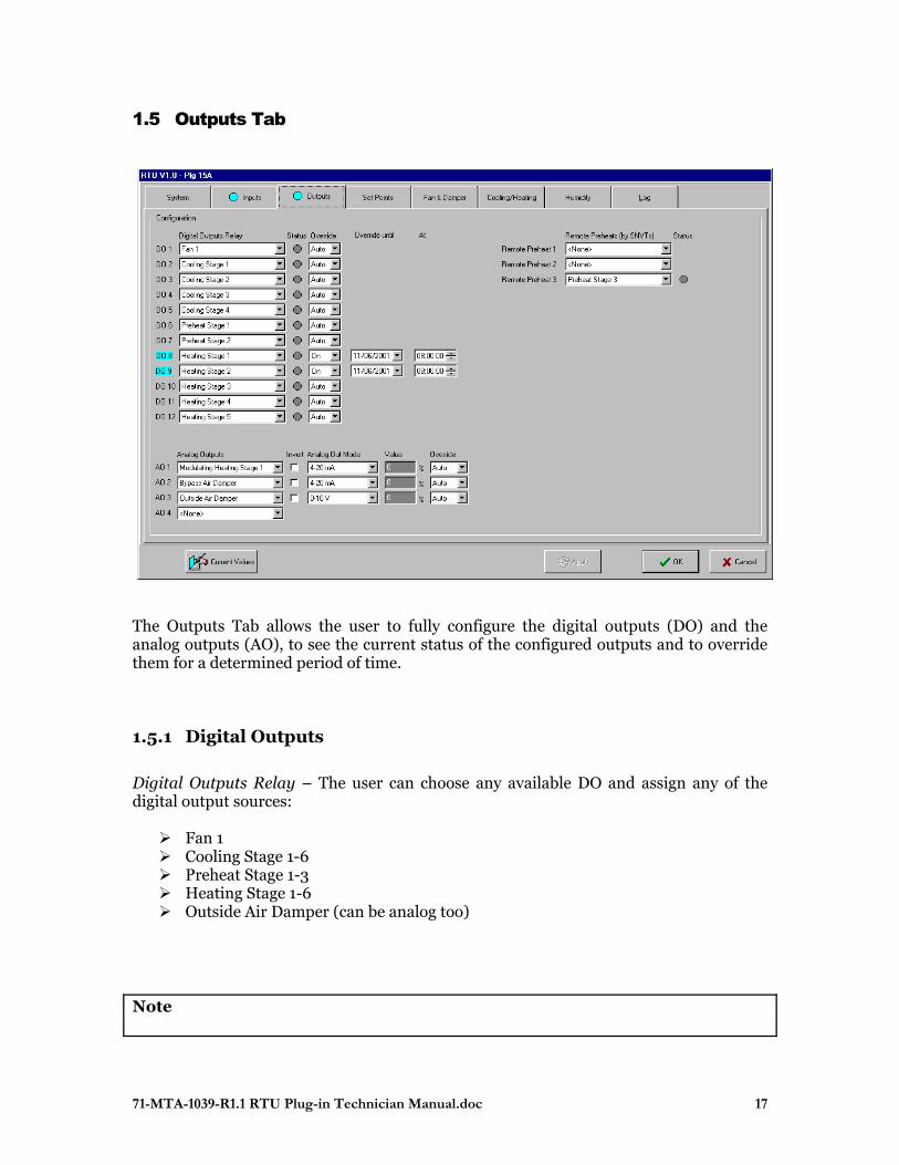
1.5 Outputs Tab
The Outputs Tab allows the user to fully configure the digital outputs (DO) and the analog outputs (AO), to see the current status of the configured outputs and to override them for a determined period of time.
1.5.1 Digital Outputs
Digital Outputs Relay – The user can choose any available DO and assign any of the digital output sources: Fan 1 Cooling Stage 1-6 Preheat Stage 1-3 Heating Stage 1-6 Outside Air Damper (can be analog too)
Note
71-MTA-1039-R1.1 RTU Plug-in Technician Manual.doc 18
The RTU plug-in DOs and AOs respect the rule that a stage having a superior index is not available for configuration if all other stages having inferior indexes are not configured! DO Status - after the RTU node has received the configuration parameters, the status of the outputs is presented:
Yellow ( ) – the relay is ON (energized) Gray ( ) – the relay is OFF (not energized)
Any digital output can be overridden for a determined period of time: the relay status will be determined by the override value and not by the RTU strategy. Override – specifies the override mode and the override value:
Auto - the DO is controlled by the strategy (no override). On – the DO is forced to ON for the period of time specified by the Until and
At parameters Off – the DO is forced to OFF for the period of time specified by the Until and
At parameters If an override is applied (sent to the RTU node) the DOi label is colored in blue and a blue circle is shown on the Outputs tab. NOTE In some situations, there are protections in the strategy that prevents an override to be effective! For more details, please refer to the strategy manual.
1.5.2 Remote Preheat (1-3)
Are used to control the relays on another node: the RTU determines the need to use the heat generated in the refrigeration subsystem, but the preheat valves are already controlled by a refrigeration node. In this case the technician has to connect manually (in Alliance) the RTU’s network variables nvoRemPreheati with the correspondent input variable on the SPC node. The Status LEDs will indicate the current status of the configured remote preheats.
1.5.3 Analog Outputs
Similarly, the technician can choose any available AO and assign it any of the analog output sources:
Modulated Heating Stage 1 Outside Air Damper Bypass Air Damper
71-MTA-1039-R1.1 RTU Plug-in Technician Manual.doc 19
Analog Out Mode – is used to configure any analog output selecting a voltage output or a current output and its range. There are presented only supported standard output modes:
4 – 20 mA (0% - 100% PID) 0 - 5 V 0 – 10 V 2 – 10V
Invert – if inverted the physical output range will be reversed:
20 – 4 mA (0% - 100% PID) 5 - 0 V 10 – 0 V 10 – 2 V
Status – presents in percentage the corresponding PID output value. Override – shows the override mode:
Auto – the analog output is controlled by the strategy (PID) Manual – the corresponding PID output is forced to a selected override value.
Overd Value – the value in percent that will replace the PID output if an override is active. Override Until and At – delimits the period of time for an override to be active. After this period of time expires the override is automatically removed and the corresponding PID will control the analog output. If an override is applied (sent to the RTU node) the AOi label is colored in blue and a blue circle is shown on the Outputs tab.
71-MTA-1039-R1.1 RTU Plug-in Technician Manual.doc 20
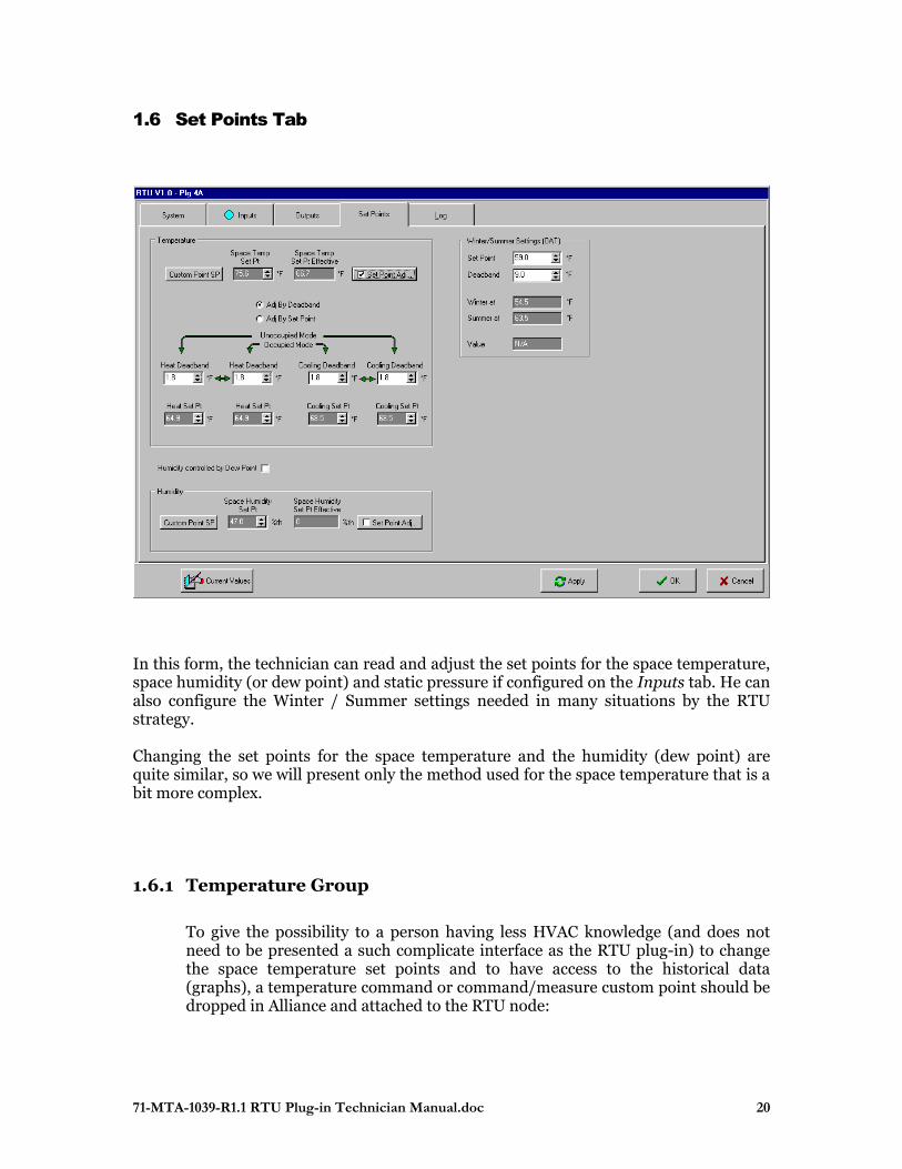
1.6 Set Points Tab
In this form, the technician can read and adjust the set points for the space temperature, space humidity (or dew point) and static pressure if configured on the Inputs tab. He can also configure the Winter / Summer settings needed in many situations by the RTU strategy. Changing the set points for the space temperature and the humidity (dew point) are quite similar, so we will present only the method used for the space temperature that is a bit more complex.
1.6.1 Temperature Group
To give the possibility to a person having less HVAC knowledge (and does not need to be presented a such complicate interface as the RTU plug-in) to change the space temperature set points and to have access to the historical data (graphs), a temperature command or command/measure custom point should be dropped in Alliance and attached to the RTU node:
71-MTA-1039-R1.1 RTU Plug-in Technician Manual.doc 21
The node that should be selected in the command node box is your RTU node
The input network variable name that should be selected in the command box is nviSetPoint.
If you dropped a command/measure custom point:
The node that should be selected in the measure node box is your RTU node
The output network variable name that should be selected in the command box is nvoSpaceTemp.
Custom Points SP – the technician has a way to directly access from the plug-in the custom points associated to the set points to consult the historical graph and log or to change the set points. Once these custom points are accessed by the RTU plug-in they become read-only so they will be maintained / deleted only by a technician (has the right to configure the HVAC) coming only from the RTU plug-in! However a person having the permission to change the HVAC set points will be able to change them from Alliance even in the overview mode. Set Point Adj – provide access to a window (see Space Temperature Set Point Auto Adjust section at the end of this chapter) where the installer can specify an offset adjustment curve for the set point in function of the outdoor temperature. This is useful when the place where the space temperature sensor can be affected by the outdoor temperature and need to be compensated. Ex: in a supermarket the cash are located at the exit so the air entering in the store can affect the reading of the space temperature.
Space Temp Effective Set Pt - the set point (adjusted or not) is displayed in this box and may be monitored on network variable nvoEffectSetPt.
After determining the effective (global) set point, the technician has to configure the relative cooling, preheat and heating set points or dead bands for both occupied and unoccupied modes.
The relative set points are :
Unocc Heat Set Pt Set point for Heating Group in Unoccupied mode Occ Heat Set Pt Set point for Heating Group in Occupied mode Occ Cooling Set Pt Set point for Cooling Group in Occupied mode Unocc Cooling Set Pt Set point for Cooling Group in Unoccupied mode
These set points will determine the On and Off trip points for the Cooling, Preheating and Heating stages as described further in the Cooling / Heating tab.
He has two methods and should choose the one he is most familiar with:
71-MTA-1039-R1.1 RTU Plug-in Technician Manual.doc 22
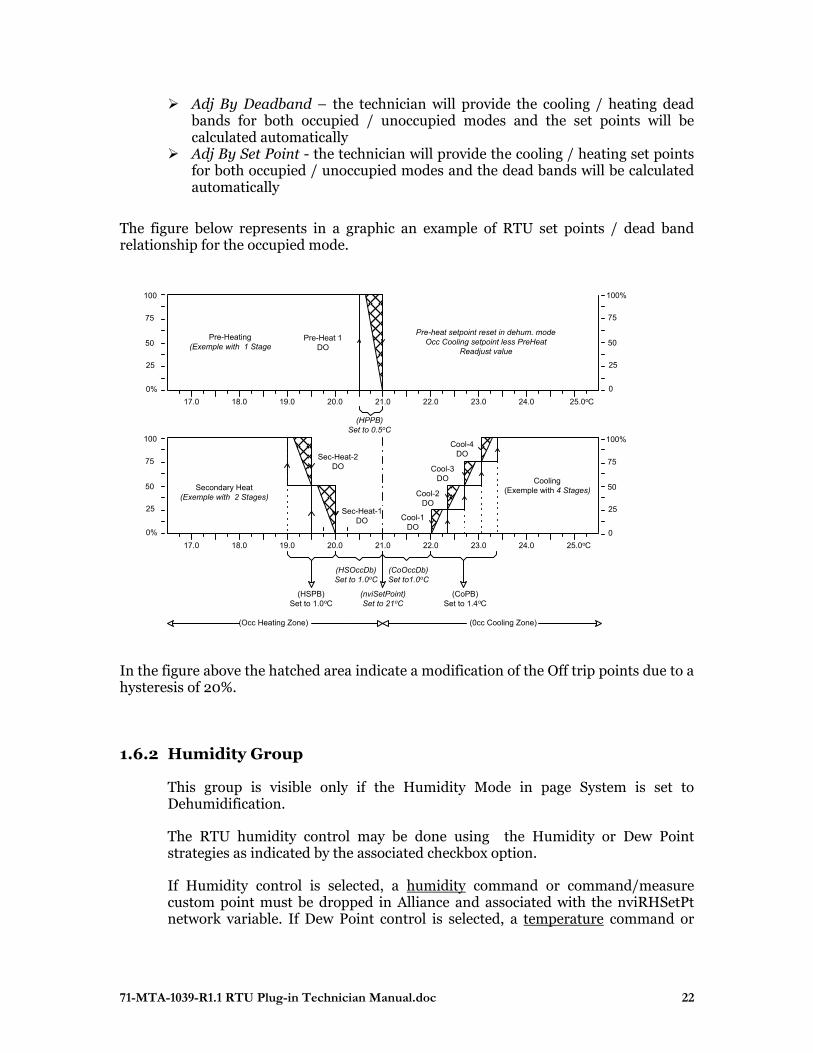
Adj By Deadband – the technician will provide the cooling / heating dead bands for both occupied / unoccupied modes and the set points will be calculated automatically
Adj By Set Point - the technician will provide the cooling / heating set points for both occupied / unoccupied modes and the dead bands will be calculated automatically
The figure below represents in a graphic an example of RTU set points / dead band relationship for the occupied mode.
In the figure above the hatched area indicate a modification of the Off trip points due to a hysteresis of 20%.
1.6.2 Humidity Group
This group is visible only if the Humidity Mode in page System is set to Dehumidification.
The RTU humidity control may be done using the Humidity or Dew Point strategies as indicated by the associated checkbox option.
If Humidity control is selected, a humidity command or command/measure custom point must be dropped in Alliance and associated with the nviRHSetPt network variable. If Dew Point control is selected, a temperature command or
25
50
75
100
0%
25
50
75
100%
0
25
50
75
100
0%
25
50
75
100%
0
21.0 22.0 23.0 24.0 25.0oC20.019.018.017.0
Sec-Heat-1DO Cool-1
DO
Cool-2DO
Cool-3DO
Cool-4DO
Pre-Heat 1DO
Pre-Heating(Exemple with 1 Stage
Secondary Heat(Exemple with 2 Stages)
Cooling(Exemple with 4 Stages)
(CoPB)Set to 1.4oC
(HSOccDb)Set to 1.0oC
(CoOccDb)Set to1.0oC
(Occ Heating Zone) (0cc Cooling Zone)
(nviSetPoint)Set to 21oC
(HSPB)Set to 1.0oC
Pre-heat setpoint reset in dehum. modeOcc Cooling setpoint less PreHeat
Readjust value
(HPPB)Set to 0.5oC
21.0 22.0 23.0 24.0 25.0oC20.019.018.017.0
Sec-Heat-2DO
71-MTA-1039-R1.1 RTU Plug-in Technician Manual.doc 23
command/measure custom point must be dropped in Alliance and associated with the nviDewPtSetPt network variable.
The set point can be changed from the RTU plug-in by pushing the Custom Point SP button. Also it can be accessed and modified from Alliance by any user that has change HVAC set points permission.
The Humidity or Dew Point Set Point can be modulated by the Outdoor Temp if desired by pushing the Set Point Adj button to enable this option and configure it as wanted by establishing a linear relation between Outdoor Temp and Humidity or Dew Point Set Point. The resulting set point (adjusted or not) is displayed in the Space Humidity or Dew Point Effective Set Pt box and may be monitored on network variable nvoRHSetPt or nvoDewPtSetPt.
1.6.3 Static Pressure Group
This group is visible only if the Static Pressure sensor has been selected on the U7 input on the Inputs tab. The static pressure control is used in the Variable Air Volume system to control the Supply Air Pressure (see annexe IV).
Static Press Set Pt - set point can be adjusted only by the technician from the RTU plug-in.
Static Pressure – presents the current value of the static pressure.
1.6.4 Winter/Summer Settings (OAT) Group
This section is used to configure the temperature set point and deadband that will determine if the system is in summer or in winter state. Based on those values the trip points Winter at and Summer at are displayed in their associated box and the current state is displayed in the Value box.
The current Winter/Summer state would be used by any Control Group where this option is enabled. For example, if Cooling Group has its Winter/Enable option enabled the cooling stages will be available only if current mode is Summer.
1.6.5 Outdoor / Indoor Status Group
This group contain useful information coming from RTU’s output network variables that give actual values for :
Outdoor Temp Outdoor RH Space Temp
71-MTA-1039-R1.1 RTU Plug-in Technician Manual.doc 24
Space RH Dew Point
1.7 Space Temperature Set Point Auto Adjust
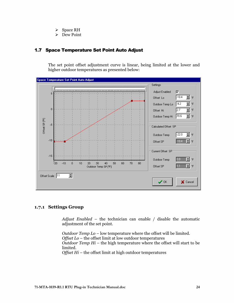
The set point offset adjustment curve is linear, being limited at the lower and higher outdoor temperatures as presented below:
1.7.1 Settings Group
Adjust Enabled – the technician can enable / disable the automatic adjustment of the set point. Outdoor Temp Lo – low temperature where the offset will be limited. Offset Lo – the offset limit at low outdoor temperatures Outdoor Temp Hi – the high temperature where the offset will start to be limited. Offset Hi – the offset limit at high outdoor temperatures
71-MTA-1039-R1.1 RTU Plug-in Technician Manual.doc 25
1.7.2 Calculated Offset SP Group
It is a tool that helps the technician to simulate an outdoor temperature Outdoor Temp and see what it will be the Offset SP adjustment. He can change the value of the simulated outdoor temperature and also he can move the cursor on the top of graph simulating the outdoor temp change.
1.7.3 Current Offset SP Group
The technician can see the current outdoor temperature Outdoor Temp and the current Offset SP .
1.7.4 Offset Scale
The technician can see the adjustment curve with different vertical zoom factors. By default when this form is displayed, the graph Y (offset) axis is adjusted automatically to fit in the graph. Sometimes the technician wants to have access to a bigger range of offsets and this is possible by increasing the Offset Scale. This is a visual parameter for the plug-in and it does not affect the RTU node.
71-MTA-1039-R1.1 RTU Plug-in Technician Manual.doc 26
1.8 Fan & Damper Tab
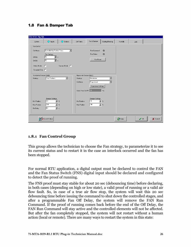
1.8.1 Fan Control Group
This group allows the technician to choose the Fan strategy, to parameterize it to see its current status and to restart it in the case an interlock occurred and the fan has been stopped.
For normal RTU application, a digital output must be declared to control the FAN and the Fan Status Switch (FNS) digital input should be declared and configured to detect the proof of running.
The FNS proof must stay stable for about 20 sec (debouncing time) before declaring, in both cases (depending on high or low state), a valid proof of running or a valid air flow fault. So, in case of a true air flow stop, the system will wait this 20 sec debouncing time before issuing the command to shut down the controlled stages, and after a programmable Fan Off Delay, the system will remove the FAN Run Command. If the proof of running comes back before the end of the Off Delay, the FAN Run Command will stay active and the controlled elements will not be affected. But after the fan completely stopped, the system will not restart without a human action (local or remote). There are many ways to restart the system in this state:

71-MTA-1039-R1.1 RTU Plug-in Technician Manual.doc 27
As soon as the controller detect an air flow proof, real or simulated, the RTU Start Cycle will be reinitiated and the FAN Run Command Relay will turn ON after the programmable OnDelay. This can be done in different ways:
Fan Reset button
Timed override on FNS input in the Inputs page.
In the Alliance the node can be reset accessing the dropped custom node.
On site a hardware reset can be done directly on the controller board or put a jumper between FNS input and SGND momentarily until the system comes alive again with a good air flow proof.
By a manual Fan command to restart the FAN until a stable air flow is established and a stable air flow proof is detected, the system can then be returned to Auto.
Ctrl Mode – determines the fan strategy:
Auto – the fan will be ON only when a request for cooling
(dehumidification) or heating is present. OFF - the fan is turned OFF shutting down the whole RTU. Continuous – the fan is always ON. Occ Continuous / UnOcc Auto – the fan is in mode Continuous in
occupied mode and Auto in the unoccupied mode. Controlled by Outdoor Temp – the fan is controlled by the
combinations between the next three parameters:
Winter Mode checked – the fan runs in Winter mode Summer Mode checked – the fan runs in Summer mode Occupied Only – the fan will run in occupied mode but not in
unoccupied mode If both Winter Mode and Summer Mode are checked – the fan runs independently of the Winter/Summer Mode.
Off Delay – if the strategy issues a fan stop command for all the period of time specified by this parameter, the fan will be turned OFF and otherwise it will stay ON. This delay is useful to reduce cycling.
71-MTA-1039-R1.1 RTU Plug-in Technician Manual.doc 28
On Delay – the fan will wait after the strategy issues a fan start command for all the period of time specified by this parameter before to effectively start. This delay is useful to avoid an energy peak by distributing the start of the RTUs in case of a simultaneous power up (after a power failure). It is important that the installer choose different On Delay for each RTU. Fan Reset - in the eventuality that an interlock occurs and the fan stops, the technician can use this button (that acts like a breaker) to restart the fan and the RTU. This facility can be used locally or with caution remotely (by modem).
1.8.2 Outside Air Damper (OAD) Group
This group visible only if the Outside Air Damper has been configured on a digital or analog output, allows the technician to choose the OAD strategy and to parameterize it. Ctrl Mode – determines the fan strategy:
Built-in Economizer – the OAD damper is not controlled by the RTU strategy but by an built-in economizer.
Two Positions – if the OAD is configured on a digital output, it will be closed in unoccupied mode and opened in the occupied mode. If the OAD is configured on an analog output, it will be closed in the unoccupied mode but opened to a programmable minimum position value. If a command Exhaust Fan has been received on the nviExhFanSignal network variable, the OAD will opened to its programmable maximum position.
Min Position – minimum position of the damper (%)
Max Position – maximum position of the damper (%) On Delay – the OAD damper position will not change if the command is not stable for this interval of time.
1.8.3 Bypass Air Damper (BAD) Group (see annexe IV)
This group visible only if the Bypass Air Damper has been configured on an analog output allows the technician to choose the BAD strategy and parameterize it.
The BAD control uses its own PID block configured to control the opening of the damper to maintain the Supply Air Pressure to its setpoint. The minimum and maximum opening positions are programmable to limit the travel of the damper.
71-MTA-1039-R1.1 RTU Plug-in Technician Manual.doc 29
Strategy – only Modulation strategy is supported. Ctrl Mode – determines the fan strategy:
PID Proportional
PID / Proportional Settings – this button give access to the corresponding PID / Proportional block of parameters (see annexe I) Static Press Set Pt – repeats the Static Pressure set point as defined in the Set Points tab
Min Position – minimum position of the damper (%)
Max Position – maximum position of the damper (%) On Delay – the OAD damper position will not change if the command is not stable for this interval of time.
71-MTA-1039-R1.1 RTU Plug-in Technician Manual.doc 30
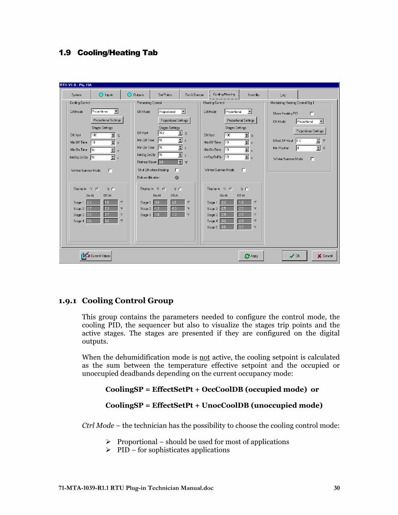
1.9 Cooling/Heating Tab
1.9.1 Cooling Control Group
This group contains the parameters needed to configure the control mode, the cooling PID, the sequencer but also to visualize the stages trip points and the active stages. The stages are presented if they are configured on the digital outputs.
When the dehumidification mode is not active, the cooling setpoint is calculated as the sum between the temperature effective setpoint and the occupied or unoccupied deadbands depending on the current occupancy mode:
CoolingSP = EffectSetPt + OccCoolDB (occupied mode) or
CoolingSP = EffectSetPt + UnocCoolDB (unoccupied mode)
Ctrl Mode – the technician has the possibility to choose the cooling control mode:
Proportional – should be used for most of applications PID – for sophisticates applications
71-MTA-1039-R1.1 RTU Plug-in Technician Manual.doc 31
Proportional (PID) Settings – allows access to the corresponding configuration window. Off Hyst – used to reduce cycling. By specifying a hysteresis, the stage OFF trip point will be modified: Off Ati = On Ati - Stage x Off Hyst / 100
Stage : the difference between the On or Off trip point of two adjacent stages. This value is calculated from the proportional band and the number of declared stages.
Min Off Time - used to reduce cycling. After a stage goes OFF the strategy will not allow the stage going ON if this interval of time has not expired. Min On Time - used to reduce cycling. After a stage goes ON the strategy will not allow the stage going OFF if this interval of time has not expired. IntrStg OnDly – To avoid that many stages start in the same time producing energetic peaks. If the difference between the temperature set point and the measured temperature is enough high, many stages might have the condition to go ON simultaneously producing energy peaks. Winter / Summer Mode – if checked the cooling can be active in Summer mode only.
1.9.1.1 Cooling Stages The active cooling stages are drawn in blue in the cooling trip points box.
1.9.2 Preheat Control Group
This group contains the parameters needed to configure the control mode, the preheat PID, the sequencer but also to visualize the stages trip points and the active stages. The stages are presented if they are configured on the digital outputs or as remote.
When the dehumidification mode is not active, the preheat setpoint is equal with the the temperature effective setpoint in both occupancies modes:
PreheatSP = EffectSetPt (occupied mode and unoccupied mode)
This group has similar configuration parameters like the cooling group with the differences:

71-MTA-1039-R1.1 RTU Plug-in Technician Manual.doc 32
Preheat Reset – in dehumidification mode, if enabled (in the Humidity tab) this parameter will be substracted from the current cooling set point to generate the preheat set point:
PreheatSP = CoolingSP - PreheatRst Because the dehumidification is done by activating the cooling stages, the preheat set point need to be lowered to allow that the recuperated heat (almost free energy) from the refrigeration subsystem be used to avoid the discomfort in the area. Shut Off when Heating – will not use the preheat when the secondary heating is active. This is useful when the preheat stages are mechanically installed after the secondary heating stages to not induce heat in the refrigeration system. Dehumidification LED – indicate the current status of the dehumidification mode.
The active preheating stages are drawn in red in the preheat trip points box.
1.9.3 Heating (Secondary) Control Group
This group contains the parameters needed to configure the control mode, the heating PID, the sequencer but also to visualize the stages trip points and the active stages. The stages are presented if they are configured on the digital outputs.
This group has similar configuration parameters like the cooling group with the differences:
Winter / Summer Mode – if checked the heating can be active in Winter mode only.
The active heating stages are drawn in red in the heating trip points box.
1.9.4 Modulating Heating Control Stg 1 Group (see Annexe II)
The modulating heating group is visible only if the technician has configured the first modulating heating stage on an analog output AO. The technician can share the same PID used in the digital heating or can use an independent one. In the first case the digital and modulating heating will implement the Vernier mode.
Share Heating PID – if checked the same PID block and parameters used for secondary heating will be used to control the analog output too.
71-MTA-1039-R1.1 RTU Plug-in Technician Manual.doc 33
Heating Stage – visible only if sharing the heating PID, controls if the modulating heating start before or after the first digital heating stage. Valid values are:
First Last
Ctrl Mode – visible if the PID is independent of that used for heating and can be:
Proportional – for most applications PID – for special applications
Offset SP Heat – visible if the PID is independent; it allows a modulating heating set point different of the heating set point by applying an offset on it.
Min Position – insure a minimum position (safety) of the modulating heating required by example by a gas burner.
Winter / Summer Mode – if checked the heating can be active in Winter mode only.
71-MTA-1039-R1.1 RTU Plug-in Technician Manual.doc 34
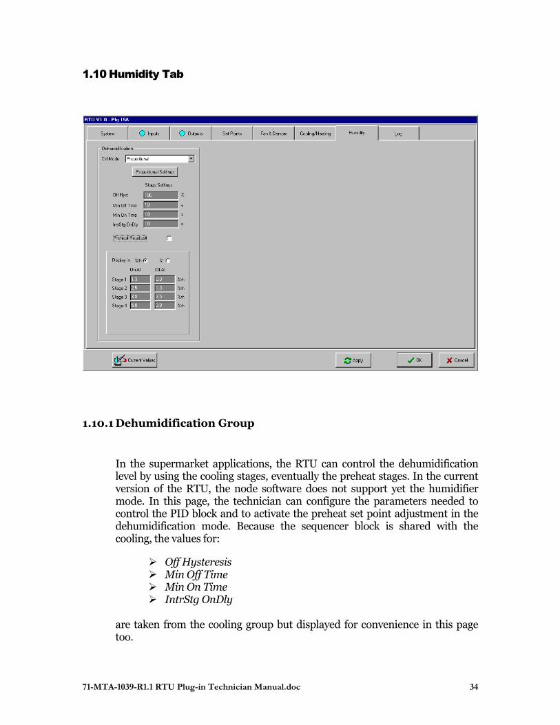
1.10 Humidity Tab
1.10.1 Dehumidification Group
In the supermarket applications, the RTU can control the dehumidification level by using the cooling stages, eventually the preheat stages. In the current version of the RTU, the node software does not support yet the humidifier mode. In this page, the technician can configure the parameters needed to control the PID block and to activate the preheat set point adjustment in the dehumidification mode. Because the sequencer block is shared with the cooling, the values for:
Off Hysteresis Min Off Time Min On Time IntrStg OnDly
are taken from the cooling group but displayed for convenience in this page too.
71-MTA-1039-R1.1 RTU Plug-in Technician Manual.doc 35
Ctrl Mode – depending of the application can be :
Proportional – for most applications PID – for special applications
Proportional /PID Settings – the PID block will compare the space relative humidity with the relative humidity set point and will command the corresponding cooling stages. If the dew point method is chosen, it will compare the current space dew point with the dew point set point.
Preheat Readjust – enable/disable the adjustment of the preheat with the value from the preheat group. Stages Trip Points – indicate the values where the cooling stages will go ON and OFF for the dehumidification mode. The displayed units are consistent with the method of humidity control chosen in the Set Points page. If some cooling stages are active in dehumidification mode, they are drawn in blue.
71-MTA-1039-R1.1 RTU Plug-in Technician Manual.doc 36
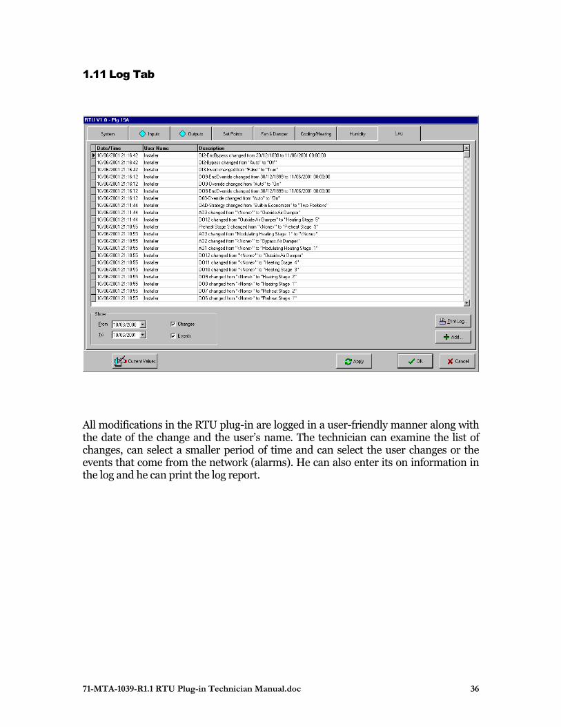
1.11 Log Tab
All modifications in the RTU plug-in are logged in a user-friendly manner along with the date of the change and the user’s name. The technician can examine the list of changes, can select a smaller period of time and can select the user changes or the events that come from the network (alarms). He can also enter its on information in the log and he can print the log report.
71-MTA-1039-R1.1 RTU Plug-in Technician Manual.doc 37
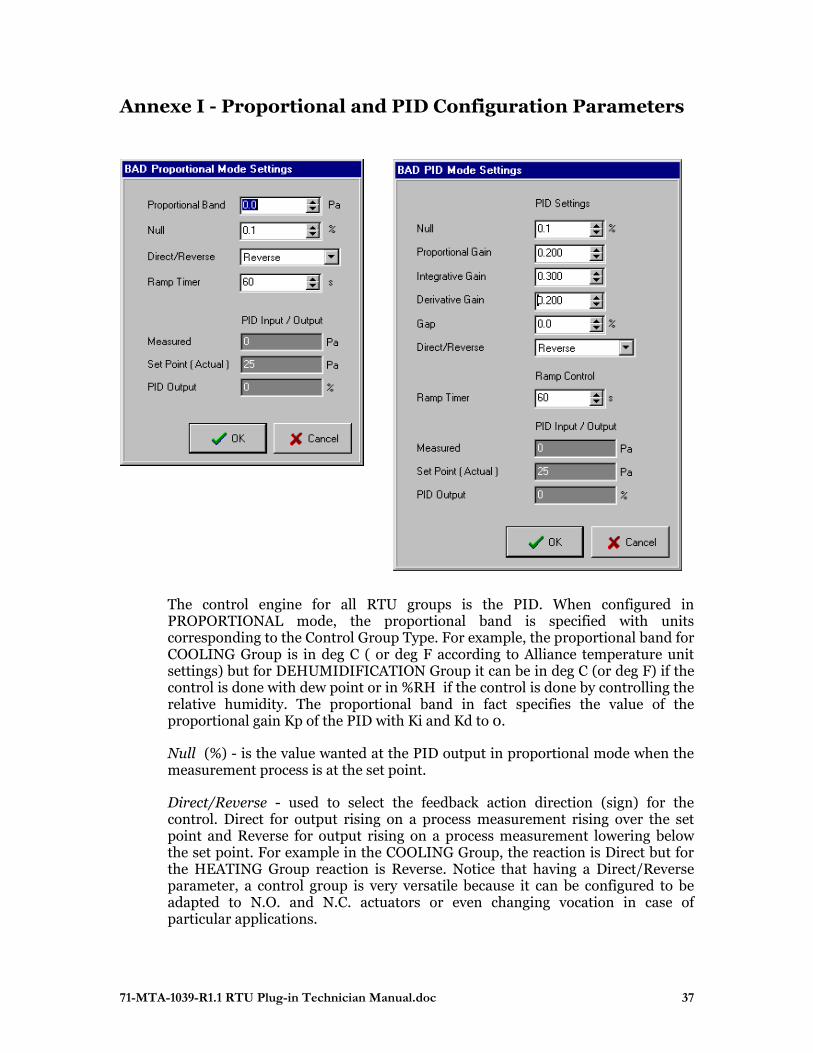
Annexe I - Proportional and PID Configuration Parameters
The control engine for all RTU groups is the PID. When configured in PROPORTIONAL mode, the proportional band is specified with units corresponding to the Control Group Type. For example, the proportional band for COOLING Group is in deg C ( or deg F according to Alliance temperature unit settings) but for DEHUMIDIFICATION Group it can be in deg C (or deg F) if the control is done with dew point or in %RH if the control is done by controlling the relative humidity. The proportional band in fact specifies the value of the proportional gain Kp of the PID with Ki and Kd to 0.
Null (%) - is the value wanted at the PID output in proportional mode when the measurement process is at the set point.
Direct/Reverse - used to select the feedback action direction (sign) for the control. Direct for output rising on a process measurement rising over the set point and Reverse for output rising on a process measurement lowering below the set point. For example in the COOLING Group, the reaction is Direct but for the HEATING Group reaction is Reverse. Notice that having a Direct/Reverse parameter, a control group is very versatile because it can be configured to be adapted to N.O. and N.C. actuators or even changing vocation in case of particular applications.
71-MTA-1039-R1.1 RTU Plug-in Technician Manual.doc 38
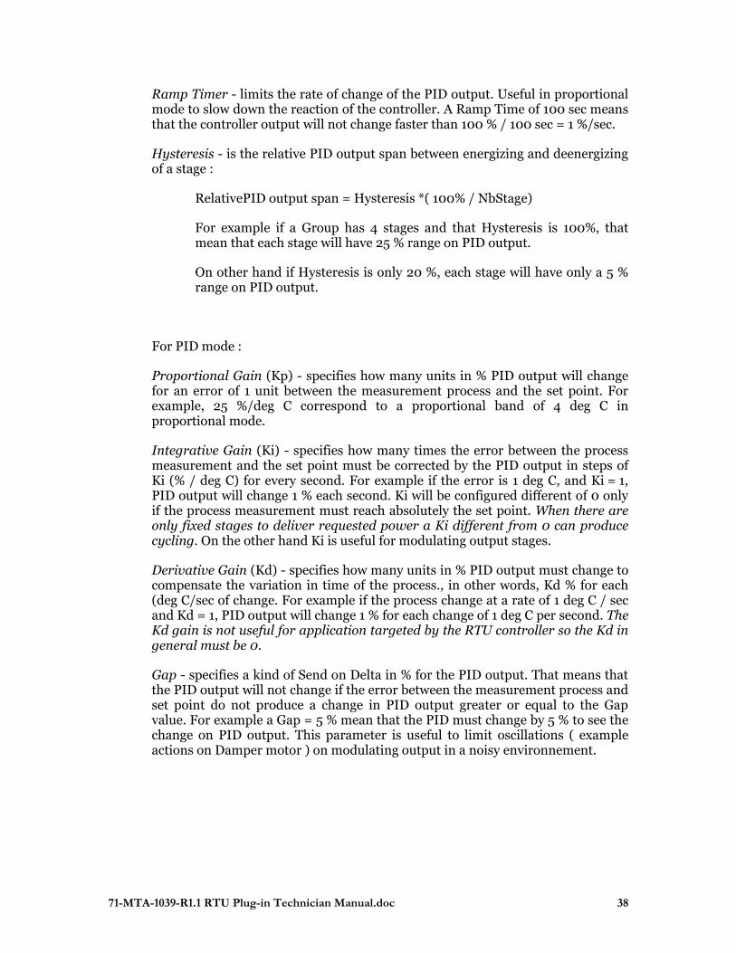
Ramp Timer - limits the rate of change of the PID output. Useful in proportional mode to slow down the reaction of the controller. A Ramp Time of 100 sec means that the controller output will not change faster than 100 % / 100 sec = 1 %/sec.
Hysteresis - is the relative PID output span between energizing and deenergizing of a stage :
RelativePID output span = Hysteresis *( 100% / NbStage)
For example if a Group has 4 stages and that Hysteresis is 100%, that mean that each stage will have 25 % range on PID output.
On other hand if Hysteresis is only 20 %, each stage will have only a 5 % range on PID output.
For PID mode :
Proportional Gain (Kp) - specifies how many units in % PID output will change for an error of 1 unit between the measurement process and the set point. For example, 25 %/deg C correspond to a proportional band of 4 deg C in proportional mode.
Integrative Gain (Ki) - specifies how many times the error between the process measurement and the set point must be corrected by the PID output in steps of Ki (% / deg C) for every second. For example if the error is 1 deg C, and Ki = 1, PID output will change 1 % each second. Ki will be configured different of 0 only if the process measurement must reach absolutely the set point. When there are only fixed stages to deliver requested power a Ki different from 0 can produce cycling. On the other hand Ki is useful for modulating output stages.
Derivative Gain (Kd) - specifies how many units in % PID output must change to compensate the variation in time of the process., in other words, Kd % for each (deg C/sec of change. For example if the process change at a rate of 1 deg C / sec and Kd = 1, PID output will change 1 % for each change of 1 deg C per second. The Kd gain is not useful for application targeted by the RTU controller so the Kd in general must be 0.
Gap - specifies a kind of Send on Delta in % for the PID output. That means that the PID output will not change if the error between the measurement process and set point do not produce a change in PID output greater or equal to the Gap value. For example a Gap = 5 % mean that the PID must change by 5 % to see the change on PID output. This parameter is useful to limit oscillations ( example actions on Damper motor ) on modulating output in a noisy environnement.
71-MTA-1039-R1.1 RTU Plug-in Technician Manual.doc 39
Annexe II – Modulating Heating Group
Modulating Heating stage could be used in three ways.
First, the modulating heating stage can be configured to use its own PID simply by unchecking the option Share Heating PID and by configuring the associated control parameters (see Appendix A for control parameters explanation). The temperature set point in this mode is based on the temperature set point of the Heating Group to which it is possible to add or substract an offset by editing the Offset SP Heat box. This way the temperature set point of the modulating heating stage will depend also on the occupancy mode. A minimum value for starting the modulating heating stage can be programmed in Min Position edit box. By checking the Winter/Summer option the modulating heating stage will be available only in winter. Using the modulating heating stage with its own PID it is possible to change the slope and starting point of the modulating stage by changing proportional band and Offset SP Heat parameters.
The two other ways to used Modulating Heating stage is in Vernier style where the controller is the same as the Heating Group used for the fixed stages. To select this Vernier mode just check the Share Heating PID option. In Vernier mode the modulating heating stage can be the first one to start before fixed stages, by selecting FIRST for Heating Stage option . Otherwise select LAST if there must be one fixed stage energized before modulating the variable heating stage.
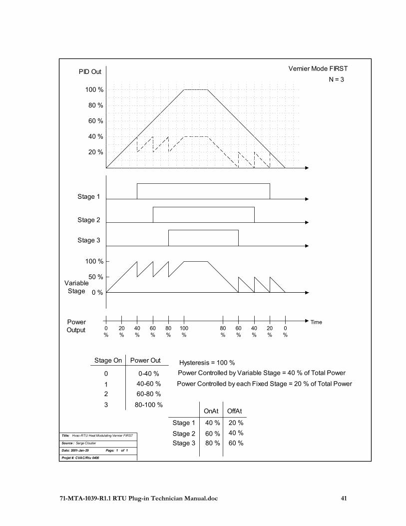
The FIRST mode is useful for controlling electrical heater when actuator is of continuous control type (Thyristor). To configure control parameters, notice that a relation exist between the power of the stages and the Hysteresis. Consider that the power of the variable stage is at least the power of a fixed stage plus a certain percentage of the power of the fixed stage that will be associated with Hysteresis :
Variable Stage Power = Fixed Stage Power + (Hysteresis * Fixed Stage Power)
Total Power = Variable Stage Power + (NbStage fixed * Fixed Stage Power)
For example we suppose a configuration with three 1 kW fixed stages and one 2 kW variable stage. So meaning that Hysteresis must be 100 %. The modulating stage represent 2 kW / (5 kW) = 40 % of the total available power. So when the requested power is lower than 40 %, the modulating stage will vary between 0 - 100% delivering a power between 0 and 2 kW. When the requested power go over 40 % a first fixed stage is energized so this new 1 kW will be substract from the modulating output to keep a continuous power delivery (Vernier effect). The power delivered just after energizing the first fixed stage is 2 kW, exactly the same as just before, but now the power is delivered 50 % by the variable stage and 50 % by the fixed stage. This fixed stage will be deenergized only if the requested power fall down of one hysteresis value, (1 kW in this example because hysteresis is 100 %). So the fixed stage will be deenergized when the modulating heating output will come back to 0 %. And so on for energizing and deenergizing of every fixed stages with the variable stage acting as vernier element between all those possibles configurations. For a given ratio between variable and fixed stages power for a specific physical configuration there will be different a
71-MTA-1039-R1.1 RTU Plug-in Technician Manual.doc 40
corresponding Hysteresis ( see relation above ). Minimum programmable Hysteresis is restricted to 20 % so the power of the variable element cannot be below 1.2 * power of fixed stage. ( For more details see figures below )
The LAST mode is useful when a first fixed stage must be On before starting the modulating stage like for a gas valve and burner. A minimum position can be specified to be sure, for expample to have a minimum flame when the burner is started. Same discussion apply as in FIRST mode for relation between available power and Hysteresis. The only difference is that the Vernier effect is apply after at least a first fixed stage is energized. ( For more details see figures below )
71-MTA-1039-R1.1 RTU Plug-in Technician Manual.doc 41
20 %
40 %
60 %
80 %
100 %
Stage 1
Stage 2
Stage 3
VariableStage
100 %
0 %
N = 3
50 %
Vernier Mode FIRST
Title: Hvac-RTU Heat Modulating Vernier FIRST
Source : Serge Cloutier
Date: 2001-Jan-29 Page: 1 of 1
Projet #: CVAC/Rtu 0400
PID Out
OnAt OffAt
40 %
60 %
80 %
Stage 1
Stage 2
Stage 3
40 %
60 %
20 %
0%
20%
40%
60%
80%
100%
80%
60%
40%
20%
0%
Power Out
0
1
2
3
0-40 %
Stage On
40-60 %
60-80 %
80-100 %
Power Controlled by Variable Stage = 40 % of Total Power
Power Controlled by each Fixed Stage = 20 % of Total Power
Hysteresis = 100 %
PowerOutput
Time

71-MTA-1039-R1.1 RTU Plug-in Technician Manual.doc 42
20 %
40 %
60 %
80 %
100 %
Stage 1
Stage 2
Stage 3
100 %
0 %
Power Out
0
1
2
3
0
Stage On
20-60 %
60-80 %
80-100 %
N = 3
50 %
Vernier Mode LAST
Title: Hvac-RTU Heat Modulating Vernier LAST
Source : Serge Cloutier
Date: 2001-Jan-29 Page: 1 of 1
Projet #: CVAC/Rtu 0400
VariableStage
Power Controlled by Variable Stage = 40 % of Total PowerPower Controlled by each Fixed Stage = 20 % of Total Power
Hysteresis = 100 %
OnAt OffAt
20 %
60 %
80 %
Stage 1
Stage 2
Stage 3
40 %
60 %
0 %
0%
20%
40%
60%
80%
100%
80%
60%
40%
20%
0%
Time
71-MTA-1039-R1.1 RTU Plug-in Technician Manual.doc 43
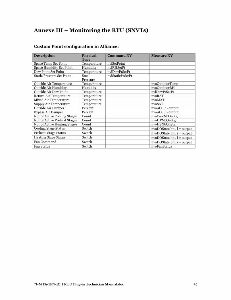
Annexe III – Monitoring the RTU (SNVTs) Custom Point configuration in Alliance: Description Physical
Type Command NV Measure NV
Space Temp Set Point Temperature nviSetPoint Space Humidity Set Point Humidity nviRHSetPt Dew Point Set Point Temperature nviDewPtSetPt Static Pressure Set Point Small
Pressure nviStaticPrSetPt
Outside Air Temperature Temperature nvoOutdoorTemp Outside Air Humidity Humidity nvoOutdoorRH Outside Air Dew Point Temperature nviDewPtSetPt Return Air Temperature Temperature nvoRAT Mixed Air Temperature Temperature nvoMAT Supply Air Temperature Temperature nvoSAT Outside Air Damper Percent nvoAOI , i=output Bypass Air Damper Percent nvoAOI , i=output Nbr of Active Cooling Stages Count nvoCoolNbOnStg Nbr of Active Preheat Stages Count nvoHPNbOnStg Nbr of Active Heating Stages Count nvoHSNbOnStg Cooling Stage Status Switch nvoDOState.biti, i = output Preheat Stage Status Switch nvoDOState.biti, i = output Heating Stage Status Switch nvoDOState.biti, i = output Fan Command Switch nvoDOState.biti, i = output Fan Status Switch nvoFanStatus

71-MTA-1039-R1.1 RTU Plug-in Technician Manual.doc 44
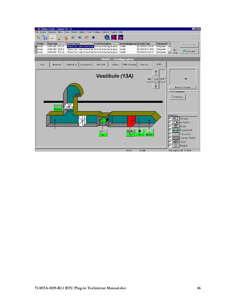
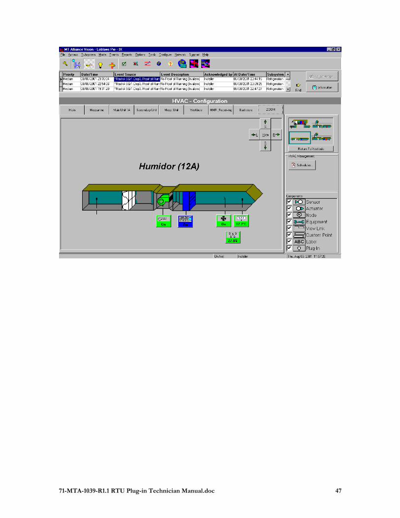
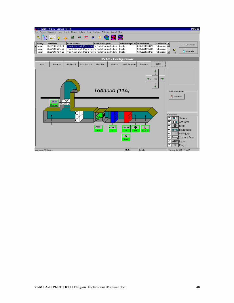
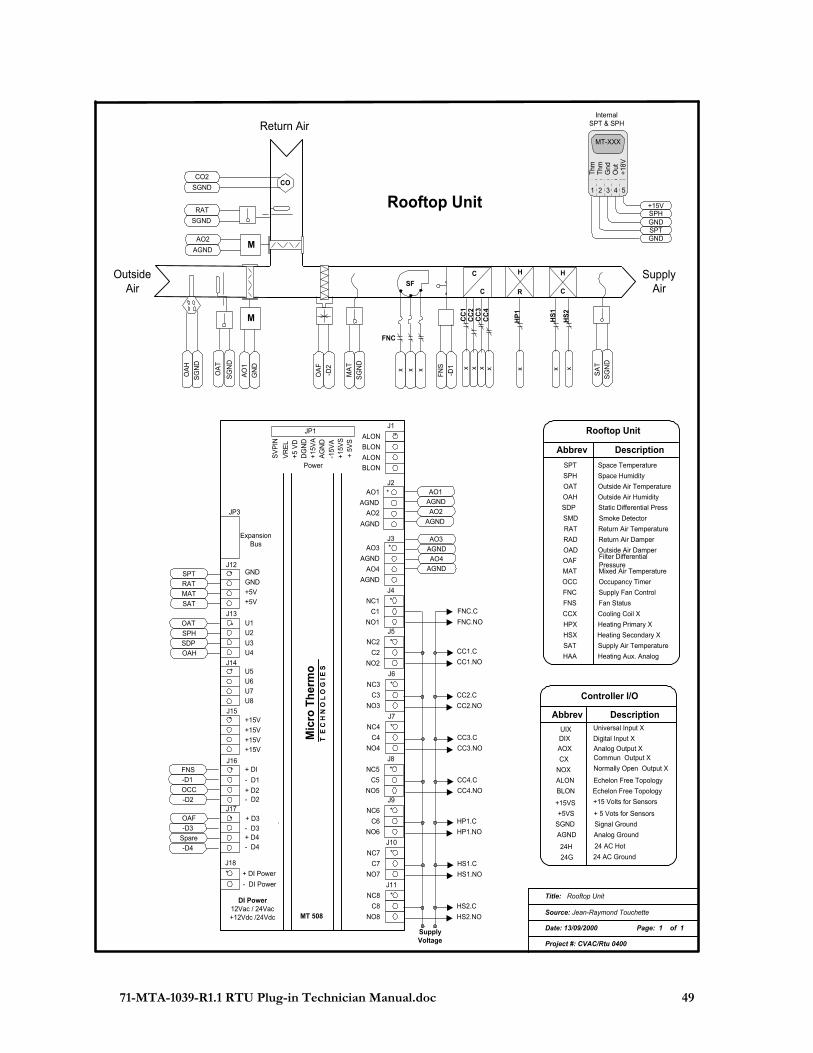
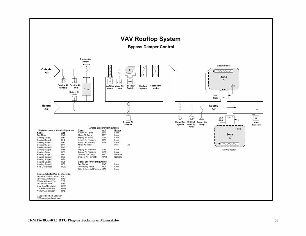
Annexe IV – RTU Mechanical & Electrical Layout Examples of RTU applications:
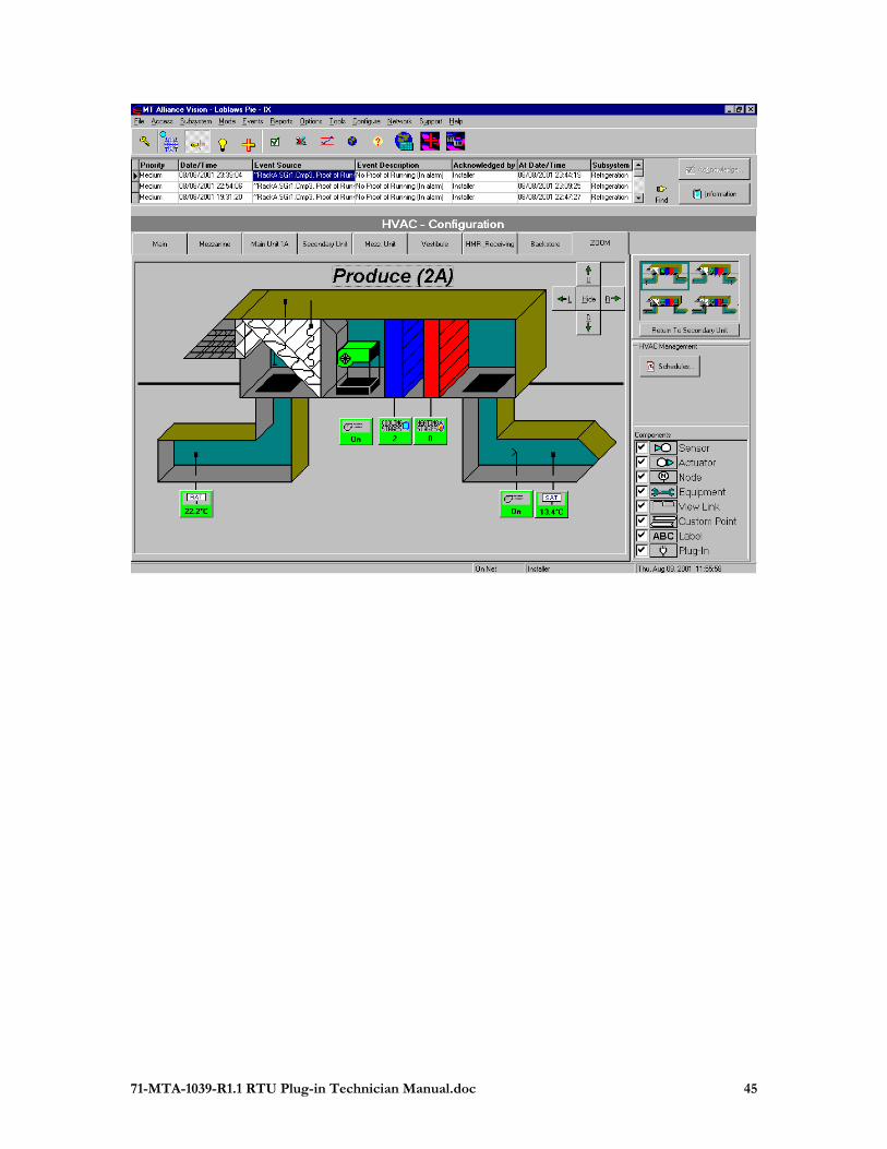
71-MTA-1039-R1.1 RTU Plug-in Technician Manual.doc 45
71-MTA-1039-R1.1 RTU Plug-in Technician Manual.doc 46
71-MTA-1039-R1.1 RTU Plug-in Technician Manual.doc 47
71-MTA-1039-R1.1 RTU Plug-in Technician Manual.doc 48
71-MTA-1039-R1.1 RTU Plug-in Technician Manual.doc 49
xH
S1
H
C
x x
C
C
CC
1C
C2
x x
CC
3C
C4
H
R
Title: Rooftop Unit
Source: Jean-Raymond Touchette
Date: 13/09/2000 Page: 1 of 1
Project #: CVAC/Rtu 0400
OutsideAir
Return Air
Rooftop Unit
SupplyAir
RAT
SGND
AO2
AGNDM
OA
F
-D2
MA
T
SG
ND
x x x
SF
FN
S
-D1
SG
ND
SA
T
MT-XXX
Out
Gnd
Thm
Thm
InternalSPT & SPH
+15VSPH
SPTGND
+18V
1 2 3 4 5
GND
FNC
OA
H
SG
ND
OA
T
SG
ND
COCO2
SGND
M
GN
D
AO
1
Abbrev Description
SMD
RAT
RAD
OAD
OAF
MAT
FNC
FNS
HPX
HSX
SAT
Smoke Detector
Return Air Damper
Outside Air DamperFilter DifferentialPressureMixed Air Temperature
Supply Air Temperature
Return Air Temperature
Fan Status
Heating Primary X
Heating Secondary X
Supply Fan Control
Rooftop Unit
OCC Occupancy Timer
SPH
SPT
OAT
OAH
Space Temperature
Space Humidity
Outside Air Humidity
Outside Air Temperature
HAA Heating Aux. Analog
CCX Cooling Coil X
SDP Static Differential Press
SupplyVoltage
AGND
AO2
AO1
FNC.C
FNC.NO
CC1.C
CC1.NO
AGND
AGND
AO4
AO3
AGND* GND
GND
+5V+5V
J12
* U1U2
U3U4
J13
* U5
U6
U7U8
J14
C8
NC8
NO8
J11
*
C7
NC7
NO7
J10
*
C6
NC6
NO6
J9
*
C3
NC3
NO3
J6
*
C4
NC4
NO4
J7
*
Power
*
ALON
BLON
ALON
BLON
AGND
AO2
AGND
AO1J2
J1
Mic
ro T
her
mo
T E
C H
N O
L O
G I
E S
*
AGND
AO4
AGND
AO3J3Expansion
Bus
JP3
*
C1
NC1
NO1
J4
*
C2
NC2
NO2
J5
*
C5
NC5
NO5
J8
*
SV
PIN
VR
EL
+5 V
DD
GN
D+1
5VA
AG
ND
-15V
A
+ 5V
S+1
5VS
JP1
* +15V
+15V
+15V+15V
J15
* + DI
- D1
+ D2- D2
J16
* + D3
+ D4- D3
- D4
J17
*
- DI Power
+ DI Power
J18
DI Power12Vac / 24Vac+12Vdc /24Vdc MT 508
CC2.C
CC2.NO
CC3.C
CC3.NO
CC4.C
CC4.NO
HP1.C
HP1.NO
HS1.C
HS1.NO
HS2.C
HS2.NO
xH
S2
xH
P1
Abbrev Description
Controller I/O
UIX DIX
AOX
CX
NOX
BLON
ALON
+5VS
+15VS
AGND
SGND
24G
24H
Universal Input X
Digital Input X
Commun Output X
Normally Open Output X
Echelon Free Topology
Echelon Free Topology
Analog Output X
+ 5 Vots for Sensors
Signal Ground
Analog Ground
24 AC Hot
24 AC Ground
+15 Volts for Sensors
SPT
RAT
MAT
SAT
OAT
SPH
SDP
OAH
FNS
-D1
-D2
-D4
OAF
OCC
Spare
-D3
71-MTA-1039-R1.1 RTU Plug-in Technician Manual.doc 50
Outside Air
ReturnAir
SupplyAir
Mixed AirTemp
AirFilterSwitch
Outside AirDamper
Outside AirHumidity
Outside AirTemp
HumidifierSystem
Supply AirTemp
Econo
Bypass AirDamper
ZoneX
Zone1
Fan FlowSwitch
F
Electric Heater
Electric Heater
SecondaryHeating
H
H
C
C
CoolingSystem
Sp
StaticPressure
VAVBOX
T
VAVBOX
T
VAV Rooftop SystemBypass Damper Control
Return AirTemp
Hi LimitHumidity
AI/DIAnalog Sensors ConfigurationName Abb SourceReturn Air Temp RAT LocalMixed AIr Temp MAT LocalSupply Air Temp SAT LocalReturn Air Pressure RAP LocalReturn Air Humidity RAH LocalMixed Air Filter MAF LocalSupply Air Humidity SAH LocalSupply Air Pressure SAP LocalOutdoor Air Temp OAT NetwookOutdoor Air Humidity OAH Network
Digital Sensors ConfigurationFan Status FNS LocalOccupancy Timer OCC LocalFilter Differential Pressure OAF Local
Digital Actuators Max ConfigurationName AbbFan Motor FNCCooling Stage 1 DX1Cooling Stage 2 DX2Cooling Stage 3 DX3Cooling Stage 4 DX4Cooling Stage 5 DX5Cooling Stage 6 DX6Heating Stage 1 HS1Heating Stage 2 HS2Heating Stage 3 HS3Heating Stage 4 HS4Heating Stage 5 HS5Heating Stage 6 HS6Heat Gas Enable HGE
Analog Actuator Max Configuration?Fan Inlet Guided Vane FIV?Bypass Air Damper BAD?Variable Speed Fan VSF?Fan Blade Pitch FBPHeat Gas Modulation HGM*Outside Air Damper OAD*Return Air Damper RAD
? Depend on SAT Stragegy* If Economizer is not used