Embed Size (px)
Citation preview
PACKING LIST Compu Flow Manual Valve Body Separator Plate Valve Body Gaskets (2) Transmission Pan Gasket Filter Seal Ring Heavy Duty Servo Kit
Internal Wiring harnessWire Splice Connectors (2)Fourth Gear pressure Switch.500” Boost valvePurple Pressure Regulator SpringPressure Regulator Retaining Ring
NOTE: On transmission components not being used, you can save and store the pieces to convert your trans mis sion back to OEM specs if you so desire.
STEP 1: Drain the oil pan. You will need a pan to catch fl uid. Remove transmission oil pan bolts. When re mov ing bolts, remove so pan will not drop completely off but will be held into place so that one side will allow the fl uid to be drained. After the fl uid has drained, remove the rest of the bolts and pour out the remaining fl uid. Re move gasket and discard. If gasket ma te ri al sticks to transmission pan or case. Remove all material com plete ly. A 700 R-4 trans mis sion does not have a drain plug. You may want to install a universal drain plug kit into your pan now that you have the pan off.
STEP 2: Carefully remove the oil fi lter by pull ing it straight down. Remove the pickup tube o-ring from the pump if it does not come out with the fi lter. Dis card the o-ring. There is a small gasket that fi ts on the fi lter tube. Make sure it is still on the fi lter tube. If not, remove it from the case. In spect the oil fi lter. Replace the fi lter if it is dirty or has not been changed in over 25,000 miles.
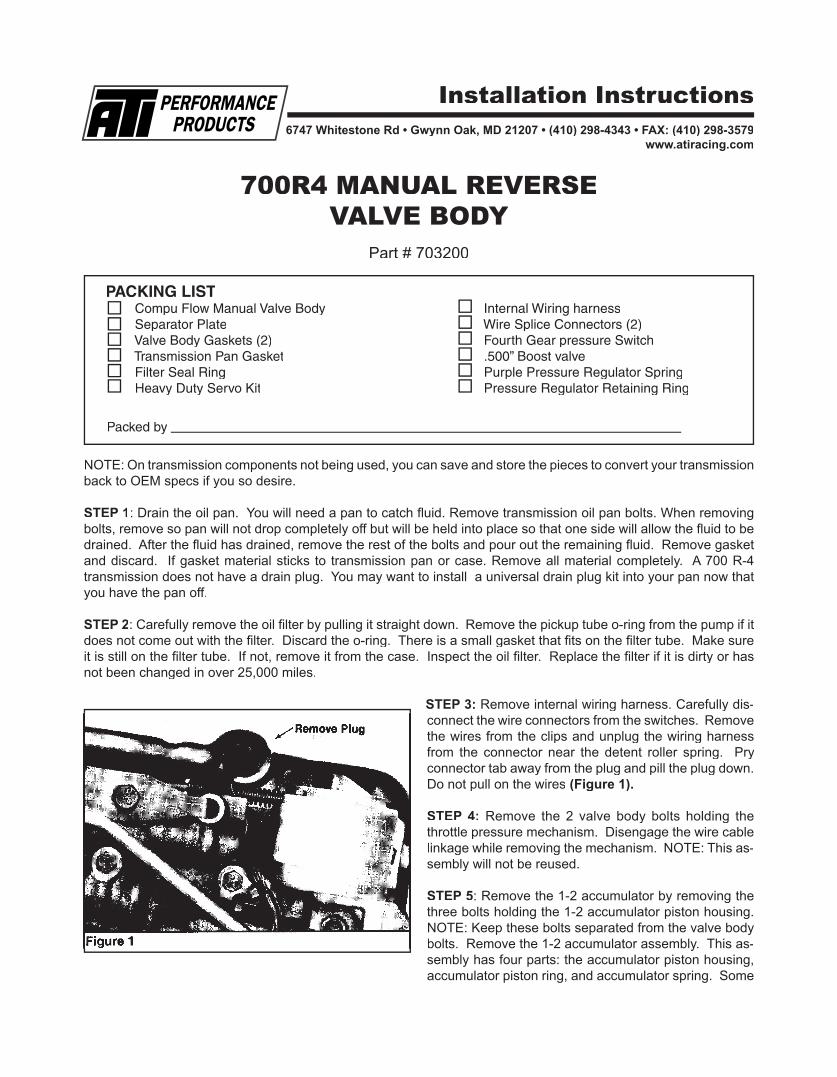
STEP 3: Remove internal wiring harness. Carefully dis- con nect the wire con nec tors from the switches. Re move the wires from the clips and unplug the wiring har ness from the con nec tor near the detent roller spring. Pry con nec tor tab away from the plug and pill the plug down. Do not pull on the wires (Figure 1).
STEP 4: Remove the 2 valve body bolts holding the throt tle pres sure mechanism. Disengage the wire ca ble linkage while re mov ing the mechanism. NOTE: This as- sem bly will not be re used.
STEP 5: Remove the 1-2 accumulator by removing the three bolts holding the 1-2 accumulator piston housing. NOTE: Keep these bolts separated from the valve body bolts. Remove the 1-2 accumulator assembly. This as- sem bly has four parts: the accumulator piston housing, ac cu mu la tor piston ring, and accumulator spring. Some
700R4 MANUAL REVERSEVALVE BODY
Part # 703200
6747 Whitestone Rd • Gwynn Oak, MD 21207 • (410) 298-4343 • FAX: (410) 298-3579www.atiracing.com
Installation Instructions
Packed by
earlier mod els will also have a thick support plate between the ac cu mu la tor hous ing and the sep a ra tor plate, If your trans mis sion has this plate, re move it carefully. Be sure not to damage the gasket. This gasket must be reused. NOTE: located under the pressure plate is the 3-4 as sem bly. It will be removed after the valve body has been re moved.
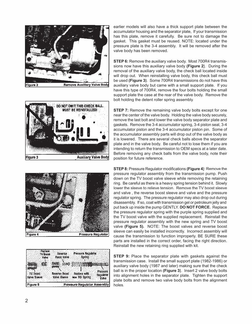
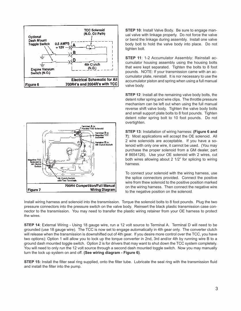
STEP 6: Remove the auxiliary valve body. Most 700R4 trans mis -sions now have this auxiliary valve body (Figure 2). During the removal of the aux il ia ry valve body, the check ball located inside will drop out. When re in stall ing valve body, this check ball must be used (Figure 3). Some 700R4 trans mis sions do not have this auxiliary valve body but came with a small support plate. If you have this type of 700R4, remove the four bolts holding the small support plate the case at the rear of the valve body. Re move the bolt holding the detent roller spring as sem bly.
STEP 7: Remove the remaining valve body bolts ex cept for one near the center of the valve body. Holding the valve body se cure ly, remove the last bolt and lower the valve body sep a ra tor plate and gas kets. Remove the 3-4 ac cu mu la tor spring, 3-4 pis ton seal, 3-4 ac cu mu la tor piston and the 3-4 ac cu mu la tor piston pin. Some of the accumulator as sem bly parts will drop out of the valve body as it is low ered. There are sev er al check balls above the sep a ra tor plate and in the valve body. Be care ful not to lose them if you are intending to return the trans mis sion to OEM specs at a later date. Before re mov ing any check balls from the valve body, note their po si tion for future ref er ence.
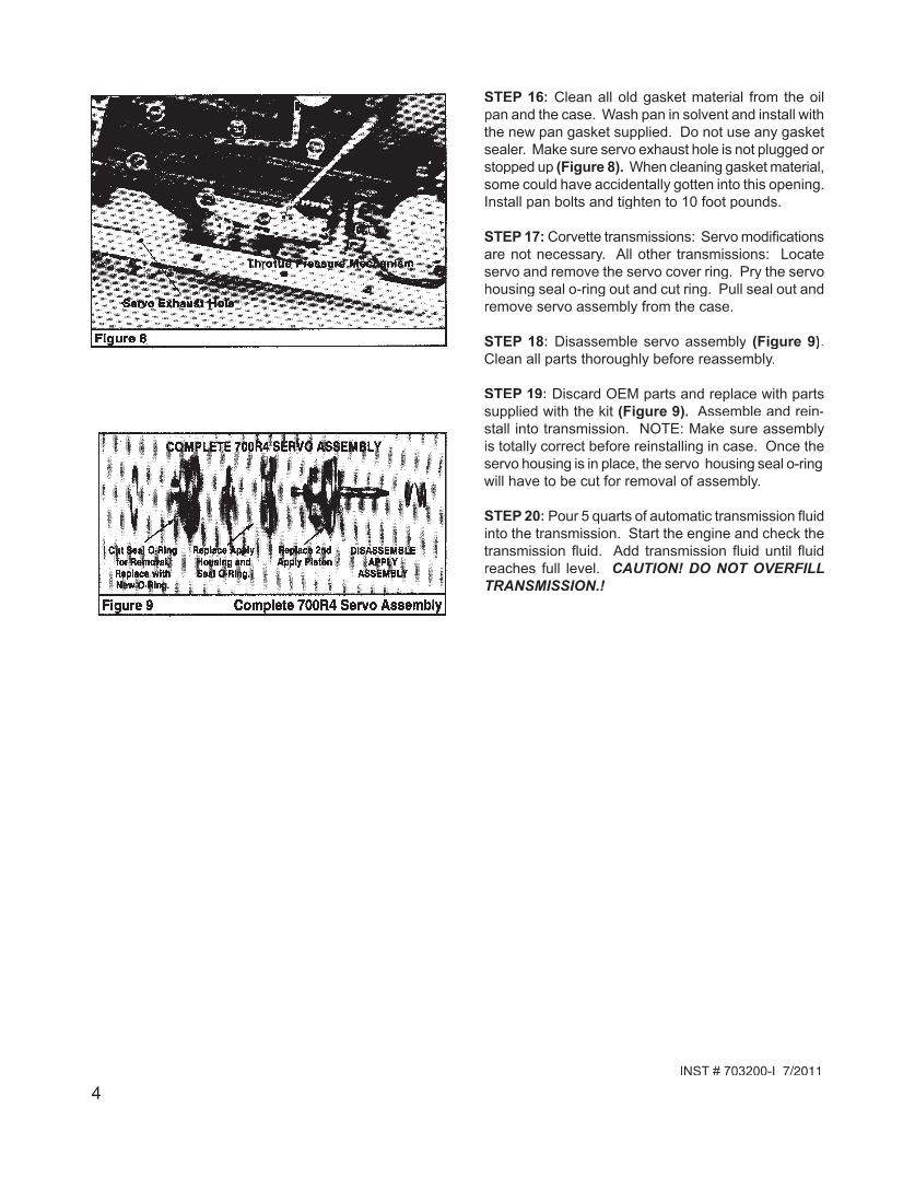
STEP 8: Pressure Regulator modifi cations (Figure 4): Re move the pres sure regulator assembly from the trans mis sion pump. Push down on the TV boost valve sleeve while re mov ing the re tain ing ring. Be careful as there is a heavy spring tension behind it. Slow ly lower the sleeve to relieve tension. Remove the TV boost sleeve and valve , the re verse boost sleeve and valve and the pressure reg u la tor spring. The pressure reg u la tor may also drop out dur ing dis as sem bly. If so, coat with trans mis sion gel or pe tro leum jelly and put back up inside the pump GEN TLY. DO NOT FORCE. Re place the pressure reg u la tor spring with the purple spring supplied and the TV boost valve with the sup plied re place ment. Re in stall the pressure reg u la tor as sem bly with the new spring and TV boost valve (Figure 5). NOTE: The boost valves and re verse boost sleeve can eas i ly be in stalled in cor rect ly. Incorrect as sem bly will cause the trans mis sion to func tion im prop er ly. BE SURE these parts are in stalled in the cor rect or der, facing the right di rec tion. Re in stall the new re tain ing ring supplied with kit.
STEP 9: Place the separator plate with gaskets against the trans mis sion case. Install the small support plate (1982-1986) or aux il ia ry valve body (1987 and later) making sure that the check ball is in the proper location (Figure 3). Insert 2 valve body bolts into alignment holes in the separator plate. Tighten the support plate bolts and remove two valve body bolts from the alignment holes.
2
STEP 10: Install Valve Body. Be sure to en gage man- u al valve with linkage properly. Do not force the valve or bend the linkage dur ing assembly. Install one valve body bolt to hold the valve body into place. Do not tight en bolt.
STEP 11: 1-2 Accumulator Assembly: Re in stall ac- cu mu la tor housing assembly using the hous ing bolts that were kept separated. Tight en the bolts to 8 foot pounds. NOTE: If your trans mis sion came with an ac- cu mu la tor plate, re in stall. It is nor necessary to use the ac cu mu la tor piston and spring when us ing a full manual valve body.
STEP 12: Install all the remaining valve body bolts, the detent roller spring and wire clips. The throttle pressure mechanism can be left out when using the full manual reverse shift valve body. Tighten the valve body bolts and small support plate bolts to 8 foot pounds. Tighten detent roller spring bolt to 10 foot pounds. Do not over tight en.
STEP 13: Installation of wiring harness: (Figure 6 and 7): Most applications will ac cept the OE so le noid. All 2 wire solenoids are ac cept able. If you have a so- le noid with only one wire, it cannot be used. (You may pur chase the proper solenoid from a GM dealer, part # 8654126). Use your OE so le noid with 2 wires, cut both wires allowing about 2 1/2” for splicing to wiring har ness.
To connect your solenoid with the wiring har ness, use the splice connectors provided. Con nect the pos i tive wire from thew so le noid to the pos i tive po si tion marked on the wiring har ness. Then connect the negative wire to the neg a tive po si tion on the so le noid.
Install wiring harness and solenoid into the trans mis sion. Torque the so le noid bolts to 8 foot pounds. Plug the two pres sure con nec tors into the pressure switch on the valve body. Reinsert the black plastic trans mis sion case con- nec tor to the transmission. You may need to transfer the plastic wiring retainer from your OE har ness to protect the wires.
STEP 14: External Wiring - Using 18 gauge wire, run a 12 volt source to Terminal A. Terminal D will need to be ground ed (use 18 gauge wire). The TCC is now set to engage au to mat i cal ly in 4th gear only. The converter clutch will release when the transmission is down shift ed out of 4th gear. If you desire more control over the TCC, you have two options): Option 1 will allow you to lock up the torque con vert er in 2nd, 3rd and/or 4th by running wire B to a ground dash mount ed toggle switch. Option 2 is for driv ers that may want to shut down the TCC sys tem com plete ly. You will need to only run the 12 volt source through a sec ond dash mounted toggle switch. Now you may manually turn the lock up system on and off. (See wiring diagram - Figure 6).
STEP 15: Install the fi lter seal ring supplied, onto the fi lter tube. Lubricate the seal ring with the trans mis sion fl uid and install the fi lter into the pump.
3
STEP 16: Clean all old gasket material from the oil pan and the case. Wash pan in solvent and install with the new pan gasket supplied. Do not use any gasket sealer. Make sure servo exhaust hole is not plugged or stopped up (Figure 8). When cleaning gasket ma te ri al, some could have accidentally gotten into this open ing. Install pan bolts and tighten to 10 foot pounds.
STEP 17: Corvette transmissions: Servo mod i fi ca tions are not necessary. All other trans mis sions: Lo cate servo and remove the servo cover ring. Pry the servo housing seal o-ring out and cut ring. Pull seal out and remove servo assembly from the case.
STEP 18: Disassemble servo assembly (Fig ure 9). Clean all parts thoroughly before re as sem bly.
STEP 19: Discard OEM parts and replace with parts supplied with the kit (Figure 9). Assemble and re in -stall into transmission. NOTE: Make sure as sem bly is to tal ly correct before reinstalling in case. Once the ser vo housing is in place, the ser vo hous ing seal o-ring will have to be cut for removal of assembly.
STEP 20: Pour 5 quarts of automatic transmission fl u id into the transmission. Start the engine and check the transmission fl uid. Add transmission fl u id until fl uid reaches full level. CAUTION! DO NOT OVER FILL TRANS MIS SION.!
INST # 703200-I 7/2011
4


![Pneumatic components for high-pressure applications · 2019. 10. 4. · Electric pressure regulator Electric pressure regulator with shut-off valve PAHL Operating pressure [bar] 0](https://img.pdfslide.us/doc/110x75/60fe30ad1a699b07e6361388/pneumatic-components-for-high-pressure-applications-2019-10-4-electric-pressure.jpg)