Embed Size (px)
Citation preview

VFAULT up to 70 V
INV Input Can Correctfor Crossed Wires
SN65HVD1794, SN65HVD1795SN65HVD1796
www.ti.com SLLS935A –AUGUST 2008–REVISED AUGUST 2012
70-V Fault-Protected RS-485 Transceiver With Cable InvertCheck for Samples: SN65HVD1794, SN65HVD1795, SN65HVD1796
1FEATURES• Bus-Pin Fault Protection to > ±70 V • Failsafe Receiver for Open-Circuit, Short-
Circuit and Idle-Bus Conditions• Cable Invert Function Allows Correction forReversed Bus Pins • Low Power Consumption
• Common-Mode Voltage Range (–20 V to 25 V) – ICC 5 mA Quiescent During OperationMore Than Doubles TIA/EIA 485 Requirement • Power-Up, Power-Down Glitch-Free Operation
• Bus I/O ProtectionAPPLICATIONS– ±16 kV JEDEC HBM Protection• Designed for RS-485 and RS-422 Networks• Reduced Unit Load for Up to 256 Nodes
DESCRIPTIONThese devices are designed to survive overvoltage faults such as direct shorts to power supplies, mis-wiringfaults, connector failures, cable crushes, and tool mis-applications. They are also robust to ESD events, with highlevels of protection to human-body model specifications.
These devices combine a differential driver and a differential receiver, which operate from a single power supply.The driver differential outputs and the receiver differential inputs are connected internally to for a bus portsuitable for half-duplex (two-wire bus) communication. A cable invert pin (INV) allows active correction of mis-wires that may occur during installation. Upon detecting communication errors, the user can apply a logic HIGHto the INV pin, effectively inverting the polarity of the differential bus port, thereby correcting for the reversed buswires.
These devices feature a wide common-mode voltage range, making them suitable for multi-point applicationsover long cable runs. These devices are characterized from –40°C to 105°C.
Table 1. PRODUCT SELECTION GUIDE
PART NUMBER DUPLEX SIGNALING RATE NODES CABLE LENGTH
SN65HVD1794 Half 115 kbps Up to 256 1500 m
SN65HVD1795 PREVIEW Half 1 Mbps Up to 256 150 m
SN65HVD1796 PREVIEW Half 10 Mbps Up to 64 50 m
For similar features with 3.3 V supply operation, see the SN65HVD1781 (SLLS877).
1
Please be aware that an important notice concerning availability, standard warranty, and use in critical applications ofTexas Instruments semiconductor products and disclaimers thereto appears at the end of this data sheet.
UNLESS OTHERWISE NOTED this document contains Copyright © 2008–2012, Texas Instruments IncorporatedPRODUCTION DATA information current as of publication date.Products conform to specifications per the terms of TexasInstruments standard warranty. Production processing does notnecessarily include testing of all parameters.

3
4
1
2
6
7
A
B
R
DE
D
INV
S0311-01
R
INV
DE
D
VCC
B
A
GND
D Package(Top View)
1
2
3
4
8
7
6
5
P0066-04
SN65HVD1794, SN65HVD1795SN65HVD1796
SLLS935A –AUGUST 2008–REVISED AUGUST 2012 www.ti.com
This integrated circuit can be damaged by ESD. Texas Instruments recommends that all integrated circuits be handled withappropriate precautions. Failure to observe proper handling and installation procedures can cause damage.
ESD damage can range from subtle performance degradation to complete device failure. Precision integrated circuits may be moresusceptible to damage because very small parametric changes could cause the device not to meet its published specifications.
DEVICE INFORMATION
Figure 1. SN65HVD17xx With Inverting Feature to Correct for Miswired Cables
DRIVER FUNCTION TABLEINPUT ENABLE INVERT OUTPUTS
D DE INV A B
H H L H L Actively drive normal bus High
L H L L H Actively drive normal bus Low
H H H L H Actively drive inverted bus High (drive normal busLow)
L H H H L Actively drive inverted bus Low (drive normal busHigh)
X L X Z Z Driver disabled
X OPEN X Z Z Driver disabled by default
OPEN H L H L Actively drive bus High by default
OPEN H H L H Actively drive bus Low by default (inverted cable)
RECEIVER FUNCTION TABLEDIFFERENTIAL INPUT INVERT OUTPUT
VID = VA – VB INV R
L or OPEN H Receive valid bus HighVIT+ < VID
H L Receive inverted bus Low
VIT– < VID < VIT+ X ? Indeterminate bus state
L or OPEN L Receive valid bus LowVID < VIT–
H H Receive inverted bus High
L or OPEN H Fail-safe high outputOpen-circuit bus
H L Failsafe inverted output
L or OPEN H Fail-safe high outputShort-circuit bus
H L Failsafe inverted output
L or OPEN H Fail-safe high outputIdle (terminated) bus
H L Failsafe inverted output
2 Submit Documentation Feedback Copyright © 2008–2012, Texas Instruments Incorporated
Product Folder Links: SN65HVD1794, SN65HVD1795 SN65HVD1796

SN65HVD1794, SN65HVD1795SN65HVD1796
www.ti.com SLLS935A –AUGUST 2008–REVISED AUGUST 2012
ABSOLUTE MAXIMUM RATINGS (1)
VALUE UNIT
VCC Supply voltage –0.5 to 7 V
Voltage range at A and B pins with respect to GND –70 to 70 V
Voltage range across A and B pins (differential) –70 to 70 V
Input voltage range at any logic pin –0.3 to VCC + 0.3 V
Voltage input range, transient pulse, A and B, through 100 Ω –100 to 100 V
Receiver output current –24 to 24 mA
TJ Junction temperature 170 °C
Continuous total power dissipation See Dissipation Rating Table
IEC 60749-26 ESD (human-body model), bus terminals and GND ±16 kV
JEDEC Standard 22, Test Method A114 (human-body model), bus terminals and GND ±16 kV
JEDEC Standard 22, Test Method A114 (human-body model), all pins ±4 kV
JEDEC Standard 22, Test Method C101 (charged-device model), all pins ±2 kV
JEDEC Standard 22, Test Method A115 (machine model), all pins ±400 V
(1) Stresses beyond those listed under absolute maximum ratings may cause permanent damage to the device. These are stress ratingsonly and functional operation of the device at these or any other conditions beyond those indicated under recommended operatingconditions is not implied. Exposure to absolute-maximum-rated conditions for extended periods may affect device reliability.
PACKAGE DISSIPATION RATINGSJEDEC THERMAL TA < 25°C DERATING FACTOR TA = 85°C TA = 105°C
PACKAGE MODEL RATING ABOVE TA = 25°C RATING RATING
High-K 905 mW 7.25 mW/°C 470 mW 325 mWSOIC (D) 8-pin
Low-K 516 mW 4.1 mW/°C 268 mW 186 mW
High-K 2119 mW 16.9 mW/°C 1100 mW 763 mWPDIP (P) 8-pin
Low-K 976 mW 7.8 mW/°C 508 mW 352 mW
RECOMMENDED OPERATING CONDITIONSMIN NOM MAX UNIT
VCC Supply voltage 4.5 5 5.5 V
VI Input voltage at any bus terminal (separately or common mode) (1) –20 25 V
VIH High-level input voltage (driver, driver enable, and invert inputs) 2 VCC V
VIL Low-level input voltage (driver, driver enable, and invert inputs) 0 0.8 V
VID Differential input voltage –25 25 V
Output current, driver –60 60 mAIO
Output current, receiver –8 8 mA
RL Differential load resistance 54 60 ΩCL Differential load capacitance 50 pF
HVD1794 115 kbps
1/tUI Signaling rate HVD1795 1Mbps
HVD1796 10
TA Operating free-air temperature (See application section for thermal information) –40 105 °C
TJ Junction temperature –40 150 °C
(1) By convention, the least positive (most negative) limit is designated as minimum in this data sheet.
Copyright © 2008–2012, Texas Instruments Incorporated Submit Documentation Feedback 3
Product Folder Links: SN65HVD1794, SN65HVD1795 SN65HVD1796

SN65HVD1794, SN65HVD1795SN65HVD1796
SLLS935A –AUGUST 2008–REVISED AUGUST 2012 www.ti.com
ELECTRICAL CHARACTERISTICSover recommended operating conditions (unless otherwise noted)
PARAMETER TEST CONDITIONS MIN TYP MAX UNIT
RS-485 with TA ≤ 85°C 1.5common-mode load,VCC > 4.75 V, see TA ≤ 105°C 1.4
|VOD| Driver differential output voltage magnitude VFigure 2
RL = 54 Ω, 4.75 V ≤ VCC ≤ 5.25 V 1.5 2
RL = 100 Ω, 4.75 V ≤ VCC ≤ 5.25 V 2 2.5
Change in magnitude of driver differential outputΔ|VOD| RL = 54 Ω –0.2 0 0.2 Vvoltage
VOC(SS) Steady-state common-mode output voltage 1 VCC/2 3 V
Change in differential driver output common-ΔVOC –100 0 100 mVmode voltage
Peak-to-peak driver common-mode output Center of two 27-Ω load resistors, SeeVOC(PP) 500 mVvoltage Figure 3
COD Differential output capacitance 23 pF
Positive-going receiver differential input voltageVIT+ –100 –10 mVthreshold
Negative-going receiver differential inputVIT– –200 –150 mVvoltage threshold VCM = –20 V to 25 V
Receiver differential input voltage thresholdhysteresisVHYS 30 50 mV(VIT+ – VIT–)
VCCVOH Receiver high-level output voltage IOH = –8 mA 2.4 V– 0.3
TA ≤ 85°C 0.2 0.4VOL Receiver low-level output voltage IOL = 8 mA V
TA ≤ 105°C 0.2 0.5
Driver input, driver enable, and invert inputII –100 100 μAcurrent
IOS Driver short-circuit output current –250 250 mA
VI = 12 V 75 12594, 95
VI = –7 V –100 –40VCC = 4.5 to 5.5 V orII Bus input current (disabled driver) μA
VCC = 0 V, DE at 0 V VI = 12 V 50096
VI = –7 V –400
Driver enabled DE = 5V 4 6 mAICC Supply current (quiescent)
Driver disabled DE = GND 2 4
Supply current (dynamic) See TYPICAL CHARACTERISTICS section
4 Submit Documentation Feedback Copyright © 2008–2012, Texas Instruments Incorporated
Product Folder Links: SN65HVD1794, SN65HVD1795 SN65HVD1796
SN65HVD1794, SN65HVD1795SN65HVD1796
www.ti.com SLLS935A –AUGUST 2008–REVISED AUGUST 2012
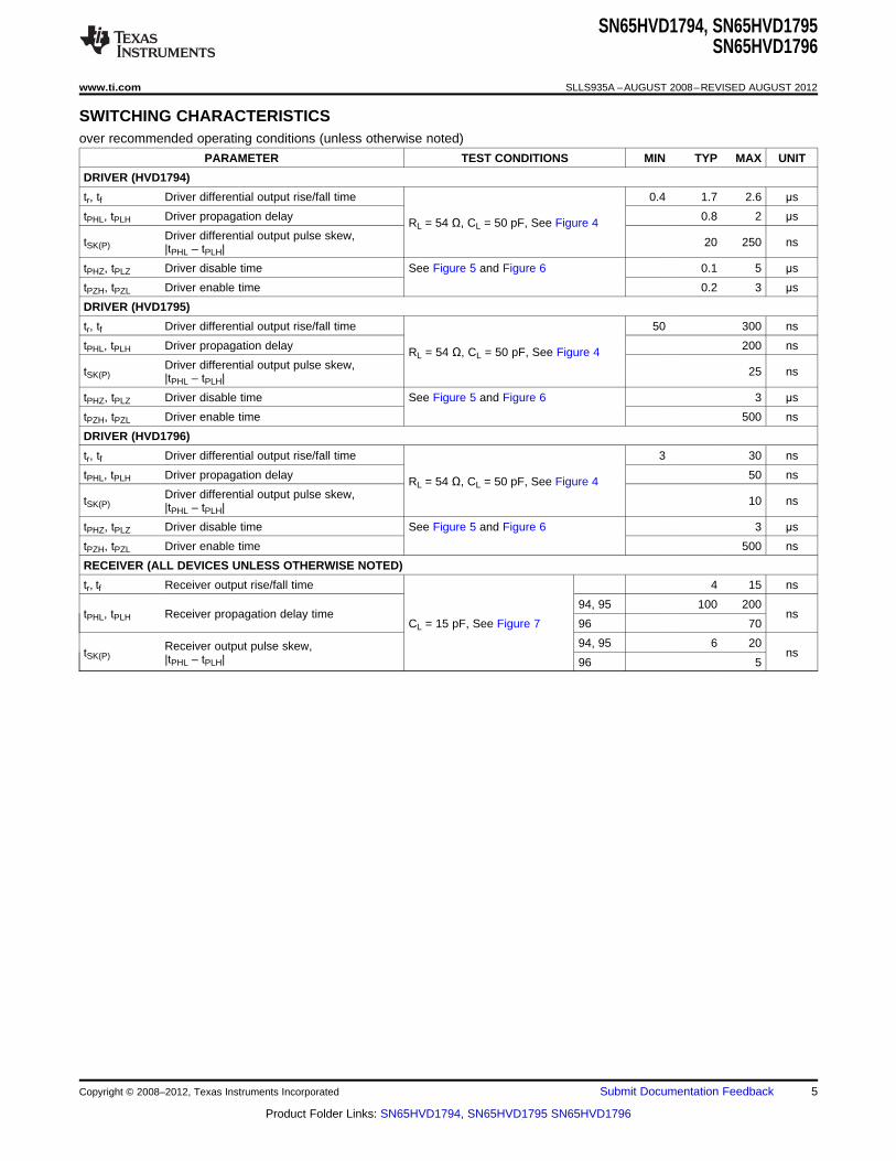
SWITCHING CHARACTERISTICSover recommended operating conditions (unless otherwise noted)
PARAMETER TEST CONDITIONS MIN TYP MAX UNIT
DRIVER (HVD1794)
tr, tf Driver differential output rise/fall time 0.4 1.7 2.6 μs
tPHL, tPLH Driver propagation delay 0.8 2 μsRL = 54 Ω, CL = 50 pF, See Figure 4Driver differential output pulse skew,tSK(P) 20 250 ns|tPHL – tPLH|
tPHZ, tPLZ Driver disable time See Figure 5 and Figure 6 0.1 5 μs
tPZH, tPZL Driver enable time 0.2 3 μs
DRIVER (HVD1795)
tr, tf Driver differential output rise/fall time 50 300 ns
tPHL, tPLH Driver propagation delay 200 nsRL = 54 Ω, CL = 50 pF, See Figure 4Driver differential output pulse skew,tSK(P) 25 ns|tPHL – tPLH|
tPHZ, tPLZ Driver disable time See Figure 5 and Figure 6 3 μs
tPZH, tPZL Driver enable time 500 ns
DRIVER (HVD1796)
tr, tf Driver differential output rise/fall time 3 30 ns
tPHL, tPLH Driver propagation delay 50 nsRL = 54 Ω, CL = 50 pF, See Figure 4Driver differential output pulse skew,tSK(P) 10 ns|tPHL – tPLH|
tPHZ, tPLZ Driver disable time See Figure 5 and Figure 6 3 μs
tPZH, tPZL Driver enable time 500 ns
RECEIVER (ALL DEVICES UNLESS OTHERWISE NOTED)
tr, tf Receiver output rise/fall time 4 15 ns
94, 95 100 200tPHL, tPLH Receiver propagation delay time ns
CL = 15 pF, See Figure 7 96 70
94, 95 6 20Receiver output pulse skew,tSK(P) ns|tPHL – tPLH| 96 5
Copyright © 2008–2012, Texas Instruments Incorporated Submit Documentation Feedback 5
Product Folder Links: SN65HVD1794, SN65HVD1795 SN65HVD1796

VOC
27 1%W ±
27 1%W ±
Input
A
B
VA
VB
VOC(PP) DVOC(SS)
VOC
C = 50 pFL ±20%
DA
B
DE
VCC
C Includes Fixture andL
Instrumentation Capacitance
S0302-01
60 1%W ±VOD0 V or 3 V
_+ –20 V < V(test) < 25 V
DE
VCC
A
B
D
375 1%W ±
375 1%W ±
S0301-01
SN65HVD1794, SN65HVD1795SN65HVD1796
SLLS935A –AUGUST 2008–REVISED AUGUST 2012 www.ti.com
THERMAL INFORMATIONPARAMETER TEST CONDITIONS VALUE UNIT
JEDEC high-K model 138SOIC-8
JEDIC low-K model 242RθJA Junction-to-ambient thermal resistance (no airflow) °C/W
JEDEC high-K model 59DIP-8
JEDIC low-K model 128
SOIC-8 62RθJB Junction-to-board thermal resistance °C/W
DIP-8 39
SOIC-8 61RθJC Junction-to-case thermal resistance °C/W
DIP-8 61
VCC = 5.5 V, TJ = 150°C, RL = 300 Ω,94 CL = 50 pF (driver), CL = 15 pF (receiver) 290
5-V supply, unterminated (1)
94 VCC = 5.5 V, TJ = 150°C, RL = 100 Ω,CL = 50 pF (driver), CL = 15 pF (receiver)
95 3205-V supply, RS-422 load (1)PD Power dissipation mW96
94 VCC = 5.5 V, TJ = 150°C, RL = 54 Ω, 400CL = 50 pF (driver), CL = 15 pF (receiver)
95 5-V supply, RS-485 load (1)
96
TSD Thermal-shutdown junction temperature 170 °C
(1) Driver enabled, 50% duty cycle square-wave signal at signaling rate: 115 kbps for HVD1794, 1 Mbps for HVD1795, 10 Mbps forHVD1796
PARAMETER MEASUREMENT INFORMATION
Input generator rate is 100 kbps, 50% duty cycle, rise and fall times less than 6 nsec, output impedance 50 Ω.
Figure 2. Measurement of Driver Differential Output Voltage With Common-Mode Load
Figure 3. Measurement of Driver Differential and Common-Mode Output With RS-485 Load
6 Submit Documentation Feedback Copyright © 2008–2012, Texas Instruments Incorporated
Product Folder Links: SN65HVD1794, SN65HVD1795 SN65HVD1796

InputGenerator 50 W
3 V VO
S1
3 V
50%
50%
50%
tPZL tPLZ
10%
» 3 V
0 V
VOL
VI
VO
R = 110L W
±1%
CL = 50 pF ±20%
C Includes FixtureL
and InstrumentationCapacitance
DA
BDE
VI
» 3 V
S0305-01
0.5 V
3 V
0 V
VOH
» 0 VtPHZ
tPZH
50% 50%VI
VO50%
90%
R = 110L W
± 1%InputGenerator
50 W
3 V
S1
C = 50 pFL ±20%
C Includes FixtureL
and InstrumentationCapacitance
DA
BDE
VO
VI
S0304-01
VOD
RL = 54
1%
W
±50 W
tPLH tPHL
50% 50%
3 V
» 2 V
» –2 V
90%
10%0 V
VI
VOD
tr tf
C = 50 pF 20%L ±
C Includes Fixture
and InstrumentationCapacitance
L
DA
B
DE
VCC
VIInput
Generator90%
0 V10%
Note: V is solid line when INV = LO,
V is dashed when INV = HII
I
SN65HVD1794, SN65HVD1795SN65HVD1796
www.ti.com SLLS935A –AUGUST 2008–REVISED AUGUST 2012
PARAMETER MEASUREMENT INFORMATION (continued)
Figure 4. Measurement of Driver Differential Output Rise and Fall Times and Propagation Delays
NOTE: D at 3 V to test non-inverting output, D at 0 V to test inverting output.
Figure 5. Measurement of Driver Enable and Disable Times With Active High Output and Pulldown Load
NOTE: D at 0 V to test non-inverting output, D at 3 V to test inverting output.
Figure 6. Measurement of Driver Enable and Disable Times With Active-Low Output and Pullup Load
Copyright © 2008–2012, Texas Instruments Incorporated Submit Documentation Feedback 7
Product Folder Links: SN65HVD1794, SN65HVD1795 SN65HVD1796

Signaling Rate − Mbps
40
60
80
100
120
0 2 4 6 8 10
I CC
− R
MS
Sup
ply
Cur
rent
− m
A
G002
TA = 25°CRE at VCCDE at VCCRL = 54 ΩCL = 50 pFVCC = 5 V
VCC − Supply Voltage − V
−10
0
10
20
30
40
50
60
70
0.0 0.6 1.2 1.8 2.4 3.0 3.6 4.2 4.8 5.4
I O −
Driv
er O
utpu
t Cur
rent
− m
A
G001
TA = 25°CDE at VCCD at VCCRL = 54 Ω
InputGenerator
50 W
VO
1.5 V C = 15 pF 20%L ±
C Includes Fixture
and InstrumentationCapacitance
L
A
BVI
R
50% 50%
3 V
VOH
VOL
50%10%
50%
tPLH tPHL
tftr
90%
VI
VO
0 V
90%
10%
Note: V is solid line when INV = LO,
V is dashed when INV = HII
I
SN65HVD1794, SN65HVD1795SN65HVD1796
SLLS935A –AUGUST 2008–REVISED AUGUST 2012 www.ti.com
PARAMETER MEASUREMENT INFORMATION (continued)
Figure 7. Measurement of Receiver Output Rise and Fall Times and Propagation Delays
TYPICAL CHARACTERISTICS
DRIVER OUTPUT CURRENT RMS SUPPLY CURRENTvs vs
SUPPLY VOLTAGE SIGNALING RATE
Figure 8. Figure 9.
8 Submit Documentation Feedback Copyright © 2008–2012, Texas Instruments Incorporated
Product Folder Links: SN65HVD1794, SN65HVD1795 SN65HVD1796

00.2
0.4
0.60.8
1
1.2
1.4
1.6
1.8
2
2.2
2.4
2.6
2.8
3
3.2
3.4
3.6
3.84
4.2
4.4
0 2 4 6 8 10 12 14 16 18 20 22 24 26 28 30 32 34 36 38 40 42 44 46 48 50
Idiff - Differential Load Current - mA
V = 5.5 VCC
Load = 300 W Load = 100 W
Load = 60 W
VO
D -
Dif
fere
nti
al O
utp
ut
Vo
ltag
e -
V
V = 5 VCC
V = 4.5 VCC
VIN − Bus Pin Voltage − V
−2.0
−1.5
−1.0
−0.5
0.0
0.5
1.0
1.5
2.0
−90 −60 −30 0 30 60 90
I IN −
Bus
Pin
Cur
rent
− m
A
G004
SN65HVD1794, SN65HVD1795SN65HVD1796
www.ti.com SLLS935A –AUGUST 2008–REVISED AUGUST 2012
TYPICAL CHARACTERISTICS (continued)BUS PIN CURRENT
vsBUS PIN VOLTAGE
Figure 10.
DIFFERENTIAL OUTPUT VOLTAGEvs
DIFFERENTIAL LOAD CURRENT
Figure 11.
Copyright © 2008–2012, Texas Instruments Incorporated Submit Documentation Feedback 9
Product Folder Links: SN65HVD1794, SN65HVD1795 SN65HVD1796

2
3
8
6
5
7
A
Z
Y
B
R
D
S0310-01
1
2
3
4
8
7
6
5
VCC
R
D
GND
A
B
Z
Y
PW Package(Top View)
P0074-01
S0309-01
1
2
3
4
6
7
A
B
R
RE
DE
D
R
RE
DE
D
VCC
B
A
GND
D Package(Top View)
1
2
3
4
8
7
6
5
P0066-03
SN65HVD1794, SN65HVD1795SN65HVD1796
SLLS935A –AUGUST 2008–REVISED AUGUST 2012 www.ti.com
ADDITIONAL OPTIONS
The SN65HVD17xx family also has options for J1708 applications, for always-enabled full-duplex versions(industry-standard SN65LBC179 footprint) and for inverting-polarity versions, which allow users to correct areversal of the bus wires without re-wiring. Contact your local Texas Instruments representative for informationon these options.
PART NUMBER SN65HVD17xx
FOOTPRINT/FUNCTION SLOW MEDIUM FAST
Half-duplex (176 pinout) 85 86 87
Full-duplex no enables (179 pinout) 88 89 90
Full-duplex with enables (180 pinout) 91 92 93
Half-duplex with cable invert 94 95 96
Full-duplex with cable invert and enables 97 98 99
J1708 08 09 10
Figure 12. SN65HVD1708E Transceiver for J1708 Applications
Figure 13. SN65HVD17xx Always-Enabled Driver Receiver
10 Submit Documentation Feedback Copyright © 2008–2012, Texas Instruments Incorporated
Product Folder Links: SN65HVD1794, SN65HVD1795 SN65HVD1796
SN65HVD1794, SN65HVD1795SN65HVD1796
www.ti.com SLLS935A –AUGUST 2008–REVISED AUGUST 2012
APPLICATION INFORMATION
Hot-Plugging
These devices are designed to operate in "hot swap" or "hot pluggable" applications. Key features for hot-pluggable applications are power-up, power-down glitch free operation, default disabled input/output pins, andreceiver failsafe. As shown in Figure 8, an internal Power-On Reset circuit keeps the driver outputs in a high-impedance state until the supply voltage has reached a level at which the device will reliably operate. Thisensures that no spurious transitions (glitches) will occur on the bus pin outputs as the power supply turns on orturns off.
As shown in the device FUNCTION TABLE, the ENABLE inputs have the feature of default disable on both thedriver enable and receiver enable. This ensures that the device will neither drive the bus nor report data on the Rpin until the associated controller actively drives the enable pins.
Likewise, the receiver output is "failsafe" to open-circuit, short-circuit, or idle (terminated only) bus conditions.This eliminates false transitions on the receiver output until a valid RS-485 signal is applied to the receiver inputpins.
Cable Invert
For many RS-485 applications, wiring of data cables takes place during equipment installation, and the possibilityof miss-wiring is a significant issue. When the twisted-pair wires are reversed due to installation mistakes, normalRS-485 communication is not possible. The Cable Invert (INV) pin allows designers to compensate for thisinstallation mistake. Under normal circumstances, the INV pin can be set to logic LOW, and the transceiveroperates with normal polarity. If, after initial network start-up, a node cannot communicate properly, the localcontroller can set the INV pin high, which will invert the polarity of the A and B differential bus pins. This willcompensate for a reversal of the bus wires, allowing proper communication.
Receiver Failsafe
The differential receiver is “failsafe” to invalid bus states caused by open bus conditions such as a disconnectedconnector, shorted bus conditions such as cable damage shorting the twisted-pair together or idle bus conditionsthat occur when no driver is actively driving a valid RS-485 bus state on the network. In any of these cases, thedifferential receiver outputs a failsafe state, so that small noise signals do not cause spurious transitions at thereceiver output. When INV is logic Low or Open (normal operation), the receiver output will be failsafe High.When INV is logic High to correct for a twisted-pair reversal, the receiver output will be failsafe Low under thosefault conditions.
Copyright © 2008–2012, Texas Instruments Incorporated Submit Documentation Feedback 11
Product Folder Links: SN65HVD1794, SN65HVD1795 SN65HVD1796

SN65HVD1794, SN65HVD1795SN65HVD1796
SLLS935A –AUGUST 2008–REVISED AUGUST 2012 www.ti.com
Changes from Original (August 2008) to Revision A Page
• Added Voltage range across A and B pins (differential) in Absolute Maximum Ratings table ............................................. 3
12 Submit Documentation Feedback Copyright © 2008–2012, Texas Instruments Incorporated
Product Folder Links: SN65HVD1794, SN65HVD1795 SN65HVD1796

TAPE AND REEL INFORMATION
*All dimensions are nominal
Device PackageType
PackageDrawing
Pins SPQ ReelDiameter
(mm)
ReelWidth
W1 (mm)
A0(mm)
B0(mm)
K0(mm)
P1(mm)
W(mm)
Pin1Quadrant
SN65HVD1794DR SOIC D 8 2500 330.0 12.4 6.4 5.2 2.1 8.0 12.0 Q1
PACKAGE MATERIALS INFORMATION
www.ti.com 26-Jan-2013
Pack Materials-Page 1

*All dimensions are nominal
Device Package Type Package Drawing Pins SPQ Length (mm) Width (mm) Height (mm)
SN65HVD1794DR SOIC D 8 2500 367.0 367.0 35.0
PACKAGE MATERIALS INFORMATION
www.ti.com 26-Jan-2013
Pack Materials-Page 2


IMPORTANT NOTICE
Texas Instruments Incorporated and its subsidiaries (TI) reserve the right to make corrections, enhancements, improvements and otherchanges to its semiconductor products and services per JESD46, latest issue, and to discontinue any product or service per JESD48, latestissue. Buyers should obtain the latest relevant information before placing orders and should verify that such information is current andcomplete. All semiconductor products (also referred to herein as “components”) are sold subject to TI’s terms and conditions of salesupplied at the time of order acknowledgment.
TI warrants performance of its components to the specifications applicable at the time of sale, in accordance with the warranty in TI’s termsand conditions of sale of semiconductor products. Testing and other quality control techniques are used to the extent TI deems necessaryto support this warranty. Except where mandated by applicable law, testing of all parameters of each component is not necessarilyperformed.
TI assumes no liability for applications assistance or the design of Buyers’ products. Buyers are responsible for their products andapplications using TI components. To minimize the risks associated with Buyers’ products and applications, Buyers should provideadequate design and operating safeguards.
TI does not warrant or represent that any license, either express or implied, is granted under any patent right, copyright, mask work right, orother intellectual property right relating to any combination, machine, or process in which TI components or services are used. Informationpublished by TI regarding third-party products or services does not constitute a license to use such products or services or a warranty orendorsement thereof. Use of such information may require a license from a third party under the patents or other intellectual property of thethird party, or a license from TI under the patents or other intellectual property of TI.
Reproduction of significant portions of TI information in TI data books or data sheets is permissible only if reproduction is without alterationand is accompanied by all associated warranties, conditions, limitations, and notices. TI is not responsible or liable for such altereddocumentation. Information of third parties may be subject to additional restrictions.
Resale of TI components or services with statements different from or beyond the parameters stated by TI for that component or servicevoids all express and any implied warranties for the associated TI component or service and is an unfair and deceptive business practice.TI is not responsible or liable for any such statements.
Buyer acknowledges and agrees that it is solely responsible for compliance with all legal, regulatory and safety-related requirementsconcerning its products, and any use of TI components in its applications, notwithstanding any applications-related information or supportthat may be provided by TI. Buyer represents and agrees that it has all the necessary expertise to create and implement safeguards whichanticipate dangerous consequences of failures, monitor failures and their consequences, lessen the likelihood of failures that might causeharm and take appropriate remedial actions. Buyer will fully indemnify TI and its representatives against any damages arising out of the useof any TI components in safety-critical applications.
In some cases, TI components may be promoted specifically to facilitate safety-related applications. With such components, TI’s goal is tohelp enable customers to design and create their own end-product solutions that meet applicable functional safety standards andrequirements. Nonetheless, such components are subject to these terms.
No TI components are authorized for use in FDA Class III (or similar life-critical medical equipment) unless authorized officers of the partieshave executed a special agreement specifically governing such use.
Only those TI components which TI has specifically designated as military grade or “enhanced plastic” are designed and intended for use inmilitary/aerospace applications or environments. Buyer acknowledges and agrees that any military or aerospace use of TI componentswhich have not been so designated is solely at the Buyer's risk, and that Buyer is solely responsible for compliance with all legal andregulatory requirements in connection with such use.
TI has specifically designated certain components as meeting ISO/TS16949 requirements, mainly for automotive use. In any case of use ofnon-designated products, TI will not be responsible for any failure to meet ISO/TS16949.
Products Applications
Audio www.ti.com/audio Automotive and Transportation www.ti.com/automotive
Amplifiers amplifier.ti.com Communications and Telecom www.ti.com/communications
Data Converters dataconverter.ti.com Computers and Peripherals www.ti.com/computers
DLP® Products www.dlp.com Consumer Electronics www.ti.com/consumer-apps
DSP dsp.ti.com Energy and Lighting www.ti.com/energy
Clocks and Timers www.ti.com/clocks Industrial www.ti.com/industrial
Interface interface.ti.com Medical www.ti.com/medical
Logic logic.ti.com Security www.ti.com/security
Power Mgmt power.ti.com Space, Avionics and Defense www.ti.com/space-avionics-defense
Microcontrollers microcontroller.ti.com Video and Imaging www.ti.com/video
RFID www.ti-rfid.com
OMAP Applications Processors www.ti.com/omap TI E2E Community e2e.ti.com
Wireless Connectivity www.ti.com/wirelessconnectivity
Mailing Address: Texas Instruments, Post Office Box 655303, Dallas, Texas 75265Copyright © 2013, Texas Instruments Incorporated