Embed Size (px)
Citation preview

HIT-HY 70 Hybrid Adhesive for Masonry
Flexible, strong and reliable.
Hilti. Outperform. Outlast.
Hilti Adhesive Anchor
2 Hilti, Inc. (USA) 1-800-879-8000 I www.us.hilti.com I en español 1-800-879-5000 I Hilti (Canada) Corp. 1-800-363-4458 I www.hilti.ca I HIT-HY 70 Submittal Information 08/13
Flexible, strong and reliable.HIT-HY 70 Masonry Adhesive Anchoring System Life just got easier with one adhesive anchoring product to solve all your masonry needs. The new Hilti HIT-HY 70 Masonry Adhesive Anchoring System works in a variety of masonry base materials: grout-filled CMU, hollow CMU, solid brick, hollow brick, multi-wythe solid brick walls. The improved formula and innovative composite sleeve design provides strong, reliable and easy to install fastenings.
Applications
• Retrofitsofhistoricmasonrybuildings, including seismic retrofitofmulti-wythewalls
• Sign,fenceorawningattachmentto masonry wall or façade
• Façadetie-backstomasonrystructural wall
• Scaffoldingattachmenttomasonry structure
• Pipe,cabletray,fixturefasteningto masonry base material
Outperform and Outlast
• Curesin~30minutesat70°Fproviding quick installation times tofinishthejobearlier
• Achievevariousembedmentdepths by combining mesh sleeves to custom lengths
Technical Data HIT-HY 70Product Hybrid Urethane Methacrylate
Base material temperature (grout-filled and hollow CMU) 23°Fto104°F(-5°Cto40°C)
Base material temperature (hollow brick, solid brick, and multi-wythe solid brick)
41°Fto104°F(5°Cto40°C)
Diameter range 1/4"to3/4"
Listings/Approvals •ICC-ES(InternationalCodeCouncil)-ESR-2682forHollowMasonry,GroutedMasonryandHollowBrick -ESR-3342forUn-ReinforcedMasonry(URM)
Package volume •VolumeofHIT-HY7011.1floz/330mlfoilpackis20.1in3 •VolumeofHIT-HY7016.9floz/500mlfoilpackis30.5in3
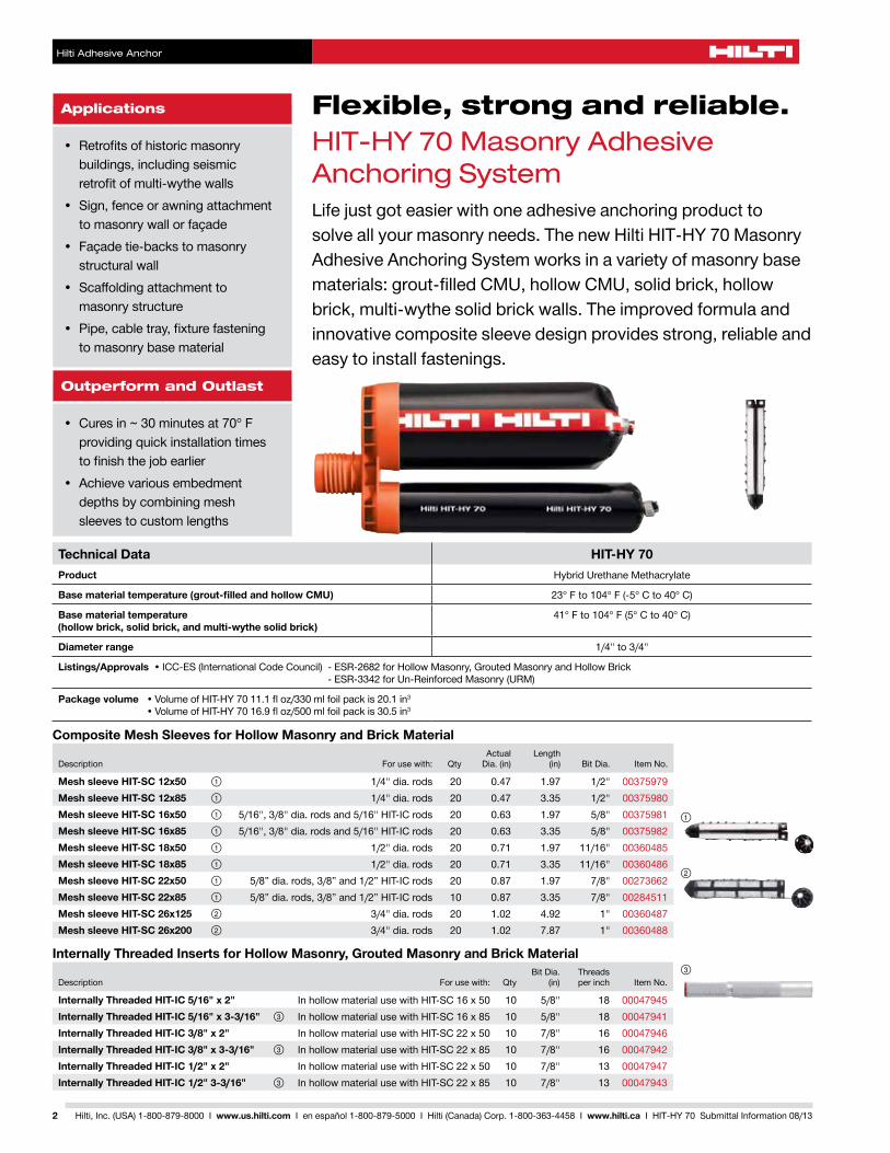
Composite Mesh Sleeves for Hollow Masonry and Brick Material
Description Forusewith: QtyActual Dia.(in)
Length (in) BitDia. Item No.
Mesh sleeve HIT-SC 12x50 ① 1/4"dia.rods 20 0.47 1.97 1/2" 00375979Mesh sleeve HIT-SC 12x85 ① 1/4"dia.rods 20 0.47 3.35 1/2" 00375980Mesh sleeve HIT-SC 16x50 ① 5/16",3/8"dia.rodsand5/16"HIT-ICrods 20 0.63 1.97 5/8" 00375981Mesh sleeve HIT-SC 16x85 ① 5/16",3/8"dia.rodsand5/16"HIT-ICrods 20 0.63 3.35 5/8" 00375982Mesh sleeve HIT-SC 18x50 ① 1/2"dia.rods 20 0.71 1.97 11/16" 00360485Mesh sleeve HIT-SC 18x85 ① 1/2"dia.rods 20 0.71 3.35 11/16" 00360486Mesh sleeve HIT-SC 22x50 ① 5/8”dia.rods,3/8”and1/2”HIT-ICrods 20 0.87 1.97 7/8" 00273662Mesh sleeve HIT-SC 22x85 ① 5/8”dia.rods,3/8”and1/2”HIT-ICrods 10 0.87 3.35 7/8" 00284511Mesh sleeve HIT-SC 26x125 ② 3/4"dia.rods 20 1.02 4.92 1" 00360487Mesh sleeve HIT-SC 26x200 ② 3/4"dia.rods 20 1.02 7.87 1" 00360488
Internally Threaded Inserts for Hollow Masonry, Grouted Masonry and Brick Material
Description Forusewith: QtyBitDia.
(in)Threads per inch Item No.
Internally Threaded HIT-IC 5/16" x 2" InhollowmaterialusewithHIT-SC16x50 10 5/8" 18 00047945Internally Threaded HIT-IC 5/16" x 3-3/16" ③ InhollowmaterialusewithHIT-SC16x85 10 5/8" 18 00047941Internally Threaded HIT-IC 3/8" x 2" InhollowmaterialusewithHIT-SC22x50 10 7/8" 16 00047946Internally Threaded HIT-IC 3/8" x 3-3/16" ③ InhollowmaterialusewithHIT-SC22x85 10 7/8" 16 00047942Internally Threaded HIT-IC 1/2" x 2" InhollowmaterialusewithHIT-SC22x50 10 7/8" 13 00047947Internally Threaded HIT-IC 1/2" 3-3/16" ③ InhollowmaterialusewithHIT-SC22x85 10 7/8" 13 00047943
③
②
①
HIT-HY 70 Hybrid Adhesive for Masonry Construction
Hilti Adhesive Anchor
3Hilti, Inc. (USA) 1-800-879-8000 I www.us.hilti.com I en español 1-800-879-5000 I Hilti (Canada) Corp. 1-800-363-4458 I www.hilti.ca I HIT-HY 70 Submittal Information 08/13
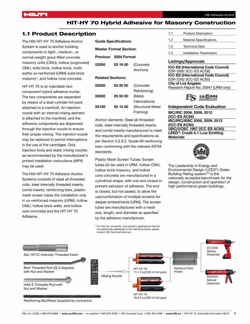
ED3500 BatteryDispenser
MD2500ManualDispenser
Std. HIT-IC Internally Threaded Insert
BentThreadedRod(22.5degrees)with Nut and Washer
HAS-EThreadedRodwith Nut and Washer
ReinforcingBar/Rebar(suppliedbycontractor)
MixingNozzle
HIT-HY 70 11.1floz/330mlfoilpack
HIT-HY 70 16.9floz/500mlfoilpack
AdhesivePackHolder
1.1 Product DescriptionThe Hilti HIT-HY 70 Adhesive Anchor System is used to anchor building components to light-, medium-, or normal-weight grout-filled concrete masonryunits(CMU),hollow(ungrouted)CMU, solid brick, hollow brick, multi-wytheun-reinforced(URM)solidbrickmasonry*, and hollow core concrete.
HIT-HY 70 is an injectable two-component hybrid adhesive mortar. The two components are separated by means of a dual-cylinder foil pack attached to a manifold. An injection nozzlewithaninternalmixingelementis attached to the manifold, and the adhesive components are dispensed throughtheinjectionnozzletoensuretheirpropermixing.Theinjectionnozzlemay be replaced to permit interruptions in the use of the cartridges. Only injectiontoolsandstaticmixingnozzlesas recommended by the manufacturer’s printedinstallationinstructions(MPII)may be used.
The Hilti HIT-HY 70 Adhesive Anchor Systems consists of steel all-threaded rods, steel internally threaded inserts, combi inserts, reinforcing bars, plastic-meshscreentubes(forinstallationonlyinun-reinforcedmasonry(URM),hollowCMU, hollow brick walls, and hollow coreconcrete)andtheHIT-HY70Adhesive.
Guide Specifications
Master Format Section:
Previous 2004 Format
03250 03 16 00 (Concrete Anchors)
Related Sections:
03200 03 20 00 (Concrete Reinforcing) 05050 05 50 00 (Metal Fabrications) 05120 05 10 00 (StructuralMetal Framing)
Anchor elements: Steel all-threaded rods, steel internally threaded inserts, and combi inserts manufactured to meet the requirements and specifications as perSection3.2.9.2.Grade60reinforcingbars conforming with the relevant ASTM standards.
PlasticMeshScreenTubes:Screentubes(tobeusedinURM,hollowCMU,hollow brick masonry, and hollow coreconcrete)aremanufacturedinacylindrical shape, with one end closed to preventextrusionofadhesive.Theendis closed, but not sealed, to allow the use/combinationofmultiplescreensfordeeperembedments(URM).Thescreentubes are manufactured with a mesh size,length,anddiameterasspecifiedby the adhesive manufacturer.
*Forclaytile,terracotta,andmasonryapplicationsthatarenotspecificallyaddressedinthisTechnicalGuide,pleasecontact Hilti Technical Services.
1.1 ProductDescription
1.2 MaterialSpecifications
1.3 TechnicalData
1.4 InstallationParameters
Listings/ApprovalsICC-ES (International Code Council)ESR-2682(ICC-ESAC58)ICC-ES (International Code Council)ESR-3342(ICC-ESAC60)City of Los AngelesResearchReportNo.25947(URMonly)
Independent Code EvaluationIBC/IRC 2006, 2009, 2012 (ICC-ES AC58)IBC/IRC/IEBC 2006, 2009, 2012 (ICC-ES AC60)UBC/UCBC 1997 (ICC-ES AC60)LEED®: Credit 4.1-Low Emitting Materials
TheLeadershipinEnergyandEnvironmentalDesign(LEED® )GreenBuildingRatingsystemTM is the nationally accepted benchmark for the design, construction and operation of high performance green buildings.
Hilti Adhesive Anchor
1.2 Material Specifications
4 Hilti, Inc. (USA) 1-800-879-8000 I www.us.hilti.com I en español 1-800-879-5000 I Hilti (Canada) Corp. 1-800-363-4458 I www.hilti.ca I HIT-HY 70 Submittal Information 08/13
Material Properties for HIT-HY 70 — Cured Adhesive
Compressive Strength ASTMD695/DIN53454 7,252-10,153psi 50-70MPaModulusofelasticity(Compressiontest) ASTMD790/DIN53452 246,568psi 1,700MPa
Water Absorption ASTMD570/DIN53495 3-8% 3-8%ElectricalResistance VDE/DIN0303T3 2.705-1012ohm/in. 1.065-1012ohm/cm
Material Specifications
Mechanical Properties
fy min. fu
ksi(MPa) ksi(MPa)StandardHAS-ErodmaterialmeetstherequirementsofISO898Class5.8 58 (400) 72.5 (500)HighStrengthor“SuperHAS”rodmaterialmeetstherequirementsofASTMA193,GradeB7 105 (724) 125 (862)StainlessHASrodmaterialmeetstherequirementsofASTMF593(AISI304/316)ConditionCW3/8"to5/8"
65 (448) 100 (689)
StainlessHASrodmaterialmeetstherequirementsofASTMF593(AISI304/316)ConditionCW3/4" 45 (310) 85 (586)CarbonSteelHIS-NInsertconfirmingtoDIN10277-3 54.4 (375) 66.7 (460)StainlessSteelHIS-RNInsertconformingtoDIN10088-3 50.8 (350) 101.5 (700)CarbonSteelHIT-ICInsertconformingtoDIN10277-3 54.4 (375) 66.7 (460)HASSuperandHAS-EStandardNutMaterialmeetstherequirementsofSAEJ995Grade5HASStainlessSteelNutmaterialmeetstherequirementsofASTMF594HAS-ECarbonSteelandStainlessSteelWashersmeetdimensionalrequirementsofANSIB18.22.1TypeAPlainHASStainlessSteelWashersmeettherequirementsofAISI304orAISI316conformingtoASTMA240HASSuperandHAS-EStandardWashersmeettherequirementsofASTMF884,HVAllHAS-EandHASSuperRodsandHAS-EStandard,HIS-Ninserts,nutsandwashersarezincplatedto ASTMB633SC1Note: Special Order steel rod material may vary from standard materials.
1.3 Technical Data
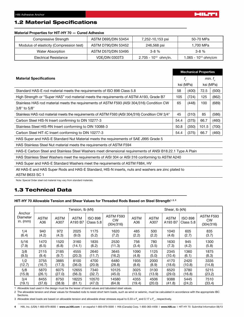
HIT-HY 70 Allowable Tension and Shear Values for Threaded Rods Based on Steel Strength1, 2, 3
AnchorDiameterin.(mm)
Tension,lb(kN) Shear,lb(kN)
ASTMA36
ASTMA307
ASTMA193B7
ISO898Class5.8
ASTMF593CW
(304/316)ASTMA36
ASTM A307
ASTM A193B7
ISO898Class5.8
ASTMF593CW
(304/316)
1/4(6.4)
940(4.2)
972(4.3)
2025(9.0)
1175(5.2)
1620(7.2)
485(2.2)
500(2.2)
1040(4.6)
605(2.7)
835(3.7)
5/16(7.9)
1470(6.5)
1520(6.8)
3160(14.1)
1835(8.2)
2530(11.3)
756(3.4)
780(3.5)
1630(7.3)
945(4.2)
1300(5.8)
3/8(9.5)
2115(9.4)
2185(9.7)
4555(20.3)
2640(11.7)
3645(16.2)
1090(4.8)
1125(5.0)
2345(10.4)
1360(6.1)
1875(8.3)
1/2(12.7)
3755(16.7)
3885(17.3)
8100(36.0)
4700(20.9)
6480(28.8)
1935(8.6)
2000(8.9)
4170(18.6)
2420(10.8)
3335(14.8)
5/8(15.9)
5870(26.1)
6075(27.0)
12655(56.3)
7340(32.7)
10125(45.0)
3025(13.5)
3130(13.9)
6520(29.0)
3780(16.8)
5215(23.2)
3/4(19.1)
8455(37.6)
8750(38.9)
18225(81.1)
10570(47.0)
14580(64.9)
4355(19.4)
4506(20.0)
9388(41.8)
5445(24.2)
7510(33.4)
1Allowableloadusedinthedesignmustbethelesserofbondvaluesandtabulatedsteelvalues.2Theallowabletensionandshearvaluesforthreadedrodstoresistshorttermloads,suchaswindorseismic,mustbecalculatedinaccordancewiththeappropriateIBC
Sections.3Allowablesteelloadsarebasedonallowabletensionandallowableshearstressesequalto0.33xFuand0.17xFu , respectively.
1.3 Technical Data
Hilti Adhesive Anchor
5Hilti, Inc. (USA) 1-800-879-8000 I www.us.hilti.com I en español 1-800-879-5000 I Hilti (Canada) Corp. 1-800-363-4458 I www.hilti.ca I HIT-HY 70 Submittal Information 08/13
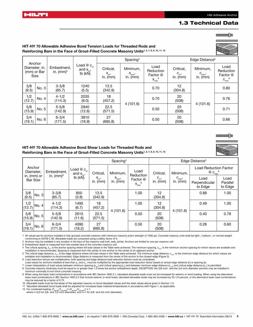
1Allvaluesareforanchorsinstalledinfullygroutedconcretemasonrywithminimummasonryprismstrengthof1500psi.Concretemasonryunitsshallbelight-,medium-,ornormal-weightconformingtoASTMC90.Allowableloadsarecomputedusingasafetyfactorof5.
2Anchorsmaybeinstalledinanylocationinthefaceofthemasonrywall(cell,web,joints).Anchorsarelimitedtoonepermasonrycell.3Embedmentdepthismeasuredfromtheoutsidefaceoftheconcretemasonryunit.4Thecriticalspacing,scr, is the anchor spacing where full load values in the Table were achieved. The minimum spacing, smin, is the minimum anchor spacing for which values are available and
installation is recommended. Spacing is measured from the center of one anchor to the center of an adjacent anchor.5Thecriticaledgedistance,ccr, is the edge distance where full load values in the Table were achieved. The minimum edge distance, cmin, is the minimum edge distance for which values are availableandinstallationisrecommended.Edgedistanceismeasuredfromthecenteroftheanchortotheclosestedge(Figure2).
6Loadreductionfactorsaremultiplicative,bothspacingandedgedistanceloadreductionfactorsmustbeconsidered. Load values for anchors installed at less than scr and ccrmustbemultipliedbytheappropriateloadreductionfactorbasedonactualedgedistance(c)orspacing(s).
7Linearinterpolationofloadvaluesbetweenminimumspacing(smin)andcriticalspacing(scr)andbetweenminimumedgedistance(cmin)andcriticaledgedistance(ccr)ispermitted.8Concretemasonrythicknessmustbeequaltoorgreaterthan1.5timestheanchorembedmentdepth.EXCEPTION:the5/8-inch-andthe3/4-inch-diameteranchorsmaybeinstalledinminimumnominally8-inch-thickconcretemasonry.
9WhenusingthebasicloadcombinationsinaccordancewithIBCSection1605.3.1,tabulatedallowableloadsmustnotbeincreasedforseismicorwindloading.WhenusingthealternativebasicloadcombinationsinIBCSection1605.3.2thatincludeseismicorwindloads,tabulatedallowableloadsmaybeincreasedby33-1/3percent,orthealternativebasicloadcombinationsmaybereducedbyafactorof0.75.
10AllowableloadsmustbethelesseroftheadjustedmasonryorbondtabulatedvaluesandthesteelvaluesabovegiveninSection1.3.11TabulatedallowablebondloadsshallbeadjustedforincreasedbasematerialtemperaturesinaccordancewithFigure1,asapplicable.12Forcombinedloading:(Tapplied/Tallowable)n+(Vapplied/Vallowable)n≤1
wheren=5/3for3/8-and1/2-inchdiameters,andn=1for5/8-and3/4-inchdiameters.
HIT-HY 70 Allowable Adhesive Bond Tension Loads for Threaded Rods and Reinforcing Bars in the Face of Grout-Filled Concrete Masonry Units1, 2, 7, 8, 9, 10, 11, 12
AnchorDiameter, in. (mm)orBar
Size
Embedment,in.(mm)3
Load @ ccr and scr, lb(kN)
Spacing4 EdgeDistance5
Critical, scr,
in.(mm)
Minimum, smin,
in.(mm)
Load ReductionFactor@
smin6
Critical, ccr,
in.(mm)
Minimum, cmin,
in.(mm)
Load ReductionFactor@
cmin6
3/8(9.5) No.3 3-3/8
(85.7)1240(5.5)
13.5(342.9)
4(101.6)
0.70 12(304.8)
4(101.6)
0.80
1/2(12.7) No.4 4-1/2
(114.3)2035(9.0)
18(457.2) 0.70 20
(508) 0.76
5/8(15.9) No.5 5-5/8
(142.9)2840(12.6)
22.5(571.5) 0.50 20
(508) 0.71
3/4(19.1) No.6 6-3/4
(171.5)3810(16.9)
27(685.8) 0.50 20
(508) 0.66
HIT-HY 70 Allowable Adhesive Bond Shear Loads for Threaded Rods and Reinforcing Bars in the Face of Grout-Filled Concrete Masonry Units1, 2, 7, 8, 9, 10, 11, 12
AnchorDiameter, in.(mm)orBarSize
Embedment,in.(mm)3
Load @ ccr and scr, lb(kN)
Spacing4 EdgeDistance5
Critical, scr,
in.(mm)
Minimum, smin,
in.(mm)
Load ReductionFactor@
smin6
Critical, ccr,
in.(mm)
Minimum, cmin,
in.(mm)
LoadReductionFactor @ cmin
6
Load Perpendicular
toEdge
Load Parallel toEdge
3/8(9.5) No.3
3-3/8(85.7)
850(3.8)
13.5(342.9)
4(101.6)
1.00 12(304.8)
4(101.6)
0.88 1.00
1/2(12.7) No.4
4-1/2(114.3)
1495(6.7)
18(457.2)
1.00 12(304.8)
0.49 1.00
5/8(15.9) No.5
5-5/8(142.9)
2615(11.6)
22.5(571.5)
0.50 20(508)
0.40 0.78
3/4(19.1) No.6
6-3/4(171.5)
4090(18.2)
27(685.8)
0.50 20(508)
0.26 0.60
Hilti Adhesive Anchor
1.3 Technical Data
6 Hilti, Inc. (USA) 1-800-879-8000 I www.us.hilti.com I en español 1-800-879-5000 I Hilti (Canada) Corp. 1-800-363-4458 I www.hilti.ca I HIT-HY 70 Submittal Information 08/13
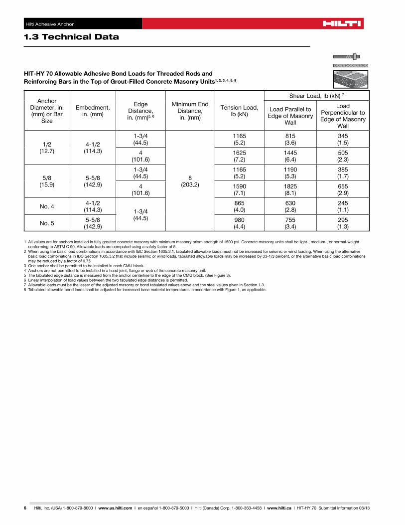
1Allvaluesareforanchorsinstalledinfullygroutedconcretemasonrywithminimummasonryprismstrengthof1500psi.Concretemasonryunitsshallbelight-,medium-,ornormal-weightconformingtoASTMC90.Allowableloadsarecomputedusingasafetyfactorof5.
2WhenusingthebasicloadcombinationsinaccordancewithIBCSection1605.3.1,tabulatedallowableloadsmustnotbeincreasedforseismicorwindloading.WhenusingthealternativebasicloadcombinationsinIBCSection1605.3.2thatincludeseismicorwindloads,tabulatedallowableloadsmaybeincreasedby33-1/3percent,orthealternativebasicloadcombinationsmaybereducedbyafactorof0.75.
3OneanchorshallbepermittedtobeinstalledineachCMUblock.4Anchorsarenotpermittedtobeinstalledinaheadjoint,flangeorweboftheconcretemasonryunit.5ThetabulatededgedistanceismeasuredfromtheanchorcenterlinetotheedgeoftheCMUblock.(SeeFigure3).6Linearinterpolationofloadvaluesbetweenthetwotabulatededgedistancesispermitted.7AllowableloadsmustbethelesseroftheadjustedmasonryorbondtabulatedvaluesaboveandthesteelvaluesgiveninSection1.3.8TabulatedallowablebondloadsshallbeadjustedforincreasedbasematerialtemperaturesinaccordancewithFigure1,asapplicable.
HIT-HY 70 Allowable Adhesive Bond Loads for Threaded Rods and Reinforcing Bars in the Top of Grout-Filled Concrete Masonry Units1, 2, 3, 4, 8, 9
AnchorDiameter, in. (mm)orBar
Size
Embedment, in.(mm)
Edge Distance,
in.(mm)5,6
MinimumEndDistance, in.(mm)
Tension Load, lb(kN)
ShearLoad,lb(kN)7
LoadParalleltoEdgeofMasonry
Wall
Load PerpendiculartoEdgeofMasonry
Wall
1/2(12.7)
4-1/2(114.3)
1-3/4(44.5)
8(203.2)
1165(5.2)
815(3.6)
345(1.5)
4(101.6)
1625(7.2)
1445(6.4)
505(2.3)
5/8(15.9)
5-5/8(142.9)
1-3/4(44.5)
1165(5.2)
1190(5.3)
385(1.7)
4(101.6)
1590(7.1)
1825(8.1)
655(2.9)
No.4 4-1/2(114.3) 1-3/4
(44.5)
865(4.0)
630(2.8)
245(1.1)
No.5 5-5/8(142.9)
980(4.4)
755(3.4)
295(1.3)
1.3 Technical Data
Hilti Adhesive Anchor
7Hilti, Inc. (USA) 1-800-879-8000 I www.us.hilti.com I en español 1-800-879-5000 I Hilti (Canada) Corp. 1-800-363-4458 I www.hilti.ca I HIT-HY 70 Submittal Information 08/13
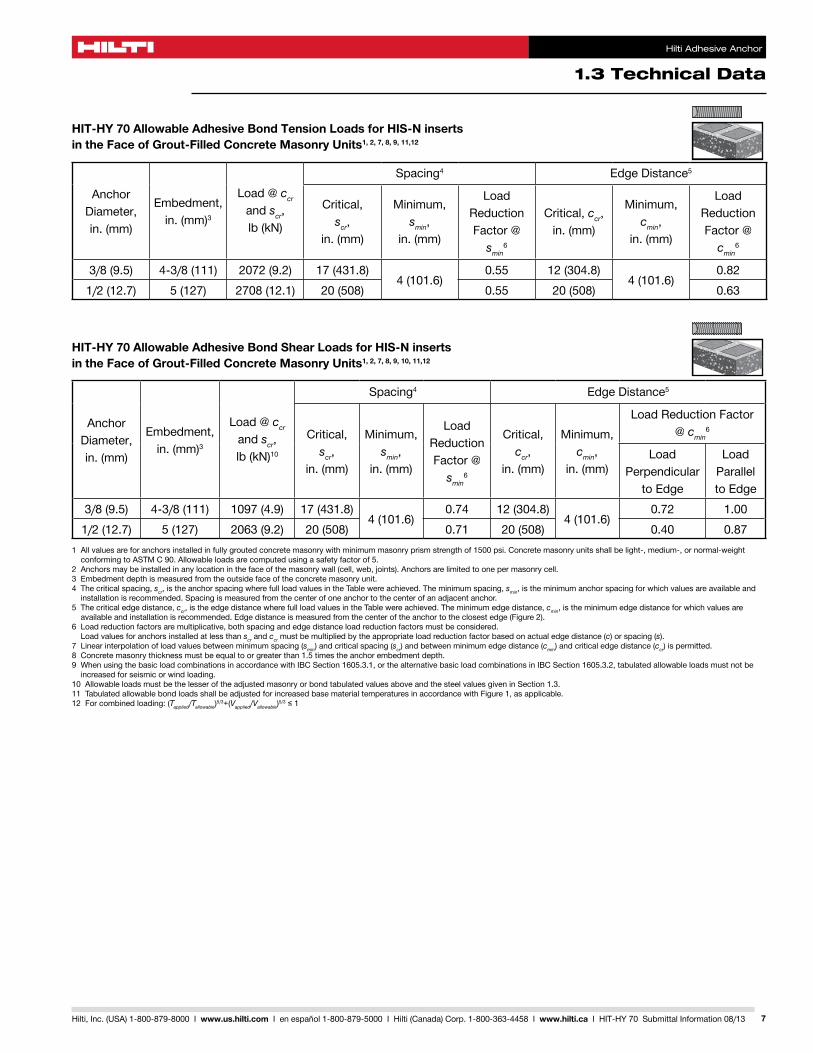
HIT-HY 70 Allowable Adhesive Bond Tension Loads for HIS-N inserts in the Face of Grout-Filled Concrete Masonry Units1, 2, 7, 8, 9, 11,12
Anchor Diameter, in.(mm)
Embedment, in.(mm)3
Load @ ccr and scr, lb(kN)
Spacing4 EdgeDistance5
Critical, scr,
in.(mm)
Minimum, smin,
in.(mm)
Load ReductionFactor@
smin6
Critical, ccr, in.(mm)
Minimum, cmin,
in.(mm)
Load ReductionFactor@
cmin6
3/8(9.5) 4-3/8(111) 2072(9.2) 17(431.8)4(101.6)
0.55 12(304.8)4(101.6)
0.821/2(12.7) 5(127) 2708(12.1) 20(508) 0.55 20(508) 0.63
HIT-HY 70 Allowable Adhesive Bond Shear Loads for HIS-N inserts in the Face of Grout-Filled Concrete Masonry Units1, 2, 7, 8, 9, 10, 11,12
Anchor Diameter, in.(mm)
Embedment, in.(mm)3
Load @ ccr and scr, lb(kN)10
Spacing4 EdgeDistance5
Critical, scr,
in.(mm)
Minimum, smin,
in.(mm)
Load ReductionFactor@
smin6
Critical, ccr,
in.(mm)
Minimum, cmin,
in.(mm)
LoadReductionFactor@ cmin
6
Load Perpendicular
toEdge
Load ParalleltoEdge
3/8(9.5) 4-3/8(111) 1097(4.9) 17(431.8)4(101.6)
0.74 12(304.8)4(101.6)
0.72 1.001/2(12.7) 5(127) 2063(9.2) 20(508) 0.71 20(508) 0.40 0.87
1Allvaluesareforanchorsinstalledinfullygroutedconcretemasonrywithminimummasonryprismstrengthof1500psi.Concretemasonryunitsshallbelight-,medium-,ornormal-weightconformingtoASTMC90.Allowableloadsarecomputedusingasafetyfactorof5.
2Anchorsmaybeinstalledinanylocationinthefaceofthemasonrywall(cell,web,joints).Anchorsarelimitedtoonepermasonrycell.3Embedmentdepthismeasuredfromtheoutsidefaceoftheconcretemasonryunit.4Thecriticalspacing,scr, is the anchor spacing where full load values in the Table were achieved. The minimum spacing, smin, is the minimum anchor spacing for which values are available and
installation is recommended. Spacing is measured from the center of one anchor to the center of an adjacent anchor.5Thecriticaledgedistance,ccr, is the edge distance where full load values in the Table were achieved. The minimum edge distance, cmin, is the minimum edge distance for which values are availableandinstallationisrecommended.Edgedistanceismeasuredfromthecenteroftheanchortotheclosestedge(Figure2).
6Loadreductionfactorsaremultiplicative,bothspacingandedgedistanceloadreductionfactorsmustbeconsidered. Load values for anchors installed at less than scr and ccrmustbemultipliedbytheappropriateloadreductionfactorbasedonactualedgedistance(c)orspacing(s).
7Linearinterpolationofloadvaluesbetweenminimumspacing(smin)andcriticalspacing(scr)andbetweenminimumedgedistance(cmin)andcriticaledgedistance(ccr)ispermitted.8Concretemasonrythicknessmustbeequaltoorgreaterthan1.5timestheanchorembedmentdepth.9WhenusingthebasicloadcombinationsinaccordancewithIBCSection1605.3.1,orthealternativebasicloadcombinationsinIBCSection1605.3.2,tabulatedallowableloadsmustnotbe
increased for seismic or wind loading.10AllowableloadsmustbethelesseroftheadjustedmasonryorbondtabulatedvaluesaboveandthesteelvaluesgiveninSection1.3.11TabulatedallowablebondloadsshallbeadjustedforincreasedbasematerialtemperaturesinaccordancewithFigure1,asapplicable.12Forcombinedloading:(Tapplied/Tallowable)5/3+(Vapplied/Vallowable)5/3≤1
Hilti Adhesive Anchor
1.3 Technical Data
8 Hilti, Inc. (USA) 1-800-879-8000 I www.us.hilti.com I en español 1-800-879-5000 I Hilti (Canada) Corp. 1-800-363-4458 I www.hilti.ca I HIT-HY 70 Submittal Information 08/13
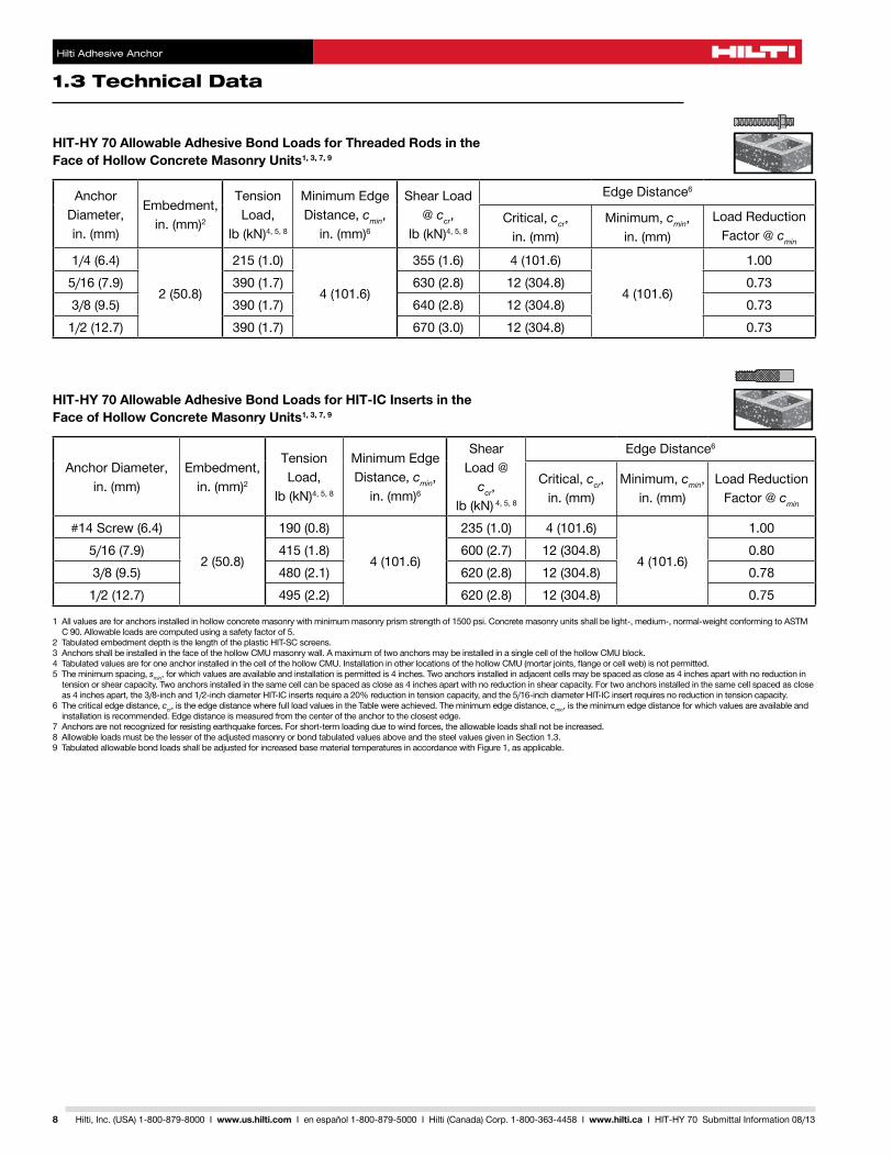
HIT-HY 70 Allowable Adhesive Bond Loads for Threaded Rods in the Face of Hollow Concrete Masonry Units1, 3, 7, 9
Anchor Diameter, in.(mm)
Embedment, in.(mm)2
Tension Load,
lb(kN)4,5,8
MinimumEdgeDistance, cmin,
in.(mm)6
Shear Load @ ccr,
lb(kN)4,5,8
EdgeDistance6
Critical, ccr, in.(mm)
Minimum, cmin, in.(mm)
LoadReductionFactor@cmin
1/4(6.4)
2(50.8)
215(1.0)
4(101.6)
355(1.6) 4(101.6)
4(101.6)
1.005/16(7.9) 390(1.7) 630(2.8) 12(304.8) 0.733/8(9.5) 390(1.7) 640(2.8) 12(304.8) 0.731/2(12.7) 390(1.7) 670(3.0) 12(304.8) 0.73
HIT-HY 70 Allowable Adhesive Bond Loads for HIT-IC Inserts in the Face of Hollow Concrete Masonry Units1, 3, 7, 9
Anchor Diameter, in.(mm)
Embedment, in.(mm)2
Tension Load,
lb(kN)4,5,8
MinimumEdgeDistance, cmin,
in.(mm)6
Shear Load @
ccr, lb(kN) 4,5,8
EdgeDistance6
Critical, ccr, in.(mm)
Minimum, cmin, in.(mm)
LoadReductionFactor@cmin
#14Screw(6.4)
2(50.8)
190(0.8)
4(101.6)
235(1.0) 4(101.6)
4(101.6)
1.005/16(7.9) 415(1.8) 600(2.7) 12(304.8) 0.803/8(9.5) 480(2.1) 620(2.8) 12(304.8) 0.781/2(12.7) 495(2.2) 620(2.8) 12(304.8) 0.75
1Allvaluesareforanchorsinstalledinhollowconcretemasonrywithminimummasonryprismstrengthof1500psi.Concretemasonryunitsshallbelight-,medium-,normal-weightconformingtoASTMC90.Allowableloadsarecomputedusingasafetyfactorof5.
2 Tabulated embedment depth is the length of the plastic HIT-SC screens.3AnchorsshallbeinstalledinthefaceofthehollowCMUmasonrywall.AmaximumoftwoanchorsmaybeinstalledinasinglecellofthehollowCMUblock.4TabulatedvaluesareforoneanchorinstalledinthecellofthehollowCMU.InstallationinotherlocationsofthehollowCMU(mortarjoints,flangeorcellweb)isnotpermitted.5Theminimumspacing,smin,forwhichvaluesareavailableandinstallationispermittedis4inches.Twoanchorsinstalledinadjacentcellsmaybespacedascloseas4inchesapartwithnoreductionintensionorshearcapacity.Twoanchorsinstalledinthesamecellcanbespacedascloseas4inchesapartwithnoreductioninshearcapacity.Fortwoanchorsinstalledinthesamecellspacedascloseas4inchesapart,the3/8-inchand1/2-inchdiameterHIT-ICinsertsrequirea20%reductionintensioncapacity,andthe5/16-inchdiameterHIT-ICinsertrequiresnoreductionintensioncapacity.
6Thecriticaledgedistance,ccr, is the edge distance where full load values in the Table were achieved. The minimum edge distance, cmin, is the minimum edge distance for which values are available and installationisrecommended.Edgedistanceismeasuredfromthecenteroftheanchortotheclosestedge.
7Anchorsarenotrecognizedforresistingearthquakeforces.Forshort-termloadingduetowindforces,theallowableloadsshallnotbeincreased.8AllowableloadsmustbethelesseroftheadjustedmasonryorbondtabulatedvaluesaboveandthesteelvaluesgiveninSection1.3.9TabulatedallowablebondloadsshallbeadjustedforincreasedbasematerialtemperaturesinaccordancewithFigure1,asapplicable.
1.3 Technical Data
Hilti Adhesive Anchor
9Hilti, Inc. (USA) 1-800-879-8000 I www.us.hilti.com I en español 1-800-879-5000 I Hilti (Canada) Corp. 1-800-363-4458 I www.hilti.ca I HIT-HY 70 Submittal Information 08/13
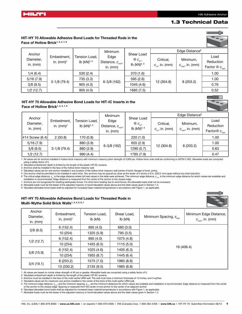
HIT-HY 70 Allowable Adhesive Bond Loads for Threaded Rods in the Face of Hollow Brick1, 3, 4, 7, 9
Anchor Diameter, in.(mm)
Embedment, in.(mm)2
Tension Load, lb(kN)5,8
Minimum Edge
Distance, cmin, in.(mm)
Shear Load @ ccr,
lb(kN)5,8
EdgeDistance6
Critical, ccr,in.(mm)
Minimum, cmin,in.(mm)
Load Reduction
Factor@cmin
1/4(6.4)
3-1/8(79.4)
530(2.4)
6-3/8(162)
370(1.6)
12(304.8) 8(203.2)
1.005/16(7.9) 735(3.3) 595(2.6) 1.003/8(9.5) 905(4.0) 1045(4.6) 0.761/2(12.7) 905(4.0) 1685(7.5) 0.52
HIT-HY 70 Allowable Adhesive Bond Loads for HIT-IC Inserts in the Face of Hollow Brick1, 3, 4, 7, 9
Anchor Diameter, in.(mm)
Embedment, in.(mm)2
Tension Load, lb(kN)5,8
Minimum Edge
Distance, cmin, in.(mm)
Shear Load @ ccr,
lb(kN)5,8
EdgeDistance6
Critical, ccr,in.(mm)
Minimum, cmin,in.(mm)
Load ReductionFactor@cmin
#14Screw(6.4) 2(50.8) 170(0.8)
6-3/8(162)
220(1.0)
12(304.8) 8(203.2)
1.005/16(7.9)
3-1/8(79.4)880(3.9) 655(2.9) 1.00
3/8(9.5) 880(3.9) 1290(5.7) 0.631/2(12.7) 990(4.4) 1785(7.9) 0.47
HIT-HY 70 Allowable Adhesive Bond Loads for Threaded Rods in Multi-Wythe Solid Brick Walls1, 3, 4, 5, 6, 7
Anchor Diameter, in.(mm)
Embedment, in.(mm)2
Tension Load, lb(kN)
Shear Load, lb(kN)
Minimum Spacing, smin
MinimumEdgeDistance,cmin,in.(mm)
3/8(9.5)6(152.4) 895(4.0) 680(3.0)
16(406.4)
10(254) 1325(5.9) 795(3.5)
1/2(12.7)6(152.4) 895(4.0) 1075(4.8)10(254) 1455(6.5) 1115(5.0)
5/8(15.9)6(152.4) 1025(4.6) 1405(6.3)10(254) 1955(8.7) 1445(6.4)
3/4(19.1)8(203.2) 1575(7.0) 1985(8.8)13(330.2) 2135(9.5) 1985(8.8)
1Allvaluesareforanchorsinstalledinhollowbrickmasonrywithminimummasonryprismstrengthof3,000psi.HollowbrickunitsshallbeconformingtoASTMC652.Allowableloadsarecomputedusingasafetyfactorof5.
2 Tabulated embedment depth is limited by the length of the plastic HIT-SC screens.3Anchorsshallbeinstalledinthefaceofthehollowbrickmasonrywall.4Tabulatedvaluesareforoneanchorinstalledinanylocationofthehollowbrickmasonrywall(centerofbrick,flangesofbrick,joints).5Oneanchorshallbepermittedtobeinstalledineachbrick.Twoanchorsmaybespacedascloseasthelesserof2bricksor8in.(203.2mm)apartwithoutanyloadreduction.6Thecriticaledgedistance,ccr, is the edge distance where full load values in the table were achieved. The minimum edge distance, cmin, is the minimum edge distance for which values are available and installationisrecommended.Edgedistanceismeasuredfromthecenteroftheanchortotheclosestedge.
7Anchorsarenotrecognizedforresistingearthquakeforces.Forshort-termloadingduetowindforces,theallowableloadsshallnotbeincreased.8AllowableloadsmustbethelesseroftheadjustedmasonryorbondtabulatedvaluesaboveandthesteelvaluesgiveninSection1.3.9TabulatedallowablebondloadsshallbeadjustedforincreasedbasematerialtemperaturesinaccordancewithFigure1,asapplicable.
1Allvaluesarebasedonmortarshearstrengthof45psiorgreater.Allowableloadsarecomputedusingasafetyfactorof5.2 Tabulated embedment depth is limited by the length of the plastic HIT-SC screens.3Anchorsmustbeinstalledinthefaceofthemulti-wytheURMwall.Thewallmusthaveaminimumthicknessof13inches,and3wythes.4Tabulatedvaluesareformaximumoneanchorinstalledinthecenterofthebrickofthemulti-wytheURMwall.5Theminimumedgedistance,cmin, and the minimum spacing, smin,aretheminimumdistancesforwhichvaluesareavailableandinstallationisrecommended.Edgedistanceismeasuredfromthecenter
of the anchor to the closest edge. Spacing is measured from the center of one anchor to the center of an adjacent anchor6TabulatedallowablebondloadsshallbeadjustedforincreasedbasematerialtemperaturesinaccordancewithFigure1,asapplicable.7AllowableloadsmustbethelesseroftheadjustedmasonryorbondtabulatedvaluesaboveandthesteelvaluesgiveninSection1.3

Hilti Adhesive Anchor
1.3 Technical Data
10 Hilti, Inc. (USA) 1-800-879-8000 I www.us.hilti.com I en español 1-800-879-5000 I Hilti (Canada) Corp. 1-800-363-4458 I www.hilti.ca I HIT-HY 70 Submittal Information 08/13
HIT-HY 70 Allowable Adhesive Bond Seismic Loads for Threaded Rods and Reinforcing Bars in Unreinforced Brick Masonry1, 2, 3
Configuration A — Shear Anchor or Rebar Dowel (Figure 4)AnchorDiameter,in.(mm)
orBarSizeEmbedment, in.(mm)
Minimum Wall Thickness,in.(mm)
Tension Load, lb(kN)
Shear Load 4, lb(kN)
1/2(12.7) No.48(203.2) 13(330.2)
- 500(2.22)5/8(15.9) No.5 - 750(3.34)3/4(19.1) No.6 - 1000(4.45)
Configuration B — 22 1/2° Combination Anchor (Figure 5)
AnchorDiameter,in.(mm)Embedment, in.(mm)
Minimum WallThickness,in.(mm)
Tension Load, lb(kN)
Shear Load 4, lb(kN)
3/4(19.1)Within1inch
of the opposite wall surface
13(330.2) 1200(5.34) 1000(4.45)
1Allowableloadvaluesareapplicableonlytoanchorswherein-placesheartestsindicateminimummortarstrengthof50psi,net.2AllowableloadsarecomputedinaccordancewithICC-ESAC60(2010)andIBC3Noincreaseforshort-termloadingispermitted,suchasloadinginducedbywindorearthquake.4AnchorsmustbetestedinaccordancewiththerequirementsofIEBCandUCBC.
Figure 4 — Hilti HIT-HY 70 Shear Anchor or Dowel (Configuration A)
Figure 5 — Hilti HIT-HY 70 Adhesive 22 1/2° Combination Anchor (Configuration B)
1.3 Technical Data
Hilti Adhesive Anchor
11Hilti, Inc. (USA) 1-800-879-8000 I www.us.hilti.com I en español 1-800-879-5000 I Hilti (Canada) Corp. 1-800-363-4458 I www.hilti.ca I HIT-HY 70 Submittal Information 08/13
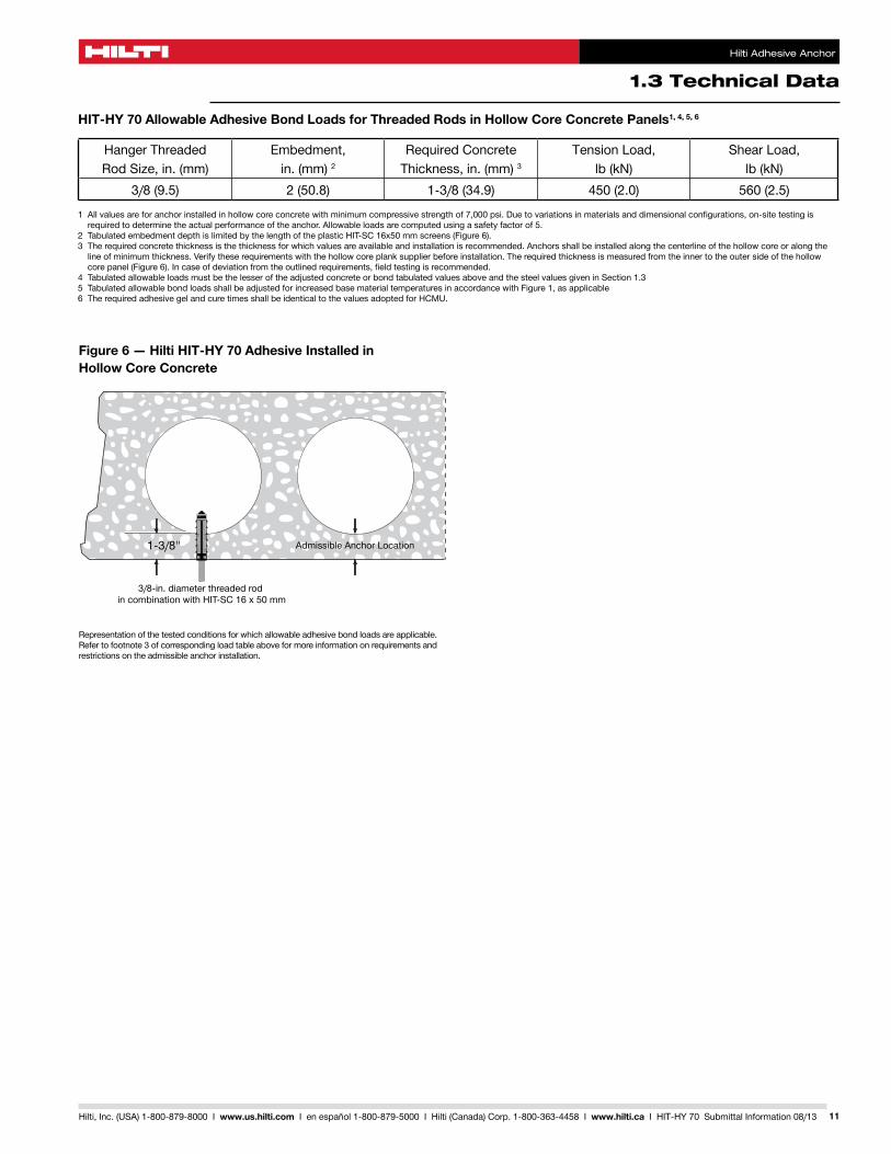
HIT-HY 70 Allowable Adhesive Bond Loads for Threaded Rods in Hollow Core Concrete Panels1, 4, 5, 6
Hanger ThreadedRodSize,in.(mm)
Embedment,in.(mm)2
RequiredConcreteThickness,in.(mm)3
Tension Load, lb(kN)
Shear Load, lb(kN)
3/8(9.5) 2(50.8) 1-3/8(34.9) 450(2.0) 560(2.5)
1Allvaluesareforanchorinstalledinhollowcoreconcretewithminimumcompressivestrengthof7,000psi.Duetovariationsinmaterialsanddimensionalconfigurations,on-sitetestingisrequiredtodeterminetheactualperformanceoftheanchor.Allowableloadsarecomputedusingasafetyfactorof5.
2TabulatedembedmentdepthislimitedbythelengthoftheplasticHIT-SC16x50mmscreens(Figure6).3Therequiredconcretethicknessisthethicknessforwhichvaluesareavailableandinstallationisrecommended.Anchorsshallbeinstalledalongthecenterlineofthehollowcoreoralongthelineofminimumthickness.Verifytheserequirementswiththehollowcoreplanksupplierbeforeinstallation.Therequiredthicknessismeasuredfromtheinnertotheoutersideofthehollowcorepanel(Figure6).Incaseofdeviationfromtheoutlinedrequirements,fieldtestingisrecommended.
4TabulatedallowableloadsmustbethelesseroftheadjustedconcreteorbondtabulatedvaluesaboveandthesteelvaluesgiveninSection1.35TabulatedallowablebondloadsshallbeadjustedforincreasedbasematerialtemperaturesinaccordancewithFigure1,asapplicable6TherequiredadhesivegelandcuretimesshallbeidenticaltothevaluesadoptedforHCMU.
Figure 6 — Hilti HIT-HY 70 Adhesive Installed in Hollow Core Concrete
1-3/8" Admissible Anchor Location
3/8-in. diameter threaded rod in combination with HIT-SC 16 x 50 mm
Representationofthetestedconditionsforwhichallowableadhesivebondloadsareapplicable.Refertofootnote3ofcorrespondingloadtableaboveformoreinformationonrequirementsandrestrictions on the admissible anchor installation.
Hilti Adhesive Anchor
1.3 Technical Data
12 Hilti, Inc. (USA) 1-800-879-8000 I www.us.hilti.com I en español 1-800-879-5000 I Hilti (Canada) Corp. 1-800-363-4458 I www.hilti.ca I HIT-HY 70 Submittal Information 08/13
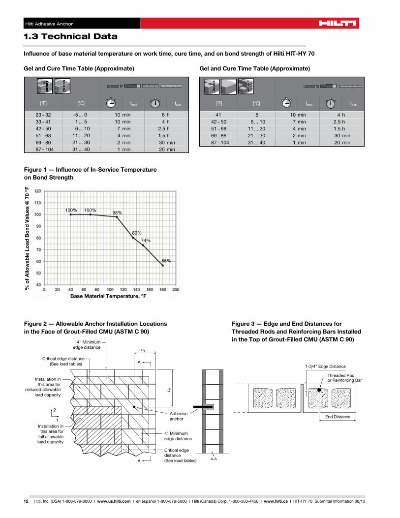
Influence of base material temperature on work time, cure time, and on bond strength of Hilti HIT-HY 70
Gel and Cure Time Table (Approximate)
6 h 4 h 2.5 h 1.5 h 30 min 20 min
4 h 2.5 h 1.5 h 30 min 20 min
10 min 7 min 4 min 2 min 1 min
5 6 ... 10 11 ... 20 21 ... 30 31 ... 40
41 42 – 50 51 – 68 69 – 86 87 – 104
10 min 10 min 7 min 4 min 2 min 1 min
23 – 32 33 – 41 42 – 50 51 – 68 69 – 86 87 – 104
-5 ... 0 1 ... 5 6 ... 10 11 ... 20 21 ... 30 31 ... 40
Figure 3 — Edge and End Distances for Threaded Rods and Reinforcing Bars Installed in the Top of Grout-Filled CMU (ASTM C 90)
Figure 1 — Influence of In-Service Temperature on Bond Strength
Base Material Temperature, °F
% o
f Allo
wab
le L
oad
Bon
d Va
lues
@ 7
0 °F
100% 100% 98%
80%74%
56%
Figure 2 — Allowable Anchor Installation Locations in the Face of Grout-Filled CMU (ASTM C 90)
4" Minimumedge distance
Critical edge distance(See load tables)
Adhesiveanchor
4" Minimumedge distance
Critical edgedistance(See load tables)A
A
c1
c 2
2
1
A-A
Installation inthis area for
full allowableload capacity
Installation inthis area for
reduced allowableload capacity
End Distance
1-3/4" Edge Distance
Threaded Rodor Reinforcing Bar
1.4 Installation Parameters
Hilti Adhesive Anchor
13Hilti, Inc. (USA) 1-800-879-8000 I www.us.hilti.com I en español 1-800-879-5000 I Hilti (Canada) Corp. 1-800-363-4458 I www.hilti.ca I HIT-HY 70 Submittal Information 08/13
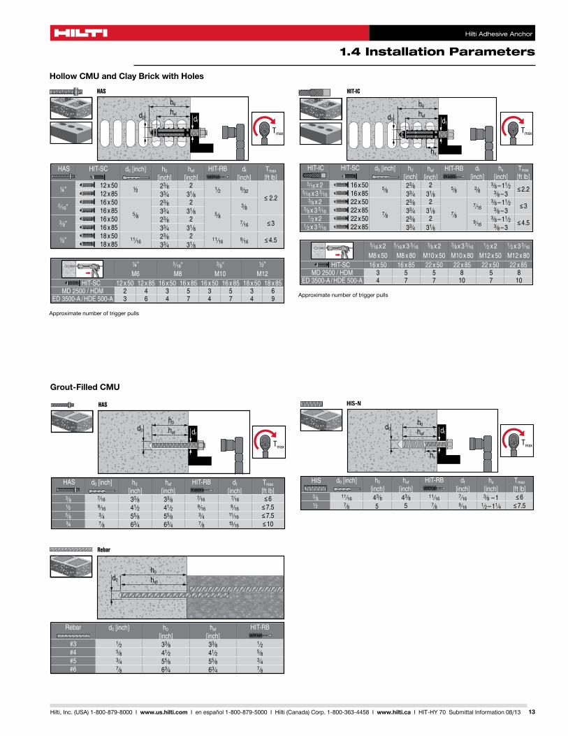
Hollow CMU and Clay Brick with Holes
Approximatenumberoftriggerpulls
Approximatenumberoftriggerpulls
Grout-Filled CMU
Hilti Adhesive Anchor
1.4 Installation Parameters
14 Hilti, Inc. (USA) 1-800-879-8000 I www.us.hilti.com I en español 1-800-879-5000 I Hilti (Canada) Corp. 1-800-363-4458 I www.hilti.ca I HIT-HY 70 Submittal Information 08/13
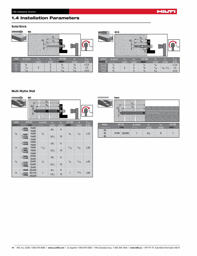
Solid Brick
Hilti HIT-HY 70
16
Rebar
Rebar HIT-SC d0 [inch] h0
[inch]hef
[inch]HIT-RB
#4#5#6
26x200 1 81⁄4 8 1
Rebar HIT-SC d0 [mm] h0
[mm]hef
[mm]HIT-RB
Ø 12Ø 16Ø 20
26x200 26 210 20 28
Multi-Wythe Wall
15Hilti, Inc. (USA) 1-800-879-8000 I www.us.hilti.com I en español 1-800-879-5000 I Hilti (Canada) Corp. 1-800-363-4458 I www.hilti.ca I HIT-HY 70 Submittal Information 08/13
Notes
Hilti. Outperform. Outlast.P.O. Box 21148, Tulsa, OK 74121 • Hilti, Inc. (U.S.) 1-800-879-8000 • www.us.hilti.com • en español 1-800-879-5000 • Hilti (Canada) Corp. 1-800-363-4458 www.hilti.ca • Hilti is an equal opportunity employer • Hilti is a registered trademark of Hilti, Corp. ©Copyright 2013 by Hilti, Inc. (U.S.) • H462 • 3488940 • 06/13 • DBS
The data contained in this literature was current as of the date of publication. Updates and changes may be made based on later testing. If verification is needed that the data is still current, please contact the Hilti Technical Support Specialists at 1-800-363-4458. All published load values contained in this literature represent the results of testing by Hilti or test organizations. Local base materials were used. Because of variations in materials, on-site testing is necessary to determine performance at any specific site. Laser beams represented by red lines in this publication. Printed in the United States
*14001 US only