Embed Size (px)
Citation preview

MS5100 Eclipse Series
User’s Guide

Disclaimer Honeywell International Inc. (“HII”) reserves the right to make changes in specifications and other information contained in this document without prior notice, and the reader should in all cases consult HII to determine whether any such changes have been made. The information in this publication does not represent a commitment on the part of HII.
HII shall not be liable for technical or editorial errors or omissions contained herein: nor for incidental or consequential damages resulting from the furnishing, performance, or use of this manual. HII disclaims all responsibility for the selection and use of software and/or hardware to achieve intended results.
This document contains proprietary information that is protected by copyright. All rights reserved. No part of this document may be photocopied, reproduced, or translated into another language without the prior written consent of HII.
© 2002 - 2016 Honeywell International Inc. All rights reserved.
Web Address: www.honeywellaidc.com
Trademarks MetroSelect, MetroSet, CodeGate, and CodeSense are a trademarks or registered trademarks of Metrologic Instruments, Inc. in the United States and/or other countries.
Microsoft, Windows, and Windows 95 are trademarks or registered trademarks of Microsoft Corporation.
IBM is a trademark of International Business Machines Corporation.
Other product names mentioned in this manual may be trademarks or registered trademarks of their respective companies and are the property of their respective owners.
Patents For patent information, refer to www.hsmpats.com.
iii
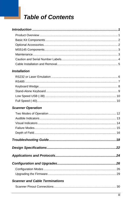
Table of Contents
Introduction ............................................................................................. 1 Product Overview ............................................................................................. 1 Basic Kit Components ...................................................................................... 2 Optional Accessories ........................................................................................ 2 MS5145 Components ....................................................................................... 3 Maintenance ..................................................................................................... 3 Caution and Serial Number Labels ................................................................... 4 Cable Installation and Removal ........................................................................ 5
Installation RS232 or Laser Emulation ............................................................................... 6 RS485 .............................................................................................................. 7 Keyboard Wedge .............................................................................................. 8 Stand-Alone Keyboard ..................................................................................... 9 Low Speed USB (-38) .................................................................................... 10 Full Speed (-40) .............................................................................................. 10
Scanner Operation Two Modes of Operation ................................................................................ 12 Audible Indicators ........................................................................................... 13 Visual Indicators ............................................................................................. 14 Failure Modes ................................................................................................. 15 Depth of Field ................................................................................................. 16
Troubleshooting Guide ......................................................................... 18
Design Specifications ........................................................................... 22
Applications and Protocols .................................................................. 24
Configuration and Upgrades ................................................................ 26 Configuration Modes ...................................................................................... 26 Upgrading the Firmware ................................................................................. 29
Scanner and Cable Terminations Scanner Pinout Connections .......................................................................... 30

iv
Cable Connector Configurations .................................................................... 32
Index ....................................................................................................... 34
Customer Support ................................................................................. 35
1
Introduction
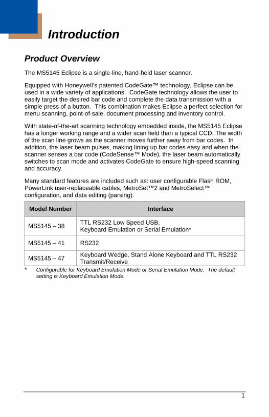
Product Overview The MS5145 Eclipse is a single-line, hand-held laser scanner.
Equipped with Honeywell’s patented CodeGate™ technology, Eclipse can be used in a wide variety of applications. CodeGate technology allows the user to easily target the desired bar code and complete the data transmission with a simple press of a button. This combination makes Eclipse a perfect selection for menu scanning, point-of-sale, document processing and inventory control.
With state-of-the-art scanning technology embedded inside, the MS5145 Eclipse has a longer working range and a wider scan field than a typical CCD. The width of the scan line grows as the scanner moves further away from bar codes. In addition, the laser beam pulses, making lining up bar codes easy and when the scanner senses a bar code (CodeSense™ Mode), the laser beam automatically switches to scan mode and activates CodeGate to ensure high-speed scanning and accuracy.
Many standard features are included such as: user configurable Flash ROM, PowerLink user-replaceable cables, MetroSet™2 and MetroSelect™ configuration, and data editing (parsing).
Model Number Interface
MS5145 – 38 TTL RS232 Low Speed USB, Keyboard Emulation or Serial Emulation*
MS5145 – 41 RS232
MS5145 – 47 Keyboard Wedge, Stand Alone Keyboard and TTL RS232 Transmit/Receive
* Configurable for Keyboard Emulation Mode or Serial Emulation Mode. The default setting is Keyboard Emulation Mode.
2
Basic Kit Components Part # Description
MS5145 Eclipse Scanner
00-02544 MetroSelect Single-Line Configuration Guide*
70-79016 MS5100 Eclipse Series User’s Guide*
* Manuals are available for download from www.honeywellaidc.com.
Optional Accessories
Part # Description
55-55000x-3 RS232 PowerLink Cable with Built-in Power Jack straight cord, long strain relief, black
55-55002x-3 Keyboard Wedge PowerLink Cable with Adapter straight cord, long strain relief, black
55-55020x-3 Stand Alone Keyboard PowerLink Cable, straight cord, long strain relief, black
55-55235x-N-3 USB Low Speed Communication Cable, Type A straight cord, long strain relief, black
55-55200x-N-3
USB Full Speed Cable, Locking Plus-Power™ Type A straight cord, long strain relief, black Note: This cable is for use with full speed USB (-40)
interface only.
MVC** RS485 Applications, MVC Cable, ±12VDC to +5.2VDC
** Contact a customer service representative for additional information on the MVC cable series and the host connections available.
46-46633 Countertop Stand
Other items may be ordered for the specific protocol being used. To order additional items, contact the dealer, distributor, or customer service. See page 35 for contact information.
3
MS5145 Components
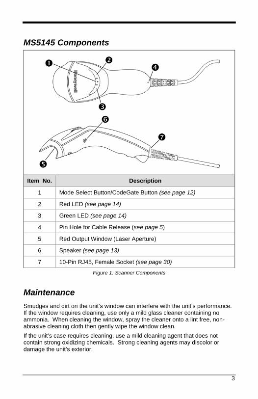
Item No. Description
1 Mode Select Button/CodeGate Button (see page 12)
2 Red LED (see page 14)
3 Green LED (see page 14)
4 Pin Hole for Cable Release (see page 5)
5 Red Output Window (Laser Aperture)
6 Speaker (see page 13)
7 10-Pin RJ45, Female Socket (see page 30)
Figure 1. Scanner Components
Maintenance Smudges and dirt on the unit’s window can interfere with the unit’s performance. If the window requires cleaning, use only a mild glass cleaner containing no ammonia. When cleaning the window, spray the cleaner onto a lint free, non-abrasive cleaning cloth then gently wipe the window clean. If the unit’s case requires cleaning, use a mild cleaning agent that does not contain strong oxidizing chemicals. Strong cleaning agents may discolor or damage the unit’s exterior.
4
Caution and Serial Number Labels
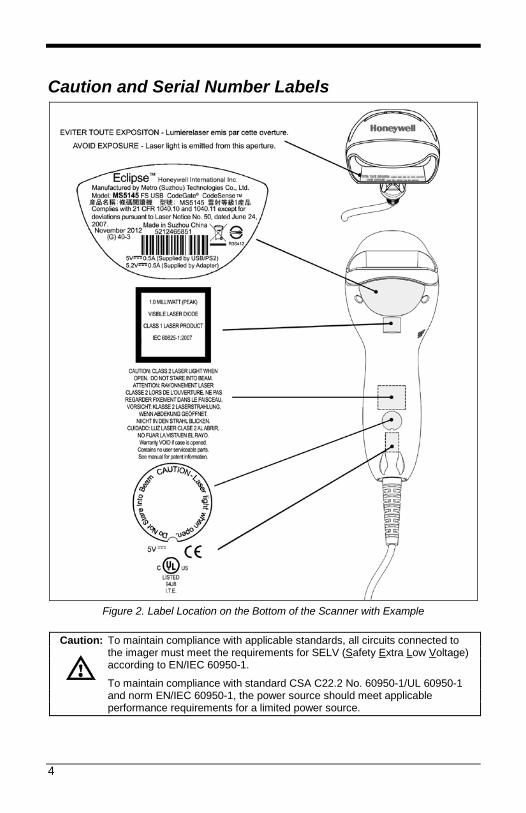
Figure 2. Label Location on the Bottom of the Scanner with Example
Caution: To maintain compliance with applicable standards, all circuits connected to
the imager must meet the requirements for SELV (Safety Extra Low Voltage) according to EN/IEC 60950-1.
To maintain compliance with standard CSA C22.2 No. 60950-1/UL 60950-1 and norm EN/IEC 60950-1, the power source should meet applicable performance requirements for a limited power source.
5
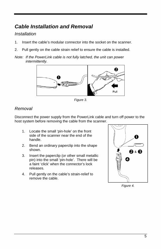
Cable Installation and Removal Installation
1. Insert the cable’s modular connector into the socket on the scanner.
2. Pull gently on the cable strain relief to ensure the cable is installed.
Note: If the PowerLink cable is not fully latched, the unit can power intermittently.
Figure 3.
Removal
Disconnect the power supply from the PowerLink cable and turn off power to the host system before removing the cable from the scanner.
1. Locate the small ‘pin-hole’ on the front side of the scanner near the end of the handle.
2. Bend an ordinary paperclip into the shape shown.
3. Insert the paperclip (or other small metallic pin) into the small ‘pin-hole’. There will be a faint ‘click’ when the connector’s lock releases.
4. Pull gently on the cable’s strain-relief to remove the cable.
Figure 4.

6
Installation
RS232 or Laser Emulation 1. Turn off the host system. 2. Plug the male, 10-pin RJ45 end of the
PowerLink cable into the 10-pin socket on the MS5145.
3. Connect the 9-pin female end of the PowerLink cable to the appropriate communication port on the host device.
4. Plug the external power supply into the power jack on the PowerLink cable.
5. Check the AC input requirements of the power supply to make sure eth voltage matches the AC outlet. The outlet must be located near the equipment.
6. Connect AC power to the transformer. 7. Turn on the host system.
Installation Notes Plugging the scanner into the serial port of the PC does not guarantee
that scanned information will appear at the PC. A software driver and correct configuration settings are also required for proper communications to occur.
Powering the MS5145 directly from the host device can sometimes cause interference with the operation of the scanner or the computer. Not all computers supply the same current. For this reason, using an external power supply is recommended. For additional information, contact a customer service representative.
All MS5145-00 scanners leave the factory with the Laser Emulation Mode enabled. If recall defaults is scanned while re-configuring the scanner the Laser Emulation Mode will no longer be enabled. Refer to the MS5145-00 Laser Emulation Mode section of the MetroSelect Single-Line Configuration Guide for information on enabling the Laser Emulation Mode.
See caution on page 4.
Figure 5. RS232 or Laser Emulation
7
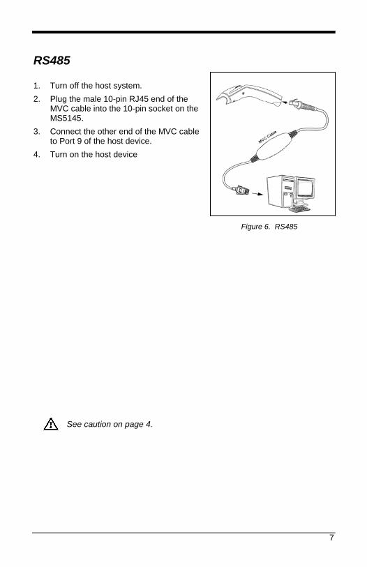
RS485 1. Turn off the host system. 2. Plug the male 10-pin RJ45 end of the
MVC cable into the 10-pin socket on the MS5145.
3. Connect the other end of the MVC cable to Port 9 of the host device.
4. Turn on the host device
See caution on page 4.
Figure 6. RS485

8
Keyboard Wedge 1. Turn off the host system. 2. Plug the male, 10-pin RJ45 end of the
PowerLink cable into the 10-pin socket on the MS5145.
3. Disconnect the keyboard from the host/PC.
4. Connect the Y ends of the PowerLink cable to the keyboard and the host’s keyboard port. If necessary, use the supplied adapter cable to make the connections.
5. Plug the external power supply into the power jack on the PowerLink cable.
6. Check the AC input requirements of the power supply to make sure the voltage matches the AC outlet. The outlet must be located near the equipment
7. Connect AC power to the transformer. 8. Turn on the host system.
Installation Note Powering the MS5145-47 directly from the computer can sometimes cause interference with the operation of the scanner or the computer. Not all computers supply the same current through the keyboard port, explaining why a scanner may work on one computer and not another. Contact a customer service representative if an external power supply is required.
See caution on page 4.
Figure 7. Keyboard Wedge
9
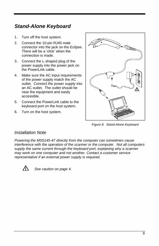
Stand-Alone Keyboard 1. Turn off the host system. 2. Connect the 10-pin RJ45 male
connector into the jack on the Eclipse. There will be a ‘click’ when the connection is made.
3. Connect the L-shaped plug of the power supply into the power jack on the PowerLink cable.
4. Make sure the AC input requirements of the power supply match the AC outlet. Connect the power supply into an AC outlet. The outlet should be near the equipment and easily accessible.
5. Connect the PowerLink cable to the keyboard port on the host system.
6. Turn on the host system.
Installation Note
Powering the MS5145-47 directly from the computer can sometimes cause interference with the operation of the scanner or the computer. Not all computers supply the same current through the keyboard port, explaining why a scanner may work on one computer and not another. Contact a customer service representative if an external power supply is required.
See caution on page 4.
Figure 8. Stand-Alone Keyboard

10
Figure 9. USB
USB: Low Speed USB (-38) Full Speed USB (-40)
1. Turn off the host system. 2. Connect the 10-pin RJ45 male
connector of the USB cable into the jack on the Eclipse. There will be a ‘click’ when the connection is made.
3. Connect the other end of the USB cable to the host USB port.
4. Turn on the host system.
Installation Notes As a default, the MS5145-38 leaves the factory with USB Keyboard
Emulation Mode enabled. For information on configuring the MS5145-38 for USB Serial Emulation
Mode, please refer to the USB section of the MetroSelect Single-Line Configuration Guide..
Plugging the scanner into a port on the host system does not guarantee that scanned information will be communicated properly to the host system. All Eclipse’s are shipped already configured with a set of factory defaults. Please refer to the MetroSelect Single-Line Configuration Guide or MetroSet2’s help files for instructions on changing the scanner’s factory default configuration. The scanner and host system must use the same communication protocols.
See caution on page 4.

11
12
Scanner Operation
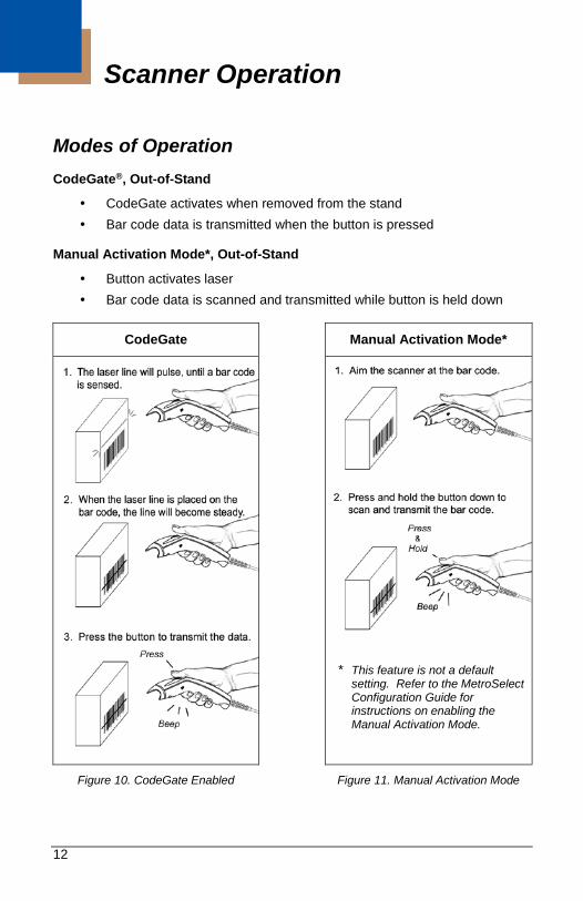
Modes of Operation CodeGate®, Out-of-Stand
CodeGate activates when removed from the stand Bar code data is transmitted when the button is pressed
Manual Activation Mode*, Out-of-Stand
Button activates laser Bar code data is scanned and transmitted while button is held down
CodeGate Manual Activation Mode*
* This feature is not a default setting. Refer to the MetroSelect Configuration Guide for instructions on enabling the Manual Activation Mode.
Figure 10. CodeGate Enabled Figure 11. Manual Activation Mode
13
Audible Indicators When the MS5145 scanner is operational, the scanner provides audible feedback to indicate the status of the scanner and the last scan. Eight settings are available for the tone of the beep (normal, six alternate tones and no tone). For instructions on how to change the tone of the beeper, refer to the Single-Line MetroSelect Configuration Guide.
One Beep – On Power Up The green LED will turn on, then the red LED will flash and the scanner will beep once. The red LED will remain on for the duration of the beep. The scanner is now ready to scan.
One Beep – During Operation When the scanner successfully reads a bar code, the red LED will flash and the scanner will beep once (if programmed to do so). If the scanner does not beep once and the red light does not flash, then the bar code has not been successfully read.
Three Beeps – During Operation When entering the configuration mode, the red LED will flash while the scanner simultaneously beeps three times. The red LED will continue to flash until the unit exits configuration mode. Upon exiting configuration mode, the scanner will beep three times and the red LED will stop flashing.
When configured for communication timeout, three beeps during operation will indicate that a communication timeout has occurred.
Three Beeps – On Power Up This is a failure indicator. Refer to the Failure Modes section of this guide on page 15.
Razzberry Tone This is a failure indicator or an invalid code read during configuration mode. Refer to the Failure Modes section of this guide on page 15.
14
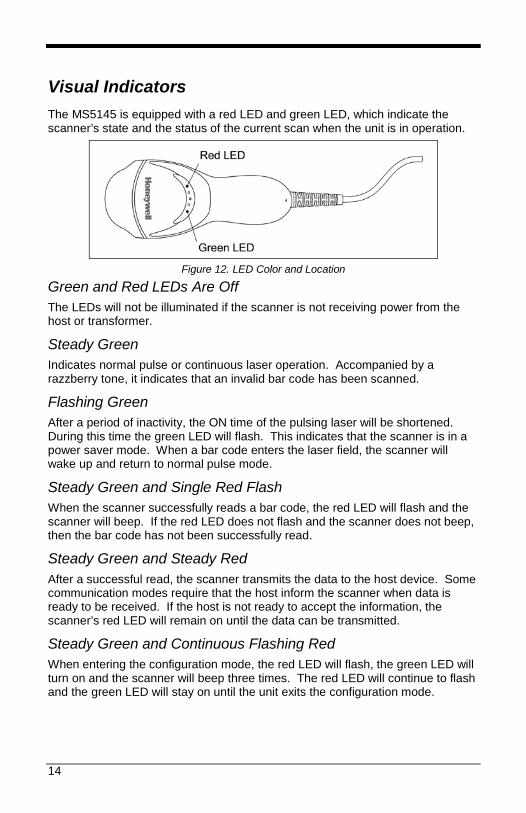
Visual Indicators The MS5145 is equipped with a red LED and green LED, which indicate the scanner’s state and the status of the current scan when the unit is in operation.
Figure 12. LED Color and Location
Green and Red LEDs Are Off The LEDs will not be illuminated if the scanner is not receiving power from the host or transformer.
Steady Green Indicates normal pulse or continuous laser operation. Accompanied by a razzberry tone, it indicates that an invalid bar code has been scanned.
Flashing Green After a period of inactivity, the ON time of the pulsing laser will be shortened. During this time the green LED will flash. This indicates that the scanner is in a power saver mode. When a bar code enters the laser field, the scanner will wake up and return to normal pulse mode.
Steady Green and Single Red Flash When the scanner successfully reads a bar code, the red LED will flash and the scanner will beep. If the red LED does not flash and the scanner does not beep, then the bar code has not been successfully read.
Steady Green and Steady Red After a successful read, the scanner transmits the data to the host device. Some communication modes require that the host inform the scanner when data is ready to be received. If the host is not ready to accept the information, the scanner’s red LED will remain on until the data can be transmitted.
Steady Green and Continuous Flashing Red When entering the configuration mode, the red LED will flash, the green LED will turn on and the scanner will beep three times. The red LED will continue to flash and the green LED will stay on until the unit exits the configuration mode.

15
Failure Modes One Razzberry Tone – On Power Up This indicates the scanner has experienced a laser or flipper subsystem failure. Return the unit for repair to an Authorized Service Center.
Continuous Razzberry Tone with no LEDs If, upon power up, the scanner emits a continuous razzberry tone, then the scanner has an experienced an electronic failure. Return the unit for repair to an Authorized Service Center.
Three Beeps – On Power Up If the scanner beeps three times on power up, then the non-volatile memory (NovRAM) that holds the scanner configuration has failed. Return the unit for repair to an Authorized Service Center.
16
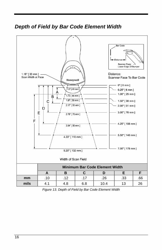
Depth of Field by Bar Code Element Width
Minimum Bar Code Element Width
A B C D E F mm .10 .12 .17 .26 .33 .66 mils 4.1 4.8 6.8 10.4 13 26
Figure 13. Depth of Field by Bar Code Element Width

17
18
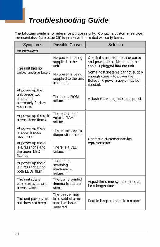
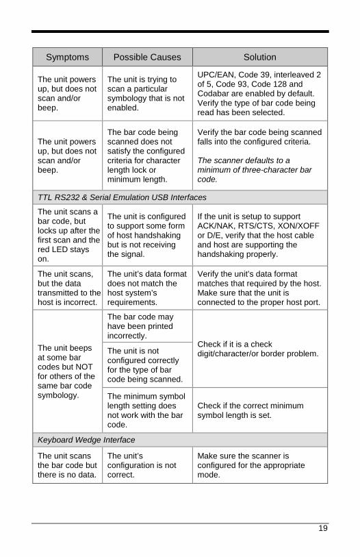
Troubleshooting Guide The following guide is for reference purposes only. Contact a customer service representative (see page 35) to preserve the limited warranty terms.
Symptoms Possible Causes Solution All Interfaces
The unit has no LEDs, beep or laser.
No power is being supplied to the unit.
Check the transformer, the outlet and power strip. Make sure the cable is plugged into the unit.
No power is being supplied to the unit from host.
Some host systems cannot supply enough current to power the Eclipse. A power supply may be needed.
At power up the unit beeps two times and alternately flashes the LEDs.
There is a ROM failure. A flash ROM upgrade is required.
At power up the unit beeps three times.
There is a non-volatile RAM failure.
Contact a customer service representative.
At power up there is a continuous razz tone.
There has been a diagnostic failure.
At power up there is a razz tone and the green LED flashes.
There is a VLD failure.
At power up there is a razz tone and both LEDs flash.
There is a scanning mechanism failure.
The unit scans, communicates and beeps twice.
The same symbol timeout is set too short.
Adjust the same symbol timeout for a longer time.
The unit powers up, but does not beep.
The beeper may be disabled or no tone has been selected.
Enable beeper and select a tone.
19
Symptoms Possible Causes Solution
The unit powers up, but does not scan and/or beep.
The unit is trying to scan a particular symbology that is not enabled.
UPC/EAN, Code 39, interleaved 2 of 5, Code 93, Code 128 and Codabar are enabled by default. Verify the type of bar code being read has been selected.
The unit powers up, but does not scan and/or beep.
The bar code being scanned does not satisfy the configured criteria for character length lock or minimum length.
Verify the bar code being scanned falls into the configured criteria. The scanner defaults to a minimum of three-character bar code.
TTL RS232 & Serial Emulation USB Interfaces
The unit scans a bar code, but locks up after the first scan and the red LED stays on.
The unit is configured to support some form of host handshaking but is not receiving the signal.
If the unit is setup to support ACK/NAK, RTS/CTS, XON/XOFF or D/E, verify that the host cable and host are supporting the handshaking properly.
The unit scans, but the data transmitted to the host is incorrect.
The unit’s data format does not match the host system’s requirements.
Verify the unit’s data format matches that required by the host. Make sure that the unit is connected to the proper host port.
The unit beeps at some bar codes but NOT for others of the same bar code symbology.
The bar code may have been printed incorrectly.
Check if it is a check digit/character/or border problem. The unit is not
configured correctly for the type of bar code being scanned.
The minimum symbol length setting does not work with the bar code.
Check if the correct minimum symbol length is set.
Keyboard Wedge Interface
The unit scans the bar code but there is no data.
The unit’s configuration is not correct.
Make sure the scanner is configured for the appropriate mode.
20
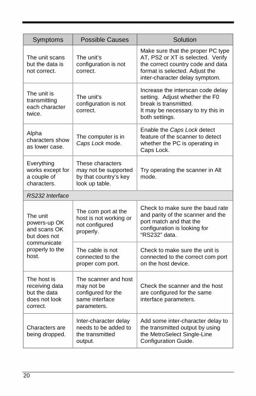
Symptoms Possible Causes Solution
The unit scans but the data is not correct.
The unit’s configuration is not correct.
Make sure that the proper PC type AT, PS2 or XT is selected. Verify the correct country code and data format is selected. Adjust the inter-character delay symptom.
The unit is transmitting each character twice.
The unit’s configuration is not correct.
Increase the interscan code delay setting. Adjust whether the F0 break is transmitted. It may be necessary to try this in both settings.
Alpha characters show as lower case.
The computer is in Caps Lock mode.
Enable the Caps Lock detect feature of the scanner to detect whether the PC is operating in Caps Lock.
Everything works except for a couple of characters.
These characters may not be supported by that country’s key look up table.
Try operating the scanner in Alt mode.
RS232 Interface
The unit powers-up OK and scans OK but does not communicate properly to the host.
The com port at the host is not working or not configured properly.
Check to make sure the baud rate and parity of the scanner and the port match and that the configuration is looking for “RS232” data.
The cable is not connected to the proper com port.
Check to make sure the unit is connected to the correct com port on the host device.
The host is receiving data but the data does not look correct.
The scanner and host may not be configured for the same interface parameters.
Check the scanner and the host are configured for the same interface parameters.
Characters are being dropped.
Inter-character delay needs to be added to the transmitted output.
Add some inter-character delay to the transmitted output by using the MetroSelect Single-Line Configuration Guide.

21
22
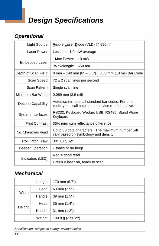
Design Specifications
Operational Light Source: Visible Laser Diode (VLD) @ 650 nm
Laser Power: Less than 1.0 mW average
Embedded Laser: Max Power: 10 mW
Wavelength: 650 nm
Depth of Scan Field: 0 mm – 140 mm (0" – 5.5") 0.33 mm (13 mil) Bar Code
Scan Speed: 72 ± 2 scan lines per second
Scan Pattern: Single scan line
Minimum Bar Width: 0.089 mm (3.5 mil)
Decode Capability: Autodiscriminates all standard bar codes. For other code types, call a customer service representative.
System Interfaces: RS232, Keyboard Wedge, USB, RS485, Stand Alone Keyboard
Print Contrast: 35% minimum reflectance difference
No. Characters Read: Up to 80 data characters. The maximum number will vary based on symbology and density.
Roll, Pitch, Yaw: 38°, 67°, 52°
Beeper Operation: 7 tones or no beep
Indicators (LED): Red = good read
Green = laser on, ready to scan
Mechanical Length: 170 mm (6.7")
Width Head: 63 mm (2.5")
Handle: 39 mm (1.5")
Height Head: 35 mm (1.4")
Handle: 31 mm (1.2")
Weight: 100.8 g (3.56 oz) Specifications subject to change without notice.
23
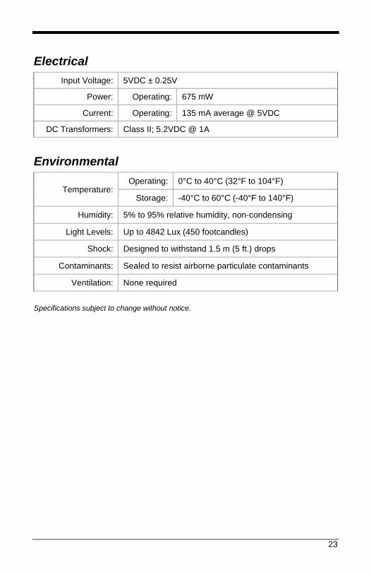
Electrical Input Voltage: 5VDC ± 0.25V
Power: Operating: 675 mW
Current: Operating: 135 mA average @ 5VDC
DC Transformers: Class II; 5.2VDC @ 1A
Environmental
Temperature: Operating: 0°C to 40°C (32°F to 104°F)
Storage: -40°C to 60°C (-40°F to 140°F)
Humidity: 5% to 95% relative humidity, non-condensing
Light Levels: Up to 4842 Lux (450 footcandles)
Shock: Designed to withstand 1.5 m (5 ft.) drops
Contaminants: Sealed to resist airborne particulate contaminants
Ventilation: None required Specifications subject to change without notice.
24
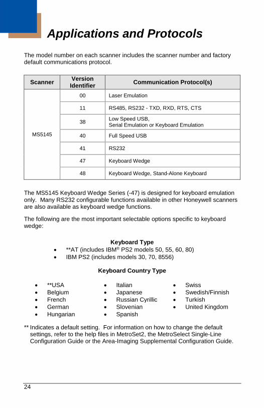
Applications and Protocols The model number on each scanner includes the scanner number and factory default communications protocol.
Scanner Version Identifier Communication Protocol(s)
MS5145
00 Laser Emulation
11 RS485, RS232 - TXD, RXD, RTS, CTS
38 Low Speed USB, Serial Emulation or Keyboard Emulation
40 Full Speed USB
41 RS232
47 Keyboard Wedge
48 Keyboard Wedge, Stand-Alone Keyboard
The MS5145 Keyboard Wedge Series (-47) is designed for keyboard emulation only. Many RS232 configurable functions available in other Honeywell scanners are also available as keyboard wedge functions.
The following are the most important selectable options specific to keyboard wedge:
Keyboard Type • **AT (includes IBM® PS2 models 50, 55, 60, 80) • IBM PS2 (includes models 30, 70, 8556)
Keyboard Country Type
• **USA • Italian • Swiss • Belgium • Japanese • Swedish/Finnish • French • Russian Cyrillic • Turkish • German • Slovenian • United Kingdom • Hungarian • Spanish
** Indicates a default setting. For information on how to change the default
settings, refer to the help files in MetroSet2, the MetroSelect Single-Line Configuration Guide or the Area-Imaging Supplemental Configuration Guide.

25

26
Configuration and Upgrades
Configuration Modes The MS5145 Eclipse has three modes of configuration. • Bar Codes
The Eclipse can be configured by scanning the bar codes located in the MetroSelect® Single-Line Configuration Guide. This manual is available for download at www.honeywellaidc.com.
• MetroSet®2
This user-friendly Windows®-based configuration program allows you to simply ‘point-and-click’ at the desired scanner options. MetroSet2 is available for download at www.honeywellaidc.com.
• Serial Programming
This mode of configuration is ideal for OEM applications. Serial programming mode gives the end-user the ability to send a series of commands using the serial port of the host system. The commands are equivalent to the numerical values of the bar codes located in the MetroSelect Single-Line Configuration Guide.
How does Serial Configuration work? 1. Each command sent to the scanner is the ASCII representation of each
numeral in the configuration bar code. The entire numeric string is framed with an ASCII [stx] and an ASCII [etx].
EXAMPLE #1: Command for Disabling Codabar Command = [stx]100104[etx] String Sent to Scanner = 02h 31h 30h 30h 31h 30h 34h 03h (All values are hexadecimal).
2. If the command sent to the scanner is valid, the scanner will respond with an
[ack]. 3. If the command sent to the scanner in invalid, the scanner will respond with
a [nak].
Note: If this occurs, the end-user must start over at the very beginning of the configuration sequence. Re-transmitting the invalid command will not work. The user must start over.
27
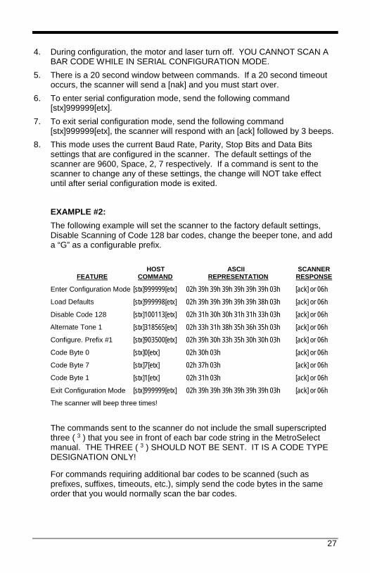
4. During configuration, the motor and laser turn off. YOU CANNOT SCAN A
BAR CODE WHILE IN SERIAL CONFIGURATION MODE. 5. There is a 20 second window between commands. If a 20 second timeout
occurs, the scanner will send a [nak] and you must start over. 6. To enter serial configuration mode, send the following command
[stx]999999[etx]. 7. To exit serial configuration mode, send the following command
[stx]999999[etx], the scanner will respond with an [ack] followed by 3 beeps. 8. This mode uses the current Baud Rate, Parity, Stop Bits and Data Bits
settings that are configured in the scanner. The default settings of the scanner are 9600, Space, 2, 7 respectively. If a command is sent to the scanner to change any of these settings, the change will NOT take effect until after serial configuration mode is exited.
EXAMPLE #2: The following example will set the scanner to the factory default settings, Disable Scanning of Code 128 bar codes, change the beeper tone, and add a “G” as a configurable prefix.
FEATURE HOST
COMMAND ASCII
REPRESENTATION SCANNER
RESPONSE
Enter Configuration Mode [stx]999999[etx] 02h 39h 39h 39h 39h 39h 39h 03h [ack] or 06h Load Defaults [stx]999998[etx] 02h 39h 39h 39h 39h 39h 38h 03h [ack] or 06h Disable Code 128 [stx]100113[etx] 02h 31h 30h 30h 31h 31h 33h 03h [ack] or 06h Alternate Tone 1 [stx]318565[etx] 02h 33h 31h 38h 35h 36h 35h 03h [ack] or 06h Configure. Prefix #1 [stx]903500[etx] 02h 39h 30h 33h 35h 30h 30h 03h [ack] or 06h Code Byte 0 [stx]0[etx] 02h 30h 03h [ack] or 06h Code Byte 7 [stx]7[etx] 02h 37h 03h [ack] or 06h Code Byte 1 [stx]1[etx] 02h 31h 03h [ack] or 06h Exit Configuration Mode [stx]999999[etx] 02h 39h 39h 39h 39h 39h 39h 03h [ack] or 06h The scanner will beep three times!
The commands sent to the scanner do not include the small superscripted three ( 3 ) that you see in front of each bar code string in the MetroSelect manual. THE THREE ( 3 ) SHOULD NOT BE SENT. IT IS A CODE TYPE DESIGNATION ONLY!
For commands requiring additional bar codes to be scanned (such as prefixes, suffixes, timeouts, etc.), simply send the code bytes in the same order that you would normally scan the bar codes.
28
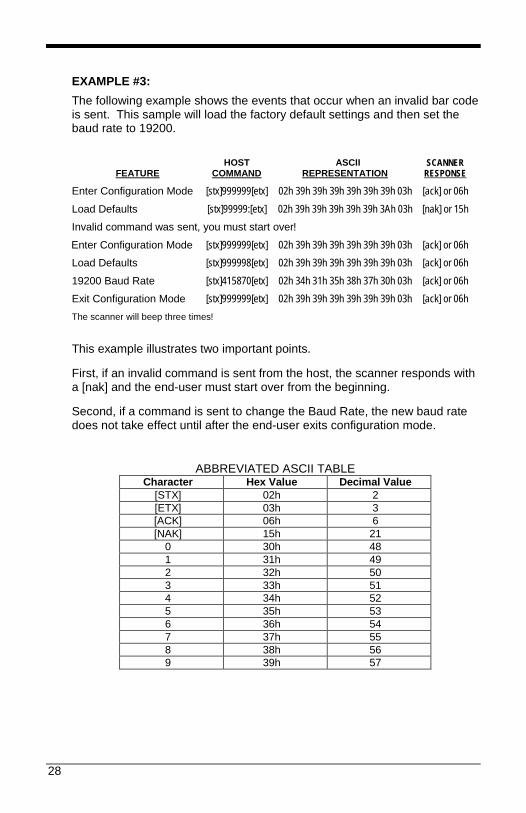
EXAMPLE #3: The following example shows the events that occur when an invalid bar code is sent. This sample will load the factory default settings and then set the baud rate to 19200.
FEATURE HOST
COMMAND ASCII
REPRESENTATION SCANNER
RESPONSE
Enter Configuration Mode [stx]999999[etx] 02h 39h 39h 39h 39h 39h 39h 03h [ack] or 06h Load Defaults [stx]99999:[etx] 02h 39h 39h 39h 39h 39h 3Ah 03h [nak] or 15h Invalid command was sent, you must start over! Enter Configuration Mode [stx]999999[etx] 02h 39h 39h 39h 39h 39h 39h 03h [ack] or 06h Load Defaults [stx]999998[etx] 02h 39h 39h 39h 39h 39h 39h 03h [ack] or 06h 19200 Baud Rate [stx]415870[etx] 02h 34h 31h 35h 38h 37h 30h 03h [ack] or 06h Exit Configuration Mode [stx]999999[etx] 02h 39h 39h 39h 39h 39h 39h 03h [ack] or 06h The scanner will beep three times!
This example illustrates two important points.
First, if an invalid command is sent from the host, the scanner responds with a [nak] and the end-user must start over from the beginning.
Second, if a command is sent to change the Baud Rate, the new baud rate does not take effect until after the end-user exits configuration mode.
ABBREVIATED ASCII TABLE
Character Hex Value Decimal Value [STX] 02h 2 [ETX] 03h 3 [ACK] 06h 6 [NAK] 15h 21
0 30h 48 1 31h 49 2 32h 50 3 33h 51 4 34h 52 5 35h 53 6 36h 54 7 37h 55 8 38h 56 9 39h 57
29
Upgrading the Firmware The MS5145 is part of Honeywell’s line of scanners with flash upgradeable firmware. The upgrade process requires a new firmware file supplied to the customer by a customer service representative and Honeywell’s MetroSet2 software. A personal computer running Windows 95 or greater with an available RS232 serial or USB port is required to complete the upgrade.
Note: PowerLink cable #54-54014 is required when using RS232 for the upgrade process. To order this cable contact a customer service representative. Do not use the standard cable supplied with keyboard wedge or RS485 scanner interface kits. If using USB for the upgrade process, the standard USB cable provided with the scanner can be used.
To upgrade the firmware in the MS5145:
1. Plug the scanner into a serial communication port on the host system. 2. Start the MetroSet2 software. 3. Click on the plus sign (+) next to POS Scanners to expand the supported
scanner list. 4. Choose the MS5145 Eclipse from the list. 5. Click on the Configure Eclipse/5145 Scanner button. 6. Choose Flash Utility from the options list located on the left side of the
screen. 7. Click on the Open File button in the Flash Utility window. 8. Locate and open the flash upgrade file. 9. Select the COM port that the scanner is connected to on the host system. 10. Verify the settings listed in the Flash Utility window. 11. Click on the Flash Scanner button to begin the flash upgrade. 12. A message will appear on the screen when the upgrade is complete.
See Contact Information on page 35.
MetroSet2 is available for download, at no additional cost, from www.honeywellaidc.com.
30
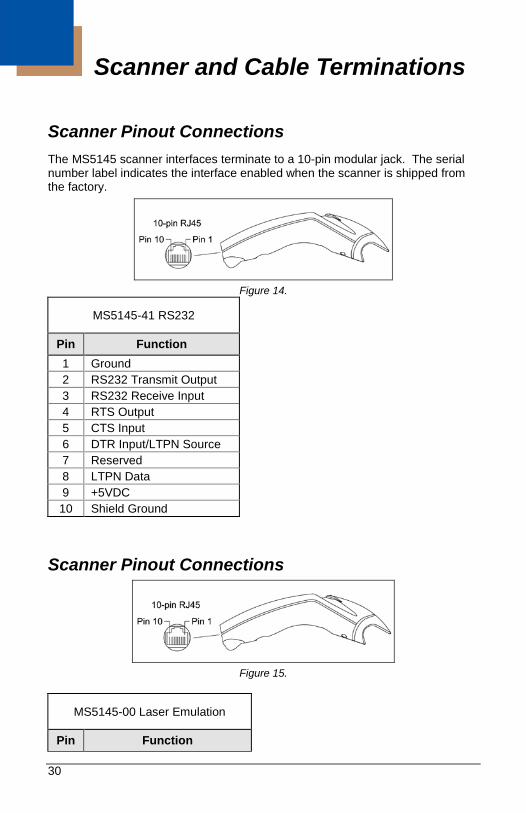
Scanner and Cable Terminations
Scanner Pinout Connections The MS5145 scanner interfaces terminate to a 10-pin modular jack. The serial number label indicates the interface enabled when the scanner is shipped from the factory.
Figure 14.
MS5145-41 RS232
Pin Function 1 Ground 2 RS232 Transmit Output 3 RS232 Receive Input 4 RTS Output 5 CTS Input 6 DTR Input/LTPN Source 7 Reserved 8 LTPN Data 9 +5VDC 10 Shield Ground
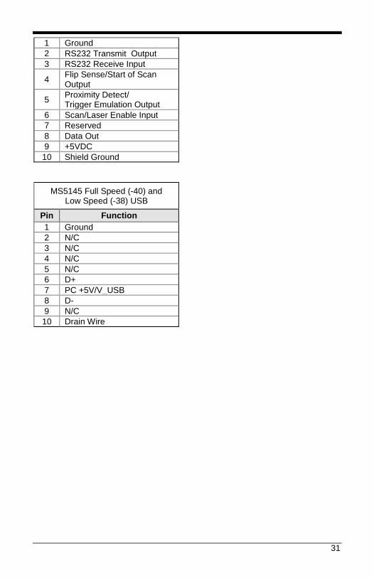
Scanner Pinout Connections
Figure 15.
MS5145-00 Laser Emulation
Pin Function
31
1 Ground 2 RS232 Transmit Output 3 RS232 Receive Input
4 Flip Sense/Start of Scan Output
5 Proximity Detect/ Trigger Emulation Output
6 Scan/Laser Enable Input 7 Reserved 8 Data Out 9 +5VDC 10 Shield Ground
MS5145 Full Speed (-40) and Low Speed (-38) USB
Pin Function 1 Ground 2 N/C 3 N/C 4 N/C 5 N/C 6 D+ 7 PC +5V/V_USB 8 D- 9 N/C 10 Drain Wire
32
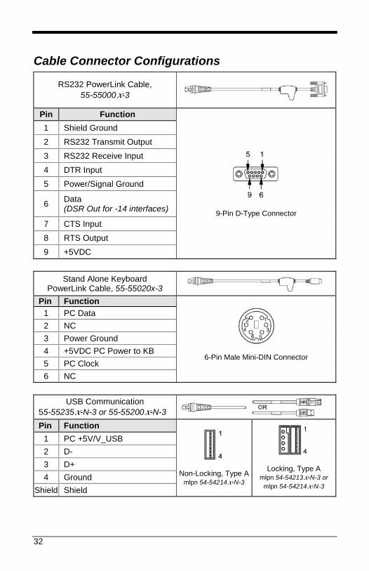
Cable Connector Configurations
RS232 PowerLink Cable, 55-55000x-3
Pin Function
9-Pin D-Type Connector
1 Shield Ground
2 RS232 Transmit Output
3 RS232 Receive Input
4 DTR Input
5 Power/Signal Ground
6 Data (DSR Out for -14 interfaces)
7 CTS Input
8 RTS Output
9 +5VDC
Stand Alone Keyboard PowerLink Cable, 55-55020x-3
Pin Function
6-Pin Male Mini-DIN Connector
1 PC Data 2 NC 3 Power Ground 4 +5VDC PC Power to KB 5 PC Clock 6 NC
USB Communication
55-55235x-N-3 or 55-55200x-N-3 Pin Function
Non-Locking, Type A mlpn 54-54214x-N-3
Locking, Type A mlpn 54-54213x-N-3 or
mlpn 54-54214x-N-3
1 PC +5V/V_USB 2 D- 3 D+ 4 Ground
Shield Shield
33
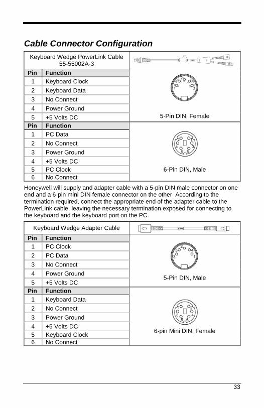
Cable Connector Configuration Keyboard Wedge PowerLink Cable
55-55002A-3 Pin Function
5-Pin DIN, Female
1 Keyboard Clock 2 Keyboard Data 3 No Connect 4 Power Ground 5 +5 Volts DC
Pin Function
6-Pin DIN, Male
1 PC Data 2 No Connect 3 Power Ground 4 +5 Volts DC 5 PC Clock 6 No Connect
Honeywell will supply and adapter cable with a 5-pin DIN male connector on one end and a 6-pin mini DIN female connector on the other According to the termination required, connect the appropriate end of the adapter cable to the PowerLink cable, leaving the necessary termination exposed for connecting to the keyboard and the keyboard port on the PC.
Keyboard Wedge Adapter Cable Pin Function
5-Pin DIN, Male
1 PC Clock 2 PC Data 3 No Connect 4 Power Ground 5 +5 Volts DC
Pin Function
6-pin Mini DIN, Female
1 Keyboard Data 2 No Connect 3 Power Ground 4 +5 Volts DC 5 Keyboard Clock 6 No Connect
34
Index A AC .................................. see power accessories ................................... 2 aperture ......................................... 3
B beeper .........................see indicator button ................................ 3, 12, 26
C cable .................... 18–19, 33, 30–33
communication . 2, 5, 6–11, 20 MVC ...................................... 2 PowerLink 5, 6–11, 33, 30–33 USB .....................................10
CodeGate ................................ 3, 12 compliance .................................... 4 CONFIGURATION ........... 24, 33, 30–33 customer service ........................... 2
D DC .................................. see power default.......................... 6, 24, 27, 28 depth of field ................................ 16
F flash ............................................... 1
G green ...........................see indicator
I indicator ....................................... 22
audible................ 3, 13, 18–19 failure ..................... 15, 18–19 visual .................. 3, 14, 18–19
interface....................................... 22 Keyboard Wedge .. 1, 2, 8, 24,
30, 33 Laser Emulation ..............6, 30 RS232 ........ 1, 2, 6, 24, 30, 32 RS485 .................. 1, 7, 24, 30 Stand-Alone Keyboard .1, 2, 9,
24, 30, 32
TTL RS232 ..................... 1, 30 USB ................. 1, 2, 24, 30, 32
K Keyboard Wedge ........ see interface
L label .............................................. 4 laser .................................... 3, 4, 22 LED ............................. see indicator
M manual .......................................... 2 modes ................................... 12, 26
P power .................................. 2, 6, 22 PowerLink ........................ see cable
R red ............................... see indicator RS232 ......................... see interface RS485 ......................... see interface
S Service ........................................ 36 stand ............................................. 2 Stand-Alone Keyboard see interface
T TERMINATIONS ......................... 30–33 tone ......................................... 1, 13 transformer ...................... see power troubleshooting ..................... 18–19 TTL RS232.................. see interface
U USB ............................ see interface
V VLD ............................................. 22
W window .......................................... 3

35
Customer Support Technical Assistance To search our knowledge base for a solution or to log in to the Technical Support portal and report a problem, go to www.hsmcontactsupport.com. For our latest contact information, see www.honeywellaidc.com/locations. Product Service and Repair Honeywell International Inc. provides service for all of its products through service centers throughout the world. To find your service center, go to www.honeywellaidc.com and select Get Resources > Service and Repair. Contact your service enter to obtain a Return Material Authorization number (RMA #) before you return the product. To obtain warranty or non-warranty service, return your product to Honeywell (postage paid) with a copy of the dated purchase record. Limited Warranty For warranty information, go to www.honeywellaidc.com and click Get Resources > Product Warranty. Send Feedback Your feedback is crucial to the continual improvement of our documentation. To provide feedback about this manual, contact the Honeywell Technical Communications department at [email protected].

Honeywell Scanning & Mobility 9680 Old Bailes Road Fort Mill, SC 29707 www.honeywellaidc.com
70-79016 Rev J 9/16