Embed Size (px)
DESCRIPTION
Midland programig
Citation preview

70-147070-147070-147070-1470
TITAN MOBILE PROGRAMMING SOFTWARETITAN MOBILE PROGRAMMING SOFTWARETITAN MOBILE PROGRAMMING SOFTWARETITAN MOBILE PROGRAMMING SOFTWARE
USER’S MANUALUSER’S MANUALUSER’S MANUALUSER’S MANUAL
70-99822510/01
2001, Midland Radio Corporation2
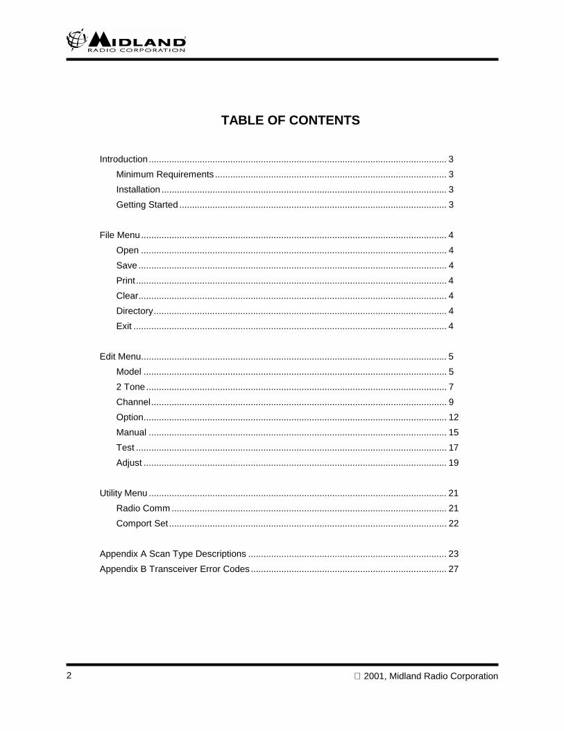
TABLE OF CONTENTS
Introduction..................................................................................................................... 3Minimum Requirements ........................................................................................... 3Installation ................................................................................................................ 3Getting Started ......................................................................................................... 3
File Menu........................................................................................................................ 4Open ........................................................................................................................ 4Save ......................................................................................................................... 4Print.......................................................................................................................... 4Clear......................................................................................................................... 4Directory................................................................................................................... 4Exit ........................................................................................................................... 4
Edit Menu........................................................................................................................ 5Model ....................................................................................................................... 52 Tone...................................................................................................................... 7Channel.................................................................................................................... 9Option....................................................................................................................... 12Manual ..................................................................................................................... 15Test .......................................................................................................................... 17Adjust ....................................................................................................................... 19
Utility Menu ..................................................................................................................... 21Radio Comm ............................................................................................................ 21Comport Set ............................................................................................................. 22
Appendix A Scan Type Descriptions .............................................................................. 23Appendix B Transceiver Error Codes ............................................................................. 27
2001, Midland Radio Corporation 3
INTRODUCTIONThe 70-1470 PC Programming Software allows the user to program Midland Titan Mobile Radios. It runsunder Windows 95/98. It cannot run under DOS or Windows 3.xx.
MINIMUM REQUIREMENTS
IBM-Compatible PCWindows 951 MB Hard Drive Space
INSTALLATION
Use Windows Explorer to create a new folder (directory) on your hard drive, for example, C:\70-1470. Copythe 70-1470-3.5 disk contents to this directory.
GETTING STARTED
NOTE: The display should be set to at least 800x600 pixels for proper viewing. In general, it is a good idea toupload a radio, or open a saved file, rather than create a new file from scratch. There are many settings on theEdit Channel and Edit Option windows that affect proper radio operation.
From the start menu select Run and type C:\70-1470\Titan320.exe where C:\70-1470 is the directory the diskcontents were copied to in Installation above. The program will start at the Model screen. From the Utilitymenu select Comport Set and select the communications port 70-1309 programming cable is plugged into.
1. To upload the contents of a radio into the program select Radio Comm from the Utility menu.
2. Make sure the radio is not in scan then turn the radio off. Plug the programming cable into themicrophone jack. Turn the radio back on.
3. Click the Up Load button. A Please wait dialog box will pop up and the radio display will readCOPY (CPY). If an error occurs repeat step 2.
4. After successful upload an EEPROM copy complete dialog box will pop-up. Click the OK button.
5. To edit the programming select Model from the Edit menu. A Copy OK? dialog box will pop-up.Select OK to overwrite any configuration data that is already resident in the program (At this pointonly the default configuration data is resident. This process is necessary so the Verify function canwork properly).
6. Select Channel from the Edit menu to check and/or edit channel data. Select other screens(Option, 2 Tone, etc.) to edit other parameters as required.
7. Select Radio Comm from the Utility menu. Click the Down Load button to write the editedconfiguration data to the radio EEPROM. The radio will display PROG (PRG) while downloading.When the download is complete an EEPROM program complete dialog box will pop-up and theradio will display SCI. Click the OK button, turn the radio off and unplug the programming cable.
2001, Midland Radio Corporation4
FILE MENU
OPENSelect Open from the File menu to bring up an Open dialog box to retrieve a previously created data file. Thefile extension is .dmp.
SAVESelect Save from the File menu to bring up a Save As dialog box to save the current configuration data to afile. The file extension is .dmp.
PRINTSelect Print then Text Format from the File menu to bring up a print preview dialog box of the currentconfiguration data. Click the Print button to bring up the Print dialog box, or click the Close button to canceland return to the previous window. Select Print then Hex Dump to print a listing of the hexadecimal data thatthe program sends to the EEPROM.
CLEARSelect Clear from the File menu to reset all current configuration data to default values. All currentconfiguration data will be lost if it has not been previously saved.
DIRECTORYSelect Directory from the File menu to specify the default Open and Save As directories used by the program.
EXITSelect Exit from the File menu to close the program. All current configuration data will be lost if it has not beenpreviously saved.
2001, Midland Radio Corporation 5
EDIT MENU
MODEL
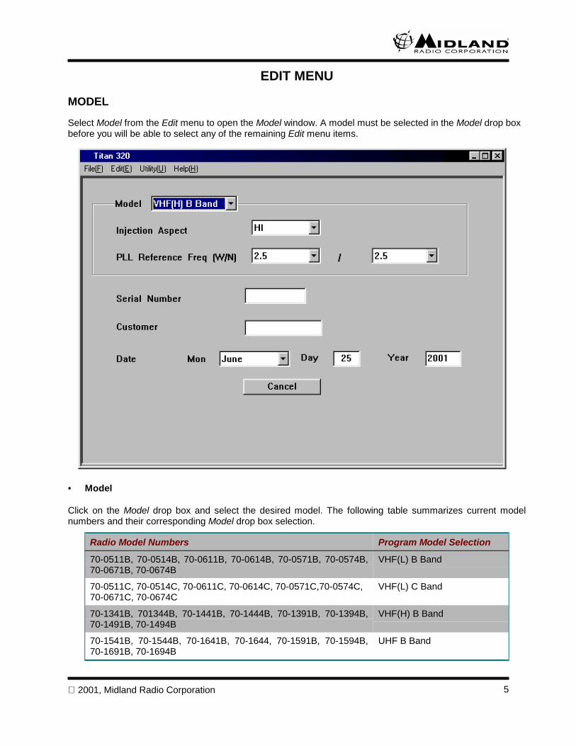
Select Model from the Edit menu to open the Model window. A model must be selected in the Model drop boxbefore you will be able to select any of the remaining Edit menu items.
• Model
Click on the Model drop box and select the desired model. The following table summarizes current modelnumbers and their corresponding Model drop box selection.
Radio Model Numbers Program Model Selection
70-0511B, 70-0514B, 70-0611B, 70-0614B, 70-0571B, 70-0574B,70-0671B, 70-0674B
VHF(L) B Band
70-0511C, 70-0514C, 70-0611C, 70-0614C, 70-0571C,70-0574C,70-0671C, 70-0674C
VHF(L) C Band
70-1341B, 701344B, 70-1441B, 70-1444B, 70-1391B, 70-1394B,70-1491B, 70-1494B
VHF(H) B Band
70-1541B, 70-1544B, 70-1641B, 70-1644, 70-1591B, 70-1594B,70-1691B, 70-1694B
UHF B Band
2001, Midland Radio Corporation6
• Injection Aspect
The Injection Aspect drop box will automatically be completed when the Model is selected. Do not change itunless an alternate injection kit has been installed in the radio.
• PLL Reference Freq
Click on the PLL Reference Freq drop boxes to select the prescaler reference frequencies for wide band (W)and narrow band (N). Available selections vary by the Model selected. All receive and transmit frequencies tobe programmed into the radio must be evenly divisible by the selected reference frequencies.
• Serial Number
(Optional) Enter a serial number to be associated with the radio in the Serial Number box. Enter up to 8alphanumeric characters.
• Customer
(Optional) Enter a customer name to be associated with the radio in the Customer box. Enter up to 10alphanumeric characters.
• Date
The current system date will automatically be entered in the Date boxes, but can be edited if desired.
2001, Midland Radio Corporation 7
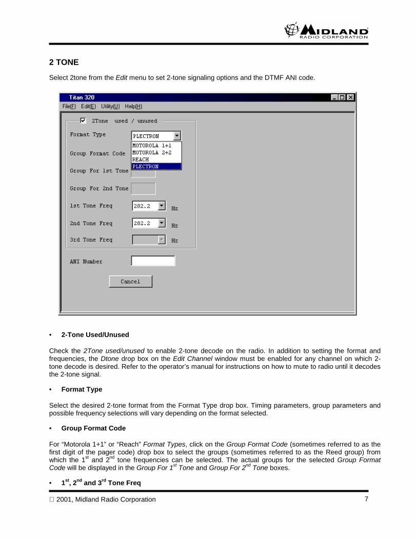
2 TONE
Select 2tone from the Edit menu to set 2-tone signaling options and the DTMF ANI code.
• 2-Tone Used/Unused
Check the 2Tone used/unused to enable 2-tone decode on the radio. In addition to setting the format andfrequencies, the Dtone drop box on the Edit Channel window must be enabled for any channel on which 2-tone decode is desired. Refer to the operator’s manual for instructions on how to mute to radio until it decodesthe 2-tone signal.
• Format Type
Select the desired 2-tone format from the Format Type drop box. Timing parameters, group parameters andpossible frequency selections will vary depending on the format selected.
• Group Format Code
For “Motorola 1+1” or “Reach” Format Types, click on the Group Format Code (sometimes referred to as thefirst digit of the pager code) drop box to select the groups (sometimes referred to as the Reed group) fromwhich the 1st and 2nd tone frequencies can be selected. The actual groups for the selected Group FormatCode will be displayed in the Group For 1st Tone and Group For 2nd Tone boxes.
• 1st, 2nd and 3rd Tone Freq
2001, Midland Radio Corporation8
Click on the 1st Tone Freq and 2nd Tone Freq drop box to select the 1st and 2nd tone frequencies. 3rd tonefrequency selection is available for ““Motorola 2+2” Format Type.
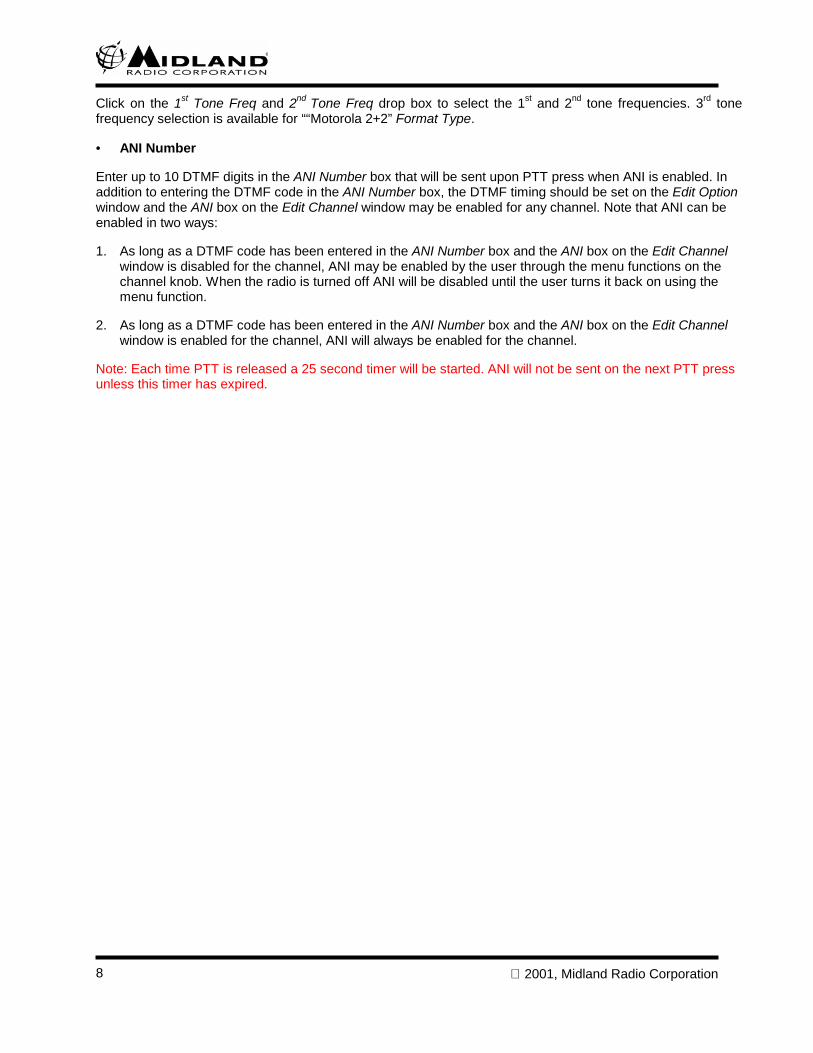
• ANI Number
Enter up to 10 DTMF digits in the ANI Number box that will be sent upon PTT press when ANI is enabled. Inaddition to entering the DTMF code in the ANI Number box, the DTMF timing should be set on the Edit Optionwindow and the ANI box on the Edit Channel window may be enabled for any channel. Note that ANI can beenabled in two ways:
1. As long as a DTMF code has been entered in the ANI Number box and the ANI box on the Edit Channelwindow is disabled for the channel, ANI may be enabled by the user through the menu functions on thechannel knob. When the radio is turned off ANI will be disabled until the user turns it back on using themenu function.
2. As long as a DTMF code has been entered in the ANI Number box and the ANI box on the Edit Channelwindow is enabled for the channel, ANI will always be enabled for the channel.
Note: Each time PTT is released a 25 second timer will be started. ANI will not be sent on the next PTT pressunless this timer has expired.
2001, Midland Radio Corporation 9
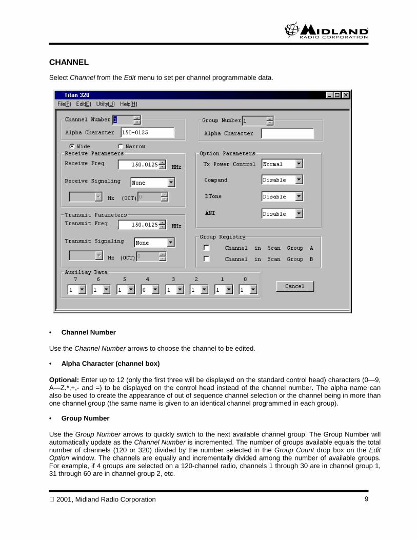
CHANNEL
Select Channel from the Edit menu to set per channel programmable data.
• Channel Number
Use the Channel Number arrows to choose the channel to be edited.
• Alpha Character (channel box)
Optional: Enter up to 12 (only the first three will be displayed on the standard control head) characters (0—9,A—Z.*,+,- and =) to be displayed on the control head instead of the channel number. The alpha name canalso be used to create the appearance of out of sequence channel selection or the channel being in more thanone channel group (the same name is given to an identical channel programmed in each group).
• Group Number
Use the Group Number arrows to quickly switch to the next available channel group. The Group Number willautomatically update as the Channel Number is incremented. The number of groups available equals the totalnumber of channels (120 or 320) divided by the number selected in the Group Count drop box on the EditOption window. The channels are equally and incrementally divided among the number of available groups.For example, if 4 groups are selected on a 120-channel radio, channels 1 through 30 are in channel group 1,31 through 60 are in channel group 2, etc.
2001, Midland Radio Corporation10
The channel groups can be used to bring the number of channels a user has available and/or is scanning atone time down to a more manageable size. The menu functions on the channel knob allow the user to selectthe current group and whether the radio scans just the current group or all groups.
• Alpha Character (group box)
Optional: Enter up to 12 (only the first three will be displayed on the standard control head) characters (0—9,A—Z.*,+,- and =) to be displayed on the control head instead of the group number when the user performsgroup selection.
• Wide/Narrow
Click the Wide or Narrow bullet to select the occupied bandwidth desired for the current channel.
• Receive Channel Freq
Click on the Receive Freq arrows, or directly enter the desired receive frequency (in MHz) in the Receive Freqbox.
• Receive Signaling
Click on the Receive Signaling drop box and select CTCSS to set a receive CTCSS decode frequency. Thenuse the left drop box to select the desired CTCSS frequency (67.0 – 254.1 Hz).
Click on the Receive Signaling drop box and select DCS to set a receive DCS decode code. Then use thearrows on the right box to select the desired DCS code (0-777).
Click on the Receive Signaling drop box and select None to clear any previously selected signaling type.
• Transmit Channel Freq
Click on the Transmit Freq arrows, or directly enter the desired transmit frequency (in MHz) in the TransmitFreq box.
• Transmit Signaling
Click on the Transmit Signaling drop box and select CTCSS to set a transmit CTCSS encode frequency. Thenuse the left drop box to select the desired CTCSS frequency (67.0 – 254.1 Hz).
Click on the Transmit Signaling drop box and select DCS to set a transmit DCS encode code. Then use thearrows on the right box to select the desired DCS code (0-777).
Click on the Transmit Signaling drop box and select None to clear any previously selected signaling type.
• TX Power Control
Click on the TX Power Control drop box then select Lowpower or Normal to set the transmit power level usedon the channel. The actual power level corresponding to each selection may be adjusted on the Edit Adjustwindow.
• Compand
Click on the Compand drop box to Enable or Disable the compander circuit.
2001, Midland Radio Corporation 11
• Dtone (2-Tone)
Click on the Dtone drop box to Enable or Disable 2-tone decode on the current channel.
• ANI
Click on the ANI drop box and select Enable or Disable for ANI operation.
1. As long as a DTMF code has been entered in the ANI Number box on the Edit 2tone window and the ANIbox on the Edit Channel window is set to Disable for the channel, ANI may be enabled by the user throughthe menu functions on the channel knob. When the radio is turned off ANI will be disabled until the userturns it back on using the menu function.
2. As long as a DTMF code has been entered in the ANI Number box on the Edit 2tone window and the ANIbox on the Edit Channel window is set to Enable for the channel, ANI will always be enabled for thechannel.
Note: Each time PTT is released a 25 second timer will be started. ANI will not be sent on the next PTT pressunless this timer has expired.
• Group Registry
Check the Channel in Scan Group A box to initially register the channel in the scan list when using Type A andType P/S scan types. The scan type depends on the Scan Type selected on the Edit Option window and thescan type selected on the channel knob menu selections by the user. The user may also set the radio to scanonly channels in the selected Channel Group (See Group Count on the Edit Option window) or allprogrammed channels registered in the Scan Group A. Channels may also be added or deleted from the scanlist by the user. The conditions under which the user additions and deletions are reset are programmableunder the Scan List Clear on the Edit Option window.
Check the Channel in Scan Group B box to initially register the channel in the scan list when using Type B orType B’ scan types. The scan type depends on the Scan Type selected on the Edit Option window and thescan type selected on the channel knob menu selections by the user. The user may also set the radio to scanonly channels in the selected Channel Group (See Group Count on the Edit Option window) or allprogrammed channels registered in the Scan Group B. Channels may also be added or deleted from the scanlist by the user. The conditions under which the user additions and deletions are reset are programmableunder Scan List Clear on the Edit Option window.
• Auxiliary Data
Click on an Auxiliary Data drop box to select either 0 or 1 for each of the 8 bits of auxiliary data (used only foroptional functions). This auxiliary data is sent in serial form for each channel when the channel is selected.When AUX STB pin (J903 pin 1) is pulsed, the previous 8 bits on the DATA pin (J401 pin 3, using DCLK toclock the data) correspond to the Auxiliary Data settings.
2001, Midland Radio Corporation12
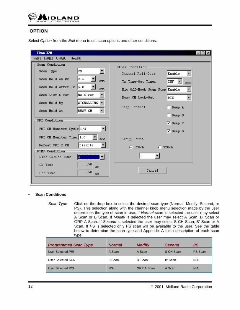
OPTION
Select Option from the Edit menu to set scan options and other conditions.
• Scan Conditions
Scan Type Click on the drop box to select the desired scan type (Normal, Modify, Second, orPS). This selection along with the channel knob menu selection made by the userdetermines the type of scan in use. If Normal scan is selected the user may selectA Scan or B Scan. If Modify is selected the user may select A Scan, B’ Scan orGRP A Scan. If Second is selected the user may select S CH Scan, B’ Scan or AScan. If PS is selected only PS scan will be available to the user. See the tablebelow to determine the scan type and Appendix A for a description of each scantype.
Programmed Scan Type Normal Modify Second PSUser Selected PRI A Scan A Scan S CH Scan PS Scan
User Selected SCN B Scan B’ Scan B’ Scan N/A
User Selected P/S N/A GRP A Scan A Scan N/A
2001, Midland Radio Corporation 13
Scan Hold on RX Click on the drop box to select the length of time, in seconds, that scan waits after asignal has been received before resuming. The time interval begins upon loss ofthe signal that stopped scan. Choose 0.5, 2.5, 5.0, or Infinite (if Infinite is selected,can will not resume until the operator rotates the Channel Knob).
Scan Hold on TX Click on the drop box to select the length of time, in seconds, that scan waits beforeresuming after PTT has been released. Choose 0.5, 2.5, 5.0, or Infinite (if Infinite isselected, scan will not resume until the operator rotates the Channel Knob).
Scan List Clear Click on the drop box to select the condition that clears the scan list (Power/Scan,When Power On, When Scan Off, No Clear). The list will be reset to the settings ofthe Channel in Scan Group A or B check boxes on the Edit Channel screen and theOne Group Scan/All Group Scan channel knob menu selection.
Scan Hold By Click on the drop box to select NSQ (scan holds when carrier is present) orSIGNALING (scan holds when a CTCSS tone or DCS code is present).
Scan Hold At Click on the drop box to choose if scan holds on a VACANT CH or BUSY CH.
• PRI Condition
PRI Ch Monitor Cycle Click on the drop box to select the priority channel sampling ratio (1/4 or 1/8). Thisdetermines the number of non-priority channels that will be scanned with eachsampling of a priority channel.
PRI Ch Monitor Time Click on the drop box to select the number of seconds (0.5, 0.75, 1.0 or 1.5)between each priority channel sampling.
Defeat PRI2 CH Click on the drop box to enable/disable use of a Priority 2 channel. If Defeat PRI2CH is chosen as Disable and a PRI2 channel has been assigned, the PRI2 channelwill be checked every third priority sampling. If Defeat PRI2 CH is selected asEnable, there will be no PRI2 channel sampling.
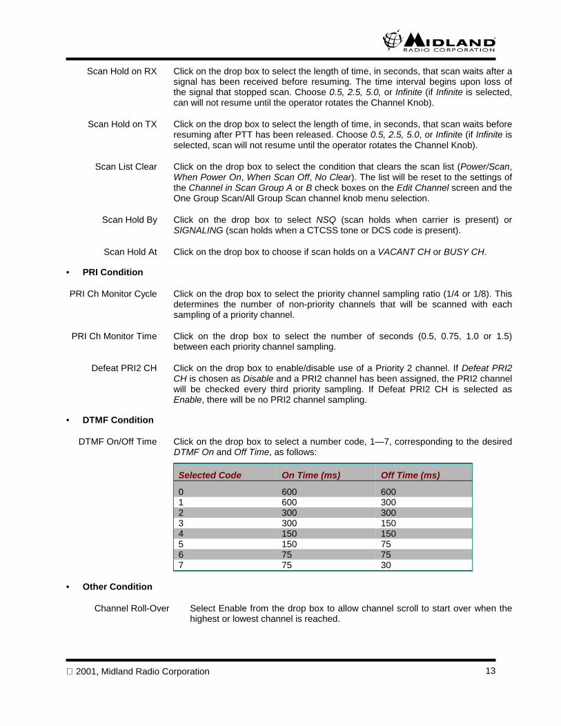
• DTMF Condition
DTMF On/Off Time Click on the drop box to select a number code, 1—7, corresponding to the desiredDTMF On and Off Time, as follows:
Selected Code On Time (ms) Off Time (ms)
0 600 6001 600 3002 300 3003 300 1504 150 1505 150 756 75 757 75 30
• Other Condition
Channel Roll-Over Select Enable from the drop box to allow channel scroll to start over when thehighest or lowest channel is reached.
2001, Midland Radio Corporation14
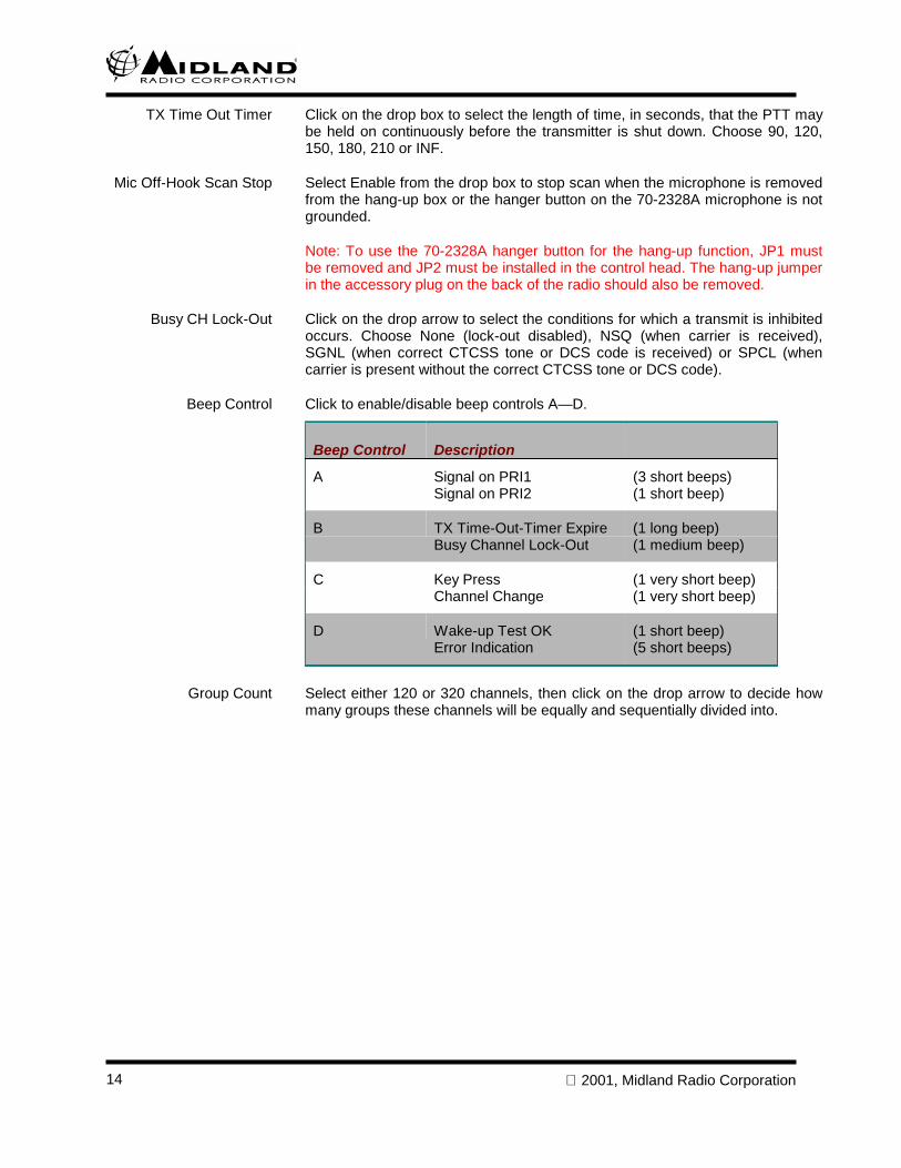
TX Time Out Timer Click on the drop box to select the length of time, in seconds, that the PTT maybe held on continuously before the transmitter is shut down. Choose 90, 120,150, 180, 210 or INF.
Mic Off-Hook Scan Stop Select Enable from the drop box to stop scan when the microphone is removedfrom the hang-up box or the hanger button on the 70-2328A microphone is notgrounded.
Note: To use the 70-2328A hanger button for the hang-up function, JP1 mustbe removed and JP2 must be installed in the control head. The hang-up jumperin the accessory plug on the back of the radio should also be removed.
Busy CH Lock-Out Click on the drop arrow to select the conditions for which a transmit is inhibitedoccurs. Choose None (lock-out disabled), NSQ (when carrier is received),SGNL (when correct CTCSS tone or DCS code is received) or SPCL (whencarrier is present without the correct CTCSS tone or DCS code).
Beep Control Click to enable/disable beep controls A—D.
Beep Control Description
A Signal on PRI1 (3 short beeps)Signal on PRI2 (1 short beep)
B TX Time-Out-Timer Expire (1 long beep)Busy Channel Lock-Out (1 medium beep)
C Key Press (1 very short beep)Channel Change (1 very short beep)
D Wake-up Test OK (1 short beep)Error Indication (5 short beeps)
Group Count Select either 120 or 320 channels, then click on the drop arrow to decide howmany groups these channels will be equally and sequentially divided into.
2001, Midland Radio Corporation 15
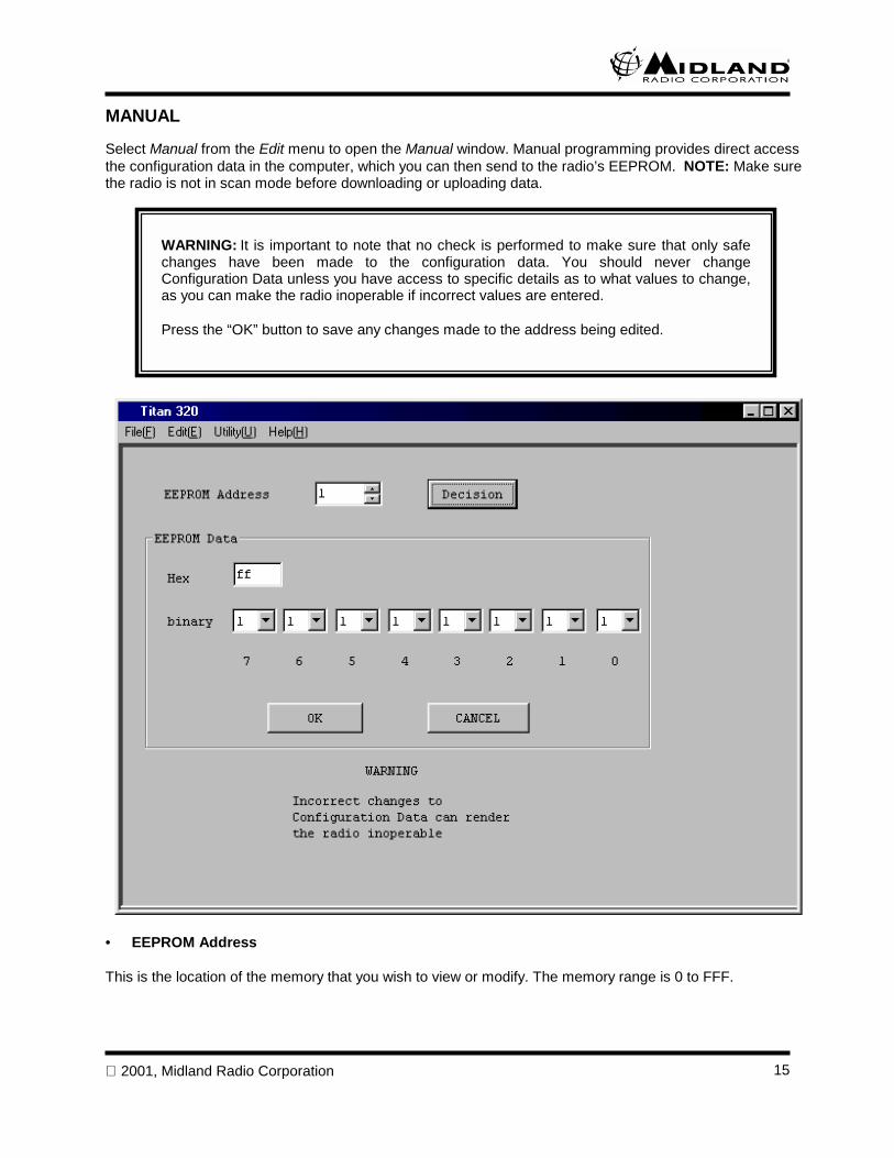
MANUAL
Select Manual from the Edit menu to open the Manual window. Manual programming provides direct accessthe configuration data in the computer, which you can then send to the radio’s EEPROM. NOTE: Make surethe radio is not in scan mode before downloading or uploading data.
• EEPROM Address
This is the location of the memory that you wish to view or modify. The memory range is 0 to FFF.
WARNING: It is important to note that no check is performed to make sure that only safechanges have been made to the configuration data. You should never changeConfiguration Data unless you have access to specific details as to what values to change,as you can make the radio inoperable if incorrect values are entered.
Press the “OK” button to save any changes made to the address being edited.

2001, Midland Radio Corporation16
• Decision Button
Click on the Decision button to view the EEPROM data at the address in the EEPROM Address window.
• EEPROM Data
The EEPROM data may be entered as a hex number (0—FF) or a binary number (00000000—11111111).Press the OK button to save any changes to the data.
2001, Midland Radio Corporation 17
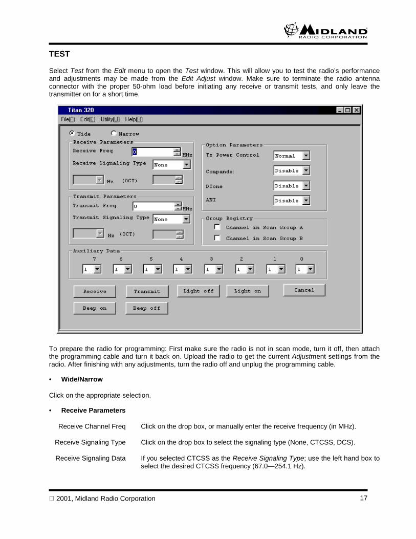
TEST
Select Test from the Edit menu to open the Test window. This will allow you to test the radio’s performanceand adjustments may be made from the Edit Adjust window. Make sure to terminate the radio antennaconnector with the proper 50-ohm load before initiating any receive or transmit tests, and only leave thetransmitter on for a short time.
To prepare the radio for programming: First make sure the radio is not in scan mode, turn it off, then attachthe programming cable and turn it back on. Upload the radio to get the current Adjustment settings from theradio. After finishing with any adjustments, turn the radio off and unplug the programming cable.
• Wide/Narrow
Click on the appropriate selection.
• Receive Parameters
Receive Channel Freq Click on the drop box, or manually enter the receive frequency (in MHz).
Receive Signaling Type Click on the drop box to select the signaling type (None, CTCSS, DCS).
Receive Signaling Data If you selected CTCSS as the Receive Signaling Type; use the left hand box toselect the desired CTCSS frequency (67.0—254.1 Hz).
2001, Midland Radio Corporation18
If you selected DCS as the Receive Signaling Type, use the right box to selectthe desired DCS code (0 to 777).
• Transmit Parameters
Transmit Channel Freq Click on the drop box, or manually enter the transmit frequency (in MHz).
Transmit Signaling Type Click on the drop box to select the signaling type (None, CTCSS, DCS).
Transmit Signaling Data If you selected CTCSS as the Transmit Signaling Type; use the left hand box toselect the desired CTCSS frequency (67.0—254.1 Hz).
If you selected DCS as the Transmit Signaling Type, use the right box to selectthe desired DCS code (0 to 777).
• Option Parameters
TX Power Click on the drop box to select Low or Normal power level.
Compander Click on the drop box to Enable or Disable compander operation.
Dtone Click on the drop box to Enable or Disable 2 Tone operation.
ANI Click on the drop box to Enable or Disable ANI operation.
• Group Registry
Channel in Scan Group A Click to put the channel in scan group A.
Channel in Scan Group B Click to put the channel in scan group B.
• Auxiliary Data
Click on the drop box and select either 0 or 1 for each of the 8 bits of auxiliary data.
• Buttons
Receive Button Click on this button to initiate a receive test.
Transmit Button Click on this button to initiate a transmit test.
Light (LCD) On Start light test.
Light (LCD) Off End light test.
Beep On Start beep test.
Beep Off Stop beep test.
Cancel Cancel the test mode.
Write Sends the data to the radio’s EEPROM.
2001, Midland Radio Corporation 19
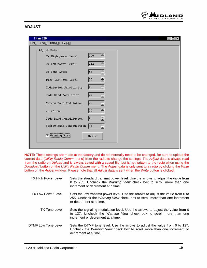
ADJUST
NOTE: These settings are made at the factory and do not normally need to be changed. Be sure to upload thecurrent data (Utility Radio Comm menu) from the radio to change the settings. The Adjust data is always readfrom the radio on Upload and is always saved with a saved file, but is not written to the radio when using theDownload button on the Utility Radio Comm menu. The Adjust data is only sent to a radio by clicking the Writebutton on the Adjust window. Please note that all Adjust data is sent when the Write button is clicked.
TX High Power Level Sets the standard transmit power level. Use the arrows to adjust the value from0 to 255. Uncheck the Warning View check box to scroll more than oneincrement or decrement at a time.
TX Low Power Level Sets the low transmit power level. Use the arrows to adjust the value from 0 to255. Uncheck the Warning View check box to scroll more than one incrementor decrement at a time.
TX Tone Level Sets the signaling modulation level. Use the arrows to adjust the value from 0to 127. Uncheck the Warning View check box to scroll more than oneincrement or decrement at a time.
DTMF Low Tone Level Sets the DTMF tone level. Use the arrows to adjust the value from 0 to 127.Uncheck the Warning View check box to scroll more than one increment ordecrement at a time.
2001, Midland Radio Corporation20
Modulation Sensitivity Sets the microphone sensitivity. Use the arrows to adjust the value from 0 to15. Uncheck the Warning View check box to scroll more than one increment ordecrement at a time.
Wide Band Modulation Sets the maximum modulation sensitivity for wideband. Use the arrows toadjust the value from 0 to 31. Uncheck the Warning View check box to scrollmore than increment or decrement at a time.
Narrow Band Modulation Sets the maximum modulation sensitivity for narrow band. Use the arrows toadjust the value from 0 to 31. Uncheck the Warning View check box to scrollmore than increment or decrement at a time.
The wide and narrow band settings may be used to change the perceivedtransmit audio balance when switching between narrow and wide bandchannels.
SQ Volume Sets the initial squelch level after programming. This is the same setting that isadjusted by the user on the channel knob menus. Use the arrows to adjust thevalue from 0 to 80.
Wide Band Demodulation Sets the demodulation sensitivity for channels programmed as wide band. Usethe arrows to adjust the value from 0 to 15.
Narrow Band Demodulation Sets the demodulation sensitivity for channels programmed as narrow band.Use the arrows to adjust the value from 0 to 15.
The wide and narrow band settings may be used to change the perceivedreceive audio balance when switching between narrow and wide bandchannels.
Click the Write button to write any adjustment data changes into the radio’s EEPROM. If adjustments aremade without clicking the Write button, the original adjustment data settings will be restored after the radio isturned off.
2001, Midland Radio Corporation 21
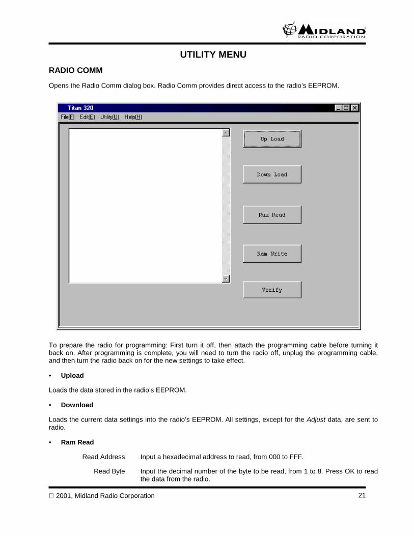
UTILITY MENURADIO COMM
Opens the Radio Comm dialog box. Radio Comm provides direct access to the radio’s EEPROM.
To prepare the radio for programming: First turn it off, then attach the programming cable before turning itback on. After programming is complete, you will need to turn the radio off, unplug the programming cable,and then turn the radio back on for the new settings to take effect.
• Upload
Loads the data stored in the radio’s EEPROM.
• Download
Loads the current data settings into the radio’s EEPROM. All settings, except for the Adjust data, are sent toradio.
• Ram Read
Read Address Input a hexadecimal address to read, from 000 to FFF.
Read Byte Input the decimal number of the byte to be read, from 1 to 8. Press OK to readthe data from the radio.
2001, Midland Radio Corporation22
• Ram Write
Write Address Input a hexadecimal address to write, from 000 to FFF.
Write Byte Input the decimal number of the byte to be written, from 1 to 8. Press OK towrite the data to the radio.
• Verify
Compare the contents of the radio’s EEPROM to the data settings in the computer.
If different data is found, the address and data are indicated. Press Continue to compare the remaining data,or Finish to end Verify.
Press OK to Copy the data from the radio’s EEPROM to the PC.
COMPORT SET
Select COM1 or COM2. The value you choose will be saved in the config file by the program.
WARNING: It is important to note that no check is performed to make sure that only safechanges have been made to the configuration data. You should never changeConfiguration Data unless you have access to specific details as to what values to change,as you can make the radio inoperable if incorrect values are entered.
Be sure any changes you make are correct before downloading the new data to the radio.
2001, Midland Radio Corporation 23
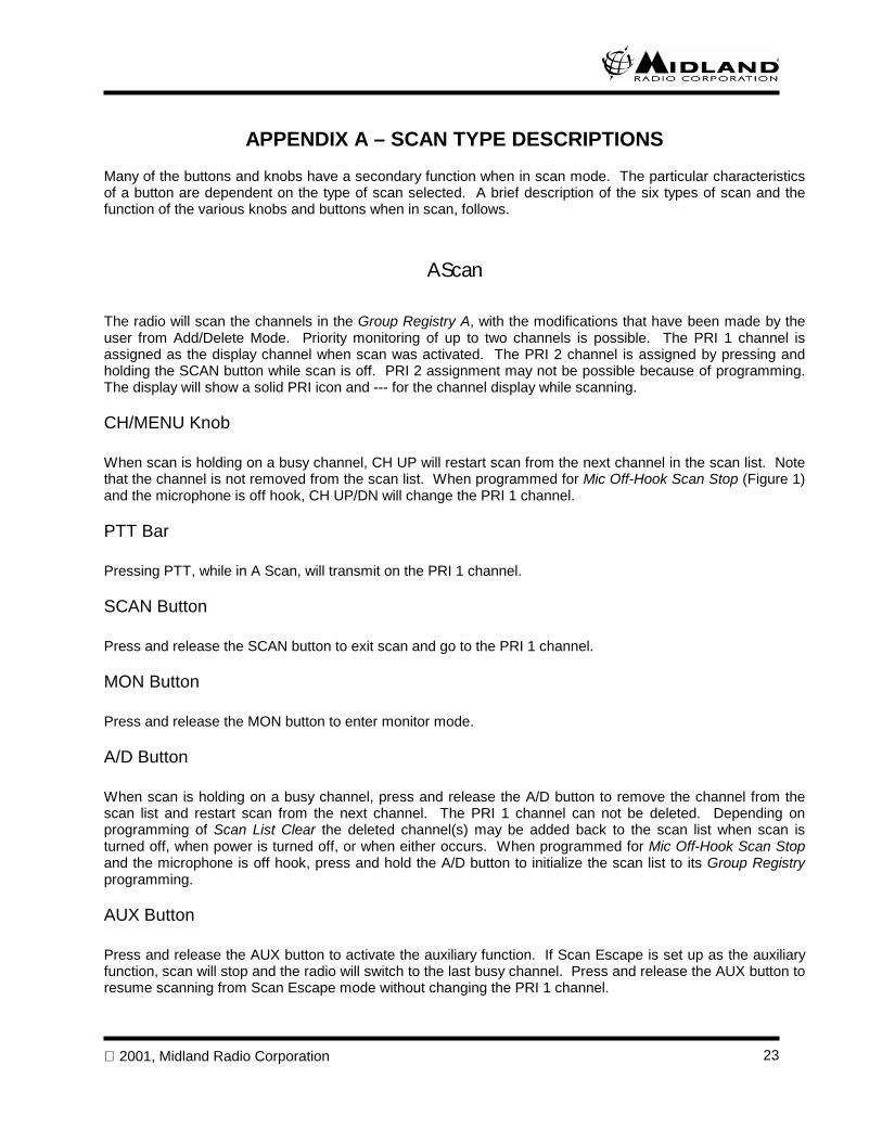
APPENDIX A – SCAN TYPE DESCRIPTIONSMany of the buttons and knobs have a secondary function when in scan mode. The particular characteristicsof a button are dependent on the type of scan selected. A brief description of the six types of scan and thefunction of the various knobs and buttons when in scan, follows.
A Scan
The radio will scan the channels in the Group Registry A, with the modifications that have been made by theuser from Add/Delete Mode. Priority monitoring of up to two channels is possible. The PRI 1 channel isassigned as the display channel when scan was activated. The PRI 2 channel is assigned by pressing andholding the SCAN button while scan is off. PRI 2 assignment may not be possible because of programming.The display will show a solid PRI icon and --- for the channel display while scanning.
CH/MENU Knob
When scan is holding on a busy channel, CH UP will restart scan from the next channel in the scan list. Notethat the channel is not removed from the scan list. When programmed for Mic Off-Hook Scan Stop (Figure 1)and the microphone is off hook, CH UP/DN will change the PRI 1 channel.
PTT Bar
Pressing PTT, while in A Scan, will transmit on the PRI 1 channel.
SCAN Button
Press and release the SCAN button to exit scan and go to the PRI 1 channel.
MON Button
Press and release the MON button to enter monitor mode.
A/D Button
When scan is holding on a busy channel, press and release the A/D button to remove the channel from thescan list and restart scan from the next channel. The PRI 1 channel can not be deleted. Depending onprogramming of Scan List Clear the deleted channel(s) may be added back to the scan list when scan isturned off, when power is turned off, or when either occurs. When programmed for Mic Off-Hook Scan Stopand the microphone is off hook, press and hold the A/D button to initialize the scan list to its Group Registryprogramming.
AUX Button
Press and release the AUX button to activate the auxiliary function. If Scan Escape is set up as the auxiliaryfunction, scan will stop and the radio will switch to the last busy channel. Press and release the AUX button toresume scanning from Scan Escape mode without changing the PRI 1 channel.
2001, Midland Radio Corporation24
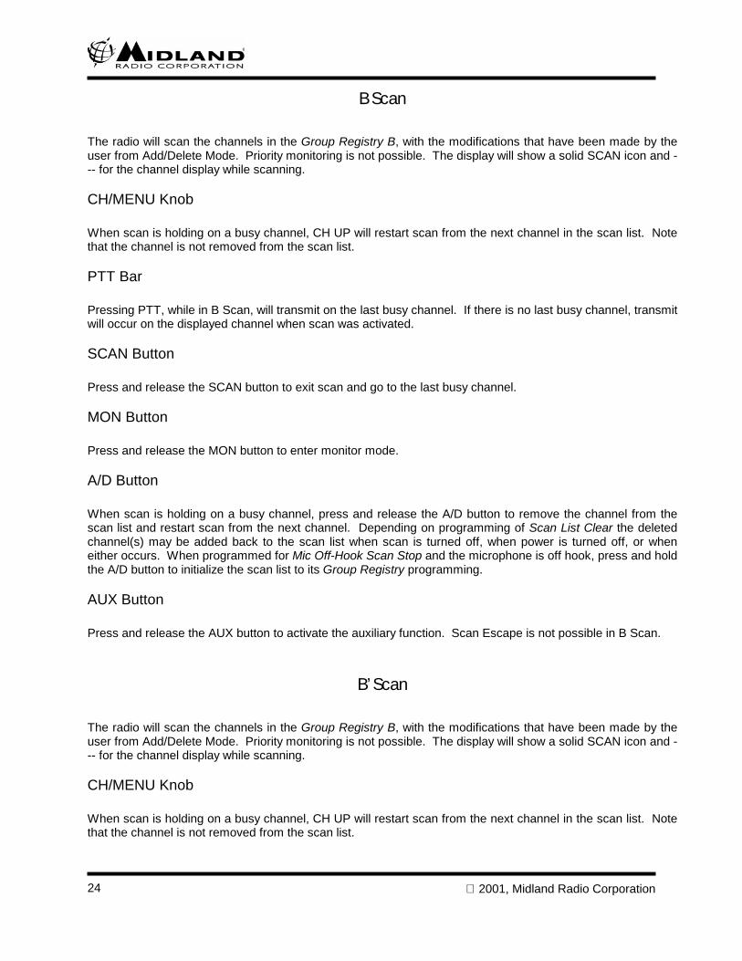
B Scan
The radio will scan the channels in the Group Registry B, with the modifications that have been made by theuser from Add/Delete Mode. Priority monitoring is not possible. The display will show a solid SCAN icon and --- for the channel display while scanning.
CH/MENU Knob
When scan is holding on a busy channel, CH UP will restart scan from the next channel in the scan list. Notethat the channel is not removed from the scan list.
PTT Bar
Pressing PTT, while in B Scan, will transmit on the last busy channel. If there is no last busy channel, transmitwill occur on the displayed channel when scan was activated.
SCAN Button
Press and release the SCAN button to exit scan and go to the last busy channel.
MON Button
Press and release the MON button to enter monitor mode.
A/D Button
When scan is holding on a busy channel, press and release the A/D button to remove the channel from thescan list and restart scan from the next channel. Depending on programming of Scan List Clear the deletedchannel(s) may be added back to the scan list when scan is turned off, when power is turned off, or wheneither occurs. When programmed for Mic Off-Hook Scan Stop and the microphone is off hook, press and holdthe A/D button to initialize the scan list to its Group Registry programming.
AUX Button
Press and release the AUX button to activate the auxiliary function. Scan Escape is not possible in B Scan.
B’ Scan
The radio will scan the channels in the Group Registry B, with the modifications that have been made by theuser from Add/Delete Mode. Priority monitoring is not possible. The display will show a solid SCAN icon and --- for the channel display while scanning.
CH/MENU Knob
When scan is holding on a busy channel, CH UP will restart scan from the next channel in the scan list. Notethat the channel is not removed from the scan list.
2001, Midland Radio Corporation 25
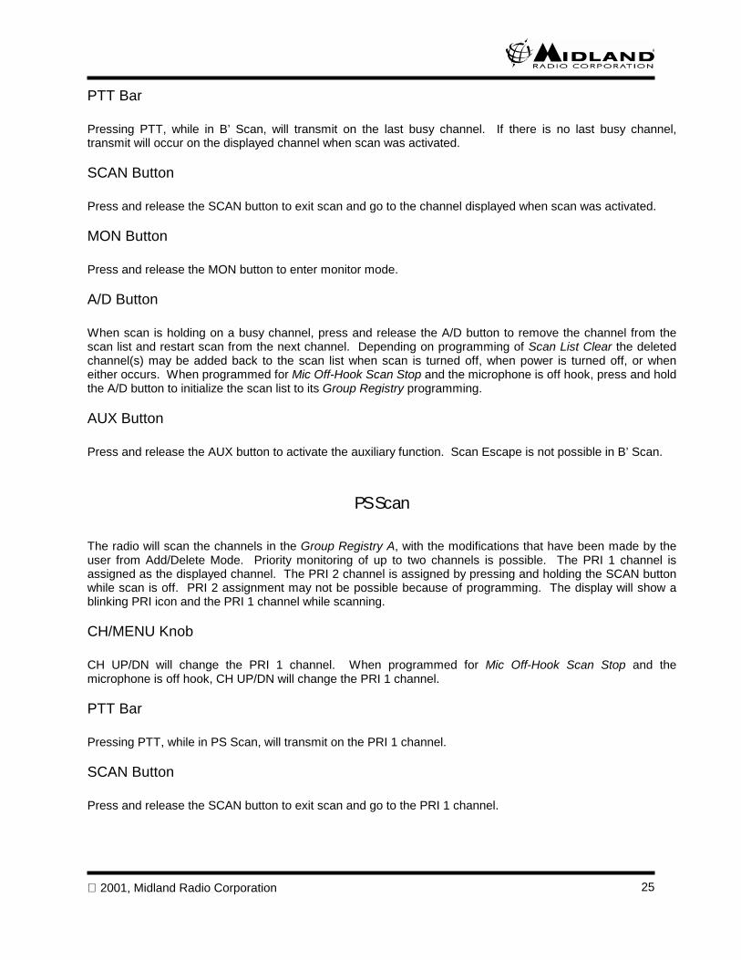
PTT Bar
Pressing PTT, while in B’ Scan, will transmit on the last busy channel. If there is no last busy channel,transmit will occur on the displayed channel when scan was activated.
SCAN Button
Press and release the SCAN button to exit scan and go to the channel displayed when scan was activated.
MON Button
Press and release the MON button to enter monitor mode.
A/D Button
When scan is holding on a busy channel, press and release the A/D button to remove the channel from thescan list and restart scan from the next channel. Depending on programming of Scan List Clear the deletedchannel(s) may be added back to the scan list when scan is turned off, when power is turned off, or wheneither occurs. When programmed for Mic Off-Hook Scan Stop and the microphone is off hook, press and holdthe A/D button to initialize the scan list to its Group Registry programming.
AUX Button
Press and release the AUX button to activate the auxiliary function. Scan Escape is not possible in B’ Scan.
PS Scan
The radio will scan the channels in the Group Registry A, with the modifications that have been made by theuser from Add/Delete Mode. Priority monitoring of up to two channels is possible. The PRI 1 channel isassigned as the displayed channel. The PRI 2 channel is assigned by pressing and holding the SCAN buttonwhile scan is off. PRI 2 assignment may not be possible because of programming. The display will show ablinking PRI icon and the PRI 1 channel while scanning.
CH/MENU Knob
CH UP/DN will change the PRI 1 channel. When programmed for Mic Off-Hook Scan Stop and themicrophone is off hook, CH UP/DN will change the PRI 1 channel.
PTT Bar
Pressing PTT, while in PS Scan, will transmit on the PRI 1 channel.
SCAN Button
Press and release the SCAN button to exit scan and go to the PRI 1 channel.
2001, Midland Radio Corporation26
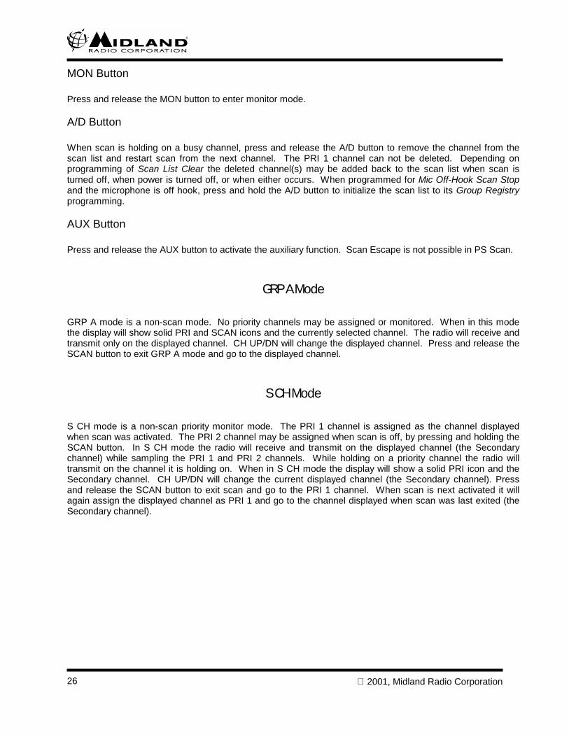
MON Button
Press and release the MON button to enter monitor mode.
A/D Button
When scan is holding on a busy channel, press and release the A/D button to remove the channel from thescan list and restart scan from the next channel. The PRI 1 channel can not be deleted. Depending onprogramming of Scan List Clear the deleted channel(s) may be added back to the scan list when scan isturned off, when power is turned off, or when either occurs. When programmed for Mic Off-Hook Scan Stopand the microphone is off hook, press and hold the A/D button to initialize the scan list to its Group Registryprogramming.
AUX Button
Press and release the AUX button to activate the auxiliary function. Scan Escape is not possible in PS Scan.
GRP A Mode
GRP A mode is a non-scan mode. No priority channels may be assigned or monitored. When in this modethe display will show solid PRI and SCAN icons and the currently selected channel. The radio will receive andtransmit only on the displayed channel. CH UP/DN will change the displayed channel. Press and release theSCAN button to exit GRP A mode and go to the displayed channel.
S CH Mode
S CH mode is a non-scan priority monitor mode. The PRI 1 channel is assigned as the channel displayedwhen scan was activated. The PRI 2 channel may be assigned when scan is off, by pressing and holding theSCAN button. In S CH mode the radio will receive and transmit on the displayed channel (the Secondarychannel) while sampling the PRI 1 and PRI 2 channels. While holding on a priority channel the radio willtransmit on the channel it is holding on. When in S CH mode the display will show a solid PRI icon and theSecondary channel. CH UP/DN will change the current displayed channel (the Secondary channel). Pressand release the SCAN button to exit scan and go to the PRI 1 channel. When scan is next activated it willagain assign the displayed channel as PRI 1 and go to the channel displayed when scan was last exited (theSecondary channel).
2001, Midland Radio Corporation 27
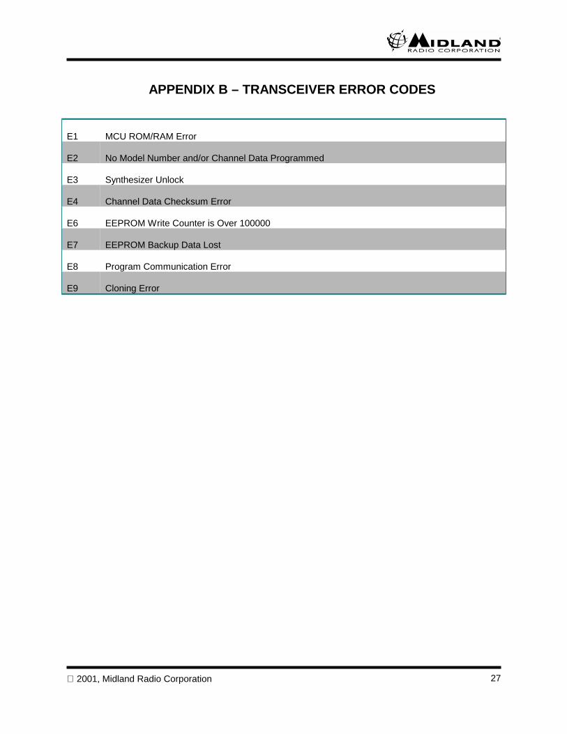
APPENDIX B – TRANSCEIVER ERROR CODES
E1 MCU ROM/RAM Error
E2 No Model Number and/or Channel Data Programmed
E3 Synthesizer Unlock
E4 Channel Data Checksum Error
E6 EEPROM Write Counter is Over 100000
E7 EEPROM Backup Data Lost
E8 Program Communication Error
E9 Cloning Error


1120 CLAY ST. •••• NORTH KANSAS CITY •••• MISSOURI •••• 64116TELEPHONE: 816 241 8500 •••• FAX: 816 241 5713
www.midlandradio.com