Embed Size (px)
Citation preview
Thermal energy storagefor renewable heating andcooling systems
7Luisa F. Cabeza, Eduard Or�o*GREA Innovaci�o Concurrent, Universitat de Lleida, Edifici CREA, Lleida, Spain
7.1 Introduction
7.1.1 Thermal energy storage
7.1.1.1 Principles and requirements
Thermal energy storage (TES) allows the storage of heat and cold for later use. TES isalso known as heat or cold storage (Mehling and Cabeza, 2008; Cabeza, 2012). TEScan aid in the efficient use and provision of thermal energy whenever there is amismatch between energy generation and use. This mismatch can be in terms oftime, temperature, power, or site (Dincer and Rosen, 2002). The potential advantageson the overall system performance are as follows (Mehling and Cabeza, 2008):
• Better economics—reducing investment and running costs• Better efficiency—achieving a more efficient use of energy• Less pollution of the environment and fewer CO2 emissions• Better system performance and reliability
The basic principle is the same in all TES applications. Energy is supplied to a stor-age system for removal and use at a later time (Dincer and Rosen, 2002). A completeprocess involves three steps (Figure 7.1): charging, storing, and discharging. In prac-tical systems, some of the steps may occur simultaneously, and each step can happenmore than once in each storage cycle (Gil et al., 2010).
Several factors have to be taken into consideration when deciding on the typeand the design of any thermal storage system, and a key issue is its thermalcapacity. However, selection of an appropriate system depends on many factors,such as costebenefit considerations, technical criteria, and environmental criteria(Gil et al., 2010; Cabeza, 2012).
Recently, storage concepts have been classified as active or passive systems (Gilet al., 2010). An active storage system is mainly characterized by forced-convectionheat transfer into the storage material. The storage medium itself circulates through
* Current address: Catalonia Institute for Energy Research, IREC, Jardins de les Dones de Negre, Sant Adri�ade Bes�os, Barcelona, Spain.
Renewable Heating and Cooling. http://dx.doi.org/10.1016/B978-1-78242-213-6.00007-2Copyright © 2016 Elsevier Ltd. All rights reserved.

a heat exchanger (the heat exchanger can also be a solar receiver or a steam generator).This system uses one or two tanks as storage media. Active systems are subdividedinto direct and indirect systems. In a direct system, the heat transfer fluid (HTF)serves also as the storage medium, whereas in an indirect system, a second mediumis used for storing the heat. Passive storage systems are generally dual-medium stor-age systems: the HTF passes through the storage only for charging and discharging asolid material.
The cost of a TES system mainly depends on the following items: the storage ma-terial itself, the heat exchanger for charging and discharging the system, and the cost ofthe space and/or enclosure for the TES.
From a technical point of view, the most important requirements are as follows:
• High energy density in the storage material (storage capacity)• Good heat transfer between HTF and storage medium (efficiency)• Mechanical and chemical stability of storage material (must support several charginge
discharging cycles)• Compatibility between HTF, heat exchanger, and/or storage medium (safety)• Complete reversibility of a number of chargingedischarging cycles (lifetime)• Low thermal losses• Easy control
And the most important design criteria from the point of view of technology are:
• Operation strategy• Maximum load• Nominal temperature and specific enthalpy drop in load• Integration into the whole application system
7.1.1.2 Design of storages
Figure 7.2 shows the basic working scheme of heat storage: heat or cold supplied by aheat source is transferred to the heat storage, stored in the storage, and later transferredto a heat sink to cope with the demand (Mehling and Cabeza, 2008).
Charging Storing Discharging
Figure 7.1 Steps involved in a complete TES system: charging, storing, and discharging(Gil et al., 2010).
140 Renewable Heating and Cooling

Every application sets a number of boundary conditions, which must be carefullyexamined:
• From the temperature point of view, the supply temperature at the source has to be higher orequal to the temperature of the storage and the storage to the sink.
• From the power point of view—that is, the amount of heat transferred in a certain time mustbe that required in the charging and discharging.
• In some applications, the HTF and its movement by free or forced convection have to beconsidered.
There are three basic design options in storage systems (Mehling and Cabeza,2008). The first one is when heat is exchanged by heat transfer on the surface of thestorage. This becomes a typical heat transfer problem in which heat transfer resistanceon the surface of the storage tank is the main parameter. Conduction and free or forcedconvection mechanisms are to be considered here.
Second, when a heat exchanger is used separating the HTF with the storage mate-rial, the surface of heat transfer increases significantly. This surface can be increasedeven further with the use of fins.
Finally, a third scheme is used when the heat storage medium is also the heat trans-fer medium. An example is when a water tank is discharged due to the demand of theshower, and cold water enters the tank replacing the hot one. In this case, heat transferis basically by convection.
7.1.1.3 Integration of storage into systems
The main goal to integrate a heat or cold storage tank into a system is to supply heat orcold. However, the different supply and demand situations have a great influence onthe integration concept (Mehling and Cabeza, 2008). The first case to consider iswhen there is no overlap in time between loading from the supply and unloading tothe demand. In this case, the storage system can match different times of supplyand demand; in many cases, the storage system can match different supply and demandpower, and even supply and demand location, with transport of the storage medium. Ifthere is a partial or total overlap in time, it is possible to smooth out fluctuations of thesupply and/or the demand. Thus, the typical goals of storage integration are tempera-ture regulation and power matching. The basic goals of the storage are to match supply
Heatsource
Heatsink
Heat
Storage Storage Storage
Figure 7.2 Basic working scheme of storage: heat or cold from a source is transferred to thestorage, stored in the storage, and later transferred to a sink (Mehling and Cabeza, 2008).
Thermal energy storage for renewable heating and cooling systems 141

and demand regarding the amount of heat and cold and the heating or cooling power atthe right time. Although the amount of heat or cold is determined by the size of thestorage and the heating or cooling power, which depend mainly on the design of thestorage, the integration concept has a large influence with respect to time.
7.1.2 Methods for TES
7.1.2.1 Sensible heat storage
In sensible TES, energy is stored by changing the temperature of a storage medium suchas water, air, oil, rock beds, bricks, concrete, or sand. The amount of energy introducedto the storage system is proportional to the temperature lift, the mass of the storagemedium, and the heat capacity of the storage medium. Each medium or material hasits own advantages and disadvantages, but usually its selection is based on the heatcapacity and the available space for storage (Dincer and Rosen, 2002). The amountof heat stored in a material, Q, can be expressed as:
Q ¼ m$cp$DT
in which m is the mass of storage material (kg), cp is the specific heat of the storagematerial (J kg�1 �C�1), DT is the temperature change (�C).
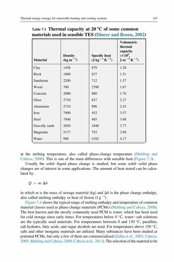
Sensible storage is the most common method of heat and cold storage. Some com-mon materials used in TES systems are presented in Table 7.1 (Dincer and Rosen,2002). The material must be inexpensive and should have good thermal capacity(r cp, r is the density) to be useful in a storage application.
Besides the density and the specific heat of the storage material, other propertiesthat are also important for sensible heat storage are operational temperatures, thermalconductivity and diffusivity, vapor pressure, compatibility among materials, stability,heat loss coefficient as a function of the surface area-to-volume ratio, and cost(Gil et al., 2010).
A sensible TES system consists of a storage medium, a container (commonly, atank), and inleteoutlet devices. Tanks must retain the storage material and preventlosses of thermal energy. The existence of a thermal gradient across storage is desirable(Gil et al., 2010). Sensible heat storage can be made from solid or liquid media. Solidmedia are usually used in packed beds, requiring a fluid to exchange heat. When thefluid is a liquid, the heat capacity of the solid in the packed bed is not negligible, andthe system is called a dual-storage system.
In heating and cooling of buildings, sensible TES is mostly used for domestic hotwater, in combisystems (Hadorn, 2005), and for seasonal energy storage.
7.1.2.2 Latent heat storage
When a material stores heat while at phase transition, the heat is stored as latent heat.The solideliquid phase change process by melting and solidification can store largeamounts of heat and cold if a suitable material is selected. Upon melting, while heatis transferred to the storage material, the material still keeps its temperature constant
142 Renewable Heating and Cooling
at the melting temperature, also called phase-change temperature (Mehling andCabeza, 2008). This is one of the main differences with sensible heat (Figure 7.3).
Usually the solideliquid phase change is studied, but some solidesolid phasechanges are of interest in some applications. The amount of heat stored can be calcu-lated by:
Q ¼ m$Dh
in which m is the mass of storage material (kg) and Dh is the phase change enthalpy,also called melting enthalpy or heat of fusion (J g�1).
Figure 7.4 shows the typical range of melting enthalpy and temperature of commonmaterial classes used as phase-change materials (PCMs) (Mehling and Cabeza, 2008).The best known and the mostly commonly used PCM is water, which has been usedfor cold storage since early times. For temperatures below 0 �C, wateresalt solutionsare the typically used materials. For temperatures between 0 and 130 �C, paraffins,salt hydrates, fatty acids, and sugar alcohols are used. For temperatures above 150 �C,salts and other inorganic materials are utilized. Many substances have been studied aspotential PCMs, but only a few of them are commercialized (Zalba et al., 2003; Cabeza,2005;Mehling and Cabeza, 2008; Cabeza et al., 2011). The selection of thematerial to be
Table 7.1 Thermal capacity at 20 8C of some commonmaterials used in sensible TES (Dincer and Rosen, 2002)
MaterialDensity(kg mL3)
Specific heat(J kgL1 KL1)
Volumetricthermalcapacity(3106,J mL3 KL1)
Clay 1458 879 1.28
Brick 1800 837 1.51
Sandstone 2200 712 1.57
Wood 700 2390 1.67
Concrete 2000 880 1.76
Glass 2710 837 2.27
Aluminum 2710 896 2.43
Iron 7900 452 3.57
Steel 7840 465 3.68
Gravelly earth 2050 1840 3.77
Magnetite 5177 752 3.89
Water 988 4182 4.17
Thermal energy storage for renewable heating and cooling systems 143

used in latent heat storage is not easy.Availability and cost are usually themaindrawbacksfor the selection of a technically suitablematerial. Still today, problems such as phase sep-aration, subcooling, corrosion, long-term stability, and low heat conductivity have notbeen totally solved and are under research.
Salt hydrateseutectic
Water Sugaralcohols
Fatty acidsPolyethylene
glycols
Clathrates
Nitrates
HydroxidesChlorides
Carbonates Fluorides
Paraffins
0.1 MWh m–3
Melting temperature (°C)
Mel
ting
enth
alpy
(MJ
m–3
)
+200 +300 +400 +500 +600 +700 +800+100
100
200
300
400
500
600
700
800
900
00–100
Water-saltsolutions
Figure 7.4 Classes of materials that can be used as PCMs and their typical range of meltingtemperature and melting enthalpy (Mehling and Cabeza, 2008).
Phase changetemperature
Stored heat
Temperature profileof latent TESTemperature profile
of sensibleTESTe
mpe
ratu
re
Figure 7.3 Heat storage as sensible and latent TES.
144 Renewable Heating and Cooling

PCMs must have a large latent heat and high thermal conductivity, but the mostimportant selection parameter is that the melting temperature of the materials lies inthe practical range of operation. Other parameters are congruent melting, minimumsubcooling, chemical stability, low cost, nontoxicity, and noncorrosivity. Materialsthat have been studied are paraffin waxes, fatty acids, and eutectics of organic andnonorganic compounds (Farid et al., 2004; Sharma et al., 2009). Tables 7.2 and 7.3show two comparisons between organic and inorganic PCMs (Zalba et al., 2003;Mehling and Cabeza, 2008; Rathod and Banerjee, 2013).
According to Kenisarin and Mahkamov (2007), the following PCM properties to beused for latent heat storage were highlighted as desirable:
• High value of the heat of fusion and specific heat per unit volume and weight• Melting point that matches the application• Low vapor pressure (<1 bar) at the operational temperature• Chemical stability and noncorrosiveness• Not hazardous, highly inflammable, or poisonous• Reproducible crystallization without degradation• Small subcooling degree and high rate of crystal growth• Small volume variation during solidification• High thermal conductivity• Availability and abundance
Paraffins are a mixture of pure alkanes that have quite a wide range of the phase-change temperature. These paraffins also have low thermal conductivity comparedto inorganic materials, and therefore the choice of those which can be used for practicalsolar applications is very limited.
Commercial paraffin waxes are cheap with moderate thermal storage densities(w200 kJ kg�1 or 150 MJ m�3) and a wide range of melting temperatures. They
Table 7.2 Comparison of organic and inorganic materials for heatstorage (Zalba et al., 2003; Mehling and Cabeza, 2008)
Organic Inorganic
Advantages No corrosives Greater phase change enthalpy
Low or nosubcooling
Chemical stability
Disadvantages Lower phasechange enthalpy
Subcooling
Low thermalconductivity
Corrosion
Flammability Phase separation
Phase segregation, lack of thermal stability
Thermal energy storage for renewable heating and cooling systems 145

Table 7.3 Comparison of PCM types
Organic Inorganic
EutecticsParaffins Fatty acids Salt hydrates Metals
Formula CnH2nþ2
(n ¼ 12e38)CH3(CH2)$COOH AB$nH2O e e
Melting point �12e71 �C 7.8e187 �C 11e120 �C 30e96 �C 4e93 �C
Melting enthalpy 190e260 kJ kg�1 130e250 kJ kg�1 100e200 kJ kg�1 25e90 kJ kg�1 100e230 kJ kg�1
Cost Expensive 2 to 3 times moreexpensive thanparaffins
Low cost Costly Costly
Adapted from Rathod and Banerjee (2013).
146Renew
ableHeating
andCooling

undergo negligible subcooling and are chemically inert and stable with no phase segre-gation. However, they have low thermal conductivity (w0.2 W m�1 K�1), whichlimits their applications.
The main limitation of salt hydrates is their chemical instability when they are heat-ed, as at elevated temperatures they degrade, losing some water content every heatingcycle. Furthermore, some salts are chemically aggressive toward structural materials,and they have low heat conductivity. Finally, salt hydrates have a relatively high de-gree of subcooling.
Salt hydrates are attractive materials for use in TES due to their high volumetricstorage density (w350 MJ m�3), relatively high thermal conductivity compared toorganic materials (w0.5 W m�1 K�1), and moderate costs compared to paraffinwaxes, with few exceptions.
According to Cabeza et al. (2011), the PCM to be used in the design of a thermalstorage system should have desirable thermophysical, kinetic, and chemical propertiesand desired economics as listed below:
1. Thermophysical propertiesa. Melting temperature in the desired operating temperature range: to assure storage and
extraction of heat in an application with a fixed temperature rangeb. High latent heat of fusion per unit volume: to achieve high storage density compared to
sensible storagec. High specific heat to provide additional significant sensible heat storaged. High thermal conductivity of both solid and liquid phases to assist the charging and dis-
charging energy of the storage systeme. Small volume change on phase transformation and small vapor pressure at operating tem-
perature to reduce the containment problemf. Congruent melting of the PCM for a constant storage capacity of the material with each
freezing/melting cycleg. Reproducible phase change: to use the storage material many times (also called cycling
stability)2. Kinetic properties—nucleation and crystal growth
a. High nucleation rate to avoid supercooling of the liquid phase and to assure that meltingand solidification proceed at the same temperature
b. High rate of crystal growth, so that the system can meet demand of heat recovery from thestorage system
3. Chemical propertiesa. Complete reversible freeze/melt cycleb. No degradation after a large number of freeze/melt cyclesc. No corrosiveness to the construction materialsd. Nontoxic, nonflammable, and nonexplosive material for safety: for environmental and
safety reasons4. Economics
a. Abundantb. Availablec. Cost-effective: to be competitive with other options for heat and cold storage
For their use, PCMs must be encapsulated, either encapsulating the material orencapsulating the building composite, as otherwise the liquid phase would be ableto flow away from the location where it is applied.
Thermal energy storage for renewable heating and cooling systems 147

Latent heat storage is used in buildings both in passive and in active systems toreduce the energy demand of the building, to better use renewable energies (solar en-ergy), or for free cooling.
7.1.2.3 Thermochemical heat storage
Any chemical reaction with high heat of reaction can be used for TES if the products ofthe reaction can be stored and if the heat stored during the reaction can be releasedwhen the reverse reaction takes place (Mehling and Cabeza, 2008). A comparisonof the energy storage densities achieved with different methods of storage is shownin Table 7.4.
Higher energy storage density and reversibility are required on the materials forthermal energy conversion and storage (Kato, 2007). Energy density of chemicalchanges is relatively higher than that of physical changes. A merit of chemical energyconversion is the possession of efficient energy storage performance. The performanceis especially advantageous for TES. Chemical storage can store energy as reactantswith small loss. It is important to find the appropriate reversible chemical reactionfor the temperature range of subjected energy source.
TES can be realized by utilizing reversible chemical reactions (Hauer, 2007). Here,the process of adsorption on solid materials or absorption on liquids is explained.Adsorption means binding of a gaseous or liquid phase of a component on the innersurface of a porous material. During the desorption step, heat is put into the sample.The adsorbed component is removed from the inner surface. As soon as the reversereaction (adsorption) is started, the heat will be released. The adsorption step repre-sents the discharging process. There are two types of sorption systems, closed andopen storage systems. In a “closed sorption system,” the heat is transferred to andfrom the adsorbent by a heat exchanger, usually called condenser/evaporator. Theheat has to be transported to the absorber at the same time as it is extracted fromthe condenser to keep the HTF, usually water, flowing from the adsorber to thecondenser.
The mechanism of a sorption thermal storage process can be represented by:
A$ðmþ nÞBþ Heat 4 A$mBþ nB
in which A is the sorbent and B is the sorbate. A/B is called a sorption working pair.Although sorption thermal storage systems offer some benefits, there are still crit-
ical drawbacks, such as great complexity in the system configuration (for closed sys-tems), expensive investment, poor heat and mass transfer ability (for chemicalreaction), and low heat storage density in actual systems (Yu et al., 2013).
According to the system configuration, sorption storage systems can be divided intoopen and closed systems (Hauer, 2007; Yu et al., 2013). Closed sorption systems arenot in contact with the atmospheric environment and have been studied for refrigera-tion, heat pump systems, and energy storage applications (Figure 7.5). Closed systemsare adequate for small-scale applications, in which compact and highly efficient de-vices are needed. Open systems allow the release of the sorbate to the environment
148 Renewable Heating and Cooling
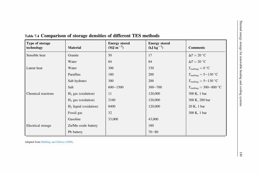
Table 7.4 Comparison of storage densities of different TES methods
Type of storagetechnology Material
Energy stored(MJ mL3)
Energy stored(kJ kgL1) Comments
Sensible heat Granite 50 17 DT ¼ 20 �C
Water 84 84 DT ¼ 20 �C
Latent heat Water 306 330 Tmelting ¼ 0 �C
Paraffins 180 200 Tmelting ¼ 5e130 �C
Salt hydrates 300 200 Tmelting ¼ 5e130 �C
Salt 600e1500 300e700 Tmelting ¼ 300e800 �C
Chemical reactions H2 gas (oxidation) 11 120,000 300 K, 1 bar
H2 gas (oxidation) 2160 120,000 300 K, 200 bar
H2 liquid (oxidation) 8400 120,000 20 K, 1 bar
Fossil gas 32 300 K, 1 bar
Gasoline 33,000 43,000
Electrical storage Zn/Mn oxide battery 180
Pb battery 70e80
Adapted from Mehling and Gabeza (2008).
Therm
alenergy
storagefor
renewable
heatingand
coolingsystem
s149
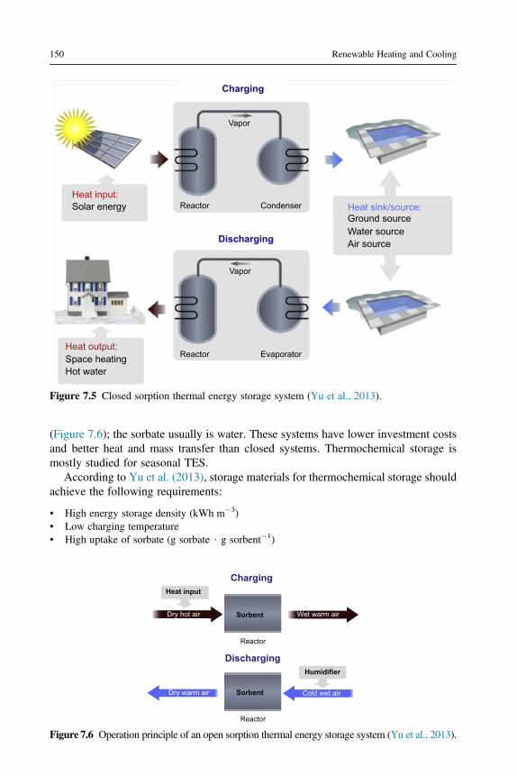
(Figure 7.6); the sorbate usually is water. These systems have lower investment costsand better heat and mass transfer than closed systems. Thermochemical storage ismostly studied for seasonal TES.
According to Yu et al. (2013), storage materials for thermochemical storage shouldachieve the following requirements:
• High energy storage density (kWh m�3)• Low charging temperature• High uptake of sorbate (g sorbate $ g sorbent�1)
Charging
Discharging
Vapor
ReactorHeat input:
Heat sink/source:Ground sourceWater sourceAir source
Solar energy
Heat output:Space heatingHot water
Vapor
Reactor
Condenser
Evaporator
Figure 7.5 Closed sorption thermal energy storage system (Yu et al., 2013).
Heat input
Charging
Discharging
Dry hot air Wet warm air
Reactor
Sorbent
Reactor
Sorbent
Humidifier
Cold wet airDry warm air
Figure 7.6 Operation principle of an open sorption thermal energy storage system (Yu et al., 2013).
150 Renewable Heating and Cooling

• Appropriate heat and mass transfer properties to ensure designed output power• Easy to handle, nonpoisonous• Low cost, low price per kWh heat energy stored• Thermal stability, no deterioration
The chemical sorption processes found in the literature are those between metal saltswith water, ammonia, methanol or methyl-ammonia, and metal alloys with hydrogen(Figure 7.7). Sorption enthalpy typically ranges between 20 and 70 kJ mol�1. A gooddescription of the specific reactants can be found in Cot-Gores et al. (2012).
7.2 Description of TES technologies used today and theirapplications in the context of renewable heatingand cooling
7.2.1 Passive systems in building skins
Passive use of PCMs in buildings has the objective to decrease the operation energy ofthe building by decreasing the energy demand of space heating and cooling, basically
Reactants
Sorption processes Chemical reactions
BaCl2MnCl2
MgCl2PbCl2CaCl2SrCl2CoCl2
NH4Cl2NaBr
NiCl2
MgSO4
Al2(SO4)3
MgCl2NaS
SrBr2
MnCl2
CaCl2
HydratesAmmoniates Metal hydrides Hydration Carbonation
MgOCaO
PbOCaO
Zr0.9 Ti0.1Cr0.6Fe1.4Zr0.9 Ti0.1Cr0.6Fe1.1LaNi4.6Mn0.3Al0.1
La0.6Y0.4Ni4.8Mn0.2MmNi4.5Al0.5
ZnMnFeLaNi4.7Al0.3
MmNi4.15Fe0.85LmNi4.85Sn0.15
LmNi4.49Co0.1Mn0.205Al0.205LmNi4.05Co0.2Mn0.62Al0.1
MmNi4.15Fe0.85LaNi4.85Al0.15
Ti0.99Zr0.01V0.43Fe0.09Cr0.05Mn1.5La0.555Co0.03Pr0.12Nd0.295Ni5
LaNi4.6Al0.4LaNi4.1Al0.52Mn0.38
LmNi4.91Sn0.15LaNi4.61Mn0.26Al0.13
LaNi5LaNi4.3Al0.4Mn0.3
LaNi4.4Al0.34Mn0.26LaNi4.5Al0.29Mn0.21
LaNi4.7Sn0.3LaNi4.75Al0.25
Ti0.98
Figure 7.7 Working pairs tested for thermochemical storage (Cot-Gores et al., 2012).
Thermal energy storage for renewable heating and cooling systems 151

smoothing the indoor temperature by increasing the energy inertia of the buildingenvelope.
One of the oldest options studied and published were PCM wallboards to improvethe thermal comfort of lightweight buildings (Sharma et al., 2009), because they arevery suitable for the incorporation of PCM (Soares et al., 2013). The efficiency of theseelements depends on several factors such as how the PCM is incorporated in the wall-board, the orientation of the wall, the climatic conditions, the direct solar gains, the in-ternal gains, the color of the surface, the ventilation rate, the PCM chosen, and itsphase-change temperature, the temperature range over which phase change occurs,and the latent heat capacity per unit area of the wall.
Schossig et al. (2005) showed that PCM can be impregnated into building ma-terials but that when added microencapsulated leakage problems disappear(Figure 7.8). Barreneche et al. (2013) compared in an interlaboratory test the threedifferent methods to incorporate PCM in building materials: microencapsulated,suspension, and impregnation. Although suspension allows the maximum amountof PCM in the building material, only microencapsulation ensures avoidingleakage.
An example of the use of PCM in wallboards was the development of the Dupontproduct Energain, studied and characterized in several papers (Kuznik et al.,2008a,b; Kuznik and Virgone, 2009; Kuznik et al., 2011). Kuznik et al. (2008a) per-formed an optimization process using interior/exterior temperature evolutions withina period of 24 h to optimize the thickness of a PCM wallboard to enhance the thermalbehavior of a lightweight internal partition wall. The PCM wallboard was composedof 60 wt% of microencapsulated paraffin, which has a melting temperature of about22 �C (Figure 7.9).
PCM wallboard is considered to be an effective and less costly replacement of stan-dard thermal mass to store solar heat in buildings, in which the PCM is imbedded into agypsum board, plaster, or other building structures. The thermal characteristics ofPCM wallboard are very close to those of PCMs alone, and when a PCM wallboard
Plaster
Microcapsules
Lightweight construction
Figure 7.8 Addition of microencapsulated PCMs in a lightweight building (Schossig et al., 2005).
152 Renewable Heating and Cooling

is cut, a greater concentration of PCM lies in the outer third of the wallboard thicknessnear each face due to the diffusion process (Athienitis et al., 1997).
Athienitis et al. (1997) used a gypsum board impregnated with a PCM in a direct-gain outdoor test room to investigate the thermal performance of PCM gypsum boardused in a passive solar building. The results showed that the room temperature can bereduced by a maximum 4 �C during the daytime. Neeper (2000) reported on theimpregnation of fatty acid and paraffin waxes into the gypsum wallboard and exami-nation of the thermal dynamics under the diurnal variation of room temperature (theradiation absorbed was not considered) with the PCM on the interior partition andon the exterior partition, respectively. The investigation indicated that when thePCM melting temperature was close to the average room temperature, the maximumdiurnal energy storage occurred and diurnal energy storage decreased if the phasechange transition occurred over a range of temperature.
To evaluate the capacity of PCM to stabilize the internal environment when therewere external temperature changes and solar radiations, Kuznik et al. (2008b)designed an experimental test room MINIBAT using a battery of 12 spotlights tosimulate an artificial sunning and they got the results that the PCM wallboard canreduce the air-temperature fluctuations in the room and enhance the natural convec-tion mixing of the air, avoiding uncomfortable thermal stratifications. Kuznik andVirgone (2009) also tested two identical test cells under two kinds of external tem-perature evolutions, heating and cooling steps with various slopes, and sinusoidaltemperature evolution with 24 h period. They found there was time lag between in-door and outdoor temperature evolutions and the external temperature amplitude inthe cell was reduced.
Figure 7.9 Dupont PCM composite wallboard (Kuznik et al., 2008a).
Thermal energy storage for renewable heating and cooling systems 153

Lv et al. (2006) built an ordinary room as well as a room using PCM gypsum wall-board in the northeast of China, and they found that the PCM wallboards can attenuateindoor air fluctuation, reduce the heat transfer to outdoor air, and have the function tokeep warm. Recently, Kuznik et al. (2011) used Dupont de Nemours PCM wallboardsfor the renovation of a tertiary building and found they were really efficient if theoutside temperature was varying in melting temperature by monitoring the buildingfor a whole year. Some researchers reported that using a vacuum isolation panel(VIP) in a wallboard can reduce the thermal loss and improve efficiency for light-weight buildings.
Two test cells were designed by Ahmad et al. (2006), and each cell consisted of oneglazed face and five opaque faces insulated with VIPs. One of the cells was equippedwith five PCM panels. The cross-structure with PCM wallboard and VIP is shown inFigure 7.10. The amplitude of temperature variation inside the cell with PCM panelswas decreased by 20 �C. So in the winter, it helped to efficiently prevent negative in-door temperature. The PCM panels still showed a good thermal storage capability evenafter more than 480 thermal cycles.
Mandilatas et al. (2013) present one of the first attempts to investigate the thermalperformance of a purposely built full-scale lightweight demonstration house con-structed in Greece that includes PCM gypsum boards in all external walls as well asin internal partitions of the building (Figures 7.11 and 7.12). Experimental resultsshow that the indoor air temperatures in all thermal zones examined (LVR, MBDR,BDR) do not significantly vary during a 24 h dayenight cycle and this can be attrib-uted to the house’s enhanced thermal mass associated with the insulation, as well aswith the absence of typical occupant behavior.
The use of PCM in building envelopes has been demonstrated in a long-term exper-imental study at the University of Lleida (Spain). Here, different forms of PCM havebeen tested in a pilot plant (Figure 7.13) in several identically shaped cubicles with in-ternal dimensions of 2.4 � 2.4 � 2.4 m. The cubicles were built using different typicalconstructive solutions so concrete cubicles (Cabeza et al., 2007), brick cubicles, and
Plywood 5 mm
PCM panel 25 mm
VIP 17 mm
Fibre cement 6 mmFigure 7.10 Cross-structure of PCMwallboard with vacuum isolation panel(VIP) (Ahmad et al., 2006).
154 Renewable Heating and Cooling

Figure 7.11 External view of a demonstration house including PCM wallboards (Mandilaraset al., 2013).
External wall cross section
EPSCementboard outdoor 12.5 mm
Gypsumboard 12.5 mm
Insulation 80 mm
PCM plasterboard 2 × 15 mm
Cementboard indoor2 × 12.5 mm
Cementboard indoor2 × 12.5 mm
Insulation 80 mm
Internal wall cross section
CB
SB
Int
Cav
(a)
(b)
Figure 7.12 Cross section of (a) the external wall (“CB,” “Cav,” “SB,” and “Int” correspond totemperature sensors placed in the LVR east wall); (b) the partition wall with cement boards(Mandilaras et al., 2013).
Thermal energy storage for renewable heating and cooling systems 155

alveolar brick cubicles (Castell et al., 2010) can be found. In this setup, free-floatingtemperature and controlled temperature experiments are carried out.
Castell�on et al. (2009) show different results of this experimental setup. As anexample, results from the brick cubicles are shown here. Figure 7.14 presents the re-sults for free-floating experiments in the brick cubicles, comparing the Reference, PU,and RT27 þ PU cubicles during a week in August 2008, when the PCM was workingwithin the phase-change range. As expected, the Reference cubicle always presentedhigher temperature oscillations and it was also more sensitive to the ambient temper-ature changes than the PU and RT27 þ PU cubicles. When comparing the PU and theRT27 þ PU cubicles, the temperature control achieved by the use of PCM wasobserved. The temperature of the RT27 þ PU cubicle remained closer to the phase-change range. The RT27 þ PU cubicle remained cooler (about 0.4 �C) during mostof the week, when the weather was warmer. At the end of the week (when the weatheris cooler) the tendency was reversed, with the PU cubicle being cooler than theRT27 þ PU cubicle. This behavior can be explained by the higher thermal mass ofthe PCM cubicle, which slows down the general cooling tendency that occurs in thelast days of the week. The effect of the PCM is also visible in the reduction in the dailyoscillations of the inside temperature in the RT27 þ PU cubicle. It is also observed thatthe effect of the PCM is only partially used, as there is no single 24 h period in whichfull melting and solidification are achieved.
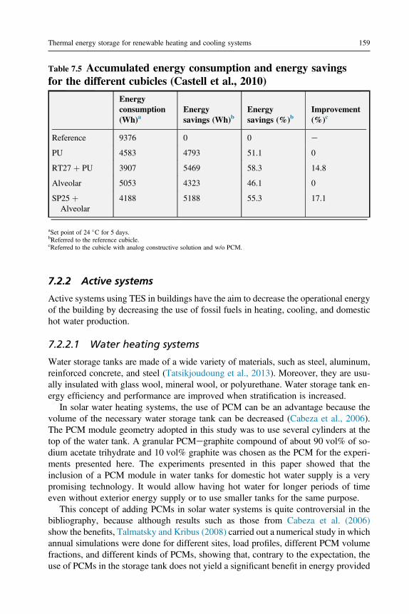
Figure 7.15 and Table 7.5 present the results of the controlled temperature experi-ments using a set point of 24 �C for a week in August, 2008. The accumulated energyconsumption of the Reference cubicle is much higher than all the other cubicles, withabout twice the consumption of the other cubicles. The RT27 þ PU cubicle is the onewith the lowest energy consumption, whereas the SP25 þ Alveolar cubicle is the sec-ond one, consuming even less energy than the PU cubicle. Finally, the Alveolarcubicle is the one that consumes more energy after the Reference cubicle. BothPCM cubicles reduced the energy consumption compared with the same cubiclewithout PCM. The RT27 þ PU cubicle achieved a reduction of 14.75% comparedwith the PU cubicle, whereas the SP25 þ Alveolar cubicle reached 17.12% of energysavings compared with the Alveolar cubicle (Table 7.5).
Investigations on PCM floors and PCM ceilings for passive solar heating have beencarried out during the past few years. Xu et al. (2005) used shape-stabilized PCMfloors in passive solar buildings and developed a model to analyze how variousfactors influence the thermal performance, such as thickness of PCM layer, melting
Figure 7.13 Experimental setup located in Puigverd de Lleida, Spain (Castell et al., 2010).
156 Renewable Heating and Cooling

temperature, heat of fusion, and thermal conductivity of PCM. They indicated thatthe heat of fusion and thermal conductivity of PCM should be larger than 120 kJ kg�1
and 0.5 W m�1 K�1 and that the thickness of shape-stabilized PCM plate should notbe larger than 20 mm. Pasupathy and Velraj (2008) studied the effect of the buildingwith a PCM panel on the roof from the aspect of the location and thickness. They rec-ommended a double-layer PCM to be incorporated in the roof to narrow indoor airtemperature variation and to better suit it for all seasons.
36
34
32
30
28
26
24
22
Tem
pera
ture
(°C
)
20
18
16
14
12
10
8
11/08/08 12/08/08
Phase change range Date
Outside
Inside RT27 + PU
Inside reference
RT-27
13/08/08 14/08/08 15/08/08 16/08/08 17/08/08 18/08/08 19/08/08
32
31
30
29
28
27
26
25
Tem
pera
ture
(°C
)
24
23
22
11/08/08 12/08/08
Date
Inside RT27 + PU
Inside PU
13/08/08 14/08/08 15/08/08 16/08/08 17/08/08 18/08/08 19/08/08
(a)
(b)
Figure 7.14 Brick cubicles free-floating experimentation: (a) Weather conditions and PCMoperating temperature; (b) indoor ambient temperature for Reference, PU, and RT27 þ PUcubicles (Castell�on et al., 2009).
Thermal energy storage for renewable heating and cooling systems 157

Many other examples of passive solar systems using PCM can be found in the liter-ature and summarized in the different reviews published (Zalba et al., 2003; Faridet al., 2004; Kenisarim and Mahkamov, 2007; Cabeza et al., 2011; Sharma et al.,2009; Rathod and Banerjee, 2013; Soares et al., 2013).
(a)
(b)
0
0
1
2
3
4
5
6
7
8
9
10
27/08/2008
27/08/2008
28/08/2008 29/08/2008
Date
Date
30/08/2008 31/08/2008
28/08/2008 29/08/2008 30/08/2008 31/08/2008
1
2
3
4
5
Energ
y (
kW
·h)
Energ
y (
kW
·h)
6
7
8
9
10
Set point 24 °C
Set point 24 °C
Reference PU RT27 + PU
Alveolar SP25 + Alveolar
Figure 7.15 Energy consumption of the heat pumps in cooling mode for 5 days in August 2008:(a) Reference, PU, and RT27 þ PU; and (b) Alveolar and SP25 þ Alveolar cubicles (Castell�onet al., 2009).
158 Renewable Heating and Cooling
7.2.2 Active systems
Active systems using TES in buildings have the aim to decrease the operational energyof the building by decreasing the use of fossil fuels in heating, cooling, and domestichot water production.
7.2.2.1 Water heating systems
Water storage tanks are made of a wide variety of materials, such as steel, aluminum,reinforced concrete, and steel (Tatsikjoudoung et al., 2013). Moreover, they are usu-ally insulated with glass wool, mineral wool, or polyurethane. Water storage tank en-ergy efficiency and performance are improved when stratification is increased.
In solar water heating systems, the use of PCM can be an advantage because thevolume of the necessary water storage tank can be decreased (Cabeza et al., 2006).The PCM module geometry adopted in this study was to use several cylinders at thetop of the water tank. A granular PCMegraphite compound of about 90 vol% of so-dium acetate trihydrate and 10 vol% graphite was chosen as the PCM for the experi-ments presented here. The experiments presented in this paper showed that theinclusion of a PCM module in water tanks for domestic hot water supply is a verypromising technology. It would allow having hot water for longer periods of timeeven without exterior energy supply or to use smaller tanks for the same purpose.
This concept of adding PCMs in solar water systems is quite controversial in thebibliography, because although results such as those from Cabeza et al. (2006)show the benefits, Talmatsky and Kribus (2008) carried out a numerical study in whichannual simulations were done for different sites, load profiles, different PCM volumefractions, and different kinds of PCMs, showing that, contrary to the expectation, theuse of PCMs in the storage tank does not yield a significant benefit in energy provided
Table 7.5 Accumulated energy consumption and energy savingsfor the different cubicles (Castell et al., 2010)
Energyconsumption(Wh)a
Energysavings (Wh)b
Energysavings (%)b
Improvement(%)c
Reference 9376 0 0 e
PU 4583 4793 51.1 0
RT27 þ PU 3907 5469 58.3 14.8
Alveolar 5053 4323 46.1 0
SP25 þAlveolar
4188 5188 55.3 17.1
aSet point of 24 �C for 5 days.bReferred to the reference cubicle.cReferred to the cubicle with analog constructive solution and w/o PCM.
Thermal energy storage for renewable heating and cooling systems 159
to the end user. Later, Kousksou et al. (2011) confirmed these findings regarding theuse of PCMs but claimed that it seems highly desirable to incorporate a mathematicaloptimization at the early stages of the design process to achieve more realistic results.
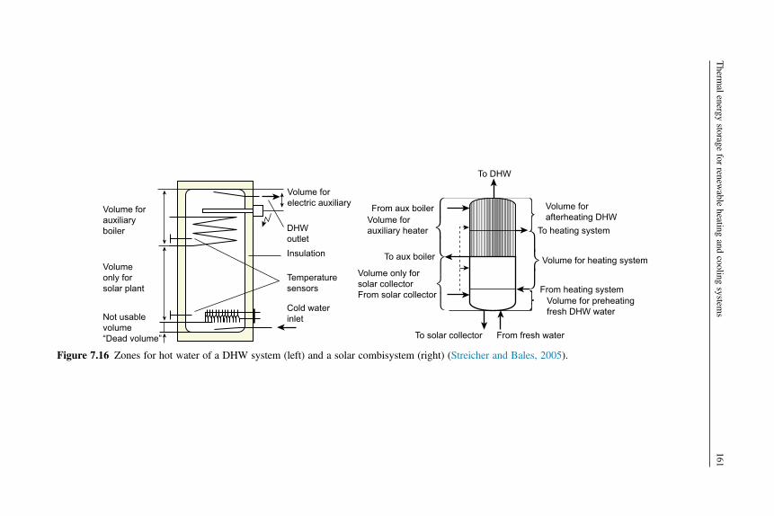
The other big application of water storage systems is the combisystem, in whichDHW and heating are produced. Streicher and Bales (2005) stated that one of thekey elements of a solar heating system is the hot water store, which has to fulfill severaltasks:
• Deliver sufficient energy to the heat sink• Decouple mass flows of heat sources and heat sinks• Store heat from unsteady heat sources (solar) from times when excess heat is available to
times when too little or no heat is available (either short-term storage from day to night orover one to a few days, or seasonal storage)
• Extend the running times for auxiliary heating devices to increase their efficiency and lowerstartup/shutdown emissions
• Allow a reduction in heating capacity of auxiliary heating devices• Store the heat at the appropriate temperature levels without mixing (stratification) to avoid
energy losses
The design of the water store in a combisystem greatly affects the overall systemperformance. The principle of a water store connected to a solar system and withauxiliary heat input is shown in Figure 7.16. In these systems, the stratificationof the hot water is of great importance, and charging and discharging must bedone carefully considering this fact. This is why water tanks use stratifying units(Figure 7.17).
7.2.2.2 PCM in HVAC systems
The use of night cooling ventilation in addition to PCM is a very powerful strategy forreducing the cooling demand of buildings. Nevertheless, there are inherent drawbacksin the way things have been done so far:
• The limited area of contact between PCM and the air• The very low convective heat transfer coefficient, which prevents the use of significant
amount of PCM• The very low utilization factor of the cool stored due to the large phase shift between the time
when cool is stored and when it is required by the building
A very powerful well-known strategy for reducing the cooling demand of buildingsis the use of low outdoor air temperatures during the night to cool the structures of thebuilding. In many cases, the nighttime outdoor air climatic conditions of many Med-iterranean locations allow a significant compensation of the daytime solar and internalheat gains (Allard et al., 1998).
The performance of a night cooling application depends on (Alvarez et al., 1997):
• The climate, which provides the availability of the heat sink in terms of its thermal level andits variability throughout the year and on a daily basis.
• The cooling needs of the building (absolute values and load profiles). The combination of 1and 2 gives the extent to which the requirements can be covered by the cooling technique.
160 Renewable Heating and Cooling
Volume forelectric auxiliary From aux boiler
To aux boiler
Volume forauxiliary heater
Volume only forsolar collectorFrom solar collector
To solar collector From fresh water
To DHW
From heating systemVolume for preheatingfresh DHW water
Volume for heating system
Volume forafterheating DHW
To heating systemDHWoutlet
Temperaturesensors
Insulation
Cold waterinlet
Volume forauxiliaryboiler
Volumeonly forsolar plant
Not usablevolume“Dead volume”
Figure 7.16 Zones for hot water of a DHW system (left) and a solar combisystem (right) (Streicher and Bales, 2005).
Therm
alenergy
storagefor
renewable
heatingand
coolingsystem
s161

The efficiency of the technology used to transfer heat from the heat sink (nighttimeoutdoor air) to the building.
The efficiency of a night-cooling strategy lies in the ability of the building inertia tostore cool during the night and to use it during the next day. The role of inertia appearsthen double-linked to this strategy. It can be characterized by means of the storageefficiency and the utilization factor (Allard et al., 1998; Alvarez et al., 1997).
There are several alternatives to incorporate PCM in buildings. Tyagi and Buddhi(2007) present a classification consisting of three types:
• PCMs in building walls• PCMs in other building components (for example, subfloor or ceiling systems)• PCMs in separate heat- or cold-storage systems
Athienities and Chen (2000) showed the possibility of using PCMs in underfloorheating systems. The idea is the use of a radiant heating system but with increased per-formance due to the inclusion of PCMs. The costs have been shown to be reduced ifthe PCM is used with electrically heated underfloor systems due to the reduction ofpeak loads and to the use of cheaper night electricity. Similarly, Nagano et al.(2000) presented a floor air-conditioning system with latent heat storage in buildings.Floor size of the experimental cell was 0.5 m2. Granulated PCM was made of foamed-waste glass beads and a mixture of paraffin. The PCM-packed bed of 3 cm thicknesswas installed under the floorboard with multiple small holes. The change in room tem-perature and the amount of stored heat were measured, and results showed the possi-bilities of cooling load shifting by using packed granulated PCMs.
These new solutions use PCMs in containers, which are located inside an air cham-ber, in which air is moved by fans with variable flow (forced convection). This air flowis controlled by a control system that can change the air-flow rate, the origin, and thedestination of air flow. They even can totally stop the system. The PCM containers aresealed, made of a material that does not react with the PCM contained, and stimulateheat exchange with air around them. In principle, three basic forms have been consid-ered: fins, cylinders, and spheres.
In addition, ceiling boards can incorporate PCM for heating and cooling of build-ings. An example is that developed by Kodo and Ibamoto (2002), in which PCMs areused for peak-shaving control of air-conditioning systems in an office building
Aux.heatedzone
Solarheatedzone
Solar Solar
Solar inlet
Spaceheatreturn
DHW
DHWcooledzone
Figure 7.17 Four different stratifying devices for solar water tanks (Streicher and Bales, 2005).
162 Renewable Heating and Cooling

(Figure 7.18). The authors claim that these systems have some advantages over con-ventional building thermal storage systems that use concrete floor slabs:
1. More efficient thermal storage is expected, because high-density cool air pools on the PCMceiling board that forms the floor of the ceiling space.
2. All of the ceiling board can be used for thermal storage, because the cool air can flow throughthe ceiling chamber without being interrupted by beams.
3. Because the surface temperature of the ceiling board is kept at the PCM melting point for anextended period, the indoor thermal environment, including the radiant field, can beimproved.
Ceiling boards incorporated with PCMs for air-conditioning systems play an effec-tive role on the peak-shaving control. Saman and Belusko (1997) developed a roof-integrated solar air-heating storage system. The latent heat storage unit, in which anexisting corrugated iron roof sheet is used as solar collector, is to store heat duringthe day and supply the heat at night or when sunshine is unavailable. Besides exper-imental analysis, many numerical works were also carried out on the thermal perfor-mance analyses of this system (Vailaltojjar and Saman, 2001; Saman et al., 2005).
Koschenz and Lehmann (2004) put forward a new concept of thermally activatedceiling panel for refurbished buildings. In this system, the mixture of microencapsu-lated PCM and gypsum was poured into a sheet-steel tray, which was used as a supportfor maintaining the mechanical stability of the panels. A capillary water tube systemwas applied to control the thermal mass. They tested the thermal performance ofthis system and indicated that only a 5 cm layer of microencapsulated PCM and gyp-sum was enough for a standard office to keep within comfortable temperatures.
Ceiling chamber
PCM ceiling board
Chilled water coil
AHU
Chilled airsupply
Ceiling chamber
Outlet for normalcooling time
PCM ceiling board
Return airChilled air
supply
AHU
PCM ceiling board
Outlet for peakshaving time
Pre-cooled air
Ceiling chamber Chilled by PCM ceiling board Chilled airsupply
AHU
(a) (b)
(c)
Figure 7.18 Ceiling board with PCM for cooling peak shaving: (a) overnight thermal storagetime; (b) normal cooling time; (c) peak-shaving control time (Kodo and Ibamoto, 2002).
Thermal energy storage for renewable heating and cooling systems 163

A new type of ventilated façade with macroencapsulated PCM in its air cavitywas developed by de Gracia et al. (2013a). The thermal performance of this specialbuilding envelope was experimentally tested to analyze its potential in reducingthe cooling demand during the summer season (de Gracia et al., 2013a) and thewinter season (de Gracia et al., in press) in the Continental Mediterranean climate,and it was numerically extrapolated to different performance scenarios (de Graciaet al., 2013b). Two identical house-like cubicles located in Puigverd de Lleida(Spain) were monitored during summer 2012, and in one of them, a ventilatedfaçade with PCM was located in the south wall (Figure 7.19). Six automatizedgates were installed at the different openings of the channel to control the opera-tional mode of the façade. This versatility allows the system to be used as a coldstorage unit, as an overheating protection system, or as a night free-cooling appli-cation. The experimental results demonstrated the high potential of the night free-cooling effect in reducing the cooling loads of a building. This operation modecould inject air at a temperature below the set point under both severe and mildsummer conditions (34.9 MJ day�1 and 42.8 MJ day�1, respectively). The systemcan successfully prevent the overheating effect between the PCM solidification andmelting periods, because the air inside the cavity was even lower than the outerenvironmental temperature during the peak load. The thermal performance ofthis system is very sensitive to the weather conditions and the cooling demandof the final users.
7.2.2.3 Sorption systems
Only a few applications using liquid absorption can be found. Ruiter (1987) presentedan absortion TES cycle using H2O/NH3. An experimental setup was built with a netheat output of 5 kW and a storage capacity of 40 kWh. The energy density reachedwas 111.1 kWh kg�1, based on the total mass of absorbate and weak solution.
Figure 7.19 Experimental setup to test a ventilated façade with macroencapsulated PCMs in itsair cavity located in Spain (de Gracia et al., 2013a).
164 Renewable Heating and Cooling

The pair NaOH/H2O was studied by Weber and Dorer (2008) using a single-stageclosed absorption prototype for long-term heat storage. The prototype built has threestorage tanks for water, strong solution, and weak solution (Figure 7.20).
Based on a three-phase absorption cycle, ClimateWell (Jonsson et al., 2000; Bolin,2005; Olsson and Bolin, 2007) developed a system combining short-term absorptionthermal storage and solar cooling technologies. The tests carried out showed that witha 35 kWh heat input, a cooling storage capacity of 22 kWh could be obtained. Thecalculated energy density for LiCl was 253 kWh m3, giving a final energy density1.2 times that of water.
Quinnell et al. (2011) and Quinnell and Davidson (2012) presented a concept usinga single storage vessel for storing liquid calcium chloride in a closed liquid absorptionsystem. The storage tank in this prototype is designed to provide higher energy densityand to decrease thermal losses during the storage process (Figure 7.21).
A demonstrative LiBr/H2O prototype with a heat storage capacity of 8 kWh and adischarge rate of 1 kW has recently been developed by N’Tsoukpoe et al. (2013)(Figure 7.22). The prototype is based on a long-term absorption storage cycle andhas two storage tanks and a reactor with two vertical falling-film heat exchangers.The achieved charging power was 2e5 kW and the heat storage up to 13 kWh. Asin previous prototypes, crystallization of the salts was the main problem found.
Figure 7.20 Double-stage NaOH/H2O prototype built at the Swiss Federal Laboratories forMaterials Science and Technology (EMPA) (Weber and Dorer, 2008).
Thermal energy storage for renewable heating and cooling systems 165

Heat exchanger
Densityinterface
From solar collector
H2O
DilutedCaCl2(aq)
ConcentratedCaCl2(aq)
ConcentratedCaCl2 solution
Storage tank
Water Heat pump
Solar collector
Diluted CaCl2solution
Load
(a) (b) (c)
Figure 7.21 Closed CaCl2/H2O absorption heating system with a single-store vessel: (a) system schematic (Quinnell and Davidson, 2012);(b) storage tank schematic (Quinnell et al., 2011); (c) anticipated convective flow patterns during sensible charging (Quinnell et al., 2011).
166Renew
ableHeating
andCooling

The prototype MODESTORE used the positive points of the pair silica gel/H2O,such as being environmentally harmless and relatively cheap and having low desorp-tion temperatures (Figure 7.23). This prototype used a spiral heat exchanger containing200 kg of silica gel (Jaenig et al., 2006). The storage capacity obtained in the labora-tory was 13 kW. The authors concluded that silica gel is not suitable for long-termsorption TES.
Lu et al. (2003) used a closed-adsorption cold-storage system with the working pairzeolite 13X/water. This prototype has one adsorber and a cold-storage tank (Figure 7.24).The average cooling power reported is 4.1 kW, and the total experimental capacity of thecold storage 5.5 kWh when the temperature of adsorption bed reached its maximumvalue of 125 �C.
Boer et al. (2004) developed the SWEAT prototype of a modular chemical adsorp-tion cooling system using the working pair Na2S/H2O (Figure 7.25). The module has ashell and tube design, a condenser, and an evaporator coil. The test results showed thata cold storage capacity of 2.1 kWh and a cooling COP of 0.56 were achieved with aheat input of 3.7 kWh.
Mauran et al. (2008) presented a storage prototype using the reversible chemicalreaction between SrBr2 and SrBr2$H2O. The reactor integrated an evaporator/condenserfor the solidegas reaction. The heating and cooling power obtained proved that the mostchallenging feature that needs to be overcome in this type of concept is the heat transferproblem encountered.
A solar air-conditioning pilot plant with a daily cooling capacity of 20 kWh with aworking pair of BaCl2/NH2 was presented by Stitou et al. (2011) (Figure 7.26). Theheat input is at 60 to 70 �C from 20 m2 of flat-plate solar collectors. Along with
Reactor Solution tank
Pressure sensor
Water storage
tank
External circuits of the heat exchangers
Liquid level meter
Volumetric flow meters
Mass flow meters
Solution pump
Figure 7.22 LiBr/H2O absorption prototype developed by N’Tsoukpoe et al. (2013).
Thermal energy storage for renewable heating and cooling systems 167

Mauran et al. (2008), this prototype includes expanded graphite in the design toimprove the heat transfer. The prototype also includes a hot PCM tank to store theexcess solar heat and a cold PCM tank to supply cooling when the sorption reactionis not available. Experiments during 2 years showed an average yearly efficiency ofsolar collectors of 0.4 to 0.5 and COP of 0.3 to 0.4. The daily storage capacity wasabout 0.8e1.2 kWh m�2 plate solar collector at 4 �C.
The ZAE Bayern installed a large-scale open-adsorption TES using zeolite13X/water to heat a school building in winter and to cool a jazz club in summer inMunich (Hauer, 2002, 2007). Figure 7.27 shows the heat flux during charging anddischarging. The prototype obtained storage densities of 124 kWh m�3 for heatingand 100 kWh m�3 for cooling with a COP of 0.9 and 0.86, respectively.
Another design is that named chemical heat transferelow temperature (CWT-NT)(Kerkes et al., 2011; Kerskes et al., 2012; Metter et al., 2013). This concept consists ofa long-term thermochemical energy storage integrated in a solar thermal combisystemfor a composite of zeolite and salt (Figure 7.28). The system is designed as an opensystem using ambient air for charging and discharging.
Space heating flow
Silica gel area
Silica gel area
Heat exchanger
Evaporator/condenser
Evaporation/condensation area
Flow evaporation/condensation heat exchanger
Return evaporation/condensationheat exchanger
Space heating flowSpace heating return
Space heatingreturn
Figure 7.23 MODESTORE prototype (Jaenig et al., 2006).
168 Renewable Heating and Cooling

Air
Adsorber
Exhausted gas
Damper
Condenser
Reservoir
Valve
Fan coil
Pump
Driver’s
cab
Evaporator
Figure 7.24 Zeolite/water adsorption cold storage system (Lu et al., 2003).
Figure 7.25 SWEAT storage concept (Boer et al., 2004).
Thermal energy storage for renewable heating and cooling systems 169

Figure 7.26 Solar sorption pilot plant for air conditioning (Stitou et al., 2011).
SteamSteamCondensateCondensate
Charging (night)
TCS130 °C
40 °C
Zeolite
35 °CHeatexchanger
Fan
25 °C
BuildingDistrictheat
Discharging (day)
TCS100 °C
25 °C
Zeolite
65 °CHeatexchanger
Fan
30 °C
Building
Humidifier
Districtheat
(a) (b)
Figure 7.27 Open adsorption TES system connected to the district heating system in Munich(Hauer, 2002).
170 Renewable Heating and Cooling

7.2.3 Seasonal storage
7.2.3.1 Underground thermal energy storage
Underground thermal energy storage (UTES) with both boreholes (BTES) and aqui-fers (ATES) are the most developed storage concepts and are mostly used for seasonalstorage. The description of the concepts can be found in Paksoy (2007) and Mehlingand Cabeza (2008).
Heat storage in ATES consists in extracting groundwater from a well, heating thiswater with an available heat source, and then reinjecting it back into the aquifer inanother well. The estimated heat storage capacity of 105 m3 of aquifer is 3 MJ foreach 10 K temperature range (Hasnain, 1998).
7.2.3.2 Water pits and solar ponds
Novo et al. (2010) reviewed TES systems in large basins (water tanks and gravelewater pits). These authors claimed that the energy costs can be reduced with increasingstorage volume in large-scale solar applications.
The most common use of water tanks in Europe is in connection with solar collec-tors for production of warm water for space heating and/or DHW. The main applica-tion is in smaller solar plants such as described above, but there are some examples oflarge water tanks being used for seasonal storage and also used as a buffer storage inconnection with large-scale solar heating systems.
Backupheater Combistore
Collector array
WW
CW
Space heating
Material-flux
Reactor
Storage materialreservoir
Exhaust air
Supply air
Thermo chemical energy store
Air/airheat exchanger
Air/waterheat exchanger
Anhydrate
Hydrate
Figure 7.28 CWT-NT concept schematics (Kerskes et al., 2012).
Thermal energy storage for renewable heating and cooling systems 171

These large water tanks usually consist of a reinforced concrete tank partiallyburied in the ground. It is thermally insulated at least in the roof area and on the ver-tical walls. Usually steel liners are introduced in the structure to guarantee watertightness and to reduce heat losses caused by vapor transport through the walls(Schmidt et al., 2004). Such a system was installed in Germany (Figure 7.29)together with other concepts.
Storage pits are usually filled with water, but sometimes also rock is added in the pit.Pits are normally buried in the ground and need to be waterproofed and insulated at leastat the side walls and on the top. The watertight plastic liner is filled with a gravelewatermixture that constitutes the storage material. Heat is charged into and discharged out ofthe store either by direct water exchange or by plastic piping installed in different layersinside the store. No other bearing structure is necessary apart from the cover (lid)that could be used for other purposes. The gravelewater mixture has lower specificheat capacity than water alone; for this reason, the volume of the whole basin hasto be approximately 50% higher compared to hot-water heat storage to obtain thesame heat storage capacity.
Solar ponds are large volumes of saline solution with higher concentration of saltsat the bottom than at the top (Figure 7.30). Solar ponds are an economical method tocollect and store solar thermal energy in the temperature range 50e95 �C (Novo et al.,2010).
Solar c
ollect
ors
Solar c
ollect
ors
District heating netSolar net
Hot water heat store
(seasonal heat store)
Heat
transfer
substation
Heat
transfer
substation
Heating central
Gas
burner
Hot
tap
water
Hot
tap
water
Freshwater
cccc
Freshwater
Figure 7.29 Scheme of the system installed in Friedrichshafen, Germany (Schmidt et al., 2004).
172 Renewable Heating and Cooling

Novo et al. (2010) presented a comparison of these storage systems, stating that thegravelewater pit technology can reduce construction costs and the upper part ofthe store can be used as part of the residential area but needs more volume to storethe same thermal energy than a water tank design. The demonstration sites carriedout showed that solar collector efficiency and heat losses from the storage tank andthe piping network are most important.
7.2.3.3 Thermochemical storage
Most of the concepts presented in Section 7.2.2.2 as sorption systems are being furtherdeveloped today for seasonal storage.
7.3 R&D needs and future trends in technologicaldevelopment, markets, and applications
The R&D needs have been captured by the European Technology Platform on Renew-able Heating and Cooling (RHC Platform—www.rhc-platform.org) Strategic ResearchPriorities (Axel et al., 2012). The RHC Platform claims that the emphasis of scientificresearch, development, and demonstration activities must be focused toward storagetechnologies that enhance the performance of energy systems and facilitate the integra-tion of renewable energy systems in buildings. Table 7.6 presents the strategic andresearch priorities for TES according to the RHC Platform.
Because many technologies exist at laboratory scale, the future of TES applica-tions depends on the reduction of costs and improving the ability to efficiently shiftenergy demand over days, weeks, or seasons. To achieve these objectives, effortsshould be focused on advanced sensible heat storage, PCMs, sorption, and thermo-chemical methods. The most promising areas of research are in latent heat storageand novel thermochemical concepts. Decentralized systems and stores connectedto the district heating and cooling networks have potential, so both must beconsidered.
UCZ
NCZ
LCZ
Figure 7.30 Schematic of a solar pond (UCZ ¼ upper convective zone; NCZ ¼ nonconvectivezone; LCZ ¼ lower convective zone) (Tatsikjoudoung et al., 2013).
Thermal energy storage for renewable heating and cooling systems 173

Table 7.6 Strategic and research priorities for TES according to the RHC platform (Axel et al., 2012)
Basic research Applied R&D Demonstration
Sensible TES • Materials research for thereduction of heat losses
• Materials research for high-temperature storage withhigh thermal conductivity
• Fluids combining heattransfer and heat storage
• Microbiology in undergroundthermal energy storage (UTES)systems
• Flexible volume tank systems• Development of new methods ofTES materials’ analysis
• Optimization of hydraulics inadvanced water stores, reductionof mixing, and increasedstratification
• Control strategies for integratingsensible stores into the smart grid
• High-temperature undergroundstorage (HT-UTES)
Latent TES • Optimization of phasechange heat storage
• Fluids combining heattransfer and heat storage
• Integration of phase change materialsin building elements
• Software algorithms and codesfor ERBP enabling softwarepackages
Thermochemicalstorage
• Materials for thermochem-ical heat storage
• Fluids combining heattransfer and heat storage
• Optimization of thermochemical heatstorage processes
• High-temperature thermochemicalsystems
Research prioritiesat system level
• Materials for storagecontainment
• Advanced sensoring in storagesystems
• Distributed thermal energy storagefor smart electricity grids in smartcities
• Optimized integration of UTESsystems
• Advanced control strategies• Storage of rejection heat in solarcooling processed and solarpower plants
• System evaluation
Nontechnological priorities • Education and training• Knowledge of system performance• Labeling or certification of TES devices• Legal framework UTES (ATES/BTES)• Public awareness
174Renew
ableHeating
andCooling

Another topic is the improvement of the properties of TES materials, especially inimproving the lifetime chemical and physical stability. The durability of new systemsand their parts also needs to be assessed to ensure their long-term performance.
According to Mahlia et al. (2014), there are three key barriers for the deployment ofthe energy storage technology, regulations, and utility processes that disfavor energystorage, costs, and lack of awareness of energy storage benefits. These three barrierscan also be applied to TES. Important is the fact that there is no experience in deploy-ing energy storage at large scale, so policymakers lack conclusive data about the costsand energy savings capacity of TES.
Sources of further information and advice
Further information on the topic can be found in the published books such as Dincerand Rosen (2002), Hadorn (2005), Paksoy (2007), Mehling and Cabeza (2008), and achapter in Cabeza (2012).
Many reviews have been published on the topic: Zalba et al. (2003), Farid et al. (2004),Kenisarin and Mahkamov (2007). Sharma et al. (2009), Gil et al. (2010), Cabeza et al.(2011), Cot-Gores et al. (2012), Rathod and Banerjee (2013), and Soares et al. (2013).
Important is the work developed within the International Energy Agency Imple-menting Agreements. Worth mentioning are Energy Conservation through EnergyStorage IA (ECES IA—www.iea-eces.org) and the Solar Heating and Cooling IA(SHC Program—www.iea-shc.org).
References
Ahmad, M., Bontemps, A., Sallée, H., Quenard, D., 2006. Thermal testing and numericalsimulation of a prototype cell using light wallboards coupling vacuum isolation panels andphase change material. Energ. Buildings 38, 673e681.
Allard, F., Santamouris, M., �Alvarez, S., Guarraccino, G., Maldonado, E., 1998. NaturalVentilation in Buildings: A Design Handbook. Earthscan/James & James, Berlin.
Alvarez, S., Maestre, I., Velazquez, R., 1997. Design methodology and cooling potential of theenvironmental heat sinks. Int. J. Sol. Energ. 19 (1e3), 179e197.
Athienitis, A.K., Liu, C., Hawes, D., Banu, D., Feldman, D., 1997. Investigation of the thermalperformance of a passive solar test-room with wall latent heat storage. Build. Environ. 2 (5),3405e3410.
Athienities, A., Chen, Y., 2000. The effect of solar radiation on dynamic thermal performance offloor heating systems. Sol. Energ. 69 (3), 229e237.
Axell, M., Bakker, M., Brunialti, A., Cabeza, L.F., Calia, E., Corberan, J.M., de Boer, R.,Fevrier, N., Freni, A., Froning, S., Griffiths, P., Hadorn, J.C., Jakob, U., Landolina, S.,Lunqvist, P., Monsberer, M., Nordman, R., Nowak, T., Oltersdorf, T., Papillon, P., Py, X.,Sanner, B., Schossig, P., Sparber, W., Spoelstra, S., Trigg, L., van Aarssen, M., vanBael, J., van Helden, W., Werner, S., Weiss, W., Ziegler, F., 2012. Strategic researchpriorities for renewable heating & cooling cross-cutting technology. In: European Tech-nology Platform on Renewable Heating and Cooling.
Thermal energy storage for renewable heating and cooling systems 175
Barreneche, C., de Gracia, A., Serrano, S., Navarro, M.E., Borreguero, A.M., Fern�andez, A.I.,Carmona, M., Rodríguez, J.F., Cabeza, L.F., 2013. Comparison of three different devicesavailable in Spain to test thermal properties of building materials including phase changematerials. Appl. Energ. 109, 421e427.
Boer, R.D., Haije, W.G., Veldhuis, J.B.J., Smeding, S.F., 2004. Solid-sorption cooling withintegrated thermal storage: the SWEAT prototype. In: Proceedings of HPC 2004-3rdInternational Heat Powered Cycles Conference, Larnaca, Cyprus.
Bolin, G., 2005. Chemical Heat PumpWorking According to the Hybrid Principle. Internationalpatent publication no. WO 2005/054757 A1.
Cabeza, L.F., 2005. Storage techniques with phase change materials. In: Hadorn, J.C. (Ed.),Thermal Energy Storage for Solar and Low Energy Buildings. Universitat de Lleida, Spain,pp. 77e105.
Cabeza, L.F., Ib�a~nez, M., Solé, C., Roca, J., Nogués, M., 2006. Experimentation with a watertank including a PCM module. Sol. Energ. Mat. Sol. C. 90, 1273e1282.
Cabeza, L.F., Castell�on, C., Nogués, M., Medrano, M., Leppers, R., Zubillaga, O., 2007. Use ofmicroencapsulated PCM in concrete walls for energy savings. Energ. Buildings 39 (2),113e119.
Cabeza, L.F., Castell, A., Barreneche, C., de Gracia, A., Fern�andez, A.I., 2011. Materials used asPCM in thermal energy storage in buildings: a review. Renew. Sust. Energ. Rev. 15,1675e1695.
Cabeza, L.F., 2012. Thermal energy storage. In: Sayigh, A. (Ed.), Comprehensive RenewableEnergy, vol. 3. Elsevier, Oxford, pp. 211e253.
Castell, A., Martorell, I., Medrano, M., Pérez, G., Cabeza, L.F., 2010. Experimental study ofusing PCM in brick constructive solutions for passive cooling. Energ. Buildings 42,534e540.
Castell�on, C., Castell, A., Medrano, M., Martorell, I., Cabeza, L.F., 2009. Experimental study ofPCM inclusion in different building envelopes. J. Solar Energy Eng, Trans ASME 131 (4),0410061e0410066.
Cot-Gorés, J., Castell, A., Cabeza, L.F., 2012. Thermochemical energy storage and conversion:a-state-of-the-art review of the experimental research under practical conditions. Renew.Sust. Energ. Rev. 16, 5207e5224.
Dincer, I., Rosen, M.A., 2002. Thermal energy storage (TES) methods. In: Dincer, I.,Rosen, M.A. (Eds.), Thermal Energy Storage: Systems and Applications. John Wiley &Sons, New York, NY, pp. 93e212.
Farid, M.M., Khudhair, A.M., Razack, S.A.K., Al-Hallaj, S., 2004. A review on phase changeenergy storage: materials and applications. Energ. Convers. Manage. 45, 1597e1615.
de Gracia, A., Navarro, L., Castell, A., Ruiz-Pardo, �A., �Alvarez, S., Cabeza, L.F., 2013a.Thermal analysis of a ventilated facade with PCM for cooling applications. Energ.Buildings 65, 508e515.
de Gracia, A., Navarro, L., Castell, A., Cabeza, L.F., 2013b. Numerical study on the thermalperformance of a ventilated facade with PCM. Appl. Therm. Eng. 61 (2), 372e380.
de Gracia, A., Navarro, L., Castell, A., Ruiz-Pardo, A., Alv�arez, S., Cabeza, L.F., 2013.Experimental study of a ventilated facade with during winter period. Energ. Buildings 58,324e332.
Gil, A., Medrano, M., Martorell, I., et al., 2010. State of the art on high temperature thermalenergy storage for power generation. Part 1—concepts, materials and modellization.Renew. Sust. Energ. Rev. 14, 31e55.
Hadorn, J.C. (Ed.), 2005. Thermal Energy Storage for Solar and Low Energy Buildings. Universitatde Lleida, Spain, pp. 77e105.
176 Renewable Heating and Cooling
Hasnain, S.M., 1998. Review on sustainable thermal energy storage technologies, Part I: heatstorage materials and techniques. Energ. Convers. Manage. 39, 1127e1138.
Hauer, A., 2002. Thermal energy storage with zeolite for heating and cooling applications.In: Proceedings of ISHPC 2002-International Sorption Heat Pump Conference.Shanghai, China.
Hauer, A., 2007. Sorption theory for thermal energy storage. In: Paksoy, H.O. (Ed.), ThermalEnergy Storage for Sustainable Energy Consumption: Fundamentals, Case Studies andDesign, NATO Sciences Series, II. Mathematics, Physics and Chemistry, vol. 234.Springer, Dordrecht, pp. 393e408.
Jaehnig, D., Hausner, R., Wagner, W., Isaksson, C., 2006. Thermo-chemical storage for solarspace heating in single-family house. In: Proceedings of 10th International Conference onThermal Energy Storage, New Jersey, USA.
Jonsson, S., Solsson, R., Kaarebing-Olsson, M., 2000. A Chemical Heat Pump. Internationalpatent publication no. WO 00/37864 A1.
Kato, Y., 2007. Chemical energy conversion technologies for efficient energy use. In: Paksoy, H.O.(Ed.), Thermal Energy Storage for Sustainable Energy Consumption: Fundamentals, CaseStudies and Design, NATO Sciences Series, II. Mathematics, Physics and Chemistry, vol. 234.Springer, Dordrecht, pp. 377e391.
Kenisarin, M., Mahkamov, K., 2007. Solar energy storage using phase change materials. Renew.Sust. Energ. Rev. 11, 1913e1965.
Kerskes, H., Mette, B., Bertsch, F., Asenbeck, S., Dr€uck, H., 2011. Development of a thermo-chemical energy storage for solar thermal applications. In: Proceedings of ISES SolarWorld Congress 2011. Kassel, Germany.
Kerskes, H., Mette, B., Bertsch, F., Asenbeck, S., Dr€uck, H., 2012. Chemical energy storageusing reversible solid/gas-reactions (CWS)-results of the research project. Energy Procedia.30, 294e304.
Kodo, T., Ibamoto, T., October 1e2, 2002. Research on using the PCM for ceiling board. In:IEA ECES IA, Annex 17, 3rd workshop, Tokyo, Japan.
Koschenz, M., Lehmann, B., 2004. Development of a thermally activated ceiling panel with PCMfor application in lightweight and retrofitted buildings. Energ. Buildings 36, 567e578.
Kousksou, T., Bruel, P., Cherreau, G., Leoussoff, V., El Rhafiki, T., 2011. PCM storage for solarDHW: from an unfulfilled promise to a real benefit. Sol. Energy 85, 2033e2040.
Kuznik, F., Virgone, J., Noel, J., 2008a. Optimization of a phase change material wallboard forbuilding use. Appl. Therm. Eng. 28, 1291e1298.
Kuznik, F., Virgone, J., Roux, J.J., 2008b. Energetic efficiency of room wall containing PCMwallboard: a full-scale experimental investigation. Energ. Buildings 40, 148e156.
Kuznik, F., Virgone, J., 2009. Experimental investigation of wallboard containing phase changematerial: data for validation of numerical modelling. Energ. Buildings 41, 561e570.
Kuznik, F., Virgone, J., Johannes, K., 2011. In-situ study of thermal comfort enhancement in arenovated building equipped with phase change material wallboard. Renew. Energ 36,1458e1462.
Lv, S.L., Zhu, N., Feng, G.H., 2006. Impact of phase change wall room on indoor thermalenvironment in winter. Energ. Buildings 38, 18e24.
Lu, Y.Z., Wang, R.Z., Zhang, M., Jiangzhou, S., 2003. Adsorption cold storage system withzeolite-water working pair used for locomotive air conditioning. Energ. Convers. Manage.44, 1733e1743.
Mahlia, T.M.I., Saktisahdan, T.J., Jannifar, A., Hasan, M.H., Matseelar, H.S.C., 2014. A reviewof available methods and development on energy storage; technology update. Renew. Sust.Energ. Rev. 33, 532e545.
Thermal energy storage for renewable heating and cooling systems 177

Mandilaras, I., Stamatiadou, M., Katsourinis, D., Zannis, G., Founti, M., 2013. Experimentalthermal characterization of a Mediterranean residential building with PCM gypsum boardwalls. Build. Environ. 61, 93e103.
Mauran, S., Lahmidi, H., Goetz, V., 2008. Solar heating and cooling by a thermochemicalprocess first experiments of a prototype storing 60 kWh by a solid/gas reaction. Sol. Energ.82, 623e636.
Mehling, H., Cabeza, L.F., 2008. Heat and Cold Storage with PCM: An Up to Date Introductioninto Basics and Applications. Springer, Heidelberg, Berlin.
Mette, B., Kerskes, H., Dr€uck, H., M€uller-Steinhagen, H., 2013. New highly efficient regen-eration process for thermochemical energy storage. Appl. Energ. 109, 352e359.
Nagano, K., Mochida, T., Iwata, K., Hiroyoshi, H., Domanski, R., Rebow, M., 2000.Development of new PCM for TES of the cooling system, Terrastock. In: Benner, M.,Hahne, E.W.P. (Eds.), 8th International Conference on Thermal Energy Storage,pp. 345e350.
Neeper, D.A., 2000. Thermal dynamics of wallboard with latent heat storage. Sol. Energ. 68 (5),393e403.
Novo, A.V., Bayon, J.R., Castro-Fresno, D., Rodriguez-Hernandez, J., 2010. Review of sea-sonal heat storage in large basins: water tanks and gravel-water pits. Appl. Energ. 87,390e397.
N’Tsoukpoe, K.E., Le Pierr�es, N., Luo, L., 2013. Experimentation of a LiBr-H2O absorptionprocess for long-term solar thermal storage: prototype design and first results. Energy 53,179e198.
Olsson, R., Bolin, G., 2007. Chemical Heat Pump Working According to the Hybrid Principle.International patent publication no. WO 2007/139476 A1.
Paksoy, H.O., 2007. In: Thermal Energy Storage for Sustainable Energy Consumption: Fun-damentals, Case Studies and Design. NATO Sciences Series, II. Mathematics, Physics andChemistry, vol. 234. Springer, Dordrecht, pp. 393e408.
Pasupathy, A., Velraj, R., 2008. Effect of double layer phase change material in building roof foryear round thermal management. Energ. Buildings 40, 193e203.
Quinnell, J.A., Davidson, J.H., 2012. Mass transfer during sensible charging of a hybridabsorption/sensible storage tank. Energy Procedia. 30, 353e361.
Quinnell, J.A., Davidson, J.H., Burch, J., 2011. Liquid calcium chloride solar storage: conceptand analysis. J. Sol. Energy. Eng. 133, 011010e011011-8.
Rathod, M.K., Banerjee, J., 2013. Thermal stability of phase change materials used in latent heatenergy storage systems: a review. Renew. Sust. Energ. Rev. 18, 246e258.
Ruiter, J.P., 1987. Storage of Thermal Enregy by Means of an Absorption Cycle (Ph.D. thesis).Delft University of Technology, Delft.
Saman, W.Y., Belusko, M., 1997. Roof integrated unglazed transpired solar air heater. In:Lee, T. (Ed.), Proceedings of the 1997 Australian and New Zealand Solar Energy Society.Paper 66, Canberra, Australia.
Saman, W., Bruno, F., Halawa, E., 2005. Thermal performance of PCM thermal storage unit fora roof integrated solar heating system. Sol. Energ. 78, 341e349.
Schmidt, T., Mangold, D., M€uller-Steinhagen, H., 2004. Central solar heating plants withseasonal storage in Germany. Sol. Energ. 76, 165e174.
Schossig, P., Henning, H.-M., Gschwander, S., Haussmann, T., 2005. Micro-encapsulatedphase-change materials integrated into construction materials. Sol. Energ. Mat. Sol. C. 89,297e306.
Sharma, A., Tyagi, V.V., Chen, C.R., Buddhi, D., 2009. Review on thermal energy storage withphase change materials and applications. Renew. Sust. Energ. Rev. 13, 318e345.
178 Renewable Heating and Cooling

Soares, N., Costa, J.J., Gaspar, A.R., Santos, P., 2013. Review of passive PCM latent thermalenergy storage systems towards buildings’ energy efficiency. Energ. Buildings 59,82e103.
Stitou, D., Mazet, N., Mauran, S., 2011. Experimental investigation of a solid/gas thermo-chemical storage process for solar air-conditioning. Energy 41, 261.
Streicher, W., Bales, C., 2005. Combistores. In: Hadorn, J.C. (Ed.), Thermal Energy Storage forSolar and Low Energy Buildings. Universitat de Lleida, Spain, pp. 77e105.
Talmatsky, E., Kribus, A., 2008. PCM storage for solar DHW: an unfulfilled promise? Sol.Energ. 82, 861e869.
Tatsidjodoung, P., Le Pierr�es, N., Luo, L., 2013. A review of potential materials for thermalenergy storage in building applications. Renew. Sust. Energ. Rev. 18, 327e349.
Tyagi, V.V., Buddhi, D., August 2007. PCM thermal storage in buildings: a state of art. Renew.Sust. Energ. Rev. 11 (6), 1146e1166.
Vakilaltojjar, S.M., Saman, W., 2001. Analysis and modeling of a phase change storage systemfor air conditioning applications. Appl. Therm. Eng. 21, 249e263.
Weber, R., Dorer, V., 2008. Long-term heat storage with NaOH. Vacuum 82, 708e716.Xu, X., Zhang, Y.P., Lin, K.P., Di, H.F., Yang, R., 2005. Modeling and simulation on the
thermal performance of shape-stabilized phase change material floor used in passive solarbuildings. Energ. Buildings 37, 1084e1091.
Yu, N., Wang, R.Z., Wang, L.W., 2013. Sorption thermal storage for solar energy. Prog. Energ.Combust. 39, 489e514.
Zalba, B., Marín, J.M., Cabeza, L.F., Mehling, H., 2003. Review on thermal energy storage withphase change: materials, heat transfer analysis and applications. Appl. Therm. Eng. 23,251e283.
Thermal energy storage for renewable heating and cooling systems 179