Embed Size (px)
Citation preview
7 AD-A153 634 A GENERAL AREA
AIR TRAFFIC CONTROLLER SIMULATION USING
1,12COLOUR GRAPHICS(U) DEFENCE RESEARCH ESTABLISHMENT
U .35 OTTAWA (ONTARIO) 9 J FORD SEP 83 DREO-899UNCLSSIFIED FIG 17/7 NI
Emhmomhhhmol
momhmhhmmhhhhl
1.5.
111 1.0 LW12 IIiL6
_!.25 1111.4 111111.
MICROCOPY RESOLUTION TEST CHARTNATIONAL BUREAU OF STANDARDS- 1963-A
. . . . .17
I
I , National Dt~tenseU Defence nationale
q j '0..
M %
u" A GENERAL AREA AIR TRAFFIC CONTROLLERSIMULATION USING COLOUR GRAPHICS
by
Barbara J. Ford
- -
DTICELECT-- _.TE
c!,,,, ,- o,.t-).;ns cnoro MAY 3 5 " -C ~~~platc -: All DY,-C:' r(-:l:Z'odaet - -- "-
ions will bo .a black &w(. p htt:: Af !"":dOtte
DEFENCE RESEARCH ESTABLISHMENT OTTAWAREPORT 890
CalI _ Otawna":' p,,oo, -September 1983Canadeltt ,d,., I Ottawa"-.-
for pub u Q d a ; itsLd~trtbudou Ba unlWIMi&
[: :- .:.:::;;::-; - :: -:::.: ::: :: : .: .---" .:: , .- :- ::' ' ' "':: " ' ' :": : -i :: :':-: '" ; : " -':"" ""' :''::: '" :" : "-- " " :'':::: " 5 :-
** National DeLenseU Defence nationale
A GENERAL AREA AIR TRAFFIC CONTROLLERSIMULATION USING COLOUR GRAPHICS
6 by
Barbara J. FordRadar ESM Section
Electronic Warfare Division
Accession For
NTIS ('..&IDTIC TMf,
Justification Ji
c2):-t3inz color
ionse: D- TIC reproduct. itiuo/i~Swill be in black aua Availablity Codes
Whites".AvCA1i and/or
~DIst SIpecilal
INSPIECTED
DEFENCE RESEARCH ESTABLISHMENT OTTAWAREPORT 890
PCN September 1983...318 Ottawa
fat public tole=and SaW isae3diatylullm Is GUH~Ml11d -,,Aw
- . -. - .
.,
ABSTRACT
The increased speed of aircraft and a greater density of air traffic
are overtaxing air traffic controllers. Automation of some portions of thecontroller's information and the use of colour to highlight dangeroussituations will make the controller's work easier and possibly more accurate.One of the major aims of the study is to show that the use of differentcolours to indicate varying distances between aircraft is a definiteimprovement over a monochrome display. The other major aim is to study the 0advantages and disadvantages of vector display and raster display technologieswhen applied to the air traffic controller scenario. A new set of graphicsdisplay routines was developed to be used for the simulation. Much consider-ation was given to the best methods to optimize the display routines, withattention given to real-time constraints.
S
RESUME
Les vitesses de plus en plus grandes des afironefs et la densitficroissante du trafic airien imposent aux contr6leurs de la circulation afrienneune surcharge de travail. Ce travail devrait s'alliger, et peut itre mimedevenir plus pricis, grace A une automatisation partielle des informations queregoit le contr6leur ainsi qu'A l'emploi de couleurs pour faire ressortir lessituations potentiellement dangereuses. L'emploi de couleurs pour indiquerles variations d'espacement entre afronefs marque un progris notable surl'affichage monochrome, comme le d~montre l'Atude, dont c'est un des objectifsprincipaux. L'autre objectif, tout aussi important, est de mettre en reliefles avantages et les inconvfnients des technologies d'affichage a trame etvectoriel, dans le domaine du contr6le de la circulation afrienne. Un nouvelensemble de sous-programmes d'affichage de donnfes graphiques a 6t6 ftablipour des fins de simulation. Une etude en profondeur a porti sur les m~thodes •.--qui donneront les meilleurs sous-programmes d'affichage, avec une attentionparticuligre aux contraintes en temps reel.
(iii)i.- Y
. . .. . . . .. . .. . . . ." - - .- " " i - - . .- .. .' . -. .".' -. . . . '. +' .- - " -. -. .-. .° . -." ...+- -; '. - . - ' i. i i. - . .- -+." . - . :+ i? i ' " ? .' "
TABLE OF CONTENTS
0Page
*Table of Contents ............................ iv0
List of Figures .......................................... vii
List of Acronyms /Abbreviations ......................... viii
CHAPTER 1 . INTRODUCTION. .................... . .... 1
1.1 Introduction .... 0 .. .. .. . ... .. . .. ... . .. 1
1 .2 Equipment Used . . ... .. .. .. .. ...... .. .. .... 2
CHAPTER 2. GRAPHICS DISPLAY LIBRARY ................... 3
2.1 Introduction ............................. 302.2 The Phases ................................. 4
2.2.1 Initialization Phase. ... o.............42.2.2 Subpicture Definition Phase-.........42.2.3 Group Definition Phaseo..............52.2.4 Display Phase................... 5
2.3 The Commands ......... ... o . .. . .. .. . .. o . . .. . . 6
2.3.*1 Control Commands- ............. 62.3.2 Subpicture and Group Definition
Drawing Commands..... ...... 6.. 82.3.3 Group Edit Commands ............ 10
2.4 Special Purpose Routines. ..................11
2.4.*1 Dashed Lines ..... 0 ... ...... . 0 . ... 11
2.5 Summary............. o . ....... 12
CHAPTER 3. THE AIR TRAFFIC CONTROLLER SCENARIO ........15
3.1 General Area Air Traffic Controller(Jurisdiction and Duties) .............. 15
3.2 Background Display ..................... 163.3 Opinions on the Use of Colour............. 173.4 The Use of Colour to Avoid Collisions ..... 183. Obtaining Position Data in Reality..... 20
CHAPTER 4. CALCULATIONS FOR A MOVING DISPLAY ....... 21
4.1 Path Calculations. . ... . .. . ... .......... 214.2 Proximity Calculations............... 23
(iv)
CHAPTER 5. RUNNING SPEED. .. ................... 25
5.1 Speed of Aircraft ....... .. ........ .. . .. 256A5.2 Improved Running Speed by Other Methods ... 26
CHAPTER 6. THE SECONDARY DISPLAY..................... 29
6.1 The Secondary Display ..................... 29
CHAPTER 7.* INTERACTION. ........................ 31 -
7.1 The Interaction Scenario ............... 317.2 The Conversion from Input to Program Use.. 327.3 Delay in Displaying Interactive Input ..... 337.4 System Routines Enabling Interaction ...... 34
CHAPTER 8. MONOCHROME VERSUS COLOUR .................. 35
8.1 Description of the Monochrome Display..358.2 The Comparison ... .. .. .. .. .......... . .. .. 35
CHAPTER 9. RASTER REFRESH VERSUS VECTOR REFRESHDISPLAYS ...................... .... 37
9.1 The Software Package for the RasterSystem to Eulate the Vector System .... 37 -
9.2 The laster Refresh Display... ............. 379.3 The Vector Refresh Display......... 39
CHAPTER 10. POSSIBLE FUTURE IMPROVEMENTS..............o 43
10.1 Possible Future Improvements......... 43
CHATER 11 * CONCLUSIONS. ..... ... o.-.... . .o. . 47
11.1 Conclusions............................ 47
REFER.ENCES. ... o..... -- oo- .. ...... . . ...... 49
APPENDIX 1: gdliboc: THE LIBRARY OF DISPLAYROUTINES................... 59
APPENDIX 2: atcint.c: THE BASIC ROUTINE TOSIMULATE THE GENERAL AREA AIRTRAFFIC CONTROLLER SCENARIO ANDTO ALLOW INTERACTION-...... oo.. 87
APPENDIX 3: atcsec.c: THE ROUTINE THAT DISPLAYSINFORMATION OF SECONDARYIMPORTANCE TO THE AIR TRAFFICC ONTROLLER. ......... _o..... 117
APPENDIX 4: AIRPORT CODES ................ oo...... oo.. 127
(V)
APPENDIX 5: gddash.c: THE ROUTINE TO DRAWDASHED LINES ................... 129
APPENDIX 6: gdcirc.c: THE ROUTINE TO DRAW CIRCLES ... 135
APPENDIX 7: inread .c: THE ROUTINE TO HANDLEINTERACTIVE INPUT ..............139
APPENDIX 8: ininit.c: THE ROUTINE TO RECEIVE THE0SIGNAL THAT INTERACTIVE INPUTIS AVAILABLE ................. . 143
APPENDIX 9: THE SYNTAX DIAGRAMS FOR USING THEGRAPHICS DISPLAY LIBRARYROUTINES ............... . ...... 145
LIST OF FIGURES
Fig. No. Palte
1 The eight aircraft air traffic controllercolour display on the raster system ............. 52 -
The eight aircraft air traffic controllermonochrome display on the raster system . 53
3 The eight aircraft air traffic controllercolour display on the vector system ............. 54
4 The eight iircraft air traffic controllermonochrome display on the vector system ......... 55
5 The twenty-four aircraft air traffic controllercolour display on the raster system ............. 56
6 The twenty-four aircraft air traffic controllercolour display on the vector system ............. 57
7 The secondary display with information oneight aircraft .................................. 58
(Vii)
. r • c oS e ••o •o n o •o oo e oe o q ...--- -. • s.o .. . . . .
*~ *..*" o". .. .". ...--... ... . . .. .-..
. .~ ~ ~ ~ ~ ~ ~ ~ ~ ~ . . . . . . . . . . .. . . . . . . . . . . . . . . .
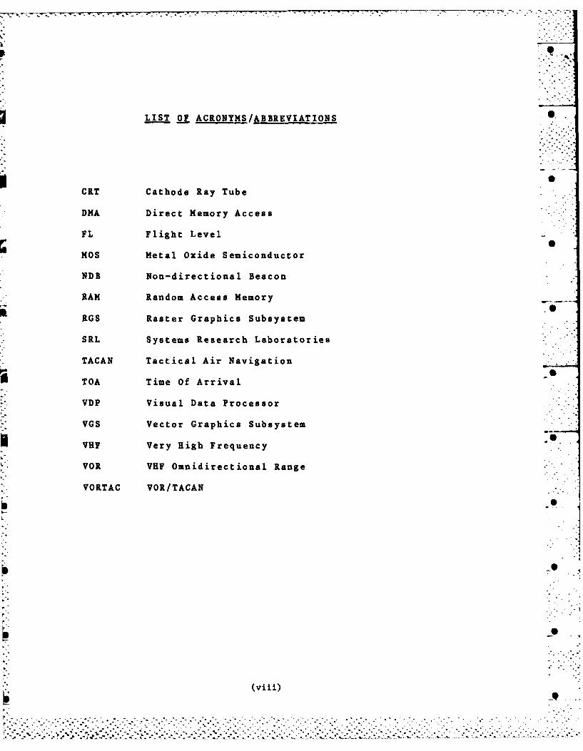
LIST O ACRONYMS/ABBREVIATIONS 0
CRT Cathode Ray Tube
DMA Direct Memory Access
FL Flight Level
Kos Metal Oxide Semiconductor
NDB Non-directional Beacon
RAM Random Access Memory
RGS Raster Graphics Subsystem
SRL Systems Research Laboratories
TACAN Tactical Air Navigation
41TOA Time Of Arrival
VDP Visual Data Processor
VGS Vector Graphics Subsystem
VHF Very High Frequency
VOR VHF Omnidirectional Range
VORTAC VOR/TACAN
- "'.
(viii)
... . . . . . . . .. . . . . . . .
. . . . . . . . . . . . . . . . . . . . . . . . . . . . ..--. - -. . - , ., . ,-. •, .. . .-. °. . ° .. .. -. o- ,• . . .
.""""""' "" " '""" ". ', " " " " " '"" "" " """ " " ""' "" . "" ."". .""''"" '""" '""" "Z " ' " ,-" " "" " " " "" "" """.". ... "-.
CHAPTER 1
INTRODUCTION
1.1 Introduction 0
The increasing speed and density of air traffic isforcing aviation agencies to adjust procedures and equipment toprevent air traffic controllers from becoming overtaxed. Thesolution to the overtaxing problem is to automate some portionof the controller's task.
Radar is employed to display the aircraft in a givenarea. The movement of the aircraft is followed and the expect-ed track is estimated. Potential aircraft collisions can only -
be detected by viewing the entire scene at once on the display.
By interposing a computer, further information about the air-craft can be displayed, such as flight number, altitude, pathand collision information. To further improve the benefits ofthe display, colour may be introduced to warn the air trafficcontroller of possible impending collisions. A simulation of a ._general area air traffic controller scenario was developed to -
examine the value of using colour to forewarn the controller ofpotential collisions.
In order to create an adequate simulation a graphicslanguage was needed on the system that would allow the movement -of the aircraft to approximate real-time. As the existing sets Sof routines were far too slow an entirely new package was writ- _ten and is fully described in Chapter 2 (the Graphics DisplayLibrary). Considerable care was taken to create a set ofroutines that would be most effective for the air traffic con-troller scenario. Future applications may also readily employthese routines. S
The general area air traffic controller simulation isdescribed in Chapter 3; the equations involved in moving theaircraft on the display are presented in Chapter 4; and theeffective real-time speeds of the aircraft are discussed inChapter 5. _
Information that is not as significant as the informs-tion on the main display must still be made available to theair traffic controller. It was necessary to devise a suitablesecondary display which is presented in Chapter 6.
The air traffic controller communicates with the pilots
of the aircraft in his jurisdiction so some interaction was
3 -9.°
*:: . ..- . . . . . . . . . . . . . . .
-2-
required to allow similar communication in the simulation. Thepseudo-controller can input to the terminal suggested speed andbearing changes and the computer executes these changes asthough the pilot followed the instructions precisely. Thisinteraction is described in Chapter 7.
A monochrome display of the general area air traffic 0controller simulation is used for comparison with the simula-tion using colour. The comparison is in Chapter 8.
Two types of display CRTs, a raster display and a vec-tor display, were available on which to implement the simula-tion. A comparison is made of the two display technologies in SChapter 9.
Consideration was given to possible areas for enhance-ment of the simulation for future applications. The enhance-ments are presented in Chapter 10. The conclusions of thestudy are presented in Chapter 11.
Using the new graphics display library of routines andthe special purpose routines the simulation was implemented andstudied. The full simulation program (atcint.c), listed inAppendix 2, displays the area background, moves the colouredaircraft across the screen, and allows air traffic controllerinteraction. Various sections of this program will be referredto and described throughout the report.
1.2 Equipment Used
The host machine is a DIGITAL PDP-11/34 computer with124k words of MOS memory, a 67 megabyte disk drive, a number ofterminals, and a NORPAK graphics system which consists of aRaster Graphics Subsystem (RGS) on a Systems Research Labora-tories (SRL) colour monitor, a Vector Graphics Subsystem (VGS)on a Kratos colour monitor, and the associated Visual Data Pro-_•cessors (VDPs). The VDPs convert program instructions intoformats recognizable by the monitors.
The VDP has memory for colours and blinking status.The memory is lk by 1k by 4 bits. Three of the 4 bits are for
* colour so 2 3 = 8 colours are possible. The fourth bit is for Sthe blink status. The VDP includes a video lookup table whichstores the representation of a large number of colours, howeverthe memory still limits the choice of colours to be displayedto eight at a time.
The operating system is UNIX with C as the programminglanguage [2], [23].
. .".. .. .
- 3
CHAPTER 2
GRAPHICS DISPLAY LIBRARY
2.1 Introduction
The graphics display library is a series of routinesthat provide a means of defining what will be on the colourdisplay (The Visual Data Processor (VDP) controlling a RasterGraphics Subsystem (RGS) and a Vector Graphics Subsystem(VGS)). The routines are written in the C language runningunder UNIX on a PDP-11/34 computer. When a program to create adisplay is compiled, this library of display routines is ap-pended to the compiled main program. This display programwould have a number of calls to a subset of these libraryroutines.
The system of display routines was developed to improvethe speed of response time over the NORPAK-supplied routineswhich were originally written for TELIDON. These routines werevery general and had no optimization for the high resolutionVDP. Some of the more complex TZLIDOM routine displays (espe-cially those involving arcs) took up to five minutes to drawcompletely. In order for the air traffic controller simulationto be effective the simulated aircraft must move in a realisticmanner. Also, when interactive changes are input these changesmust be effected within seconds. As the TELIDON routinea could ..not react sufficiently, new routines were required. •
The library of routines developed contains softwarethat is less general purpose and more restricted than theTELIDON oriented software. The TELIDON software allows sec-tions of display to be added by user interaction. The newgraphics display library deals only with fixed format displays. 0The basic content of the display must be predefined so onlythose predefined components may be altered, and only theircolour, location, blink, intensity may change. Due to theserestrictions there is much less overhead processing requiredfor each function with the new graphics display library. Adisplay involves displaying a collection of groups. For the 0purposes of the air traffic controller simulation all informa-tion on the screen can easily be predefined. Once these com-ponents, or groups of information are defined all the subse-quent changes are just minor changes to these groups. Changesinvolve colour or position modifications to aircraft.
The library of routines allows a large portion of thedisplay contents to be predefined and display changes to be
..... .
. .. .. -_ 7- T - .
-4- S
made quickly. This is because the graphical definitions reside 0in the VDP, waiting for portions to be selected for display.This minimizes the amount of data flowing between the host pro-cessor and the VDP.
This chapter assumes some knowledge of the UNIX operat-ing system and the C language. Syntax diagrams for using thegraphics display library routines are given in Appendix 9.
2.2 The Phases
The graphics display library (gdlib.c) is divided intofour distinct phases:
1) initialization phase2) subpicture definition phase3) group definition phase4) display phase.
Programs accessing the graphics display library mustacknowledge each of these phases by using some instructionsfrom each of these phases. The descriptions of the phases Lhatfollow indicate the minimum number of instruction accessesallowed in each case. A group defines a distinct attribute onthe display, for example a vector or some text. Group informa- Stion may be changed or updated by edit commands. A subpictureis a combination of display attributes which are treated as aset. Subpictures are used if the same set of attributes are tobe repeated throughout the display.
2.2.1 Initialization Phase
The initialization phase consists of a call to gdin-ito. This routine initializes variables concerned with keep-ing track of which subpicture or group is being described, ini- 0tializes the terminal and initializes the character spacing.It is in this phase that the user decides whether to use theRGS (unit 0) or the VGS (unit 1). The unit value defaults to 0but may be set to 1 if desired.
2.2.2 Subpicture Definition Phase ""
The subpicture definition phase immediately follows theinitialization phase. It is not necessary to have any subpic-tures defined but a call to gdsubend() to end the phase is _required. There may be many subpictures defined; each onestarts with a call to gdsubopn() to open the subpicture and
.--- , " - - . s . . . ".. - - .. " - ' . a . -
-5-
ends with a call to gdsubcls() to close the subpicture. Once 0subpictures have been defined they cannot be edited. A subpic-
ture describes a picture element that will likely be repeatedmore than once in the display. Subpictures would be used main-ly to define special symbols, (eg. the symbol for an air- ...
craft)..
The body of the subpicture consists of any combinationof calls to gdcolro, gdintso, gdblnko, gdaset), gdcseto,gdvecto, gdiveco, gdtext(. These routines are definitioncommands and will be described later. Calls to gdcolr() arenot recommended on the VGS because considerable time is takento switch colours. When the VDP displays the screen picture itsorts by colour then displays all of one colour at a time.However, colours in subpictures cannot be accessed to sort.
A subpicture is restricted to 1024, 16 bit words ofdata in total. This poses no practical limitation on the sub-
picture size. For example a subpicture could set up more than
500 vectors or more than 1000 characters. The call to gdsu-bend() is required whether there are any subpictures defined ornot.
2.2.3 Group Definition Phase "
The group definition phase immediately follows the sub-picture definition phase. This phase is terminated by a callto gdgrpendo. At least one group must be defined. Thesegroups contain the commands that describe what will be on thedisplay.
A group definition consists of zero or more calls togdcolro, gdints(), gdblnko, gdaset(), gdcseto; and one ormore calls to any one of the three types of drawing commands:gdvect() or gdiveco, gdtext(), gdsubpo. A group can have oneof the text, vector or subpicture drawing commands but not more 0than one type. The drawing commands gdvect() and gdivec() maybe intermixed since they are both vector drawing commands eventhough the latter draws invisible vectors.
The calls to the definition commands simply reset thedefault attributes assigned to the group. When the gdgrpend() •call is made the attributes are filled into the group headeralong with the drawing commands, and output.
2.2.4 Display Phase
TiThe display phase immediately follows the group"". .
'-. -".. -'-'2.'.2.''-/ 22 22 2• 2-2 T I 'T -T 2 '2 . 'i -' 2-2 "2 '1 " 2-". i " -T .. . . '..-. -T -2 " . 2. . . 22 - - "
..................-:-...-.. .-.-.. .-....... '-.-.........--.-."...."2.2-/2"2'.-.-'2" "i . ,.-"2./ "''2...""2..-2-.
-6-
definition phase. This phase is terminated by another gdin- S
ito. If the calling program terminates without another gdin-ito then the picture will remain displayed until the screen isaccessed by another program.
This phase consists of calls to gdattacho, gdupdateo,gdcursoro, gdpoll(), gddisply() and calls to any of the edit 0group which may be made in any order, depending on application.
Descriptions of all of these routines follow.
2.3 The Commands
The commands are the actual routines that will becalled by the user's program to draw on the display. With thisconcise set of commands any type of display may be drawn, how-ever the set is more specifically useful for line drawings -
rather than filled or solid drawings.
2.3.1 Control Commands
gdinit(): 0This routine sets up a line of communication with theVGS or the RGS. Variables, the terminal and charac-ter spacing are initialized.
gdsubopn():This routine indicates that a subpicture definitionwill begin. The routine checks that the phase iscorrect to open a subpicture, and that there is notan unclosed subpicture. Once a subpicture is definedit cannot be edited. The routine keeps track of thenumber of subpictures.
gdsubclso: 0This routine indicates that the current subpicturedefinition will end. The routine checks that thephase is correct to close a subpicture and that thereis indeed an open subpicture to close. If so, thesubpicture information is written to the VDP.
gdsubend()This routine marks the end of the subpicture defini-tion phase. The routine checks that all subpicturesthat have been opened have been closed. If not, anerror is indicated. If the state is correct to endthe subpicture phase it is changed to group phase andthe group header information is set up so that thegroup definition phase may begin. Initially the
. .- .
..................... ............................................ ............
-7- 0
group colour is red, the intensity is full, the 0screen is not blinking, the drawing pointer is set to(0,0), and the small character set is in use.
gdgrpopno:This routine is called to begin definition of agroup. It checks that the phase is the group defini-tion phase; and it checks that there is not an un-closed group. The routine keeps track of the numberof groups defined. Each group may define text, orvectors (visible and invisible), or subpicture calls;but may not define a combination of these.
gdgrpcls(): 0
This routine closes the definition of a group. Theroutine checks that the phase is correct to close agroup definition and that there is indeed an opengroup to close. If so, the number of drawing commandsin this group is recorded, and the group information 0is sent to the VDP.
gdgrpendo:This routine marks the end of the group definitionphase. The routine checks that all groups that havebeen opened have been closed. The phase is checkedand if it is correct (phase 3 - group definition - Sphase) then the program may proceed to the displayphase.
gdupdateo:This routine updates the display with the given listof groups. The groups are presented in an array ,along with the number of groups included. The infor-mation is sent to the VDP. If the program is not inthe display phase an error is indicated.
gdpoll():This routine polls for the co-ordinates of the cur- Ssor. The cursor is attached to the trackball. The xposition and the y position of the cursor are eachread into corresponding variables. If the program isnot in the display phase at the time of the call theerror is indicated.
gddisplyo:This routine turns the display refresh on or off. Ifthere are to be a series of edits to the display itmay be desirable to turn the refresh off until all ofthe edits have been completed and then turn the re-fresh on again. If the program is not in the display 0phase at the time of the call an error is indicated.
o .-S
-8- 6
gdcursoro:This routine turns the trackball cursor on or off.The program must be in the display phase.
gdattacho:A group defines the shape and size of the cursor, andin order to display the cursor that group must be 0selected for display through the last update command(gdupdateo). The routine attaches the trackball tothe group defining the cursor. The gdaset() value inthe defining group is the actual position of the cur-sor. The information is sent to the VDP. The pro- .gram must be in the display phase. 0
2.3.2 Subpicture and Group Definition Drawing Commands
gdcolro:This routine defines the subpicture colour if in thesubpicture definition phase, or changes the colourvalue in the group header if in the group definitionphase. If not in either of these phases an error isindicated. The possible colours are:
0-red1 - orange2 - amber3 - yellow4 - green.
(Note: the RGS allows variations in blue and purpleas well, but as the aim was to make the RGS and VGSwork with the same library of routines, the RGS had Sto limit its colours to those of the VGS.)
gdintso:This routine defines the intensity of the informationdisplayed on the screen if in the subpicture phase,or changes the intensity value in the group header if 6in the group definition phase. If not in either ofthese phases an error is indicated. The possibleintensities are 0 to 17 octal with 17 being fullintensity and 0 being invisible. The parameterpassed to this routine should contain the intensity.
gdblnko:This routine indicates whether or not the subpictureelements will blink if in the subpicture definitionphase; or the routine changes the blink status in thegroup header if in the group definition phase. Ifnot in either phase an error is indicated. The twostates of blink are:
0 - do not blink
.......... ......... ...................-
-9-
1- blink.
gdaseto:This routine sets up the absolute x, y position fromwhich the next information will be drawn. In thesubpicture definition phase the x, y set is defined.In the group definition phase the x, y set is modi-fied in the header. If in neither of the phases, anerror is indicated. The values of x and y must begreater than or equal to 0, and less than or equal to • .1023. Each group can only do one absolute position . °"set. If a group does not do an absolute position setthen the set from the immediately preceding group isused. 6
gdcset():This routine defines the subpicture character setchoice if in the subpicture definition phase, ormodifies the character set choice if in the group " "
definition phase. If in neither of these phases, an Serror is indicated. The character set choice is:
0 - small %1 - large.
gdvect():This routine sets up a series of one or more relative 0vectors to be drawn one after the other. The arrayof vectors may be introduced in either a subpictureor a group. If the program is neither in the subpic-ture definition phase nor the group definition phasean error is indicated. The array of vectors and thesize of the array must be given. S
gdiveco:This routine sets up a series of one or more invisi-ble relative vectors to be drawn one after another.The array of vectors may be introduced in either asubpicture or a group. If the program is currentlyneither in the subpicture definition phase nor thegroup definition phase an error is indicated. Thearray of vectors and the size of the array must begiven. Invisible vectors may be used if one requires .the x, y pointer position to be at another locationon the screen but does not wish to start anothergroup.
gdtext():This routine defines a text string to be written onthe display, in either a subpicture or a group. Ifthe program is neither in the subpicture definitionphase nor the group definition phase an error isindicated. The string of characters will be sent as
-9
.. -" '."./," -..-.. - '. =." . .. '- -. " . ' " . . .. .. .. . . ..- " " " "-.." " •" ".S ... ...-... - ... ... ... ,. -........ ....-..... .....-..... • .....-....................... _.. ..
-10- 0
follows: gdtext("ABC", 3). The string and the Slength of the string (including blanks) must be indi-cated. Note: the string can also be given in anarray.
gdsubpo:This routine indicates which subpictures will beaccessed from the present group. If the program isnot in the group definition phase an error is indi-cated. As subpictures were defined they were num-bered, starting at 1. The subpictures to be accessedare to be indicated using these numbers which areintroduced in the group as an array. The size ofthis array must also be given.
2.3.3 Group Edit Commands
After the screen has been displayed portions may need "
changing. This is done by editing the desired groups and thenredisplaying the screen using the gdupdate() command. In eachedit cormand the group to be edited must be indicated, alongwith the new value(s) of what is being edited. Groups werenumbered from 1 as they were created, and are identified usingthis number. The edit type must also be given:
0 - if the template is to be edited1 - if the template and the display are to be
edited.When the display is edited (edit type 1 1) an automatic updateof the display occurs.
gdedcolro:This routine edits a group's colour.
gdedints():This routine edits a group's intensity.
gdedblnko:This routine edits whether or not the information inthe group will blink.
gdedaseto: -This routine edits the group's absolute x, y pointer Sposition.
gdedcseto:This routine edits the group's choice of charactersize.
gdedvecto:This routine edits a number of vectors (0 or more) in
S- .
-11i- S
a given group. The vectors to be modified arepresented in an array the size of which must begiven. Each array must be of contiguous vectors,with the number of the first vector to be changed, -given. There may be more than one call to gdedvect()for a given group since all vectors to be changed arenot likely contiguous.
gdediveco:This routine is like gdedvect() but the vectors areinvisible vectors.
gdedtext():This routine edits a series of contiguous characters 0of a text string. The number of the first characterof the series must be given to the routine along withthe number of characters in the series to be changed.Of course the new string of characters must also begiven. Since the text edit is a one for one charac- -ter replacement the new string must be the samelength as the old string. There may be more than onegdedtext() call per group.
gdedsubpC:This routine edits the subpictures to be called from .the group. The subpictures are presented in an ar- . ]ray, the size of which must be given. The subpic-tures to be edited must be contiguous, and the number . -of the first subpicture of the set must be given.There may be more than one gdedsubp() call per group. "
2.4 Special Purpose Routines
The following two routines are not part of the libraryitself but their functions are very basic and therefore theroutines are appended to applications programs along with the Sgraphics di,/play library. The special purpose routines arewritten us-*.n the graphics display l'ibrary routines.
2.4.1 Dashed Lines
Part of the background display for the air traffic con-troller scenario requires dashed lines. Several graphicssoftware packages include a routine to do this but as thegraphics display library consists of the more fundamental draw- .ing commands the routine has been written separately. The 0routine may be of use to programs other than the air traffic -
controller simulation program so it was written as an external
* . . . . * * . . "..** . . * .*
-12-
subroutine. 0
The dashed routine, called gddash.c (Appendix 5), ispassed the x and y coordinates of the position at whi4.h theline is to begin and of the position at which the line is toend. The dashed line is created by drawing a visible vectorand then an invisible vector sequentially until the line iscompleted. The length of the dash is constant no matter whatthe slope of the line is. There are slight differences in theimplementation of the basic routine depending on whether theline is to be of a horizontal nature (-I < slope < 1) or of avertical nature, or whether the line is to be drawn left toright or right to left if horizontal, or top to bottom or bot-tom to top if vertical.
2.4.2 Circles
The ability to draw circles is another general require- -
ment that may be desired by other programs at a future date sothe circle routine is separate from the air traffic controllersimulation program.
The circle routine, called gdcirc.c (Appendix 6), isgiven the coordinates for the center of the desired circle, the 0radius of the circle (where a radius of 512 units is the larg-eat possible circle), the number of vectors used to draw thecircle (the more vectors the smoother the curve), and thenumber of vectors to draw before skipping a vector (if a dashedcircle is desired). With this information the routine followsa loop that calculates and writes the vectors to the display,creating the circle.
2.5 Summary
The library routines are simple, straightforward andeasy to use.
Although the display library itself does not includespecialized routines such as the routine to draw dashed linesand the routine to draw a circle, using the routines in the Slibrary, it is a straightforward matter to write any requiredspecialized routines. Once these routines are written they canbe appended to the calling program or even added to the displaylibrary.
Consistency among the library routines was emphasized. SFor example all information for vectors, groups, strings, andsubpictures must be presented as arrays. The processing
S-i-,-
-13-
overhead has been minimized to allow programs using the libraryroutines to run with as little delay as possible. It is bene-. .ficial that the same library of routines can be used to display .on the raster CRT or the vector CRT, with the differences in -manipulating the two CRTs transparent to the user. The library ..-
of routines provides an effective base for display depiction. .-.
Appendix I is a complete listing of the library ofdisplay routines.
S• .
t, •
.- .- -.;.iS
................ .. *. .. .. .. .. .... .. ..
. . , ,°. ..- .
.. . . . . . . . . . . .
-15 -
CHAPTER 3 -
THE AIR TRAFFIC CONTROLLER SCENARIO
3.1 General Area Air Traffic Control-ley (Jurisdiction andDuties)
The purpose of the air traffic controller is to ensurethe safe, orderly and expeditious flow of air traffic so he 0must ensure that aircraft do not come close enough to eachother to pose danger of collision. Secondary objectives of theair traffic controller include avoiding delays to aircraft,reducing fuel consumption and minimizing noise to people on theground.
The goal of maintaining a safe flow of air traffic is 0
achieved by preserving separation standards. The separationstandards are: aircraft at the same horizontal level may notpass within three miles of one another; and aircraft separatedby less than three miles horizontally must be at least 1000feet apart vertically. If two aircraft come within the dis-tance of separation standards they are within "airmiss" dis-
tance. Airmisses are recorded as they may be of interest ifthere are adverse effects on the flight crew or if anyavoidance manoeuvre injures crew or passengers or damages theaircraft. [21I
Air traffic control consists of more than one task,carried out by different controllers. For one task, involving -.ground movement control, the controller is responsible fordirecting any traffic (aircraft, cars, fire engines, towingvehicles) using the runways and taxiways. For another task,involving approach control, the controller is concerned withthe horizontal and vertical separation of the aircraft, and the . Sflight paths which they should follow to approach the runway inthe immediate vicinity of the airport. There are other typesof controllers but only one more controller task will be dis-cussed: the task considered for this study of general area airtraffic control.
The colour graphics developed for the study are intend-ed to assist this general area air traffic controller in histask to control all aircraft in a given area. Usually the gen-eral area air traffic controller views a 15 nautical mile ra-dius, but his responsibilities are normally for a 10 nautical
mile radius. He is situated at the center of his circle of Sresponsibility, and all aircraft within the 10 nautical mileradius circle, at any altitude, must allow control by him. All
. ,...,. ...
. . . . .. . .. .
16 -
aircraft outside the 10 but inside the 15 nautical mile radius 0circle that are flying over 6000 feet must also allow controlby the general area controller. Aircraft, usually small air-craft, flying under 6000 feet are in uncontrolled air space.They must follow the standard rules but only use the controllerwhen they require assistance. These small aircraft must bevisible to the air traffic controllers by radar so that other •aircraft under control can be advised of their presence ifnecessary.
3.2 Background Display
In order to aid the general area air traffic controllera suitable display background is required. Figures 1 through 6exhibit the background.
The background display contains the 10 and 15 nauticalmile radius circles of interest to the air traffic controller.On the outer circle are the degrees relative to north that areused by the controller when determining the direction in whichthe aircraft is going. The beacons towards which aircraft flyare indicated. As the area depicted is the Ottawa area thereis a TACAN (Tactical air navigation) beacon, a VORTAC (VHFOmnidirectional Range/TACAN) beacon, and two non-directionalbeacons (NDB) [151. The NDB's, or omnidirectionaltransmitters, give directional information. The location ofthe beacons is known, the direction of its emitted signal canbe determined, and therefore the aircraft bearing can be calcu-lated. The TACAN is a military omnibearing and distance meas-urement system. Aircraft range can be determined from thepulse emitted from the beacon. VORTAC is the colocation of VORand TACAN. VOR is similar to NDB so the bearing and range canbe determined with the VORTAC. Aircraft fly along airways butin the Ottawa area the airways overlap considerably so the air-way is depicted by a line down its center and by the dashedline as shown on the display.
In order to give the controller some reference to thepositions of the aircraft the major terrain features are denot-ed. These include the Ottawa River, the Gatineau River, theRideau River, and some of the Gatineau hills.
Air traffic controllers receive weather reports on acontinual basis by radio transmissions from meteorologists. Inorder to assist the controller the more important weatherfronts are included on the display. A very slow moving weatherfront has been indicated on the Ottawa area display along withthe direction the front is moving. The weather front does notmove during the simulation as they only travel from 10 to 25miles per hour, depending on the type of weather mass, and
. :. .. .. . . . . . . ..
"" " .' " "' """ '" " ' " " "- ". >" "" >''" ".' " - . '" > " " "i "' '- " "." " " " .''i " !-' .: i . . . "' >
-17-
this would not be noticeable during the one or two minute simu- 0lation. The weather information is included to indicate theamount of clutter it adds to the display. Different patternswould represent different types of weather and these would beknown to the air traffic controllers.
The runways and the control tower are, of course, in- -
cluded in the background display as they are very important tothe air traffic controller.
The details included in the background are the mostdistinctive characteristics of the Ottawa area. It would notbe difficult to include other items, for example, military test -
sites over which to avoid flying, or other airports in thearea.
3.3 Opinions on the Use of Colour
The availability of colour graphics has led to ques-tions of its use in air traffic control. Would colour graphics. -- -be cost effective? Would colour hinder the air traffic con-troller more than aid him? Would colour be redundant? What isthe most effective use of colour? Several authors have com-mented on these questions.
Lucas [161 states that it is well known that the humaneye can distinguish differences in colours more readily thandifferences in grey levels so colour should be considered.
Christ and Teichner [7] tested the effects of colour on -. .visual search and identification performance. The results ledto the opinion that colour is superior to size, brightness, andshape as unidimensional target features, but inferior to al-phanumeric symbols, especially with increased task complexity.Unidimensional means differing from each other in terms of onlyone stimulus dimension; all other attributes of the targets Sare held constant. The reason colour seemed inferior to al- *
phanumeric symbols is perhaps the fact that the users were fam-iliar with the practice of identifying alphanumeric symbols.The general feeling of the users was that colour in displays isless monotonous, and that it produces less eye strain and fa-tigue. However, the authors felt colour interfered with the Sability to discriminate other target dimensions in that colourdistracts the observer so that he does not attend to otherevents on the screen.
Hopkin [12] suggests colour may be used to indicate:1) climbing or descending or level aircraft, S2) aircraft's height band,3) aircraft being handed over to another controller,
. . - .. . . . . . . . . . . . .
-- ..
-18-
4) eastbound or westbound aircraft, 05) aircraft on potential collision courses,6) supersonic or subsonic aircraft,7) aircraft requiring co-ordination or liaison.
Hopkin feels none of these uses is obviously supreme, howevernone of them have been fully tested for effectiveness. He sug-gested that some of the demonstrated advantages of colour maycome aot from its value as a visual code but from enhancedmotivation, attention and articulation associated with itspleasing appearance. Apparently air traffic controllers parti-cipating in the testing of a visual search task showed a signi-ficant improvement using colour instead of monochrome displays,by reducing search time, but not by increasing accuracy. Itwas recommended that colour as a non-redundant code should betested in cluttered display conditions as perhaps then thebenefits of colour would show up.
Hopkin also concluded that people often believe theywork better with colour displays but this belief, being illuso-ry, could also be dangerous because they may rely too heavilyon colour. The air traffic controller may rely too heavily onthe screen indicating problems in red, for example, and there-fore miss a problem that did not show in red. The controllermay scan the screen less frequently and become reliant on thered indicators.
If the colours chosen for screen items are not optimumthen items in different colours may seem more disimilar thanthey are and items in the same colour may be equated more thanthey should be. Blinking information may be used instead ofcolour to attract the attention of the air traffic controller.Although blinking information could be found quickly it could 3prove irritating and distracting if it persisted for some time.
Hopkin concluded colour graphics is much more costlythan monochrome graphics so the improved performance of the airtraffic controllers must be significant before colour should beused. He forecasts studies will continue into the various uses Sof colour, and their cost effectiveness. There is an increas-ing availability of cheaper raster technology displays primari-ly due to decreasing prices for RAM.
3.4 The Use of Colour to Avoid Collisions S
One of the most important areas in which to use colour. is in averting potential aircraft collisions. The general area
air traffic controller situation has been chosen to demonstratethe effectiveness of using colour to highlight potential Sdanger. The colours available are green, red, orange, amberand yellow. The raster graphics subsystem has potential for
~7.* . *.*.*. ...-
* - .- r r: .- o.o
-19-
blue and purple but the vector graphics subsystem does not. As Sthe two subsystems are to be treated the same to allow a com-parison only the vector graphics subsystem colours are used.(When comparing the vector and raster subsystem it is ack-nowledged that the raster subsystem has the added advantage ofadditional colours.) Green is quite different from the otherfour colours so it has been chosen for the background. Theaircraft are red, orange or amber. Yellow has been chosen forthe runways and control tower, so they would stand out from thebackground. Yellow may be too close in colour to orange andamber but the choices were limited.
The air traffic controller views the display containingthe position information of the aircraft and if he observes apotential collision he will notify the aircraft involved of arecommended new bearing and new speed to follow. The controll-er can then watch the effect of the change on the display. Thephotographs of the display shown in Figure 1 and Figure 3 showtypical settings of the colour displays. The aircraft are dep-icted by a "+" associated with a flight number and a flightlevel. The flight number includes two letters indicating theairline and three numbers identifying the aircraft, for example"AC 123". The flight level is a number representing hundredsof feet, for example 80 would mean 8000 feet. The flight in-formation is depicted in the same colour as the aircraft.
It was decided that the best way to use colour to makethe air traffic controller aware of potential collisions was todisplay in red all aircraft within airmiss distance of anotheraircraft. Aircraft within two times airmiss distance of anoth-er aircraft would be displayed in orange as they may soon ap-proach a dangerous separation. All aircraft not in any poten-tial danger would be displayed in amber.
When determining the colour of the aircraft only thehorizontal airmiss distance is considered. As the purpose ofthe study is to evaluate how well colour informs the air traff-ic controller of aircraft in potential danger it was decided to •assume aircraft at any altitude were to be considered. Thereis the requirement to warn pilots of horizontal airmiss infrac-tions even if the altitudes are different because the heightinformation may be in error or the aircraft might be in theprocess of climbing or descending. Using red to indicate theaircraft in the most immediate danger was the obvious choice as •air traffic controllers normally associate red with danger.Red is the colour most likely to attract their attention.Amber and orange are colours associated with caution. Ambercontains less red than orange does so is not likely to attractthe air traffic controller's attention as readily as orange.The varying amounts of red content in the colour of the air- ..craft imply correspondingly varying amounts of attention re-quired.
- " " " / ' ' '' i °" °o o ., . .." "S
- 20 -
As aircraft travel over the display they change to red,orange or amber as their distances from other aircraft change.Eight aircraft are depicted in one simulation. With only eightaircraft the air traffic controller can probably determine inadvance which ones will turn red. However when twenty-fouraircraft are depicted there are too many aircraft to scan sowithout the benefit of the aircraft turning red when in poten-tial danger some possible airmiss situation might be over-looked. Even with only eight aircraft the occasional near missmay be overlooked so the addition of colour is a definite im-provement. The analysis of the benefits of a colour displaycompared with a monochrome display is presented in Chapter 8.
3.5 Obtaining Position Data in Reality
In a real situation, rather than simulation, the loca-tions of the aircraft are obtained from radar. A rotatingantenna sends out pulses and measures the time for the pulse toreturn. On the radar screen this information is plotted as adistance from center. Some pulses returned may be false infor-mation if the pulses are returned from weather masses, groundclutter, or buildings. To minimize this false alarm rate thesignal threshold should be set high enough to eliminate most ofthe false pulses but low enough to not block aircraft informa-tion.
The aircraft position data can be extracted from theradar screen manually with the advantage that false pulse re-turns can be detected and discarded by experienced operators.The disadvantages are the chance of human error, and the in-feasibility of manually entering the data in the computer.
Plot extractors can also be used to retrieve the radar
screen position data. This electronic method cannot detect allfalse alarms but human error is eliminated. A track initiatorindicates the aircraft track or path and only aircraft would 0have a track so other pulse data can be eliminated. Once theradar aircraft position is known, the format of this data canbe used by the computer and with minor calculations betransformed to information to be put on the display.
* . . . . . . . . .~ . . *. . . -*' * , --
. . . . . . . . . . .i:!
. .. . 1 * ilA** *."
21 .
CHAPTER 4 0
CALCULATIONS FOR A MOVING DISPLAY
4.1 Path Calculations
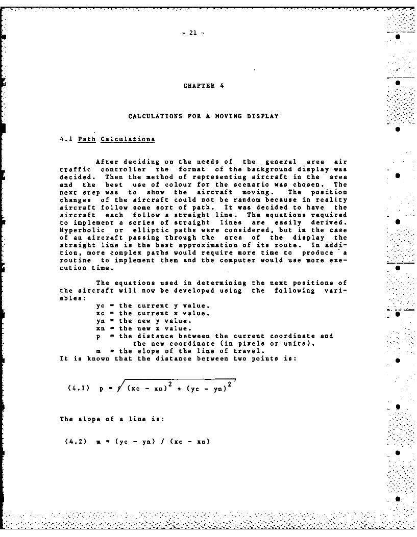
After deciding on the needs of the general area airtraffic controller the format of the background display wasdecided. Then the method of representing aircraft in the area Sand the best use of colour for the scenario was chosen. Thenext step was to show the aircraft moving. The positionchanges of the aircraft could not be random because in realityaircraft follow some sort of path. It was decided to have theaircraft each follow a straight line. The equations requiredto implement a series of straight lines are easily derived. SHyperbolic or elliptic paths were considered, but in the caseof an aircraft passing through the area of the display thestraight line is the best approximation of its route. In addi-tion, more complex paths would require more time to produce aroutine to implement them and the computer would use more exe-cut ion time. S
The equations used in determining the next positions ofthe aircraft will now be developed using the following vari- "'ables:
yc - the current y value.xc - the current x value. 0yn - the new y value.xn - the new x value.p - the distance between the current coordinate and
the new coordinate (in pixels or units).m - the slope of the line of travel.
It is known that the distance between two points is:
Yn) 2 ".(4.1) p (xc xn)2 + (yc yn)
-S
The slope of a line is:
(4.2) m = (yc - yn) / (xc - xn)
. . o .
. . . . . . . . . . . .. . . . . . . . . . . . . .
-22-0
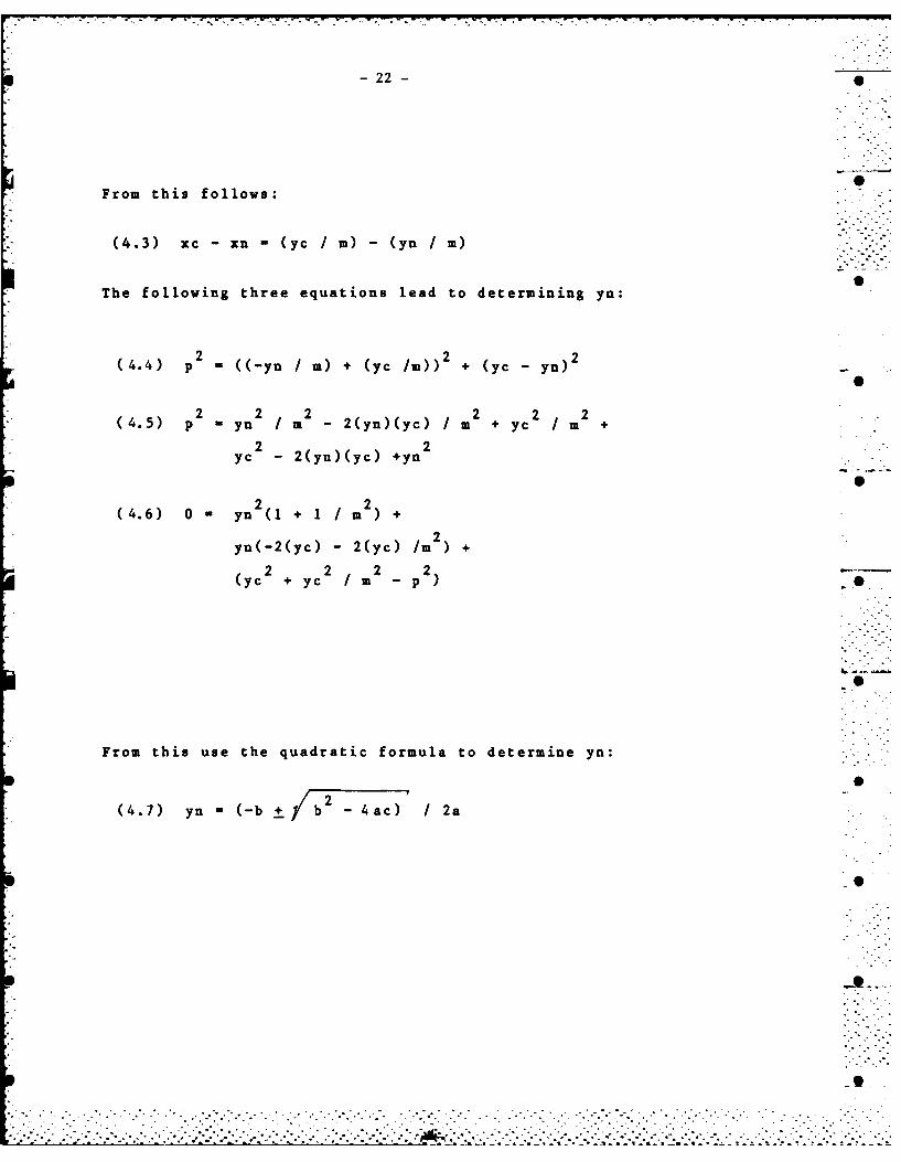
0From this follows:
*(4.3) xc -xn -(yc m) -(yn m)
The following three equations lead to determining yn:
(44 p 2 = ((-yn ,~m) + (yc /m)) 2 + (ye - yn) 2
(4.5) p 2- yn 2 m 2- 2(yn)(yc) Im 2+ yc 2 m 2+
2 2ye 2(yu)(yc) +yn
(4.6) 0 - yn 2(1 + 1I m 2) +
yn(-2(yc) -2(yc) /
2 2 2 2(ye + ye m -p)
From this use the quadratic formula to determine yn:
2*(4.7) yn =(-b + /b -4ac) /2a
-23-
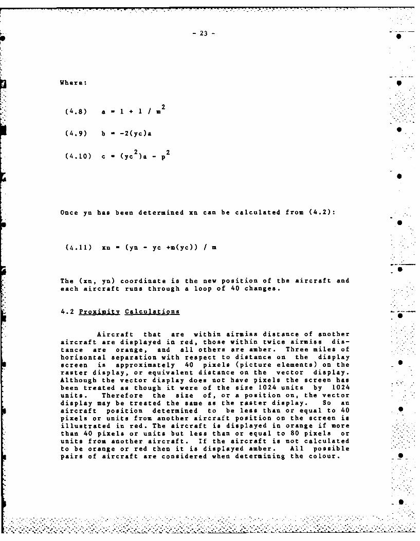
Where: 9
(4.8) a 1 1 + 1 / 2
(4.9) b = -2(yc)a 0
(4.10) c - (yc2 )a - p 2
Once yn has been determined xn can be calculated from (4.2):
(4.11) xn = (yn - yc +m(yc)) / m
The (xn, yn) coordinate is the new position of the aircraft andeach aircraft runs through a loop of 40 changes.
4.2 Proximity Calculations
Aircraft that are within airmiss distance of anotheraircraft are displayed in red, those within twice airmiss dis-tance are orange, and all others are amber. Three miles ofhorizontal separation with respect to distance on the displayscreen is approximately 40 pixels (picture elements) on the _raster display, or equivalent distance on the vector display.Although the vector display does not have pixels the screen hasbeen treated as though it were of the size 1024 units by 1024units. Therefore the size of, or a position on, the vector "display may be treated the same as the raster display. So anaircraft position determined to be less than or equal to 40 ,pixels or units from another aircraft position on the screen isillustrated in red. The aircraft is displayed in orange if more ---
than 40 pixels or units but less than or equal to 80 pixels orunits from another aircraft. If the aircraft is not calculated -
to be orange or red then it is displayed amber. All possible .pairs of aircraft are considered when determining the colour. S
0-
-25-
CHAPTER 5
RUNNING SPEED
5.1 Speed of Aircraft
The speeds at which the aircraft appear to be travel-ling are in fact dependent on the time taken to do the calcula-tions for a moving display, execute the front-end graphics 0routines, and go through the Visual Data Processor (VDP). Onthe Raster Graphics Subsystem (RGS) the front-end graphicsroutines take more time as there is an added package to makethe RGS operate like the Vector Graphics Subsystem (VGS). Asit was not known before programming the simulation how much ..time would be spent in each of these phases it was not known in 6advance at what speeds the aircraft would appear to travel. Avariable ("p") for each aircraft has a value indicating thenumber of pixels or units to be skipped with each aircraftposition move. The "p" values were modified to make the speedsof the aircraft on the raster system appear realistic. Speeds -
of aircraft can be changed dynamically through interaction as 0described in Chapter 7.
The effective speeds of the aircraft on the RGS werecalculated as follows. The time taken for all the aircraft tomove 40 times was 103 seconds. The radii of the distance cir-cles in the background display are known, giving the estimate 0that 6.3 inches represents 22.9 miles. This ratio is used todetermine the distance in miles each aircraft travelled, know-ing the number of inches it covered on the screen. 103 secondsis .0286 hours so dividing the miles by this value will givethe speed in miles per hour. The speeds of the following six
aircraft for reasonable "p" values are as follows:AC 441 covered 5.0 inches which represent 18.2 miles
therefore travelled at 636 miles per hour.EA 123 covered 7.6 inches which represent 27.6 miles
therefore travelled at 965 miles per hour.GX 741 covered 8.1 inches which represent 29.4 miles
therefore travelled at 1028 miles per hour.AC 164 covered 2.0 inches which represent 7.3 miles
therefore travelled at 255 miles per hour.AC 111 covered 4.3 inches which represent 15.6 miles
therefore travelled at 545 miles per hour.Note that GX 741 travelling at 1028 miles per hour is fasterthan a normal aircraft speed. This fast speed was included toallow a wide range of travelling speeds to be viewed.
Similarly the effective speeds of the aircraft on the
7 . •.
- 26 -
VGS can be calculated. The aircraft each moved the same dis-tance and the same number of times as on the RGS, but theelapsed time was only 55 seconds (or .0153 hours). The elapsedtime is less because the series of routines required to makethe graphic instructions acceptable for the RGS are not re-quired. The speed of the same six aircraft without alteringthe "p" values are as follows:
AC 441 travelled at 1191 miles per hour.EA 123 travelled at 1804 miles per hour.GX 741 travelled at 1922 miles per hour.AC 164 travelled at 477 miles per hour.AC 111 travelled at 1020 miles per hour.
The speeds are too fast to be realistic but the "p"variables that alter the effective speeds were not changed toallow a more accurate comparison between the vector and rasterdisplays. If parallelism with the raster display was notnecessary the "p" variables could easily have been altered tomake the effective aircraft speeds on the vector display more 0realistic. If a real air traffic control situation, ratherthan a simulation, was in effect then the VGS would give a moreaccurate depiction than the RGS since position informationreceived from radar, for example, could be displayed with lessdelay on the VGS. The RGS would always be displaying the trueaircraft positions a few seconds late, since the extra time 0would be required to process the data through the front-endroutines described in section 9.1.
5.2 Improved Running Speed by Other Methods
Delays in processing new aircraft position data couldbe the result of:
1) The mathematical calculations,2) The front-end graphics routines (in the case
of the RGS),3) The VDP firmware routines.
In the event that delays caused by 1) might be significant,methods of obtaining future aircraft positions other thanthrough calculations once the aircraft are ready to move, wereimplemented. The calculations were completed in advance andall future moves were stored in a database to be retrieved fromdisk when needed. As an alternative, should the disk retrievaltime prove to be significant, the database of information formoving the aircraft was stored in an array in the simulationprogram. Neither of these approaches proved to be necessary asthe limiting factor turned out to be the VDP firmware routinesand the front-end graphics routines.
. ." ... . .
- 27 -
5.3 Timings
Since decreasing the time spent on the calculations tomove the aircraft did not affect the effective speed of theaircraft, the time spent in the VDP and in the front-end graph-ics routines was evaluated. •
The UNIX "time" command was used to time the movingaircraft program (atcint.c, Appendix 2) running on the RGS. Nointeraction was effected during the timing. The timings wereas follows (minutes:seconds):
real --- 1:50.0 0user --- 3.7sys --- 11.7
"Real" indicates the elapsed time; "user" indicates the timespent executing in user mode; "sys" indicates the time spentexecuting in system mode. The elapsed time measurement is ofgreatest interest. S
To assess the portion of this total elapsed time that .r
was spent in the VDP the moving aircraft program was run in away such that all the output that would go to the RGS VDP to beprocessed for the raster display was discarded as it was re-ceived. The front-end routines (section 9.1) were still in useduring this timing. The timings of the moving aircraft programrun under these conditions were as follows:
real --- 1:08.0user --- 3.6sys --- 12.2
Therefore approximately 42 seconds are spent waiting forsoftware to execute in the VDP.
Finally to determine the time spent in the front-endroutines (described in section 9.1) the moving aircraft program . .running on the RGS was timed as it discarded VDP output andbypassed the front-end routines. The resultant timings were asfollows:
real --- 7.0user --- 3.6sys --- 2.8
Without the VDP or the front-end routines there is, of course,no output to the colour display. However it is interesting tonote that so much time is spent in each of the VDP and thefront-end routines. The VDP takes 42 seconds of the program'srunning time and the front-end routines take another 61seconds; the actual running of the atcint.c program is only 7seconds.
The same "time" function determined the time required- .to run the moving aircraft program (atcint.c), with no interac-tion, for the VGS to be as follows:
S'.. .. ..
... .. .. .. .. .. .. .. .. .. .. . . - ......... ..
• - ~~~.'-o . . i.. .-... .. . .. . . . - . ••. -. • . -. o. . . • , . o• . * -7 ti . •' iS C C° •P -~ ,- * -* - . - .". .. - • •
-28-
real --- 55.0 0user --- 4.0sys --- 6.2
Of course the front-end routines described in section 9.1 arenot used for the VGS. Therefore the "real" time for running onthe VGS should be approximately 61 seconds less than the "real"time for running on the RGS. Indeed 1:50.0 minus 55.0 is 55.0 0seconds.
The above timings indicate why the general area air
traffic controller simulation is shorter on the vector display
than on the raster display. The time measurements noted above
demonstrate the computational penalties involved in complex
graphics, especially those involving raster systems.
S. ...
• -'
...................................
................. ~ - . . ... ... .. ... 2
-29-
CHAPTER 6
THE SECONDARY DISPLAY
6.1 The Secondary Display 0
In addition to the primary display depicting the movingaircraft, the air traffic controller may require supplementaryinformation, but to include information such as destination,speed or type of aircraft would clutter the main display. Forsupplementary information, air traffic controllers currentlyuse flight progress strips which are small strips of paper thathave the extra flight information written on them. A more con-venient technique is to use a secondary display that listsextra information about each aircraft. The secondary displaycan be displayed whenever the information is required so there Sis no need to fumble with bits of paper; and if changes in air-craft data occur the secondary display can easily be modified.A suitable secondary display has been presented and containsthe following information: (Appendix 3 is a listing of theroutine that draws the secondary display and Figure 7 shows theresult.) _
1) The flight number or id identifies the aircraft towhich the adjacent information applies.
2) The flight level (FL) denotes the altitude atwhich the aircraft is flying, in hundreds of feet. S
3) The cleared flight level is included if the air-craft has permission to change altitudes.
4) The type of aircraft indicates if the aircraft isa DC9, a Boeing 707, a DCIO or one of a number of othertypes.
5) The source denotes the airport at which the air-craft began its flight. These are represented by the air-port codes, some of which are listed in Appendix 4.
6) The destination denotes the airport at which theaircraft is to end its flight, once again represented bythe airport code.
7) The time of arrival (TOA) indicates the time theaircraft is to arrive at its destination.
8) The speed (in miles per hour) shows how fast the
o • .•o . °|
.. . o .-
.-............. o • . o " •Oo ' °"o • ° o° • .... ."-."..-.. . . .". .. - o- . . . .o S -
-30-
aircraft is travelling. S
As the secondary display is not the focus of the studythe process of modifying the secondary display as changes inaircraft data arise, is not examined. The data on the secon-dary display that would be most likely to require modificationis the aircraft speed. As well, the flight level, clearedflight level, aircraft destination, or time of arrival mightchange.
For the secondary display to have suitable updates theprogram controlling the movement of the aircraft on the primarydisplay and the program displaying the secondary display wouldhave to be linked together. Any updates to the secondarydisplay would slow the movement of the aircraft. To make fulluse of the secondary display it should be displayed at the sametime as the primary display. This is only possible if thereare two functional vector or raster graphics subsystems avail-able.
The secondary display has useful potential. The dataon all aircraft are in the same place, on the display, butflight strips for the aircraft, spread across a table couldbecome mixed up as they are used. The secondary display isreadily available, information does not get mixed up or lost,and information on two or more aircraft can easily be compared Sbecause all information is grouped together.
...................................-.....-. .... -•.......-.
- 31 .
CHAPTER 7
INTERACTION
7.1 The Interaction Scenario •
The air traffic controller observes the aircraft andthe paths they follow on the display. He can see when the pos-sibility of a collision exists so interaction with the aircraftpilot is necessary to avert the collision. The air traffic 0controller then informs the pilot of his recommended new bear-ing, speed and, ideally, altitude. A method of simulating thiscontroller/pilot interaction has been developed to furtherillustrate the effects of employing colour in a collisionprevention scenario.
In this simulation the user acts as the air trafficcontroller. The movement of the aircraft :s viewed on thecolour graphics monitor and the proposed changes to the speedand bearing of an aircraft are entered on one of the terminals.The change that is entered will be implemented exactly andimmediately. In reality the pilot would make the speed and Sbearing changes as fast as he can, allowing for aircraft reac-
tion time.
To effect the change the user selects the aircraft, thenew speed, and the new bearing. The format of input is as fol-lows: 0
A B Cwhere A is the flight number of the aircraft
(eg. AC_123),B is the speed in miles per hour of the
aircraft (positive integer),C is the bearing of the aircraft
(integer value between 0 and 359).The bearing can be determined using the degrees marked on theouter circle of the display.
The most effective input medium is the terminal since anew speed and bearing must be entered. However, the actualselection of the aircraft to be redirected need not have been . Idone by simply typing the flight number on the terminal. Theaircraft could have been identified by a cursor controlled bythe trackball, or if the equipment was available the aircraftcould also have been identified by a light pen or by a "posi-tion indicator device". (A position indicator device allowsthe user to point to the displayed information and a matrix offine luminous beams senses the location of the pointing
" 1 " • -
- 32 -
finger.) Typing the flight number on the terminal to identify 0the aircraft is, however, just as effective as these othermethods and was the one adopted here for simplicity.
7.2 The Conversion from Input to Program Use
The input by the user, acting as the air traffic con-troller, is in terms familiar to him. The computer programcontrolling the movements of the aircraft (atcint.c - Appendix2) does not immediately recognize the form of the input. Thefollowing conversions are necessary. 0
The flight number must be converted to a subscript (foreight aircraft the subscripts run from 1 to 8). In order todetermine which subscript is applicable the program runsthrough a loop until the corresponding flight number with itsassociated subscript is found.
The speed of the aircraft is given in miles per hourbut this must be converted to the number of pixels (on the ras-ter display) or units (on the vector display) to skip with eachmove of the aircraft. A good approximation of the speed indi-cated by the movement on the raster screen is obtained by di-viding the input speed by 30. For example an input speed of 0450 miles per hour is 15 pixels or units.
The bearing must be converted to the slope of the linealong which the aircraft travels and the direction (up or down)travelled along the line. In order to obtain the new slope the -+bearing must be converted to an appropriate degree value. The 0tangent of this degree value is the new slope. The bearing istaken from magnetic north which is 13 degrees west of truenorth. The degree value required for the tangent calculationbegins at the bearing 103 degrees (ie. 90 degrees + 13 degrees)and goes counter clockwise. As a bearing is read in a clock-wise direction a transformation is required:
If (13 S bearing 5 103) then the degree value is(103 - bearing).
If (0 < bearing 5 12) or (104 5 bearing 5 359)then the degree value is (463 - bearing). S
The slope of the path along which the aircraft travels is notsufficient information to determine the next position of theaircraft. The aircraft may be going up the line or it may begoing down. This direction can be obtained from the bearing.display describing the bearings then the direction is up; oth-
erwise the direction is down. A quadratic equation is used to
".. .. ....... . . ..
- 33 -
determine the next position of the aircraft and the quadratic 0equation has a "+" or "-" in it. If the direction is up the
is used; if the direction is down the "-" is used. The tophalf of the circle is described by bearings between 0 and 103,and by bearings between 283 and 359, whereas the bottom half ofthe circle is described by bearings between 104 and 282.
With these converted values the quadratic equation todetermine the next position of the aircraft has the data in theproper format.
7.3 Delay in Displaying Interactive Input 0
In order for the air traffic control simulation to beeffective the interactive changes to aircraft speed or bearingmust take effect without much delay. In a real situation it isnot physically possible to have an aircraft change bearinginstantly. Similarly a new speed is achieved only after some 0acceleration or deceleration. In addition to this the pilottakes some time to initially consider the suggestion, check hisinstruments and decide on the exact speed and course to follow.The resultant delay before a change has been completed is a fewseconds.
The simulation on the RGS is somewhat realistic in thatthere is indeed some delay from the time the change is input tothe time it is noted on the display. This delay is caused bythe front-end routines described in section 9.1. There is apipe (an inter-process communication channel) between the simu-lation routine and the front-end routines. Data going into the Sfront-end routines is buffered since these routines cannot pro-cess the data fast enough. An interactive change is merelyadded to the buffered line up, therefore changes are not imple-mented immediately. This same phenomenon can be observed whenthe simulation program has finished running on the PDP-11/34but the display is still changing. S
The vector display does not have this front-end routinedelay so almost as fast as the new speeds and bearings areinput the changes are displayed. The speed with which thechanges are effected is unrealistically fast. Delays couldhave been added to correct this but were not considered neces-sary for the comparison.
Since there is a delay on the raster system from thetime the modifications are input, to the actual change on thescreen, it might be necessary for the air traffic controller toinitiate some path alterations when the aircraft symbols appearorange. They are orange if they are approaching an airmisssituation. The orange designation may be as important as the
- 34 -
red designation to the air traffic controller. 0
Even without the delay for interactive input to takeeffect there may not be enough time for the air traffic con-troller to react to the situation when aircraft symbols turnred. This would mean air traffic controllers should always bealert to orange. The problem with this is that orange andamber are too similar to attract sufficient attention to theorange. If they turned blue or purple they would likely bemore noticable but unfortunately the vector display does nothave these colours. Perhaps a solution would be to have air-craft appear red if less than twice airmiss distance fromanother aircraft and appear orange if less than four times air- 0miss distance but greater than twice airmiss distance.
7.4 System Routines Enabling Interaction
Interaction is possible between the user acting as air 0
traffic controller at the terminal and the colour display.Interaction involves some code in the application program(atcint.c, Appendix 2), plus the system routines inread.c(Appendix 7) and ininit.c (Appendix 8). Very simply, theroutine inread.c sends the lines of interactive input typed onthe terminal, via a UNIX pipe to the application program whichwas passed as a parameter to inread.c. The routine inread.cnotifies the application program that it has input by sending asignal 16. The routine ininit.c does the set up for the appli-cation program to receive the signal 16 from inread.c.
An application program uses the interactive input as it .wishes. The routine atcint.c first checks that the input wasvalid, then divides up the input string so the correct portionsare stored in the appropriate variables. Once these new valuesare in the proper variables the next access of these variableswill cause the suggested change to take effect.
Using the system routines enabling interaction with theraster or vector displays to introduce interaction capabilitiesinto the simulation, the reaction times of the air traffic con-trollers can be estimated. It is possible to determine theamount of time that passes before a controller recognizes adangerous situation and suggests evasive action. Similarly it -0is possible to determine if the changes were implemented soonenough to avoid collision. These factors were discussed above.
. ..
-35-
CHAPTER 8
MONOCHROME VERSUS COLOUR
8.1 Description of the Monochrome Displav 0
In order to fully appreciate the improvements achievedwith the use of colour the program allowing interaction betweena moving display and an air traffic controller has been imple-mented with all colour designations green. The result is amonochrome display that can be compared with the colourdisplay. Since all other factors are exactly the same theeffects of colour can be determined without any bias.
There are a number of methods that could be used todraw the attention of the air traffic controller to potential Sareas of collision; for example the aircraft in danger couldhave arrows pointing to them; or the alphanumeric charactersand aircraft marker "+" representing the aircraft in dangercould be displayed in special or large type. None of theseother methods attracts the attention of the air traffic con-troller to the degree that the use of a distinctive colourdoes. These monochrome techniques have the disadvantage thatthe indicators of danger blend with the same coloured back-ground and, therefore, are not readily visible. The air traff-ic controller will have to train himself to search for arrowsor larger lettering as indicators of danger. It is clearlyless tiring for the controller to simply scan the screen foraircraft displayed in a distinctive colour.
Another method to highlight the aircraft in danger on amonochrome display is to have them flash. The problem withthis is that as all the aircraft move along their tracks theyblink on and off and this is similar to flashing so it may con-fuse the air traffic controller.
No method of highlighting potential collisions on amonochrome display was considered to be of much advantage tothe air traffic controller so the monochrome display chosen forcomparison with the colour display is simply the same as thecolour version with all aircraft displayed in green at alltimes.
8.2 The Comparison
The colour display is conclusively more effective than
. .. •., ..
-36-
the monochrome display as can be seen in Figures 1 and 3 com- 0pared with Figures 2 and 4. The colours attract the attentionof the air traffic controller and this is beneficial for more :" -
than one reason. The aircraft information on the monochrome . .. _display has a tendency to blend with the background informa-tion, therefore the same information using colour is less like-ly to be overlooked. The more cluttered the background themore effective is the use of colour. Even the use of only oneextra colour to allow differentiation between background andaircraft is a definite enhancement.
With the colour display the controller does not have topass judgement on the distance between aircraft. Using themonochrome display the controller must continuously be calcu-lating approximate distances between aircraft to determinethose on which to concentrate. Having the computer calculatethese distances and display the differences using colour re-lieves much of the pressure on the controller; he knows whatarea of the screen on which to concentrate. Using colour wouldtherefore be less fatiguing for the controller. Also, lessexperienced air traffic controllers would find it easier tolearn how to use the screen information with a colour display.The less experienced controller would likely make fewer mis-takes while he becomes familiar with the various aircraft si-tuations.
Since the choice of colours is limited to the fewcolours available on the vector system there is not sufficientdifference between the depiction of aircraft within twice air-miss distance of other aircraft (orange) and the depiction ofaircraft not in any potential danger (amber) to be really ef-fective. Therefore the air traffic controller must still judge . _the shadings of the aircraft. If optimum, or obviously dif-ferent colours were used the controller would not need to wastetime wondering if the colour is orange or actually amber.
If colour displays were widely used by air traffic con-trollers then controllers who have colour deficient visionwould be at a disadvantage. Red-green colour deficiency is themost common. A controller with this deficiency would lose theadvantage of having his attention attracted by red aircraft.If red aircraft were also displayed at a higher intensity therecould still be a slight advantage. The advantage of somecolour to differentiate the aircraft from the background still Sremains.
It is obvious from the photographs shown in Figures 1through 6 that recognizing aircraft in potential danger iseasier using colour. Colour becomes more important as moreaircraft fill the area. An example of twenty-four aircraft on Sthe display is shown in Figures 5 and 6.
.- .
-37-
CHAPTER 9
RASTER REFRESH VERSUS VECTOR REFRESH DISPLAYS
9.1 The Software Package for the Raster System to Emulate thVector System
The system contains a software package that allows theraster graphics subsystem (RGS) to emulate the vector graphicssubsystem (VGS). For the purposes of the study the running ofthe general area air traffic controller simulation on bothdisplay systems was desired to be as similar as possible. Thispackage allows the simulation program: atcint.c, that controlsthe simulation, to be run on either system with the differencesin controlling the two systems being transparent to the user.With this capability the user can run the same simulation pro-gram on whichever display he prefers.
The raster and vector technologies are quite different.This is evident with the different methods of moving an objecton the displays. A set of routines will be entered before agraphics instruction accesses the raster display. These Sroutines set up the instruction so that it is recognizable bythe raster display.
The selection of the RGS or the VGS is determined by aglobal variable called "gdunit". When "gdunit" is 1 output issent directly to the VGS via the DMA interface. When "gdunit" Sis 0, output is directed to the emulating routines via a pipe.The output is then transformed into commands suitable to theRGS.
There is a resultant time penalty to manipulate the RGSdisplay through the front-end emulating routines. The air 0traffic controller simulation that moves each aircraft 40 timestakes double the time to complete when run on the RGS insteadof the VGS. Any operator interaction takes effect a fewseconds later than the same interaction on the VGS; and actualaircraft movement takes twice as long on the RGS as on the VGS.
9.2 The Raster Refresh Display
A raster refresh (or raster scan) system to display .- "textual and graphical information uses a monitor similar tothat employed in a standard home television set. Instead ofthe screen being refreshed from a video broadcast signal, it isrefreshed from a pixel memory. The pixel memory is simply
, . ' ..- -'- .- ' - . . ° . -- - . . . . . . . - o .-. , . - .. , ... . . . . .• - .i - ° .. ° .i - ." -- -' '* - . * .- - ., . - -. . * . *-. .. .. ... ..... . .. .... . . . .
-38-7-38 ----... ..-
memory containing the information on the colour and blink 0status of each pixel. The display screen is made up of pixelsor dots arranged in horizontal rows. The system used for thisstudy has good resolution since it has 1024 pixels per row by1024 rows. Each pixel consists of one or more bits of datathat represent the particular blink status or colour value forthat point. The blink status is represented by one bit foreach pixel and each of red, green and blue is represented byanother bit for each pixel. Sixty times a second the completedisplay image is refreshed from the pixel memory.
Raster systems have various advantages and disadvan-tages over other types of systems. Raster systems are effec-tive when complex, filled static pictures are to be produced.The pictures can be built up, point by point, to form a com-pleted picture. There is no limit to the amount of informationthat may be presented because the refresh rate is not dependenton the information displayed. The data from the pixel memoryis always transferred to the screen at a rate of 60 times asecond (60 Hz) and this is not dependent on whether the pixelsare to be displayed in black (invisible) or any other colour.This means there will be no flicker even with the most complexdisplays or solid areas.
There is potential for many colours provided there isadequate memory. As the RGS now stands eight colours areavailable (including black and white), however there is accom-modation for up to seven colour memory boards, allowing 2**7128 colours.
One disadvantage of raster systems is the amount ofdata that must be generated to create an image in pixel memory. •Scan conversion is necessary, in other words the picturedescription instructions must be converted to information abouthow each pixel is to be represented. For example, to generatea line on a high resolution raster system of size 1024 by 1024pixels may require the position of more than 1024 points orpixels to be computed. This may require too much time for •image generation to be useful in many applications. Thedifference in timings between the raster and vector systemsdiscussed in section 6.3 indicates this disadvantage. Rasterdisplays of later technology can do scan conversion more quick-ly so the time taken to put a picture on the display is consid-erably decreased.
Another disadvantage of raster systems is the problemassociated with modifying a generated image in pixel memory.To remove or move an item, the "delete" software must firsterase and then if desired redraw the item. This means that itmust be known what was originally on the screen at the particu-lar spot that is to be erased so that it can be redrawn in thebackground colour. A further complication arises when
• . -
* --- r-.. . . .. .- . . . . w. -. .- . - - . :- .--
-39-
displayed items overlap. If an item to be erased overlapsanother on the screen, the portion of the overlapped item wouldbe erased along with the object that was meant to be erased.Unless it is feasible to redraw the erased portion of the itemthat was overlapped the display would have holes in it. Thisphenomenon is illustrated as the aircraft pass over the back-ground leaving gaps in the background.
Unfortunately the high resolution monitors generallysuffer from a lack of brightness which the RGS demonstrates.This is a disadvantage in that the display may need to beviewed in a darkened room in order to fully see the display.
A disadvantage peculiar to the RGS used for this study 0
is the poorly formed alphanumeric characters.
9.3 The Vector Refresh Disnlay
A vector refresh (or vector scan, or beam penetration)system produces the image by drawing vectors on the screen inthe order they are given. To maintain the image on the screenit must be constantly refreshed. Vector refresh systems arewell suited to dynamic displays of character and/or line im-ages. .
The need to constantly refresh the image on the screen -can cause a problem when the image is quite complex. As the " -amount of information on the screen increases, so does the timerequired to refresh the image. This is because the image isdrawn one vector at a time and the speed at which the image is • .,displayed is dependent on the speed at which the vectors can beprocessed. If the refresh time is too great then the refreshrate will decrease and the image on the screen will begin to -- -flicker. To avoid flicker, very complex images and filledareas must be avoided. Unfortunately, even the air trafficcontroller display is complex enough to cause some flicker on 0the VGS.
An advantage of the vector system is the ease and speedwith which one can erase or move images. As this type of sys-tem is typically refreshed at a rate of sixty times a second(60 lz), an image will fade from the screen and a new one will _be drawn in approximately one sixtieth of a second. Very lit-tle processing is required to move an object because objectsare generally represented by a set of instructions that ..- *
describe the various attributes of the object such as positionand intensity. To move such an object requires only that itsposition attribute be modified and it will automatically be inthe new position after the next refresh (i.e. after one six-tieth of a second).
--S::)ii~
-40- 0
A disadvantage of the vector refresh system is that Sonly five colours are available and some systems allow evenfewer than five colours. The colours are displayed by a singlebeam striking the appropriate phosphor. The phosphors are lay-ered across the face of the screen and the beam voltage isaltered to allow the beam to penetrate to the correct phosphorlayer. 0
The colour green is available but the green phosphoremits significantly more light when stimulated than those ofthe other colours, therefore green is distractingly brighter.This makes green a poor choice for the background informationon the vector display, unless a lesser intensity is chosen.Since the same software is used on both the RGS and the VGS theintensity of green on the VGS remains greater. Therefore, theadvantages of attracting the attention of the air traffic con-troller through the use of red and orange, is partially lost.This drawback could be partially overcome by dropping the in-tensity of the green phosphor through software for future simu-lations on the VGS.
Of the remaining colours red is distinctly red but thecolours orange, amber and yellow are very similar to each oth-er. Perhaps this display system should not have claimed to bea five colour system. Some vector systems may have betterrepresentations of these colours, although the problem is basi- 0cally due to the limited number of layers of screen phosphorthat can be employed.
Another disadvantage of some vector refresh systems isthe existence of bright dots appearing where vectors end orstart. This occurs if the intensity of the ends of the vectors 0is not carefully controlled. These unwanted bright dots pre-clude the use of intensity as a dimension of the display asthey are likely to distract the user from observing items onthe display that were meant to appear more intense.
The VGS used for the study has a peculiar stroke-generated character set. The characters are not smooth andsome are not immediately recognizable. A minor difference withRGS is that VGS characters are defined from their centerwhereas the RGS characters are defined from their lower leftcorner. Therefore the positioning of the characters is slight-
ly different: the VGS characters are to the left and down half*. a character compared with RGS characters.
.Other differences worthy of note between the VGS andthe RGS are as follows:
The VGS background is displayed on the screen _instantly whereas the RGS background takes considerabletime to display. The reason for this is the difference in
S
- 41 -
technologies. For example in order for the VGS to display -a vector it needs the start point and a displacement andthen the beam is produced; however for the RGS to displaya vector each point along the line must be calculated andthen displayed. The line point calculations are done in .1the VDP.
The VGS has a much smaller display area than the 0RGS.
Overall, the VGS is brighter than the RGS.
The VGS may flicker with complex pictures but theRGS does not. In fact processing of new aircraft posi- 0tions further interferes with the VGS refresh rate.
Not an implicit problem of the RGS but resultingfrom the requirement to have the graphics display routinesthe same for the RGS and VGS, is the following difference.The interactive changes to aircraft bearing and speed are ]not redisplayed immediately on the RGS due to the require-ment to pass through the set of software routines indicat-ed in 9.1. The need for extra processing in the RGS meansthat the RGS will always have a delay compared with theVGS. On the VGS as soon as the change is input thedisplay shows the change. S
Neither the vector display system nor the rasterdisplay system is the obvious choice for the air traffic con-troller simulation as each has its advantages and disadvan-tages. The raster display systems are less expensive than com-parable vector display systems so the trend is towards improv- Aing the raster technology.
* . . . . . .. . . . . . . * . . * * .
43 -
CHAPTER 10
POSSIBLE FUTURE IMPROVEMENTS
10.1 Possible Future Improvements 0
If the subject of this study is to be continued thefollowing refinements or additions may be considered. Theenhancements go beyond the scope of the topic of study but theyare worth noting.
A minor enhancement would be deciding upon and using anoptimum set of colours to depict the distances between air-craft. To allow a greater choice of colours the raster systemwould have to be employed. For better contrast red shouldstill imply potential collision aircraft, but yellow could 0indicate aircraft requiring less attention. With the back-ground in green and with blue designating all aircraft notrequiring attention, the entire focus would be on the brighterred and yellow colours.
The general area air traffic controller is not con-cerned with landing aircraft but the display could show air-craft approaching a landing and then disappearing from thedisplay as they touch down. However, an aircraft approaching arunway may have to alter from its straight line path so thepath equation would become more intricate.
It may be considered an enhancement to have the weatherfronts depicted in the background display actually move. Forthe purposes of a simulation lasting only a few minutes this isnot necessary. A cold weather front generally moves 20 to 25miles per hour and a warm weather front generally moves 10 to15 miles per hour. This movement is negligible on a simulationof a few minutes. Only the most important weather massesshould be displayed or the display would appear too cluttered.Other weather information may be printed on the secondarydisplay or may be obtained from reports transmitted bymeteorologists on a continuous basis.
Currently there are programs that display eight air-craft and twenty-four aircraft. It would be more general tohave a program that would display any number of aircraft. Ofcourse this general program would require some input from theuser to determine the desired number of aircraft, the initialposition of each aircraft, and the speed and bearing of eachaircraft. Before the aircraft are initially displayed the •speed would be converted to pixels or units to skip; the
- f
- 44
bearing would be converted to the slope of the line of traveland the direction along the line; and the initial colour ofeach aircraft would be determined. As this takes considerabletime at the beginning of each run of the program, a standardpackage with the information about eight aircraft was written.Currently it is assumed that all aircraft involved in airmissesmanage to avoid collision. Further simulations might considerthe side effects of an actual collision.
Information about the trailing path of the aircraft maybe required. These paths could be represented by dots depict-ing the last three calculated positions of the aircraft. Thetrailing path positions could have been stored so there would 0be no need to recalculate them.
It would be useful to have faster response to interac-tive input on the RGS. If the raster display were chosen forimplementation then the software could be rewritten to optimizethe raster functions. The aim would no longer be to have the .raster and vector systems function with the same library ofroutines.
A fancy enhancement would be a filter function allowingselection of an altitude of interest or a geographic block ofinterest. This could be used by the air traffic controller ifhe wished to concentrate on a subset of the entire display.This, however, could be dangerous since the controller mightthen miss something not on the screen but still within his jur-isdiction.
The air traffic controller can suggest alterations tothe speed and bearing of the aircraft. Realistically he should .also be able to suggest altitude changes. It is more compli-cated to edit the altitude than the speed or the bearing. How-ever if this addition were to be implemented the flight numbercould be used to determine the group number with the altitudeinformation and use the text edit command (gdedtext()) to up-date the altitude. The study is more concerned with detectinghorizontal airmisses using the introduced colour. Altitude isa less important factor when deciding on airmiss situationsbecause the altitude information may be in error or the air-craft may be changing altitude. An enhancement to the simula-tion would be to calculate airmisses according to altitude.Currently the altitude that is displayed is just text and not a _variable with a value to compare against other aircraft alti-tudes. In order to include vertical airmiss calculationsanother variable, and calculations and comparisons associatedwith the variable, must be incorporated.
Several improvements could be included in a simulation, _training or actual working system. The reactions and wishes ofthe controllers should be considered before such improvements
p S- ..
-,-................-,.....,.......-.-..-.-,.. -..-...............-..-.--.-.-...-......-.-..-..-,......-. ........,..... .... -.°..,. •,-•,, -,
- 45 -
S S
are initiated.
S
S
S
i S
-S
S
S
3 0
.0
. . ............................. * .. . . . . . j.................
- 47 -
CHAPTER 11 0
CONCLUSIONS
11.1 Conclusions
A major goal of this study was to investigate the bene-fits of using colour in a general area air traffic controllerscenario by simulating the scenario. The results demonstratethat colour is a very effective method of drawing the attentionof the air traffic controller to possible collisions (Figures 1and 3). When the aircraft are depicted in the same colour asthe background they blend into the background (Figures 2 and4). The more cluttered the background is the more importantthe use of colour in preventing the aircraft from being over- -g..looked (Figures 5 and 6). There is less strain on the con-troller by having the computer calculate the distances betweenaircraft and indicate, using colour, which aircraft are worthexamining. Colour relieves the monotony of a monochromedisplay.
The vector display has the capacity for only five . Jcolours. Using only these five colours the acceptable colourdesignations include green as the background and amber, orangeand red as the aircraft colours; red being the colour to implydanger and orange or amber to imply less requirement for atten-tion. The raster display has the capacity for more coloursincluding purple and blue. Using these extra colours on a ras- 0 4
ter display it may be possible to find a more optimal set ofcolours to indicate distance between aircraft.
The other major goal of this study was to write a newset of display routines that would allow as small a processingdelay as possible in order to perform the simulation effective- Sly. The routines originally provided with the VDP systems weregeneral purpose TELIDON oriented routines which were very slow.For the purposes of the study an appropriate set of displayroutines could be much more restrictive and therefore wouldhave much less overhead processing. The resulting library ofdisplay routines allows the simulation to run with a minimum of 0general processing delay.
A secondary goal of this study was to compare the ad-vantages and disadvantages of the raster and vector displays.The comparison will aid decisions in choosing which of the ras-ter or vector displays is most effective for future projects.The VGS has a very limited choice of colours; the RGS allowsmore choice. The VGS display has an annoying flicker even if
7*. -" - - : .. : .- . . ' ' " , i : i . -i iii -' i i i i i i~ / i " " : "- L--
-48-
the display is only slightly complex; the RGS has essentially -no flicker. With the two preceding comparisons the RGS is theobvious choice; there is also the consideration that the RGS isless costly than the VGS. However if execution time is a majorconsideration then the VGS is the best choice. The time takento put a picture on the RGS is much greater than the instan-taneous display on the VGS. Even processing data to be 0displayed is slightly slower on the RGS. For example the in-teractive changes to aircraft bearing and speed take effectimmediately on the VGS but take a few seconds to take effect onthe RGS.
Due to the need for the front-end routines to allow thesoftware for the RGS to emulate that of the VGS the air trafficcontroller simulation that moves each aircraft 40 times takestwice the time to complete when run on the raster system in-stead of on the vector system. For a project dealing ex-clusively with the RGS a new set of graphics display routinescould be written to optimize the speed to display on the rasterscreen, however the raster system would still be somewhatslower than the vector system. This is due to the differencein technologies. Recent advancements in raster technology haveovercome some of the problems causing slower display times.
By timing the stages of processing and displaying theair traffic controller simulation it was determined that verylittle time was required for position of aircraft calculations.Considerable time was spent in the VDP processing the informs-tion to be displayed. In the case of the raster system thatmuch time again was spent in the front-end routines that allowthe raster system software to emulate the vector systemsoftware. This extra processing time is significant.
A possible format of a secondary display was presented. - .
The secondary display presents information to the air trafficcontroller that is supplementary to the information on the pri-mary display. The information includes aircraft speed, sourceand destination airports, and time of arrival at destination. 0By replacing the currently used flight progress strips with thesecondary display the information is more readily available and .can be more easily modified.
Many thoughts on the application of colour to an airtraffic controller scenario have been presented. The ideas Sintroduced may be used directly to create an actual air trafficcontroller package or they may be applied to other similarscenarios that may also be improved with the addition ofcolour. The system chosen will depend on the operationalneeds, speed of reaction, colours required, formats to bedisplayed, and cost. The user must be involved in deciding the _ 1
most appropriate parameters.
-e..............................................................................
-49 -
REFERENCES I[1] Beling, G.J., Drake, P., Kellner, A.D., Spaargaren,
G.C.A., "An Interactive Raster Graphics Terminal Appli-cation For Military Information Display", STC PP-174, 4SHAPE Technical Centre, July 1980.
[2] Bell Laboratories, "Documents For Use With the UNIXTime-sharing System", Sixth Edition.
[3] Bersh, P., Moses, F.L., Maisano, R.E., "Investigationof the Strength of Association Between Graphic Symbologyand Military Information", Technical Paper 324, ResearchInstitute for the Behavioral and Social Sciences,September 1978.
[4] Beyer, R., Schenk, H.D., Zietlow, E., "Investigations onthe Readability and Interpretability of Electronic Dis- .plays: Investigations on the Effectiveness of BrightnessCoding and Colour Coding of Display Elements",DLR-FB 71-57, Royal Aircraft Establishment Library Trans-lation No. 1641, 1973.
[5] Buckley, E.P., House, K., Rood, R., "Development of a .Performance Criterion for Air Traffic Control Personnel .
Research Through Air Traffic Control Simulation",Report No. FAA-RD-78-71, Federal Aviation AdministrationJuly 1978.
[6] Carter, R.G., "Visual Search With Color", NBDL-M005,Naval Biodynamics Laboratory, October 1980. 0
[7] Christ, R.E., Teichner, W.H., "Color Research for VisualDisplays", AD-767 066, New Mexico State University, July1973.
[8] Ford, R.L., "A Three-Dimensional Computer Model For STraffic in Off-Route Airspace", RSRE Memorandum No. 3250Royal Signals & Radar Establishment, April 1980.
[9] Goff, R.C., Willoughby, W., Barboza, G., "Disseminationof Weather Information in the Air Traffic Control Sys-tem", U.S. Department of Transportation, Report No. •FAA-RD-81-47, FAA-CT-81-44, June 1981.
[10] Graham, R.D., "Display Technologies", Software KineticsLtd. Report, 1982.
ill] Hopkin, V.D., "An Appraisal of Real-Time Simulation inAir Traffic Control", Technology in Air Traffic ControlTraining and Simulation, Proceedings Volume II, February .
-S
i - .'S_-OI . ~
-50-
1978, pp. 43-47. S
[12] Hopkin, V.D., "Colour Displays in Air Traffic Control",London: Institution of Electrical Engineers ConferencePublication No. 150, 1977, pp. 46-49.
[13] Innes, L., "The Man-computer Interface Problem in Ter- 0minal Automation", CATCA, Volume 2, 1975, pp. 11-13.
[14] Innes, L., McCann, C., "Graphic Display Interaction-Part II: Information Structure and Basic Functions",DCIEM Technical Report No. 78X5, January 1978.
[15] Kayton, M., Fried, W.R., "Avionics Navigation Systems",John Wiley & Sons, 1969.
[161 Lucas, J.A., "A High Speed Disc Memory and a Color Im-age Display for a Small Computer", Technical Report133-20, U.S. Army Topographic Command, October 1970.
[17] Monroe, E.G., Basinger, J.D., Beardsley, H.W., "CIGVisual Simulation Considerations for Air Traffic ControlTower Operations Training", Technology in Air TrafficControl Training and Simulation, Proceedings Volume II,February 1978, pp. 89-97.
[18] Nawrocki, L.H., "Graphic Versus Tote Display of Infor-mation in a Simulated Tactical Operations System",Technical Research Note 243, Research Institute for theBehavioral and Social Sciences, June 1973.
[19] Newman, W.M. and Sproull, R.F., "Principles of Interac-
tive Computer Graphics", McGraw-Hill, U.S.A., 1973.
[20] NORPAK Limited, "IDS-VGS Programming Guide", Number
D2389.
[21] Peters, G., "Air Traffic Control - A Man-Machine System"Systems Behaviour Module 2, The Open University Press,1973.
[22] Poulton, E.C., Edwards, R.S., "A Possible Use of Colourto Code Sonar Displays", OES 4/74, Medical ResearchCouncil, March 1974. 0
[23] Ritchie, D.M., Thompson, K., "UNIX Programmer's Manual"Sixth Edition, Bell Laboratories, 1975.
' [24] Schmit, V.P., "A Selective Review of Relevant Aspects ofColour Perception for the Application of Colour to Sonar _Displays", Tech. Memo FS 114, Royal Aircraft Establish- . .
ment, March 1977.
- . .. . .. . . . . . .... .
'" "" '.- --.':.. .' ""i .. "i" '. i . " " -. -i-ii'-i? -' ..' i" .- "'- ", % ,.. . . . . .. . . . .-.--.. . . . . . . . . . . . . . . . . . . . . . .-.. . i- .':
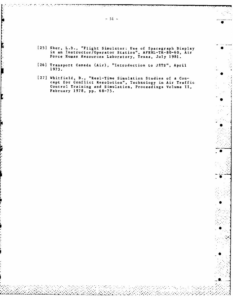
-51
[251 Sher, L.D., "Flight Simulator: Use of Spacegraph Display Sin an Instructor/Operator Station", AFHRL-TR-80-60, AirForce Human Resources Laboratory, Texas, July 1981.
[26] Transport Canada (Air), "Introduction to JETS", April1973.
[27] Whitfield, D., "Real-Time Simulation Studies of a Con-cept for Conflict Resolution", Technology in Air Traffic .
Control Training and Simulation, Proceedings Volume II,February 1978, pp. 68-75.
0
I.
. . . .-.
.:-.
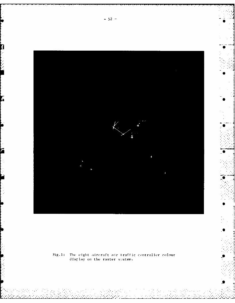
-52-
IsI
Fig. 1: The eight aircraft air traffic controller colourdfsr lay on the raster systemv.
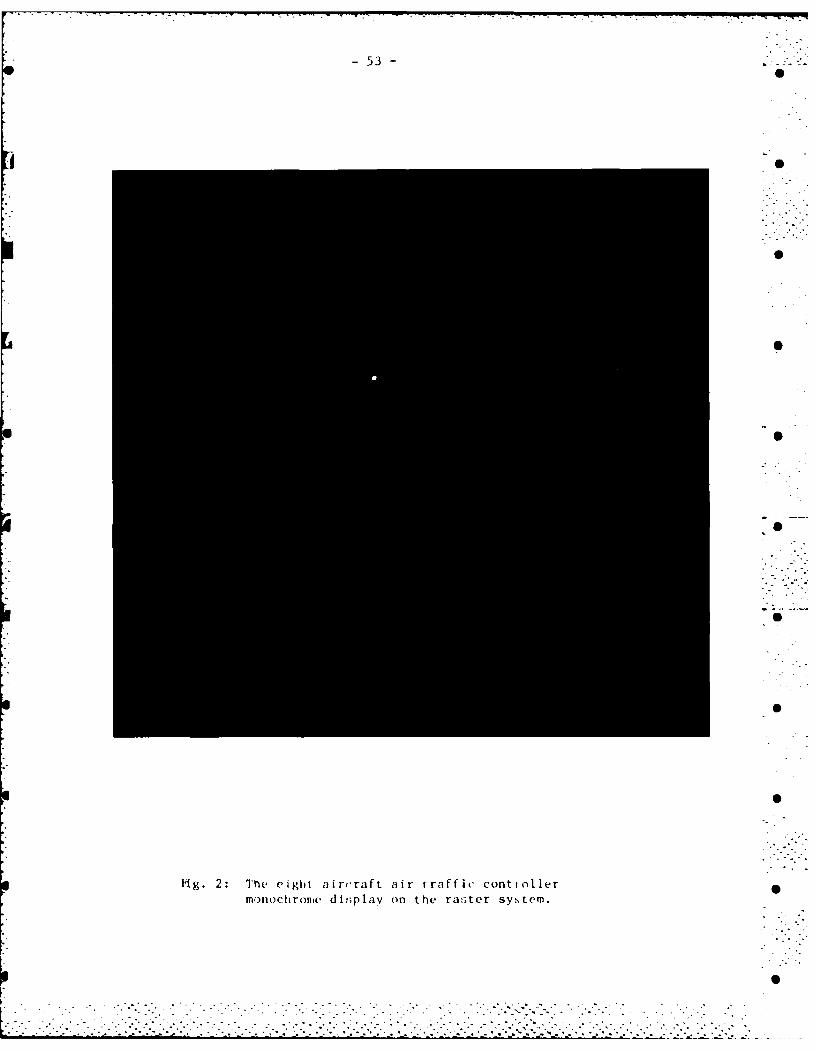
-53-
0
M g. 2: Thte eight aircraft air t raff ic conti olermnochromec dis~p lav on the ra!3ter system.
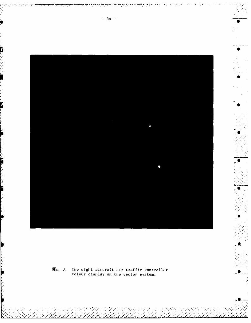
* - ..-. -. . - -
S -54- .9r
S
KF-..
p 0
S
.5
0
S
-t
ftg. 3: The eight aircraft air traffic controllercolour display on the vector system.
0~
. . . . .
A * .~ . .........- . - -......... - . . . -
..................................................
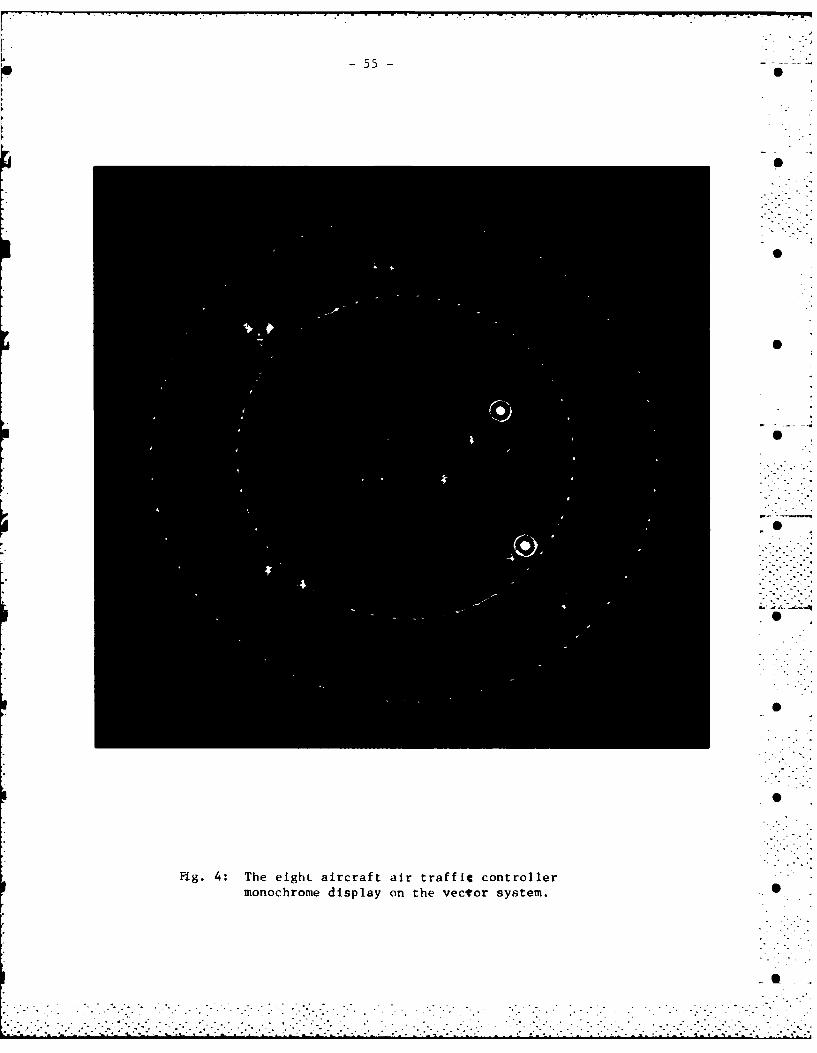
-55 0
Fig. 4: The eighL aircraft air traffic controller'-monochrome display on the vecor system.
_S . '
o S
Sm
. i ./ °. . • ... i .. . . : 2 i,- . • - ,0
"r. i ' ' ' ' ' ' - c ,, ' , o ' " " " " " - " • " - ' . ;' ' , . . ° - ," . ° - " , " ° , :

56
60
T4,- 5:The weny-ftir ircaft ir rafic cntrlle
color dspla anthe astr sytem
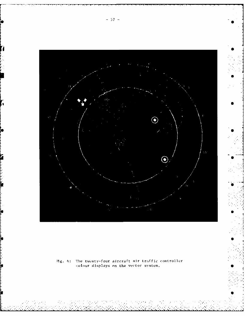
0 -57-
fig : Tetet-orarrftartafccnrle
color diplas onthe ectr sytem

-58-
P. U.
fig.7: Te scondirydispay ith niomatin o
vigh airraft
APPENDIX1
gdlib.c:THE LIBRARY OF DISPLAY ROUTINES-
L
",g~2
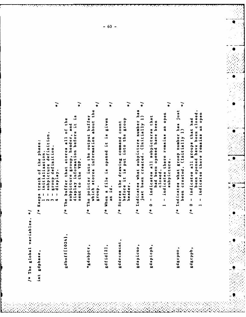
-60- ._
600
44 C0 0 a663 >4. 93- 0 w 0 03
a3 :3 03 . - 0 0 4 ~ 304" co .0 *a 0 be 4 G0 ~ co 0 0
'0 .0a a000 U- . 0 cc. 9:
0 04 0 0 s -W 03 > w0-40 4.4 m 030- 4v0 6 co.00 40 0 -4 Ai 0 'I cc003 .J3
0 0 c 041 %.,- w.0 .4 .04) 4 0 ~ 0 v.* 4. 0 44 v. 0 93- 6 0 c
0 4 0A 60 0 00 U -A -4.1 - . Q3 04 0w0A0 * 4 0).14 0 cl 0. 0 to003 92 W. 0 0
A " a 0 a 4 04 S 0 . a) =~ A4 * 0 W .- w .w0Ai C - 0 0- .00- 0 0.0 6U) r- 00 00 U)
,40.. w 444. 39 w0. .00 0. 44 to 4) -W.44 4t 0 a0 0 0. C 0A 4. 0 030 44'- A .03)C0 4 P..- .0 4 0 . 0 -A 0 .4 60 -4 a .0Va4 c 0 0 0 to
W 444.4 M 14 W 4- 4 0 0 01 0 cc * W C04
CO *4 .40 0 0 0001P0 01 m 06 ak W3 u. go 4 Q: 0 W 0uw.o-'W"*A 4 U0 4" .40 44 wk-4 0 0 -4 . 0AC 00 6064Q-
00 0op 413. -A . )0 03-4 .-1. V) U)j A VV 1k.4. mm" 03 u. 00 4.8 64.40 CA 0 v a W
CA J .0 40 (A : .. I V 03.4 cc 03o - 0 0. u 3 0030.
w .0.o.v 0 0 31 60~ 04. co0 0 0., 10 0 1 1
03 .0 .0.0 A.1014 ~ ~ ~ 3 1414 0 , .n -
A 44 - ua m
0 4a V u 4 a.
4.5 0 00, 0 . 0 . .0 . .
00 0.0 104.4 6 0 00
V0 00 -0 10Vb* b1t46 o e
4.4
-61-
4 1-
* 44
-0 I1A 0.
-44 . w 44 0 .0 .01 01 Ai c4
0 w -4 0-ca r- 0 K1 0 046
0 a 4 .0 -N1 v900 *K (A 0. 4
0 a 14
o. K 4 W3a*0 0 'K0410
14 3 -A C14
-4'0 41 VK 41 01ww c 14 0 41c 4 0 0 3 04 0 0
U ~ :3 :3- 4 41 44 41co c 1 0 14 K) .
004 000 4 r 0 %a 0 11 1404WW0 .0 44 -4 W @3 K4
44 co w4 .0 0- .O0 K* U c 0 oc
OW4 0. to 0 .41CIV I4 1= -,4A- ~
w 60 0 44 1 1444 44~4. 41 41 -4 D.30
0 4 014 K0 N 14 4 '414. W4Ho1 14I- -A K. Q1 00 14 441 14014~~0 31- K4 14 * 3 M 3c I-'
00 ~ 141 4 K 014 1.,1 * -4 --44614444 0- 4 414 @3 04 144 344 $4
0440 0 K0 14. A *0 @ .0 0aU00 ... 14 K@ . 1 4414 1
:1 *~00 -,4 K 4 ".01'04 1411
V.J @3 44 -4 1W 444 C4 W1 44t"- ..O@3-K - 0 AiW.0 41. 0
K 14 *~1
0
cd 0
- -
19 4' 41' -A -
-41 (A -4'J -
4' w 44'c
4'~4 0 4 .
4'W 4 .4 *, 468 .,1 60 0 .w
-* 1- 4' 0 * 4*
4' 0.04' 14 0 0W'OW4 .4 vd 4-40' 04 4' 921 41 a
4': 3 . 4'o 0 - V-
4'0 ... 4' 4 (a -4 0 $34'o V w' 4'4@3 4 0
44' as*- .0 4'1N4' W. it Go c 0 cc 0-4
4' wW en 1.4 -
to 4j W~ 0' C1 4. 000
4'~ 0 > 4'c) .4 n404' * 4' ' 0.
4' 4. .0 bo1 4 CO 0 '
4'~~c 04 H0U c!@ 4i 1.Vol W. @3 0 4 -5 -4
4' 0.~. 4' Ai 0 00 W
G4' J 04 0j '' 14 4' 1.- (Uu 4141 ., @3 *-4 41U 0 cc 3 .,4
4'% V0 '- --000 44 .. 4 ko . M.4'41 A 4 00 4' 93 N4W) u ow4' 0 *U~ >4'A u
0' 0. 0 1. 0' 0 m 444' - ~ I~iH d 4' .- 40
4'1 V 0co Ai '4.04'~~~4 go1 to-H ~ . '@3 -
4 o @3I -9o-'4 0 E" -.4' 0 *- 0 '-'- 4' -.4 4.4' 0. @31~4.4 4' 3 4.
-63
p6
0 *
4.4 > 04 0
-A -09 U Hd
CC 'O 04 44 0d 0.4 4a b
0 w t 1 .&J 44 C. 004444 0 0 0 00 U
0.% 0%0 0 W0 4 0k0I0 ta. m FA w. 46 )4 C6 .4 -
w0k1. 0 ' 4 0 4J V a g3 - 06 .0 0 A C 4
44 44 u ca Ud41 cc -. 0 4 1' -14 44 1 44.1 4)
4400 4. 4J4 '. 0 -' 004 4 % - K ~ 0 ~ 00M '01
1 k0 *. 00 .- 0 l 01 4 44 4.40 u
N 1 ( A. O -A. . ~-4 W~ A A -4 4
41= -0 W' -0 M.44 ' 4 ) k '44 0 co44 01 m4.~ m V'4' -,4 0444.'' '00 0.4 U) 0 4. .4 " ) -
00.4 C - 44 - *4 .Ai. 04 0 4 4 40.4444.44 a 46 4go .,4 '0 4 .,14.
---- +1 00 fi0scc 0 v v 00
.,I k*' O- 0 4 46 44CO0444.44 444 .,
4.4
U U -,4'-4 -,4''
. .. . . . . . -. ..
-64- '
00
V..
0
a S
-A
+ + + >" "-
-4 -4 r >. -
1.ie
0. V -> r.
-' 0 H4 W , 0,.*€ J M .
-4 -4 .
% . a. C '...
o. . . .
'0 4)- - :3 G =' --m0 0a u+ -4 0 - 4 00
04 -. 4. C) N .1 * ) Cl ca -4
u 9 1GD 14 VOw - 0 U 44
H -- -4 A g3.:- -- 4.4 w., A FA 4- 4 -
-.
0. C14 0G 0f 4.4 0- -1 0.4 5,- 4- - 00 0C M~.Q -.41 WD W.a .0
-E 04N0 0s'J 0 D aw w ~~ 0 WD -4 - -1GD-- bo boba 0 D- -j 00 0 4
*a w W..4 Wa U-t U .--4 444 -4 1-4 03 V0cc to ito~i 1-o- co 0 u4-'-m 0
GD.-0 14 '4J'' GD40 ~ II 44UB~~Q ca11 -A 4ji4ia )a 4.
GD-w~ 44~ G-'4 D4-44-4~~~~ ~ L GV1i1 DN ~ .e14 0-.i 0-~~~QJGD~~0 GD0. GDD' o4'* f
.. 4 CNC. U0~ '..' 0GD WO -0(A
0000 00000 00GD 0 0. -4~~~~4
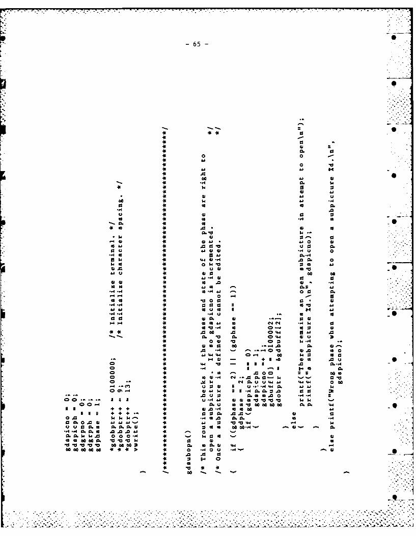
-65-
00
46 0.
4614641
C6 V~ 64
0 Aj0 0u .41 0
0 46 .4
44 01 0w g 46 4 4*
41 u 0 be 00
0, 060 0-4 06
cc0 co v 01 0a
. 1 to u1 0 4 4
9 1 46 CL4 * ) 4.0a a 40 1 0 W 0a
00 4 *101 -A0 0oCo 3*.4 46. Q4 A11..4 440 m00 Q04
044 0 41 V0 41 02--A. 46 041a
4J1 44 01 4 00 -4 6 : 0461a.40 0 = aI+Nt )( .0u
010 46 0 .A P.MNN N6 ccO
46A 00 - .-
00 46 $40 CL U4 A 4 064.4 6 000 w N 'I i i 1
4; 46 w0 4 01 0
45 0. Co FA .04 0 010
A4to041 ' o140
06 .0$4W 00 0.0. *. , 0.
46 1 9 1: A o to4 130 00- ' M10 0
46O. W4.44 00 00 000(A 1-401 M -0 VI~ 00 FAu
O000,1 (A *0 000 x: m o oW
46 Ao o 01 0. > .0 0 *,4 0 U -
00.-.-.- ~ ~ ~ i V AA 6u.4 100UUU .100.- 46 .0 00'010000000 .0. .40
N, +4 + 4601.0.4 0 00 4
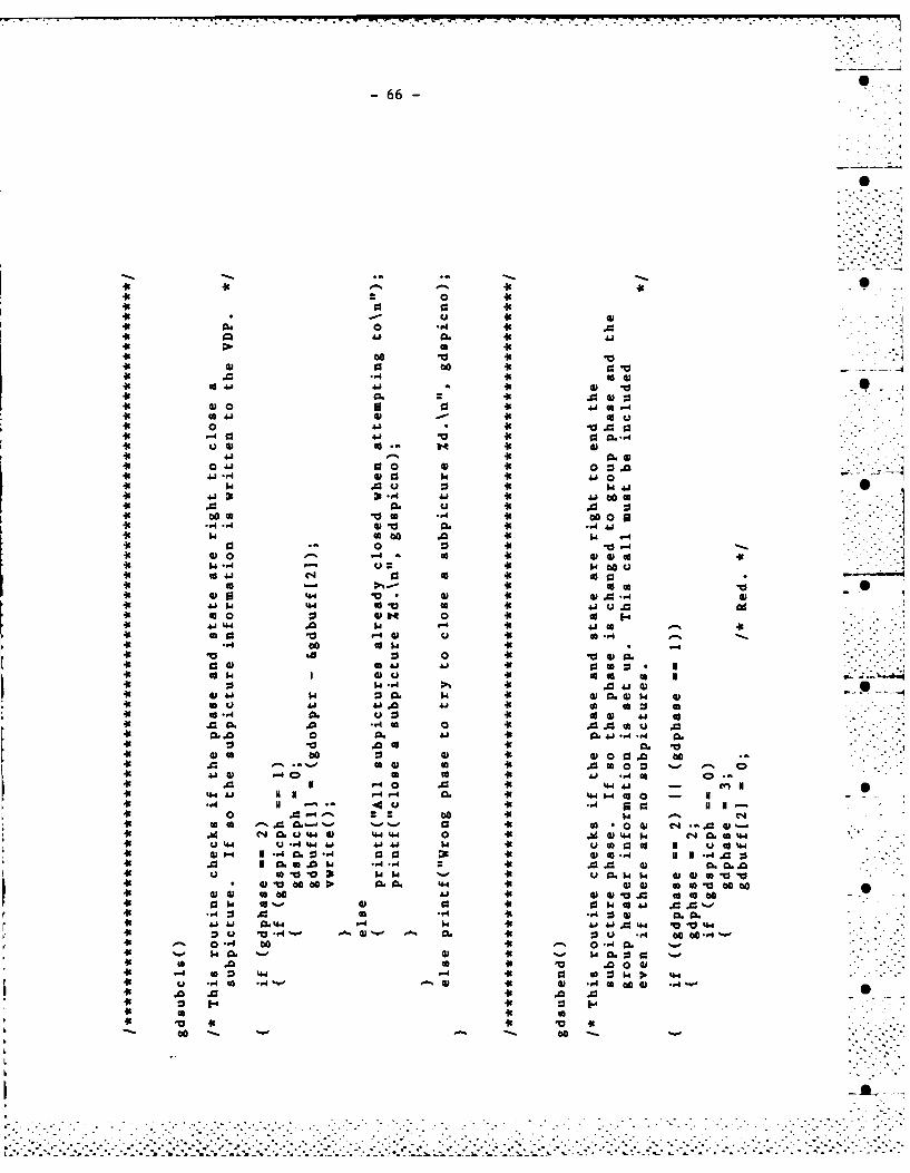
-66-
00 V V
0 a 00 av
vi 0 44
-4 CO m44
440 41 0 0 C4 044 OJ -41 0
* ~~410 31 4.I1~
K 0 0. Do p0
w 0.1 00 41 u40 .
4CoW CIA "4 cc4c C3~44 *044. 10 0. 4441 0 C A 41 u. -
44 0 0 0 4 -
444 -4:4 *40
44m. 0 r4 00-
* -4 CO$44
%a 00
441
40 41 ad.1 *~
cc4 v .0 44 44 .0 -.4%4 V. 44 4 0 0
44 4 .4 C:, to to AA4 0 .044 00 44 L4 "A4 N 1 -4..- 4 CL 44 H 0 01 c.
W4 4 C6 0u 44 41 44 44 0 44.41 44 0 C4 CL(A44
U 44 U -4"4 00 44Aj w 4 0 4 N.U CO 4
I CL 0 0 r4 9 atW 44 U0.W 14 00*~~ ~ ~ *0 410OC .0 44 14 o a
to 44 w .0) to1044 604 cc P. 44 (U4 0.a0a. 0
* 0 44 00 40 41 W 44 0 ogob
*~. -044.
Ai 4.4 1 44 44 .0 44404v0 0 u 0. 00 u - o0-
.6 0 IA a.. .. .
a . 44 -. . . . . . . z w p. . -
. . . . . . . .. . . . . . . . . . . . . . . . . . . . . . . . . . . . . .
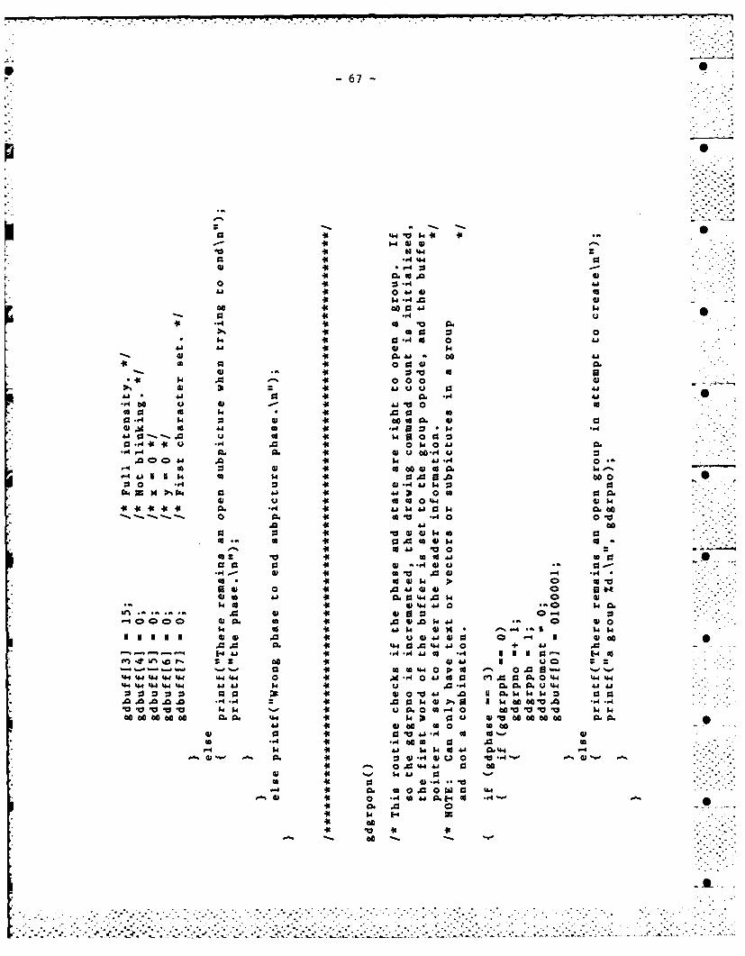
0 -67-
p 0
a 0 0a 41 CO 0DG
*0 41 *- 00 a0. v.0 .
4.1 4 0 1 0
00 41 9043 1.0
.1 a 14 4 -A'H '-44 0 60A 0.do 00 : P
kD 44 04 o 004.410 rf 41 0 W4 0
HGDA 41 31 0 coU l
41 41 0. 400 G
0~~ H K.
vs 41 "a 0ua.-4V4 CA I-4 A4 4J 0o.$
0. 0.A 41 G U dU C -I..I. .fa04. A0 41 H) -4 -.4go Go $4 GD of 0V400
41 44 41 4J 0 00.mMD U 41 000. D
qu 0. 41 0' a -40.A A1 44 CS004A0+ 4
4 -. 41 CODG H aAa 4C0.- m 0 41 Ai -Z 2
41 0 44 '0P,0o4- 44d4 4 & 4 0i .4 0 41 50 03 C 04 44
4-4 444 4 4 41 GD u * w .0 a- % 0 4 14.4- GD 41 A'a .04 1 W '-4 c
A* 41 4 41 00%0 16 0WCi, V4wk 0. 0cA1. 0 GD VVH8D 06 a mOw 41 64 1.4 a ')Vb 40 0 aa.
A G 41 to a 0 tob. i e o 41 0 0 41 A A4 .1 co 1*%-
Hj 0 41 0.I44~M MII 4)G -A 41 r-) 0 -0 -i I H0
.0~~ ~.0 41.44.4I+ ) A.- ~~~-.-.-.-~9 4D -.*' 4.1 - - 5
'-.---- -4- m a1 0 0 0 N' a 44U- .-
00 -A FAO 4 AW I- toHS -A
HH ~ ~ ~ ~ 41 00.I 0 0a' H
* -4 41 w 1-400H 41 .4 1 H04J 0.4.
GD '% 0. 41a41.4 D~0 'a.4 %vD
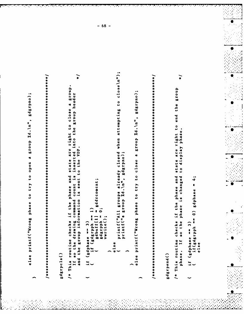
0 w ~
W 0 0
10 0 60
00 0. 6 0
K 0 C,6
46 ~ 0 04 04
0 w V 0 -4K
8k# Do 44 m0K'K 60 0 8).,4
80 K0 -4 ..-o K-0 4.1 W cc
C6 AK S30 00 V 4
41 93 .04 91 44w co4 U cc 46 co
H 49 (a0 a6 toco 04 co 0 co
0 u O. 0 4 .
FAo go *.4 be aK
1 4.go 60 'm 44k 00 4m' 4'
0 0K 4444 w.40 a) NK404 'K 6.4 44 U4 0 K U0. 3K C64 Z0 14 -A 40
co $44 b80 $0 ~ ~ $ 6K V0 v 0 K*1~*
44 v 0'44 41V64*o . C6 4.4 'K04 *1'K U 0 o 4) 44 FA V
K44 be cc0 %-K 0 1- cI041.' ' 440 U to ~ ., =,K a44.
w4 41 6.0. U4 A* CL'6 44
'K00 0 0~ 'K to'4 Q2 $. (a %0 .4 'K ..
W4' 440' k 44 FA 44 '6 'K 0U'-880 80 6 'K.044 8
U ~ ~~~~~ AK4U4 - ~ d U' 4
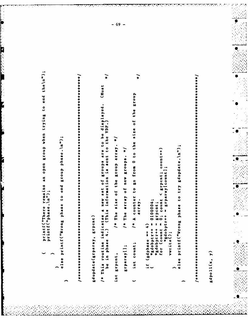
.-A
-% -S OA-%
A~ 46 4
w0 461 040 al 0o 49
o0 46 44 46
60 46 0 01 460 0 0
l is 4-4 460.
46 00 4944 4646 6' 0 a)6
a. Q6 411 01 46 -46 4 46 a
101 46 01 .4 CD u601 In .1 4) 46 o D C
A A %4 A 46 46- W.
0 a6 4.1 $ be493 . 46 09 4 1 N. 1 46
A0 41 +6 +1. A0 A40 0 4614 4+ + 0 4
r4 0j 460 0 aa * 460. 0. 4 6 0pt 0. 02 0 0 4414
1 46 0) (A EU 00.~ ~~~~~ 0. 460 4 0- '1
m 46 0 00 444.0 0 440~~' *0 *6 440 01 0> U
46 0'. a 0I 0 .)405 41 46 4.1 4.14''
46~4 01- V443: 04 011 0 04
010~~ ~ A6 b44 01 0 0'.b41. 41
.. .6 .A . A .. . ... . .461-40 46 .5 01-4 -' 1 000 4 L
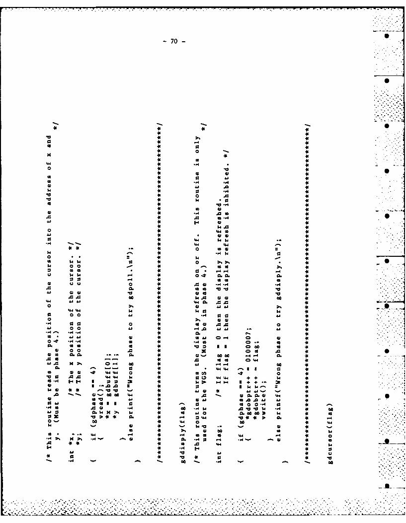
-70 -
.10
A 10
0 is leis 0 w w
0s 0 -co
o .-4 *-i
is0 10 Vi"* is .. 4 to.
41 is %w.0i
44 4is 04 *-4 $*0 is A0 40
is0 0 4s, is .4 is
is 0 41 4is i a i. I .- .
'A is W.. .06 is -1
.0 .0 6 . isDao cis 14. ccs
. o is A4 isc 441 i * 4 4 b
44 is 41 1. is0- A .As 44.4 4 4.4 +is
isis 4s 0 4j -i
0. is 4 41. a AisAj a60 to). a is 0 0 -k i(A. 00 -A is 04 is
0 b6*i . 4 i.4iM 1.4. H .%-4 is 4 0 .0 a. is6 3
.0 0. is 66 m~1i41o 444 is 44 i
0~~~ ~ b' s4 451i.'A4 414 is 10 444 i
0 00 1 is-4 0041-i
00 0 s 04 .0. 0 i
41 0041 is-.4.0 4141AIL..i
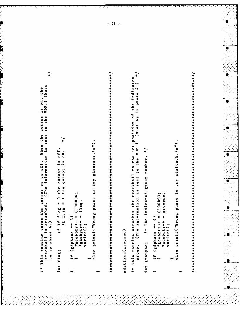
-71- 4
I.e
0 0
0 A10
41
:1 410.4
@16 1 U 41
41 .- 4'-p 01 0.
... 41 'A Ai
0 -. 0 41 0w* 01 00 V
0.0 A41 .0 0101 Hd 41
Q1 *.4 041
N41 0 o. .,4 ~ 410d 41 6,0 to41.4 a a 0 -.0 ce co4W 0 41C o - -Jgo 41 44a1 0 41
00 U 4W vi -GD. 4 4 41 g G0 . 0 4$04 '04 14 N + +1 li - 41 H- N+
to 4 Ai 41 co 410 ) 00 44. 01 .4 * 00 00 41 ca0 &j 4
-4 4 0O 0 04 41 O 44 00 410 10 w A411 w r
co 00 C. 00 00 411 0 o204 10d *1 * P. a. 0. 41
0 M0 41 0ob 0 m416u 4 -U %.4 41 1-1 w 0. 41.
Isa .0.0041 0 41U'. 41 ti tD u0 a410
., 4j -4-r 41 .. 4 00 w0 .,IU4 it 00 1... 0 : 04
.0 . .1 .. d .~ 0 0 .0 ..
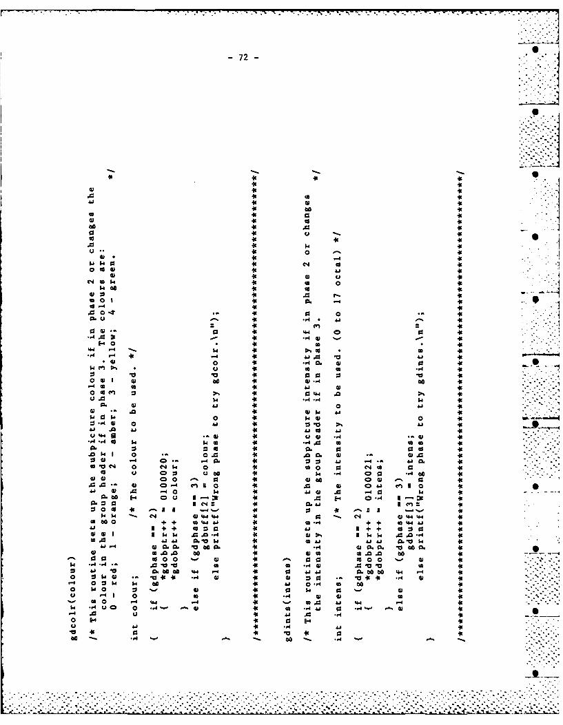
-72-
000
'K I.~ IcI93I0.14 K" 0 C14
w 00' 1'
a0 1 K. -'
A- -,4 4)E-04 0K0 a'
0 4 w IK*'
0. co 1.n 'K44 6'-I -' 'K ~-4 A 10 ' 1'
0 41*.4. 010'411 'K 0Z a 01
64 K 41 0 4K-A0 6 w u' wK0. .,4 '.K
. 0 44 w Kc 0 C1 'K41 CD .0 K 00.. 41
Q a0I 0 'K m.0 0o41 00 414 40 A1'
U4. 0 *- 'K 1W *.4 1'm.4. 4 I.. 'K4 E- 6 6 -
.041 + + 0 . 'K 4 .1 1.0+ 'CK4 4+0 +4 0. 0. +K +1 co 41 9:
601C"4 0 C'1. w .K60 0 C4 0'0 w. ~' ;.% *.4 0 0W00
. .' 01 041 10 'K 41 A1 041 w~0'
41 .. 60 FA. K 11 . .0.0 1. '
41 .00 3-0 44 - 4 'K .0 3- 0 .4 3C:01 4i 'K041 C0 DoK4
0 0 'K 413 41 01 'K 4)1-' ''1.1. 160.4' 0 to 4 01.4.4
6 . 4 11 cl01 ~ ' 4 4 4 . 1 4'
0 1 .0 Ai0.' . 5 0 0 1 0 .'0 6.0. 06' 16600 0'

p -73-
4t4
C144
44 4
m. 44 0 4
0 440 .00 4 a4 41 4
0, 44 00.
-W 4) -,4 C0 44 -A.-
*04 a. 4.4"
00. 41( 14 .. 4
041 44 1 0
41. ca 0 44 4 J 41co 0 44 4
to. 0 44 U .cc0 w4 0. 00
. a -4 444 a1 0 .0 .0440 0 o .0a 0 0c
.0~- cc 0 Q4 0 en 04 00a - A e
.4 " 44- 4W-A 0 f 4.0. -W 4A 0 44 0. H1 0 cc
N1. I4t .0 l4 0 444
40 0 44. 44 0s w 1+0 + CO44O 0 .0 000.
4.41 14 u. +4 +.E cc 000.0w 44 A. .4*
'4 0 m 00 a. 040 0 ooC6120.0 44 b 060 0 , c 0 0.0 0
0 44 001%.4 l c0 66 00
b4 0 4 0 0- 0c 44 w bo t %0, 0 044 41.40 .
0444 0o 41 40 'A 'A 0
6. 4.4 44 W 4144-
41 -r *4 44 H H4 .0 .0 -4
ac 40
0~~~.. .0 .00 .4 0. 0 . 0
-74-
0
I" -A 'K.4
49 co wK *1 0
'K .~00 K0 4
00 00 'A
'K 4.~'K0 41'
'K 4) 'K -4 0
'1K 4 0 44
wK ud 'K 0
'K .~.0 'Kco.
CA w 'K al4 4_ 'o 0 0 . 'K 0. 0 Q h4 0 o $- ' .0 Q wK 0 090 'KcA 0 'K -4I 0
41' cc 60 K40 .0
44 4K 434 434 44 K44 '4 41. to + +K 'A 0 01
0 'K 04 *.' 0 K- .
K0 0 NK w43 0 44Iol 'K 0.1 w0 0c'60 0'' 0. vK A. *-1
0F: 0' A .0 b '. P.K 0) u .
'K Aj i 4m 0 'K 4 .go 0.-0A 4) we4 C "v0 wK ,43 M
4.11 930 'K00 bO OA 4 'K Id A4. A-4 'K 10 49 .~4 3 'Kit O 0~ K4a 3' 4 4 0 o
'.K co 44 b '. 4.'K0 0 .0
'K '- 0 to: 'K- 14 o
'K0 1 44. 001 'K4 4O
go 43 0 C occ 'K E43'K K14 41 4
tic (30 0 -404 K . 0 .
-75 -
'A '
.0 p
.,1 -1 - -4 1 1cc . 1 41 '
0 030
41 0 b'o
u. 10 0. 0'
.4 01 cn 1 4
41 o0.. (A 41+ K4
1.4 41 410404. 0
o r W3- -4 N Kw'c ) 40 to K o
.,1 - 0~ Ko 0 0
E- E..4 'Kc i4J +4Q ' w . 0 w'K 0 Wb
*0 ).44 u. 1-. " a - U 'C 4 .'U.l en a 41 'K 4 C 9
-4 4+ 0 m AI ... M. u w. '0J N1 C 4J u 0 0 -4 m m- ) a
90 6.41o 41 +400 u Go 0 s -41N'Cu.. di 4 Va 0 41 41 D00A .0 '
+10 . .141 0...- 0 0 c .. 41 Kw~ CO a. V' W . 0 -0 M K~ -A -4
M.4 ' to -4 1.4 *0 'OK.0 .0 0 0~ 60 + 0 441+ 0
0 1.4 H' -A 'A 04 '~
'-4 '0 -A 00. 44N A I''
.,1 41'O4 V 01 'O K0r wto I 14 4 '1 0 1 41 4 04'
41 4 3 . 140'K 0 11K 0 44'+3 44 AU 00 UG .1
I~l*40.0 041 0'- 1.41.-40it
-76-
0
$4 ."0
-W(A0 0l C I0 3-
14 1 0 0 to V>41 0 -4 41 -441 C
u. 0 co -0 C0 -~
41 0 j.I-3 CA CO- 0
1. . 0 4V0 " 44
W V1 0 cc*- 4.0 ccw 0 -U - -4 .0 440 . ca 040. ccC.
CA -. CA U 4110 0
to 4C010 0441 0 * 0 0 r *-A -.4 41M
> - 14 Q. 0 -4 >-.W 0 0 00
r44 M(- 0 4j 1 41 41)4
0 4.4 :314
0.> 40-A *4j a 4) 4.4 ;0
-A. 0 . O9 10. (AC
w1 *..4 0l. 0-4 44 01. u 4 Q
U4 44A 0 U)0 o 0 1-4I-0 4.0 1.4- .1 I
(A. ;N(9 c.4 o .0 *0FA-0 N 10 a
0 410 00 C-0 E-1 + 4 +ca it A 0 C!~ 004
(A. 41 N u 14 410 .4 4) 41 aC ". 0.1
0a 0 4 ~ .0 +4 + 0004CA~~~ It u4 .00C O. .0 0
41~~c w. 0-. 644. 0~. C'0.U14 4 I 1.D *-- 0 -44 4.1 41.VIU+
m 0 4) Kt 41 06I 00. V. 1.i U100 a 414 N .0 ~ Wf e0~0 .
3 01 w0c 0 .0 U0 m+ A 0toA A - 4)I- 043 4 40 b1 -4 A.0 0
A 0 0. 41 Ai -A 1. to ~ -0 . AM 0 s.. C0 411 4.0.0 1.0AC4
4 O Ai 1 40 ~ co .* 0 43 414FA00 . ... 44 A .. 4V 41%. m 01 to.41
u -0 U x 0. 040
* 0~~~~ 4.0 , N 41 0 .4 C0'-
* ~- 4 41' .
* .0 FA ~.4 .1C
-77-
419' 91
fa t 0 0
41u 1. '
4-1
41 w di Geq N' Q 409 4 cl 4
cc 0. 0a
A1 10 $4 0
Co w40 Ga 0
ts 0 c0
0 41 Ga *-v0 41 m.d 0 .4 cl
;0% &4O w 4 41 coco 41 .0 0 54
U4 4 41 aa.. r4 u igomGaN- 49 b .- 1. 4a 00 '41 06
01 va Do 0 u0 V0a a . 0 C..I
X1 01 N4 M0. 4 , 4WA+ 41,O- 03 w hi M 4
-' *- 4 41 41 Ae 0 'o U 0G G:
~~41 0 .0 uW $4AV.t -14 00 4114D
u 0 0 0 41 Nd . aI1
0 c 4j4j -A 44 Ga4 r.- L 0 .di
4) 004 41 dN 0 A.0. 0W. -4 it4 ti VGVa. S 0 -
-4 A-4 $44 ( 41 w aida49 ~ 0 ui 41 4 Sw41104 41 M. 92 %D 0 01. +
490 Vi- aGa. g
1.i Aid - 44 AJ w0W100. 0- 41 H0 Ai AjV9'0U w.0 41 G o0 0 -.
004 41 4ai1. 0* ~ ~ ~ ~ ~ c AU V4aai 04 11 4 1 0 .
di 1 AU -.4 41 O 6a .0 . 0-
U~~A 41 ca- 09' ~Udi~-Ga~a4-V 00.- .04 i* 4 4 1 ~ dd
-78-
ca 0
41O w1441 4 4
w as
41a 0 4 4
-441 0 .0 4FA *..4 'a 0 S:9
41 -W 44 CC ccd A4o .0 a . 'a 0)
t1 08 S0 0
9 3-441 .0 a) 0.
01 0A .0 .0 .0wu41 ") 0 '
m 41 w 44av 41 04 0 .
'a 41 w n a) (A- .0 w .0+ 0 41 * S~0 0 $ 30V
N 4. w.. 0k~ 0 0 W+440 41. Wo Q co u0 0 +
41 0 coU 0.0.0 4 cc to + CD cc u
-0 4*40 -W 0 41 .4 Co m 0co 0 0 w1 .0 40 Nl4
0 41 - a -W ): 0.d 41 4)0 + 41 .40 .0NW k) :3 '1
W4 41 ad4 S*4. 0 1 0 m1+ a 41 - X 4-4 .4 1b 0 . a0
0a 41. -W 0j . A 4 + .00+01 00 0S~ a' 000E- -
W c oa 0n 41 0a Va~ 9:0 0O 0.+Vk 41V 00 to q ON .+0 b 0 'a 41 4 .0m %4.' cn 0
0o 4 .W 0 41W k O 'aA 'CA4 N0 N. 41 .000 0 *-. Vj 0 at
10. .,4 $4 41 V C) Q .. a40 10 0 V1 V. Do .0 19 +0 00 5
-40 0*fl0 4 04 Va)' b. 0 w0 0wnan 0d C: to 60 ~ .0 4.0 "..
+ ~ ~ ~ l 0 . 4 a ~ -. 4e- 10.0'aM+ 1+ 4 .-4 -- .- *d . 00 -MW t&o5..''a I'aPC 0 0. *b0 1 U 0 I
5'ao.~~~~ 0-4 0o 41'04-I *W nn 0- .
0. 0 0004 -AN I' 0- . 4 U -4-M~ 0No 41 C: 00 04 5.. +0 a
0 41 ~0 -4a .0 0 0
41 - 00 b 0a 'W ~ 0 m1Sd 0 0 0-S'
79-
410 .0 4
01 0 4141 1 . 4 41
41 0 co -41
Q1 0 r4.. 41 .
41 0 co
4104 a 41 -1 u4w41 41 'ao4 -A'a
-1U4 -4 41 .4 -4
41 4)4141 CO -A 41 r4A1 4
41 . .4 4 A. 01 41
41 -A 4 41 w pit
41414 to1 d)604) 441 0 'aW -Au 41 4 41A
(A ' a * 0 A'A.4 - 41 fa . .41 w- c'-~o 0 $1 CC- 01 w
92 41 ' 44 4 41 41041 1 0. 0 04 t1C 41
M4 411U A1 u 04
01 'aA .0 .4-4 41 'a 41 .0-04w '- CL 0a w1 0 4P 4 4 44 'a4 '
be 991 .~ U0 41 .. (A4160-A *1 ~ . 4)'4 A. 4 1 41 a
41 -1 ". 'UO 'U 41 P 0 -a. E-4 Ad 1 Z *- 00 41 E4 .4
4 1 Ul 0 '4 U4-1 U -4~ 4
wa 41 .0 a
_ 0 A0 0 A0 A4 41 0 4)4o 0. 0. 0a404000 1a 0.'
41 ..-4 w O0w o w 41 "o4 -4 00 0to U CL 4 W0 C:aO Uh 40 Uo 0
41 . 4 : -2 ~ - 080 10 41 0. .4 M-
$1 0U :4 -A. 41 (a > -4 4 w 100 444 41 Q41 0 *
41 0 . JA w 41u.4 s -4 0 w 4u1 00 .00 .00404-1 0 0
41 ~~~ ~ ~ ~. .. .00 .. .U1 1 1 1 .. 4 .. . 0 .0.
800
to 4
3 46 4.4
46
0 0 0
10
4j 46 4.8 0j44 0 v46. .0.1 4
41 41 c00AAAAAw Ago *0 46 0*..4 31 0 0 0 0 4 9
0w ww 46 0 0. 00 w w w w w.*0t 4. 14 :s 0 M 4
.00 oo 0 a c 0 A 044 q) 4
a6 44 4
40
-81-
is '44 i* 0 i
* is
-W -4 0 0s1
iv 41 41is0
41 (a M s
*~ ~ 0 i
fA 0 r-4 is.0 go 0 . 0s 004
0 0 U - 0
1- $4 co0 is 0 :0 Cco 01 00 .0 a l o 5 -
go0 3- 0 cs ca
(s di Q 0 40 0 -f sis~~~ V4 -44o ~ s4
49 C -4 is1 0.L -4 E- 4 0 is w- oc -
i% a0 be a4 44 . .. -.
0s 4 01 0 I1 As 4.13
it V 4 4O m0 .. .. . .s . .is .-4 44 R . . . )
.. is '0 0 w4 wis 1%.4. .31~0 is"Q 1. -
is 00 01om m 44 0s
0s >, 01 . s0s 0. v P.- ip s 0 0 be 93 C 00 060 i 0
is . ,44 0 co 0as
0 V 0 44' W ~ 0c~i
W0 0.0 go4 0M iss
4t a 1 50 0 1 0. 0 0 . it 49
-82-
00
0.10 S
to -4 14K
r-40 -04 0
0K M,-, 0 0 dK0 .j0 r4
0 0 1* .4 04cc 'KS oo'6
's K 0 V1. ou V0 ':30 w
19 wK 104J~ -40
'K 0u 0 61 .,
'K. 1.- 4 E-4 "06))co4
V 0 c -
00 a 0K (A V U e 4.4.-'4
o~~ co -A 1.. 'KfA*45 5Ma O J a' .0 6))6 Us u
0 A ad 0 K ' 00 00 '-0 '01 W *4 10 a... . gs VK 14 g000 0 '0'0 'a0 0 'Ln V da 0 w cc.0 0 0-0 .0 .
b 0 -4 4 C0.4O ca 'K u .-4 .4 0
0. 0.001 .* l. 0 0 $40 va 0. So So. 00 A1 61 .4.'-0 to 'K 41 >~0 0 .
0. 4 0- 0 000 10 'K V. -4P Aa to to00 00 'Kc u~ M ' U ' S4P. - -
0 '- -. -. - 0 'K#4 '000V 1..'K r' -41 U M
'K 61 w w -4 g300 0 04j 'aaa'''. 'K 41 413.0.4 u 31 '
V0.0..0.0. 44.' 0 1 .,4(A SA .0.A . .0 'K a V-000 a 0 VCO 0~~o. 0 0'0K -A 0.-4k * 0.Q
* ~1 10 Va 0.00 00*aw 1.' 'K -, 'a 44 6'44 a.. 0K K K K K 0. 'K )t4 31 6 0 0o0 (A 5 0 be 00 A .A 1.1P%. 6
'a 61 *.4 0'K ' 1 . cc 'a61 0 '0 .0 4.4 r-4 K W 5444 441.W 0 03
00w -'K P 'A 0 00 o w ,
0 Do ' ' 0041 V- 00 '='
V-A--
e 0
-- , 0 0-
49 0 ca i go 04t ~ a 0 1V ;%-
+4t 0 0 +49 0 M--,10 I
41 4c *41 h~ 0
+4 4 10UW 4) Uit P 0 0 93 10
o4' w -4 0it U '4w 0)
4 -0 9.0 r4 4
*1' 4J1 u r uV
4 0)..
I P I*4 §04 c-
-84-
> .0 a
"K V
'K~ ~ 0 ''K - 01
$4 0 CDWc 0 1 4
VK41 13 00 6 4 0 g: t 4
'a 'K Qa0 0 1
03 ' o 4A o0 g
'K ow C4o .0'013u 0 DI ' 41 0 t v to0
j-. -1 12 4 0 0 A0~' 00 0a S3;%co w t u C
0 3Me 1c 1 )A -) Ai -4 -03k C0>% W w 4 WK to 410. V.
0D 0.K4 .0 0v >%0 1Ab 4 ) wC00 +- Q. to co'40
0000a 0 CD wK 41 003 00314g 4 Ai0to~t -* * 0 o'0 0
I 0 N A 0 '3 AK 93 40 A ' u 4
:It' -4 'K . '0 + +3
. .. .4J ha 'K 44 %-,a'. 0 03"03mmu d) 4 'a 'K . 0 h U . .,I
44 41' 41 -'K0* 0 to wa -0 A I0 00 .0 'K4 'a ~ j14o -4 w 1 0: 0
*.... v ' .v. ua Is %-o 10 %30, 001 1,.-.4.0.%.'~00 ac 00 b $00 0 Ai 60 cc 0 0. 0 6
:3al al a O . V 0 uK 000 'a $ '00.40' K'. W -A 93 13 400 u~ - 0 0
l00 0 3 0M a 0' 'K 0. 31 ... a 'a 003to35 0a 'K $4 0 A00 0
010lh 003ro41 0 uK 'a9aoa310410 0) 'K *- *-4,
'-' .0ha 'K '0 ~a '03m o
++++++00.0.'.~' 0 .~ 'K 0 40 ha .
-85-
.0 X w
41 04
V cc 41 4
W1 0 -Ab
41 00 0 "C -4 -(1 0c A ~ 14u
-A CO 4 g U* to-X
41 . 0AUo DIrd1 6 0 - W .i
1 V A .0 10 0 'a4
01 04. 0 :5 0 .,41 413 a) m ca"
=1 0 o0' _
go r4 . 0 . m c to+%0-01 V co 4 0-4 .00 W 'a
U .. 41 w -0 0*to 0 LI3 "01
w+ V1 0* 0. uto to a w 0IV + .0 co w 1u
0 4 41 1 4 0.W. w 0 Od140V 3 41 4 O o W .:0 0 4w00 .O
o $4c O- 41 0 3- 0 0 :5 G-N 4.4 41 01 toCJ.J .-A 0V 41 V . .~ *
a0 41 CC 4 -a.4 U u 'A
U4 0. 41 co 0 1-4-0 0. c . U0 34.o% '0 41 :5 w -W -4.W .3 )iE-4 0.l 0 0 to
0 4 i co o U 0 AJ $S..40 CC a1 0 4.o 'a 6 0'0+ -4 41 0 . 4 D o- 'ao 41 0 +01. +1 . 0. I~ 00 > W.5 W0-.' 00a
N 41 0 0 U.40 0- 0 11 9 UN). 04.1 U1 .0 6. 44 U1
41~ 41 0 .. .U .~ . V..
0 V0, 41 4 V 0-0 ;0% ON 6ww6 0.V.- **1A' 41 41 .'$ .0 .a0 090 04 ..*. *. . ..'
1. u0 41 44 00 4' 0 .0 " U 14 U0440..004 - 41 'a 44. 00 0 V - 00s 'o 41 00.j $6 c-ac w i.W4o600 0 O . Ca 0ccs~s~o U0 41 00 0. 14 41 1".-% aOSmoaI.oU
44a 41 0. -4 1.0 0 00 4*** *4*.4 ' 00 v1 0 w0 l9a '. 600. O
(A4.a '4 CL 41 4-4 A to 41 0' 04 a * s0 0 Cl 4
0. 0 -A U. u~a- -cc 0.41+41'.0 ~ a 1 0 - 00 0
% 4 + 1 0 *4 1 ,' .1 4 + 1 4 0
866
000
Cho
164
0j 4
93
-:2t
-87 -
APPENDIX 2
.: ... . .. .. . .
e.tc .t .c:
THE BASIC ROUTINE TO SIMULATE THE.".---GENERAL AREA AIR TRAFFIC CONTROLLERSCENARIO AND TO ALLOW INTERACTION -=
...-..... . . . . . . . .
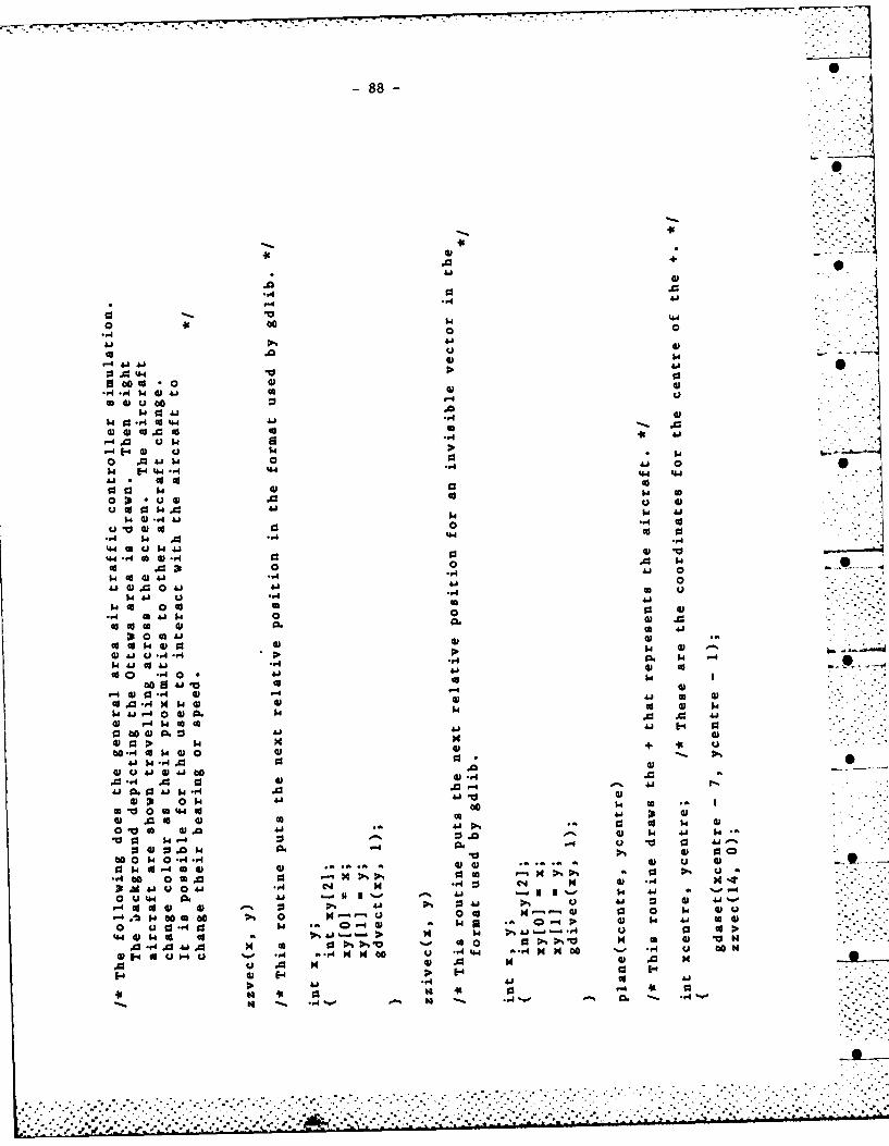
-88-
0 60
.A.50
:3 .0.0
4 4A.404J'
0 0 u b
W. C.4 41
0 .0 -W W 0w6 j.4 j.4
41 1
.444 44
0 31 091 0 $4 A04
W1400 0 U .
'-40 H 5.44 ca 4.
44 1 U14o4 .042 .0 0 -A w
cc 4 3t "4 '0
0 0 0~ "1 .0 .,0
w *41. 0 41U w 411
w9. co 0 cc4-4 CO 0 4J 1.4 0. 4
".44
go -,4*. 0 0j 41
0 0 0 -W .0 to
co.041 .-A4 m4 4.4
w 0
14.4 U A. g34U
. 14 A44 0 0 4
O 41 0. 0. " - .0
CO' 0 CAJ 44 0
0 V g 0 0 41 41 41 c
00 40 $4 09 -A4 -. V00 Na 4 0 4.l4 .... 4.4 41
31 A 41 o 4 -4 4 -4:34(
u - w o0 . 4141 a-I ONgo to 0 4 4 41 41 U 4
w 6.0 Go 0 Hpl 0 0 co 0
01 .- HU .3
-, 1 w A 4)
4-4 1 . '4 4.is46 4 4.1 a4 0o>
00.-40H40 41 44 5
41 414 .1
4.40.04:0.9
410 .01 -1 U 41~
OWU 410 .4.*4.~%0 $H4
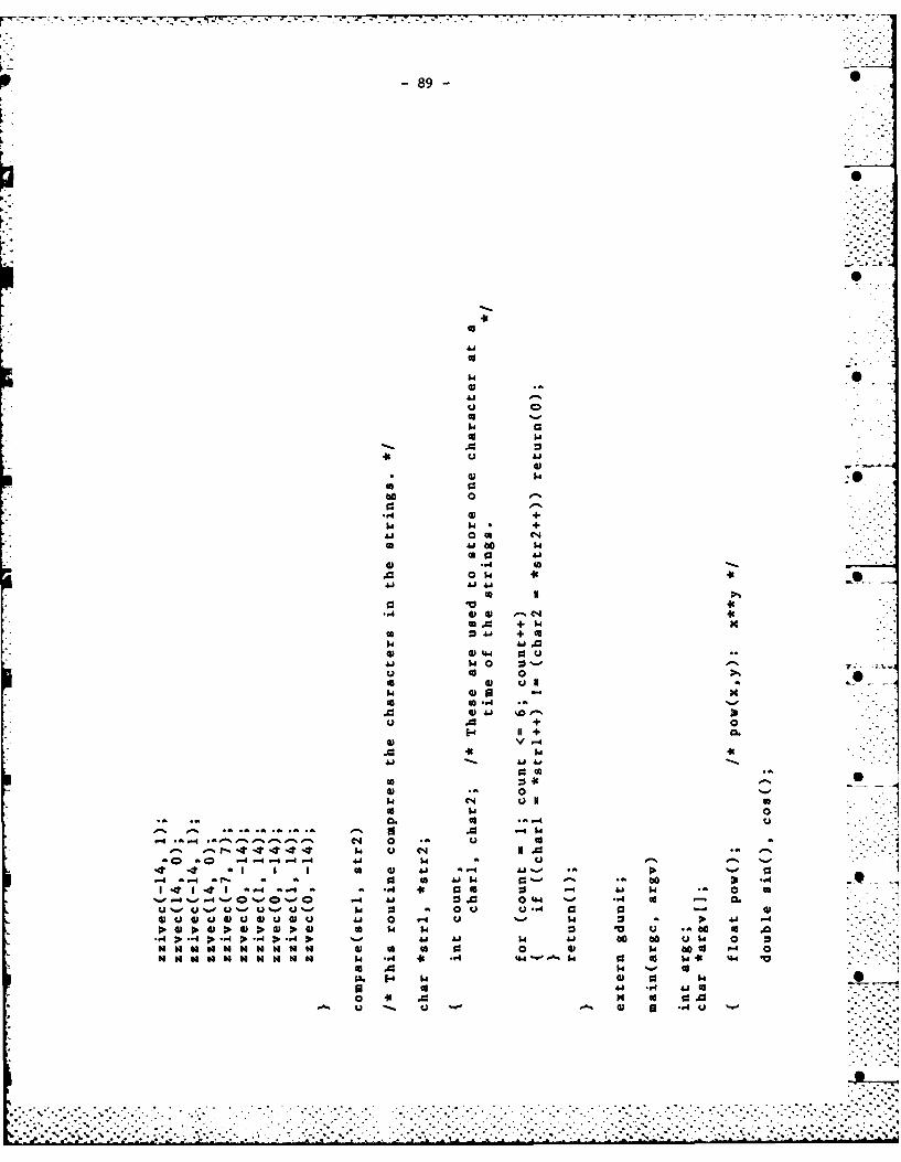
89-
00
600
0 $
+.w+
144
41 w 0
Iwo5
E14 +0
0 1-sFA
* *
00
144 140
0. 04 co C0 u.c 93 934
(Du41 0 4 0 ;o 41-
-A 0> 4'4 4'A 1 D fo 1
-. 4 00G goC 4 0w. +04 $0 c
$4 0cc 41 U.K 41t
900
go -
w 0 4.h * 0 :3 w $4
0 .- 0. 41 .M )- 41 -6 -4 :3I 0 4
0. a. E-4 04 P%1
* 0 .0.- r44 *2 >441
92 0 1 -W 0 LAM 4.4o0 0.1 0 60
41 0 .0 V o 1.4CA0 0. *.4144 .-1
- 60 w . ro 4o 0 0 c d10 V41 0 41 40 -
- ~0 0 .4 >t cc a14 4140 0 0to0a0 044 0 00 0=. 4 .0 cc .00C4 .0 60 - 0 c 0
ccU 4 0 .0 0.0 440 w .goQ wc
0 1 . 41 0 6 440 0. 10 04 r. w
0. 44 W4 ., 41 .0 .0. -41 u. m0 00 *.40 00
0o 0a 41 4o 00 4.4 41. 14 04 41 ...4..
: 0 41 600 0 0~ 4141 0' A 04*.- -, w.D a 44 W. 60 44 -r4. 0. 1 44 N
m0 x a 0 0 -A.w4 60 .0 41a410 0 00 00
*l - -,4 41 0cc 0 IV 41 $4 (a41 $4. V 0 (A4. 04.a41 -$444 1 44 0A 140W 4-A.0 0 a 044 04 144. 4.0
$40 0 4. 0 00 1 -- 14 .04 1 0 4 41
-. 4 0 4 0 4 . $ 4 . 0 g.o4 6. 41 A
m44 .0 0 41 14-4 -. 4 cc. 0 0. A*4- 0 A -A 44 '15 01- 0 V 41 j0j 4.4(A
0 4. -4 Cs4 04 -.4 64o .0. :1 6cc $U 40
414 641 6 co s *0 41 - 0 1.0 0 0 w 1.4 0 C
.04V 44 CO '0 a 14 -W4.0 .~1. 0 w40 -AW a.w4. 5 g 0 41 cc c 41 ca 04 1 -A 0a 1 4 0 w0 . V4
0 00 6 0 w. 0 40 0 0.0 4wo 41 .- 4 041
4 0 0 00 6 w0 U w-. w144. -A 4 410 1.4 64 - 0 4
04. .a w4 co 0 4 041)0 -I .'4 93 0041. 10 (A4 > 6 A6 ca W -A44 4.4-4 44 - 0 .-A 4 -A1C
to 600 0 0o r4-4 - -4 0cc 6o -4 0 6 11 U cl0 0 I-1.,I 0o 0 as 0 414 0 co -4-41$4u
VA . 4 r-I 0 go (A CO A0 A0 c .0 0 .o0 % $4 cc W
-A4 4 4 1.4 I- - -4 uca -V4 A 1 r4 .0 c -.4 j C
X. 41 4 431 1 4 4 1 4a 4 4 w 4
E- go. E- 1 a. ~ - - pa E- -4 E - -
C4
V -a 1 to 41 a
a~ -a -a 00 41 ) $4 U
'0 04 00 .1 0v 0 ct
*44 0 0 . 0 1 cc 1. 60 a . 14 414 6 1 u 41 t" 0o & 0 41000 4
0 0 0 44 44 44 41 44 44 44 A4 A 0co0- -I 0 3 0 3 0 s 0 000
t"4 4-4 . -.4 - ., 4 - 4 -A .4 PI4 -4 U 44
-91-
A.% -
pa -4 *1 $4
0 go co *"4 0 w c u(A6 r6"- - 1 r- - > 4. -A
0 0 w6 A. *3 (. 0.4 cc6 9
* * 0 4) 0 0 46 40 0 go. .6 ~ ~ 0 .
go a6 130 - * 4'.4 r-4 4. 44 4)4 A 41 ., a1 w1 '0 '4
. . cc 0 0 0j44 4 0 0 0 0j '-I 0.".4~ ~ 0. .0 to1*40 - ) "4 4 0 0
41 w1 41 c-c w4 .,1 03. 9641 . :o~~~ 0 44 0. 0.0 4 ."4 41
0 o 4 o 0) .0-o 0 41 44 '~ '4 .
4) 41 5 0 0 0 00 41 41 :3 0). 'o0 41 . 0 4 4 w 0 04 '.0 0 u1 4) 0 0 0 0 41 0 w A
-4 -4 ., '4w w4. 39 99 '4. -44 ". ". 4 0 acc 0.0o 0 4 . '4. w. 0o 0. 44.4 .00.n.,
4 4 0- 0 0 44 0 41 0.4 w.4) 4 44 :5 4% :3 60 r 1 0) 4 :P% w. U 0
.0 .0 Q 0 4 14 : . . 0 44 cc0) co I.! 41 4 -4 .-4 0. 4) U i ".4 M 0 C:0 .0 $40 '1 "4-
4)w 0 u 0 C .0 c 0 0 0 a . '4.o- 4) 4.'4. 44 .1 0 ' -A ., 41 0. '4. 0 . >'0 4
0 0 0. I4 14 0 ca 41 4)4 44 0 00 c:1 o 4) -A .W 4- 4 0 044 .1, 0 V ) 0 4)4)E- '4.41C) 4) 441 "0 w- u1 .0 -4 go 0. 14.
0 0 0 ' 0 0 1 v ) U F0 co' m- 04. 4).
01 0 41 0 . 0 .1 : 4) 4. w1 4.' w 0 u 1 4- .0 C0''.~~A 0 0 0 .0 0 G2'4 '4 .0 0C2
H4 ~ 0 0 14 '4.4 0- 04 E4 H *.. H6
44 4~ '44 0 0 C ".40 416. 441 C.4 -
0 U 0 04) *14 0 '4.4 04)o '.4 be-
0% 0P ON. 0 00 ) 1 0 0 1. 4. C:4. 0- .4
1. 4 4m -0 -.. >. 0 41. -4 "4 0 0 4 o 0 w-0 ~ c 03 04 4-4 93 1 4 44 *4. 0 w0 00 41 -4 1
U U 0 04 04 4. 4. 041 Q be ~ 4's 01 41 ".4
01 &0 01 01 0j A1 0 41 4 41 0 46 0. .14
4- -4 44 ' .4 93 -4 14 43 93 - 1-1'-4 93
.. '4- - a-4~~ -4 -A. -.4 --A 44s 0 4 - -
4.4 01 A 1
-92-
Q CD 0
o o 0 0l 0 In
4 N-o --4i 0 - ~
uf 0 n 0n 0l LM 00IA
cj 44 40 Lm 0eqe e -
1.4 C*J C2%-4 it. %-, C4 Ia.
CU -4$4 J .4 UA -4 9: . 4 M .14 Q. 91 W .- 4A. *a a 0 0 *a *a *au uW 0' -A $4W-4 A W A W - A W A 14 -41
V V 101 IV 00 a 10 a0 a 0v 0VvaV"
jJW a0 0 6 0000 0 00 6 00 00 0 00 6 OU0U0000 ba 0' b
D-A153 634 A GENERAL AREA AIR TRAFFIC CONTROLLER SIMULATION USING 2COLOUR GRAPHICS(U) DEFENCE RESEARCH ESTRBLISHMENTOTTAHA (ONTARIO) B J FORD SEP 83 DREO-890
UNCLASSIFIED F/G 1/7 NL
EhmhohEohhhhEI
II..K.mmmomom
I.8.
L o11112.
MICROCOPY RESOLUTION TEST CHARTNATIONAL BUREAU OF STANDARDS- 1963-A
-93-
av
o-. % C4 o*%^ l-^ 0*-, -C o %-;: .. O
0 40 -C% i Q 0 a n 00 ino-, 0 -%
C; a C; *a; a; . .4 . a M a .*a
MI ( I - en en 4 -1-- %.4 -4e4-4 4 -4 en-4 Q.%-, NC4 -4 .4C4a 4j %., -, 41 %0%0 u Q%.o %.04%e1. %- %0u 0 "4.1 %. % -r6 4) U 0uuuUU u u 0um 1 ,0 0 0OU UUuU .w 1.WwUUUUU.-
*0 NUNUNWMO -s 11 0 14 0 '0 '0 '0 '0 40 '60 a 14 1 .4 4 11 .40 10 6000 0 60ad0
-94-
in~ go 0% **.* 0, Q * li 40 *a -in Q .* n 04 '
C4 6% V% Sf4 a W *M tn in * - %0 &n ~--o u u . u u~ 00 u uu 0 u *a%% u- uA u ~ Q. m0 uu0 u u u -.
D. 606 C o o: pP ; p; . A 6 o pP ,0 P*0.P.D.D P%00 0 .0 A :*- ' ' -E 4 A ' 0-
a4 a4 14 0 to ab a a a a a a a a a H a a N a 60 b ltlHHta a H a~ a a a a
-95-
ON fnin 6
0~~~~ ~ ~ ~ -ML D0C 4C 4e
CD - 1 N cn C4 4 ( en 4 c -4cn c en1 0
U 4 a41- *0%o 0 *& 0 1%- * i %- 14
*a *a 0 0 a 0 *a a n w a 0 D a *a :0 0f *a w a w... .fl, ....
D, to_ to a po -AP 0 0i 41 0% 00 to P. -A D. 0 0 b0i%" bH In % O-0n~0 0 4NO vo - I .~(w .4N ~1 I NVI-to 0 -0 0 * .0 w w 0 w* 0 W~* a ~
-96-'
r%. *a. r- ~ CD a D 40%w oD w a %. 4 .. oP-4 -4 -40 00r Z-4 CA. -% f n ntoa cp . Clf f A9 0%C. .a __0 4
a4 i0 I -
0.Owu 0.0.ONmO. m0 u 0 0.0.0 0. a.0Wu 6u 0.0.0 m m 0. 0u 0 u .aoo0F c6 oaa W W W 44~~ N a I.0GoP. a a 4 0 0 6 .4 b
v vU H N 0 v vN v v0 v M v vvvN N mvvv l N N1 H -000W N 00000000000MM 00000O00000MM 00000000001M NM 0
-97-*
cp.co
CD .00
0 ~ C '0 *-- *n en. ~ . 4 .4 CDkmc4u 0 0% 00 Lr0 0 -1
__C I '4 (A *.a NO .0 .3 (Yn (W 3 en * .4 - *
.4'- -- - . 4 -~ '0 .0.'0 4o 0 4 %. C4 v4 0 .00 u 0'0Am 0 0 : 5 41 u 0 IC. u' : u 0 - u %IA u 0 u 00.0w m 6 0 4u )u 0. 0. QJ wm 0. 41u ju .0.G 0 .m )u 0u 0.0.0 04 . 0.
64OI. 54 IVG ~~ d~~~ P-~J~d G~ 4) w -o4 4aq p
V0 V S'vvMN N 'US HIIVO vv NNSCU'' ' .~~aa '00 00DO000 60N N0 00 0 0 D 0 0 N00000 wNN Ca0a (AH 1 cc00 0 0
-98-
eel co
M M N
01 I Go 4 C- C4 c
1 %00 Go 0 c 4 C. 'tLn i . I .. . CD .. . . . I. 6. I MI
Cp% o-%0 40 -% -% u% .'t .- % n 0 .- (nC4 C CO) %o 0 0% C4 M 41 t
P 4 1 a a a a GoQ IC a 9 cn a -4wlI 'nM 9 -42 0 4 J
%.oCn 4 O %' Q.o f %o M -4 6%. %, 0..o 4 .o 4 - 4 41 0.%o0 44
u %. w 41 1 l Q A U 4J4J U 0 4 u 041 j cV U 6 M0 N0. %. u 4 u . 9 0 13.0. 0u a u . 0 0 u10 vw w0 0w w 0 w vw w w a po w a Nt a w
4 p .4 ; 6 60go41 0 e 4 >.14;w00 0 A ti b 4 . .4 ( 60toAj o A a > .
vmmm vvvv vvm mvvv v vv mmv vvv l 'Co00
.
-99-
m 00
4 00
C;;O OC -44D- 4c IC 0 %e %. n U%04
-- 4 04. . 4%e. - 0 1 1 1N14 Qo4 n
U U -u ~ ~ ~ ~ S u . m u009u0u0 . uuuuua 6 UC
> ~ ~ ~ ~ ~ 0 P.:0 p 0 t op AP I:-.4p 4P o c s0 . 0> 0 0 6 oP 1 .6
1 ~ ~ ~ ~ h .41 a a. 0 404 4. 41 3. 0 0 0 10111t o6 U
r -100-
in C40% eqcn 0
1 04
%- 1- -4 a 0 . 4- Q 11- 4S
.4 a %.0 u~~ .a 0 " -0 %., 4'%o%. .. o U... .u 0 u 0 w a IA *a *- 04 a a. .-.-. uu . m- u u. a u u u 0 C
'A0 Cs .. 4 : .4 >.a4> -4 P * r'0 004 aa>>D >00 4' >a 0 P . P P >>V v H N 0 H H N~ H 1 H0 HIC 4 v IC NHH P 0 C0NN0 HHN1
ao a0 0 .aaHNOI HN0 o0000HH to *a 0 H 1 H INH N
101-
600
1 0. ,--%U 0
CL~~~~~~~ ~ ~ ~ ~ ~ 0 u u % 0 .ww0 0
. .
4':?ii)
,IS
+
+I
o
- •%
.0.
'a ' -S ., ,-,, ,
0 .4 -
00 00 .% I C 0f --. 'o" 0 ":.*-.-"."
• -- I I I I IVt' -. o* "" ,,, , *' *. 4' "1 tE ,1 0 4 . J "
I . ~ .'.A-4~. S ~ 4 0.4- .U .'.- - - *OCIA ~sf0 -'- ~-00-e-' 0U ~ a ..60.041:,
6 0 .4 00"3.-':00.
o ~ 0 a ' U U~ 0000 'a a N00.. -. .. ... . - .. .. . ... ,. -. .. .. . .. ... .. . :. U .,U :. , ., ... .-.. 0 . . ., '2 : : : .. : : ., 41 -0- M -.. ..2 ..... . ..
ha64414414114114144144141a hS~ha00 0.0~ h
-102-
000
to 0
0 0
o C4
00 0
41 4 j 4
u0o
41 - A- 1 a. ..
OM -j + 0, -1 1'0' 4 MO -4 4 S0.4 o NC )Nua
W m 6 6, 0 -4Aj 6 comw(a 0 4 0 00 ss 1 1 91 0 g 0 60 92 4 -4a C . . o 9
4 104) 1 Nv 16%- 1 9 :3.0 0 4 M M 4M,- 0 0 4 0 . . - L.
u 00000 j 1 N00 0 u 0 0 * & N 0 -WQ
1006 0- .D 0 $ o0>0 0I
H o4V4 0HHV4 00v v v"N0v"
1o HU0410MH0 4 4D 0Nto ob o
-103-
N N C4
en0
CO CD V cn en S
C'4 N C4 C'.l
r-~~~~~~~~ ~ ~ ~ ~ ~ -4C 4r 4M- DC - 0%e. 4- 4Q 4a . 4 a%-o- M
%.. %-, %-0 '.,%o %,u 0 "%,-,'. 0 0 Q%0.%-
__ u 0 0uu .*a *a 0a 'm0 4. 0)uuu C4 mmw .4 4 0
> > >a > a >4 >A >*> >0 40 0 *> > a (V0 (I0 cc>>>aa6 o oub 6N- I 0 N V4 v V N~ "A " 1011 oaVVV1
40 aa aa N N m 0o '.0 00 N- N'. N .00 (4 00 IA ~ w 0 60w
-104-
0
C4 C4 C1 00
C4 LI; ~ .- C4 4 4 -
'.0 ( C; C; '.0 CD .0 '0
r-t % O0%0 W 0 F C 0 0 DCO co 9: 0n c NC0 : o t.4 M%4. .4 U 04
a 00 0uu00u w 0 u~ 0. u0 a t-
a . -0 01 011 0" 0" a1 Va V 0 V 1
'ao Do 6*0% 0 0 0 60 60 -00b 0 60 6.0 w ~ Do b .as 00 0 .. 00 *0 14 -0 0 b .to 08 b.-.
-105
000
-4 Lf Lr%%n Lnin -
Ln% W '% 4; -4-.-4
4*-.a44 - l 01 -4 U%* -n .- .
0 4 uO 0 Ua %-0 U U u (*1 0aV .a .41 u 0 u
0.11 I go Go ue u 0 o 0. 0 a.w0.4) po *a -0 a) a a) w 4) 44 w 0 a w..w
>. -A > %4n4 A >0 -4 > - ;- - af , . .> 6-014- coA 0Wuc 06V V V N N t NN 1 1 mACI 6mne' HC He " . Vu% V Iola 0 m.0
00 60 0 "H N N C taGI muw w w 0 0 00WMOb *-I 6.0a. 0.
~ 1.~a~~W ~~W W~GI~GIG~k -4 dWGAD-.
106
_- CL %. a -403 .w% -4 4 A. m . - 4 -4 C-4 4a ~ -4 .-
Im.4) 4 mn 0. m C0. .C4@ ~ 0
o U 0 d0 bo ao0a D 60 41 00 c ao Is 0 4 0 1 0 00 U aoi *vvn:v Vw4 vvv vvv v.c-Ivvvvv~~ oow cI
wwwwwwo mmo~'ww -ww
-107-
O-0
co C4In -fn C M C
0 % %0 %- "0C-* C 0 0% 00 C* (A00 o0r o0r . 0 CDinr 0 - a
4%- 1- 0..0 1 P -4 .o-w 4%~ * 4 . % 4
w 0 0ww0 0 w-
as 0 u 0 a Cg o6 v c eco 6 046 00 0 oaut oUab oa- ctV C V- v0 V 4VVVVVVVVVVVP
-108-
490
00
0
00
440 4v
o ato
.0 00
4 4 -4
- -a Iw.4 0
-4 C4 rC40
~ 0 0 0
w. ... ..4 C4C
00 ... FA 4 Z 46
M%. .54 -4 C2 0 c
k4 di -4Ne 4u%%Ci
00 0I0 ak 44 a 0 A> %;w
-109-
II 4'
41 Ae u
0 M $4
I C6 40 0 0 W-
w co w4
w0 A 0 0
4) 4.5 V .
ca001444
401 0U 4.5401a
-40.~4 00 be
e.40 0 1
001 4)4
be A 4 0 0
0411 0.6 1 04amP
ebwe 000 0 0*0
0115.4 A0 e
.c;4 4U;i ; ' 1 QC ; 0C nGGo 010 06%0 0c 00 > a0 -0 T '
A A N 44J n 4 - 1 n- wt4) 01 *. -) N
-~~~. -0"m-*V Dr-M"Nm *i o 0w00U
010 -4 U ----- ----- b-e- 4-Pot me% P. o .m0 . .0000C .mmC
@4.5 o1
00
-110
m w4 -0s
u 0 K -
60 14 $.4 *-4 a 4-1 0) 41 0 s4a w110A 44. A .440
440 014 41 as$
k 4 C. .4 0ZU 00u4 (0 44 0. o u ,0 a 0 )
41 C.. 0 0 4100 0 a00 4j 4 48.40 .0
0o 14 .0 + a.O .0 41 U 41 0 .v 0
41 ~.. .4C rl 0 " A ".1 U4 CO 41 cc4 0.
.144 3 a 414K1
0'A 41 r4 41 311 -9u C
Q.. 01 c1- 00 410 W 044 + oo 4" . U3 CL0 -tv -
.0 0 41 04 A-4 +0 -4 4m1,U 1144 31 939 00 0.
>4 0 . 0 ' 08 (Dv 141 M0%0 u 41 9aO 4 & 1 14 0 4 44 a 4.1A. *4 -A 4 0 A a1 0 U 0 000 - j-
0 a0 4) 4 tv 93 4U w a 0. Ia aA4 1r
0 4. 4 0 92 6 4 0 0 a44 to O Ko .0 w4 ' r4 0 4P
014 *'4 CL p4 41 A CL 41Ai 4)4) A. 4) 0 1 04 c 4j0 0. 0 41 244(A A .- 6 0141 r-4 041 $4 31 *A u- u14l
c-4 41 t A A 1 . -4 A 0 0) 4)4 P -4 400 41 t4 0 41 14 K U. 0.0 N 4 1
P.' t3o44 I 1" 0 4 0 0 - 03 1%4 93-r -A 41.0 0' w- 41 0. *.. 0* + IuA1u..
00 u140 0 0 w14. 6 0 to 4'% 0a a0 a.-4 -40 '- 0 41 00 d0 .4c .4-4 41 A- 0- -44
0 001.44 A- 0 146 0. .4 0.i. 414 ..1P-%44 U 41 0N 44 U 0( 06U K. 44 .
0 1.044 0 w. a 10 *4 3 ~ . 00 '4 4 1 0 0.4 0 " . .0 0. 4
40 411110 I 0 61 U 1 O
A 4 444 4 44 4 4 4414 44 -4 -. 444 ' "4
0 0 010-0 4 -A -A -4 -A -A 0A -A-
II 0 4'.- 0 K 0IL1 04 r6 . . '
00 A
0 44
4.84 A 0
41 0 U 4 i
a* v 4 V0I
r.4 0 0.44
414
a 00'~ + 4.8
410 U0 C34* +44 *4
0.4 0 . 44' 0
V -w u 1 I'S'~
300 a* 0 . .-0 A8 41 + 0 + "4 w
ua Ax 041 A. *-cu.%
au 1 0 4) 0 * a C6
w o to 44 cs*0041 0- a). m~a as M%4.A
0> 4. 0Vco o 00 +4 +3 0
C.4 0 0 410 00 1 011 . '
A0 0 0 co a1 toA U UGI -4.0. U- A 4.o "40 0 448 0 10 0 Ht 0-
0 3 A 0. I' .0 0 -' '44 -4j0 4 Ii 0aC'0 48 U'- 41 U 4.8 0. 0 U.- 'M 'U 4
-A cc 44 *.41 0 ua 93 9309 aIU 0 '0 a0 1. 4 ~ 48 a 4.8 0
40 0 . 4 0 0 U -V 4 4 -. O. . -4 0. 0 004 -' 0 0 "44. 44 &.8 as4. U- -4
O~~A 05 to 0 0.5 .C 8 111' 0 .'0"3 ~~~ -A4 U18. W.. 440O EUG -
"4 . S41 044 04 0 l 0 -4 004 4.8 - - ---It N 004 V.U. 0 1p, . 4 041 '.4 4 % .0
>t S. 44t -4 0. A a. 93 '0 ..4.8..4.4j 41 03 .4j4 - 0 0. I 4 000 000A
048 rf '0 M9 a tor . 0 *1U 4 .. NMt~t wi :0.%0 01P- 0.1 630 48 -4. A
4. 4 E d8 3. "~ -4 -4 4 *3 f 0. 8
04 m. Uv -AU " .- - ad r. w O.I4.d * "
A 0 U 0.- 0 '- 4 0 ~ P- 0-
44 0. .M I" 0-4 CL 0 44
44
-112-
0 '0 u
1..
ba a 0
41a 0 4 01
p. 44 a. 0 .0 - -4
0 0 -4 U 60 I0 r-4 N A4 co +
r4 A 0 0U 0.v1 .01 Ai4 0 ;3 - - - a0 80 a U 0i.1 0 41 4A Ito*0Do 01 0." 93 0 0
E-4 4 a1 0 0j a40 41 + -0 01 010 .. U
*1 0 a. + A -4 $A 93 a. 0.0~ 0.0
*1 41 a4 0 0 a 04
0. -, -A u 0. 0 IN :, +0+0
'U 41 .I - . .4 0. A0 00-4~~~~~~ ~- .4- 1U '1 *. 1 0 4 J 14 u.
0 0- 0 U 41 10 41 U .~ 0 0. .0 a....~ao A 0 U4 00 *.. 0 Go 41 aU U4-4C 4-
* -- ' -4 0 0 0 -A A1 0 0.0
0 w1 + - 0 0 -4 -4-4+40.140 U + 41 0. 0. be4 0. is C 0.0.06 A4
a 00 41 41 0 - 0 1. .4 '4 0 0 0 0
A- 0 . 1. 001 41 60 cc 00M 41 60 - I 4 41 04%0 r 41
uI4.4. 0. i 0. w -,4 w 0w4 0 41 .4 0*1.00 V . U9 '8 A N4 Av 0 41 u u0- 00 0 -- .'% 41 a1 -- *- 0.00 0 00aI---
u 0-44- 0o A0 41 4% u 4 0 .--4 - -4 -4
10 0041 U 4 ai.- E4 E4 E-4 E-+4VU U 41 % 414 10 0
4. to4 0 6 1 0 41 0 1. 0000 60I
'44~ %D 014 04 -4 410
0A* A4 04 4 1 0 41 w 1 0
-4 0 0 4 4 '-
-113-
0S 0
0, -4 4I
o co 1.4
Qs 0s w060 A 0. 0 *u. I 4
04 0 44 v1 U01 1.4 44 0 :5-
00 41 1 0.I0 4 '0~~~~1 -4.~a ~ .aU o
o~~~4 'K 0 0.*wO ' ~u .4r 41 %C w0 0I u .44
0. 44 .0 -4 44N
0 5 0 0 c1 u-I 0 4Jr14-
U w *4 A-'-. In w .40
41~~~4 0. '4 U w im..41.OI:45~~,- 0 ii o tw 5'0.
Q4 04 w w Vn~ 0 .0 t -
41 Q 44 A 1 -4~ coU14
m0 x5 0%. IC4 45,e
+ + 0 .0 0 0 - -4 4 '.'
'.4 0 45 4) -4 .-4 144 1 0is fs 0 w 0m 40 - t) '44
S4 '-5- 41 '-. -1 w1 0an 4 1 U
to* 10 44 44 0 ' 4 Q6~0 1O ' 4o4 .4 A ..~. *.4 -A IN - 4 4
a 41 .41 .-.u -4'44 - -,1 en. 1 . .44 .
'+ -1 4 to'U4 4
V VV a .0 0 a) 41 . 44 40"4 1
w 0(00 14 cc1 0 . A 0 4.0 (D
0000 41 w 44 .1 54
01 0. '-'0 00 go -4 0a
u. 14'~. -4 4 414 .0 "4 wo r
ak a .4O~ .04
. 4.49
U '--
-114-
0 0 0
.0 -%0- -Io-. 0
0 c -4 .- 4 0 e
w ) 1 60 cc 0 4
u . 00. 0 1Na 60 4.14 -V
0 0 0 ., 1w .4a0 a .1a0 0 .w 4.8n k 6 41w
41 40 9 a1 10 00 ("$0
01 0 go .0 -. *. .0 1 - 0
I-i %0' 4' .1 .. -4f
0 A a V 0. u 41 0 *.' to 14U w0. 4 A 6 92. 41 i ~ . .4 "0 1 4 41 .4) 0 60 41 04 IV
U .0 04 NI $3 > in 0 *4- ~ V .4 001 004 .41 -4t1
.0 go w. ~ 00 1 4 *. 0 0. = 4 04.1 0 444 C91 000 a- a -.- 1 0o 4.4 V 0
cc 04 .1 0) 00 0. 44 ua -4 .,4 Aj '.
>14. 41 a b'4 o 1.4 0 0) V 4). 014) w0 . 4 1 to 1. 0A 01 P. ca V w 00 $ -
04 00 .04 u 00. tob 9 A19 41 $ A ~4.4 41.10 4 00 . N 4 4.10 0 -4 -,4 -A .~- ~ . 1 .0 1 4 04. 41 1 40 .
00 4 v 4J41 ss '-n I 4 w. 0 4 u0 FA W4 0 0 .0a 4 .4C 1 0 go 1 4) 4 464 Nf 1-4 C
.1 3.0 i 0 4- v0 0VUS -V 41 w304 o44 41 0 0 1400t 'd4 a $-4 IV- .0 0 to4
0 D4 0c s00 1 w.I I 414 .O
.04 .01.00 -4 . * 4441 41 a) .-..-
-10 4 4 ) $414.( ~ -4 4'4 1 ' 0 14 4 . 0
0 14 -A0 e 8.04 O * I .041 414 11 cc*. 44.1 ~ 3 8- 1.5 4 "%I04 0 4 041 ~ 4 .4.
.0 m4 .0 0 01 0- 4 - ~ S ~
0 4100 04 00 04 1 44
4444 V14 41 4. 1~4 - Ii~-1 41..., Aj4. Ai ~ 0 4' 0 4 .
93 ~- a.~1~ a1. ~ 1 -- 14 ~ 3 S ..
-A - 4- 4
14 w $ 4
41 0. m. ad4414 .
4.
-115-
44 10
Ai 0
.010
0 0-4 U4
-4 .- 0 .4 4u
N N 0
4 g6
-117-
APPENDIX 3
atcsec .c:THE ROUTINE THAT DISPLAYS INFORMATIONOF SECONDARY IMPORTANCE TO THE AIR
TRAFFIC CONTROLLER
-118-
14
-d c* -0
U. C4C
IA 0
0 - 90
001a > A -1 -
31 $ co 3 - fA l '. (A 12 ( to 14e
00 400C 4 W'
cN .-.
0101.1 u 4--
119
o . - .- -,4- .1 4Q .- M - 40 I , -
A.. .a. a1 m. A. a. *a ma a. CL 4)m C0W CA W -'O )WWC ( 6 4 0 ) W W. a O( 4W4 $ 0 4) W. 0- 0 w w 0Qw
4j6 0c jb 0c b ao03 00 oA b oc jb in: cc 4j 0 0 ( C~ cd4 0b jb 0 co4 a
-120-
00 %D %
LM .,I
Ln 40
C) 0 0cn 0 t 0.C
C-4 r% 0%0 0 W .. .0%4 o00S
-S.Z
0% t 1 0 * - 0g 4 t : 4- t 2- o1 42 FA $ 4 0 3- Z 4 4 4%- ,, 1 - 4 00 1%,1 .a-% 4 .%,% '4M%,% . .. 4.
W 14 u04 i4 0"4 14a' F4 m14A P1 .m4 2 ) Vxa .0 0 .d .C )x0
to.6 0 4 0c o" 00 1t A "6 0 00 00 o"6,aeV" aVV1 01 0P 0001001 01 01 V1,1600 06 ob 06 00 o0 06 0b 6 00 00 00 00 0b 00 06 U6
000
-- 44
4 410 *r
en -4-4 0 .4 -4x. -t
0 a 1u0" 4 aj a ua 0 a *a *a 0"4. 410
w 0_ a a __ w* w a w_ w .0- w..
4. w O uO% O.W C" ON" OO"
-122-
44
0L0p
4.D en40UiC
Go- r a- nU nC
0Dmc .0 .Q4.4CDU- C C
00v 060000 6 6 w0 6 0 o 000 c 1 00 160t g o oc
wwwom
-123-
to0
0
'44
'.4
0
4) Go- -
41
>4%. 0 . % 0 .eo %- 0 4%o >to40= C n2 09 - . t gin- o0L o C 1 n2 W1 MC 0Z 0 6. - ,,.o_ 4C . - .- 4J6 %O .O. 4 % -
01u 4 14 j4 141c 1 iu0"4 i4 j04 iu04 irP."4VHC .4 .4 ) 40 1NM9 )M0 . )H0 LW) .M4 :
$4 0 0 1 W 4)64 4 0 41 14(A 64W C QjW W Q ( 6414 4)W 5 - --
016 f4 06 o4 0wt 16 0a4 00 1( ot 06 jb 0c 1aV 0VvVaV* 0VVVv* 01 aV1 01 0100t 00 00 o6 0 0t 06 06 00 0 06 o6 o0 00 b 06 0b 00 00
-124-
00
0
'440
0 CV Dm 4 n 0e n C n 0m C V
00 C4
.0 w
0 '5
o .
-125- 6
49S
44S
0
0 C
ar cn .* *a!
aaf 00-f Wa . *al f alA (A 93 00 Z aO
00 a 0 00 40 a a C0 - Ca Ca Ca C
0~- 4U' W- %o f.4 4 v4 cC4 0 0 a-cc W Do a, -1 .00 o4 06 e4 06 o 0 00 00 sA 06 o4 46 0
a. ~ ~ ~ ~ ~ ~ ~ ~ ~ ~ ~ ~ ~ ~ ~ 6 .a *a a. a* .. Sa. . . . a . . a*
-126-
0 C" 40 c 40cn 4 cn 40 e 0 n 0 n 6
0 CDQ 0 .0 c
Go cn C4 u
C; 71
1; a UM % 0 to 0L-1 It %.. i In%.0%. in m %0 .e n - %e U in ul.4 l - % 64%.
M%.--, 4 96%O%.oP-4-4 j^.0- w 4 4
0V4 0
-127-
APPENDIX 4
AIRPORT CODES
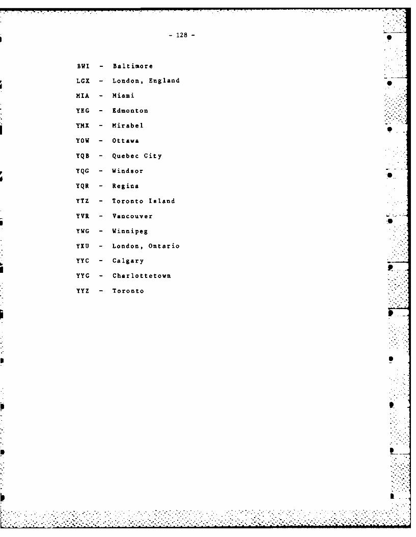
-128-
BWI -Baltimore
LGX -London, England
MIA -Miami
YEG -Edmonton
jYMX - Mirabel
YOW - Ottawa
YQB - Quebec City
FYQG - Windsor
YQR - Regina
YTZ - Toronto Island
YVR - Vancouver-
YWG -Winnipeg
YXU -London, Ontario
YYC - Calgary
YYG - Charlottetown
YYZ -Toronto
-129-
APPENDIX 5
gddash.c:THE ROUTINE TO DRAW DASHED LINES
.
.7 0
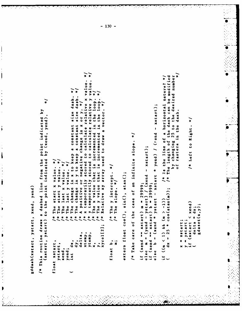
-130-
-4 .0
-43~ -
>- 0
(9I 0 3-.. 0 > > 0 0@3Ia)
A* 4 - '4 '4 CO.0 @3I) 4 14 9.4 0u
*MN 0@ 0 001 0 4) co
A33@@3JJ -W tl 4~ .0 c'4 (A 04 (Dw 41uW ACA4
AW w .4.4 4 0 ) m 041A 933..4 I3 >0 10 0 0 .
G2 a 4 -4 0 U0 41 C4.4 .
-4% 30 : 3 41 41 cc 44 .,403 0 bau 0 01 93 w 0 LW 0U45 U C0-4 -4 W 4) 3 0 93 FA 0
0' 0 a 0 0. - -3 W 410.0u u@3 0 -. 0 (W
0.00. 0. 0OOu( Q3 Q 4 0- -4 ba s l %44e
4) 4)'40@ 0) r 00 @3w
w v -4 r14--4 It %0 0 V30 410 4 1 @ @ @3 'a '4 r4 A 4 0 w * . 44 5-4 w .
> co cc 9~4 03 4014 co 4 0- 4) cc>'4.40 00- - 00 04 cc r. 0 4 4
41 41004 % %44 J @3o 0% @3
0 to ON5-4 .-44 '4 14 0 0 .- 4 414.4 %0
@3 0 .'40 0 141 0 00 0P. > 0 C0% OI@ 1 '41 c caA .,4.0 .,4 -4 * 0 @ 41 4.4
v3 A3. 0@3@ 0w 0 0c -000 0 E-l@H3-4@3@3H@3-.'[email protected] H3 ad EU E44.4. A4. -, w
'4~ ~~ @3 0 V 30 0U **
.4 '410 44 Aj '414 to0@is t 014 *U 0 41@3 0I
S41 w.4 -d 0 -a ca3cc co-40c
>%@ @34c g w v _0 4 @4 ).A 4 IA ' 4 '0 60
-~~ 0 4 0o3- I NI I4 ...4 W W $4@ @ 1. . 4.4 V *0.
0 w 1. v V V m>.. m % x 0: .W @3 @3 03A4 00c 10I . 41 co 0 54 5
co aA C4 a3 @3 041 0 4 co (Ago 49 @5 4 @3 3 - 54 I 44 -4 4.4-4 %44
0 .*4 ~ It%54 ,.14 '44 -3 = *41 -*4 W3 *-4~
0o 14 01
0
00 '-
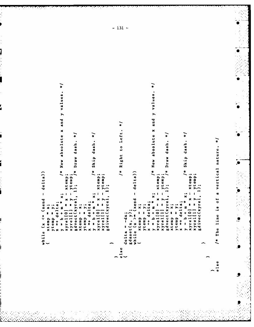
-131
41 41
Ad -A
P o oIu
0 - 0
N N 54W
41 '1
-4- . 04 + 0.
a. 0. 0 45 A 0. P0 A -.30+ 0) 4 .0 +3 '4)0) 4v $.$ 0 10 W-
41 4j 0. 414.50 4 1 %Pm 0 M. bo w %mP 0 m O m>MH0 0
41 ~ ~ ~ ~ c I.. 4)*441M0
cn to
to
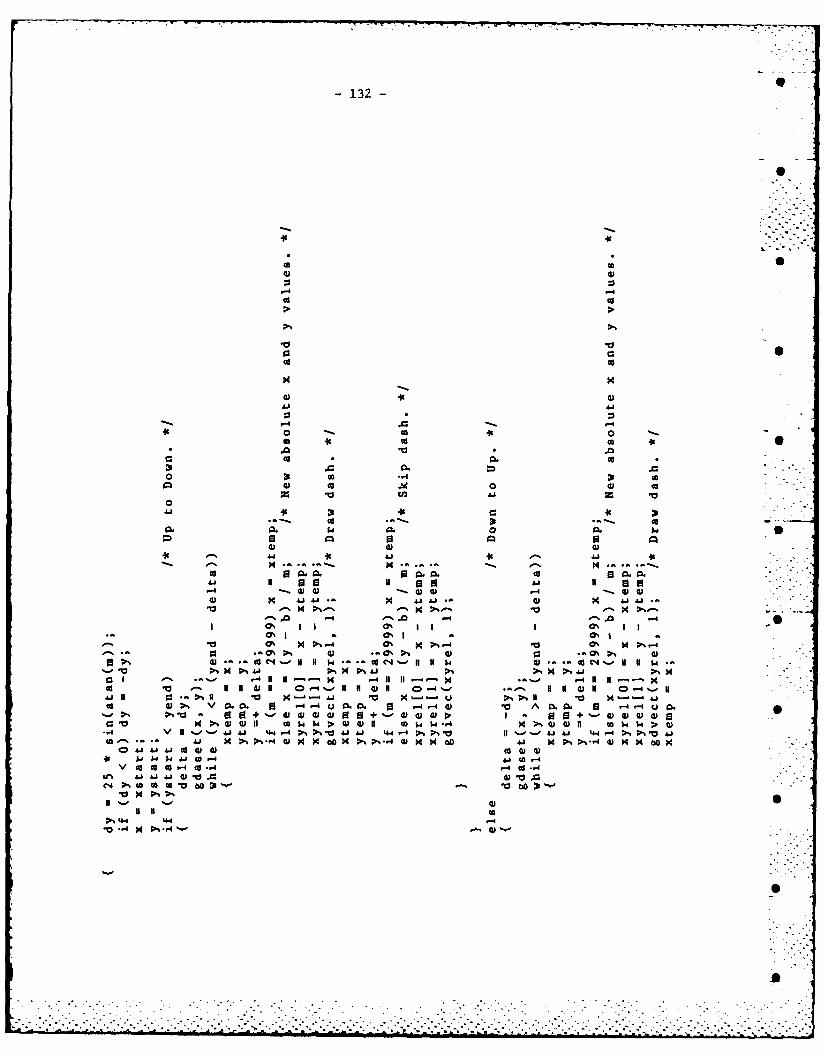
-132-
co 0
0 c
"0 En0
41 1
A 4. 4.1
~O Ii I C
1 -4 0 .0coId0 0 * 0
-04 1 0 .w 0 W) 041 , )n w 14$
4.4P .1 *I' 0d M -4)M m CO'jxx x 0
V CC.~ CO- 0 -O -A-d-
C14 0.l rb 42 W ).3v x
Dl% 4-4 14
-133- 0
0
S
*14
U,
.94* -.-
SW
.4-I
* ~
* *u- 0) 0)
~4 .4JJ.J-~ x
-.. ~ -4a~4 19O~i -~% p4 )...~4
0).- w~..J'--n II I-a~.4-I
'~ U U -- P4II 0)11 0-4'--
P4.-.--' 0~ 0)
* + '- 0) 0) 0) ~.
0)99 ~ P.4 $.a.4
~. ~*.4 0) P4 P4 cc
S
S
*~*. . .
. .
.~ - -. . - - -. . .. .. . - . - - - . . -
S
0
0
S
I
-135-
APPENDIX 6
gdcirc.c:THE ROUTINE TO DRAW CIRCLES
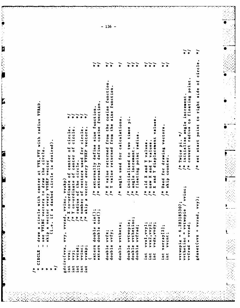
136 -
1J 0
~ - ~ .. -... " -. ,
4, .', I t 4
U
4 0
0 0o 4
ad4 0- 0 r1
4.80
U 4 4 * .,4
toam$0 oa:0P4r- •4 :,,1 0 4 0
40 0 4.4 06 . ..
_4- a1 14 *-u4-
0o . % 441, a U.- w .I
4€ 0 0 0o -4 H 0 0"4 * " •.4 0S - 4 4 w 0 W a a
. 0A 0 .> > -A -A
W ) -0 v 5 10 010- 1 0 4 a .
* .. 1 0 0 . -A44 0 U (
u 0 01 0. -,4 V. 16 I. 5
FA 4-I :3 -4 01 -4 - N u v 0 v64 C0
$4 00 0 co co " 4 6 'U ccgo.6
c 4 44 ' . "4 a0 0 :3 : to .4 0 . -"-"
4.8 *w t,4 .0 60 la 0 0 -4 W 04 *.- .. 4. 1 V
00 00 to4. 0 .4 01 -4 a 60 cl v44WU w v10 6 0 6 w11 >.-' 6 00vptc
1WGo- "1 1.44 1w 000 0 4 14 550 0064 .
a 1 0 0 4 , > a, 0101 -A CO 4 -4 -4 0 0-",,. mm.. ."4 u . k 4.4-. a.- 14 0 .'- 666 I ".4 U .' ."- 0,€ 6 14 . w 0101 144 0 : ,4.,-i010 .-4 0 0 "'.".'"1
-0 1 "V >Uo > 5 -A- -"A . 644 .0 . .
• ,- W :0- CU a I I :s 4. ),,
X*1 4 .4. w01 V.. -101 0aa 1401 I 4 6.0o m . 000 .6 .011 '-01.0. >'4IU
.. .6 > u u v 0 -4 ..0.
r- 4 00$40 (A U'% A 40 0 154.A0 >40 66 010 co -4 0.~' 0
-A 0 00 -,4 0 0 . 1 e4b4--u1 - . • t,.010 6 .-z >: $ 0 , 00 . ,
016 1 0.1001: '4. 1 *-4 .00 ., ,. € .4.'.
go " 0. A, IC' Do% :0, V> >> cc> ' &or, = I ..
I I .- *" .. *'48A 1 €= 0: 00-' '-, , 401 o , .
w 0 0 co >>P.. -
400 -A 0 444 44 A " &444 .4 4 44 0w 0 W 0 0 0 :I >> " m :: a I
4. (A >> NN v 14 00101> >' >S~ *.. .. 40
W 04 .4 06 A0 61 41 ".4 go
> P. P. > H 0 0 . 0 0 0 a > > V. I
S> > 010 4.'0 10.' V 4 A- -- >
~~~~~ 41 "'- Ai0 01 4 0 1
~ 0.'.-' - A -A, -A A -44
r " "L T""r" ;? ''.i d" "'"l " : ." '001--I'''"'~ ") h -" m 'l " 5 5 1 . " .1' T .°'T'I .144. T. .-" ,- .I U2TT" -2-' (T'TT -2, ."- TTT2N. i L21"
"'-' "a '.14"'6 "'0 0 "* " " " ". - .. '-' -° " ' " ' " "" " '-r - - -" -.--"'4" 6 0,- -- 0--' '' ' "o -" ' -;- - ' - "
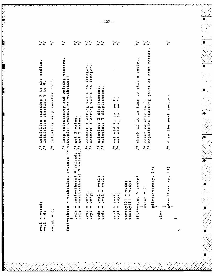
-137-
0
cl 93 0 0
0 .0 000 0 I
l 1a v. 66 0>~ 414 0
op. 0- 00'.4 W. 0be0 be..- isa x>4b
-44 0 -4.44.1 00 -A -4
00 cc m .46 414 -A4. -A 0*&A 41 aid0 010 a
Id10i J.0 616 66 tocc0 0cc 61 4 0 0 55 a0 0
41 4 > 4 661 **I
00 M 0+ u >0 -4 -40044 41 :cc4~. 0c Ai Ai ~ 44 0 -
4144 -A c Ai A00 go0 cc6 4 0 41cc 0o 0. * 41 ".4*14 *44. 1- -0A
-41-4 cc4 -A4 414. * ~ ~ 0 ~41 4) 00 i'
-A -A4 616 00 0 Ai Ai 93c 61r14a16 o 10 04 00 0 o 0
4141 *-4 .0. UU 61
.. 4.. 4 0 1co0 -.- 41 1 6 0
S..~4 > >S >. P s -. cc-
41 >
>. - C C44.N4>6O1 4 44 41 aw.4
00 Go > >> 3
14 4641 .
U 44 W4 M :P. v0.01 P.6 P.. P. 0 0 o >> c o 4
41 .4 4 .1 dI
>1 41 440
090
APPENDIX 7
inread .c:THE ROUTINE TO HANDLE INTERACTIVE INPUT
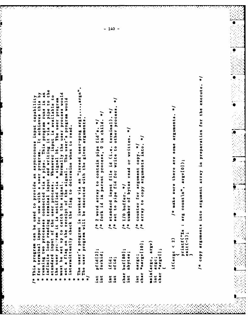
-140-
000
.0 a0 .0o0 Pt
40 WO- U.- u
-p. a'Cw 0 w 6
0 00w0 w0.U14 v 1. w 3 .0Aj -a o a0.0 - a1 a * .wt
UIa0. AC w to w 10 41.4a1%96 ~ 11C 1.). 00-A a41 0 600j4a* > U . *r UO- 0 4) u6
wo ~ sa~ 14 *54 00 V4J M AJ41 E-4 0 m @05 .0a a ~1 a 0
0 0 . 0 14 @1 1 46 # . 510 CC a0W.4 . . 6 1 w40 41 14. ..* - .
00A.1 C0 4 13 4 cc 4 0 a' 0 .
a :5 63 0. @14. 1.. 4.1 as0 *.:3*0 >1 .,0 . 0 a. *oU
41.0 ~ O J 6@1 0. -A4. 3.. :0%-0* ~~~ 0U0" - 1A 4 *06@
UI4 .4 V-.-4A to0 6 0 1 0. 100 01.~ -I v a) 1 r4 14 06 w.
6a0 40C 03 14. A to 0
r..6 ~ U *4 0 0. @11$4 U a51co 014 w~ 2. A. o -4 0 1 @0 W1 P.
a 418 CCJ 0"0 44 C.4 44 w. 9.4 14
-A *0.0-4 .4 1 -01.4 418~ -A W 14 w i-to :0 a v 0 U 4.4 ~4 41 1% - 10 a@ 0@10 IV ONO. 0. ON 0.0
0.04 V u V 004J ~ 41 * 140 6 0 $4 4) -4 0@ .4l 0 -A W0 -A 06 w4 0 uC6 -A Aj 0 w4 l to V6 u4. .4 Q 4-4 4.4 1 '0
U0 M4e 4.4 4 41 U U0. 440 0 WM 0C0 *41r *.4@0 04 .M ~ 41 to44 .4.4100 w14.1 4.4 0a 04 is 0.4 @ 0 Uc
61 @ 041 4A A4444 .@ 4~~4 OO 10 0.@ 0@ is 0.0 0
40 Ai .0-4.0 .44 31 t 641 ON 0 1 :2 CC 4.6146U@4J 4.@1 01 w. w
ae -A Ai u 4 6 4 (4 44 66 a 4 to ..4* 444 0 04 U@. -4* .0 f 4.6 A 4 1 u ~. . .
0 cc 4.. 000 U* ~ ~~~~ 00U 1 UJ0 04 N
411 s.i40. 01 w --V6 0'0- t 3wCC C4 4.41 CC
5" 0 0. 0a w. -1 14 6
UU 0 14 4 0 140 C a 04. U
w14.4r04 C @ 60. v. - 14 -A *g.4.g.$
I* ICd4 to 4 A U -v W 1V4 a 1 5 u0015 4 Nv *01 -. 4 141 4-4 0 w. a 600.1 0.
-A14 4 4.1a40 44j @11.4 *.a a04 UC 4t 1,40
A 0@046 a 66 6.1 AU -.0 CC1 UUC U*~4 040U U1 0 *4 p. . ~ 1U C 14 -
* 6 0'4 4. 41 4.1 4.a. 44 -A 141J.
-A * 4I .4..4 4 , .,f U 0 -4
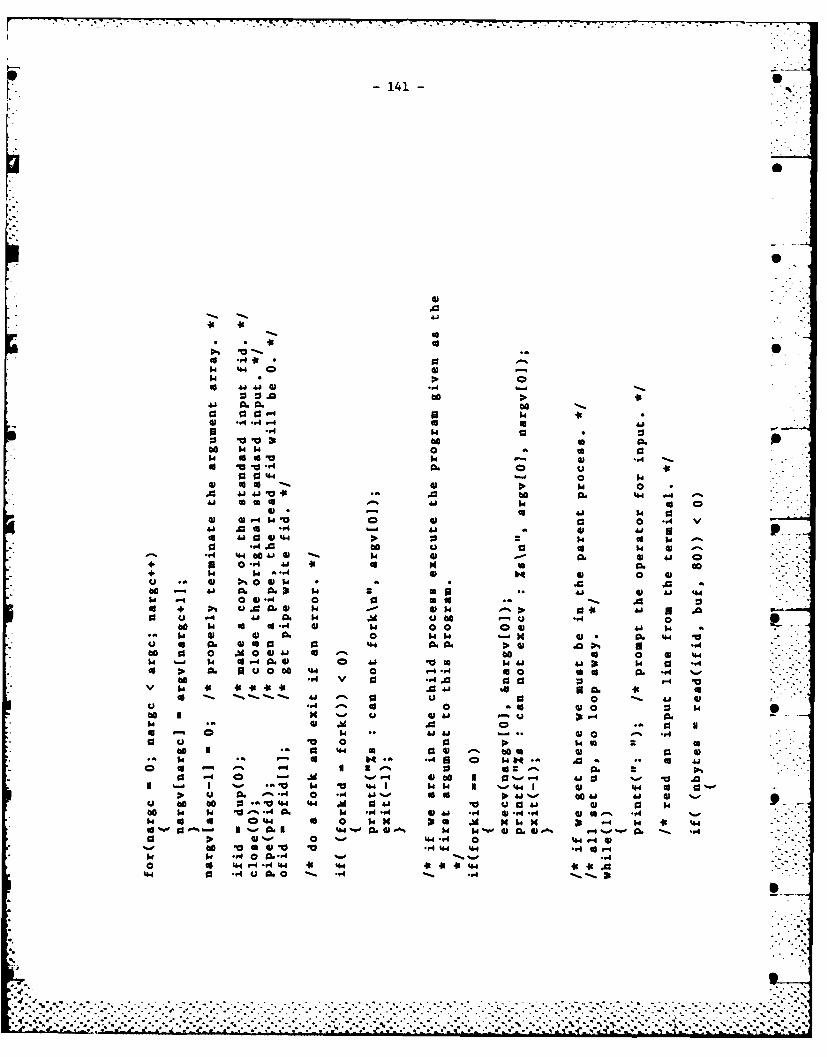
141-
0. m
600
61
u 0 w..
ba 0 0I 0
0 *.4 w 00
O 44441 '.44to 0 00 40 00 a 0
w4 0.0 w 00 0 to 'P
be *.4..-4 0 0 d
to. 5 0 * 0
00 14. 0A.6
0 u06~ V. 00014 0 04 r
*~1 0 0 1 4i0 %--~' .0 0 1 0.0 0. If '-
... 6w v ' %w' I4 0 w0.o
61 0.-454- 0 41 %-o is goP.tu4 oo00 0 . 4 44 t" 61 ai 31 V P
00 w461. w C. Amw .,.4 04 0 - 14 0 14 'go *..I. coU 0 w4 H1 4
4. %- '4 0 .1 %w PA% - .61 40 4 -A4 .8 ' 0 4 -. 0.
to V4 a4~ 6 10 44 04 6
0 a. 44 0. -. P 14 63 4.1 61 44 4
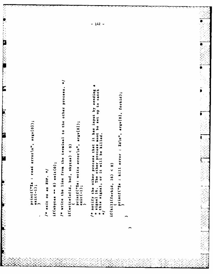
- 142 -
-s4
0A
0 0 :
0 C .4141 v -4U *610
.4 A1 0
z 0 - . -4 .
.0% a94.3 448
416 -l
-I)
00 -.4 -. Q9,0 .
'05-.0
-9 .- 44 H
* 0 0 061) .
10 ' ' 0 e 0 6,1- 0 , .'-
14 .0 6.1 14 1 ,-4a ".1
•. .OP
0l . 0 6 1.
0 .d 0- 0 4.8 '..8. V .*
*,-4 .9 14. "" 14 14, -* a' -
os U- 0, . .0,vI,0 - 484 . -' I,,*4 . . * 0 ., * U.,.
0, . .9 * H.-. .4 0
* -~ U .6.*0 .•
~ 3 61 ~ 9 ... o 0 -
• .. U .0 '4-.-.4 I .0 1.". , ' - , , * , -, -. . .- - .. . . . - . -. . 4. - , ..8 • . . . - . . . . .. . .. . . . . . . . .. . .. . "
*° ' 0 48.° - - . ' - * 0 -" o %" - , - U o
3o '9"- ". • - 4 U. " . " % " " ° . " * - '... ( ; , " - " 9" ,J ', 4 61.' ..' ." . 61. ,. 6"1" . . 9 "4.9 "•4 " . * "44"0*" '. " " . . " . " . '- . .. . " . " • "" " '""" " • ""
3 -143-
APPENDIX 8
ininit .c:THE ROUTINE TO RECEIVE THE~ SIGNAL
THAT INTERACTIVE INPUT IS AVAILABLE
%S
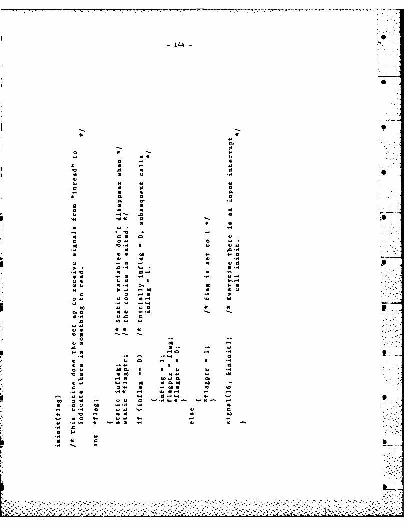
-144-
4.1
08.-A
4. cc 1.
.0 r4 44
- 414 .94441 $. 0 -A 00w t
P41 4 0t
0 0 -4
0 0. 0 to044
0. a
* 0 w41o 60 w 01 -1
5.-*4. co 00A Cw 444 4 0 to 9L(A.
.,I O. 4f - 4 a -4 -
0j "4 44 r4410 to 03 44* ^-4*
a 0 0 -4 -4.
4 w.4 a 41 0
a1 a 4. 14 4 U4 41A
- * 41 ~ - 94 4940
.0 .4 .. . . .
-145-0
APPENDIX 9
THE SYNTAX DIAGRAMS FOR USING THEGRAPHICS DISPLAY LIBRARY ROUTINES
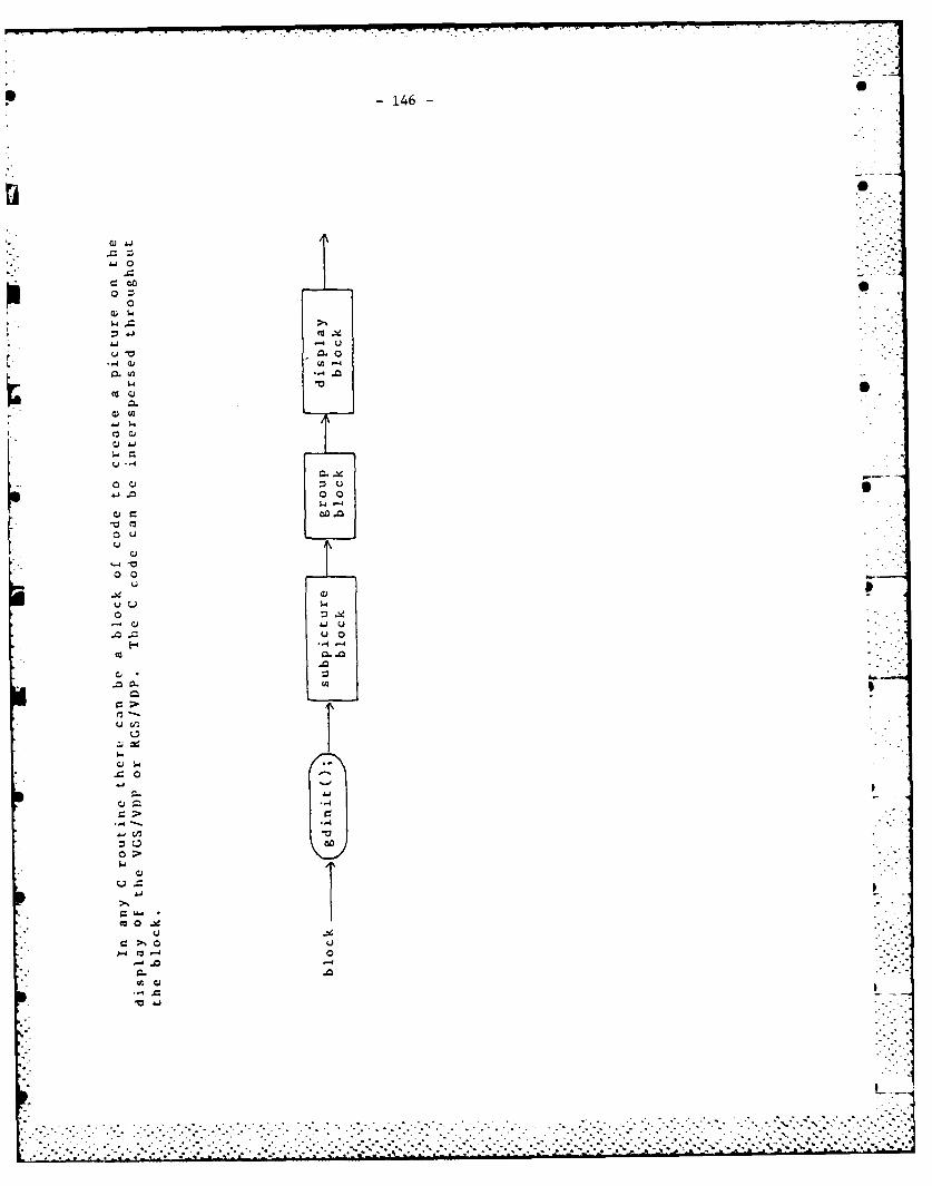
* -146-
T0co Q
.
cz
00
00 0
c0 %
C) 1. 4
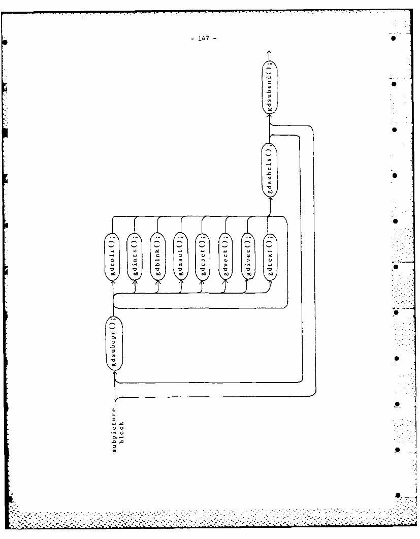
-147-
0-o
0
-4c-i-o 0(42
0
Cs - -~ Cs Cs Cs Cs Cs
((2 .2~ ~.l 1-4 U- 1.1 Cl (24 U Cl Xo -~ ((2 ((2 Ci (24U -I .0 U --4 1.4
.~ .~0(2 00 0(2 00 00 00 00
0
0.0
00
0C.I-
(Jo.- ' 0
0. .- 4
(I) __
~ZT.
* . .. *. * ~ **.* . . . ..
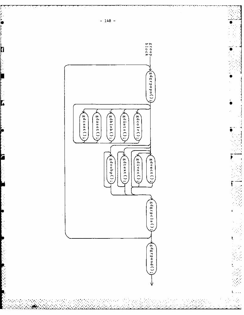
-148-
a, oq
0 0
CL CL 0. C CL
n ca a, I.,. n
m cm o--1
NO 00 OQ 00
CL 0L
'*L
CL
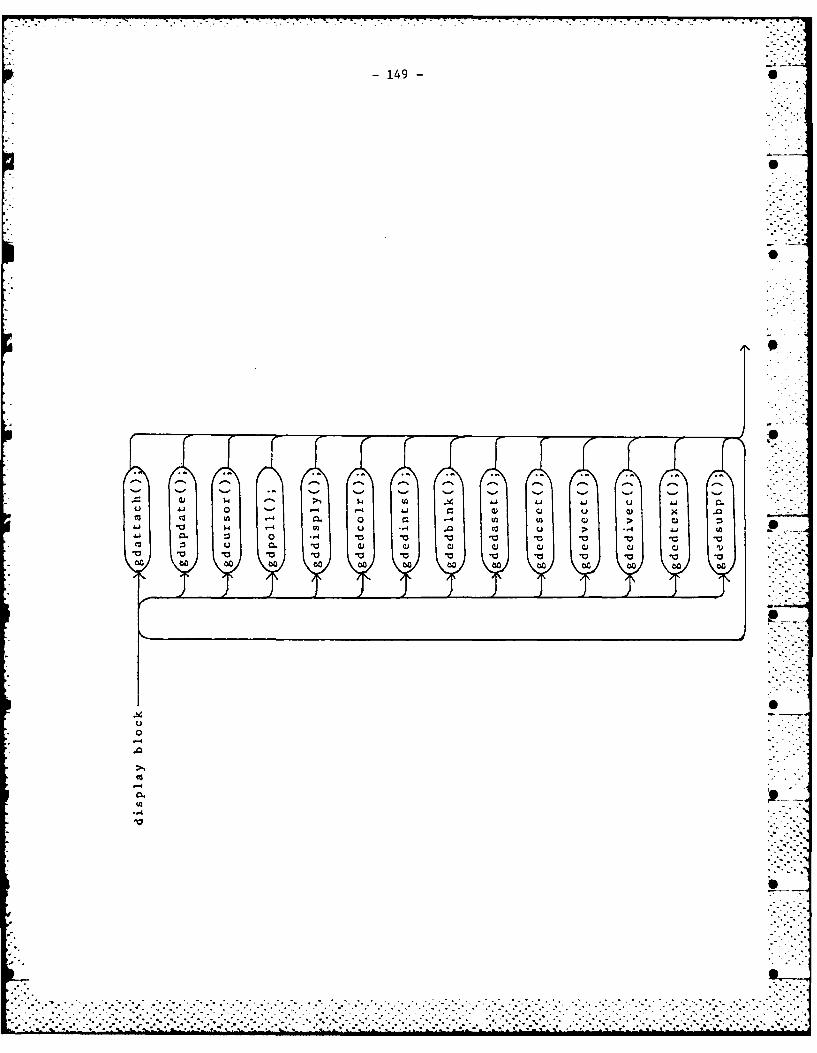
149- 6
00
V 1J 0 a- V. Va U Ca X00 0 o 00 00 -o w2 00 c
100
..... . . . . ..
.. . . . . . .. . .. . . . . . .
- 151-
UNCLASSIFIEDSecurity Clasirfication
DOCUMENT CONTROL DATA - R & 0 0(Security classification of title, body of abstract and indexing annotation must he entered when the overall docu tel is claiSfited)
1 ORIGINATING ACTIVITY 2a. DOCUMENT SECURITY CLASSIFICATION
Defence Research Establishment Ottawa Unclassified
National Defence Headquarters 2b GROUP
Ot-tpajin flnIrn KJA QO7LWa3. DOCUMENT TITLE
A General Area Air Traffic Controller SimulationUsing Colour Graphics
4. DESCRIPTIVE NOTES (Type of report and inclusive dates)
Report5. AUTHORIS) (Last name. first name. middle initial)
Ford, Barbara J. O
6. DOCUMENT DATE 7a. TOTAL NO OF PAGES 7b. NO. OF REFS
September 1983 149 27Ba. PROJECT OR GRANT NO. 9a. ORIGINATOR'S DOCUMENT NUMBER(S)
31B DREO REPORT 890
8b. CONTRACT NO 9b. OTHER DOCUMENT NO.(S) (Any other numbers that may beassigned this document)
10. DISTRIBUTION STATEMENT
Unlimited distribution
11 SUPPLEMENTARY NOTES 12. SPONSORING ACTIVITY
CRAD
13. ABSTRACT
The increased speed of aircraft and a greater density of airtraffic are overtaxing air traffic controllers. Automation of someportions of the controller's information and the use of colour to highlightdangerous situations will make the controller's work easier and possibly
more accurate. One of the major aims of the study is to show that the
use of different colours to indicate varying distances between aircraftis a definite improvement over a monochrome display. The other major aim
is to study the advantages and disadvantages of vector display and rasterdisplay technologies when applied to the air traffic controller scenario. -"
A new set of graphics display routines was developed to be used for the
simulation. Much consideration was given to the best methods to optimizethe display routines, with attention given to real-time constraints.
7 7-16.
.%I_
- 152 -
UNCLASS IF IEDSecurity Classification
KEY WORDS 0
_Secondary DisplayColour GraphicsAir Traffic ControlProgramming Guide 0Vector Refresh DisplayRaster Refresh DisplayMonochrome Display ComparisonSimulationInteraction
INSTRUCTIONS
1. ORIGINATING ACTIVITY: Enter the name and address of the 9bs. OTHER DOCUMENT NUMBER(S): If the document has beenorganization issuing the document, assigned any other document numbers (either by the originator
or by the sponsor). also enter this number(s).2a. DOCUMENT SECURITY CLASSIFICATION: Enter the overall -
security classification of the document including special warning 10. DISTRIBUTION STATEMENT: Enter any limitations on 5terms whenever applicable, further dissemination of the document, other than those imposed . -
by security classification, using standard statements such as:2b. GROUP Enter security reclassification group number. The three
groups are defined in Appendix ', of the DRB Security Regulations. I1) "Ouslified requesters may obtain copies of thisdocument from their defence documentation center."
* 3. DOCUMENT TITLE: Enter the complete document title in allcapital letters. Titles in all cases should be unclassified. If a (2) "Announcement and dissemination of this documentsufficiently descriptive title cannot be selected without classifi- is not authorized without prior approval fromcation. show title classification with the usual one-capital-letter originating activity.
'
abbreviation in parentheses immediately following the title.11. SUPPLEMENTARY NOTES. Use for additional explanatory
4. DESCRIPTIVE NOTES: Enter the category of document. e.g. notes.technical report, technical note or technical letter. If awopri-ate, enter the type of document. eg. interim, progress. 12. SPONSORING ACTIVITY: Enter the name of the departmentalsummary, annual or final. Give the inclusive dates when a prolect office or laboratory sponsoring the research andspecific reporting period is covered. development. Include address.
5. AUTHOR(S): Enter the name(s) of authorls) as shown on or 13. ABSTRACT: Enter an abstract giving a brief and factualin the document. Enter last name, first name, middle initial summary of the document, even though it may also appearIf military, show rank. The name of the principal author is an elsewhere in the body of the document itself. It is highlyabsolute minimum requirement desirable that the abstract of classified documents be unclassi-
fied. Each paragraph of the abstract shall end with an6. DOCUMENT DATE: Enter the date (month, year) of indication of the security classification of the information
Establishment approval for publication of the document. in the paragraph (unless the document itself is unclassifiedlrepresented as ITS), (S). (C), (R). or (U).
7 a. TOTAL NUMBER OF PAGES. The total oge count shouldfollow normal pagination procedures. i.e.. enter the number The length of the abstract should be limited to 20 single-spacedof pages containing information, standard typewritten lines; 711 inches long.
7b. NUMBER OF REFERENCES: Enter the totml number of 14. KEY WORDS: Key words are technically meaningful terms orreferences cited in the document short phrases that characterize a document and could be helpful
in cataloging the document. Key words should be selected so8a. PROJECT OR GRANT NUMBER. If appropriate, enter the that no security classification is required. Identifiers. such as
applicable research and development prolect or grant number equipment model designation, trade name, military prolect codeunder which the document was written name, geographic location, may be used as key words but will
be followed by an indication of technical context.8b. CONTRACT NUMBER' If appropriate, enter the applicable
number under which the document was written.
ga. ORIGINATOR'S DOCUMENT NUMBERISI: Enter theofficial document number by which the document will beidentified and controlled by the originating activity, Thisnumber must be unique to this document.
..... ...--... .- - - - -. . . . . . . . . . . . . . . . . . .. . . . . . . .
,:-....-.. . . . . . . . . . . . ...-..-........- ....- -.....,.....- .. ,.:..-.....-.,.-..-....-.-..-....-..-...............-... .... .. -- .... ....-........... ....
*FILMED
6-85
DTIC5 7,


![[Piano method] Progris A Modern Method For Keyboard Study Vol4 (2)](https://img.pdfslide.us/doc/110x75/5515a7bb4979591b1e8b4e29/piano-method-progris-a-modern-method-for-keyboard-study-vol4-2.jpg)

![[Piano Method] Progris a Modern Method for Keyboard Study Vol2](https://img.pdfslide.us/doc/110x75/55cf96b0550346d0338d26f8/piano-method-progris-a-modern-method-for-keyboard-study-vol2.jpg)