Embed Size (px)
Citation preview
Business Process Model and Notation, v2.0 21
7 Overview
There has been much activity in the past few years in developing web service-based XML execution languages for Business Process Management (BPM) systems. Languages such as WSBPEL provide a formal mechanism for the definition of business processes. The key element of such languages is that they are optimized for the operation and inter-operation of BPM Systems. The optimization of these languages for software operations renders them less suited for direct use by humans to design, manage, and monitor Business Processes. WSBPEL has both graph and block structures and utilizes the principles of formal mathematical models, such as pi-calculus1. This technical underpinning provides the foundation for business process execution to handle the complex nature of both internal and B2B interactions and take advantage of the benefits of Web services. Given the nature of WSBPEL, a complex Business Process could be organized in a potentially complex, disjointed, and unintuitive format that is handled very well by a software system (or a computer programmer), but would be hard to understand by the business analysts and managers tasked to develop, manage, and monitor the Process. Thus, there is a human level of “inter-operability” or “portability” that is not addressed by these web service-based XML execution languages.
Business people are very comfortable with visualizing Business Processes in a flow-chart format. There are thousands of business analysts studying the way companies work and defining Business Processes with simple flow charts. This creates a technical gap between the format of the initial design of Business Processes and the format of the languages, such as WSBPEL, that will execute these Business Processes. This gap needs to be bridged with a formal mechanism that maps the appropriate visualization of the Business Processes (a notation) to the appropriate execution format (a BPM execution language) for these Business Processes.
Inter-operation of Business Processes at the human level, rather than the software engine level, can be solved with standardization of the Business Process Model and Notation (BPMN). BPMN provides a multiple diagrams, which are designed for use by the people who design and manage Business Processes. BPMN also provides a mapping to an execution language of BPM Systems (WSBPEL). Thus, BPMN would provide a standard visualization mechanism for Business Processes defined in an execution optimized business process language.
BPMN provides businesses with the capability of understanding their internal business procedures in a graphical notation and will give organizations the ability to communicate these procedures in a standard manner. Currently, there are scores of Process modeling tools and methodologies. Given that individuals will move from one company to another and that companies will merge and diverge, it is likely that business analysts need to understand multiple representations of Business Processes—potentially different representations of the same Process as it moves through its lifecycle of development, implementation, execution, monitoring, and analysis. Therefore, a standard graphical notation will facilitate the understanding of the performance Collaborations and business transactions within and between the organizations. This will ensure that businesses will understand themselves and participants in their business and will enable organizations to adjust to new internal and B2B business circumstances quickly. BPMN follows the tradition of flowcharting notations for readability and flexibility. In addition, the BPMN execution semantics is fully formalized. The OMG is using the experience of the business process notations that have preceded BPMN to create the next generation notation that combines readability, flexibility, and expandability.
BPMN will also advance the capabilities of traditional business process notations by inherently handling B2B Business Process concepts, such as public and private Processes and Choreographies, as well as advanced modeling concepts, such as exception handling, transactions, and compensation.
1. See Milner, 1999, “Communicating and Mobile Systems: the –-Calculus,” Cambridge University Press. ISBN 0 521 64320 1 (hc.) ISBN 0 521 65869 1 (pbk.)
22 Business Process Model and Notation, v2.0
7.1 BPMN ScopeThis specification provides a notation and model for Business Processes and an interchange format that can be used to exchange BPMN Process definitions (both domain model and diagram layout) between different tools. The goal of the specification is to enable portability of Process definitions, so that users can take Process definitions created in one vendor’s environment and use them in another vendor’s environment.
The BPMN 2.0 specification extends the scope and capabilities of the BPMN 1.2 in several areas:
• Formalizes the execution semantics for all BPMN elements
• Defines an extensibility mechanism for both Process model extensions and graphical extensions
• Refines Event composition and correlation
• Extends the definition of human interactions
• Defines a Choreography model
This specification also resolves known BPMN 1.2 inconsistencies and ambiguities.
BPMN is constrained to support only the concepts of modeling that are applicable to Business Processes. This means that other types of modeling done by organizations for business purposes is out of scope for BPMN. Therefore, the following are aspects that are out of the scope of this specification:
• Definition of organizational models and resources
• Modeling of functional breakdowns
• Data and information models
• Modeling of strategy
• Business rules models
Since these types of high-level modeling either directly or indirectly affects Business Processes, the relationships between BPMN and other high-level business modeling can be defined more formally as BPMN and other specifications are advanced.
While BPMN shows the flow of data (Messages), and the association of data artifacts to Activities, it is not a data flow language. In addition, operational simulation, monitoring and deployment of Business Processes are out of scope of this specification.
BPMN 2.0 can be mapped to more than one platform dependent process modeling language, e.g. WS-BPEL 2.0. This document includes a mapping of a subset of BPMN to WS-BPEL 2.0. Mappings to other emerging standards are considered to be separate efforts.
The specification utilizes other standards for defining data types, Expressions and service operations. These standards are XML Schema, XPath, and WSDL, respectively.
Business Process Model and Notation, v2.0 23
7.1.1 Uses of BPMN
Business Process modeling is used to communicate a wide variety of information to a wide variety of audiences. BPMN is designed to cover many types of modeling and allows the creation of end-to-end Business Processes. The structural elements of BPMN allow the viewer to be able to easily differentiate between sections of a BPMN Diagram. There are three basic types of sub-models within an end-to-end BPMN model:
• Processes (Orchestration), including:
• Private non-executable (internal) Business Processes• Private executable (internal) Business Processes• Public Processes
• Choreographies
• Collaborations, which can include Processes and/or Choreographies• A view of Conversations
Private (Internal) Business Processes
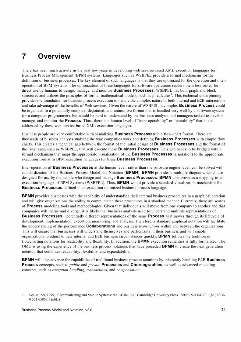
Private Business Processes are those internal to a specific organization. These Processes have been generally called workflow or BPM Processes (see Figure 10.4). Another synonym typically used in the Web services area is the Orchestration of services. There are two (2) types of private Processes: executable and non-executable. An executable Process is a Process that has been modeled for the purpose of being executed according to the semantics defined in Chapter 14. Of course, during the development cycle of the Process, there will be stages where the Process does not have enough detail to be “executable.” A non-executable Process is a private Process that has been modeled for the purpose of documenting Process behavior at a modeler-defined level of detail. Thus, information needed for execution, such as formal condition Expressions are typically not included in a non-executable Process.
If a swimlanes-like notation is used (e.g., a Collaboration, see below) then a private Business Process will be contained within a single Pool. The Process flow is therefore contained within the Pool and cannot cross the boundaries of the Pool. The flow of Messages can cross the Pool boundary to show the interactions that exist between separate private Business Processes.
Figure 7.1 - Example of a private Business Process
Public Processes
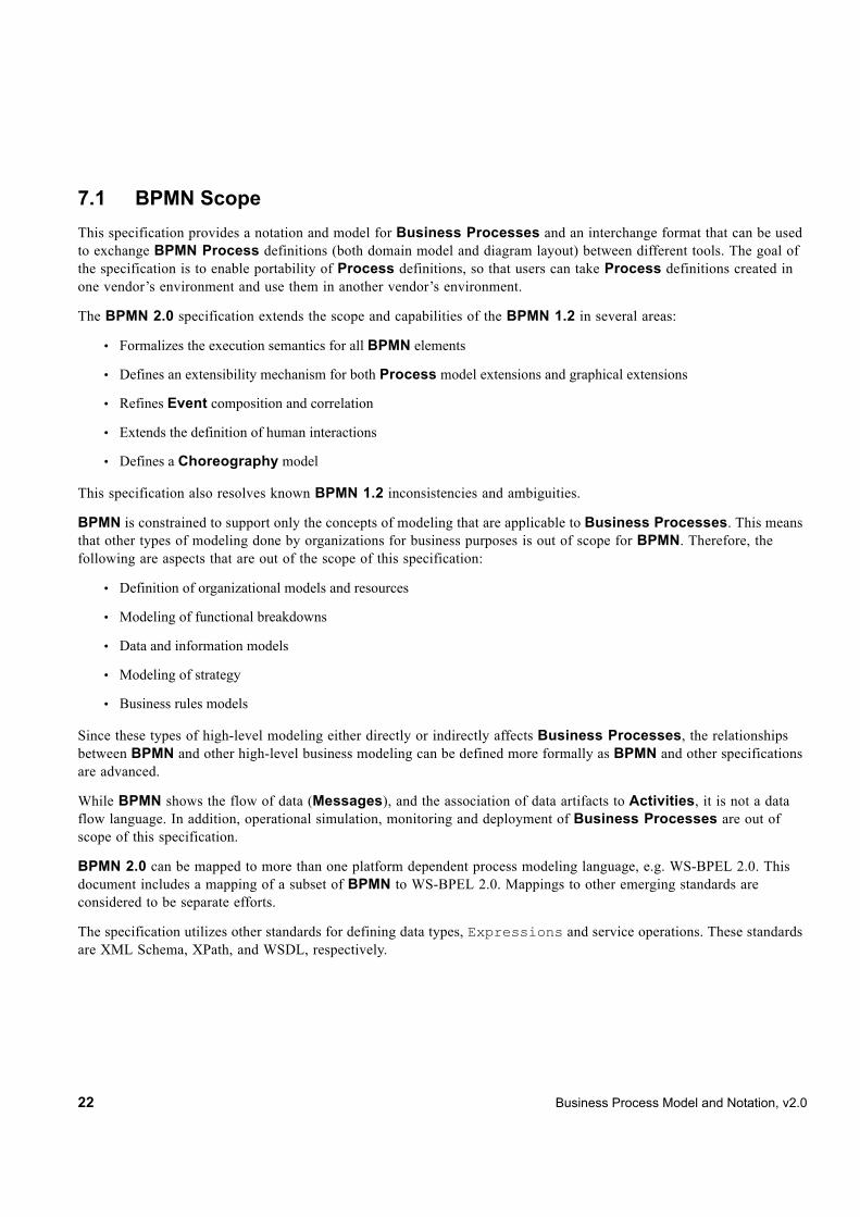
A public Process represents the interactions between a private Business Process and another Process or Participant (see Figure 7.2). Only those Activities that are used to communicate to the other Participant(s) are included in the public Process. All other “internal” Activities of the private Business Process are not shown in the public Process. Thus, the public Process shows to the outside world the Message Flows and the order of those Message Flows that are needed to interact with that Process. Public Processes can be modeled separately or within a Collaboration to show the flow of Messages between the public Process Activities and other Participants. Note that the public type of Process was named “abstract” in BPMN 1.2.
Determine Premium of
Policy
Determine Order is
Complete
Check Record of Applicant
Approve or Reject
Policy
Notify Applicant of Approval or Rejection
24 Business Process Model and Notation, v2.0
Figure 7.2 - Example of a public Process
Collaborations
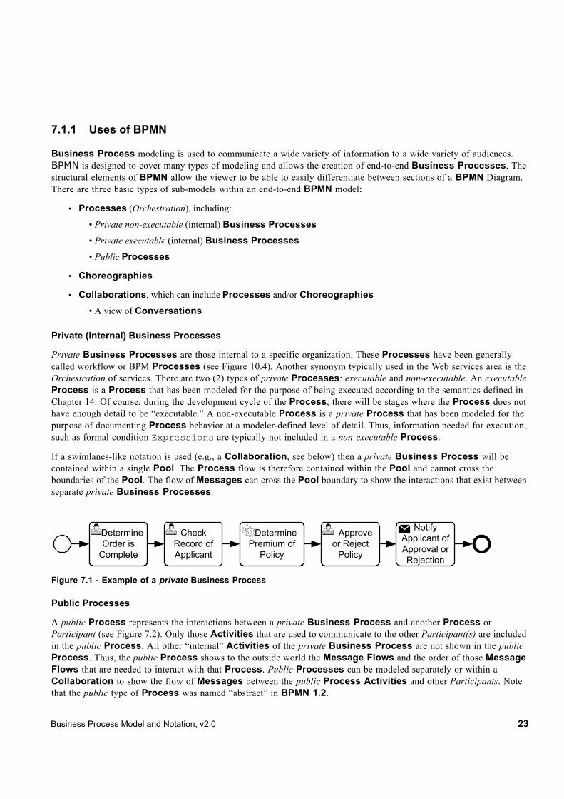
A Collaboration depicts the interactions between two or more business entities. A Collaboration usually contains two (2) or more Pools, representing the Participants in the Collaboration. The Message exchange between the Participants is shown by a Message Flow that connects two (2) Pools (or the objects within the Pools). The Messages associated with the Message Flows can also be shown. The Collaboration can be shown as two or more public Processes communicating with each other (see Figure 7.3). With a public Process, the Activities for the Collaboration participants can be considered the “touch-points” between the participants. The corresponding internal (executable) Processes are likely to have much more Activity and detail than what is shown in the public Processes. Or a Pool MAY be empty, a “black box.” Choreographies MAY be shown “in between” the Pools as they bisect the Message Flows between the Pools. All combinations of Pools, Processes, and a Choreography are allowed in a Collaboration.
Pat
ient
I want to see doctor
Send Appt.
Go see doctor
Receive Symptoms
I feel sickPickup your medicine
and you can leave
Receive Medicine Request
need my medicine
Here is your medicine
Receive Doctor
Request
Send Medicine
Send Prescription
Pickup
Business Process Model and Notation, v2.0 25
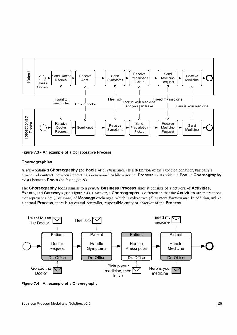
Figure 7.3 - An example of a Collaborative Process
Choreographies
A self-contained Choreography (no Pools or Orchestration) is a definition of the expected behavior, basically a procedural contract, between interacting Participants. While a normal Process exists within a Pool, a Choreography exists between Pools (or Participants).
The Choreography looks similar to a private Business Process since it consists of a network of Activities, Events, and Gateways (see Figure 7.4). However, a Choreography is different in that the Activities are interactions that represent a set (1 or more) of Message exchanges, which involves two (2) or more Participants. In addition, unlike a normal Process, there is no central controller, responsible entity or observer of the Process.
Figure 7.4 - An example of a Choreography
Send Doctor Request
I want to see doctor
Illness Occurs
Send Appt.
Receive Appt.
Go see doctor
Send Symptoms
Receive Symptoms
I feel sick
Receive Prescription
Pickup
Pickup your medicine and you can leave
Send Medicine Request
Receive Medicine Request
I need my medicine
Receive Medicine
Here is your medicine
Receive Doctor
Request
Send Medicine
Send Prescription
Pickup
Pat
ient
Rec
eptio
nist
/D
octo
r
Doctor Request
Patient
Dr. Office
Handle Symptoms
Patient
Dr. Office
Handle Prescription
Patient
Dr. Office
Handle Medicine
Patient
Dr. Office
I want to see the Doctor
Go see the Doctor
I feel sickI need my medicine
Here is your medicine
Pickup your medicine, then
leave

26 Business Process Model and Notation, v2.0
Conversations
The Conversation diagram is a particular usage of and an informal description of a Collaboration diagram. However, the Pools of a Conversation usually do not contain a Process and a Choreography is usually not placed in between the Pools of a Conversation diagram. A Conversation is the logical relation of Message exchanges. The logical relation, in practice, often concerns a business object(s) of interest, e.g., “Order,” “Shipment and Delivery,” or “Invoice.”
Message exchanges are related to each other and reflect distinct business scenarios. For example, in logistics, stock replenishments involve the following types scenarios: creation of sales orders; assignment of carriers for shipments combining different sales orders; crossing customs/quarantine; processing payment and investigating exceptions. Thus, a Conversation diagram, as shown in Figure 7.5, shows Conversations (as hexagons) between Participants (Pools). This provides a “bird’s eye” perspective of the different Conversations which relate to the domain.
Figure 7.5 - An example of a Conversation diagram
Diagram Point of View
Since a BPMN Diagram MAY depict the Processes of different Participants, each Participant could view the Diagram differently. That is, the Participants have different points of view regarding how the Processes will apply to them. Some of the Activities will be internal to the Participant (meaning performed by or under control of the Participant) and other
Delivery / Dispatch Plan
Delivery Negotiations
Shipment Schedule
Delivery / Dispatch Plan
Delivery / Dispatch Plan Carrier Planning
Coverage Notification
Clearance Pre-Notification
Truck Breakdown Provision
Arrival/Pickup Confirmation
Traffic Optimization Guidance
Breakdown Service
Locative Service
Insurance
Shipper
SupplierRetailer
Consignee
Customs/Quarantine
ConsolidatorCarrier
(Land, Sea, Rail, or Air)
Business Process Model and Notation, v2.0 27
Activities will be external to the Participant. Each Participant will have a different perspective as to which are internal and external. At runtime, the difference between internal and external Activities is important in how a Participant can view the status of the Activities or trouble-shoot any problems. However, the Diagram itself remains the same. Figure 7.3 displays a Business Process that has two points of view. One point of view is of a Patient, the other is of the Doctor’s office. The Diagram shows the Activities of both participants in the Process, but when the Process is actually being performed, each Participant will only have control over their own Activities. Although the Diagram point of view is important for a viewer of the Diagram to understand how the behavior of the Process will relate to that viewer, BPMN will not currently specify any graphical mechanisms to highlight the point of view. It is open to the modeler or modeling tool vendor to provide any visual cues to emphasize this characteristic of a Diagram.
Understanding the Behavior of Diagrams
Throughout this document, we discuss how Sequence Flows are used within a Process. To facilitate this discussion, we employ the concept of a token that will traverse the Sequence Flows and pass through the elements in the Process. A token is a theoretical concept that is used as an aid to define the behavior of a Process that is being performed. The behavior of Process elements can be defined by describing how they interact with a token as it “traverses” the structure of the Process. However, modeling and execution tools that implement BPMN are NOT REQUIRED to implement any form of token.
A Start Event generates a token that MUST eventually be consumed at an End Event (which MAY be implicit if not graphically displayed). The path of tokens should be traceable through the network of Sequence Flows, Gateways, and Activities within a Process.
Note – A token does not traverse a Message Flow since it is a Message that is passed down a Message Flow (as the name implies).
7.2 BPMN ElementsIt should be emphasized that one of the drivers for the development of BPMN is to create a simple and understandable mechanism for creating Business Process models, while at the same time being able to handle the complexity inherent to Business Processes. The approach taken to handle these two conflicting requirements was to organize the graphical aspects of the notation into specific categories. This provides a small set of notation categories so that the reader of a BPMN diagram can easily recognize the basic types of elements and understand the diagram. Within the basic categories of elements, additional variation and information can be added to support the requirements for complexity without dramatically changing the basic look and feel of the diagram. The five (5) basic categories of elements are:
• Flow Objects
• Data
• Connecting Objects
• Swimlanes
• Artifacts
Flow Objects are the main graphical elements to define the behavior of a Business Process. There are three (3) Flow Objects:
• Events
• Activities
28 Business Process Model and Notation, v2.0
• Gateways
Data is represented with the four (4) elements:
• Data Objects
• Data Inputs
• Data Outputs
• Data Stores
There are four (4) ways of connecting the Flow Objects to each other or other information. There are four (4) Connecting Objects:
• Sequence Flows
• Message Flows
• Associations
• Data Associations
There are two (2) ways of grouping the primary modeling elements through “Swimlanes:”
• Pools
• Lanes
Artifacts are used to provide additional information about the Process. There are two (2) standardized Artifacts, but modelers or modeling tools are free to add as many Artifacts as necessary. There could be additional BPMN efforts to standardize a larger set of Artifacts for general use or for vertical markets. The current set of Artifacts includes:
• Group
• Text Annotation
7.2.1 Basic BPMN Modeling Elements
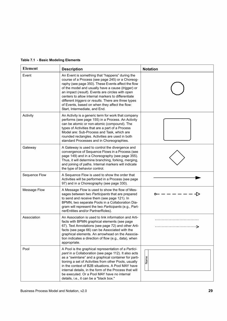
Table 7.1 displays a list of the basic modeling elements that are depicted by the notation.
Business Process Model and Notation, v2.0 29
Table 7.1 - Basic Modeling Elements
Element Description NotationEvent An Event is something that “happens” during the
course of a Process (see page 245) or a Choreog-raphy (see page 350). These Events affect the flow of the model and usually have a cause (trigger) or an impact (result). Events are circles with open centers to allow internal markers to differentiate different triggers or results. There are three types of Events, based on when they affect the flow: Start, Intermediate, and End.
Activity An Activity is a generic term for work that company performs (see page 155) in a Process. An Activity can be atomic or non-atomic (compound). The types of Activities that are a part of a Process Model are: Sub-Process and Task, which are rounded rectangles. Activities are used in both standard Processes and in Choreographies.
Gateway A Gateway is used to control the divergence and convergence of Sequence Flows in a Process (see page 149) and in a Choreography (see page 355). Thus, it will determine branching, forking, merging, and joining of paths. Internal markers will indicate the type of behavior control.
Sequence Flow A Sequence Flow is used to show the order that Activities will be performed in a Process (see page 97) and in a Choreography (see page 330).
Message Flow A Message Flow is used to show the flow of Mes-sages between two Participants that are prepared to send and receive them (see page 121). In BPMN, two separate Pools in a Collaboration Dia-gram will represent the two Participants (e.g., Part-nerEntities and/or PartnerRoles).
Association An Association is used to link information and Arti-facts with BPMN graphical elements (see page 67). Text Annotations (see page 72) and other Arti-facts (see page 66) can be Associated with the graphical elements. An arrowhead on the Associa-tion indicates a direction of flow (e.g., data), when appropriate.
Pool A Pool is the graphical representation of a Partici-pant in a Collaboration (see page 112). It also acts as a “swimlane” and a graphical container for parti-tioning a set of Activities from other Pools, usually in the context of B2B situations. A Pool MAY have internal details, in the form of the Process that will be executed. Or a Pool MAY have no internal details, i.e., it can be a "black box."
Nam
e

30 Business Process Model and Notation, v2.0
7.2.2 Extended BPMN Modeling Elements
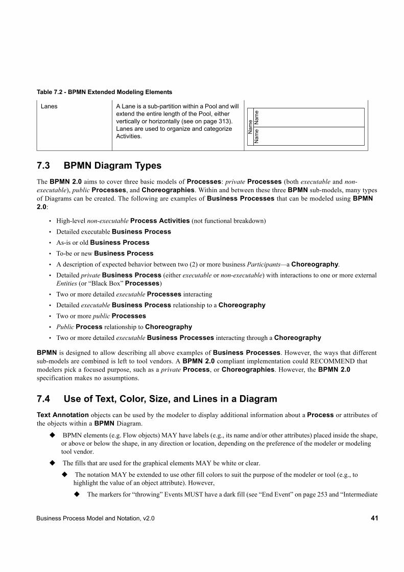
Table 7.2 displays a more extensive list of the Business Process concepts that could be depicted through a business process modeling notation.
Lane A Lane is a sub-partition within a Process, some-times within a Pool, and will extend the entire length of the Process, either vertically or horizon-tally (see on page 313). Lanes are used to orga-nize and categorize Activities.
Data Object Data Objects provide information about what Activ-ities require to be performed and/or what they pro-duce (see page 212), Data Objects can represent a singular object or a collection of objects. Data Input and Data Output provide the same informa-tion for Processes.
Message A Message is used to depict the contents of a com-munication between two Participants (as defined by a business PartnerRole or a business Partner-Entity—see on page 93).
Group (a box around a group of objects within the same category)
A Group is a grouping of graphical elements that are within the same Category (see page 71). This type of grouping does not affect the Sequence Flows within the Group. The Category name appears on the diagram as the group label. Cate-gories can be used for documentation or analysis purposes. Groups are one way in which Catego-ries of objects can be visually displayed on the dia-gram.
Text Annotation (attached with an Association)
Text Annotations are a mechanism for a modeler to provide additional text information for the reader of a BPMN Diagram (see page 72).
Table 7.2 - BPMN Extended Modeling Elements
Element Description Notation
Table 7.1 - Basic Modeling Elements
Nam
e Nam
eN
ame
Descriptive Text Here

Business Process Model and Notation, v2.0 31
Event An Event is something that “happens” during the course of a Process (see page 245) or a Choreography (see page 350). These Events affect the flow of the model and usually have a cause (Trigger) or an impact (Result). Events are circles with open centers to allow internal markers to differentiate different Trig-gers or Results. There are three types of Events, based on when they affect the flow: Start, Intermediate, and End.
Flow Dimension (e.g., Start, Intermediate, End)
Start
Intermediate
End
As the name implies, the Start Event indicates where a particular Process (see page 245) or Choreography (see page 350) will start.
Intermediate Events occur between a Start Event and an End Event. They will affect the flow of the Process (see page 257) or Chore-ography (see page 350), but will not start or (directly) terminate the Process.
As the name implies, the End Event indicates where a Process (see page 253) or Choreog-raphy (see page 354) will end.
Start
Intermediate
End
Type Dimension (e.g., None, Message, Timer, Error, Cancel, Compen-sation, Conditional, Link, Signal, Multiple, Termi-nate.)
The Start and some Intermediate Events have “triggers” that define the cause for the Event (see section entitled “Start Event” on page 245 and section entitled “Intermediate Event” on page 257). There are multiple ways that these events can be triggered. End Events MAY define a “result” that is a conse-quence of a Sequence Flow path ending. Start Events can only react to (“catch”) a trig-ger. End Events can only create (“throw”) a result. Intermediate Events can catch or throw triggers. For the Events, triggers that catch, the markers are unfilled, and for triggers and results that throw, the markers are filled.
Additionally, some Events, which were used to interrupt Activities in BPMN 1.1, can now be used in a mode that does not interrupt. The boundary of these Events is dashed (see fig-ure to the right).
Table 7.2 - BPMN Extended Modeling Elements
Message
Timer
Error
Compensation
Conditional
Link
Multiple
Terminate
Signal
Cancel
Escalation
“Throwing”“Catching” Non-Interrupting
ParallelMultiple
32 Business Process Model and Notation, v2.0
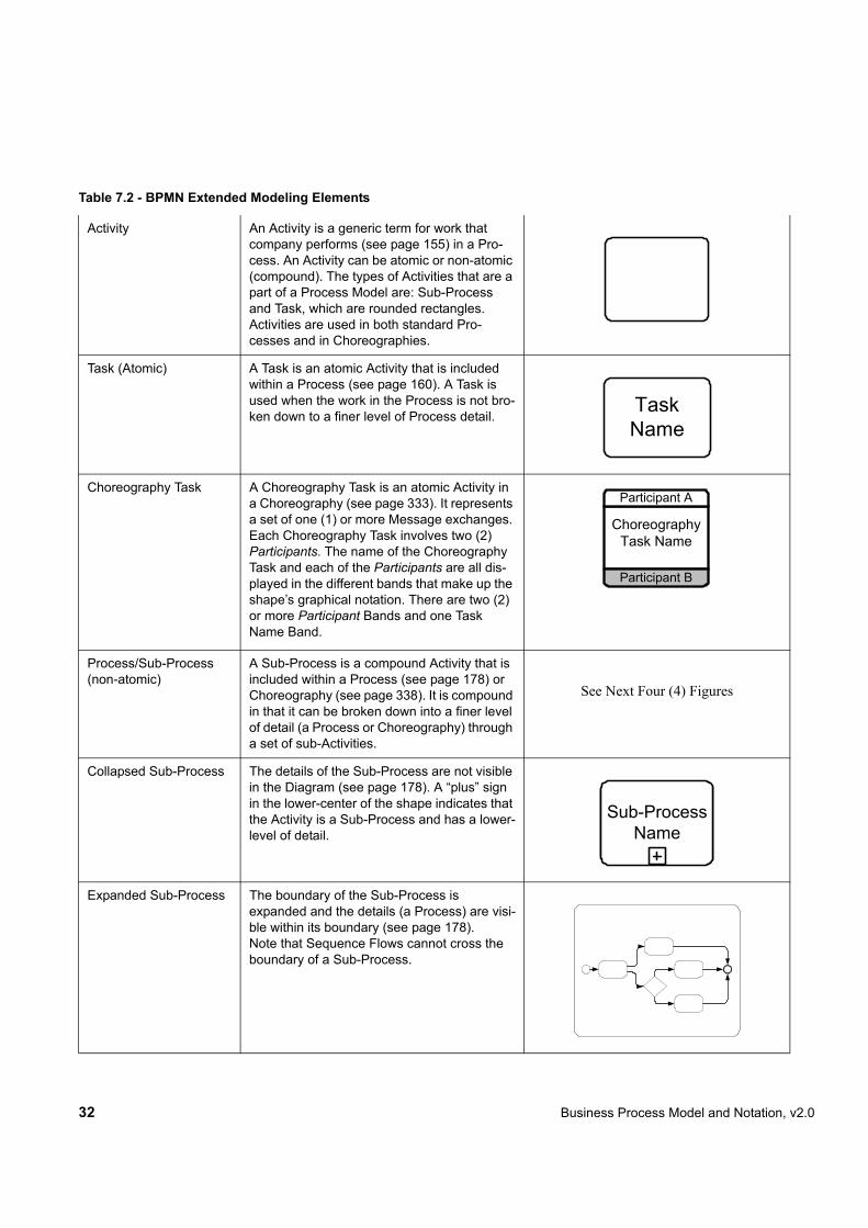
Activity An Activity is a generic term for work that company performs (see page 155) in a Pro-cess. An Activity can be atomic or non-atomic (compound). The types of Activities that are a part of a Process Model are: Sub-Process and Task, which are rounded rectangles. Activities are used in both standard Pro-cesses and in Choreographies.
Task (Atomic) A Task is an atomic Activity that is included within a Process (see page 160). A Task is used when the work in the Process is not bro-ken down to a finer level of Process detail.
Choreography Task A Choreography Task is an atomic Activity in a Choreography (see page 333). It represents a set of one (1) or more Message exchanges. Each Choreography Task involves two (2) Participants. The name of the Choreography Task and each of the Participants are all dis-played in the different bands that make up the shape’s graphical notation. There are two (2) or more Participant Bands and one Task Name Band.
Process/Sub-Process (non-atomic)
A Sub-Process is a compound Activity that is included within a Process (see page 178) or Choreography (see page 338). It is compound in that it can be broken down into a finer level of detail (a Process or Choreography) through a set of sub-Activities.
See Next Four (4) Figures
Collapsed Sub-Process The details of the Sub-Process are not visible in the Diagram (see page 178). A “plus” sign in the lower-center of the shape indicates that the Activity is a Sub-Process and has a lower-level of detail.
Expanded Sub-Process The boundary of the Sub-Process is expanded and the details (a Process) are visi-ble within its boundary (see page 178).Note that Sequence Flows cannot cross the boundary of a Sub-Process.
Table 7.2 - BPMN Extended Modeling Elements
Task Name
Choreography Task Name
Participant A
Participant B
Sub-Process Name
Business Process Model and Notation, v2.0 33
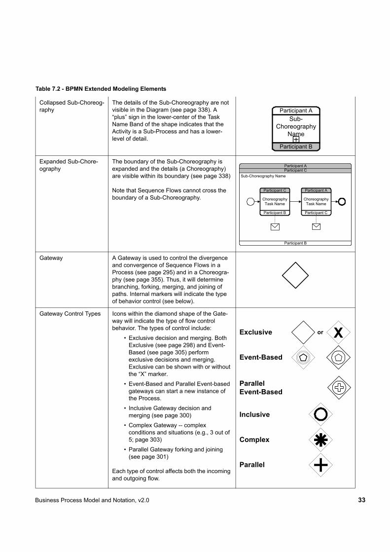
Collapsed Sub-Choreog-raphy
The details of the Sub-Choreography are not visible in the Diagram (see page 338). A “plus” sign in the lower-center of the Task Name Band of the shape indicates that the Activity is a Sub-Process and has a lower-level of detail.
Expanded Sub-Chore-ography
The boundary of the Sub-Choreography is expanded and the details (a Choreography) are visible within its boundary (see page 338)
Note that Sequence Flows cannot cross the boundary of a Sub-Choreography.
Gateway A Gateway is used to control the divergence and convergence of Sequence Flows in a Process (see page 295) and in a Choreogra-phy (see page 355). Thus, it will determine branching, forking, merging, and joining of paths. Internal markers will indicate the type of behavior control (see below).
Gateway Control Types Icons within the diamond shape of the Gate-way will indicate the type of flow control behavior. The types of control include:
• Exclusive decision and merging. Both Exclusive (see page 298) and Event-Based (see page 305) perform exclusive decisions and merging. Exclusive can be shown with or without the “X” marker.
• Event-Based and Parallel Event-based gateways can start a new instance of the Process.
• Inclusive Gateway decision and merging (see page 300)
• Complex Gateway -- complex conditions and situations (e.g., 3 out of 5; page 303)
• Parallel Gateway forking and joining (see page 301)!
Each type of control affects both the incoming and outgoing flow.
Table 7.2 - BPMN Extended Modeling Elements
Sub-Choreography
Name
Participant A
Participant B
Participant B
Participant C
Choreography Task Name
Participant C
Participant A
Choreography Task Name
Sub-Choreography NameParticipant CParticipant A
Participant B
Parallel
Exclusive
Complex
Event-Based
Inclusive
Xor
ParallelEvent-Based
34 Business Process Model and Notation, v2.0
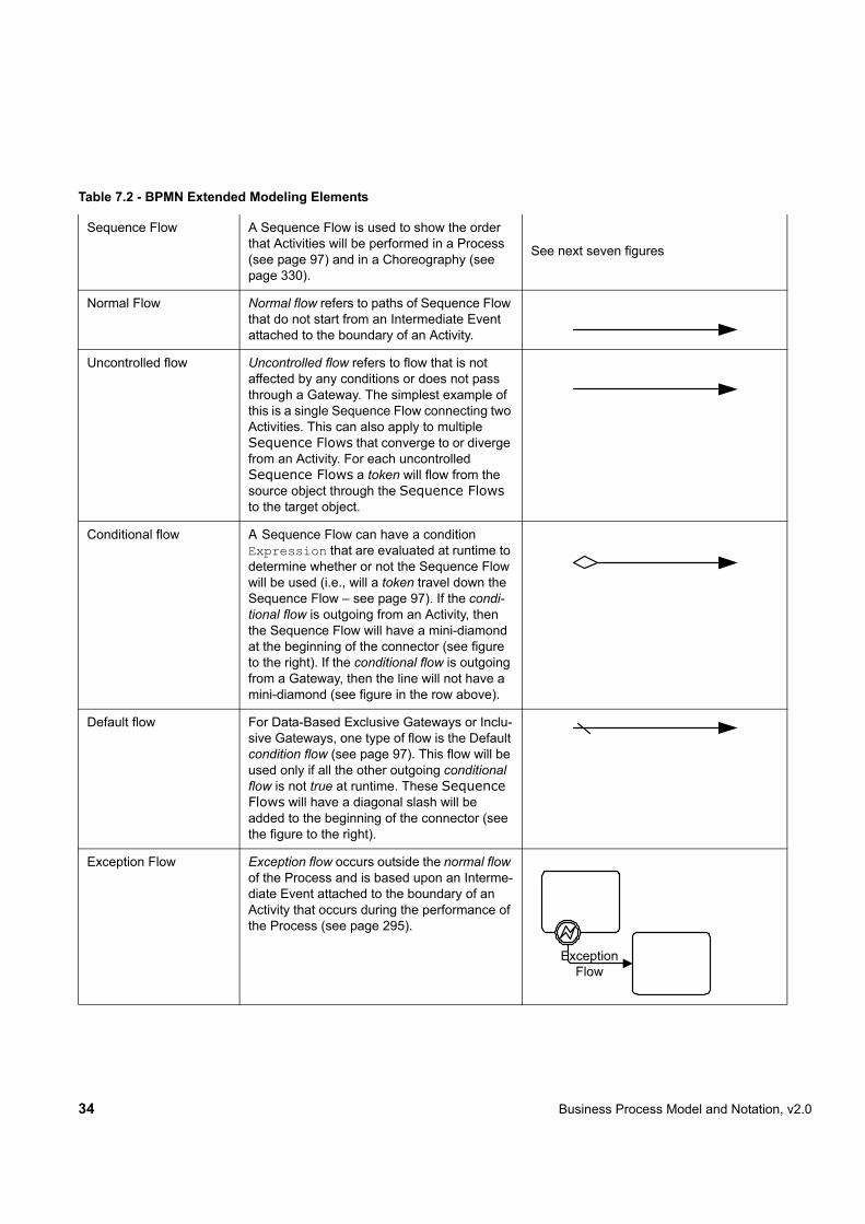
Sequence Flow A Sequence Flow is used to show the order that Activities will be performed in a Process (see page 97) and in a Choreography (see page 330).
See next seven figures
Normal Flow Normal flow refers to paths of Sequence Flow that do not start from an Intermediate Event attached to the boundary of an Activity.
Uncontrolled flow Uncontrolled flow refers to flow that is not affected by any conditions or does not pass through a Gateway. The simplest example of this is a single Sequence Flow connecting two Activities. This can also apply to multiple Sequence Flows that converge to or diverge from an Activity. For each uncontrolled Sequence Flows a token will flow from the source object through the Sequence Flows to the target object.
Conditional flow A Sequence Flow can have a condition Expression that are evaluated at runtime to determine whether or not the Sequence Flow will be used (i.e., will a token travel down the Sequence Flow – see page 97). If the condi-tional flow is outgoing from an Activity, then the Sequence Flow will have a mini-diamond at the beginning of the connector (see figure to the right). If the conditional flow is outgoing from a Gateway, then the line will not have a mini-diamond (see figure in the row above).
Default flow For Data-Based Exclusive Gateways or Inclu-sive Gateways, one type of flow is the Default condition flow (see page 97). This flow will be used only if all the other outgoing conditional flow is not true at runtime. These Sequence Flows will have a diagonal slash will be added to the beginning of the connector (see the figure to the right).
Exception Flow Exception flow occurs outside the normal flow of the Process and is based upon an Interme-diate Event attached to the boundary of an Activity that occurs during the performance of the Process (see page 295).
Table 7.2 - BPMN Extended Modeling Elements
ExceptionFlow
Business Process Model and Notation, v2.0 35
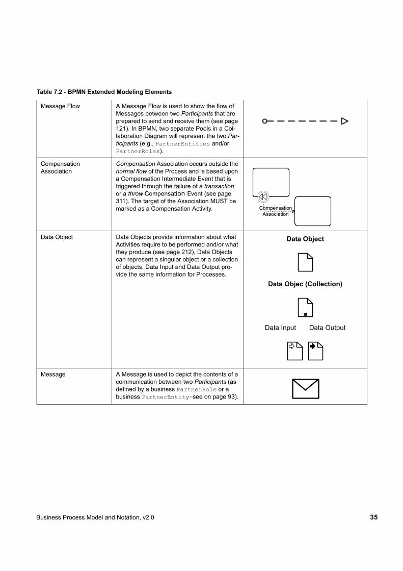
Message Flow A Message Flow is used to show the flow of Messages between two Participants that are prepared to send and receive them (see page 121). In BPMN, two separate Pools in a Col-laboration Diagram will represent the two Par-ticipants (e.g., PartnerEntities and/or PartnerRoles).
Compensation !Association
Compensation Association occurs outside the normal flow of the Process and is based upon a Compensation Intermediate Event that is triggered through the failure of a transaction or a throw Compensation Event (see page 311). The target of the Association MUST be marked as a Compensation Activity.
Data Object Data Objects provide information about what Activities require to be performed and/or what they produce (see page 212), Data Objects can represent a singular object or a collection of objects. Data Input and Data Output pro-vide the same information for Processes.
Data Object
Data Objec (Collection)
Data Input Data Output
Message A Message is used to depict the contents of a communication between two Participants (as defined by a business PartnerRole or a business PartnerEntity—see on page 93).
Table 7.2 - BPMN Extended Modeling Elements
CompensationAssociation
36 Business Process Model and Notation, v2.0
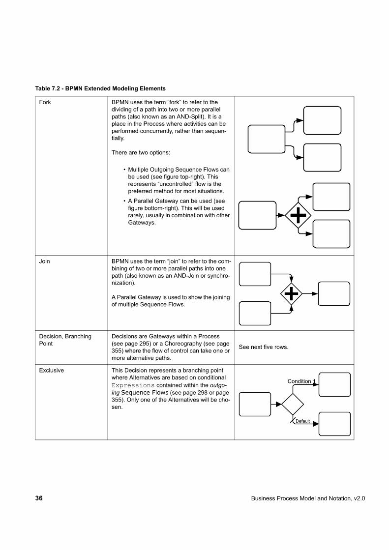
Fork BPMN uses the term “fork” to refer to the dividing of a path into two or more parallel paths (also known as an AND-Split). It is a place in the Process where activities can be performed concurrently, rather than sequen-tially.
There are two options:
• Multiple Outgoing Sequence Flows can be used (see figure top-right). This represents “uncontrolled” flow is the preferred method for most situations.
• A Parallel Gateway can be used (see figure bottom-right). This will be used rarely, usually in combination with other Gateways.
Join BPMN uses the term “join” to refer to the com-bining of two or more parallel paths into one path (also known as an AND-Join or synchro-nization).
A Parallel Gateway is used to show the joining of multiple Sequence Flows.
Decision, Branching Point
Decisions are Gateways within a Process (see page 295) or a Choreography (see page 355) where the flow of control can take one or more alternative paths.
See next five rows.
Exclusive This Decision represents a branching point where Alternatives are based on conditional Expressions contained within the outgo-ing Sequence Flows (see page 298 or page 355). Only one of the Alternatives will be cho-sen.
Table 7.2 - BPMN Extended Modeling Elements
Default
Condition 1
Business Process Model and Notation, v2.0 37
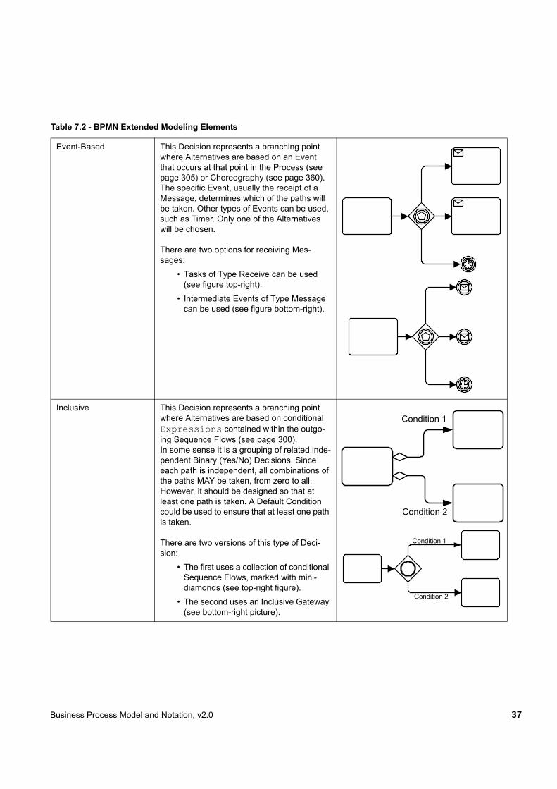
Event-Based This Decision represents a branching point where Alternatives are based on an Event that occurs at that point in the Process (see page 305) or Choreography (see page 360). The specific Event, usually the receipt of a Message, determines which of the paths will be taken. Other types of Events can be used, such as Timer. Only one of the Alternatives will be chosen.
There are two options for receiving Mes-sages:
• Tasks of Type Receive can be used (see figure top-right).
• Intermediate Events of Type Message can be used (see figure bottom-right).
Inclusive This Decision represents a branching point where Alternatives are based on conditional Expressions contained within the outgo-ing Sequence Flows (see page 300).In some sense it is a grouping of related inde-pendent Binary (Yes/No) Decisions. Since each path is independent, all combinations of the paths MAY be taken, from zero to all. However, it should be designed so that at least one path is taken. A Default Condition could be used to ensure that at least one path is taken.
There are two versions of this type of Deci-sion:
• The first uses a collection of conditional Sequence Flows, marked with mini-diamonds (see top-right figure).
• The second uses an Inclusive Gateway (see bottom-right picture).
Table 7.2 - BPMN Extended Modeling Elements
Condition 1
Condition 2
Condition 2
Condition 1
38 Business Process Model and Notation, v2.0
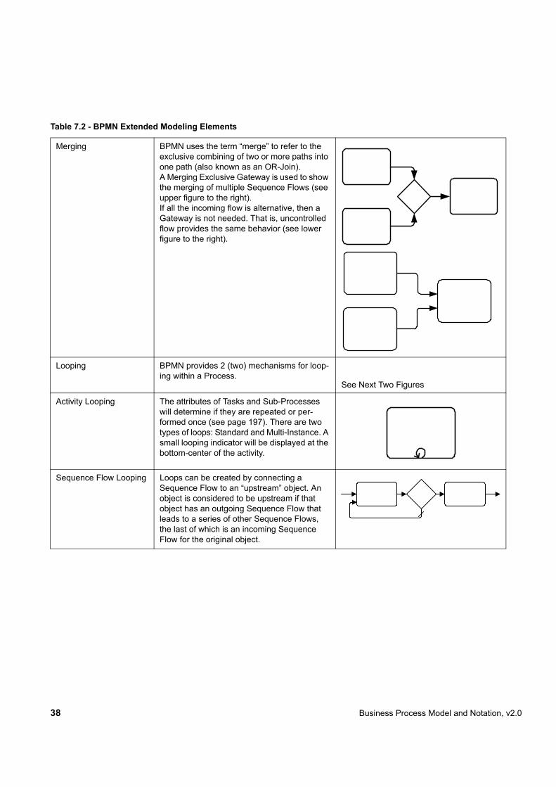
Merging BPMN uses the term “merge” to refer to the exclusive combining of two or more paths into one path (also known as an OR-Join).A Merging Exclusive Gateway is used to show the merging of multiple Sequence Flows (see upper figure to the right).If all the incoming flow is alternative, then a Gateway is not needed. That is, uncontrolled flow provides the same behavior (see lower figure to the right).
Looping BPMN provides 2 (two) mechanisms for loop-ing within a Process.
See Next Two Figures
Activity Looping The attributes of Tasks and Sub-Processes will determine if they are repeated or per-formed once (see page 197). There are two types of loops: Standard and Multi-Instance. A small looping indicator will be displayed at the bottom-center of the activity.
Sequence Flow Looping Loops can be created by connecting a Sequence Flow to an “upstream” object. An object is considered to be upstream if that object has an outgoing Sequence Flow that leads to a series of other Sequence Flows, the last of which is an incoming Sequence Flow for the original object.
Table 7.2 - BPMN Extended Modeling Elements

Business Process Model and Notation, v2.0 39
Multiple Instances The attributes of Tasks and Sub-Processes will determine if they are repeated or per-formed once (see page 198). A set of three (3) horizontal liness will be displayed at the bottom-center of the activity for sequentail Multi-Instances (see upper figure to the right). A set of three (3) vertical liness will be dis-played at the bottom-center of the activity for sequentail Multi-Instances (see lower figure to the right).
Sequential
Parallel
Process Break (some-thing out of the control of the process makes the process pause)
A Process Break is a location in the Process that shows where an expected delay will occur within a Process (see page 257). An Intermediate Event is used to show the actual behavior (see top-right figure). In addition, a Process Break Artifact, as designed by a modeler or modeling tool, can be associated with the Event to highlight the location of the delay within the flow.
Transaction A transaction is a Sub-Process that is sup-ported by a special protocol that insures that all parties involved have complete agreement that the activity should be completed or can-celled (see page 184). The attributes of the activity will determine if the activity is a trans-action. A double-lined boundary indicates that the Sub-Process is a Transaction.
Table 7.2 - BPMN Extended Modeling Elements
Announce Issues for Vote
Voting Response
Increment Tally
40 Business Process Model and Notation, v2.0
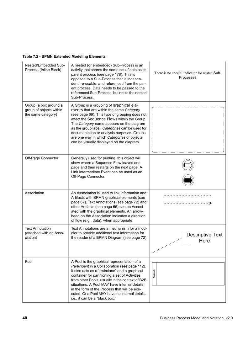
Nested/Embedded Sub-Process (Inline Block)
A nested (or embedded) Sub-Process is an activity that shares the same set of data as its parent process (see page 178). This is opposed to a Sub-Process that is indepen-dent, re-usable, and referenced from the par-ent process. Data needs to be passed to the referenced Sub-Process, but not to the nested Sub-Process.
There is no special indicator for nested Sub-Processes
Group (a box around a group of objects within the same category)
A Group is a grouping of graphical ele-ments that are within the same Category (see page 69). This type of grouping does not affect the Sequence Flows within the Group. The Category name appears on the diagram as the group label. Categories can be used for documentation or analysis purposes. Groups are one way in which Categories of objects can be visually displayed on the diagram.
Off-Page Connector Generally used for printing, this object will show where a Sequence Flow leaves one page and then restarts on the next page. A Link Intermediate Event can be used as an Off-Page Connector.
Association An Association is used to link information and Artifacts with BPMN graphical elements (see page 67). Text Annotations (see page 72) and other Artifacts (see page 66) can be Associ-ated with the graphical elements. An arrow-head on the Association indicates a direction of flow (e.g., data), when appropriate.
Text Annotation (attached with an Asso-ciation)
Text Annotations are a mechanism for a mod-eler to provide additional text information for the reader of a BPMN Diagram (see page 72).
Pool A Pool is the graphical representation of a Participant in a Collaboration (see page 112). It also acts as a “swimlane” and a graphical container for partitioning a set of Activities from other Pools, usually in the context of B2B situations. A Pool MAY have internal details, in the form of the Process that will be exe-cuted. Or a Pool MAY have no internal details, i.e., it can be a "black box."
Table 7.2 - BPMN Extended Modeling Elements
Descriptive Text Here
Nam
e
Business Process Model and Notation, v2.0 41
7.3 BPMN Diagram TypesThe BPMN 2.0 aims to cover three basic models of Processes: private Processes (both executable and non-executable), public Processes, and Choreographies. Within and between these three BPMN sub-models, many types of Diagrams can be created. The following are examples of Business Processes that can be modeled using BPMN 2.0:
• High-level non-executable Process Activities (not functional breakdown)• Detailed executable Business Process• As-is or old Business Process• To-be or new Business Process• A description of expected behavior between two (2) or more business Participants—a Choreography.• Detailed private Business Process (either executable or non-executable) with interactions to one or more external
Entities (or “Black Box” Processes)• Two or more detailed executable Processes interacting• Detailed executable Business Process relationship to a Choreography• Two or more public Processes• Public Process relationship to Choreography• Two or more detailed executable Business Processes interacting through a Choreography
BPMN is designed to allow describing all above examples of Business Processes. However, the ways that different sub-models are combined is left to tool vendors. A BPMN 2.0 compliant implementation could RECOMMEND that modelers pick a focused purpose, such as a private Process, or Choreographies. However, the BPMN 2.0 specification makes no assumptions.
7.4 Use of Text, Color, Size, and Lines in a Diagram Text Annotation objects can be used by the modeler to display additional information about a Process or attributes of the objects within a BPMN Diagram.
!"BPMN elements (e.g. Flow objects) MAY have labels (e.g., its name and/or other attributes) placed inside the shape, or above or below the shape, in any direction or location, depending on the preference of the modeler or modeling tool vendor.
!"The fills that are used for the graphical elements MAY be white or clear.
!"The notation MAY be extended to use other fill colors to suit the purpose of the modeler or tool (e.g., to highlight the value of an object attribute). However,
!"The markers for “throwing” Events MUST have a dark fill (see “End Event” on page 253 and “Intermediate
Lanes A Lane is a sub-partition within a Pool and will extend the entire length of the Pool, either vertically or horizontally (see on page 313). Lanes are used to organize and categorize Activities.
Table 7.2 - BPMN Extended Modeling Elements
Nam
e Nam
eN
ame

42 Business Process Model and Notation, v2.0
Event” on page 257 for more details).
!"Participant Bands for Choreography Tasks and Sub-Choreographies that are not the initiator of the Activity MUST have a light fill (see “Choreography Task” on page 333 and “Sub-Choreography” on page 338 for more details).
!"Flow objects and markers MAY be of any size that suits the purposes of the modeler or modeling tool.
!"The lines that are used to draw the graphical elements MAY be black.
!"The notation MAY be extended to use other line colors to suit the purpose of the modeler or tool (e.g., to highlight the value of an object attribute).
!"The notation MAY be extended to use other line styles to suit the purpose of the modeler or tool (e.g., to highlight the value of an object attribute) with the condition that the line style MUST NOT conflict with any current BPMN defined line style. Thus, the line styles of Sequence Flows, Message Flows, and Text Associations MUST NOT be modified or duplicated.
7.5 Flow Object Connection RulesAn incoming Sequence Flow can connect to any location on a Flow Object (left, right, top, or bottom). Likewise, an outgoing Sequence Flow can connect from any location on a Flow Object (left, right, top, or bottom). A Message Flow also has this capability. BPMN allows this flexibility; however, we also RECOMMEND that modelers use judgment or best practices in how Flow Objects should be connected so that readers of the Diagrams will find the behavior clear and easy to follow. This is even more important when a Diagram contains Sequence Flows and Message Flows. In these situations it is best to pick a direction of Sequence Flows, either left to right or top to bottom, and then direct the Message Flows at a 90° angle to the Sequence Flows. The resulting Diagrams will be much easier to understand.
7.5.1 Sequence Flow Connections Rules
Table 7.3 displays the BPMN Flow Objects and shows how these objects can connect to one another through Sequence Flows. These rules apply to the connections within a Process Diagram and within a Choreography Diagram. The # symbol indicates that the object listed in the row can connect to the object listed in the column. The quantity of connections into and out of an object is subject to various configuration dependencies are not specified here. Refer to the sections in the next chapter for each individual object for more detailed information on the appropriate connection rules. Note that if a Sub-Process has been expanded within a Diagram, the objects within the Sub-Process cannot be connected to objects outside of the Sub-Process. Nor can Sequence Flows cross a Pool boundary.
Table 7.3 – Sequence Flow Connection Rules
From\To
‰ # # # #
Business Process Model and Notation, v2.0 43
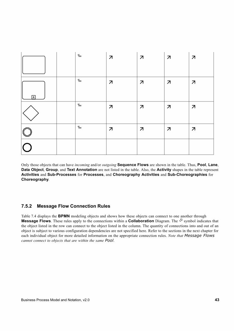
Only those objects that can have incoming and/or outgoing Sequence Flows are shown in the table. Thus, Pool, Lane, Data Object, Group, and Text Annotation are not listed in the table. Also, the Activity shapes in the table represent Activities and Sub-Processes for Processes, and Choreography Activities and Sub-Choreographies for Choreography.
7.5.2 Message Flow Connection Rules
Table 7.4 displays the BPMN modeling objects and shows how these objects can connect to one another through Message Flows. These rules apply to the connections within a Collaboration Diagram. The $ symbol indicates that the object listed in the row can connect to the object listed in the column. The quantity of connections into and out of an object is subject to various configuration dependencies are not specified here. Refer to the sections in the next chapter for each individual object for more detailed information on the appropriate connection rules. Note that Message Flows cannot connect to objects that are within the same Pool.
‰ # # # #
‰ # # # #
‰ # # # #
‰ # # # #

44 Business Process Model and Notation, v2.0
Only those objects that can have incoming and/or outgoing Message Flows are shown in the table. Thus, Lane, Gateway, Data Object, Group, and Text Annotation are not listed in the table.
7.6 BPMN ExtensibilityBPMN 2.0 introduces an extensibility mechanism that allows extending standard BPMN elements with additional attributes. It can be used by modelers and modeling tools to add non-standard elements or Artifacts to satisfy a specific need, such as the unique requirements of a vertical domain, and still have valid BPMN Core. Extension attributes MUST NOT contradict the semantics of any BPMN element. In addition, while extensible, BPMN Diagrams should still have the basic look-and-feel so that a Diagram by any modeler should be easily understood by any viewer of the Diagram. Thus the footprint of the basic flow elements (Events, Activities, and Gateways) MUST NOT be altered.
Table 7.4 – Message Flow Connection Rules
From\To
ˆ $ $ $ $
ˆ $ $ $ $
ˆ $ $ $ $
ˆ $ $ $ $
ˆ $ $ $ $
Nam
e Pool
Nam
e Pool

Business Process Model and Notation, v2.0 45
The specification differentiates between mandatory and optional extensions (Section 8.2.3 explains the syntax used to declare extensions). If a mandatory extension is used, a compliant implementation MUST understand the extension. If an optional extension is used, a compliant implementation MAY ignore the extension.
7.7 BPMN ExampleThe following is an example of a manufacturing process from different perspectives.
Figure 7.6 - An example of a Collaboration diagram with black-box Pools
OrderConfirmation
RejectionShipment
PartsProvisioning
OpenAuction
Customer
Manufacturer
Supplier Bidder
46 Business Process Model and Notation, v2.0
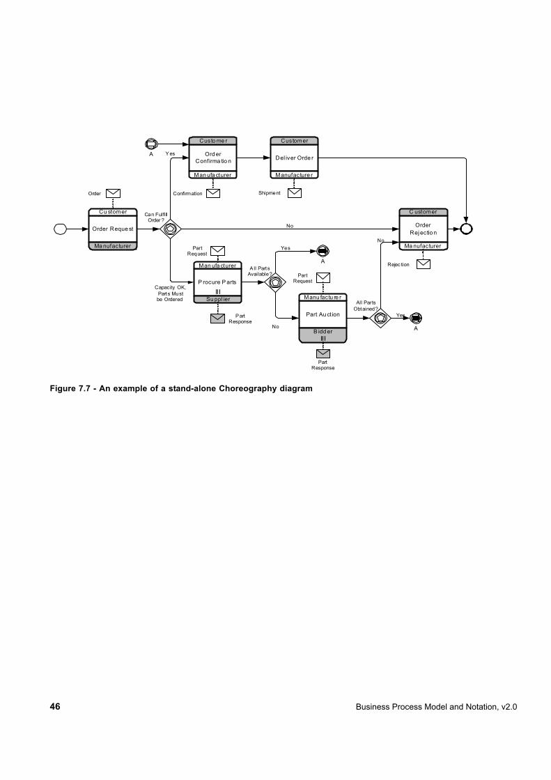
Figure 7.7 - An example of a stand-alone Choreography diagram
Order Reque st
Cu stomer
Ma nufacturer
Ord er Confirma tio n
Custo me r
Man ufa cturer
Order Rejectio n
C ustomer
Ma nufacturer
Del iver Orde r
Customer
Manufacture r
P rocure P arts
Man ufa cturer
Su ppl ier
Y es
Can FulfillOrder ?
No
Capacity OK, Parts Mustbe Ordered
A
A
Yes
No A
YesPart Au ction
Manu factu re r
B idd er
No
Order Confirmation
Rejec tion
PartRequest
PartResponse
PartRequest
PartResponse
A ll Part sAvailable?
All PartsObtained?
Shipment

Business Process Model and Notation, v2.0 47
Figure 7.8 - An example of a stand-alone Process (Orchestration) diagram

48 Business Process Model and Notation, v2.0


![QCL_14_v3_[flowcharting]_[banasthali vidyapith]_[komal sharma]](https://img.pdfslide.us/doc/110x75/55a7d44a1a28ab780f8b487a/qcl14v3flowchartingbanasthali-vidyapithkomal-sharma.jpg)