Embed Size (px)
Citation preview
8/11/2019 7 L-Eqos_mrg
http://slidepdf.com/reader/full/7-l-eqosmrg 1/94
C H A P T E R
41-1
Software Configuration Guide—Release IOS XE 3.4.0SG and IOS 15.1(2)SG
OL-27597-01
41
Configuring Quality of Service
This chapter describes how to configure quality of service (QoS) with either automatic QoS (auto-QoS)
commands or standard QoS commands on a Catalyst 4500 Series Switch. It describes how to specify
QoS configuration on different types of interfaces (access, Layer 2 trunk, Layer 3 routed, Etherchannel)
as well as VLANs. It also describes how to specify different QoS configurations on different VLANs on
a given interface (per-port per-VLAN QoS).
A switch supports a QoS configuration model known as MQC (Modular QoS CLI). Please refer to the
appropriate configuration section for the supervisor engine on which QoS will be configured. For more
information about MQC, see the “Modular Quality of Service Command-Line Interface" section of the
Cisco IOS Quality of Service Solutions Configuration Guide, Release 12.3.
This chapter addresses both VSS and non-VSS environments. Sections include:
• Overview of QoS, page 41-2
• Configuring VSS QoS, page 41-13
• Configuring QoS on a Standalone Supervisor Engine 6-E/6L-E or Supervisor Engine 7-E/7L-E,
page 41-47
• Configuring VSS Auto-QoS, page 41-81
• Configuring Auto-QoS on a Standalone Supervisor Engine 6-E/6L-E or Supervisor Engine
7-E/7L-E, page 41-86
Note For complete syntax and usage information for the switch commands used in this chapter, first look at
the Cisco Catalyst 4500 Series Switch Command Reference and related publications at this location:
http://www.cisco.com/en/US/products//hw/switches/ps4324/index.html
If the command is not found in the Catalyst 4500 Series Switch Command Reference, it will be found in
the larger Cisco IOS library. Refer to the Cisco IOS Command Reference and related publications at this
location:
http://www.cisco.com/en/US/products/ps6350/index.html

8/11/2019 7 L-Eqos_mrg
http://slidepdf.com/reader/full/7-l-eqosmrg 2/94
41-2
Software Configuration Guide—Release IOS XE 3.4.0SG and IOS 15.1(2)SG
OL-27597-01
Chapter 41 Configuring Quality of Service
Overview of QoS
Overview of QoSTypically, networks operate on a best-effort delivery basis, which means that all traffic has equal priority
and an equal chance of being delivered in a timely manner. When congestion occurs, all traffic has an
equal chance of being dropped.
QoS selects network traffic (both unicast and multicast), prioritizes it according to its relative
importance, and uses congestion avoidance to provide priority-indexed treatment; QoS can also limit the
bandwidth used by network traffic. QoS can make network performance more predictable and bandwidth
utilization more effective.
This section contains the following subsections:
• Prioritization, page 41-2
• QoS Terminology, page 41-3
• Basic QoS Model, page 41-5
• Classification, page 41-6
• Policing and Marking, page 41-8
• Queueing and Scheduling, page 41-8
• Packet Modification, page 41-9
• Per Port Per VLAN QoS, page 41-10
• Flow-based QoS, page 41-10
• Using Metadata in QoS Policy, page 41-11
Prioritization
QoS implementation is based on the DiffServ architecture. This architecture specifies that each packet
is classified upon entry into the network. The classification is carried in the IP packet header, using 6bits from the deprecated IP type of service (TOS) field to carry the classification (class) information.
Classification can also be carried in the Layer 2 frame. These special bits in the Layer 2 frame or
a Layer 3 packet are described here and shown in Figure 41-1:
• Prioritization values in Layer 2 frames:
Layer 2 Inter-Switch Link (ISL) frame headers have a 1-byte User field that carries an IEEE 802.1p
class of service (CoS) value in the three least-significant bits. On interfaces configured as Layer 2
ISL trunks, all traffic is in ISL frames.
Layer 2 802.1Q frame headers have a 2-byte Tag Control Information field that carries the CoS value
in the three most-significant bits, which are called the User Priority bits. On interfaces configured
as Layer 2 802.1Q trunks, all traffic is in 802.1Q frames except for traffic in the native VLAN.
Other frame types cannot carry Layer 2 CoS values.Layer 2 CoS values range from 0 for low priority to 7 for high priority.
• Prioritization bits in Layer 3 packets:
Layer 3 IP packets can carry either an IP precedence value or a Differentiated Services Code Point
(DSCP) value. QoS supports the use of either value because DSCP values are backward-compatible
with IP precedence values.
IP precedence values range from 0 to 7.

8/11/2019 7 L-Eqos_mrg
http://slidepdf.com/reader/full/7-l-eqosmrg 3/94
41-3
Software Configuration Guide—Release IOS XE 3.4.0SG and IOS 15.1(2)SG
OL-27597-01
Chapter 41 Configuring Quality of Service
Overview of QoS
DSCP values range from 0 to 63.
Figure 41-1 QoS Classification Layers in Frames and Packets
All switches and routers across the Internet rely on the class information to provide the same forwarding
treatment to packets with the same class information and different treatment to packets with different
class information. The class information in the packet can be assigned by end hosts or by switches or
routers along the way, based on a configured policy, detailed examination of the packet, or both. Detailed
examination of the packet is expected to happen closer to the edge of the network so that the coreswitches and routers are not overloaded.
Switches and routers along the path can use the class information to limit the amount of resources
allocated per traffic class. The behavior of an individual device when handling traffic in the DiffServ
architecture is called per-hop behavior. If all devices along a path provide a consistent per-hop behavior,
you can construct an end-to-end QoS solution.
Implementing QoS in your network can be a simple or complex task and depends on the QoS features
offered by your internetworking devices, the traffic types and patterns in your network, and the
granularity of control you need over incoming and outgoing traffic.
QoS Terminology
The following terms are used when discussing QoS features:
• Packets carry traffic at Layer 3.
• Frames carry traffic at Layer 2. Layer 2 frames carry Layer 3 packets.
6 8 1 4 0
Encapsulated Packet
Layer 2header
IP header
3 bits used for CoS
Data
Layer 2 ISL Frame
ISL header(26 bytes)
Encapsulated frame ...FCS
(4 bytes)
Layer 2 802.1Q/P Frame
PreambleStart frame
delimiter
DA
Len
SA Tag PT Data FCS
Layer 3 IPv4 Packet
Versionlength
ToS(1 byte)
ID Offset TTL Proto FCS IP-SA IP-DA Data
3 bits used for CoS (user priority)
IP precedence or DSCP

8/11/2019 7 L-Eqos_mrg
http://slidepdf.com/reader/full/7-l-eqosmrg 4/94
41-4
Software Configuration Guide—Release IOS XE 3.4.0SG and IOS 15.1(2)SG
OL-27597-01
Chapter 41 Configuring Quality of Service
Overview of QoS
• Labels are prioritization values carried in Layer 3 packets and Layer 2 frames:
– Layer 2 class of service (CoS) values, which range between zero for low priority and seven for
high priority:
Layer 2 Inter-Switch Link (ISL) frame headers have a 1-byte User field that carries an IEEE
802.1p CoS value in the three least significant bits.
Layer 2 802.1Q frame headers have a 2-byte Tag Control Information field that carries the CoS
value in the three most significant bits, which are called the User Priority bits.
Other frame types cannot carry Layer 2 CoS values.
Note On interfaces configured as Layer 2 ISL trunks, all traffic is in ISL frames. On interfaces
configured as Layer 2 802.1Q trunks, all traffic is in 802.1Q frames except for traffic in the
native VLAN.
– Layer 3 IP precedence values—The IP version 4 specification defines the three most significant
bits of the 1-byte ToS field as IP precedence. IP precedence values range between zero for low
priority and seven for high priority.
– Layer 3 differentiated services code point (DSCP) values—The Internet Engineering Task
Force (IETF) has defined the six most significant bits of the 1-byte IP ToS field as the DSCP.
The per-hop behavior represented by a particular DSCP value is configurable. DSCP values
range between 0 and 63.
Note Layer 3 IP packets can carry either an IP precedence value or a DSCP value. QoS supports
the use of either value, since DSCP values are backwards compatible with IP precedence
values. See Table 41-1.
Table 41-1 IP Precedence and DSCP Values
3-bit IPPrecedence
6 MSb1 of ToS 6-bitDSCP
3-bit IPPrecedence
6 MSb1 of ToS 6-bitDSCP
8 7 6 5 4 3 8 7 6 5 4 3
0 0
0
0
0
0
0
0
0
0
0
0
0
0
0
0
0
0
0
0
0
0
0
0
0
0
0
0
0
1
1
1
1
0
0
1
1
0
0
1
1
0
1
0
1
0
1
0
1
0
1
2
3
4
5
6
7
4 1
1
1
1
1
1
1
1
0
0
0
0
0
0
0
0
0
0
0
0
0
0
0
0
0
0
0
0
1
1
1
1
0
0
1
1
0
0
1
1
0
1
0
1
0
1
0
1
32
33
34
35
36
37
38
39
1 0
00
0
0
0
0
0
0
00
0
0
0
0
0
1
11
1
1
1
1
1
0
00
0
1
1
1
1
0
01
1
0
0
1
1
0
10
1
0
1
0
1
8
910
11
12
13
14
15
5 1
11
1
1
1
1
1
0
00
0
0
0
0
0
1
11
1
1
1
1
1
0
00
0
1
1
1
1
0
01
1
0
0
1
1
0
10
1
0
1
0
1
40
4142
43
44
45
46
47

8/11/2019 7 L-Eqos_mrg
http://slidepdf.com/reader/full/7-l-eqosmrg 5/94
41-5
Software Configuration Guide—Release IOS XE 3.4.0SG and IOS 15.1(2)SG
OL-27597-01
Chapter 41 Configuring Quality of Service
Overview of QoS
• Classification is the selection of traffic to be marked.
• Marking, according to RFC 2475, is the process of setting a Layer 3 DSCP value in a packet; in this
publication, the definition of marking is extended to include setting Layer 2 CoS values.
• Policing is limiting bandwidth used by a flow of traffic. Policing can mark or drop traffic.
Basic QoS ModelFigure 41-2 illustrates a high-level flow of QoS function.
Figure 41-2 QoS Packet Processing
2 0
00
0
0
0
0
0
1
11
1
1
1
1
1
0
00
0
0
0
0
0
0
00
0
1
1
1
1
0
01
1
0
0
1
1
0
10
1
0
1
0
1
16
1718
19
20
21
22
23
6 1
11
1
1
1
1
1
1
11
1
1
1
1
1
0
00
0
0
0
0
0
0
00
0
1
1
1
1
0
01
1
0
0
1
1
0
10
1
0
1
0
1
48
4950
51
52
53
54
55
3 0
0
0
0
0
0
0
0
1
1
1
1
1
1
1
1
1
1
1
1
1
1
1
1
0
0
0
0
1
1
1
1
0
0
1
1
0
0
1
1
0
1
0
1
0
1
0
1
24
25
26
27
28
29
30
31
7 1
1
1
1
1
1
1
1
1
1
1
1
1
1
1
1
1
1
1
1
1
1
1
1
0
0
0
0
1
1
1
1
0
0
1
1
0
0
1
1
0
1
0
1
0
1
0
1
56
57
58
59
60
61
62
63
1. MSb = most significant bit
Table 41-1 IP Precedence and DSCP Values (continued)
3-bit IPPrecedence
6 MSb1 of ToS 6-bitDSCP
3-bit IPPrecedence
6 MSb1 of ToS 6-bitDSCP
8 7 6 5 4 3 8 7 6 5 4 3
PacketReception
Input
Output
Input QoSClassification
InputPolicing
and Marking
ForwardingLookup
Output QoSClassification
OutputPolicing
and Marking
Active QueueManagement
Port/QueueScheduling(Sharing/ Shaping)
PacketTransmission
2 0 3 9 7 3

8/11/2019 7 L-Eqos_mrg
http://slidepdf.com/reader/full/7-l-eqosmrg 6/94
41-6
Software Configuration Guide—Release IOS XE 3.4.0SG and IOS 15.1(2)SG
OL-27597-01
Chapter 41 Configuring Quality of Service
Overview of QoS
The QoS model proceeds as follows:
Step 1 The incoming packet is classified (based on different packet fields, receive port and/or VLAN) to belong
to a traffic class.
Step 2 Depending on the traffic class, the packet is rate-limited/policed and its priority is optionally marked
(typically at the edge of the network) so that lower priority packets are dropped or marked with lowerpriority in the packet fields (DSCP and CoS).
Step 3 After the packet has been marked, it is looked up for forwarding. This action obtains the transmit port
and VLAN to transmit the packet.
Step 4 The packet is classified in the output direction based on the transmit port and/or VLAN. The
classification takes into account any marking of the packet by input QoS.
Step 5 Depending on the output classification, the packet is policed, its priority is optionally (re-)marked , and
the transmit queue for the packet is determined depending on the traffic class.
Step 6 The transmit queue state is dynamically monitored via the AQM (Active Queue Management) algorithm
and drop threshold configuration to determine whether the packet should be dropped or enqueued for
transmission.
Step 7 If eligible for transmission, the packet is enqueued to a transmit queue. The transmit queue is selected
based on output QoS classification criteria. The selected queue provides the desired behavior in terms
of latency and bandwidth.
Classification
Classification is the process of distinguishing one kind of traffic from another by examining the fields
in the packet. Classification is enabled when a QoS policy-map is attached to an interface.
You specify which fields in the frame or packet that you want to use to classify incoming traffic.
For non-IP traffic, you have the following classification options:
• CoS value in the VLAN tag of the incoming frame is used to classify the packet.
• If the frame does not contain a CoS value, the port's default CoS value ("0") is used for the
classification.
Perform the classification based on a configured MAC ACL, which examines the fields in the Layer
2 header.
For IP traffic, you have the following classification options:
• IP DSCP or IP Precedence in the incoming packet is used for classification. DSCP values range from
0 to 63.
• Perform the classification based on a configured IP standard or extended ACL, which examines
various fields in the IP header.
Classification Based on QoS ACLs
A packet can be classified for QoS using multiple match criteria, and the classification can specify
whether the packet should match all of the specified match criteria or at least one of the match criteria.
To define a QoS classifier, you can provide the match criteria using the match statements in a class map.

8/11/2019 7 L-Eqos_mrg
http://slidepdf.com/reader/full/7-l-eqosmrg 7/94
41-7
Software Configuration Guide—Release IOS XE 3.4.0SG and IOS 15.1(2)SG
OL-27597-01
Chapter 41 Configuring Quality of Service
Overview of QoS
In the 'match' statements, you can specify the fields in the packet to match on, or you can use IP standard
or IP extended ACLs or MAC ACLs. For more information, see the “Classification Based on Class Maps
and Policy Maps” section on page 41-7.
If the class map is configured to match all the match criteria, then a packet must satisfy all the match
statements in the class map before the QoS action is taken. The QoS action for the packet is not taken if
the packet does not match even one match criterion in the class map.If the class map is configured to match at least one match criterion, then a packet must satisfy at least
one of the match statements in the class map before the QoS action is taken. The QoS action for the
packet is not taken if the packet does not match any match criteria in the class map.
Note When you use the IP standard and IP extended ACLs, the permit and deny ACEs in the ACL have a
slightly different meaning in the QoS context.
• If a packet encounters (and satisfies) an ACE with a “permit,” then the packet “matches” the match
criterion in the QoS classification.
• If a packet encounters (and satisfies) an ACE with a “deny,” then the packet “does not match” the
match criterion in the QoS classification.
• If no match with a permit action is encountered and all the ACEs have been examined, then the
packet “does not match” the criterion in the QoS classification.
Note When creating an access list, remember that, by default, the end of the access list contains an implicit
deny statement for everything if it did not find a match before reaching the end.
After a traffic class has been defined with the class map, you can create a policy that defines the QoS
actions for a traffic class. A policy might contain multiple classes with actions specified for each one of
them. A policy might include commands to classify the class as a particular aggregate (for example,
assign a DSCP) or rate limit the class. This policy is then attached to a particular port on which it
becomes effective.You implement IP ACLs to classify IP traffic by using the access-list global configuration command.
When a class-map is created with the match-all keyword, you cannot include both IP and MAC ACLs
as match criteria.
Classification Based on Class Maps and Policy Maps
A class map is a mechanism that you use to isolate and name a specific traffic flow (or class) from all
other traffic. The class map defines the criterion used to match against a specific traffic flow to further
classify it; the criteria can include matching the access group defined by the ACL or matching a specific
list of DSCP, IP precedence, or L2 CoS values. If you have more than one type of traffic that you want
to classify, you can create another class map and use a different name. After a packet is matched against
the class-map criteria, you can specify the QoS actions via a policy map.
A policy map specifies the QoS actions for the traffic classes. Actions can include setting a specific CoS,
DSCP, or IP precedence value; policing the traffic to a specified rate; specifying the traffic bandwidth
limitations; shaping the traffic to a specified rate. Before a policy map can be effective, you must attach
it to an interface.
You create a class map by using the class-map global configuration command. When you enter the
class-map command, the switch enters the class-map configuration mode. In this mode, you define the
match criteria for the traffic by using the match class-map configuration command.

8/11/2019 7 L-Eqos_mrg
http://slidepdf.com/reader/full/7-l-eqosmrg 8/94
41-8
Software Configuration Guide—Release IOS XE 3.4.0SG and IOS 15.1(2)SG
OL-27597-01
Chapter 41 Configuring Quality of Service
Overview of QoS
You create and name a policy map by using the policy-map global configuration command. When you
enter this command, the switch enters the policy-map configuration mode. In this mode, you specify the
actions to take on a specific traffic class by using the set, police, bandwidth, or shape policy-map
configuration and policy-map class configuration commands. To make the policy map effective, you
attach it to an interface by using the service-policy interface configuration command.
The policy map can also contain commands that define the policer, (the bandwidth limitations of thetraffic) and the action to take if the limits are exceeded. For more information, see the “Policing and
Marking” section on page 41-8.
A policy map also has these characteristics:
• A policy map can contain up to 254 class statements.
• You can have different classes within a policy map.
Policing and Marking
Policing involves creating a policer that specifies the bandwidth limits for the traffic. Packets that exceed
the limits are out of profile or nonconforming. Each policer specifies the action to take for packets that
are in or out of profile. These actions, carried out by the marker, include passing through the packet
without modification, dropping the packet, or marking down the packet with a new DSCP value that is
obtained from the configurable policed-DSCP map. You can configure policer within a policy map with
the police command in policy-map class configuration mode. For information on the policed-DSCP map,
see the “Queueing and Scheduling” section on page 41-8.
When configuring policing and policers, keep these items in mind:
• Policers account only for the Layer 2 header length when calculating policer rates. In contrast,
shapers account for header length as well as IPG in rate calculations.
• Beginning with Cisco IOS Release 15.0(2)SG (IOS XE 3.2.0), Supervisor Engine 6-E, Supervisor
Engine 6L-E, Catalyst 4900M, Catalyst 4948E, Supervisor Engine 7-E, and Supervisor Engine 7L-E
support the qos account layer-all encapsulation command, which accounts for Layer 1 headers of
20 bytes (12 bytes preamble + 8 bytes IPG) and Layer 2 headers in policing features.
• Only the average rate and committed burst parameters are configurable.
• After you configure the policy map and policing actions, attach the policy to an ingress or egress
interface by using the service-policy interface configuration command.
• For 2 rate 3 colors (2r3c) policers, if no explicit violation-action is specified, the exceed-action is
used as the violate-action.
Queueing and Scheduling
The Catalyst 4500 Series Switch supports 8 transmit queues per port. Once the decision has been made
to forward a packet out a port, the output QoS classification determines the transmit queue into whichthe packet must be enqueued.
Queues are assigned when an output policy attached to a port with one or more queuing related actions
for one or more classes of traffic. Because there are only eight queues per port, there are at most eight
traffic classes (including class-default, the reserved class) with queuing action(s). Classes of traffic that
do not have any queuing action are referred to as non-queuing classes. Non-queuing class traffic use the
queue corresponding to class-default .

8/11/2019 7 L-Eqos_mrg
http://slidepdf.com/reader/full/7-l-eqosmrg 9/94
41-9
Software Configuration Guide—Release IOS XE 3.4.0SG and IOS 15.1(2)SG
OL-27597-01
Chapter 41 Configuring Quality of Service
Overview of QoS
Active Queue Management
Active queue management (AQM) is the pro-active approach of informing you about congestion before
a buffer overflow occurs. AQM is done using Dynamic buffer limiting (DBL). DBL tracks the queue
length for each traffic flow in the switch. When the queue length of a flow exceeds its limit, DBL drop
packets.
Sharing Link Bandwidth Among Transmit Queues
The eight transmit queues for a transmit port share the available link bandwidth of that transmit port.
You can set the link bandwidth to be shared differently among the transmit queues using the
bandwidth command in the policy-map class configuration command in class mode.
With this command, you assign the minimum guaranteed bandwidth for each transmit queue.
By default, all queues are scheduled in a round robin manner.
Strict Priority / Low Latency Queueing
You can only configure one transmit queue on a port as strict priority (termed Low Latency Queue, or
LLQ).
LLQ provides strict-priority queuing for a traffic class. It enables delay-sensit ive data, such as voice, to
be sent before packets in other queues. The priority queue is serviced first until it is empty or until it falls
under r its shape rate. Only one traffic stream can be destined for the priority queue per class-level policy.
You enable the priority queue for a traffic class with the priority policy-map class configuration
command in class mode.
Traffic Shaping
Traffic Shaping provides the ability to control the rate of outgoing traffic in order to make sure that the
traffic conforms to the maximum rate of transmission contracted for it. Traffic that meets certain profilecan be shaped to meet the downstream traffic rate requirements to handle any data rate mismatches.
Each transmit queue can be configured to transmit a maximum rate using the shape command in the
policy-map class configuration command in class mode
The configuration allows you to specify the maximum rate of traffic. Any traffic that exceeds the
configured shape rate is queued and transmitted at the configured rate. If the burst of traffic exceeds the
size of the queue, packets are dropped to maintain transmission at the configured shape rate.
Packet Modification
A packet is classified, policed, and queued to provide QoS. Packet modifications can occur during this
process:
• For IP packets, classification involves assigning a DSCP to the packet. However, the packet is not
modified at this stage; only an indication of the assigned DSCP is carried along. The reason for this
is that QoS classification and ACL lookup occur in parallel, and it is possible that the ACL specifies
that the packet should be denied and logged. In this situation, the packet is forwarded with its
original DSCP to the CPU, where it is again processed through ACL software.

8/11/2019 7 L-Eqos_mrg
http://slidepdf.com/reader/full/7-l-eqosmrg 10/94
41-10
Software Configuration Guide—Release IOS XE 3.4.0SG and IOS 15.1(2)SG
OL-27597-01
Chapter 41 Configuring Quality of Service
Overview of QoS
• For non-IP packets, classification involves assigning an internal DSCP to the packet, but because
there is no DSCP in the non-IP packet, no overwrite occurs. Instead, the internal DSCP is used both
for queueing and schedul ing decisions and for writing the CoS priority value in the tag if the packet
is being transmitted on either an ISL or 802.1Q trunk port.
• During policing, IP and non-IP packets can have another DSCP assigned to them (if they are out of
profile and the policer specifies a markdown DSCP). Once again, the DSCP in the packet is notmodified, but an indication of the marked-down value is carried along. For IP packets, the packet
modification occurs at a later stage.
Per Port Per VLAN QoS
Per-port per-VLAN QoS (PVQoS) offers differentiated quality-of-services to individual VLANs on a
trunk port. It enables service providers to rate limit individual VLAN-based services on each trunk port
to a business or a residence. In an enterprise Voice-over-IP environment, it can be used to rate limit voice
VLAN even if an attacker impersonates an IP phone. A per-port per-VLAN service policy can be
separately applied to either ingress or egress traffic. For configuration details see “Enabling Per-Port
Per-VLAN QoS” section on page 41-70.
Flow-based QoS
Note Before reading this section, you should be familiar with implementing Flexible NetFlow (Chapter 63,
“Configuring Flexible NetFlow”) and QoS implementation in this chapter.
Flow based QoS enables microflow policing and marking capability to dynamically learn traffic flows.
It also rate limits each unique flow to an individual rate. Flow based QoS is available on a Catalyst 4500
Series Switch with the built-in NetFlow hardware support. It can be applied to ingress traffic on both
switched and routed interfaces with flow masks defined using Flexible NetFlow (FNF). It supports up to
100,000 individual flows in hardware and up to 512 unique policer configuration. Flow based QoS is
typically used in environments where per-user, granular rate-limiting required. For example, per-flow
outbound and inbound traffic rate might differ. Flow based QoS is also referred to as User Based Rate
Limiting (UBRL).
A flow is defined as a stream of packets having the same properties as those defined by the key fields in
the FNF flow record. A new flow is created when the value of data in packet’s key fields is unique with
respect to the flow that already exist.
A flow based QoS policy is possesses one or more classmaps matching on a FNF flow record. Such a
classmap must be configured as match-all to match all the match criteria specified in the classmap.
When a flow based QoS policy is attached to a QoS target, ingress traffic on the target is first classified
based on the classification rules specified in the class-map. If the classifier has FNF flow record, the
key fields specified in the FNF flow record are applied on the classified traffic to create flows provided
the flow does not already exist. The corresponding policy actions (policing and marking) are then
applied to these individual flows. Flow-based policers (termed microflow policers) rate limit each unique
flow. Flows are dynamically created and inactive flows are periodically aged out.
Flow based QoS policy can be attached to QoS targets such as port (P), vlan (V), per-port-per-vlan (PV),
and EtherChannel but only in the ingress direction.
For details on now to enable FNF, refer to the “Applying Flow-based QoS Policy” section on page 41-75.

8/11/2019 7 L-Eqos_mrg
http://slidepdf.com/reader/full/7-l-eqosmrg 11/94
41-11
Software Configuration Guide—Release IOS XE 3.4.0SG and IOS 15.1(2)SG
OL-27597-01
Chapter 41 Configuring Quality of Service
Overview of QoS
Using Metadata in QoS Policy
Beginning with Cisco IOS Release IOS XE 3.3.0SG and IOS 15.1(1)SG, you can configure class-map
with metadata filters. A QoS policy that include such classes is termed a metadata based QoS policy or
parameterized QoS pol icy. It allows you to classify flows based on intuitive and user friendly metadata
attributes rather than individual flow 5-tuple and applicable QoS actions.Software uses mechanisms like MSI and MSI-Proxy to do the following:
• Identify flows
• Glean metadata information from the traffic received at the network edge
• Generate and transport metadata information using RSVP messages hop-by-hop to every network
element along the flow path using on-path RSVP signalling mechanism.
For configuration details on Cisco Medianet Metadata, refer to the following URLs:
http://www.cisco.com/ en/US/docs/ios-xml/ios/mdata/configuration/15-mt/metadata-framework.htmll
For details on the metadata commands, refer to the following URL:
http://www.cisco.com/ en/US/docs/ios-xml/ios/qos/command/qos-cr-book.html
For configuration details on Cisco Media Services Proxy, refer to the following URL:
http://www.cisco.com/en/US/docs/ios-xml/ios/msp/configuration/15-mt/media-ser-prxy.html
For command details on Cisco Media Services Proxy, refer to the following URL:
http://www.cisco.com/en/US/docs/ios-xml/ios/msp/command/reference/guide/media-ser-prxy.html
Restrictions
The following restrictions apply to using a metadata-based QoS policy on a Catalyst 4500 series switch:
• They can only be attached to target in input direction.
• They can only be attached to physical ports and EtherChannel. They cannot be attached to VLANs,
port VLANs, and SVI interfaces.
• A policy can have multiple metadata-based classifiers.
• A class-map can have one or more metadata filters with match-any or match-all semantics.
• Policy actions corresponding to metadata class are applied on aggregate traffic. However, if the
metadata filter is configured along with Flexible NetFlow record filter, the policy action (like
policer) applies on individual flows.
• If there are no flows associated with metadata filter, the software configures an implicit ACL with
a deny ACE.
• If the same metadata QoS policy is applied on multiple interfaces, the policy is installed in hardware
in separate TCAM entries for each interface; the TCAM entries are not shared by the interfaces.
• When a new flow is associated with a metadata filter, the software installs a new set of TCAM entriesthat includes the new flow along with other existing previously-discovered flows.
Observing Metadata Filter Statistics
• Although interfaces with the same metadata policy do not share TCAM resources in hardware, the
metadata filter statistics observed with the show policy-map interface ifname command are reported
as though it were shared.
• Only metadata filter statistics are available. The individual flow statistics are not available.

8/11/2019 7 L-Eqos_mrg
http://slidepdf.com/reader/full/7-l-eqosmrg 12/94
41-12
Software Configuration Guide—Release IOS XE 3.4.0SG and IOS 15.1(2)SG
OL-27597-01
Chapter 41 Configuring Quality of Service
Overview of QoS
Example
The following example illustrates a metadata-based QoS policy with two classes using metadata filters:
class-map c1
match application telepresence-media
class-map c2 match access-group name mysubnet
class-map match-any c3
match application webex-video
match application webex-audio
policy-map p1
class c1 police cir 10m
class c2
set dscp cs1 police cir 2m
class c3
police cir 5m
Configuring System Queue Limit
Note This feature is available only from Cisco IOS Release 15.0(2)SG1 and later and Cisco IOS Release XE
3.2.1SG.
With the hw-module system max-queue-limit command, the Catalyst 4500 series switch allows you to
change the queue limit for all interfaces globally, instead of applying a policy with queue limit to all the
interfaces.
To set the queue limit globally, perform this task:
This is a global configuration command. You can override it with the per port, per class, queue-limit
command.
Command Purpose
Step 1 Switch# configure terminal Enters global configuration mode.
Step 2 Switch(config)# hw-module system
max-queue-limit max-queue-limitSets the queue limit for all interfaces globally.
Valid values are from 1024 to 8184. The value must be a multiple of
8.
Step 3 Switch(config)# exit Returns to privileged EXEC mode.
Step 4 Switch# reload
or
Switch# redundancy reload shelf
Switch# redundancy force-switchover
Reloads standalone supervisor engine.
Reloads redundancy supervisor engine in SSO mode.
Reloads redundancy supervisor engine in RPR mode.
This command must be followed by another redundancy
force-switchover.

8/11/2019 7 L-Eqos_mrg
http://slidepdf.com/reader/full/7-l-eqosmrg 13/94
41-13
Software Configuration Guide—Release IOS XE 3.4.0SG and IOS 15.1(2)SG
OL-27597-01
Chapter 41 Configuring Quality of Service
Configuring VSS QoS
For a standalone supervisor engine, you must reboot the engine after applying this command.
For redundant supervisors in SSO mode, you must enter the redundancy reload shelf command enforce
reboot to both the supervisors. For redundancy supervisors in RPR mode, you must execute two
consecutive switchovers to enforce the system queue limit on both the supervisors.
This example shows how to set the queue limit globally to 1024 on a standalone supervisor engine:
Switch> enable
Switch# configure terminal
Switch(config)# hw-module system max-queue-limit 1024Switch(config)# exit
Switch# reload (for standalone supervisors)
Switch# redundancy reload shelf (for redundancy supervisors in SSO mode)or
Switch# redundancy force-switchover (followed by another redundancy force-switchover, for
redundancy supervisors in RPR mode)
Configuring VSS QoS
Note HQoS is not supported on the Catalyst 4500 Series Switch.
Topics include:
• MQC-based QoS Configuration, page 41-48
• Platform-supported Classification Criteria and QoS Features, page 41-48
• Platform Hardware Capabilities, page 41-49
• Prerequisites for Applying a QoS Service Policy, page 41-49
• Restrictions for Applying a QoS Service Policy, page 41-50
• Classification, page 41-50
• Policing, page 41-51
• Marking Network Traffic, page 41-52
• Shaping, Sharing (Bandwidth), Priority Queuing, Queue-limiting and DBL, page 41-59
• Enabling Per-Port Per-VLAN QoS, page 41-70
• Applying Flow-based QoS Policy, page 41-75
• Configuring CoS Mutation, page 41-79
• Configuring System Queue Limit, page 41-80
MQC-based QoS Configuration
Note Starting with Cisco IOS Release 12.2(40)SG, a Catalyst 4900M, a Catalyst 4948E, or a Catalyst 4500
Series Switch with Supervisor Engine 6-E or Supervisor Engine 6L-E use the MQC model of QoS.
Starting with Cisco IOS Release 15.0(1)XO, a Catalyst 4500 Series Switch using Supervisor Engine
employes the MQC model.

8/11/2019 7 L-Eqos_mrg
http://slidepdf.com/reader/full/7-l-eqosmrg 14/94

8/11/2019 7 L-Eqos_mrg
http://slidepdf.com/reader/full/7-l-eqosmrg 15/94

8/11/2019 7 L-Eqos_mrg
http://slidepdf.com/reader/full/7-l-eqosmrg 16/94
41-16
Software Configuration Guide—Release IOS XE 3.4.0SG and IOS 15.1(2)SG
OL-27597-01
Chapter 41 Configuring Quality of Service
Configuring VSS QoS
Classification
The supervisor engine supports classification of Layer 2, IP, IPv6 packets, and ARP packets marking
performed on input can be matched in the output direction. The previous table lists the full set of
capabilities. By default, the switch also supports classification resources sharing. Similarly, when the
same policy is attached to a port or a VLAN or on per-port per-vlan targets, ACL entries are sharedthough QoS actions are unique on each target.
For example:
class-map c1 match ip dscp 50
Policy Map p1 class c1
police rate 1 m burst 200000
If policy-map p1 is applied to interfaces Gig 1/1 and Gig 1/2, 1 CAM entry is used (one ACE that
matches IP packets), but 2 policers are allocated (one per target). So, all IP packets with dscp 50 are
policed to 1 mbps on interface Gig 1/1 and packets on interface Gig 1/2 are policed to 1 mbps.
Note With Cisco IOS Release 12.2(46)SG, you can issue the match protocol arp command. For details, see
the Catalyst 4500 Series Switch Cisco IOS Command Reference.
Classification Statistics
The supervisor engine supports only packet based classification statistics and TCAM resource sharing.
When a policy-map is applied on multiple targets, the command show policy-map interface displays
the aggregate classification statistics, not those specific to an interface.
Note To obtain per interface policy-map stats, you should configure a unique policy-map name on each
interface.
When a policy-map is attached to a port-channel member ports, classification statistics are not displayed.
Configuring a Policy Map
You can attach only one policy map to an interface. Policy maps can contain one or more policy-map
classes, each with different match criteria and actions.
Configure a separate policy-map class in the policy map for each type of traffic that an interface receives.
Put all commands for each type of traffic in the same policy-map class. QoS does not attempt to apply
commands from more than one policy-map class to matched traffic.
Creating a Policy Map
To create a policy map, enter this command:
Command Purpose
Switch(config)# [no] policy-map policy_name Creates a policy map with a user-specified name.
Use the no keyword to delete the policy map.

8/11/2019 7 L-Eqos_mrg
http://slidepdf.com/reader/full/7-l-eqosmrg 17/94
41-17
Software Configuration Guide—Release IOS XE 3.4.0SG and IOS 15.1(2)SG
OL-27597-01
Chapter 41 Configuring Quality of Service
Configuring VSS QoS
Attaching a Policy Map to an Interface
To create a policy map, enter this command:
PolicingThe supervisor engine supports policers in the following operation modes:
• Single Rate Policer Two Color Marker
This kind of policer is configured with just the committed rate (CIR) and normal burst and it has
only conform and exceed actions.
This is the only form supported in the Supervisor Engine II-Plus to V-10GE based systems.
• Single Rate Three Color Marker (srTCM) (RFC 2697)
• Two Rate Three Color Marker (trTCM) (RFC 2698)
• Color Blind Mode
Policing accuracy of 0.75% of configured policer rate.
The engine supports 16384 (16 x 1024, 16K) single rate, single burst policers. 16K policers are
organized as 8 banks of 2K policers. The policer banks are dynamically assigned (input or output
policer bank) by the software depending on the QoS configuration. So, the 16K policers are
dynamically partitioned by software as follows:
– 0 Input Policers and 16K Output Policers
– 2K Input Policers and 14K Output Policers
– 4K Input Policers and 12K Output Policers
– 6K Input Policers and 10K Output Policers
– 8K Input Policers and 8K Output Policers
– 10K Input Policers and 6K Output Policers
– 12K Input Policers and 4K Output Policers
– 14K Input Policers and 2K Output Policers
– 16K Input Policers and 0 Output Policers
These numbers represent individual policer entries in the hardware that support a single rate and burst
parameter. Based on this, a switch supports the following number of policers:
Command Purpose
Switch(config)# interface {vlan vlan_ID |
{fastethernet | gigabitethernet}
slot/interface | Port-channel number }
Selects the interface to configure.
Switch(config-if)# [no] service-policyinput policy_map_name
Attaches a policy map to the input direction of the
interface. Use the no keyword to detach a policy
map from an interface.
Switch(config-if)# end Exits configuration mode.
Switch# show policy-map interface {vlan
vlan_ID | {fastethernet | gigabitethernet}
slot/interface}
Verifies the configuration.

8/11/2019 7 L-Eqos_mrg
http://slidepdf.com/reader/full/7-l-eqosmrg 18/94
41-18
Software Configuration Guide—Release IOS XE 3.4.0SG and IOS 15.1(2)SG
OL-27597-01
Chapter 41 Configuring Quality of Service
Configuring VSS QoS
• 16K Single Rate Policer with Single Burst (Two Color Marker)
• 8K Single Rate Three Color Marker (srTCM)
• 8K Two Rate Three Color Marker (trTCM)
These policers are partitioned between Input and Output in chunks of 2K policer banks. The different
types of policers can all co-exist in the system. However, a given type of policer (srTCM, trTCM etc.) is
configurable as a block of 128 policers.
Note Two policers are reserved for internal use.
How to Implement Policing
For details on how to implement the policing features on a Catalyst 4500 Series Switch, refer to the
Cisco IOS documentation at the following link:
http://www.cisco.com/en/US/docs/ios/12_2/qos/configuration/guide/qcfpolsh.html
Platform Restrictions
Platform restrictions include the following:
• Multi-policer actions can be specified (setting CoS and IP DSCP is supported).
• When unconditional marking and policer based marking exists on the same field(cos or dscp or
precedence), policer-based marking is preferred.
• If policer based service-policy is attached to both a port and a VLAN, port-based policed is preferred
by default. To over-ride a specific VLAN policy on a given port, then you must configure a per-port
per-vlan policy.
• You should not delete a port-channel with a per-port, per-VLAN QoS policy.
Workaround: Before deleting the port-channel, do the following:
1. Remove any per-port per-VLAN QoS policies, if any.
2. Remove the VLAN configuration on the port-channel with the no vlan-range command.
Marking Network Traffic
Marking network traffic allows you to set or modify the attributes of traffic (that is, packets) belonging
to a specific class or category. When used in conjunction with network traffic classification, marking
network traffic is the foundation for enabling many quality of service (QoS) features on your network
This module contains conceptual information and the configuration tasks for marking network traffic.
Contents
• “Information About Marking Network Traffic” section on page 41-53
• “Marking Action Drivers” section on page 41-55
• “Traffic Marking Procedure Flowchart” section on page 41-55
• “Restrictions for Marking Network Traffic” section on page 41-56
8/11/2019 7 L-Eqos_mrg
http://slidepdf.com/reader/full/7-l-eqosmrg 19/94
41-19
Software Configuration Guide—Release IOS XE 3.4.0SG and IOS 15.1(2)SG
OL-27597-01
Chapter 41 Configuring Quality of Service
Configuring VSS QoS
• “Multi-attribute Marking Support” section on page 41-56
• “Hardware Capabilities for Marking” section on page 41-57
• “Configuring the Policy Map Marking Action” section on page 41-57
• “Marking Statistics” section on page 41-59
Information About Marking Network Traffic
To mark network traffic, you should understand the following concepts:
• “Purpose of Marking Network Traffic” section on page 41-53
• “Benefits of Marking Network Traffic” section on page 41-53
• “Two Methods for Marking Traffic Attributes” section on page 41-54
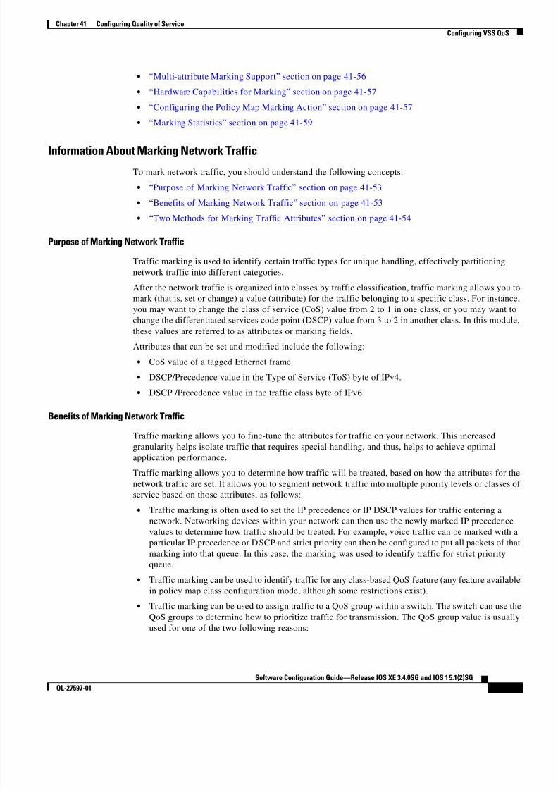
Purpose of Marking Network Traffic
Traffic marking is used to identify certain traffic types for unique handling, effectively partitioning
network traffic into different categories.After the network traffic is organized into classes by traffic classification, traffic marking allows you to
mark (that is, set or change) a value (attribute) for the traffic belonging to a specific class. For instance,
you may want to change the class of service (CoS) value from 2 to 1 in one class, or you may want to
change the differentiated services code point (DSCP) value from 3 to 2 in another class. In this module,
these values are referred to as attributes or marking fields.
Attributes that can be set and modified include the following:
• CoS value of a tagged Ethernet frame
• DSCP/Precedence value in the Type of Service (ToS) byte of IPv4.
• DSCP /Precedence value in the traffic class byte of IPv6
Benefits of Marking Network Traffic
Traffic marking allows you to fine-tune the attributes for traffic on your network. This increased
granularity helps isolate traffic that requires special handling, and thus, helps to achieve optimal
application performance.
Traffic marking allows you to determine how traffic will be treated, based on how the attributes for the
network traffic are set. It allows you to segment network traffic into multiple priority levels or classes of
service based on those attributes, as follows:
• Traffic marking is often used to set the IP precedence or IP DSCP values for traffic entering a
network. Networking devices within your network can then use the newly marked IP precedence
values to determine how traffic should be treated. For example, voice traffic can be marked with a
particular IP precedence or DSCP and strict priority can then be configured to put all packets of that
marking into that queue. In this case, the marking was used to identify traffic for strict priorityqueue.
• Traffic marking can be used to identify traffic for any class-based QoS feature (any feature available
in policy map class configuration mode, although some restrictions exist).
• Traffic marking can be used to assign traffic to a QoS group within a switch. The switch can use the
QoS groups to determine how to prioritize traffic for transmission. The QoS group value is usually
used for one of the two following reasons:

8/11/2019 7 L-Eqos_mrg
http://slidepdf.com/reader/full/7-l-eqosmrg 20/94
41-20
Software Configuration Guide—Release IOS XE 3.4.0SG and IOS 15.1(2)SG
OL-27597-01
Chapter 41 Configuring Quality of Service
Configuring VSS QoS
– To leverage a large range of traffic classes. The QoS group value has 64 different individual
markings, similar to DSCP.
– If changing the Precedence or DSCP value is undesirable.
Two Methods for Marking Traffic Attributes
Note This section describes Unconditional marking, which differs from Policer -based marking.
Unconditional marking is based solely on classification.
Method One: Unconditional Explicit Marking (using the set command)
You specify the traffic attribute you want to change with a set command configured in a policy map. The
following table lists the available set commands and the corresponding attribute. For details on the set
command, refer to the Catalyst 4500 Series Switch Command Reference.
If you are using individual set commands, those set commands are specified in a policy map. The
following is a sample of a policy map configured with one of the set commands listed in Table 41-4.
In this sample configuration, the set cos command has been configured in the policy map (policy1) to
mark the CoS attribute:
enable
configure terminalpolicy map p1
class class1
set cos 3end
For information on configuring a policy map, see the “Creating a Policy Map” section on page 41-51.
The final task is to attach the policy map to the interface. For information on attaching the policy map
to the interface, see the “Attaching a Policy Map to an Interface” section on page 41-51.
Method Two: Unconditional Tablemap-based Marking
You can create a table map that can be used to mark traffic attributes. A table map is a kind of two-way
conversion chart that lists and maps one traffic attribute to another. A table map supports a many-to-one
type of conversion and mapping scheme. The table map establishes a to-from relationship for the traffic
attributes and defines the change to be made to the attribute. That is, an attribute is set to one value thatis taken from another value. The values are based on the specific attribute being changed. For instance,
the Precedence attribute can be a number from 0 to 7, while the DSCP attribute can be a number from 0
to 63.
The following is a sample table map configuration:
table-map table-map1
map from 0 to 1
map from 2 to 3exit
Table 41-2 set Commands and Applicable Packet Types
set Commands Traffic Attribute Packet Typeset cos Layer 2 CoS value of the outgoing traffic Ethernet IPv4, IPv6
set dscp DSCP value in the ToS byte IPv4, IPv6
set precedence precedence value in the packet header IPv4, IPv6
8/11/2019 7 L-Eqos_mrg
http://slidepdf.com/reader/full/7-l-eqosmrg 21/94
41-21
Software Configuration Guide—Release IOS XE 3.4.0SG and IOS 15.1(2)SG
OL-27597-01
Chapter 41 Configuring Quality of Service
Configuring VSS QoS
The following table lists the traffic attributes for which a to-from relationship can be established using
the table map.
The following is an example of a policy map (policy2) configured to use the table map (table-map1)
created earlier:
Policy map policy
class class-default
set cos dscp table table-map
exit
In this example, a mapping relationship was created between the CoS attribute and the DSCP attribute
as defined in the table map.
For information on configuring a policy map to use a table map, “Configuring a Policy Map” section on
page 41-50.
The final task is to attach the policy map to the interface. For information on attaching the policy map
to the interface, see the “Attaching a Policy Map to an Interface” section on page 41-51.
Marking Action Drivers
A marking action can be triggered based on one of the two QoS processing steps.
Classification based: In this case, all the traffic matching a class is marked using either explicit ortablemap based method. This method is referred to as unconditional marking.
Policer result-based: In this case, a class of traffic is marked differently based on the policer result
(conform/exceed/violate) applicable to that packet. This method is referred to as conditional
marking.
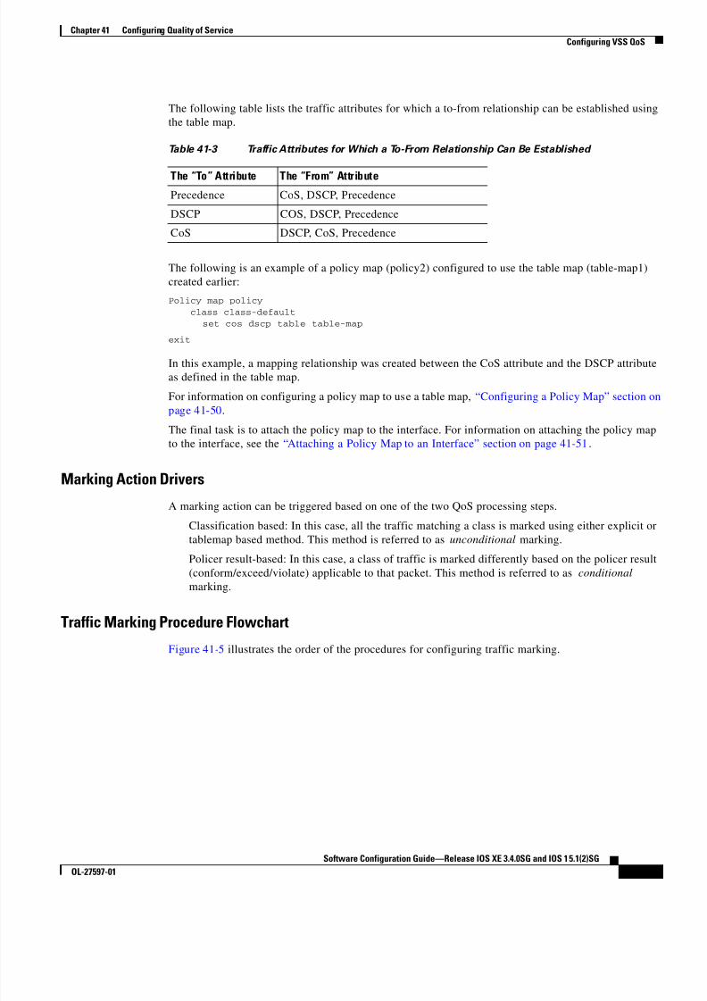
Traffic Marking Procedure Flowchart
Figure 41-5 illustrates the order of the procedures for configuring traffic marking.
Table 41-3 Traffic Attributes for Which a To-From Relationship Can Be Established
The “To” Attribute The “From” Attribute
Precedence CoS, DSCP, Precedence
DSCP COS, DSCP, Precedence
CoS DSCP, CoS, Precedence

8/11/2019 7 L-Eqos_mrg
http://slidepdf.com/reader/full/7-l-eqosmrg 22/94
41-22
Software Configuration Guide—Release IOS XE 3.4.0SG and IOS 15.1(2)SG
OL-27597-01
Chapter 41 Configuring Quality of Service
Configuring VSS QoS
Figure 41-3 Traffic marking Procedure Flowchart
Restrictions for Marking Network Traffic
The following restrictions apply to the following packet marking action:
• Only explicit marking is supported for policer-based marking.
Multi-attribute Marking SupportThe supervisor engine can mark more than one QoS attribute of a packet matching a class of traffic. For
example, DSCP, and CoS can all be set together, using either explicit or tablemap-based marking.
Note When using unconditional explicit marking of multiple fields or policer-based multi-field, multi-region
(conform/exceed/violate) marking the number of tablemaps that can be setup in TOS or COS marking
tables will be less than the maximum supported.
1 2 7 0 7 3
Create a class map
Using atable map?
No Yes
No Yes
Create a policy map
Attach policy map(s)to interface
Create a table map
Start
Finish
Createadditional
policymaps?

8/11/2019 7 L-Eqos_mrg
http://slidepdf.com/reader/full/7-l-eqosmrg 23/94
41-23
Software Configuration Guide—Release IOS XE 3.4.0SG and IOS 15.1(2)SG
OL-27597-01
Chapter 41 Configuring Quality of Service
Configuring VSS QoS
Hardware Capabilities for Marking
Catalyst 4900M, Catalyst 4948E, Supervisor Engine 6-E, and Supervisor Engine 6L-E provide a 128
entry marking action (Supervisor Engine 7-E and Supervisor Engine 7L-E provide a 256 entry marking
action) where each entry specifies the type of marking actions on CoS and DSCP/Precedence fields as
well as policer action to transmit/markdown/drop a packet.
One such table is supported for each direction, input and output. This table is used for both unconditional
marking as well as policer-based marking. It can be used to support 256 unique marking actions or 64
unique policer-based actions or a combinations of the two.
For each of the marking fields (COS and DSCP), the supervisor engine provides 512 entry marking
tables for each direction. These are similar to mapping tables available on supervisor engines that
support the switch QoS model. However, these provide an ability to have multiple unique mapping tables
that are setup by the user.
For example, the TOS marking table provides marking of DSCP/Precedence fields and can be used as
one of the following:
• 64 (32) different tablemaps with each one mapping 8 CoS (16 CoS and CFi) values to DSCP in input
(output) direction
• a combination of above two types of tablemaps
Similar mappings are available on the 512 entry COS marking table.
Configuring the Policy Map Marking Action
This section describes how to establish unconditional marking action for network traffic.
As a prerequisites, create a class map ( ipp5) and a policy map. (Refer to the“Configuring a Policy Map”
section on page 41-50).
Note The marking action command options have been extended (refer to Table 41-4 on page 41-54
andTable 41-5 on page 41-55).
Configuring Tablemap-based Unconditional Marking
To configure table-map based unconditional marking, perform this task:
Command Purpose
Step 1 Switch# configure terminal Enters global configuration mode.
Step 2 Switch(config)# table-map name Configures a tablemap.
Step 3 Switch(config-tablemap)# map from
from_value to to_value
Creates a map from a from_value to a to_value
Step 4 Switch(config-tablemap)# exit Exits table-map configuration mode.
Step 5 Switch(config)# policy-map name Enters policy-map configuration mode.
Step 6 Switch(config-p)# class name Selects the class for QoS actions.
Step 7 Switch(config-p-c)# set cos | dscp |
prec cos | dscp | prec [table name ]Selects the marking action based on an implicit or explicit
table-map.
Step 8 Switch(config-p-c)# end Exits configuration mode.

8/11/2019 7 L-Eqos_mrg
http://slidepdf.com/reader/full/7-l-eqosmrg 24/94
41-24
Software Configuration Guide—Release IOS XE 3.4.0SG and IOS 15.1(2)SG
OL-27597-01
Chapter 41 Configuring Quality of Service
Configuring VSS QoS
The following example shows how to enable marking action using table-map.Switch(config)# table-map dscp2CosSwitch(config-tablemap)# map from 8 to 1
Switch(config-tablemap)# exit
Switch(config)# policy-map p1Switch(config-pmap)# class ipp5
Switch(config-pmap-c)# set cos dscp table dscp2Cos
Switch(config-pmap-c)# endSwitch# show policy-map p1
Policy Map p1 Class ipp5
set cos dscp table dscp2Qos
Switch# show table-map dscp2Cos
Table Map dscp2Cos from 8 to 1
default copy
Configuring Policer Result-based Conditional Marking
To configure policer result-based conditional marking, setup a single rate or dual rate policer. Refer to
the “How to Implement Policing” section on page 41-52.
This example shows how to configure a two rate three-color policer with explicit actions for each policer
region:
Switch# configure terminal
Switch(config-pmap-c)# policer cir percent 20 pir percent 30
Switch(config-pmap-c-policer)# conform-action set-cos-transmit 3 set-dscp-transmit 10Switch(config-pmap-c-policer)# exceed-action set-cos-transmit 4 set-dscp-transmit 20
Switch(config-pmap-c-policer)# violate action drop
Switch# show policy-map p1
Policy Map police
Class ipp5 police cir percent 20 pir percent 30
conform-action set-cos-transmit 3
conform-action set-dscp-transmit af11 exceed-action set-cos-transmit 4
exceed-action set-dscp-transmit af22
violate-action drop
Marking StatisticsThe marking statistics indicate the number of packets that are marked .
For unconditional marking, the classification entry points to an entry in the marking action table that in
turn indicates the fields in the packet that are marked. Therefore, the classification statistics by itself
indicates the unconditional marking statistics.
Step 9 Switch# show policy-map name Verifies the configuration of the policy-map.
Step 10 Switch# show table-map name Verifies the configuration of the table-map.
Command Purpose

8/11/2019 7 L-Eqos_mrg
http://slidepdf.com/reader/full/7-l-eqosmrg 25/94
41-25
Software Configuration Guide—Release IOS XE 3.4.0SG and IOS 15.1(2)SG
OL-27597-01
Chapter 41 Configuring Quality of Service
Configuring VSS QoS
For a conditional marking using policer, provided the policer is a packet rate policer, you cannot
determine the number packets marked because the policer only provides byte statistics for different
policing results.
Shaping, Sharing (Bandwidth), Priority Queuing, Queue-limiting and DBLThe Catalyst 4500 Series Switch supports the Classification-based (class-based) mode for transmit
queue selection. In this mode, the transmit queue selection is based on the Output QoS classification
lookup.
Note Only output (egress) queuing is supported.
The supervisor engine supports 8 transmit queues per port. Once the forwarding decision has been made
to forward a packet out a port, the output QoS classification determines the transmit queue into which
the packet needs to be enqueued.
By default, without any service policies associated with a port, there are two queues (a control packet
queue and a default queue) with no guarantee as to the bandwidth or kind of prioritization. The only
exception is that system generated control packets are enqueued into control packet queue so that control
traffic receives some minimum link bandwidth.
Queues are assigned when an output policy attached to a port with one or more queuing related actions
for one or more classes of traffic. Because there are only eight queues per port, there can be at most eight
classes of traffic (including the reserved class, class-default) with queuing action(s). Classes of traffic
that do not have any queuing action are referred to as non-queuing classes. Non-queuing class traffic
ends up using the queue corresponding to class class-default.
When a queuing policy (a policy with queuing action) is attached, the control packet queue is deleted
and the control packets are enqueued into respective queue per their classification. An egress QoS class
must be configured to match IP Precedence 6 and 7 traffic, and a bandwidth guarantee must be
configured.
Dynamic resizing of queues (queue limit class-map action) is supported through the use of the
queue-limit command. Based on the chassis and line card type, all eight queues on a port are configured
with equal queue size.
Shaping
Shaping enables you to delay out-of-profile packets in queues so that they conform to a specified profile.
Shaping is distinct from policing. Policing drops packets that exceed a configured threshold, whereas
shaping buffers packets so that traffic remains within a given threshold. Shaping offers greater
smoothness in handling traffic than policing. You enable average-rate traffic shaping on a traffic class
with the policy-map class configuration command.
The supervisor engine supports a range of 32kbps to 10 gbps for shaping, with a precision ofapproximately +/- 0.75 per cent.
When a queuing class is configured without any explicit shape configuration, the queue shape is set to
the link rate.

8/11/2019 7 L-Eqos_mrg
http://slidepdf.com/reader/full/7-l-eqosmrg 26/94
41-26
Software Configuration Guide—Release IOS XE 3.4.0SG and IOS 15.1(2)SG
OL-27597-01
Chapter 41 Configuring Quality of Service
Configuring VSS QoS
To configure class-level shaping in a service policy, perform this task:
To delete an existing policy map, use the no policy-map policy-map-name global configuration
command. To delete an existing class, use the no class class-name policy-map configuration command.
To disable the average-rate traffic shaping, use the no shape average policy-map class configuration
command.
This example shows how to configure class-level, average-rate shaping. It limits traffic class class1 to a
data transmission rate of 256 kbps:
Switch# configure terminalSwitch(config)# policy-map policy1
Switch(config-pmap)# class class1
Switch(config-pmap-c)# shape average 256000Switch(config-pmap-c)# exit
Switch(config-pmap)# exit
Switch(config)# interface gigabitethernet1/1
Command Purpose
Step 1 Switch# configure terminal Enters global configuration mode.
Step 2 Switch(config)# policy-map policy-map-name Creates a policy map by entering the policy-map name, and enter
policy-map configuration mode.
By default, no policy maps are defined.
Step 3 Switch(config-pmap)# class class-name Specifies the name of the class whose traffic policy you want to
create or change, and enter policy-map class configuration mode.
By default, no traffic classes are defined.
Step 4 Switch(config-pmap-class)# shape
average {cir-bps [optional_postfix ] |
percent percent}
Enables average-rate traffic shaping.
You can specify the shaping rate in absolute value or as a percentage:
• For cir-bps [optional_postfix ] , specify the shaping rate in bps.
Range is 32000 to 10000000000 bps. Supply an optional postfix
(K, M, G).
• For percent , specify the percentage of link rate to shape the class
of traffic. The range is 1 to 100.
By default, average-rate traffic shaping is disabled.
Step 5 Switch(config-pmap-class)# exit Returns to policy-map configuration mode.
Step 6 Switch(config-pmap)# exit Returns to global configuration mode.
Step 7 Switch(config)# interface interface-id Specifies a physical port and enter interface configuration mode.
Step 8 Switch(config-interface)#
service-policy output policy-map-name Specifies the policy-map name, and apply it a physical interface.
Step 9 Switch(config-interface)# end Returns to privileged EXEC mode.
Step 10 Switch# show policy-map
[ policy-map-name [class
class-map-name ]]
or
Switch# show policy-map interface
interface-id
Verifies your entries.
Step 11 Switch# copy running-config
startup-config (Optional) Saves your entries in the configuration file.

8/11/2019 7 L-Eqos_mrg
http://slidepdf.com/reader/full/7-l-eqosmrg 27/94
41-27
Software Configuration Guide—Release IOS XE 3.4.0SG and IOS 15.1(2)SG
OL-27597-01
Chapter 41 Configuring Quality of Service
Configuring VSS QoS
Switch(config-if)# service-policy output policy1Switch(config-if)# end
Switch#
Switch# show policy-map policy1
Policy Map policy1
Class class1
shape average 256000
This example shows how to configure class-level, average shape percentage to 32% of link bandwidth
for queuing-class traffic:
Switch# configure terminal
Switch(config)# policy-map queuing-policy
Switch(config-pmap)# class queuing-class
Switch(config-pmap-c)# shape average percent 32Switch(config-pmap-c)# exit
Switch(config-pmap)# exit
Switch(config)# interface gigabitethernet1/1Switch(config-if)# service-policy output queuing-policy1
Switch(config-if)# end
Switch #
Switch# show policy-map queuing-policy
Policy Map queuing-policy
Class queuing-class Average Rate Traffic Shaping
cir 32%
Sharing(bandwidth)
The bandwidth assigned to a class of traffic is the minimum bandwidth that is guaranteed to the class
during congestion. Transmit Queue Sharing is the process by which output link bandwidth is shared
among multiple queues of a given port.
The supervisor engine supports a range of 32 kbps to 10 gbps for sharing, with a precision of
approximately +/- 0.75 per cent. The sum of configured bandwidth across all queuing classes should notexceed the link bandwidth.
To configure class-level bandwidth action in a service policy, perform this task:
Command Purpose
Step 1 Switch# configure terminal Enters global configuration mode.
Step 2 Switch(config)# policy-map
policy-map-name
Creates a policy map by entering the policy-map name, and enter
policy-map configuration mode.
By default, no policy maps are defined.
Step 3 Switch(config-pmap)# class class-name Specifies the name of the class whose traffic policy you want to
create or change, and enter policy-map class configuration mode.
By default, no traffic classes are defined.

8/11/2019 7 L-Eqos_mrg
http://slidepdf.com/reader/full/7-l-eqosmrg 28/94
41-28
Software Configuration Guide—Release IOS XE 3.4.0SG and IOS 15.1(2)SG
OL-27597-01
Chapter 41 Configuring Quality of Service
Configuring VSS QoS
To delete an existing policy map, use the no policy-map policy-map-name global configuration
command. To delete an existing class, use the no class class-name policy-map configuration command.
To return to the default bandwidth, use the no bandwidth policy-map class configuration command.
This example shows how to create a class-level policy map called policy11 for three classes called prec1,
prec2, and prec3. In the policy for these classes, 30 percent of the available bandwidth is assigned to the
queue for the first class, 20 percent is assigned to the queue for the second class, and 10 percent is
assigned to the queue for the third class.
Switch # configure terminalSwitch(config)# policy-map policy11
Switch(config-pmap)# class prec1
Switch(config-pmap-c)# bandwidth percent 30Switch(config-pmap-c)# exitSwitch(config-pmap)# class prec2
Switch(config-pmap-c)# bandwidth percent 20
Switch(config-pmap-c)# exitSwitch(config-pmap)# class prec3
Switch(config-pmap-c)# bandwidth percent 10
Switch(config-pmap-c)# exitSwitch(config-pmap)# exit
Switch(config)# interface gigabitethernet1/1
Switch(config-if)# service-policy output policy11
Step 4 Switch(config-pmap-class)# bandwidth
{bandwidth-kbps | percent percent}Specifies the minimum bandwidth provided to a class belonging to
the policy map when there is traffic congestion in the switch. If the
switch is not congested, the class receives more bandwidth than you
specify with the bandwidth command.
By default, no bandwidth is specified.
You can specify the bandwidth in kbps or as a percentage:
o For bandwidth-kbps, specify the bandwidth amount in kbps
assigned to the class. The range is 32 to 10000000.
o For percent , specify the percentage of available bandwidth
assigned to the class. The range is 1 to 100.
Specify all the class bandwidths in either kbps or in percentages, but
not a mix of both.
Step 5 Switch(config-pmap-class)# exit Returns to policy-map configuration mode.
Step 6 Switch(config-pmap)# exit Returns to global configuration mode.
Step 7 Switch(config)# interface interface-id Specifies a physical port and enter interface configuration mode.
Step 8 Switch(config-interface)#
service-policy output policy-map-name Specifies the policy-map name, and apply it a physical interface.
Step 9 Switch(config-interface)# end Returns to privileged EXEC mode.
Step 10 Switch# show policy-map
[ policy-map-name [class
class-map-name ]]
or
Switch# show policy-map interfaceinterface-id
Verifies your entries.
Step 11 Switch# copy running-config
startup-config (Optional) Saves your entries in the configuration file.
Command Purpose

8/11/2019 7 L-Eqos_mrg
http://slidepdf.com/reader/full/7-l-eqosmrg 29/94
41-29
Software Configuration Guide—Release IOS XE 3.4.0SG and IOS 15.1(2)SG
OL-27597-01
Chapter 41 Configuring Quality of Service
Configuring VSS QoS
Switch(config-if)# endSwitch #
Switch# show policy-map policy11 Policy Map policy11
Class prec1
bandwidth percent 30
Class prec2 bandwidth percent 20
Class prec3 bandwidth percent 10
This example shows how to create a class-level policy map called policy11 for three classes called prec1,
prec2, and prec3. In the policy for these classes, 300 mbps of the available bandwidth is assigned to the
queue for the first class, 200 mbps is assigned to the queue for the second class, and 100 mbps is assigned
to the queue for the third class.
Switch # configure terminal
Switch(config)# policy-map policy11
Switch(config-pmap)# class prec1Switch(config-pmap-c)# bandwidth 300000
Switch(config-pmap-c)# exit
Switch(config-pmap)# class prec2Switch(config-pmap-c)# bandwidth 200000Switch(config-pmap-c)# exit
Switch(config-pmap)# class prec3
Switch(config-pmap-c)# bandwidth 100000Switch(config-pmap-c)# exit
Switch(config-pmap)# exit
Switch(config)# interface gigabitethernet1/1
Switch(config-if)# service-policy output policy11Switch(config-if)# end
Switch #
Switch# show policy-map policy11
Policy Map policy11
Class prec1
bandwidth 300000 (kbps) Class prec2
bandwidth 200000 (kbps)
Class prec3 bandwidth 100000 (kbps)
When a queuing class is configured without any explicit share/bandwidth configuration, because the
queue is not guaranteed any minimum bandwidth, the hardware queue is programmed to get a share of
any unallocated bandwidth on the port as shown in the following example.
If there is no bandwidth remaining for the new queue or if the unallocated bandwidth is not sufficient to
meet the minimum configurable rate (32kbps) for all queues which do not have any explicit
share/bandwidth configuration, then the policy association is rejected.
For example, if there are two queues as given below
policy-map queue-policy
class q1 bandwidth percent 10
class q2
bandwidth percent 20
then the bandwidth allocation for the queues is as follows
q1 = 10%
q2 = 20%

8/11/2019 7 L-Eqos_mrg
http://slidepdf.com/reader/full/7-l-eqosmrg 30/94
41-30
Software Configuration Guide—Release IOS XE 3.4.0SG and IOS 15.1(2)SG
OL-27597-01
Chapter 41 Configuring Quality of Service
Configuring VSS QoS
class-default = 70%
Similarly, when another queuing class (say q3) is added without any explicit bandwidth (say, just a shape
command), then the bandwidth allocation is
q1 = 10%
q2 = 20%
q3 = min(35%, q3-shape-rate)class-default = max(35%, (100 - (q1 + q2 + q3 )))
Priority queuing
Only one transmit queue on a port can be configured as strict priority (termed Low Latency Queue, or
LLQ).
LLQ provides strict-priority queuing for a traffic class. It enables delay-sensitive data, such as voice, to
be sent before packets in other queues. The priority queue is serviced first until it is empty or until it is
under its shape rate. Only one traffic stream can be destined for the priority queue per class-level policy.
You enable the priority queue for a traffic class with the priority policy-map class configuration
command at the class mode.
A LLQ can starve other queues unless it is rate limited. The supervisor engine does not support
conditional policing where a 2-parameter policer (rate, burst) becomes effective when the queue is
congested (based on queue length). However, it supports application of an unconditional policer to rate
limit packets enqueued to the strict priority queue.
When a priority queue is configured on one class of a policy map, only bandwidth remaining is accepted
on other classes, guaranteeing a minimum bandwidth for other classes from the remaining bandwidth of
what is left after using the priority queue. When a priority queue is configured with a policer, then either
bandwidth or bandwidth remaining is accepted on other classes.
Note Use bandwidth or bandwidth remaining on all classes. You cannot apply bandwidth on one class and
bandwidth remaining on another class within a policy map.
To enable class-level priority queuing in a service policy, follow these steps:
Command Purpose
Step 1 Switch# configure terminal Enters global configuration mode.
Step 2 Switch(config)# policy-map
policy-map-name
Creates a policy map by entering the policy-map name, and enter
policy-map configuration mode.
By default, no policy maps are defined.
Step 3 Switch(config-pmap)# class class-name Specifies the name of the class whose traffic policy you want to
create or change, and enter policy-map class configuration mode.
By default, no traffic classes are defined.
Step 4 Switch(config-pmap-class)# priority Enables the strict-priority queue, and give priority to a class of
traffic.
By default, strict-priority queueing is disabled.
Step 5 Switch(config-pmap-class)# exit Returns to policy-map configuration mode.
Step 6 Switch(config-pmap)# exit Returns to global configuration mode.
Step 7 Switch(config)# interface interface-id Specifies a physical port and enter interface configuration mode.

8/11/2019 7 L-Eqos_mrg
http://slidepdf.com/reader/full/7-l-eqosmrg 31/94
41-31
Software Configuration Guide—Release IOS XE 3.4.0SG and IOS 15.1(2)SG
OL-27597-01
Chapter 41 Configuring Quality of Service
Configuring VSS QoS
To delete an existing policy map, use the no policy-map policy-map-name global configuration
command. To delete an existing class, use the no class class-name policy-map configuration command.
To disable the priority queue, use the no priority policy-map-class configuration command.
This example shows how to configure a class-level policy called policy1. Class 1 is configured as thepriority queue, which is serviced first until it is empty.
Switch# configure terminal
Switch(config)# policy-map policy1
Switch(config-pmap)# class class1Switch(config-pmap-c)# priority
Switch(config-pmap-c)# exit
Switch(config-pmap)# exitSwitch(config)# interface gigabitethernet1/1
Switch(config-if)# service-policy output policy1
Switch(config-if)# endSwitch #
Switch# show policy-map policy1
Policy Map policy1 Class class1
priority
Queue-limiting
When a class-based queue is instantiated on a physical port, it is set up with a default size. This size
represents the number of queue entries in which packets belonging to that class of traffic can be queued.
The scheduler moves packets from the queue that are ready for transmission, based on the queue shape,
bandwidth, and priority configuration.
The queue-limit provides the maximum number of packets that can be in the queue at any given time.
When the queue is full, an attempt to enqueue any further packets results in tail drop. However, if
dynamic buffer limiting (DBL) is enabled on the queue, packets get a probabilistic drop based on theDBL algorithm, even when the queue is not full.
The queue-limit command can be configured under a class only when queue scheduling, such as
bandwidth, shape, or priority is already configured. The only exception to this requirement is the support
of the stand-alone queue-limit command on the class-default class.
Step 8 Switch(config-interface)#
service-policy output policy-map-name Specifies the policy-map name, and apply it a physical interface.
Step 9 Switch(config-interface)# end Returns to privileged EXEC mode.
Step 10 Switch# show policy-map
[ policy-map-name [classclass-map-name ]]
or
Switch# show policy-map interface
interface-id
Verifies your entries.
Step 11 Switch# copy running-config
startup-config (Optional) Saves your entries in the configuration file.
Command Purpose

8/11/2019 7 L-Eqos_mrg
http://slidepdf.com/reader/full/7-l-eqosmrg 32/94
41-32
Software Configuration Guide—Release IOS XE 3.4.0SG and IOS 15.1(2)SG
OL-27597-01
Chapter 41 Configuring Quality of Service
Configuring VSS QoS
Queue Memory
The number of queue entries that can be allocated has to be a multiple of 8 and can range from 16 to
8184. When a class-based queue is instantiated on a physical port, it is given a default number of entries.
This default queue size is based on the number of slots in the chassis and the number of front-panel ports
in each slot.
Catalyst 4900M, Catalyst 4948E, Supervisor Engine 6-E, and Supervisor Engine 6L-E have 512 K
(524,288) queue entries of which the system sets aside 100 K (102,400) queue entries in a free reserve
pool. Of the remaining 412 K (421,88), the drop port is provided 8184 entries and the CPU ports are
assigned 11704 entries. Supervisor Engine 7-E has 1M (1,048,576) queue entries of which the system
sets aside 100K (102,400) queue entries in a free reserve pool. Of the remaining queue entries, the drop
port is provided 8184 entries, 24576 entries for recirculation ports and the CPU ports are assigned 8656
entries. Supervisor Engine 7L-E has a 512 K queue entries.
The remaining entries are divided equally among the slots in the chassis. In a redundant chassis the two
supervisor slots are treated as one for the purpose of this entries distribution. Within each slot the number
of queue entries are equally divided among the front-panel ports present on the line card in that slot.
When the user configuration for queue entries on an interface exceeds its dedicated quota, the system
attempts to satisfy the configuration from the free reserve pool. The entries from the free reserve poolare allocated to interfaces on a first-come first-served basis.
Service Policy Association
When a QoS service-policy with queuing actions is configured, but no explicit queue-limit command is
attached in the egress direction on a physical interface, each of the class-based queues gets the same
number of queue entries from within the dedicated quota for that physical port. When a queue is
explicitly given a size using the queue-limit command, the switch tries to allocate all the entries from
within the dedicated quota for the interface. If the required number of entries is greater than the
dedicated quota for the interface, the switch tries to allocate the entries from the free reserve.
The queue entries associated with a queue always have to be consecutive. This requirement can result in
fragmentation of the 512K of the queue entries that are shared across the switch. For example, an
interface may not have enough entries for a queue in its dedicated quota and thus have to use the freereserve to set up that queue. In this case, the queue entries from the dedicated quota remain unused
because they cannot be shared with any other port or slot.
When the QoS service-policy associated with an interface is removed, any queue entries taken from the
free reserve are returned to the free reserve pool. The interface queuing configuration reverts to two
queues — class-default and the control-packet queue with default shape, bandwidth, and size. The
control-packet queue is set up with size 16 whereas the default queue is set up with the maximum size
possible based on the dedicated quota for that interface.
Queue Allocation Failure
The switch might not be able to satisfy the explicit queue size required on one or more queues on an
interface because of fragmentation of queue memory or lack of enough free reserve entries. In thisscenario, the switch logs an error message to notify you of the failure. The QoS service-policy is left
configured on the interface. You can fix the error by removing the QoS service-policy and examining the
current usage of the queue entries from the free reserve by other ports on the switch.
Note Do not attach a QoS policy with the maximum queue-limit (8184) to a large number of targets in a VSS
system. This will cause continuous reloads on the standby supervisor engine.

8/11/2019 7 L-Eqos_mrg
http://slidepdf.com/reader/full/7-l-eqosmrg 33/94
41-33
Software Configuration Guide—Release IOS XE 3.4.0SG and IOS 15.1(2)SG
OL-27597-01
Chapter 41 Configuring Quality of Service
Configuring VSS QoS
To configure class-level queue-limit in a service policy, perform this task:
To remove the explicit queue size use the no queue-limit command under the class in a policy-map.
This example shows how to configure a class-based queue with an explicit queue-limit command. It
limits traffic class class1 to a queue of size 4048:
Switch# configure terminal
Switch(config)# policy-map policy1
Switch(config-pmap)# class class1Switch(config-pmap-c)# shape average 256000
Command Purpose
Step 1 Switch# configure terminal Enters global configuration mode.
Step 2 Switch(config)# policy-map policy-map-name Creates a policy map by entering the policy-map name, and enter
policy-map configuration mode.
By default, no policy maps are defined.
Step 3 Switch(config-pmap)# class class-name Specifies the name of the class whose traffic policy you want to
create or change, and enter policy-map class configuration mode.
By default, no traffic classes are defined.
Step 4 Switch(config-pmap-class)# shape
average {cir-bps [optional_postfix ] |
percent percent}
Enables average-rate traffic shaping.
You can specify the shaping rate in absolute value or as a percentage:
• For cir-bps [optional_postfix ] , specify the shaping rate in bps.
Range is 32000 to 10000000000 bps. Supply an optional postfix
(K, M, G).
• For percent , specify the percentage of link rate to shape the class
of traffic. The range is 1 to 100.
By default, average-rate traffic shaping is disabled.
Step 5 Switch(config-pmap-class)# queue-limit
number-of-packets
Provides an explicit queue size in packets. The size must be a
multiple of 8 and ranging from 16 to 8184.
Step 6 Switch(config-pmap-class)# exit Returns to policy-map configuration mode.
Step 7 Switch(config-pmap)# exit Returns to global configuration mode.
Step 8 Switch(config)# interface interface-id Specifies a physical port and enter interface configuration mode.
Step 9 Switch(config-interface)#
service-policy output policy-map-name Specifies the policy-map name, and apply it a physical interface.
Step 10 Switch(config-interface)# end Returns to privileged EXEC mode.
Step 11 Switch# show policy-map
[ policy-map-name [class
class-map-name ]]
or
Switch# show policy-map interface
interface-id
Verifies your entries.
Step 12 Switch# copy running-config
startup-config (Optional) Saves your entries in the configuration file.

8/11/2019 7 L-Eqos_mrg
http://slidepdf.com/reader/full/7-l-eqosmrg 34/94
41-34
Software Configuration Guide—Release IOS XE 3.4.0SG and IOS 15.1(2)SG
OL-27597-01
Chapter 41 Configuring Quality of Service
Configuring VSS QoS
Switch(config-pmap-c)# queue-limit 4048Switch(config-pmap-c)# exit
Switch(config-pmap)# exit
Switch(config)# interface gigabitethernet1/1Switch(config-if)# service-policy output policy1
Switch(config-if)# end
Switch#
Switch# show policy-map policy1
Policy Map policy1 Class class1
shape average 256000
queue-limit 4048Switch#
Active Queue Management (AQM) via Dynamic Buffer Limiting (DBL)
AQM provides buffering control of traffic flows prior to queuing a packet into a transmit queue of a port.
This is of significant interest in a shared memory switch, ensuring that certain flows do not hog the
switch packet memory.
Note The supervisor engine supports active switch buffer management via DBL.
Except for the default class of traffic (class class-default), you can configure DBL action only when at
least one of the other queuing action is configured.
To configure class-level dbl action along with shaping in a service policy, perform this task:
Command Purpose
Step 1 Switch# configure terminal Enters global configuration mode.
Step 2 Switch(config)# policy-map
policy-map-name
Creates a policy map by entering the policy-map name, and enter
policy-map configuration mode.By default, no policy maps are defined.
Step 3 Switch(config-pmap)# class class-name Specifies the name of the class whose traffic policy you want to
create or change, and enter policy-map class configuration mode.
By default, no traffic classes are defined.
Step 4 Switch(config-pmap-class)# shape
average cir-bpsEnables average-rate traffic shaping.
Specify the committed information rate, the bit rate that traffic is
shaped to, in bps. The range is 32000 to 10000000000 bps.
By default, average-rate traffic shaping is disabled.
Step 5 Switch(config-pmap-class)# dbl Enables DBL on the queue associated with this class of traffic
Step 6 Switch(config-pmap-class)# exit Returns to policy-map configuration mode.
Step 7 Switch(config-pmap)# exit Returns to global configuration mode.
Step 8 Switch(config)# interface interface-id Specifies a physical port and enter interface configuration mode.
Step 9 Switch(config-interface)#
service-policy output policy-map-name Specifies the policy-map name, and apply it a physical interface.
Step 10 Switch(config-interface)# end Returns to privileged EXEC mode.

8/11/2019 7 L-Eqos_mrg
http://slidepdf.com/reader/full/7-l-eqosmrg 35/94
41-35
Software Configuration Guide—Release IOS XE 3.4.0SG and IOS 15.1(2)SG
OL-27597-01
Chapter 41 Configuring Quality of Service
Configuring VSS QoS
To delete an existing policy map, use the no policy-map policy-map-name global configuration
command. To delete an existing class, use the no class class-name policy-map configuration command.
To disable DBL on the associated queue, use the no dbl policy-map class configuration command.
The following example shows how to configure class-level, DBL action along with average-rate shaping.
It enables DBL on the queue associated with traffic-class class1.
Switch# configure terminal
Switch(config)# policy-map policy1Switch(config-pmap)# class class1
Switch(config-pmap-c)# shape average 256000
Switch(config-pmap-c)# dbl
Switch(config-pmap-c)# exitSwitch(config-pmap)# exit
Switch(config)# interface gigabitethernet1/1
Switch(config-if)# service-policy output policy1Switch(config-if)# end
Switch#
Switch# show policy-map policy1 Policy Map policy1
Class class1
shape average 256000
dbl
Transmit Queue Statistics
Transmit queue statistics are visible by entering the show policy-map interface command:
Switch# show policy-map interface gigabitEthernet 1/1 GigabitEthernet1/1
Service-policy output: queuing-policy
Class-map: queuing-class (match-all)
1833956 packets
Match: cos 1Queueing
(total drops) 1006239
(bytes output) 56284756 shape (average) cir 320000000, bc 1280000, be 1280000
target shape rate 320000000
Class-map: class-default (match-any)
1 packets
Match: any
(total drops) 0
(bytes output) 2104
Step 11 Switch# show policy-map
[ policy-map-name [class
class-map-name ]]
or
Switch# show policy-map interface
interface-id
Verifies your entries.
Step 12 Switch# copy running-config
startup-config (Optional) Saves your entries in the configuration file.
Command Purpose

8/11/2019 7 L-Eqos_mrg
http://slidepdf.com/reader/full/7-l-eqosmrg 36/94
41-36
Software Configuration Guide—Release IOS XE 3.4.0SG and IOS 15.1(2)SG
OL-27597-01
Chapter 41 Configuring Quality of Service
Configuring VSS QoS
Enabling Per-Port Per-VLAN QoS
The per-port per-VLAN QoS feature enables you to specify different QoS configurations on different
VLANs on a given interface. Typically, you use this feature on trunk or voice VLANs (Cisco IP Phone)
ports, as they belong to multiple VLANs.
To configure per-port per-VLAN QoS, perform this task:
Example 1
Figure 41-6 displays a sample topology for configuring PVQoS. The trunk port gi3/1 is comprised of
multiple VLANs (101 and 102). Within a port, you can create your own service policy per VLAN. This
policy, performed in hardware, might consist of ingress and egress Policing or giving precedence to
voice packet over data.
Figure 41-4 Per-Port Per-VLAN Topology
The following configuration file shows how to perform ingress and egress policing per VLAN using the
policy-map P31_QOS applied to port Gigabit Ethernet 3/1:
ip access-list 101 permit ip host 1.2.2.2 any
Command Purpose
Step 1 Switch(config)# interface {fastethernet | gigabitethernet |
tengigabitethernet} slot/interface | Port-channel number Selects the interface to configure.
Step 2 Switch(config-if)# vlan-range vlan_range Specifies the VLANs involved.
Step 3 Switch(config-if-vlan-range)# service-policy
{input | output} policy-map Specifies the policy-map and direction.
Step 4 Switch(config-if-vlan-range)# exit Exits class-map configuration mode.
Step 5 Switch(config-if)# end Exits configuration interface mode.
Step 6 Switch# show policy-map interfaceinterface_name
Verifies the configuration.
L2 trunk
VLAN
102
VLAN
101
DS P
DS P
Police
Dscp
Port gi3/1L2 trunk
VLAN102
VLAN101
DSCP
DSCP
Police1
Dscp
Port gi3/2
VLAN104
VLAN
103
DSCP
DSCP
CoS
CoS
Service Policy/VLAN
Within a port 1 3 0 6 0 2

8/11/2019 7 L-Eqos_mrg
http://slidepdf.com/reader/full/7-l-eqosmrg 37/94
41-37
Software Configuration Guide—Release IOS XE 3.4.0SG and IOS 15.1(2)SG
OL-27597-01
Chapter 41 Configuring Quality of Service
Configuring VSS QoS
ip access-list 103 permit ip any anyClass-map match-all RT
match ip access-group 101Class-map Match all PD
match ip access-group 103
Policy-map P31_QoS
Class RT
Police 200m 16k conform transmit exceed drop
Class PD
Police 100m 16k conform transmit exceed drop
Interface Gigabit 3/1Switchport
Switchport trunk encapsulation dot1q
Switchport trunk allowed vlan 101-102 Vlan range 101
Service-policy input P31_QoS
Service-policy output P31_QoS
Vlan range 102Service-policy input P32_QoS
Service-policy output P32_QoS
Example 2
Let us assume that interface Gigabit Ethernet 6/1 is a trunk port and belongs to VLANs 20, 300-301, and
400. The following example shows how to apply policy-map p1 for traffic in VLANs 20 and 400 and
policy map p2 to traffic in VLANs 300 through 301:
Switch# configure terminal
Switch(config)# interface gigabitethernet 6/1Switch(config-if)# vlan-range 20,400Switch(config-if-vlan-range)# service-policy input p1
Switch(config-if-vlan-range)# exit
Switch(config-if)# vlan-range 300-301Switch(config-if-vlan-range)# service-policy output p2
Switch(config-if-vlan-range)# end
Switch#
Example 3
The following command shows how to display policy-map statistics on VLAN 20 configured on Gigabit
Ethernet interface 6/1:
Switch# show policy-map interface gigabitEthernet 6/1 vlan 20
GigabitEthernet6/1 vlan 20
Service-policy input: p1
Class-map: c1 (match-all)
0 packets
Match: cos 1Match: access-group 100
police:
cir 100000000 bps, bc 3125000 bytes
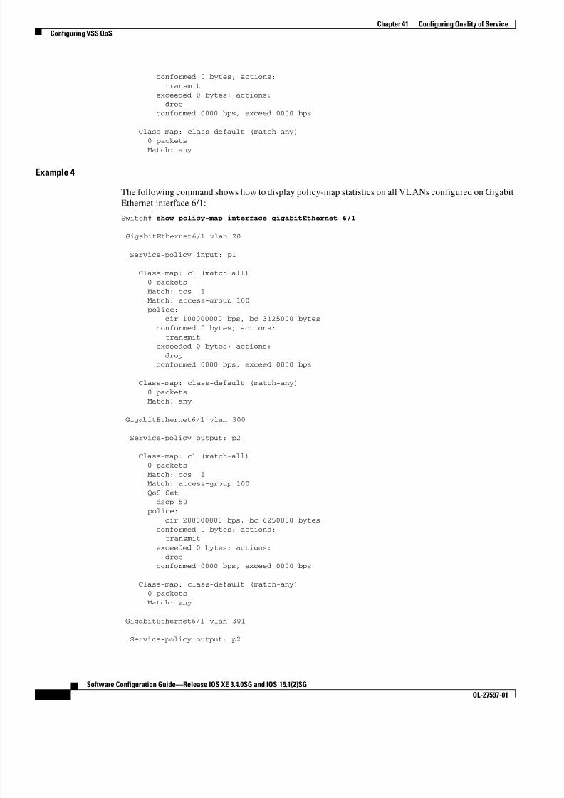
8/11/2019 7 L-Eqos_mrg
http://slidepdf.com/reader/full/7-l-eqosmrg 38/94
41-38
Software Configuration Guide—Release IOS XE 3.4.0SG and IOS 15.1(2)SG
OL-27597-01
Chapter 41 Configuring Quality of Service
Configuring VSS QoS
conformed 0 bytes; actions: transmit
exceeded 0 bytes; actions:
dropconformed 0000 bps, exceed 0000 bps
Class-map: class-default (match-any)
0 packets Match: any
Example 4
The following command shows how to display policy-map statistics on all VLANs configured on Gigabit
Ethernet interface 6/1:
Switch# show policy-map interface gigabitEthernet 6/1
GigabitEthernet6/1 vlan 20
Service-policy input: p1
Class-map: c1 (match-all)
0 packets Match: cos 1
Match: access-group 100
police:
cir 100000000 bps, bc 3125000 bytes
conformed 0 bytes; actions: transmit
exceeded 0 bytes; actions:
dropconformed 0000 bps, exceed 0000 bps
Class-map: class-default (match-any)
0 packets Match: any
GigabitEthernet6/1 vlan 300
Service-policy output: p2
Class-map: c1 (match-all)
0 packets
Match: cos 1Match: access-group 100
QoS Set
dscp 50 police:
cir 200000000 bps, bc 6250000 bytes
conformed 0 bytes; actions: transmit
exceeded 0 bytes; actions:
dropconformed 0000 bps, exceed 0000 bps
Class-map: class-default (match-any) 0 packets
Match: any
GigabitEthernet6/1 vlan 301
Service-policy output: p2

8/11/2019 7 L-Eqos_mrg
http://slidepdf.com/reader/full/7-l-eqosmrg 39/94
41-39
Software Configuration Guide—Release IOS XE 3.4.0SG and IOS 15.1(2)SG
OL-27597-01
Chapter 41 Configuring Quality of Service
Configuring VSS QoS
Class-map: c1 (match-all) 0 packets
Match: cos 1
Match: access-group 100 QoS Set
dscp 50
police:
cir 200000000 bps, bc 6250000 bytes conformed 0 bytes; actions:
transmitexceeded 0 bytes; actions:
drop
conformed 0000 bps, exceed 0000 bps
Policy Associations
The supervisor engine supports per-port, per-VLAN policies. The associated policies are attached to the
interface, VLAN, and a specific VLAN on a given port, respectively.
A policy can be associated with a variety of objects. The following table lists the objects and the actions
allowed.
Qos Action Restrictions
• The same actions cannot be performed multiple times in a given direction on different targets. In
other words, it is not possible to police the packets both on port and VLAN in the input direction.
However, the user can police on the input port and on the output VLAN.
• Queuing actions are only allowed in the egress direction and only on the physical port.
• Percentage-based actions like policer cannot be configured on a VLAN, Port and VLAN (PV) and
EtherChannel.
• Port channel or VLAN configuration can only have a policing or a marking action, not a queueing
action.
Qos Policy priorities
• If a policy on a port and a VLAN are configured with conflicting actions (such as policing or
marking actions on both a port and VLAN), the port policy is picked.
• If policy on a VLAN on a given port must be over-written, the user can configure PV policy.
Table 41-1 Table QoS Policy Associations
Object Action
Physical port Policing, marking, and queuing
VLAN Policing and marking
Port and VLAN (PV) Policing and marking
EtherChannel Policing and marking
EtherChannel member port Queuing

8/11/2019 7 L-Eqos_mrg
http://slidepdf.com/reader/full/7-l-eqosmrg 40/94
41-40
Software Configuration Guide—Release IOS XE 3.4.0SG and IOS 15.1(2)SG
OL-27597-01
Chapter 41 Configuring Quality of Service
Configuring VSS QoS
Qos Policy merging
Applicable policies are applied to a given packet in given direction. For example, if you configure egress
VLAN-based police and marking, followed by selective queuing on the port, then actions from both
policies will be applied for this packet.
The following policy-map configuration restrictions are imposed on an EtherChannel:
• only policing and marking actions are supported at the EtherChannel level
• only queuing actions are supported at the physical member port level
A packet can be marked (dscp or cos fields) by the EtherChannel policy. If the physical member port
policy uses a classification based on dscp or cos fields, it must be based on the marked (modified) value.
To ensure proper operation, the following restriction is placed on the EtherChannel.
The classification criteria for the policy-map on the physical member ports has to based only on one type
of field:
• dscp
• precedence
• cos• any non marking field (no dscp or cos based classification)
Classification criteria for the policy-map on the physical member ports cannot be based on a combination
of fields. This restriction ensures that if the EtherChannel policy is marking down dscp or cos, the
marked (modified) value-based classification can be implemented in hardware.
Note Auto-qos macros with SRND4 generate class-maps with more than one type of match. These class-maps
need to be modified to use only with one matching type when applied on EtherChannel member ports.
Note Classification criteria for the policy-map on the physical member ports cannot be modified to add a new
type of field.
Auto-QoS is not supported on EtherChannel or its member ports. A physical port configured with
Auto-QoS is not allowed to become a member of a physical port.
Software QoS
At the highest level, there are two types of locally sourced traffic (such as control protocol packets,
pings, and telnets) from the switch: high priority traffic (typically the control protocol packets like OSPF
Hellos and STP) and low priority packets (all other packet types).
The QoS treatment for locally-sourced packets differs for the two types.
The supervisor engine provides a way to apply QoS to packets processed in the software path. Thepackets that get this QoS treatment in software can be classified into two types: software switched
packets and software generated packets.
On reception, software switched packets are sent to the CPU that in turn sends them out of another
interface. For such packets, input software QoS provides input marking and output software QoS
provides output marking and queue selection.

8/11/2019 7 L-Eqos_mrg
http://slidepdf.com/reader/full/7-l-eqosmrg 41/94
41-41
Software Configuration Guide—Release IOS XE 3.4.0SG and IOS 15.1(2)SG
OL-27597-01
Chapter 41 Configuring Quality of Service
Configuring VSS QoS
The software generated packets are the ones locally sourced by the switch. The type of output software
QoS processing applied to these packets is the same as the one applied to software switched packets. The
only difference in the two is that the software switched packets take input marking of the packet into
account for output classification purpose.
High Priority Packets
High priority packets are marked as one of the following:
• internally with PAK_PRIORITY
• with IP Precedence of 6 (for IP packets)
• with CoS of 6 (for VLAN Tagged packets)
These packets behave as follows:
• They are not dropped because of any policing, AQM, drop thresholds (or any feature that can drop
a packet) configured as per the egress service policy. However, they might be dropped because of
hardware resource constraints (packet buffers, queue full, etc.).
• They are classified and marked as per the marking configuration of the egress service policy that
could be a port or VLAN (refer to the “Policy Associations” section on page 41-73.
• These high priority packets are enqueued to queue on the egress port based on the following criteria
– If there is no egress queuing policy on the port, the packet is queued to a control packet queue
that is setup separately from the default queue and has 5 percent of the link bandwidth reserved
for it.
– If there is an egress queuing policy on the port, the queue is selected based on the classification
criteria applicable to the packet.
Low Priority Packets
Packets that are not considered high priority (as described previously) are considered unimportant .
These include locally sourced pings, telnet, and other protocol packets. They undergo the same treatment
as any other packet that is transiting the given transmit port including egress classification, marking and
queuing.
Applying Flow-based QoS Policy
Flow based QoS enables microflow policing and marking capability to dynamically learn traffic flows.
It also rate limits each unique flow to an individual rate. Flow based QoS is available with the built-in
NetFlow hardware support.
For more overview information, refer to the “Flow-based QoS” section on page 41-10.
The following steps show how to apply Flow based QoS policy to QoS targets:
Step 1 Create a FNF flow record by specifying the key fields that identify unique flows. You can use any FNF
flow records that are associated with the FNF monitor.
Step 2 Create a class-map to specify the set of match criteria. Include the FNF flow record from Step 1 in the
class-map match criteria using the match flow record command. Then, configure the class-map to
match all the match criteria with class-map match-all class_name.
Step 3 Create a policy-map and define actions associated with class-map from Step 2.

8/11/2019 7 L-Eqos_mrg
http://slidepdf.com/reader/full/7-l-eqosmrg 42/94
41-42
Software Configuration Guide—Release IOS XE 3.4.0SG and IOS 15.1(2)SG
OL-27597-01
Chapter 41 Configuring Quality of Service
Configuring VSS QoS
Step 4 Attach the policy to one or more QoS targets.
Examples
The following examples illustrate how to configure Flow based QoS policy and apply microflow policers
on individual flows.
Example 1
This example assumes there are multiple users (identified by source IP address) on the subnet
192.168.10.*. The configuration below shows how to configure a flow based QoS policy that uses micro
policing to limit the per-user traffic with the source address in the range of 192.168.10.*. The microflow
policer is configured with a CIR of 1Mbps, “conform action” as transmit, and “exceed action” as drop.
Step 1: Define an ACL to match traffic with specified source address.
Switch(config)# ip access-list extended UserGroup1Switch(config-ext-nacl)# permit ip 192.168.10.0 0.0.0.255 any
Switch(config-ext-nacl)# exitSwitch(config)#
Step 2: Define a flow record to create flows with source address as key.
Switch(config)# flow record r1Switch(config-flow-record)# match ipv4 source address
Switch(config-flow-record)# exit
Switch(config)#
Step 3: Configure classmap to match on the UserGroup1 and specify flow record definition for flow
creation.
Switch(config)# class-map match-all c1
Switch(config-cmap)# match access-group name UserGroup1Switch(config-cmap)# match flow record r1
Switch(config-cmap)# exit
Switch(config)#
Step 4: Configure flow based QoS policy-map with microflow policing action for the matching traffic.
Switch(config)# policy-map p1
Switch(config-pmap)# class c1
Switch(config-pmap-c)# police cir 1m
Switch(config-pmap-c-police)# conform-action transmitSwitch(config-pmap-c-police)# exceed-action drop
Switch(config-pmap-c-police)# exit
Switch(config-pmap-c)# exitSwitch(config-pmap)# exit
Step 5: Attach flow QoS policy to the interface.
Switch(config)# interface gigabitEthernet3/1
Switch(config-if)# service-policy input p1Switch(config-if)#
Use the show commands (described in the policy and marking sections of this chapter) to display the
policy-map configuration and interface specific policy-map statistics.

8/11/2019 7 L-Eqos_mrg
http://slidepdf.com/reader/full/7-l-eqosmrg 43/94
41-43
Software Configuration Guide—Release IOS XE 3.4.0SG and IOS 15.1(2)SG
OL-27597-01
Chapter 41 Configuring Quality of Service
Configuring VSS QoS
Example 2.
This example assumes there are multiple users (identified by source IP address) on subnets 192.168.10.*
and 172.20.55.*. The first requirement is to police with a CIR of 500Kbps and a PIR of 650Kbps on any
TCP traffic originating from 192 network to any destination at any given time. The exceed action
keyword marks down the dscp value to 32. The second requirement is to police per-user traffic
originating from 172 network to CIR of 2Mbps and unconditionally mark the traffic with dscp 10.
Step 1: Define an ACL to match traffic with specified source address.
Switch(config)# ip access-list extended UserGroup1
Switch(config-ext-nacl)# permit ip 19 2.168.10.0 0.0.0.255 any
Switch(config-ext-nacl)# exitSwitch(config)# ip access-list extended UserGroup2
Switch(config-ext-nacl)# permit ip 172.20.55.0 0.0.0.255 any
Switch(config-ext-nacl)# exit
Switch(config)#
Step 2: Define a flow record to create flows with source address as key.
Switch(config)# flow record r1
Switch(config-flow-record)# match ipv4 source address
Switch(config-flow-record)# match ipv4 destination addressSwitch(config-flow-record)# match transport tcp source-port
Switch(config-flow-record)# match transport tcp destination-port
Switch(config-flow-record)# exitSwitch(config)# flow record r2
Switch(config-flow-record)# match ipv4 source address
Switch(config-flow-record)# exit
Switch(config)#
Step 3: Configure classmap to match on the UserGroup1 and specify flow record definition for flow
creation.
Switch(config)# class-map match-all c1
Switch(config-cmap)# match access-group name UserGroup1
Switch(config-cmap)# match flow record r1Switch(config-cmap)# exit
Switch(config)# class-map match-all c2
Switch(config-cmap)# match access-group name UserGroup2
Switch(config-cmap)# match flow record r2Switch(config-cmap)# exit
Switch(config)#
Step 4: Configure flow based QoS policy-map with microflow policing action for the matching traffic.
Switch(config)# policy-map p1Switch(config-pmap)# class c1
Switch(config-pmap-c)# police cir 500k pir 650k
Switch(config-pmap-c-police)# conform-action transmitSwitch(config-pmap-c-police)# exceed-action set-dscp-transmit 32
Switch(config-pmap-c-police)# violate-action drop
Switch(config-pmap-c-police)# exit
Switch(config-pmap-c)# exitSwitch(config-pmap)# class c2
Switch(config-pmap-c)# set dscp 10
Switch(config-pmap-c)# police cir 2m Switch(config-pmap-c-police)# conform-action transmit
Switch(config-pmap-c-police)# exceed-action drop
Switch(config-pmap-c-police)# exit
Switch(config-pmap-c)# exitSwitch(config-pmap)# exit
Step 5: Attach flow QoS policy to the interface.

8/11/2019 7 L-Eqos_mrg
http://slidepdf.com/reader/full/7-l-eqosmrg 44/94
41-44
Software Configuration Guide—Release IOS XE 3.4.0SG and IOS 15.1(2)SG
OL-27597-01
Chapter 41 Configuring Quality of Service
Configuring VSS QoS
Switch(config)# interface gigabitEthernet3/1Switch(config-if)# service-policy input p1
Switch(config-if)# exit
Use the show commands described in the QoS section to display the policy-map configuration and
interface specific policy-map statistics.
Example 3
Assume that there are two active flows on FastEthernet interface 6/1:
With the following configuration, each flow is policed to 1000000 bps with an allowed 9000 burst value.Switch(config)# flow record r1
Switch(config-flow-record)# match ipv4 source addressSwitch(config-flow-record)# match ipv4 destination address
Switch(config-flow-record)# match transport tcp source-port
Switch(config-flow-record)# match transport tcp destination-portSwitch(config-flow-record)# match transport udp source-port
Switch(config-flow-record)# match transport udp destination-port
Switch(config-flow-record)# exit
Switch(config)# class-map match-all c1Switch(config-cmap)# match flow record r1
Switch(config-cmap)# exit
Switch(config)# policy-map p1Switch(config-pmap)# class c1
Switch(config-pmap-c)# police 1000000 9000
Switch(config-pmap-c)# exitSwitch(config-pmap)# exitSwitch(config)# interface fastEthernet 6/1
Switch(config-if)# service-policy input p1
Switch(config-if)# end
Configuration Guidelines
The general guidelines for creating, configuring, modifying, deleting a flow based QoS policy and
attaching (and detaching) a flow based QoS policy to a supported target is the same as described in the
QoS section. The following description and restriction applies to Flow based QoS policy:
• A classmap can have multiple match statements but only one FNF flow record can be specified in a
class-map.• A flow record must have at least one key field before it can be used in a classmap. Non-key fields
can be present in the flow record. However, all the non-key fields are ignored by microflow QoS.
Only key-fields are used for flow creation.
• If a FNF flow record is referenced in any class-map, the flow record cannot be modified. Remove
the flow record from all classmaps before modifying it.
• A classmap with a FNF flow record must be configured as match-all; traffic hitting the class-map
must satisfy all match criteria in the class-map.
Table 41-2
SrcIp DStIp IPProt SrcL4Port DstL4Port
192.168.10.10 192.168.20.20 20 6789 81
192.168.10.10 192.168.20.20 20 6789 21

8/11/2019 7 L-Eqos_mrg
http://slidepdf.com/reader/full/7-l-eqosmrg 45/94

8/11/2019 7 L-Eqos_mrg
http://slidepdf.com/reader/full/7-l-eqosmrg 46/94
41-46
Software Configuration Guide—Release IOS XE 3.4.0SG and IOS 15.1(2)SG
OL-27597-01
Chapter 41 Configuring Quality of Service
Configuring VSS QoS
match cos 2
class-map match-all c1
match cos 1
!
policy-map my
class c1
set cos 1
class c2
set cos 2
interface GigabitEthernet2/5
switchport mode trunk
switchport vlan mapping 10 dot1q-tunnel 11
spanning-tree bpdufilter enable
service-policy input my
!
interface GigabitEthernet2/6
switchport mode trunk
Configuring System Queue Limit
Note This feature is available only from Cisco IOS Release 15.0(2)SG1 and later and Cisco IOS Release XE
3.2.1SG.
With the hw-module system max-queue-limit command, the Catalyst 4500 series switch allows you to
change the queue limit for all interfaces globally, instead of applying a policy with queue limit to all the
interfaces.
To set the queue limit globally, perform this task:
Command PurposeStep 1 Switch# configure terminal Enters global configuration mode.
Step 2 Switch(config)# hw-module system
max-queue-limit max-queue-limitSets the queue limit for all interfaces globally.
Valid values are from 1024 to 8184. The value must be a multiple of
8.

8/11/2019 7 L-Eqos_mrg
http://slidepdf.com/reader/full/7-l-eqosmrg 47/94
41-47
Software Configuration Guide—Release IOS XE 3.4.0SG and IOS 15.1(2)SG
OL-27597-01
Chapter 41 Configuring Quality of Service
Configuring QoS on a Standalone Supervisor Engine 6-E/6L-E or Supervisor Engine 7-E/7L-E
This is a global configuration command. You can override it with the per port, per class, queue-limit
command.
For a standalone supervisor engine, you must reboot the engine after applying this command.
For redundant supervisors in SSO mode, you must enter the redundancy reload shelf command enforce
reboot to both the supervisors. For redundancy supervisors in RPR mode, you must execute two
consecutive switchovers to enforce the system queue limit on both the supervisors.
This example shows how to set the queue limit globally to 1024 on a standalone supervisor engine:
Switch> enable
Switch# configure terminal
Switch(config)# hw-module system max-queue-limit 1024
Switch(config)# exitSwitch# reload (for standalone supervisors)
Switch# redundancy reload shelf (for redundancy supervisors in SSO mode)
orSwitch# redundancy force-switchover (followed by another redundancy force-switchover, for
redundancy supervisors in RPR mode)
Configuring QoS on a Standalone Supervisor Engine 6-E/6L-E orSupervisor Engine 7-E/7L-E
Note HQoS is not supported on the Catalyst 4500 Series Switch.
Topics include:
• MQC-based QoS Configuration, page 41-48
• Platform-supported Classification Criteria and QoS Features, page 41-48
• Platform Hardware Capabilities, page 41-49• Prerequisites for Applying a QoS Service Policy, page 41-49
• Restrictions for Applying a QoS Service Policy, page 41-50
• Classification, page 41-50
• Policing, page 41-51
• Marking Network Traffic, page 41-52
• Shaping, Sharing (Bandwidth), Priority Queuing, Queue-limiting and DBL, page 41-59
Step 3 Switch(config)# exit Returns to privileged EXEC mode.
Step 4 Switch# reload
or
Switch# redundancy reload shelf
Switch# redundancy force-switchover
Reloads standalone supervisor engine.
Reloads redundancy supervisor engine in SSO mode.
Reloads redundancy supervisor engine in RPR mode.
This command must be followed by another redundancy
force-switchover.
Command Purpose

8/11/2019 7 L-Eqos_mrg
http://slidepdf.com/reader/full/7-l-eqosmrg 48/94
41-48
Software Configuration Guide—Release IOS XE 3.4.0SG and IOS 15.1(2)SG
OL-27597-01
Chapter 41 Configuring Quality of Service
Configuring QoS on a Standalone Supervisor Engine 6-E/6L-E or Supervisor Engine 7-E/7L-E
• Enabling Per-Port Per-VLAN QoS, page 41-70
• Applying Flow-based QoS Policy, page 41-75
• Configuring CoS Mutation, page 41-79
• Configuring System Queue Limit, page 41-80
MQC-based QoS Configuration
Note Starting with Cisco IOS Release 12.2(40)SG, a Catalyst 4900M, a Catalyst 4948E, or a Catalyst 4500
Series Switch with Supervisor Engine 6-E or Supervisor Engine 6L-E use the MQC model of QoS.
Starting with Cisco IOS Release 15.0(1)XO, a Catalyst 4500 Series Switch using Supervisor Engine
employes the MQC model.
To apply QoS, you use the Modular QoS Command-Line Interface (MQC), which is a CLI structure that
allows you to complete the following tasks:
• Specify the matching criteria used to define a traffic class.
• Create a traffic policy (policy map). The traffic policy defines the QoS policy actions to be taken for
each traffic class.
• Apply the policy actions specified in the policy map to an interface, VLAN, or port and VLAN.
For more information about the MQC, see the “Modular Quality of Service Command-Line Interface”
section of the Cisco IOS Quality of Service Solutions Configuration Guide, Release 12.3.
Note The incoming traffic is considered trusted by default. Only when the trusted boundary feature is enabled
on an interface can the port enter untrusted mode. In this mode, the switch marks the DSCP value of an
IP packet and the CoS value of the VLAN tag on the Ethernet frame as “0”.
Platform-supported Classification Criteria and QoS Features
The following table provides a summary of various classification criteria and actions supported on the
Catalyst 4500 Series Switch. For details, refer to the Catalyst 4500 Series Switch Command Reference.
Supported classification actions Descriptions
match access-group Configures the match criteria for a class map on the basis of the specified ACL.
match any Configures the match criteria for a class map to be successful match criteria for all
packets.
match cos Matches a packet based on a Layer 2 class of service (CoS) marking.
match [ip] dscp Identifies a specific IP differentiated service code point (DSCP) value as a match
criterion. Up to eight DSCP values can be included in one match statement.
match [ip] precedence Identifies IP precedence values as match criteria.
match protocol Configures the match criteria for a class map on the basis of the specified protocol.
match qos-group Identifies a specific QoS group value as a match criterion. Applies only on the egress
direction.
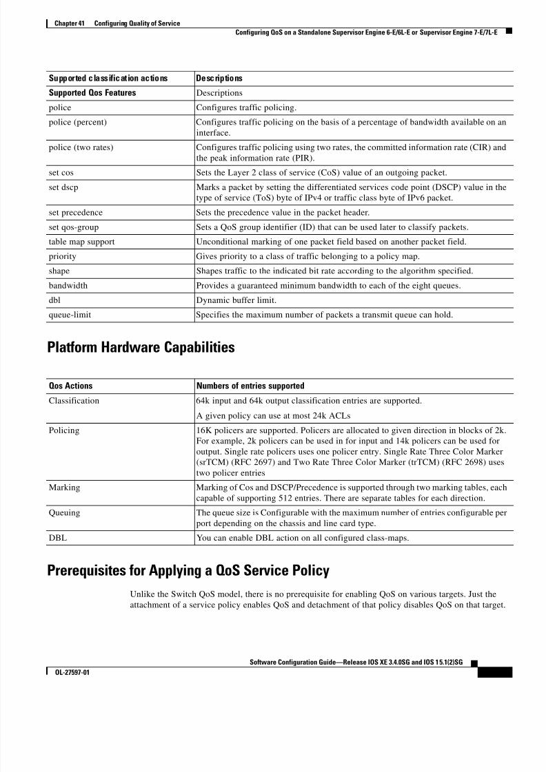
8/11/2019 7 L-Eqos_mrg
http://slidepdf.com/reader/full/7-l-eqosmrg 49/94
41-49
Software Configuration Guide—Release IOS XE 3.4.0SG and IOS 15.1(2)SG
OL-27597-01
Chapter 41 Configuring Quality of Service
Configuring QoS on a Standalone Supervisor Engine 6-E/6L-E or Supervisor Engine 7-E/7L-E
Platform Hardware Capabilities
Prerequisites for Applying a QoS Service Policy
Unlike the Switch QoS model, there is no prerequisite for enabling QoS on various targets. Just the
attachment of a service policy enables QoS and detachment of that policy disables QoS on that target.
Supported Qos Features Descriptions
police Configures traffic policing.
police (percent) Configures traffic policing on the basis of a percentage of bandwidth available on an
interface.police (two rates) Configures traffic policing using two rates, the committed information rate (CIR) and
the peak information rate (PIR).
set cos Sets the Layer 2 class of service (CoS) value of an outgoing packet.
set dscp Marks a packet by setting the differentiated services code point (DSCP) value in the
type of service (ToS) byte of IPv4 or traffic class byte of IPv6 packet.
set precedence Sets the precedence value in the packet header.
set qos-group Sets a QoS group identifier (ID) that can be used later to classify packets.
table map support Unconditional marking of one packet field based on another packet field.
priority Gives priority to a class of traffic belonging to a policy map.
shape Shapes traffic to the indicated bit rate according to the algorithm specified.
bandwidth Provides a guaranteed minimum bandwidth to each of the eight queues.
dbl Dynamic buffer limit.
queue-limit Specifies the maximum number of packets a transmit queue can hold.
Qos Actions Numbers of entries supported
Classification 64k input and 64k output classification entries are supported.
A given policy can use at most 24k ACLs
Policing 16K policers are supported. Policers are allocated to given direction in blocks of 2k.
For example, 2k policers can be used in for input and 14k policers can be used for
output. Single rate policers uses one policer entry. Single Rate Three Color Marker
(srTCM) (RFC 2697) and Two Rate Three Color Marker (trTCM) (RFC 2698) uses
two policer entries
Marking Marking of Cos and DSCP/Precedence is supported through two marking tables, each
capable of supporting 512 entries. There are separate tables for each direction.
Queuing The queue size is Configurable with the maximum number of entries configurable per
port depending on the chassis and line card type.
DBL You can enable DBL action on all configured class-maps.
Supported classification actions Descriptions

8/11/2019 7 L-Eqos_mrg
http://slidepdf.com/reader/full/7-l-eqosmrg 50/94
41-50
Software Configuration Guide—Release IOS XE 3.4.0SG and IOS 15.1(2)SG
OL-27597-01
Chapter 41 Configuring Quality of Service
Configuring QoS on a Standalone Supervisor Engine 6-E/6L-E or Supervisor Engine 7-E/7L-E
Restrictions for Applying a QoS Service Policy
Traffic marking can be configured on an interface, a VLAN, or a port and VLAN. An interface can be a
Layer 2 access port, a Layer 2 switch trunk, a Layer 3 routed port, or an EtherChannel. A policy is
attached to a VLAN using vlan configuration mode.
Attaching QoS service policy to VLANs and EtherChannel is described in the “Policy Associations”section on page 41-73.
Classification
The supervisor engine supports classification of Layer 2, IP, IPv6 packets, and ARP packets marking
performed on input can be matched in the output direction. The previous table lists the full set of
capabilities. By default, the switch also supports classification resources sharing. Similarly, when the
same policy is attached to a port or a VLAN or on per-port per-vlan targets, ACL entries are shared
though QoS actions are unique on each target.
For example:
class-map c1
match ip dscp 50
Policy Map p1
class c1
police rate 1 m burst 200000
If policy-map p1 is applied to interfaces Gig 1/1 and Gig 1/2, 1 CAM entry is used (one ACE that
matches IP packets), but 2 policers are allocated (one per target). So, all IP packets with dscp 50 are
policed to 1 mbps on interface Gig 1/1 and packets on interface Gig 1/2 are policed to 1 mbps.
Note With Cisco IOS Release 12.2(46)SG, you can issue the match protocol arp command. For details, see
the Catalyst 4500 Series Switch Cisco IOS Command Reference.
Classification Statistics
The supervisor engine supports only packet based classification statistics and TCAM resource sharing.
When a policy-map is applied on multiple targets, the command show policy-map interface displays
the aggregate classification statistics, not those specific to an interface.
Note To obtain per interface policy-map stats, you should configure a unique policy-map name on each
interface.
When a policy-map is attached to a port-channel member ports, classification statistics are not displayed.
Configuring a Policy Map
You can attach only one policy map to an interface. Policy maps can contain one or more policy-map
classes, each with different match criteria and actions.
Configure a separate policy-map class in the policy map for each type of traffic that an interface receives.
Put all commands for each type of traffic in the same policy-map class. QoS does not attempt to apply
commands from more than one policy-map class to matched traffic.

8/11/2019 7 L-Eqos_mrg
http://slidepdf.com/reader/full/7-l-eqosmrg 51/94
41-51
Software Configuration Guide—Release IOS XE 3.4.0SG and IOS 15.1(2)SG
OL-27597-01
Chapter 41 Configuring Quality of Service
Configuring QoS on a Standalone Supervisor Engine 6-E/6L-E or Supervisor Engine 7-E/7L-E
Creating a Policy Map
To create a policy map, enter this command:
Attaching a Policy Map to an Interface
To create a policy map, enter this command:
Policing
The supervisor engine supports policers in the following operation modes:
• Single Rate Policer Two Color Marker
This kind of policer is configured with just the committed rate (CIR) and normal burst and it has
only conform and exceed actions.
This is the only form supported in the Supervisor Engine II-Plus to V-10GE based systems.
• Single Rate Three Color Marker (srTCM) (RFC 2697)
• Two Rate Three Color Marker (trTCM) (RFC 2698)
• Color Blind Mode
Policing accuracy of 0.75% of configured policer rate.
The engine supports 16384 (16 x 1024, 16K) single rate, single burst policers. 16K policers are
organized as 8 banks of 2K policers. The policer banks are dynamically assigned (input or outputpolicer bank) by the software depending on the QoS configuration. So, the 16K policers are
dynamically partitioned by software as follows:
– 0 Input Policers and 16K Output Policers
– 2K Input Policers and 14K Output Policers
– 4K Input Policers and 12K Output Policers
– 6K Input Policers and 10K Output Policers
Command Purpose
Switch(config)# [no] policy-map policy_name Creates a policy map with a user-specified name.
Use the no keyword to delete the policy map.
Command Purpose
Switch(config)# interface {vlan vlan_ID |
{fastethernet | gigabitethernet}
slot/interface | Port-channel number }
Selects the interface to configure.
Switch(config-if)# [no] service-policy
input policy_map_name Attaches a policy map to the input direction of the
interface. Use the no keyword to detach a policy
map from an interface.
Switch(config-if)# end Exits configuration mode.
Switch# show policy-map interface {vlan
vlan_ID | {fastethernet | gigabitethernet}
slot/interface}
Verifies the configuration.

8/11/2019 7 L-Eqos_mrg
http://slidepdf.com/reader/full/7-l-eqosmrg 52/94
41-52
Software Configuration Guide—Release IOS XE 3.4.0SG and IOS 15.1(2)SG
OL-27597-01
Chapter 41 Configuring Quality of Service
Configuring QoS on a Standalone Supervisor Engine 6-E/6L-E or Supervisor Engine 7-E/7L-E
– 8K Input Policers and 8K Output Policers
– 10K Input Policers and 6K Output Policers
– 12K Input Policers and 4K Output Policers
– 14K Input Policers and 2K Output Policers
–16K Input Policers and 0 Output Policers
These numbers represent individual policer entries in the hardware that support a single rate and burst
parameter. Based on this, a switch supports the following number of policers:
• 16K Single Rate Policer with Single Burst (Two Color Marker)
• 8K Single Rate Three Color Marker (srTCM)
• 8K Two Rate Three Color Marker (trTCM)
These policers are partitioned between Input and Output in chunks of 2K policer banks. The different
types of policers can all co-exist in the system. However, a given type of policer (srTCM, trTCM etc.) is
configurable as a block of 128 policers.
Note Two policers are reserved for internal use.
How to Implement Policing
For details on how to implement the policing features on a Catalyst 4500 Series Switch, refer to the
Cisco IOS documentation at the following link:
http://www.cisco.com/en/US/docs/ios/12_2/qos/configuration/guide/qcfpolsh.html
Platform Restrictions
Platform restrictions include the following:
• Multi-policer actions can be specified (setting CoS and IP DSCP is supported).
• When unconditional marking and policer based marking exists on the same field(cos or dscp or
precedence), policer-based marking is preferred.
• If policer based service-policy is attached to both a port and a VLAN, port-based policed is preferred
by default. To over-ride a specific VLAN policy on a given port, then you must configure a per-port
per-vlan policy.
• You should not delete a port-channel with a per-port, per-VLAN QoS policy.
Workaround: Before deleting the port-channel, do the following:
1. Remove any per-port per-VLAN QoS policies, if any.
2. Remove the VLAN configuration on the port-channel with the no vlan-range command.
Marking Network Traffic
Marking network traffic allows you to set or modify the attributes of traffic (that is, packets) belonging
to a specific class or category. When used in conjunction with network traffic classification, marking
network traffic is the foundation for enabling many quality of service (QoS) features on your network
This module contains conceptual information and the configuration tasks for marking network traffic.

8/11/2019 7 L-Eqos_mrg
http://slidepdf.com/reader/full/7-l-eqosmrg 53/94
41-53
Software Configuration Guide—Release IOS XE 3.4.0SG and IOS 15.1(2)SG
OL-27597-01
Chapter 41 Configuring Quality of Service
Configuring QoS on a Standalone Supervisor Engine 6-E/6L-E or Supervisor Engine 7-E/7L-E
Contents
• “Information About Marking Network Traffic” section on page 41-53
• “Marking Action Drivers” section on page 41-55
• “Traffic Marking Procedure Flowchart” section on page 41-55
• “Restrictions for Marking Network Traffic” section on page 41-56
• “Multi-attribute Marking Support” section on page 41-56
• “Hardware Capabilities for Marking” section on page 41-57
• “Configuring the Policy Map Marking Action” section on page 41-57
• “Marking Statistics” section on page 41-59
Information About Marking Network Traffic
To mark network traffic, you should understand the following concepts:
• “Purpose of Marking Network Traffic” section on page 41-53
• “Benefits of Marking Network Traffic” section on page 41-53
• “Two Methods for Marking Traffic Attributes” section on page 41-54
Purpose of Marking Network Traffic
Traffic marking is used to identify certain traffic types for unique handling, effectively partitioning
network traffic into different categories.
After the network traffic is organized into classes by traffic classification, traffic marking allows you to
mark (that is, set or change) a value (attribute) for the traffic belonging to a specific class. For instance,
you may want to change the class of service (CoS) value from 2 to 1 in one class, or you may want to
change the differentiated services code point (DSCP) value from 3 to 2 in another class. In this module,
these values are referred to as attributes or marking fields.
Attributes that can be set and modified include the following:
• CoS value of a tagged Ethernet frame
• DSCP/Precedence value in the Type of Service (ToS) byte of IPv4.
• QoS group identifier (ID)
• DSCP /Precedence value in the traffic class byte of IPv6
Benefits of Marking Network Traffic
Traffic marking allows you to fine-tune the attributes for traffic on your network. This increased
granularity helps isolate traffic that requires special handling, and thus, helps to achieve optimal
application performance.
Traffic marking allows you to determine how traffic will be treated, based on how the attributes for the
network traffic are set. It allows you to segment network traffic into multiple priority levels or classes of
service based on those attributes, as follows:
• Traffic marking is often used to set the IP precedence or IP DSCP values for traffic entering a
network. Networking devices within your network can then use the newly marked IP precedence
values to determine how traffic should be treated. For example, voice traffic can be marked with a
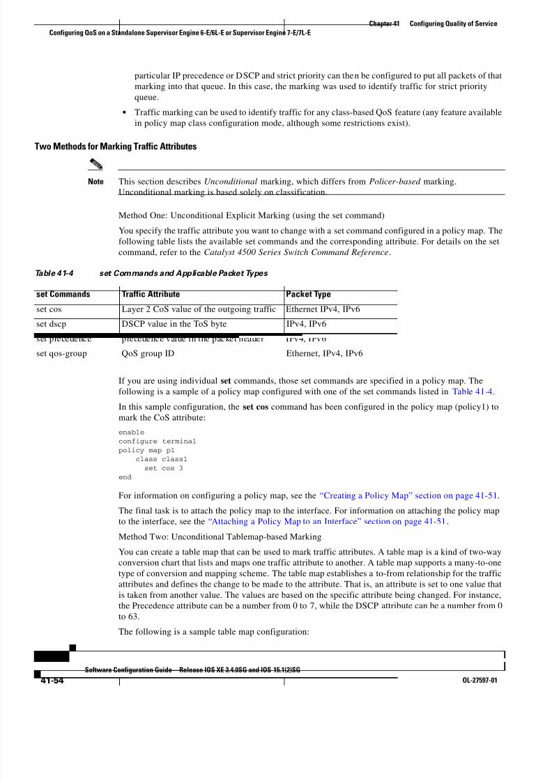
8/11/2019 7 L-Eqos_mrg
http://slidepdf.com/reader/full/7-l-eqosmrg 54/94
41-54
Software Configuration Guide—Release IOS XE 3.4.0SG and IOS 15.1(2)SG
OL-27597-01
Chapter 41 Configuring Quality of Service
Configuring QoS on a Standalone Supervisor Engine 6-E/6L-E or Supervisor Engine 7-E/7L-E
particular IP precedence or DSCP and strict priority can then be configured to put all packets of that
marking into that queue. In this case, the marking was used to identify traffic for strict priority
queue.
• Traffic marking can be used to identify traffic for any class-based QoS feature (any feature available
in policy map class configuration mode, although some restrictions exist).
Two Methods for Marking Traffic Attributes
Note This section describes Unconditional marking, which differs from Policer -based marking.
Unconditional marking is based solely on classification.
Method One: Unconditional Explicit Marking (using the set command)
You specify the traffic attribute you want to change with a set command configured in a policy map. The
following table lists the available set commands and the corresponding attribute. For details on the set
command, refer to the Catalyst 4500 Series Switch Command Reference.
If you are using individual set commands, those set commands are specified in a policy map. The
following is a sample of a policy map configured with one of the set commands listed in Table 41-4.
In this sample configuration, the set cos command has been configured in the policy map (policy1) tomark the CoS attribute:
enable
configure terminal
policy map p1 class class1
set cos 3
end
For information on configuring a policy map, see the “Creating a Policy Map” section on page 41-51.
The final task is to attach the policy map to the interface. For information on attaching the policy map
to the interface, see the “Attaching a Policy Map to an Interface” section on page 41-51.
Method Two: Unconditional Tablemap-based Marking
You can create a table map that can be used to mark traffic attributes. A table map is a kind of two-way
conversion chart that lists and maps one traffic attribute to another. A table map supports a many-to-one
type of conversion and mapping scheme. The table map establishes a to-from relationship for the traffic
attributes and defines the change to be made to the attribute. That is, an attribute is set to one value that
is taken from another value. The values are based on the specific attribute being changed. For instance,
the Precedence attribute can be a number from 0 to 7, while the DSCP attribute can be a number from 0
to 63.
The following is a sample table map configuration:
Table 41-4 set Commands and Applicable Packet Types
set Commands Traffic Attribute Packet Type
set cos Layer 2 CoS value of the outgoing traffic Ethernet IPv4, IPv6
set dscp DSCP value in the ToS byte IPv4, IPv6
set precedence precedence value in the packet header IPv4, IPv6
set qos-group QoS group ID Ethernet, IPv4, IPv6

8/11/2019 7 L-Eqos_mrg
http://slidepdf.com/reader/full/7-l-eqosmrg 55/94
41-55
Software Configuration Guide—Release IOS XE 3.4.0SG and IOS 15.1(2)SG
OL-27597-01
Chapter 41 Configuring Quality of Service
Configuring QoS on a Standalone Supervisor Engine 6-E/6L-E or Supervisor Engine 7-E/7L-E
table-map table-map1 map from 0 to 1
map from 2 to 3
exit
The following table lists the traffic attributes for which a to-from relationship can be established using
the table map.
The following is an example of a policy map (policy2) configured to use the table map (table-map1)
created earlier:
Policy map policy class class-default
set cos dscp table table-map
exit
In this example, a mapping relationship was created between the CoS attribute and the DSCP attribute
as defined in the table map.
For information on configuring a policy map to use a table map, “Configuring a Policy Map” section on
page 41-50.
The final task is to attach the policy map to the interface. For information on attaching the policy map
to the interface, see the “Attaching a Policy Map to an Interface” section on page 41-51.
Marking Action DriversA marking action can be triggered based on one of the two QoS processing steps.
Classification based: In this case, all the traffic matching a class is marked using either explicit or
tablemap based method. This method is referred to as unconditional marking.
Policer result-based: In this case, a class of traffic is marked differently based on the policer result
(conform/exceed/violate) applicable to that packet. This method is referred to as conditional
marking.
Traffic Marking Procedure Flowchart
Figure 41-5 illustrates the order of the procedures for configuring traffic marking.
Table 41-5 Traffic Attributes for Which a To-From Relationship Can Be Established
The “To” Attribute The “From” Attribute
Precedence CoS, QoS group, DSCP, Precedence
DSCP COS, QoS group, DSCP, Precedence
CoS DSCP, QoS group, CoS, Precedence

8/11/2019 7 L-Eqos_mrg
http://slidepdf.com/reader/full/7-l-eqosmrg 56/94
41-56
Software Configuration Guide—Release IOS XE 3.4.0SG and IOS 15.1(2)SG
OL-27597-01
Chapter 41 Configuring Quality of Service
Configuring QoS on a Standalone Supervisor Engine 6-E/6L-E or Supervisor Engine 7-E/7L-E
Figure 41-5 Traffic marking Procedure Flowchart
Restrictions for Marking Network Traffic
The following restrictions apply to packet marking actions:
• QoS-group can be marked only in the input direction and can only support unconditional explicit
marking.
• Only explicit marking is supported for policer-based marking.
Multi-attribute Marking Support
The supervisor engine can mark more than one QoS attribute of a packet matching a class of traffic. For
example, DSCP, CoS, and QoS-group can all be set together, using either explicit or tablemap-based
marking.
1 2 7 0 7 3
Create a class map
Using atable map?
No Yes
No Yes
Create a policy map
Attach policy map(s)to interface
Create a table map
Start
Finish
Createadditional
policymaps?

8/11/2019 7 L-Eqos_mrg
http://slidepdf.com/reader/full/7-l-eqosmrg 57/94
41-57
Software Configuration Guide—Release IOS XE 3.4.0SG and IOS 15.1(2)SG
OL-27597-01
Chapter 41 Configuring Quality of Service
Configuring QoS on a Standalone Supervisor Engine 6-E/6L-E or Supervisor Engine 7-E/7L-E
Note When using unconditional explicit marking of multiple fields or policer-based multi-field, multi-region
(conform/exceed/violate) marking the number of tablemaps that can be setup in TOS or COS marking
tables will be less than the maximum supported.
Hardware Capabilities for Marking
Catalyst 4900M, Catalyst 4948E, Supervisor Engine 6-E, and Supervisor Engine 6L-E provide a 128
entry marking action (Supervisor Engine 7-E and Supervisor Engine 7L-E provide a 256 entry marking
action) where each entry specifies the type of marking actions on CoS and DSCP/Precedence fields as
well as policer action to transmit/markdown/drop a packet.
One such table is supported for each direction, input and output. This table is used for both unconditional
marking as well as policer-based marking. It can be used to support 256 unique marking actions or 64
unique policer-based actions or a combinations of the two.
For each of the marking fields (COS and DSCP), the supervisor engine provides 512 entry marking
tables for each direction. These are similar to mapping tables available on supervisor engines that
support the switch QoS model. However, these provide an ability to have multiple unique mapping tablesthat are setup by the user.
For example, the TOS marking table provides marking of DSCP/Precedence fields and can be used as
one of the following:
• 8 different tablemaps with each mapping the 64 DSCP or qos-group values to another DSCP
• 64 (32) different tablemaps with each one mapping 8 CoS (16 CoS and CFi) values to DSCP in input
(output) direction
• a combination of above two types of tablemaps
Similar mappings are available on the 512 entry COS marking table.
Configuring the Policy Map Marking ActionThis section describes how to establish unconditional marking action for network traffic.
As a prerequisites, create a class map ( ipp5) and a policy map. (Refer to the“Configuring a Policy Map”
section on page 41-50).
Note The marking action command options have been extended (refer to Table 41-4 on page 41-54
andTable 41-5 on page 41-55).
Configuring Tablemap-based Unconditional Marking
To configure table-map based unconditional marking, perform this task:
Command Purpose
Step 1 Switch# configure terminal Enters global configuration mode.
Step 2 Switch(config)# table-map name Configures a tablemap.
Step 3 Switch(config-tablemap)# map fromfrom_value to to_value
Creates a map from a from_value to a to_value
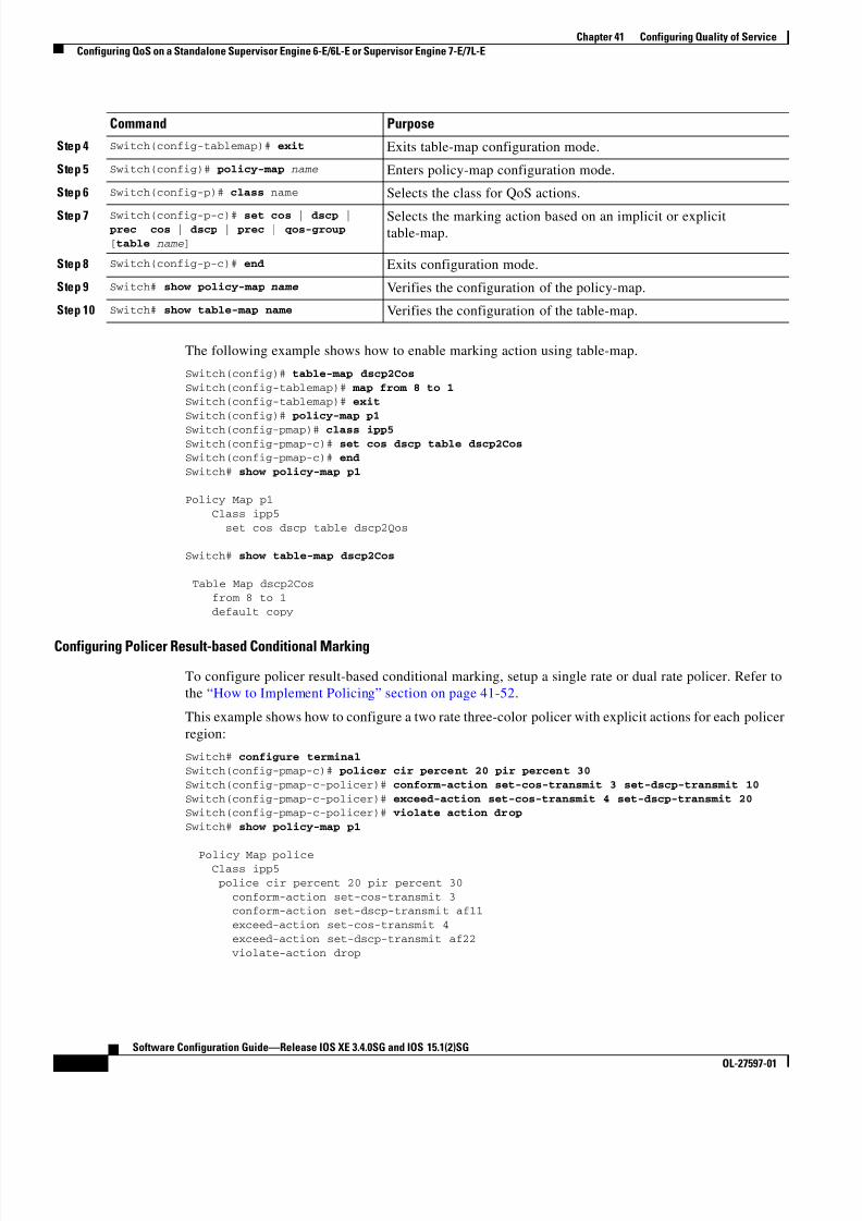
8/11/2019 7 L-Eqos_mrg
http://slidepdf.com/reader/full/7-l-eqosmrg 58/94
41-58
Software Configuration Guide—Release IOS XE 3.4.0SG and IOS 15.1(2)SG
OL-27597-01
Chapter 41 Configuring Quality of Service
Configuring QoS on a Standalone Supervisor Engine 6-E/6L-E or Supervisor Engine 7-E/7L-E
The following example shows how to enable marking action using table-map.
Switch(config)# table-map dscp2Cos
Switch(config-tablemap)# map from 8 to 1Switch(config-tablemap)# exit
Switch(config)# policy-map p1
Switch(config-pmap)# class ipp5Switch(config-pmap-c)# set cos dscp table dscp2CosSwitch(config-pmap-c)# end
Switch# show policy-map p1
Policy Map p1
Class ipp5
set cos dscp table dscp2Qos
Switch# show table-map dscp2Cos
Table Map dscp2Cos from 8 to 1
default copy
Configuring Policer Result-based Conditional Marking
To configure policer result-based conditional marking, setup a single rate or dual rate policer. Refer to
the “How to Implement Policing” section on page 41-52.
This example shows how to configure a two rate three-color policer with explicit actions for each policer
region:
Switch# configure terminalSwitch(config-pmap-c)# policer cir percent 20 pir percent 30
Switch(config-pmap-c-policer)# conform-action set-cos-transmit 3 set-dscp-transmit 10
Switch(config-pmap-c-policer)# exceed-action set-cos-transmit 4 set-dscp-transmit 20Switch(config-pmap-c-policer)# violate action drop
Switch# show policy-map p1
Policy Map police Class ipp5
police cir percent 20 pir percent 30
conform-action set-cos-transmit 3 conform-action set-dscp-transmit af11
exceed-action set-cos-transmit 4
exceed-action set-dscp-transmit af22
violate-action drop
Step 4 Switch(config-tablemap)# exit Exits table-map configuration mode.
Step 5 Switch(config)# policy-map name Enters policy-map configuration mode.
Step 6 Switch(config-p)# class name Selects the class for QoS actions.
Step 7 Switch(config-p-c)# set cos | dscp | prec cos | dscp | prec | qos-group
[table name ]
Selects the marking action based on an implicit or explicittable-map.
Step 8 Switch(config-p-c)# end Exits configuration mode.
Step 9 Switch# show policy-map name Verifies the configuration of the policy-map.
Step 10 Switch# show table-map name Verifies the configuration of the table-map.
Command Purpose
8/11/2019 7 L-Eqos_mrg
http://slidepdf.com/reader/full/7-l-eqosmrg 59/94
41-59
Software Configuration Guide—Release IOS XE 3.4.0SG and IOS 15.1(2)SG
OL-27597-01
Chapter 41 Configuring Quality of Service
Configuring QoS on a Standalone Supervisor Engine 6-E/6L-E or Supervisor Engine 7-E/7L-E
Marking Statistics
The marking statistics indicate the number of packets that are marked .
For unconditional marking, the classification entry points to an entry in the marking action table that in
turn indicates the fields in the packet that are marked. Therefore, the classification statistics by itself
indicates the unconditional marking statistics.For a conditional marking using policer, provided the policer is a packet rate policer, you cannot
determine the number packets marked because the policer only provides byte statistics for different
policing results.
Shaping, Sharing (Bandwidth), Priority Queuing, Queue-limiting and DBL
The Catalyst 4500 Series Switch supports the Classification-based (class-based) mode for transmit
queue selection. In this mode, the transmit queue selection is based on the Output QoS classification
lookup.
Note Only output (egress) queuing is supported.
The supervisor engine supports 8 transmit queues per port. Once the forwarding decision has been made
to forward a packet out a port, the output QoS classification determines the transmit queue into which
the packet needs to be enqueued.
By default, without any service policies associated with a port, there are two queues (a control packet
queue and a default queue) with no guarantee as to the bandwidth or kind of prioritization. The only
exception is that system generated control packets are enqueued into control packet queue so that control
traffic receives some minimum link bandwidth.
Queues are assigned when an output policy attached to a port with one or more queuing related actions
for one or more classes of traffic. Because there are only eight queues per port, there can be at most eight
classes of traffic (including the reserved class, class-default) with queuing action(s). Classes of trafficthat do not have any queuing action are referred to as non-queuing classes. Non-queuing class traffic
ends up using the queue corresponding to class class-default.
When a queuing policy (a policy with queuing action) is attached, the control packet queue is deleted
and the control packets are enqueued into respective queue per their classification. An egress QoS class
must be configured to match IP Precedence 6 and 7 traffic, and a bandwidth guarantee must be
configured.
Dynamic resizing of queues (queue limit class-map action) is supported through the use of the
queue-limit command. Based on the chassis and line card type, all eight queues on a port are configured
with equal queue size.
ShapingShaping enables you to delay out-of-profile packets in queues so that they conform to a specified profile.
Shaping is distinct from policing. Policing drops packets that exceed a configured threshold, whereas
shaping buffers packets so that traffic remains within a given threshold. Shaping offers greater
smoothness in handling traffic than policing. You enable average-rate traffic shaping on a traffic class
with the policy-map class configuration command.
The supervisor engine supports a range of 32kbps to 10 gbps for shaping, with a precision of
approximately +/- 0.75 per cent.

8/11/2019 7 L-Eqos_mrg
http://slidepdf.com/reader/full/7-l-eqosmrg 60/94
41-60
Software Configuration Guide—Release IOS XE 3.4.0SG and IOS 15.1(2)SG
OL-27597-01
Chapter 41 Configuring Quality of Service
Configuring QoS on a Standalone Supervisor Engine 6-E/6L-E or Supervisor Engine 7-E/7L-E
When a queuing class is configured without any explicit shape configuration, the queue shape is set to
the link rate.
To configure class-level shaping in a service policy, perform this task:
To delete an existing policy map, use the no policy-map policy-map-name global configuration
command. To delete an existing class, use the no class class-name policy-map configuration command.
To disable the average-rate traffic shaping, use the no shape average policy-map class configuration
command.
This example shows how to configure class-level, average-rate shaping. It limits traffic class class1 to a
data transmission rate of 256 kbps:
Switch# configure terminal
Switch(config)# policy-map policy1Switch(config-pmap)# class class1
Switch(config-pmap-c)# shape average 256000
Command Purpose
Step 1 Switch# configure terminal Enters global configuration mode.
Step 2 Switch(config)# policy-map
policy-map-name
Creates a policy map by entering the policy-map name, and enter
policy-map configuration mode.
By default, no policy maps are defined.
Step 3 Switch(config-pmap)# class class-name Specifies the name of the class whose traffic policy you want to
create or change, and enter policy-map class configuration mode.
By default, no traffic classes are defined.
Step 4 Switch(config-pmap-class)# shape
average {cir-bps [optional_postfix ] |
percent percent}
Enables average-rate traffic shaping.
You can specify the shaping rate in absolute value or as a percentage:
• For cir-bps [optional_postfix ] , specify the shaping rate in bps.Range is 32000 to 10000000000 bps. Supply an optional postfix
(K, M, G).
• For percent , specify the percentage of link rate to shape the class
of traffic. The range is 1 to 100.
By default, average-rate traffic shaping is disabled.
Step 5 Switch(config-pmap-class)# exit Returns to policy-map configuration mode.
Step 6 Switch(config-pmap)# exit Returns to global configuration mode.
Step 7 Switch(config)# interface interface-id Specifies a physical port and enter interface configuration mode.
Step 8 Switch(config-interface)#
service-policy output policy-map-name Specifies the policy-map name, and apply it a physical interface.
Step 9 Switch(config-interface)# end Returns to privileged EXEC mode.
Step 10 Switch# show policy-map
[ policy-map-name [class
class-map-name ]]
or
Switch# show policy-map interfaceinterface-id
Verifies your entries.
Step 11 Switch# copy running-config
startup-config (Optional) Saves your entries in the configuration file.

8/11/2019 7 L-Eqos_mrg
http://slidepdf.com/reader/full/7-l-eqosmrg 61/94
41-61
Software Configuration Guide—Release IOS XE 3.4.0SG and IOS 15.1(2)SG
OL-27597-01
Chapter 41 Configuring Quality of Service
Configuring QoS on a Standalone Supervisor Engine 6-E/6L-E or Supervisor Engine 7-E/7L-E
Switch(config-pmap-c)# exitSwitch(config-pmap)# exit
Switch(config)# interface gigabitethernet1/1
Switch(config-if)# service-policy output policy1Switch(config-if)# end
Switch#
Switch# show policy-map policy1 Policy Map policy1
Class class1 shape average 256000
This example shows how to configure class-level, average shape percentage to 32% of link bandwidth
for queuing-class traffic:
Switch# configure terminalSwitch(config)# policy-map queuing-policy
Switch(config-pmap)# class queuing-class
Switch(config-pmap-c)# shape average percent 32Switch(config-pmap-c)# exit
Switch(config-pmap)# exit
Switch(config)# interface gigabitethernet1/1
Switch(config-if)# service-policy output queuing-policy1Switch(config-if)# end
Switch #
Switch# show policy-map queuing-policy
Policy Map queuing-policy
Class queuing-class
Average Rate Traffic Shaping cir 32%
Sharing(bandwidth)
The bandwidth assigned to a class of traffic is the minimum bandwidth that is guaranteed to the class
during congestion. Transmit Queue Sharing is the process by which output link bandwidth is shared
among multiple queues of a given port.
The supervisor engine supports a range of 32 kbps to 10 gbps for sharing, with a precision of
approximately +/- 0.75 per cent. The sum of configured bandwidth across all queuing classes should not
exceed the link bandwidth.
To configure class-level bandwidth action in a service policy, perform this task:
Command Purpose
Step 1 Switch# configure terminal Enters global configuration mode.
Step 2 Switch(config)# policy-map
policy-map-name
Creates a policy map by entering the policy-map name, and enter
policy-map configuration mode.
By default, no policy maps are defined.
Step 3 Switch(config-pmap)# class class-name Specifies the name of the class whose traffic policy you want to
create or change, and enter policy-map class configuration mode.
By default, no traffic classes are defined.

8/11/2019 7 L-Eqos_mrg
http://slidepdf.com/reader/full/7-l-eqosmrg 62/94
41-62
Software Configuration Guide—Release IOS XE 3.4.0SG and IOS 15.1(2)SG
OL-27597-01
Chapter 41 Configuring Quality of Service
Configuring QoS on a Standalone Supervisor Engine 6-E/6L-E or Supervisor Engine 7-E/7L-E
To delete an existing policy map, use the no policy-map policy-map-name global configuration
command. To delete an existing class, use the no class class-name policy-map configuration command.
To return to the default bandwidth, use the no bandwidth policy-map class configuration command.
This example shows how to create a class-level policy map called policy11 for three classes called prec1,
prec2, and prec3. In the policy for these classes, 30 percent of the available bandwidth is assigned to the
queue for the first class, 20 percent is assigned to the queue for the second class, and 10 percent is
assigned to the queue for the third class.
Switch # configure terminalSwitch(config)# policy-map policy11
Switch(config-pmap)# class prec1
Switch(config-pmap-c)# bandwidth percent 30Switch(config-pmap-c)# exitSwitch(config-pmap)# class prec2
Switch(config-pmap-c)# bandwidth percent 20
Switch(config-pmap-c)# exitSwitch(config-pmap)# class prec3
Switch(config-pmap-c)# bandwidth percent 10
Switch(config-pmap-c)# exitSwitch(config-pmap)# exit
Switch(config)# interface gigabitethernet1/1
Switch(config-if)# service-policy output policy11
Step 4 Switch(config-pmap-class)# bandwidth
{bandwidth-kbps | percent percent}Specifies the minimum bandwidth provided to a class belonging to
the policy map when there is traffic congestion in the switch. If the
switch is not congested, the class receives more bandwidth than you
specify with the bandwidth command.
By default, no bandwidth is specified.
You can specify the bandwidth in kbps or as a percentage:
o For bandwidth-kbps, specify the bandwidth amount in kbps
assigned to the class. The range is 32 to 10000000.
o For percent , specify the percentage of available bandwidth
assigned to the class. The range is 1 to 100.
Specify all the class bandwidths in either kbps or in percentages, but
not a mix of both.
Step 5 Switch(config-pmap-class)# exit Returns to policy-map configuration mode.
Step 6 Switch(config-pmap)# exit Returns to global configuration mode.
Step 7 Switch(config)# interface interface-id Specifies a physical port and enter interface configuration mode.
Step 8 Switch(config-interface)#
service-policy output policy-map-name Specifies the policy-map name, and apply it a physical interface.
Step 9 Switch(config-interface)# end Returns to privileged EXEC mode.
Step 10 Switch# show policy-map
[ policy-map-name [class
class-map-name ]]
or
Switch# show policy-map interfaceinterface-id
Verifies your entries.
Step 11 Switch# copy running-config
startup-config (Optional) Saves your entries in the configuration file.
Command Purpose

8/11/2019 7 L-Eqos_mrg
http://slidepdf.com/reader/full/7-l-eqosmrg 63/94
41-63
Software Configuration Guide—Release IOS XE 3.4.0SG and IOS 15.1(2)SG
OL-27597-01
Chapter 41 Configuring Quality of Service
Configuring QoS on a Standalone Supervisor Engine 6-E/6L-E or Supervisor Engine 7-E/7L-E
Switch(config-if)# endSwitch #
Switch# show policy-map policy11 Policy Map policy11
Class prec1
bandwidth percent 30
Class prec2 bandwidth percent 20
Class prec3 bandwidth percent 10
This example shows how to create a class-level policy map called policy11 for three classes called prec1,
prec2, and prec3. In the policy for these classes, 300 mbps of the available bandwidth is assigned to the
queue for the first class, 200 mbps is assigned to the queue for the second class, and 100 mbps is assigned
to the queue for the third class.
Switch # configure terminal
Switch(config)# policy-map policy11
Switch(config-pmap)# class prec1Switch(config-pmap-c)# bandwidth 300000
Switch(config-pmap-c)# exit
Switch(config-pmap)# class prec2Switch(config-pmap-c)# bandwidth 200000Switch(config-pmap-c)# exit
Switch(config-pmap)# class prec3
Switch(config-pmap-c)# bandwidth 100000Switch(config-pmap-c)# exit
Switch(config-pmap)# exit
Switch(config)# interface gigabitethernet1/1
Switch(config-if)# service-policy output policy11Switch(config-if)# end
Switch #
Switch# show policy-map policy11
Policy Map policy11
Class prec1
bandwidth 300000 (kbps) Class prec2
bandwidth 200000 (kbps)
Class prec3 bandwidth 100000 (kbps)
When a queuing class is configured without any explicit share/bandwidth configuration, because the
queue is not guaranteed any minimum bandwidth, the hardware queue is programmed to get a share of
any unallocated bandwidth on the port as shown in the following example.
If there is no bandwidth remaining for the new queue or if the unallocated bandwidth is not sufficient to
meet the minimum configurable rate (32kbps) for all queues which do not have any explicit
share/bandwidth configuration, then the policy association is rejected.
For example, if there are two queues as given below
policy-map queue-policy
class q1 bandwidth percent 10
class q2
bandwidth percent 20
then the bandwidth allocation for the queues is as follows
q1 = 10%
q2 = 20%

8/11/2019 7 L-Eqos_mrg
http://slidepdf.com/reader/full/7-l-eqosmrg 64/94
41-64
Software Configuration Guide—Release IOS XE 3.4.0SG and IOS 15.1(2)SG
OL-27597-01
Chapter 41 Configuring Quality of Service
Configuring QoS on a Standalone Supervisor Engine 6-E/6L-E or Supervisor Engine 7-E/7L-E
class-default = 70%
Similarly, when another queuing class (say q3) is added without any explicit bandwidth (say, just a shape
command), then the bandwidth allocation is
q1 = 10%
q2 = 20%
q3 = min(35%, q3-shape-rate)class-default = max(35%, (100 - (q1 + q2 + q3 )))
Priority queuing
Only one transmit queue on a port can be configured as strict priority (termed Low Latency Queue, or
LLQ).
LLQ provides strict-priority queuing for a traffic class. It enables delay-sensitive data, such as voice, to
be sent before packets in other queues. The priority queue is serviced first until it is empty or until it is
under its shape rate. Only one traffic stream can be destined for the priority queue per class-level policy.
You enable the priority queue for a traffic class with the priority policy-map class configuration
command at the class mode.
A LLQ can starve other queues unless it is rate limited. The supervisor engine does not support
conditional policing where a 2-parameter policer (rate, burst) becomes effective when the queue is
congested (based on queue length). However, it supports application of an unconditional policer to rate
limit packets enqueued to the strict priority queue.
When a priority queue is configured on one class of a policy map, only bandwidth remaining is accepted
on other classes, guaranteeing a minimum bandwidth for other classes from the remaining bandwidth of
what is left after using the priority queue. When a priority queue is configured with a policer, then either
bandwidth or bandwidth remaining is accepted on other classes.
Note Use bandwidth or bandwidth remaining on all classes. You cannot apply bandwidth on one class and
bandwidth remaining on another class within a policy map.
To enable class-level priority queuing in a service policy, follow these steps:
Command Purpose
Step 1 Switch# configure terminal Enters global configuration mode.
Step 2 Switch(config)# policy-map
policy-map-name
Creates a policy map by entering the policy-map name, and enter
policy-map configuration mode.
By default, no policy maps are defined.
Step 3 Switch(config-pmap)# class class-name Specifies the name of the class whose traffic policy you want to
create or change, and enter policy-map class configuration mode.
By default, no traffic classes are defined.
Step 4 Switch(config-pmap-class)# priority Enables the strict-priority queue, and give priority to a class of
traffic.
By default, strict-priority queueing is disabled.
Step 5 Switch(config-pmap-class)# exit Returns to policy-map configuration mode.
Step 6 Switch(config-pmap)# exit Returns to global configuration mode.
Step 7 Switch(config)# interface interface-id Specifies a physical port and enter interface configuration mode.

8/11/2019 7 L-Eqos_mrg
http://slidepdf.com/reader/full/7-l-eqosmrg 65/94
41-65
Software Configuration Guide—Release IOS XE 3.4.0SG and IOS 15.1(2)SG
OL-27597-01
Chapter 41 Configuring Quality of Service
Configuring QoS on a Standalone Supervisor Engine 6-E/6L-E or Supervisor Engine 7-E/7L-E
To delete an existing policy map, use the no policy-map policy-map-name global configuration
command. To delete an existing class, use the no class class-name policy-map configuration command.
To disable the priority queue, use the no priority policy-map-class configuration command.
This example shows how to configure a class-level policy called policy1. Class 1 is configured as thepriority queue, which is serviced first until it is empty.
Switch# configure terminal
Switch(config)# policy-map policy1
Switch(config-pmap)# class class1Switch(config-pmap-c)# priority
Switch(config-pmap-c)# exit
Switch(config-pmap)# exitSwitch(config)# interface gigabitethernet1/1
Switch(config-if)# service-policy output policy1
Switch(config-if)# endSwitch #
Switch# show policy-map policy1
Policy Map policy1 Class class1
priority
Queue-limiting
When a class-based queue is instantiated on a physical port, it is set up with a default size. This size
represents the number of queue entries in which packets belonging to that class of traffic can be queued.
The scheduler moves packets from the queue that are ready for transmission, based on the queue shape,
bandwidth, and priority configuration.
The queue-limit provides the maximum number of packets that can be in the queue at any given time.
When the queue is full, an attempt to enqueue any further packets results in tail drop. However, if
dynamic buffer limiting (DBL) is enabled on the queue, packets get a probabilistic drop based on theDBL algorithm, even when the queue is not full.
The queue-limit command can be configured under a class only when queue scheduling, such as
bandwidth, shape, or priority is already configured. The only exception to this requirement is the support
of the stand-alone queue-limit command on the class-default class.
Step 8 Switch(config-interface)#
service-policy output policy-map-name Specifies the policy-map name, and apply it a physical interface.
Step 9 Switch(config-interface)# end Returns to privileged EXEC mode.
Step 10 Switch# show policy-map
[ policy-map-name [classclass-map-name ]]
or
Switch# show policy-map interface
interface-id
Verifies your entries.
Step 11 Switch# copy running-config
startup-config (Optional) Saves your entries in the configuration file.
Command Purpose

8/11/2019 7 L-Eqos_mrg
http://slidepdf.com/reader/full/7-l-eqosmrg 66/94
41-66
Software Configuration Guide—Release IOS XE 3.4.0SG and IOS 15.1(2)SG
OL-27597-01
Chapter 41 Configuring Quality of Service
Configuring QoS on a Standalone Supervisor Engine 6-E/6L-E or Supervisor Engine 7-E/7L-E
Queue Memory
The number of queue entries that can be allocated has to be a multiple of 8 and can range from 16 to
8184. When a class-based queue is instantiated on a physical port, it is given a default number of entries.
This default queue size is based on the number of slots in the chassis and the number of front-panel ports
in each slot.
Catalyst 4900M, Catalyst 4948E, Supervisor Engine 6-E, and Supervisor Engine 6L-E have 512 K
(524,288) queue entries of which the system sets aside 100 K (102,400) queue entries in a free reserve
pool. Of the remaining 412 K (421,88), the drop port is provided 8184 entries and the CPU ports are
assigned 11704 entries. Supervisor Engine 7-E has 1M (1,048,576) queue entries of which the system
sets aside 100K (102,400) queue entries in a free reserve pool. Of the remaining queue entries, the drop
port is provided 8184 entries, 24576 entries for recirculation ports and the CPU ports are assigned 8656
entries. Supervisor Engine 7L-E has a 512 K queue entries.
The remaining entries are divided equally among the slots in the chassis. In a redundant chassis the two
supervisor slots are treated as one for the purpose of this entries distribution. Within each slot the number
of queue entries are equally divided among the front-panel ports present on the line card in that slot.
When the user configuration for queue entries on an interface exceeds its dedicated quota, the system
attempts to satisfy the configuration from the free reserve pool. The entries from the free reserve poolare allocated to interfaces on a first-come first-served basis.
Service Policy Association
When a QoS service-policy with queuing actions is configured, but no explicit queue-limit command is
attached in the egress direction on a physical interface, each of the class-based queues gets the same
number of queue entries from within the dedicated quota for that physical port. When a queue is
explicitly given a size using the queue-limit command, the switch tries to allocate all the entries from
within the dedicated quota for the interface. If the required number of entries is greater than the
dedicated quota for the interface, the switch tries to allocate the entries from the free reserve.
The queue entries associated with a queue always have to be consecutive. This requirement can result in
fragmentation of the 512K of the queue entries that are shared across the switch. For example, an
interface may not have enough entries for a queue in its dedicated quota and thus have to use the freereserve to set up that queue. In this case, the queue entries from the dedicated quota remain unused
because they cannot be shared with any other port or slot.
When the QoS service-policy associated with an interface is removed, any queue entries taken from the
free reserve are returned to the free reserve pool. The interface queuing configuration reverts to two
queues — class-default and the control-packet queue with default shape, bandwidth, and size. The
control-packet queue is set up with size 16 whereas the default queue is set up with the maximum size
possible based on the dedicated quota for that interface.
Queue Allocation Failure
The switch might not be able to satisfy the explicit queue size required on one or more queues on an
interface because of fragmentation of queue memory or lack of enough free reserve entries. In thisscenario, the switch logs an error message to notify you of the failure. The QoS service-policy is left
configured on the interface. You can fix the error by removing the QoS service-policy and examining the
current usage of the queue entries from the free reserve by other ports on the switch.
To configure class-level queue-limit in a service policy, perform this task:

8/11/2019 7 L-Eqos_mrg
http://slidepdf.com/reader/full/7-l-eqosmrg 67/94
41-67
Software Configuration Guide—Release IOS XE 3.4.0SG and IOS 15.1(2)SG
OL-27597-01
Chapter 41 Configuring Quality of Service
Configuring QoS on a Standalone Supervisor Engine 6-E/6L-E or Supervisor Engine 7-E/7L-E
To remove the explicit queue size use the no queue-limit command under the class in a policy-map.
This example shows how to configure a class-based queue with an explicit queue-limit command. It
limits traffic class class1 to a queue of size 4048:
Switch# configure terminal
Switch(config)# policy-map policy1Switch(config-pmap)# class class1
Switch(config-pmap-c)# shape average 256000
Switch(config-pmap-c)# queue-limit 4048
Switch(config-pmap-c)# exitSwitch(config-pmap)# exit
Switch(config)# interface gigabitethernet1/1
Switch(config-if)# service-policy output policy1
Command Purpose
Step 1 Switch# configure terminal Enters global configuration mode.
Step 2 Switch(config)# policy-map
policy-map-name
Creates a policy map by entering the policy-map name, and enter
policy-map configuration mode.
By default, no policy maps are defined.
Step 3 Switch(config-pmap)# class class-name Specifies the name of the class whose traffic policy you want to
create or change, and enter policy-map class configuration mode.
By default, no traffic classes are defined.
Step 4 Switch(config-pmap-class)# shape
average {cir-bps [optional_postfix ] | percent percent}
Enables average-rate traffic shaping.
You can specify the shaping rate in absolute value or as a percentage:
• For cir-bps [optional_postfix ] , specify the shaping rate in bps.
Range is 32000 to 10000000000 bps. Supply an optional postfix
(K, M, G).
• For percent , specify the percentage of link rate to shape the class
of traffic. The range is 1 to 100.
By default, average-rate traffic shaping is disabled.
Step 5 Switch(config-pmap-class)# queue-limitnumber-of-packets
Provides an explicit queue size in packets. The size must be a
multiple of 8 and ranging from 16 to 8184.
Step 6 Switch(config-pmap-class)# exit Returns to policy-map configuration mode.
Step 7 Switch(config-pmap)# exit Returns to global configuration mode.
Step 8 Switch(config)# interface interface-id Specifies a physical port and enter interface configuration mode.
Step 9 Switch(config-interface)#
service-policy output policy-map-name Specifies the policy-map name, and apply it a physical interface.
Step 10 Switch(config-interface)# end Returns to privileged EXEC mode.
Step 11 Switch# show policy-map
[ policy-map-name [class
class-map-name ]]
or
Switch# show policy-map interface
interface-id
Verifies your entries.
Step 12 Switch# copy running-config
startup-config (Optional) Saves your entries in the configuration file.

8/11/2019 7 L-Eqos_mrg
http://slidepdf.com/reader/full/7-l-eqosmrg 68/94
41-68
Software Configuration Guide—Release IOS XE 3.4.0SG and IOS 15.1(2)SG
OL-27597-01
Chapter 41 Configuring Quality of Service
Configuring QoS on a Standalone Supervisor Engine 6-E/6L-E or Supervisor Engine 7-E/7L-E
Switch(config-if)# endSwitch#
Switch# show policy-map policy1 Policy Map policy1
Class class1
shape average 256000
queue-limit 4048Switch#
Active Queue Management (AQM) via Dynamic Buffer Limiting (DBL)
AQM provides buffering control of traffic flows prior to queuing a packet into a transmit queue of a port.
This is of significant interest in a shared memory switch, ensuring that certain flows do not hog the
switch packet memory.
Note The supervisor engine supports active switch buffer management via DBL.
Except for the default class of traffic (class class-default), you can configure DBL action only when at
least one of the other queuing action is configured.
To configure class-level dbl action along with shaping in a service policy, perform this task:
Command Purpose
Step 1 Switch# configure terminal Enters global configuration mode.
Step 2 Switch(config)# policy-map
policy-map-name
Creates a policy map by entering the policy-map name, and enter
policy-map configuration mode.
By default, no policy maps are defined.
Step 3 Switch(config-pmap)# class class-name Specifies the name of the class whose traffic policy you want to
create or change, and enter policy-map class configuration mode.
By default, no traffic classes are defined.
Step 4 Switch(config-pmap-class)# shape
average cir-bpsEnables average-rate traffic shaping.
Specify the committed information rate, the bit rate that traffic is
shaped to, in bps. The range is 32000 to 10000000000 bps.
By default, average-rate traffic shaping is disabled.
Step 5 Switch(config-pmap-class)# dbl Enables DBL on the queue associated with this class of traffic
Step 6 Switch(config-pmap-class)# exit Returns to policy-map configuration mode.
Step 7 Switch(config-pmap)# exit Returns to global configuration mode.
Step 8 Switch(config)# interface interface-id Specifies a physical port and enter interface configuration mode.
Step 9 Switch(config-interface)#service-policy output policy-map-name
Specifies the policy-map name, and apply it a physical interface.
Step 10 Switch(config-interface)# end Returns to privileged EXEC mode.

8/11/2019 7 L-Eqos_mrg
http://slidepdf.com/reader/full/7-l-eqosmrg 69/94
41-69
Software Configuration Guide—Release IOS XE 3.4.0SG and IOS 15.1(2)SG
OL-27597-01
Chapter 41 Configuring Quality of Service
Configuring QoS on a Standalone Supervisor Engine 6-E/6L-E or Supervisor Engine 7-E/7L-E
To delete an existing policy map, use the no policy-map policy-map-name global configuration
command. To delete an existing class, use the no class class-name policy-map configuration command.
To disable DBL on the associated queue, use the no dbl policy-map class configuration command.
The following example shows how to configure class-level, DBL action along with average-rate shaping.
It enables DBL on the queue associated with traffic-class class1.
Switch# configure terminal
Switch(config)# policy-map policy1Switch(config-pmap)# class class1
Switch(config-pmap-c)# shape average 256000
Switch(config-pmap-c)# dbl
Switch(config-pmap-c)# exitSwitch(config-pmap)# exit
Switch(config)# interface gigabitethernet1/1
Switch(config-if)# service-policy output policy1Switch(config-if)# end
Switch#
Switch# show policy-map policy1 Policy Map policy1
Class class1
shape average 256000
dbl
Transmit Queue Statistics
Transmit queue statistics are visible by entering the show policy-map interface command:
Switch# show policy-map interface gigabitEthernet 1/1 GigabitEthernet1/1
Service-policy output: queuing-policy
Class-map: queuing-class (match-all)
1833956 packets
Match: cos 1Queueing
(total drops) 1006239
(bytes output) 56284756 shape (average) cir 320000000, bc 1280000, be 1280000
target shape rate 320000000
Class-map: class-default (match-any)
1 packets
Match: any
(total drops) 0
(bytes output) 2104
Step 11 Switch# show policy-map
[ policy-map-name [class
class-map-name ]]
or
Switch# show policy-map interface
interface-id
Verifies your entries.
Step 12 Switch# copy running-config
startup-config (Optional) Saves your entries in the configuration file.
Command Purpose

8/11/2019 7 L-Eqos_mrg
http://slidepdf.com/reader/full/7-l-eqosmrg 70/94
41-70
Software Configuration Guide—Release IOS XE 3.4.0SG and IOS 15.1(2)SG
OL-27597-01
Chapter 41 Configuring Quality of Service
Configuring QoS on a Standalone Supervisor Engine 6-E/6L-E or Supervisor Engine 7-E/7L-E
Enabling Per-Port Per-VLAN QoS
The per-port per-VLAN QoS feature enables you to specify different QoS configurations on different
VLANs on a given interface. Typically, you use this feature on trunk or voice VLANs (Cisco IP Phone)
ports, as they belong to multiple VLANs.
To configure per-port per-VLAN QoS, perform this task:
Example 1
Figure 41-6 displays a sample topology for configuring PVQoS. The trunk port gi3/1 is comprised of
multiple VLANs (101 and 102). Within a port, you can create your own service policy per VLAN. This
policy, performed in hardware, might consist of ingress and egress Policing or giving precedence to
voice packet over data.
Figure 41-6 Per-Port Per-VLAN Topology
The following configuration file shows how to perform ingress and egress policing per VLAN using the
policy-map P31_QOS applied to port Gigabit Ethernet 3/1:
ip access-list 101 permit ip host 1.2.2.2 any
Command Purpose
Step 1 Switch(config)# interface {fastethernet | gigabitethernet |
tengigabitethernet} slot/interface | Port-channel number Selects the interface to configure.
Step 2 Switch(config-if)# vlan-range vlan_range Specifies the VLANs involved.
Step 3 Switch(config-if-vlan-range)# service-policy
{input | output} policy-map Specifies the policy-map and direction.
Step 4 Switch(config-if-vlan-range)# exit Exits class-map configuration mode.
Step 5 Switch(config-if)# end Exits configuration interface mode.
Step 6 Switch# show policy-map interfaceinterface_name
Verifies the configuration.
L2 trunk
VLAN
102
VLAN
101
DS P
DS P
Police
Dscp
Port gi3/1L2 trunk
VLAN102
VLAN101
DSCP
DSCP
Police1
Dscp
Port gi3/2
VLAN104
VLAN
103
DSCP
DSCP
CoS
CoS
Service Policy/VLAN
Within a port 1 3 0 6 0 2

8/11/2019 7 L-Eqos_mrg
http://slidepdf.com/reader/full/7-l-eqosmrg 71/94
41-71
Software Configuration Guide—Release IOS XE 3.4.0SG and IOS 15.1(2)SG
OL-27597-01
Chapter 41 Configuring Quality of Service
Configuring QoS on a Standalone Supervisor Engine 6-E/6L-E or Supervisor Engine 7-E/7L-E
ip access-list 103 permit ip any anyClass-map match-all RT
match ip access-group 101Class-map Match all PD
match ip access-group 103
Policy-map P31_QoS
Class RT
Police 200m 16k conform transmit exceed drop
Class PD
Police 100m 16k conform transmit exceed drop
Interface Gigabit 3/1Switchport
Switchport trunk encapsulation dot1q
Switchport trunk allowed vlan 101-102 Vlan range 101
Service-policy input P31_QoS
Service-policy output P31_QoS
Vlan range 102Service-policy input P32_QoS
Service-policy output P32_QoS
Example 2
Let us assume that interface Gigabit Ethernet 6/1 is a trunk port and belongs to VLANs 20, 300-301, and
400. The following example shows how to apply policy-map p1 for traffic in VLANs 20 and 400 and
policy map p2 to traffic in VLANs 300 through 301:
Switch# configure terminal
Switch(config)# interface gigabitethernet 6/1Switch(config-if)# vlan-range 20,400Switch(config-if-vlan-range)# service-policy input p1
Switch(config-if-vlan-range)# exit
Switch(config-if)# vlan-range 300-301Switch(config-if-vlan-range)# service-policy output p2
Switch(config-if-vlan-range)# end
Switch#
Example 3
The following command shows how to display policy-map statistics on VLAN 20 configured on Gigabit
Ethernet interface 6/1:
Switch# show policy-map interface gigabitEthernet 6/1 vlan 20
GigabitEthernet6/1 vlan 20
Service-policy input: p1
Class-map: c1 (match-all)
0 packets
Match: cos 1Match: access-group 100
police:
cir 100000000 bps, bc 3125000 bytes

8/11/2019 7 L-Eqos_mrg
http://slidepdf.com/reader/full/7-l-eqosmrg 72/94
41-72
Software Configuration Guide—Release IOS XE 3.4.0SG and IOS 15.1(2)SG
OL-27597-01
Chapter 41 Configuring Quality of Service
Configuring QoS on a Standalone Supervisor Engine 6-E/6L-E or Supervisor Engine 7-E/7L-E
conformed 0 bytes; actions: transmit
exceeded 0 bytes; actions:
dropconformed 0000 bps, exceed 0000 bps
Class-map: class-default (match-any)
0 packets Match: any
Example 4
The following command shows how to display policy-map statistics on all VLANs configured on Gigabit
Ethernet interface 6/1:
Switch# show policy-map interface gigabitEthernet 6/1
GigabitEthernet6/1 vlan 20
Service-policy input: p1
Class-map: c1 (match-all)
0 packets Match: cos 1
Match: access-group 100
police:
cir 100000000 bps, bc 3125000 bytes
conformed 0 bytes; actions: transmit
exceeded 0 bytes; actions:
dropconformed 0000 bps, exceed 0000 bps
Class-map: class-default (match-any)
0 packets Match: any
GigabitEthernet6/1 vlan 300
Service-policy output: p2
Class-map: c1 (match-all)
0 packets
Match: cos 1Match: access-group 100
QoS Set
dscp 50 police:
cir 200000000 bps, bc 6250000 bytes
conformed 0 bytes; actions: transmit
exceeded 0 bytes; actions:
dropconformed 0000 bps, exceed 0000 bps
Class-map: class-default (match-any) 0 packets
Match: any
GigabitEthernet6/1 vlan 301
Service-policy output: p2

8/11/2019 7 L-Eqos_mrg
http://slidepdf.com/reader/full/7-l-eqosmrg 73/94
41-73
Software Configuration Guide—Release IOS XE 3.4.0SG and IOS 15.1(2)SG
OL-27597-01
Chapter 41 Configuring Quality of Service
Configuring QoS on a Standalone Supervisor Engine 6-E/6L-E or Supervisor Engine 7-E/7L-E
Class-map: c1 (match-all) 0 packets
Match: cos 1
Match: access-group 100 QoS Set
dscp 50
police:
cir 200000000 bps, bc 6250000 bytes conformed 0 bytes; actions:
transmitexceeded 0 bytes; actions:
drop
conformed 0000 bps, exceed 0000 bps
Policy Associations
The supervisor engine supports per-port, per-VLAN policies. The associated policies are attached to the
interface, VLAN, and a specific VLAN on a given port, respectively.
A policy can be associated with a variety of objects. The following table lists the objects and the actions
allowed.
Qos Action Restrictions
• The same actions cannot be performed multiple times in a given direction on different targets. In
other words, it is not possible to police the packets both on port and VLAN in the input direction.
However, the user can police on the input port and on the output VLAN.
• Queuing actions are only allowed in the egress direction and only on the physical port.
• Percentage-based actions like policer cannot be configured on a VLAN, Port and VLAN (PV) and
EtherChannel.
• Port channel or VLAN configuration can only have a policing or a marking action, not a queueing
action.
Qos Policy priorities
• If a policy on a port and a VLAN are configured with conflicting actions (such as policing or
marking actions on both a port and VLAN), the port policy is picked.
• If policy on a VLAN on a given port must be over-written, the user can configure PV policy.
Table 41-3 Table QoS Policy Associations
Object Action
Physical port Policing, marking, and queuing
VLAN Policing and marking
Port and VLAN (PV) Policing and marking
EtherChannel Policing and marking
EtherChannel member port Queuing
8/11/2019 7 L-Eqos_mrg
http://slidepdf.com/reader/full/7-l-eqosmrg 74/94
41-74
Software Configuration Guide—Release IOS XE 3.4.0SG and IOS 15.1(2)SG
OL-27597-01
Chapter 41 Configuring Quality of Service
Configuring QoS on a Standalone Supervisor Engine 6-E/6L-E or Supervisor Engine 7-E/7L-E
Qos Policy merging
Applicable policies are applied to a given packet in given direction. For example, if you configure egress
VLAN-based police and marking, followed by selective queuing on the port, then actions from both
policies will be applied for this packet.
The following policy-map configuration restrictions are imposed on an EtherChannel:
• only policing and marking actions are supported at the EtherChannel level
• only queuing actions are supported at the physical member port level
A packet can be marked (dscp or cos fields) by the EtherChannel policy. If the physical member port
policy uses a classification based on dscp or cos fields, it must be based on the marked (modified) value.
To ensure proper operation, the following restriction is placed on the EtherChannel.
The classification criteria for the policy-map on the physical member ports has to based only on one type
of field:
• dscp
• precedence
• cos• any non marking field (no dscp or cos based classification)
Classification criteria for the policy-map on the physical member ports cannot be based on a combination
of fields. This restriction ensures that if the EtherChannel policy is marking down dscp or cos, the
marked (modified) value-based classification can be implemented in hardware.
Note Classification criteria for the policy-map on the physical member ports cannot be modified to add a new
type of field.
Auto-QoS is not supported on EtherChannel or its member ports. A physical port configured with
Auto-QoS is not allowed to become a member of a physical port.
Software QoS
At the highest level, there are two types of locally sourced traffic (such as control protocol packets,
pings, and telnets) from the switch: high priority traffic (typically the control protocol packets like OSPF
Hellos and STP) and low priority packets (all other packet types).
The QoS treatment for locally-sourced packets differs for the two types.
The supervisor engine provides a way to apply QoS to packets processed in the software path. The
packets that get this QoS treatment in software can be classified into two types: software switched
packets and software generated packets.
On reception, software switched packets are sent to the CPU that in turn sends them out of another
interface. For such packets, input software QoS provides input marking and output software QoSprovides output marking and queue selection.
The software generated packets are the ones locally sourced by the switch. The type of output software
QoS processing applied to these packets is the same as the one applied to software switched packets. The
only difference in the two is that the software switched packets take input marking of the packet into
account for output classification purpose.

8/11/2019 7 L-Eqos_mrg
http://slidepdf.com/reader/full/7-l-eqosmrg 75/94
41-75
Software Configuration Guide—Release IOS XE 3.4.0SG and IOS 15.1(2)SG
OL-27597-01
Chapter 41 Configuring Quality of Service
Configuring QoS on a Standalone Supervisor Engine 6-E/6L-E or Supervisor Engine 7-E/7L-E
High Priority Packets
High priority packets are marked as one of the following:
• internally with PAK_PRIORITY
• with IP Precedence of 6 (for IP packets)
• with CoS of 6 (for VLAN Tagged packets)
These packets behave as follows:
• They are not dropped because of any policing, AQM, drop thresholds (or any feature that can drop
a packet) configured as per the egress service policy. However, they might be dropped because of
hardware resource constraints (packet buffers, queue full, etc.).
• They are classified and marked as per the marking configuration of the egress service policy that
could be a port or VLAN (refer to the “Policy Associations” section on page 41-73.
• These high priority packets are enqueued to queue on the egress port based on the following criteria
– If there is no egress queuing policy on the port, the packet is queued to a control packet queue
that is setup separately from the default queue and has 5 percent of the link bandwidth reserved
for it.– If there is an egress queuing policy on the port, the queue is selected based on the classification
criteria applicable to the packet.
Low Priority Packets
Packets that are not considered high priority (as described previously) are considered unimportant .
These include locally sourced pings, telnet, and other protocol packets. They undergo the same treatment
as any other packet that is transiting the given transmit port including egress classification, marking and
queuing.
Applying Flow-based QoS PolicyFlow based QoS enables microflow policing and marking capability to dynamically learn traffic flows.
It also rate limits each unique flow to an individual rate. Flow based QoS is available with the built-in
NetFlow hardware support.
For more overview information, refer to the “Flow-based QoS” section on page 41-10.
The following steps show how to apply Flow based QoS policy to QoS targets:
Step 1 Create a FNF flow record by specifying the key fields that identify unique flows. You can use any FNF
flow records that are associated with the FNF monitor.
Step 2 Create a class-map to specify the set of match criteria. Include the FNF flow record from Step 1 in the
class-map match criteria using the match flow record command. Then, configure the class-map tomatch all the match criteria with class-map match-all class_name.
Step 3 Create a policy-map and define actions associated with class-map from Step 2.
Step 4 Attach the policy to one or more QoS targets.

8/11/2019 7 L-Eqos_mrg
http://slidepdf.com/reader/full/7-l-eqosmrg 76/94
41-76
Software Configuration Guide—Release IOS XE 3.4.0SG and IOS 15.1(2)SG
OL-27597-01
Chapter 41 Configuring Quality of Service
Configuring QoS on a Standalone Supervisor Engine 6-E/6L-E or Supervisor Engine 7-E/7L-E
Examples
The following examples illustrate how to configure Flow based QoS policy and apply microflow policers
on individual flows.
Example 1
This example assumes there are multiple users (identified by source IP address) on the subnet
192.168.10.*. The configuration below shows how to configure a flow based QoS policy that uses micro
policing to limit the per-user traffic with the source address in the range of 192.168.10.*. The microflow
policer is configured with a CIR of 1Mbps, “conform action” as transmit, and “exceed action” as drop.
Step 1: Define an ACL to match traffic with specified source address.
Switch(config)# ip access-list extended UserGroup1
Switch(config-ext-nacl)# permit ip 192.168.10.0 0.0.0.255 any
Switch(config-ext-nacl)# exitSwitch(config)#
Step 2: Define a flow record to create flows with source address as key.
Switch(config)# flow record r1Switch(config-flow-record)# match ipv4 source address
Switch(config-flow-record)# exitSwitch(config)#
Step 3: Configure classmap to match on the UserGroup1 and specify flow record definition for flow
creation.
Switch(config)# class-map match-all c1
Switch(config-cmap)# match access-group name UserGroup1
Switch(config-cmap)# match flow record r1
Switch(config-cmap)# exitSwitch(config)#
Step 4: Configure flow based QoS policy-map with microflow policing action for the matching traffic.
Switch(config)# policy-map p1Switch(config-pmap)# class c1Switch(config-pmap-c)# police cir 1m
Switch(config-pmap-c-police)# conform-action transmit
Switch(config-pmap-c-police)# exceed-action dropSwitch(config-pmap-c-police)# exit
Switch(config-pmap-c)# exit
Switch(config-pmap)# exit
Step 5: Attach flow QoS policy to the interface.
Switch(config)# interface gigabitEthernet3/1Switch(config-if)# service-policy input p1
Switch(config-if)#
Use the show commands (described in the policy and marking sections of this chapter) to display thepolicy-map configuration and interface specific policy-map statistics.

8/11/2019 7 L-Eqos_mrg
http://slidepdf.com/reader/full/7-l-eqosmrg 77/94
41-77
Software Configuration Guide—Release IOS XE 3.4.0SG and IOS 15.1(2)SG
OL-27597-01
Chapter 41 Configuring Quality of Service
Configuring QoS on a Standalone Supervisor Engine 6-E/6L-E or Supervisor Engine 7-E/7L-E
Example 2.
This example assumes there are multiple users (identified by source IP address) on subnets 192.168.10.*
and 172.20.55.*. The first requirement is to police with a CIR of 500Kbps and a PIR of 650Kbps on any
TCP traffic originating from 192 network to any destination at any given time. The exceed action
keyword marks down the dscp value to 32. The second requirement is to police per-user traffic
originating from 172 network to CIR of 2Mbps and unconditionally mark the traffic with dscp 10.
Step 1: Define an ACL to match traffic with specified source address.
Switch(config)# ip access-list extended UserGroup1
Switch(config-ext-nacl)# permit ip 19 2.168.10.0 0.0.0.255 any
Switch(config-ext-nacl)# exitSwitch(config)# ip access-list extended UserGroup2
Switch(config-ext-nacl)# permit ip 172.20.55.0 0.0.0.255 any
Switch(config-ext-nacl)# exit
Switch(config)#
Step 2: Define a flow record to create flows with source address as key.
Switch(config)# flow record r1
Switch(config-flow-record)# match ipv4 source address
Switch(config-flow-record)# match ipv4 destination addressSwitch(config-flow-record)# match transport tcp source-port
Switch(config-flow-record)# match transport tcp destination-port
Switch(config-flow-record)# exitSwitch(config)# flow record r2
Switch(config-flow-record)# match ipv4 source address
Switch(config-flow-record)# exit
Switch(config)#
Step 3: Configure classmap to match on the UserGroup1 and specify flow record definition for flow
creation.
Switch(config)# class-map match-all c1
Switch(config-cmap)# match access-group name UserGroup1
Switch(config-cmap)# match flow record r1Switch(config-cmap)# exit
Switch(config)# class-map match-all c2
Switch(config-cmap)# match access-group name UserGroup2
Switch(config-cmap)# match flow record r2Switch(config-cmap)# exit
Switch(config)#
Step 4: Configure flow based QoS policy-map with microflow policing action for the matching traffic.
Switch(config)# policy-map p1Switch(config-pmap)# class c1
Switch(config-pmap-c)# police cir 500k pir 650k
Switch(config-pmap-c-police)# conform-action transmitSwitch(config-pmap-c-police)# exceed-action set-dscp-transmit 32
Switch(config-pmap-c-police)# violate-action drop
Switch(config-pmap-c-police)# exit
Switch(config-pmap-c)# exitSwitch(config-pmap)# class c2
Switch(config-pmap-c)# set dscp 10
Switch(config-pmap-c)# police cir 2m Switch(config-pmap-c-police)# conform-action transmit
Switch(config-pmap-c-police)# exceed-action drop
Switch(config-pmap-c-police)# exit
Switch(config-pmap-c)# exitSwitch(config-pmap)# exit
Step 5: Attach flow QoS policy to the interface.

8/11/2019 7 L-Eqos_mrg
http://slidepdf.com/reader/full/7-l-eqosmrg 78/94
41-78
Software Configuration Guide—Release IOS XE 3.4.0SG and IOS 15.1(2)SG
OL-27597-01
Chapter 41 Configuring Quality of Service
Configuring QoS on a Standalone Supervisor Engine 6-E/6L-E or Supervisor Engine 7-E/7L-E
Switch(config)# interface gigabitEthernet3/1Switch(config-if)# service-policy input p1
Switch(config-if)# exit
Use the show commands described in the QoS section to display the policy-map configuration and
interface specific policy-map statistics.
Example 3
Assume that there are two active flows on FastEthernet interface 6/1:
With the following configuration, each flow is policed to 1000000 bps with an allowed 9000 burst value.Switch(config)# flow record r1
Switch(config-flow-record)# match ipv4 source addressSwitch(config-flow-record)# match ipv4 destination address
Switch(config-flow-record)# match transport tcp source-port
Switch(config-flow-record)# match transport tcp destination-portSwitch(config-flow-record)# match transport udp source-port
Switch(config-flow-record)# match transport udp destination-port
Switch(config-flow-record)# exit
Switch(config)# class-map match-all c1Switch(config-cmap)# match flow record r1
Switch(config-cmap)# exit
Switch(config)# policy-map p1Switch(config-pmap)# class c1
Switch(config-pmap-c)# police 1000000 9000
Switch(config-pmap-c)# exitSwitch(config-pmap)# exitSwitch(config)# interface fastEthernet 6/1
Switch(config-if)# service-policy input p1
Switch(config-if)# end
Configuration Guidelines
The general guidelines for creating, configuring, modifying, deleting a flow based QoS policy and
attaching (and detaching) a flow based QoS policy to a supported target is the same as described in the
QoS section. The following description and restriction applies to Flow based QoS policy:
• A classmap can have multiple match statements but only one FNF flow record can be specified in a
class-map.• A flow record must have at least one key field before it can be used in a classmap. Non-key fields
can be present in the flow record. However, all the non-key fields are ignored by microflow QoS.
Only key-fields are used for flow creation.
• If a FNF flow record is referenced in any class-map, the flow record cannot be modified. Remove
the flow record from all classmaps before modifying it.
• A classmap with a FNF flow record must be configured as match-all; traffic hitting the class-map
must satisfy all match criteria in the class-map.
Table 41-4
SrcIp DStIp IPProt SrcL4Port DstL4Port
192.168.10.10 192.168.20.20 20 6789 81
192.168.10.10 192.168.20.20 20 6789 21
8/11/2019 7 L-Eqos_mrg
http://slidepdf.com/reader/full/7-l-eqosmrg 79/94
41-79
Software Configuration Guide—Release IOS XE 3.4.0SG and IOS 15.1(2)SG
OL-27597-01
Chapter 41 Configuring Quality of Service
Configuring QoS on a Standalone Supervisor Engine 6-E/6L-E or Supervisor Engine 7-E/7L-E
• A policy can contain multiple classes and each class-map may contain the same or different FNF
flow record.
• Flow based QoS policy and FNF monitor both cannot be applied on the same target at the same time
• When the interface mode changes from switchport to routed port and vice versa, any Flow QoS
policy attached to the port remains applied after the mode change.
• There are 3 types of FNF flow records: ipv4, ipv6, and datalink. The datalink flow record is mutually
exclusive with the ipv4 and ipv6 flow records; a classmap with the datalink flow record cannot
co-exist with classmap having a ipv4 or ipv6 flow record in the same policy and vice-versa.
• Classmap class-default is not editable; it cannot be configured with the match flow record. Instead,
you can configure the policy with a class-map that uses a match any filter and the flow record.
• Traffic is classified in the same order in which class-map is defined in a policy. Hence, if a FNF flow
record is the only match statement in a class-map, the classifier matches all packets of the type
identified by the flow record. This means that any subsequent class-map in the same policy matching
on the same traffic type will be redundant and will never be hit.
• Policers associated with classmap having flow record are called microflow policers. The CIR and
PIR rates for microflow policers cannot be configured using the percent keyword.
• Flow records within the same policy must include appropriate key fields to ensure flows created
from different classmaps are unique and distinct. Otherwise, the resulting flows from different
classmap cannot be distinguished. In such cases, policy actions corresponding to the classmap which
created the first flow in hardware will apply and results will not be always be as expected.
• Flows from traffic received on different QoS targets are distinct even if the same policy is applied
to those targets.
• A flow is aged out if the it is inactive for more than 5 seconds; there is no traffic matching the flow
for a period longer than 5 sec.
• When a flow is aged out, policer state information associated with the flow is also deleted. When a
new flow is created, the policer instance for the flow is re-initialized.
• Flows created by flow based QoS policy exist in hardware only and cannot be exported (as with FNF
monitor).
• Per-flow statistics are not available for flows created by flow based QoS policy.
• Class-map statistics indicate the number of packets matching the classifier. It does not represent
individual flow stats.
• Policer statistics show the aggregate policer statistics of individual flow.
• Information about the flows created by hardware are not available and not displayed in the show
commands associated with QoS policy-map. Only class-map and policer statistics are displayed in
the output of the show policy-map commands.
Configuring CoS MutationCoS reflection and CoS mutation are supported on Supervisor Engine 6-E and Catalyst 4900M. Below
is an example of how to apply CoS reflection.
Let us say that traffic arrives on interface gigabit 2/5 with VLAN 10 and COS 1, 2, .... We want traffic
to egress interface gigabit 2/6 with outer tag VLAN 11 and CoS copied from C-tag, where C-tag is
VLAN 10 and COS 1, 2, ...
class-map match-all c2

8/11/2019 7 L-Eqos_mrg
http://slidepdf.com/reader/full/7-l-eqosmrg 80/94
41-80
Software Configuration Guide—Release IOS XE 3.4.0SG and IOS 15.1(2)SG
OL-27597-01
Chapter 41 Configuring Quality of Service
Configuring QoS on a Standalone Supervisor Engine 6-E/6L-E or Supervisor Engine 7-E/7L-E
match cos 2
class-map match-all c1
match cos 1
!
policy-map my
class c1
set cos 1
class c2
set cos 2
interface GigabitEthernet2/5
switchport mode trunk
switchport vlan mapping 10 dot1q-tunnel 11
spanning-tree bpdufilter enable
service-policy input my
!
interface GigabitEthernet2/6
switchport mode trunk
Configuring System Queue Limit
Note This feature is available only from Cisco IOS Release 15.0(2)SG1 and later and Cisco IOS Release XE
3.2.1SG.
With the hw-module system max-queue-limit command, the Catalyst 4500 series switch allows you to
change the queue limit for all interfaces globally, instead of applying a policy with queue limit to all the
interfaces.
To set the queue limit globally, perform this task:
Command PurposeStep 1 Switch# configure terminal Enters global configuration mode.
Step 2 Switch(config)# hw-module system
max-queue-limit max-queue-limitSets the queue limit for all interfaces globally.
Valid values are from 1024 to 8184. The value must be a multiple of
8.

8/11/2019 7 L-Eqos_mrg
http://slidepdf.com/reader/full/7-l-eqosmrg 81/94
41-81
Software Configuration Guide—Release IOS XE 3.4.0SG and IOS 15.1(2)SG
OL-27597-01
Chapter 41 Configuring Quality of Service
Configuring VSS Auto-QoS
This is a global configuration command. You can override it with the per port, per class, queue-limit
command.
For a standalone supervisor engine, you must reboot the engine after applying this command.
For redundant supervisors in SSO mode, you must enter the redundancy reload shelf command enforce
reboot to both the supervisors. For redundancy supervisors in RPR mode, you must execute two
consecutive switchovers to enforce the system queue limit on both the supervisors.
This example shows how to set the queue limit globally to 1024 on a standalone supervisor engine:
Switch> enable
Switch# configure terminal
Switch(config)# hw-module system max-queue-limit 1024
Switch(config)# exitSwitch# reload (for standalone supervisors)
Switch# redundancy reload shelf (for redundancy supervisors in SSO mode)
orSwitch# redundancy force-switchover (followed by another redundancy force-switchover, for
redundancy supervisors in RPR mode)
Configuring VSS Auto-QoS
Note Auto-QoS cannot be applied to VLANs or EtherChannel interfaces.
Note If you have an auto-QoS policy on a port connected to a device that supports CDP, the port is
automatically trusted. However, if the device does not support CDP (like legacy Digital Media Player),
QoS trust must be applied manually.
The Catalyst 4500 Series Switch employs the MQC model. This means that instead of using certain
global configurations (like qos and qos dbl), auto-QoS applied to any interface on a switch configuresseveral global class-maps and policy-maps.
We need QoS in both directions, both on inbound and outbound. Inbound, the switch port needs to trust
the DSCP in the packet (done by default). Outbound, the switch port needs to give voice packets "front
of line" priority. If voice is delayed too long by waiting behind other packets in the outbound queue, the
end host drops the packet because it arrives outside of the receive window for that packet.
Step 3 Switch(config)# exit Returns to privileged EXEC mode.
Step 4 Switch# reload
or
Switch# redundancy reload shelf
Switch# redundancy force-switchover
Reloads standalone supervisor engine.
Reloads redundancy supervisor engine in SSO mode.
Reloads redundancy supervisor engine in RPR mode.
This command must be followed by another redundancy
force-switchover.
Command Purpose

8/11/2019 7 L-Eqos_mrg
http://slidepdf.com/reader/full/7-l-eqosmrg 82/94
41-82
Software Configuration Guide—Release IOS XE 3.4.0SG and IOS 15.1(2)SG
OL-27597-01
Chapter 41 Configuring Quality of Service
Configuring VSS Auto-QoS
Note QoS is a two way street. So, it might work in one direction and not in the other.
• There are 7 policy maps that must be defined (5 Input, 2 output)
• AutoQos-4.0-Input-Policy
• AutoQos-VoIP-Input-Cos-Policy
• AutoQos-VoIP-Input-Dscp-Policy
• AutoQos-4.0-Cisco-Phone-Input-Policy
• AutoQos-4.0-Output-Policy
• AutoQos-4.0-Cisco-Softphone-Input-Policy
• AutoQos-VoIP-Output-Policy
On all ports. The problem with COS is that packets on the native VLAN is marked as zero.
The class maps used for input matching are as follows:
! for control traffic between the phone and the callmanager
! and phone to phone [Bearer] DSCP matching
class-map match-all AutoQos-VoIP-Control-Dscp26
match dscp af31class-map match-all AutoQos-VoIP-Control-Dscp24
match dscp cs3
class-map match-all AutoQos-VoIP-Bearer-Dscp
match dscp ef
! for control traffic and phone to phone [Bearer] COS matching
! Note: Both CS3 and AF31 control traffic maps to COS 3
class-map match-all AutoQos-VoIP-Control-Cos
match cos 3
class-map match-all AutoQos-VoIP-Bearer-Cos
match cos 5
! for control traffic between the softphonephone and the callmanager! and softphone to softphonephone [Bearer] DSCP matching
Class Map match-all AutoQos-4.0-Multimedia-Conf-Classify (id 36)
Match access-group name AutoQos-4.0-ACL-Multimedia-ConfClass Map match-all AutoQos-4.0-Signaling-Classify (id 2)
Match access-group name AutoQos-4.0-ACL-Signaling
Class Map match-all AutoQos-4.0-Transaction-Classify (id 18) Match access-group name AutoQos-4.0-ACL-Transactional-Data
Class Map match-all AutoQos-4.0-Bulk-Data-Classify (id 29)
Match access-group name AutoQos-4.0-ACL-Bulk-DataClass Map match-all AutoQos-4.0-Scavenger-Classify (id 1)
Match access-group name AutoQos-4.0-ACL-Scavenger
! for untrueted interfacesclass-map match-all AutoQos-4.0-Multimedia-Conf-Classify
match access-group name AutoQos-4.0-ACL-Multimedia-Conf class-map match-all AutoQos-4.0-Signaling-Classify
match access-group name AutoQos-4.0-ACL-Signaling
class-map match-all AutoQos-4.0-Transaction-Classify match access-group name AutoQos-4.0-ACL-Transactional-Data
class-map match-all AutoQos-4.0-Bulk-Data-Classify
match access-group name AutoQos-4.0-ACL-Bulk-Data
class-map match-all AutoQos-4.0-Scavenger-Classify match access-group name AutoQos-4.0-ACL-Scavenger

8/11/2019 7 L-Eqos_mrg
http://slidepdf.com/reader/full/7-l-eqosmrg 83/94
41-83
Software Configuration Guide—Release IOS XE 3.4.0SG and IOS 15.1(2)SG
OL-27597-01
Chapter 41 Configuring Quality of Service
Configuring VSS Auto-QoS
class-map match-all AutoQos-4.0-Default-Classify match access-group name AutoQos-4.0-ACL-Default
! for interfaces with video devicesclass-map match-any AutoQos-4.0-VoIP
match dscp ef
match cos 5
class-map match-all AutoQos-4.0-Broadcast-Vid match dscp cs5
class-map match-all AutoQos-4.0-Realtime-Interact match dscp cs4
class-map match-all AutoQos-4.0-Network-Ctrl
match dscp cs7 class-map match-all AutoQos-4.0-Internetwork-Ctrl
match dscp cs6
class-map match-any AutoQos-4.0-Signaling match dscp cs3
match cos 3
class-map match-all AutoQos-4.0-Network-Mgmt match dscp cs2
class-map match-any AutoQos-4.0-Multimedia-Conf
match dscp af41
match dscp af42 match dscp af43
class-map match-any AutoQos-4.0-Multimedia-Stream
match dscp af31 match dscp af32
match dscp af33
class-map match-any AutoQos-4.0-Transaction-Data
match dscp af21 match dscp af22
match dscp af23
class-map match-any AutoQos-4.0-Bulk-Data match dscp af11
match dscp af12
match dscp af13
class-map match-all AutoQos-4.0-Scavenger match dscp cs1
The class maps are intended to identify control and data (bearer) voice traffic for either an Layer 2 or
Layer 3 interface.
The 2 Input policy maps, one for matching DSCP and one for matching COS, where DSCP and COS are
set to an assigned qos-group used in outbound policy-maps are as follows:
policy-map AutoQos-VoIP-Input-Dscp-Policy
class AutoQos-VoIP-Bearer-Dscp class AutoQos-VoIP-Control-Dscp26
class AutoQos-VoIP-Control-Dscp24
! Note: For COS, Control traffic only has a single COS value of 3 (versus DSCP which has 2values to match). So, only 2 class-maps instead of 3 like above.
policy-map AutoQos-VoIP-Input-Cos-Policy class AutoQos-VoIP-Bearer-Cos
class AutoQos-VoIP-Control-Cos
The input policy maps are as follows:
policy-map AutoQos-4.0-Input-Policy
class AutoQos-4.0-VoIPclass AutoQos-4.0-Broadcast-Vid
class AutoQos-4.0-Realtime-Interact
class AutoQos-4.0-Network-Ctrl

8/11/2019 7 L-Eqos_mrg
http://slidepdf.com/reader/full/7-l-eqosmrg 84/94
41-84
Software Configuration Guide—Release IOS XE 3.4.0SG and IOS 15.1(2)SG
OL-27597-01
Chapter 41 Configuring Quality of Service
Configuring VSS Auto-QoS
class AutoQos-4.0-Internetwork-Ctrlclass AutoQos-4.0-Signaling
class AutoQos-4.0-Network-Mgmt
class AutoQos-4.0-Multimedia-Confclass AutoQos-4.0-Multimedia-Stream
class AutoQos-4.0-Transaction-Data
class AutoQos-4.0-Bulk-Data
class AutoQos-4.0-Scavengerpolicy-map AutoQos-4.0-Classify-Police-Input-Policy
class AutoQos-4.0-Multimedia-Conf-Classify set dscp af41
set cos 4
police cir 5000000 bc 8000 exceed-action drop
class AutoQos-4.0-Signaling-Classify
set dscp cs3 set cos 3
police cir 32000 bc 8000
exceed-action dropclass AutoQos-4.0-Transaction-Classify
set dscp af21
set cos 2
police cir 10000000 bc 8000 exceed-action set-dscp-transmit cs1
exceed-action set-cos-transmit 1
class AutoQos-4.0-Bulk-Data-Classify set dscp af11
set cos 1
police cir 10000000 bc 8000
exceed-action set-dscp-transmit cs1 exceed-action set-cos-transmit 1
class AutoQos-4.0-Scavenger-Classify
set dscp cs1 set cos 1
police cir 10000000 bc 8000
exceed-action drop
class AutoQos-4.0-Default-Classify set dscp default
set cos 0
police cir 10000000 bc 8000 exceed-action set-dscp-transmit cs1
exceed-action set-cos-transmit 1
policy-map AutoQos-4.0-Cisco-Phone-Input-Policy
class AutoQos-4.0-VoIP-Data-Cos set dscp ef
police cir 128000 bc 8000
exceed-action set-dscp-transmit cs1 exceed-action set-cos-transmit 1
class AutoQos-4.0-VoIP-Signal-Cos
set dscp cs3 police cir 32000 bc 8000
exceed-action set-dscp-transmit cs1
exceed-action set-cos-transmit 1
class class-default set dscp default
set cos 0policy-map AutoQos-4.0-Classify-Input-Policy
class AutoQos-4.0-Multimedia-Conf-Classify
set dscp af41 set cos 4
class AutoQos-4.0-Signaling-Classify
set dscp cs3 set cos 3
class AutoQos-4.0-Transaction-Classify

8/11/2019 7 L-Eqos_mrg
http://slidepdf.com/reader/full/7-l-eqosmrg 85/94
41-85
Software Configuration Guide—Release IOS XE 3.4.0SG and IOS 15.1(2)SG
OL-27597-01
Chapter 41 Configuring Quality of Service
Configuring VSS Auto-QoS
set dscp af21 set cos 2
class AutoQos-4.0-Bulk-Data-Classify
set dscp af11 set cos 1
class AutoQos-4.0-Scavenger-Classify
set dscp cs1
set cos 1class AutoQos-4.0-Default-Classify
set dscp default set cos 0
!
The output policy maps are as follows:
policy-map AutoQos-4.0-Output-Policyclass AutoQos-4.0-Scavenger-Queue
bandwidth remaining percent 1
class AutoQos-4.0-Priority-Queue
priority police cir percent 30 bc 33 ms
class AutoQos-4.0-Control-Mgmt-Queue
bandwidth remaining percent 10class AutoQos-4.0-Multimedia-Conf-Queue
bandwidth remaining percent 10
class AutoQos-4.0-Multimedia-Stream-Queue bandwidth remaining percent 10
class AutoQos-4.0-Trans-Data-Queue
bandwidth remaining percent 10
dblclass AutoQos-4.0-Bulk-Data-Queue
bandwidth remaining percent 4
dblclass class-default
bandwidth remaining percent 25
dbl
The three policy maps are defined as follows:• policy-map AutoQos-VoIP-Input-Dscp-Policy
This policy map is applied as an input service policy on an Layer 3 interface (such as an uplink
connection to a neighboring switch) when auto-QoS is configured on the port.
• policy-map AutoQos-VoIP-Input-Cos-Policy
This policy map is applied as an input service policy on an Layer 2 interface that could be either an
uplink connection or a port hooked to a Cisco IP Phone.
• policy-map AutoQos-VoIP-Output-Policy
This policy map is applied as an output policy for any port on which auto-QoS is configured,
establishing policy governing egress traffic on the port based on whether it is voice data or control
traffic.
The purpose of the input policy maps is to identify voice data or control traffic and mark it as such as it
traverses the switch. The output policy map matches the packets on the marking occurring on ingress
and then applies egress parameters such as bandwidth, policing and/or priority queuing.
For switch-to-switch connections, the [no] auto qos voip trust command is used to apply an input and
output service policy on the interface:
service-policy input AutoQos-VoIP-Input-Cos-Policy
OR
8/11/2019 7 L-Eqos_mrg
http://slidepdf.com/reader/full/7-l-eqosmrg 86/94
41-86
Software Configuration Guide—Release IOS XE 3.4.0SG and IOS 15.1(2)SG
OL-27597-01
Chapter 41 Configuring Quality of Service
Configuring Auto-QoS on a Standalone Supervisor Engine 6-E/6L-E or Supervisor Engine 7-E/7L-E
service-policy input AutoQos-VoIP-Input-Dscp-Policy
AND
service-policy output AutoQos-VoIP-Output-Policy
The selection of the input policy depends on whether the port is Layer 2 or Layer 3. For Layer 2, the
policy trusts the Cos setting in the received packets. For Layer 3 ports, it relies on the DSCP valuecontained in the packets.
For phone connected ports, the [no] auto qos voice cisco-phone command is used to apply the following
service policy to the port:
qos trust device cisco-phone
service-policy input AutoQos-VoIP-Input-Cos-Policy
AND
service-policy output AutoQos-VoIP-Output-Policy
It establishes a trusted boundary that recognizes Cisco IP Phones and trusts the Cos setting of the packets
from the phone. If a Cisco IP Phone is not detected, the Cos field is ignored and the packets are notclassified as voice traffic. Upon detecting a Cisco phone, the ingress packets are marked based on the
Cos value in the packets. This marking is used on egress for proper traffic classification and handling.
Auto qos srnd4—Is generated when any new auto qos command is configured on an interface and
migrates from legacy CLIs to generate new configurations. This CLI only generates a global
configuration if during migration, one or more interfaces has legacy auto-QoS enabled
Auto qos video—Generates QoS configuration for untrusted interfaces. It incorporates a service-policy
to classify the traffic coming from untrusted desktops/devices and marks them accordingly.
Auto qos void cisco-softphone—Generate QoS configuration for interfaces connected to PCs running
the Cisco IP SoftPhone application and marks as police traffic stemming from such interfaces. Ports
configured with this CLI are considered untrusted.
Auto qos classify—Generates QoS configuration for untrusted interfaces. It applies a service-policy to
classify the traffic stemming from untrusted desktops or devices and marks them accordingly. The
service-policies generated do not police.
Configuring Auto-QoS on a Standalone Supervisor Engine6-E/6L-E or Supervisor Engine 7-E/7L-E
Note Auto-QoS cannot be applied to VLANs or EtherChannel interfaces.
Note If you have an auto-QoS policy on a port connected to a device that supports CDP, the port is
automatically trusted. However, if the device does not support CDP (like legacy Digital Media Player),
QoS trust must be applied manually.
The Catalyst 4500 Series Switch employs the MQC model. This means that instead of using certain
global configurations (like qos and qos dbl), auto-QoS applied to any interface on a switch configures
several global class-maps and policy-maps.

8/11/2019 7 L-Eqos_mrg
http://slidepdf.com/reader/full/7-l-eqosmrg 87/94
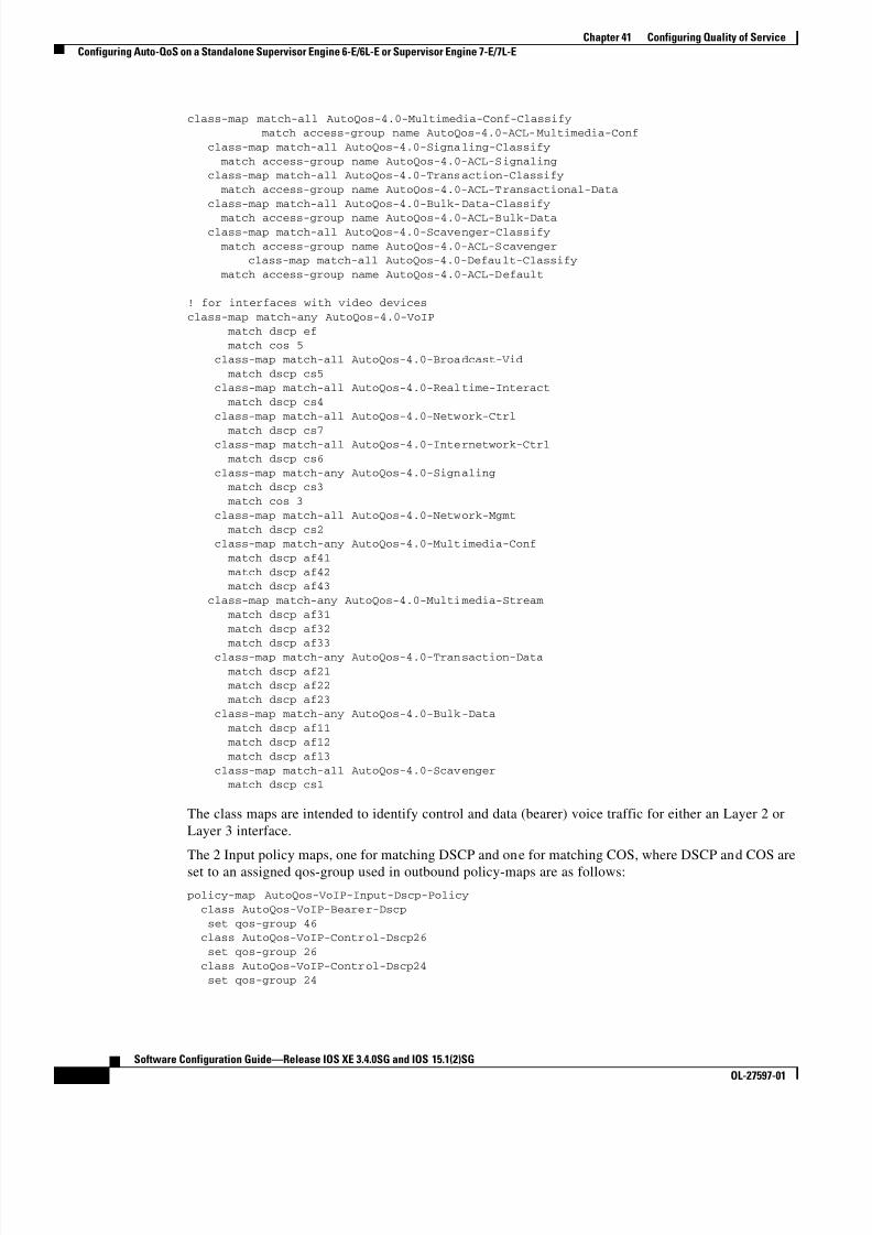
8/11/2019 7 L-Eqos_mrg
http://slidepdf.com/reader/full/7-l-eqosmrg 88/94
41-88
Software Configuration Guide—Release IOS XE 3.4.0SG and IOS 15.1(2)SG
OL-27597-01
Chapter 41 Configuring Quality of Service
Configuring Auto-QoS on a Standalone Supervisor Engine 6-E/6L-E or Supervisor Engine 7-E/7L-E
class-map match-all AutoQos-4.0-Multimedia-Conf-Classify match access-group name AutoQos-4.0-ACL-Multimedia-Conf
class-map match-all AutoQos-4.0-Signaling-Classify
match access-group name AutoQos-4.0-ACL-Signaling class-map match-all AutoQos-4.0-Transaction-Classify
match access-group name AutoQos-4.0-ACL-Transactional-Data
class-map match-all AutoQos-4.0-Bulk-Data-Classify
match access-group name AutoQos-4.0-ACL-Bulk-Data class-map match-all AutoQos-4.0-Scavenger-Classify
match access-group name AutoQos-4.0-ACL-Scavenger class-map match-all AutoQos-4.0-Default-Classify
match access-group name AutoQos-4.0-ACL-Default
! for interfaces with video devices
class-map match-any AutoQos-4.0-VoIP
match dscp ef match cos 5
class-map match-all AutoQos-4.0-Broadcast-Vid
match dscp cs5 class-map match-all AutoQos-4.0-Realtime-Interact
match dscp cs4
class-map match-all AutoQos-4.0-Network-Ctrl
match dscp cs7 class-map match-all AutoQos-4.0-Internetwork-Ctrl
match dscp cs6
class-map match-any AutoQos-4.0-Signaling match dscp cs3
match cos 3
class-map match-all AutoQos-4.0-Network-Mgmt
match dscp cs2 class-map match-any AutoQos-4.0-Multimedia-Conf
match dscp af41
match dscp af42 match dscp af43
class-map match-any AutoQos-4.0-Multimedia-Stream
match dscp af31
match dscp af32 match dscp af33
class-map match-any AutoQos-4.0-Transaction-Data
match dscp af21 match dscp af22
match dscp af23
class-map match-any AutoQos-4.0-Bulk-Data
match dscp af11 match dscp af12
match dscp af13
class-map match-all AutoQos-4.0-Scavenger match dscp cs1
The class maps are intended to identify control and data (bearer) voice traffic for either an Layer 2 or
Layer 3 interface.
The 2 Input policy maps, one for matching DSCP and one for matching COS, where DSCP and COS are
set to an assigned qos-group used in outbound policy-maps are as follows:
policy-map AutoQos-VoIP-Input-Dscp-Policy
class AutoQos-VoIP-Bearer-Dscp
set qos-group 46 class AutoQos-VoIP-Control-Dscp26
set qos-group 26
class AutoQos-VoIP-Control-Dscp24 set qos-group 24
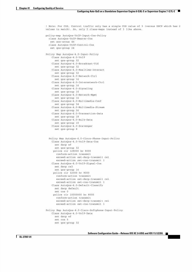
8/11/2019 7 L-Eqos_mrg
http://slidepdf.com/reader/full/7-l-eqosmrg 89/94
41-89
Software Configuration Guide—Release IOS XE 3.4.0SG and IOS 15.1(2)SG
OL-27597-01
Chapter 41 Configuring Quality of Service
Configuring Auto-QoS on a Standalone Supervisor Engine 6-E/6L-E or Supervisor Engine 7-E/7L-E
! Note: For COS, Control traffic only has a single COS value of 3 (versus DSCP which has 2values to match). So, only 2 class-maps instead of 3 like above.
policy-map AutoQos-VoIP-Input-Cos-Policy class AutoQos-VoIP-Bearer-Cos
set qos-group 46
class AutoQos-VoIP-Control-Cos
set qos-group 24
Policy Map AutoQos-4.0-Input-Policy Class AutoQos-4.0-VoIP
set qos-group 32
Class AutoQos-4.0-Broadcast-Vid set qos-group 32
Class AutoQos-4.0-Realtime-Interact
set qos-group 32 Class AutoQos-4.0-Network-Ctrl
set qos-group 16
Class AutoQos-4.0-Internetwork-Ctrl
set qos-group 16 Class AutoQos-4.0-Signaling
set qos-group 16
Class AutoQos-4.0-Network-Mgmt set qos-group 16
Class AutoQos-4.0-Multimedia-Conf
set qos-group 34 Class AutoQos-4.0-Multimedia-Stream
set qos-group 26
Class AutoQos-4.0-Transaction-Data
set qos-group 18 Class AutoQos-4.0-Bulk-Data
set qos-group 10
Class AutoQos-4.0-Scavenger set qos-group 8
Policy Map AutoQos-4.0-Cisco-Phone-Input-Policy Class AutoQos-4.0-VoIP-Data-Cos
set dscp ef
set qos-group 32 police cir 128000 bc 8000
conform-action transmit
exceed-action set-dscp-transmit cs1
exceed-action set-cos-transmit 1 Class AutoQos-4.0-VoIP-Signal-Cos
set dscp cs3
set qos-group 16 police cir 32000 bc 8000
conform-action transmit
exceed-action set-dscp-transmit cs1 exceed-action set-cos-transmit 1
Class AutoQos-4.0-Default-Classify
set dscp default
set cos 0 police cir 10000000 bc 8000
conform-action transmit exceed-action set-dscp-transmit cs1
exceed-action set-cos-transmit 1
Policy Map AutoQos-4.0-Cisco-Softphone-Input-Policy
Class AutoQos-4.0-VoIP-Data
set dscp ef set cos 5
set qos-group 32

8/11/2019 7 L-Eqos_mrg
http://slidepdf.com/reader/full/7-l-eqosmrg 90/94
41-90
Software Configuration Guide—Release IOS XE 3.4.0SG and IOS 15.1(2)SG
OL-27597-01
Chapter 41 Configuring Quality of Service
Configuring Auto-QoS on a Standalone Supervisor Engine 6-E/6L-E or Supervisor Engine 7-E/7L-E
police cir 128000 bc 8000 conform-action transmit
exceed-action set-dscp-transmit cs1
exceed-action set-cos-transmit 1 Class AutoQos-4.0-VoIP-Signal
set dscp cs3
set cos 3
set qos-group 16 police cir 32000 bc 8000
conform-action transmit exceed-action set-dscp-transmit cs1
exceed-action set-cos-transmit 1
Class AutoQos-4.0-Multimedia-Conf-Classify set dscp af41
set cos 4
set qos-group 34 police cir 5000000 bc 8000
conform-action transmit
exceed-action drop Class AutoQos-4.0-Signaling-Classify
set dscp cs3
set cos 3
set qos-group 16 police cir 32000 bc 8000
conform-action transmit
exceed-action drop Class AutoQos-4.0-Transaction-Classify
set dscp af21
set cos 2
set qos-group 18 police cir 10000000 bc 8000
conform-action transmit
exceed-action set-dscp-transmit cs1 exceed-action set-cos-transmit 1
Class AutoQos-4.0-Bulk-Data-Classify
set dscp af11
set cos 1 set qos-group 10
police cir 10000000 bc 8000
conform-action transmit exceed-action set-dscp-transmit cs1
exceed-action set-cos-transmit 1
Class AutoQos-4.0-Scavenger-Classify
set dscp cs1 set cos 1
set qos-group 8
police cir 10000000 bc 8000 conform-action transmit
exceed-action drop
Class AutoQos-4.0-Default-Classify set dscp default
set cos 0
Policy Map AutoQos-4.0-Classify-Input-Policy Class AutoQos-4.0-Multimedia-Conf-Classify
set dscp af41 set cos 4
set qos-group 34
Class AutoQos-4.0-Signaling-Classify set dscp cs3
set cos 3
set qos-group 16 Class AutoQos-4.0-Transaction-Classify
set dscp af21

8/11/2019 7 L-Eqos_mrg
http://slidepdf.com/reader/full/7-l-eqosmrg 91/94
41-91
Software Configuration Guide—Release IOS XE 3.4.0SG and IOS 15.1(2)SG
OL-27597-01
Chapter 41 Configuring Quality of Service
Configuring Auto-QoS on a Standalone Supervisor Engine 6-E/6L-E or Supervisor Engine 7-E/7L-E
set cos 2 set qos-group 18
Class AutoQos-4.0-Bulk-Data-Classify
set dscp af11 set cos 1
set qos-group 10
Class AutoQos-4.0-Scavenger-Classify
set dscp cs1 set cos 1
set qos-group 8 Class AutoQos-4.0-Default-Classify
set dscp default
set cos 0
The class maps used for Output matching are as follows:
! Since we assigned matched traffic to a qos-group on input,
! we only need to match the qos-group on output
! Note: Any other traffic not matched on input and assigned to a qos-group goes into the
class-default queue
! for control traffic (CS3 and AF31)
class-map match-all AutoQos-VoIP-Control-QosGroup24
match qos-group 24
class-map match-all AutoQos-VoIP-Control-QosGroup26 match qos-group 26
! For phone to phone (Bearer EF) trafficclass-map match-all AutoQos-VoIP-Bearer-QosGroup
match qos-group 46
! For softphone
Class Map match-any AutoQos-4.0-Scavenger-Queue (id 24)
Match qos-group 8
Match dscp cs1 (8)
Class Map match-all AutoQos-4.0-Priority-Queue (id 3)
Match qos-group 32
Class Map match-all AutoQos-4.0-Control-Mgmt-Queue (id 28)
Match qos-group 16
Class Map match-all AutoQos-4.0-Multimedia-Conf-Queue (id 10)
Match qos-group 34
Class Map match-all AutoQos-4.0-Multimedia-Stream-Queue (id 5)
Match qos-group 26
Class Map match-all AutoQos-4.0-Trans-Data-Queue (id 30)
Match qos-group 18
Class Map match-all AutoQos-4.0-Bulk-Data-Queue (id 17)
Match qos-group 10

8/11/2019 7 L-Eqos_mrg
http://slidepdf.com/reader/full/7-l-eqosmrg 92/94
41-92
Software Configuration Guide—Release IOS XE 3.4.0SG and IOS 15.1(2)SG
OL-27597-01
Chapter 41 Configuring Quality of Service
Configuring Auto-QoS on a Standalone Supervisor Engine 6-E/6L-E or Supervisor Engine 7-E/7L-E
Note The previous section listing defines the AutoQoS macros for defining QoS guidelines prior to Solution
Reference Network Design 4.0 (SRND4). Starting with Cisco Release XE 3.3.0(SG) and 15.1(1)SG, the
Catalyst 4500 Series Switch supports the auto qos srnd4 command.
The following classes are required and generated by all SRND4 CLIs.class-map match-all AutoQos-4.0-Priority-Queue
match qos-group 32
class-map match-all AutoQos-4.0-Control-Mgmt-Queue match qos-group 16
class-map match-all AutoQos-4.0-Multimedia-Conf-Queue
match qos-group 34 class-map match-all AutoQos-4.0-Multimedia-Stream-Queue
match qos-group 26
class-map match-all AutoQos-4.0-Trans-Data-Queue match qos-group 18
class-map match-all AutoQos-4.0-Bulk-Data-Queue
match qos-group 10 class-map match-any AutoQos-4.0-Scavenger-Queue
match qos-group 8
match dscp cs1
The output policy maps are as follows:
! Each class maps to a different qos-group with
! class-default taking any traffic not assigned to a qos-group
! Note: in this example, the outbound policy map drops voice packets when the priorityqueue exceeds 33% utilization of the link. Each deployment must establish their own upper
bound for voice packets.
policy-map AutoQos-VoIP-Output-Policy
class AutoQos-VoIP-Bearer-QosGroup
set dscp ef
set cos 5
priority police cir percent 33
class AutoQos-VoIP-Control-QosGroup26 set dscp af31
set cos 3
bandwidth remaining percent 5
class AutoQos-VoIP-Control-QosGroup24 set dscp cs3
set cos 3
bandwidth remaining percent 5 class class-default
dbl
Note There are no default cos-to-dscp or dscp-to-cos mappings on the. Values must be explicitly set
for trunks.
Policy Map AutoQos-4.0-Output-Policy Class AutoQos-4.0-Scavenger-Queue
bandwidth remaining percent 1
Class AutoQos-4.0-Priority-Queue priority
police cir percent 30 bc 33 ms
conform-action transmit
exceed-action drop Class AutoQos-4.0-Control-Mgmt-Queue
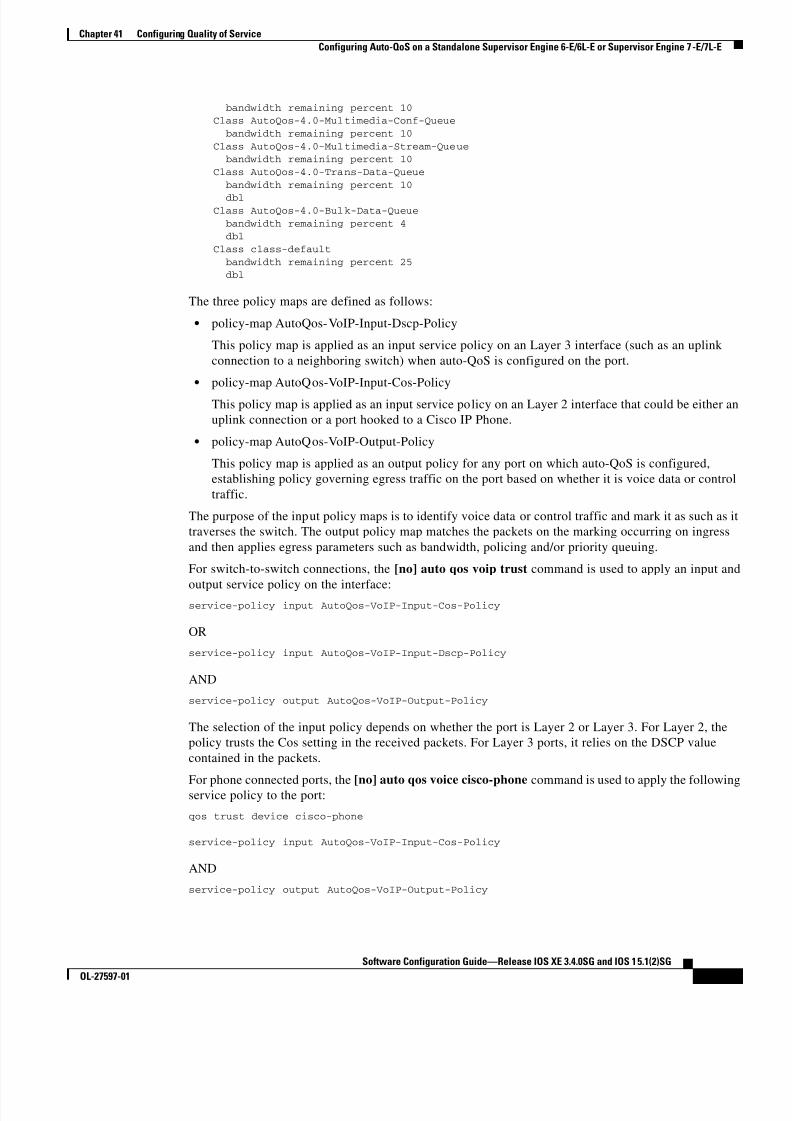
8/11/2019 7 L-Eqos_mrg
http://slidepdf.com/reader/full/7-l-eqosmrg 93/94
41-93
Software Configuration Guide—Release IOS XE 3.4.0SG and IOS 15.1(2)SG
OL-27597-01
Chapter 41 Configuring Quality of Service
Configuring Auto-QoS on a Standalone Supervisor Engine 6-E/6L-E or Supervisor Engine 7-E/7L-E
bandwidth remaining percent 10 Class AutoQos-4.0-Multimedia-Conf-Queue
bandwidth remaining percent 10
Class AutoQos-4.0-Multimedia-Stream-Queue bandwidth remaining percent 10
Class AutoQos-4.0-Trans-Data-Queue
bandwidth remaining percent 10
dbl Class AutoQos-4.0-Bulk-Data-Queue
bandwidth remaining percent 4 dbl
Class class-default
bandwidth remaining percent 25 dbl
The three policy maps are defined as follows:
• policy-map AutoQos-VoIP-Input-Dscp-Policy
This policy map is applied as an input service policy on an Layer 3 interface (such as an uplink
connection to a neighboring switch) when auto-QoS is configured on the port.
• policy-map AutoQos-VoIP-Input-Cos-Policy
This policy map is applied as an input service policy on an Layer 2 interface that could be either an
uplink connection or a port hooked to a Cisco IP Phone.
• policy-map AutoQos-VoIP-Output-Policy
This policy map is applied as an output policy for any port on which auto-QoS is configured,
establishing policy governing egress traffic on the port based on whether it is voice data or control
traffic.
The purpose of the input policy maps is to identify voice data or control traffic and mark it as such as it
traverses the switch. The output policy map matches the packets on the marking occurring on ingress
and then applies egress parameters such as bandwidth, policing and/or priority queuing.
For switch-to-switch connections, the [no] auto qos voip trust command is used to apply an input and
output service policy on the interface:service-policy input AutoQos-VoIP-Input-Cos-Policy
OR
service-policy input AutoQos-VoIP-Input-Dscp-Policy
AND
service-policy output AutoQos-VoIP-Output-Policy
The selection of the input policy depends on whether the port is Layer 2 or Layer 3. For Layer 2, the
policy trusts the Cos setting in the received packets. For Layer 3 ports, it relies on the DSCP value
contained in the packets.
For phone connected ports, the [no] auto qos voice cisco-phone command is used to apply the followingservice policy to the port:
qos trust device cisco-phone
service-policy input AutoQos-VoIP-Input-Cos-Policy
AND
service-policy output AutoQos-VoIP-Output-Policy

8/11/2019 7 L-Eqos_mrg
http://slidepdf.com/reader/full/7-l-eqosmrg 94/94
Chapter 41 Configuring Quality of Service
Configuring Auto-QoS on a Standalone Supervisor Engine 6-E/6L-E or Supervisor Engine 7-E/7L-E
It establishes a trusted boundary that recognizes Cisco IP Phones and trusts the Cos setting of the packets
from the phone. If a Cisco IP Phone is not detected, the Cos field is ignored and the packets are not
classified as voice traffic. Upon detecting a Cisco phone, the ingress packets are marked based on the
Cos value in the packets. This marking is used on egress for proper traffic classification and handling.
Auto qos srnd4—Is generated when any new auto qos command is configured on an interface and
migrates from legacy CLIs to generate new configurations. This CLI only generates a globalconfiguration if during migration, one or more interfaces has legacy auto-QoS enabled
Auto qos video—Generates QoS configuration for untrusted interfaces. It incorporates a service-policy
to classify the traffic coming from untrusted desktops/devices and marks them accordingly.
Auto qos void cisco-softphone—Generate QoS configuration for interfaces connected to PCs running
the Cisco IP SoftPhone application and marks as police traffic stemming from such interfaces. Ports
configured with this CLI are considered untrusted.
Auto qos classify—Generates QoS configuration for untrusted interfaces. It applies a service-policy to
classify the traffic stemming from untrusted desktops or devices and marks them accordingly. The
service-policies generated do not police.


![D 4E 7 .3- % + $ I4J$ :L]$ + 9 O - - L 3888 < 7 D · 2016-06-28 · d 4e 7 .3- 0 7 "o - - l 7 d ' @ - ' & -? )$ ? ) ?$ 2 # + 9 " , + l ?. + 9 o? 9 + :7?!0ld88 c $ 9 + 34 ? 558d0558ae5678f\](https://img.pdfslide.us/doc/110x75/5ec7d4c996f739304365ba87/d-4e-7-3-i4j-l-9-o-l-3888-7-d-2016-06-28-d-4e-7-3-0-7.jpg)


![6$)(7< '$7$ 6+((7 DFFRUGLQJ WR 5HJXODWLRQ (& 1R ^ ] l W](https://img.pdfslide.us/doc/110x75/61e42f2725519c7db92f725a/67lt-7-67-dffruglqj-wr-5hjxodwlrq-amp-1r-l-w-.jpg)