Embed Size (px)
Citation preview
7 Hints That Every Engineer Should Know When Making Power Measurements with Oscilloscopes.
Achieving maximized measurement dynamic range 1) Use averaging to increase measurement resolution 2) Use high-resolution acquisition to increase measurement resolution 3) Use AC coupling to remove DC offset 4) Bandwidth limiting with the oscilloscope and probes
Probing to optimize signal integrity 5) Use differential probes for safe and accurate floating measurement 6) Avoid probing accessories that couple radiated power 7) Select probes that avoid the scope’s most sensitive settings
2
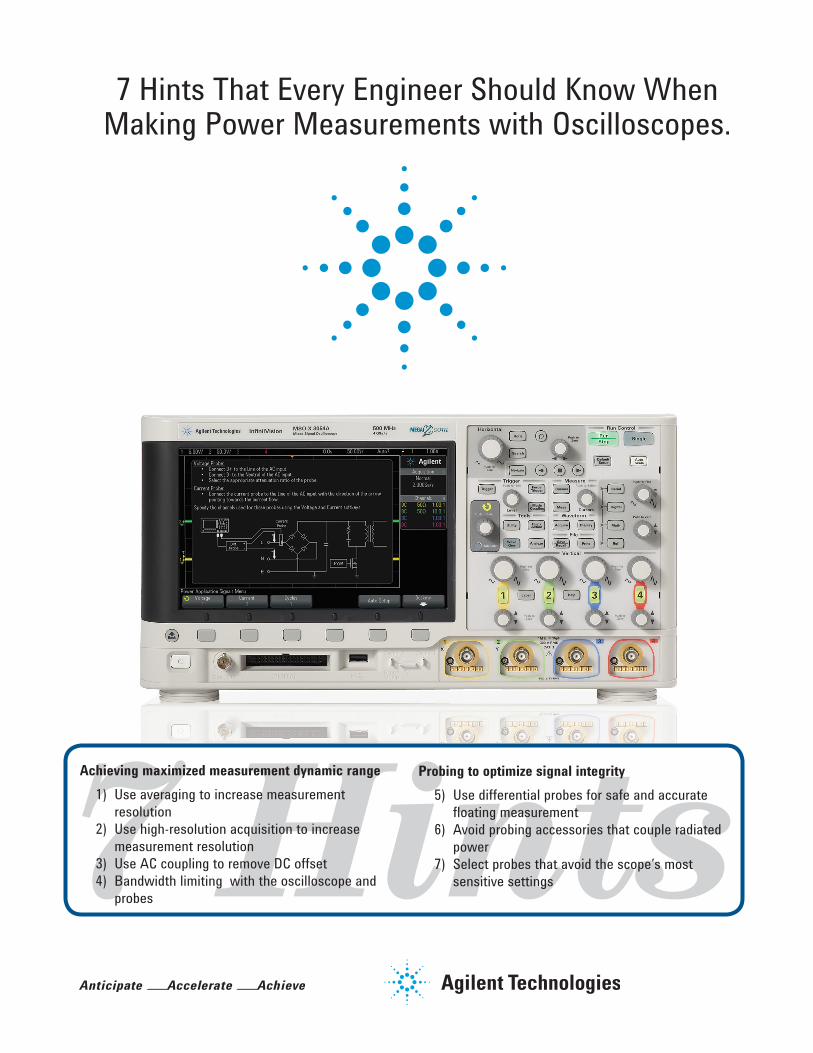
For some power-measurement applications, you need to measure a large dynamic range of values; and at the same time you need fine resolution to measure small changes in a parameter. Rather than resorting to a high-resolution digitizer, you can use alternative acquisition methods to reduce random noise and increase the effective dynamic range of your measurements. Two methods are average and high-resolution acquisition.
Averaging requires a repetitive signal. The algorithm works by averaging the points in each time bucket across multiple acquisitions. This reduces random noise, and gives you better vertical resolution.
How many averages are needed per extra bit of vertical resolution? You get one extra bit of vertical resolution for every four averages of the samples. It works like this:
• Numberofbitsincreased=0.5log2N • N=thenumberofsamplesaveraged • For example, averaging 16 samples will yield an improvement of: • Numberofbits=0.5log216=2 • Therefore, the effective vertical resolution is 8 + 2 = 10 bits.
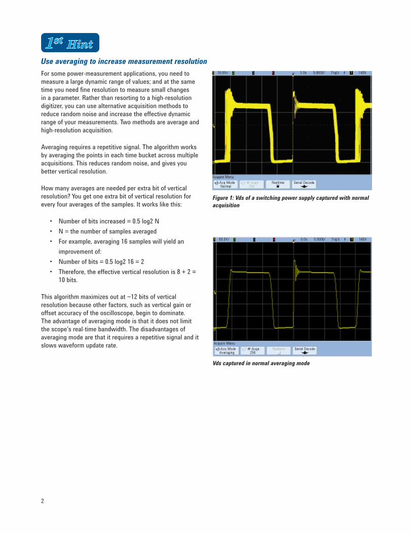
This algorithm maximizes out at ~12 bits of vertical resolution because other factors, such as vertical gain or offset accuracy of the oscilloscope, begin to dominate. The advantage of averaging mode is that it does not limit the scope’s real-time bandwidth. The disadvantages of averaging mode are that it requires a repetitive signal and it slows waveform update rate.
Figure 1: Vds of a switching power supply captured with normal acquisition
Vds captured in normal averaging mode
Use averaging to increase measurement resolution
3
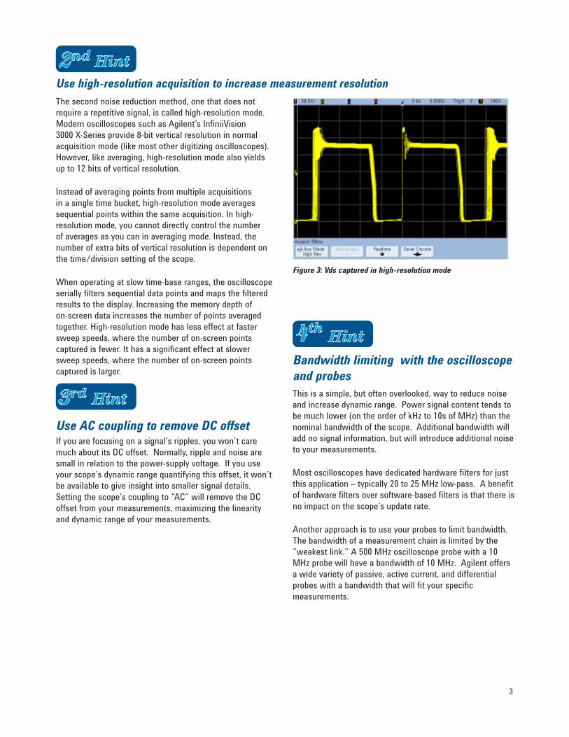
Use high-resolution acquisition to increase measurement resolutionThe second noise reduction method, one that does not require a repetitive signal, is called high-resolution mode. Modern oscilloscopes such as Agilent’s InfiniiVision 3000 X-Series provide 8-bit vertical resolution in normal acquisition mode (like most other digitizing oscilloscopes). However, like averaging, high-resolution mode also yields up to 12 bits of vertical resolution.
Instead of averaging points from multiple acquisitions in a single time bucket, high-resolution mode averages sequential points within the same acquisition. In high-resolution mode, you cannot directly control the number of averages as you can in averaging mode. Instead, the number of extra bits of vertical resolution is dependent on the time/division setting of the scope.
When operating at slow time-base ranges, the oscilloscope serially filters sequential data points and maps the filtered results to the display. Increasing the memory depth of on-screen data increases the number of points averaged together. High-resolution mode has less effect at faster sweep speeds, where the number of on-screen points captured is fewer. It has a significant effect at slower sweep speeds, where the number of on-screen points captured is larger.
Figure 3: Vds captured in high-resolution mode
Use AC coupling to remove DC offsetIf you are focusing on a signal’s ripples, you won’t care muchaboutitsDCoffset.Normally,rippleandnoisearesmall in relation to the power-supply voltage. If you use your scope’s dynamic range quantifying this offset, it won’t be available to give insight into smaller signal details. Setting the scope’s coupling to “AC” will remove the DC offset from your measurements, maximizing the linearity and dynamic range of your measurements.
Bandwidth limiting with the oscilloscope and probesThis is a simple, but often overlooked, way to reduce noise and increase dynamic range. Power signal content tends to be much lower (on the order of kHz to 10s of MHz) than the nominal bandwidth of the scope. Additional bandwidth will add no signal information, but will introduce additional noise to your measurements.
Most oscilloscopes have dedicated hardware filters for just this application – typically 20 to 25 MHz low-pass. A benefit of hardware filters over software-based filters is that there is no impact on the scope’s update rate.
Another approach is to use your probes to limit bandwidth. The bandwidth of a measurement chain is limited by the “weakest link.” A 500 MHz oscilloscope probe with a 10 MHz probe will have a bandwidth of 10 MHz. Agilent offers a wide variety of passive, active current, and differential probes with a bandwidth that will fit your specific measurements.
4
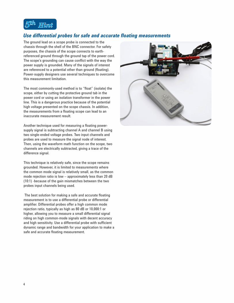
Use differential probes for safe and accurate floating measurementsThe ground lead on a scope probe is connected to the chassisthroughtheshelloftheBNCconnector.Forsafetypurposes, the chassis of the scope connects to earth-referenced ground through the ground tap of the power cord. The scope’s grounding can cause conflict with the way the power supply is grounded. Many of the signals of interest are referenced to a potential other than ground (floating). Power-supply designers use several techniques to overcome this measurement limitation.
The most commonly-used method is to “float” (isolate) the scope, either by cutting the protective ground tab in the power cord or using an isolation transformer in the power line. This is a dangerous practice because of the potential high voltage presented on the scope chassis. In addition, the measurements from a floating scope can lead to an inaccurate measurement result.
Another technique used for measuring a floating power-supply signal is subtracting channel A and channel B using two single-ended voltage probes. Two input channels and probes are used to measure the signal node of interest. Then, using the waveform math function on the scope, two channels are electrically subtracted, giving a trace of the difference signal.
This technique is relatively safe, since the scope remains grounded. However, it is limited to measurements where the common mode signal is relatively small, as the common mode rejection ratio is low – approximately less than 20 dB (10:1) -because of the gain mismatches between the two probes input channels being used.
The best solution for making a safe and accurate floating measurement is to use a differential probe or differential amplifier. Differential probes offer a high common mode rejection ratio, typically as high as 80 dB or 10,000:1 or higher, allowing you to measure a small differential signal riding on high common-mode signals with decent accuracy and high sensitivity. Use a differential probe with sufficient dynamic range and bandwidth for your application to make a safe and accurate floating measurement.
5
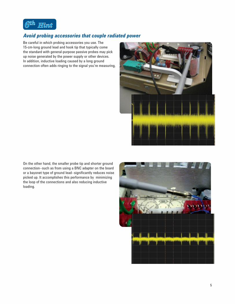
Avoid probing accessories that couple radiated powerBe careful in which probing accessories you use. The 15-cm-long ground lead and hook tip that typically come the standard with general-purpose passive probes may pick up noise generated by the power supply or other devices. In addition, inductive loading caused by a long ground connection often adds ringing to the signal you’re measuring,
On the other hand, the smaller probe tip and shorter ground connection--suchasfromusingaBNCadapterontheboardor a bayonet type of ground lead--significantly reduces noise picked up. It accomplishes this performance by minimizing the loop of the connections and also reducing inductive loading.
6
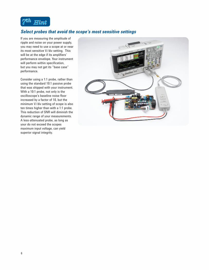
Select probes that avoid the scope’s most sensitive settingsIf you are measuring the amplitude of ripple and noise on your power supply, you may need to use a scope at or near its most sensitive V/div setting. This will be at the edge if its amplifiers’ performance envelope. Your instrument will perform within specification, but you may not get its “base case” performance. Consider using a 1:1 probe, rather than using the standard 10:1 passive probe that was shipped with your instrument. With a 10:1 probe, not only is the oscilloscope’s baseline noise floor increased by a factor of 10, but the minimum V/div setting of scope is also ten times higher than with a 1:1 probe. ThisreductionofSNRwilldiminishthedynamic range of your measurements. A less-attenuated probe, as long as your do not exceed the scopes maximum input voltage, can yield superior signal integrity.
7
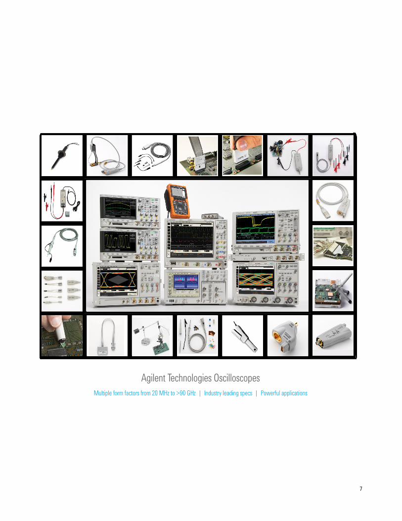
Agilent Technologies OscilloscopesMultiple form factors from 20 MHz to >90 GHz | Industry leading specs | Powerful applications
Windows® is a U.S. registered trademark of Microsoft Corporation.
Agilent Advantage Services is committed to your success throughout your equip-ment’s lifetime. To keep you competitive, we continually invest in tools and processes that speed up calibration and repair and reduce your cost of ownership. You can also use Infoline Web Services to manage equipment and services more effectively. By sharing our measurement and service expertise, we help you create the products that change our world.
www.agilent.com/quality
www.agilent.com/find/advantageservices
Quality Management SystemQuality Management SysISO 9001:2008Agilent Electronic Measurement Group
DEKRA Certified
www.agilent.comwww.agilent.com/find/power-meas
For more information on Agilent Tech-nologies’ products, applications or services, please contact your local Agilent office. The complete list is available at:www.agilent.com/find/contactus
AmericasCanada (877) 894 4414 Brazil (11) 4197 3600Mexico 01800 5064 800 United States (800) 829 4444
Asia PacificAustralia 1 800 629 485China 800 810 0189Hong Kong 800 938 693India 1 800 112 929Japan 0120 (421) 345Korea 080 769 0800Malaysia 1 800 888 848Singapore 1 800 375 8100Taiwan 0800 047 866Other AP Countries (65) 375 8100
Europe & Middle EastBelgium 32 (0) 2 404 93 40 Denmark 45 45 80 12 15Finland 358 (0) 10 855 2100France 0825 010 700* *0.125 €/minuteGermany 49 (0) 7031 464 6333 Ireland 1890 924 204Israel 972-3-9288-504/544Italy 39 02 92 60 8484Netherlands 31(0)205472111Spain 34 (91) 631 3300Sweden 0200-88 22 55United Kingdom 44 (0) 118 927 6201For other unlisted countries: www.agilent.com/find/contactusRevised: January 6, 2012
Product specifications and descriptions in this document subject to change without notice.
© Agilent Technologies, Inc. 2011, 2012Published in USA, March 21, 20125990-9340EN
Agilent Email Updates
www.agilent.com/find/emailupdatesGet the latest information on the products and applications you select.
www.lxistandard.orgLANeXtensionsforInstrumentsputsthe power of Ethernet and the Webinside your test systems. Agilent is a founding member of the LXI consor-tium.
Agilent Channel Partnerswww.agilent.com/find/channelpartnersGet the best of both worlds: Agilent’s measurement expertise and product breadth, combined with channel partner convenience.
www.axiestandard.org AdvancedT-CA® Extensions for Instrumentation and Test (AXIe) is an open standard that extends the AdvancedTCA for general purpose and semiconductor test. Agilent is a founding member of the AXIe consortium.
www.pxisa.org PCI eXtensions for Instrumentation (PXI) modular instrumentationdelivers a rugged, PC-based high-per-formance measurement and automa-tion system.
TM