Embed Size (px)
Citation preview
224
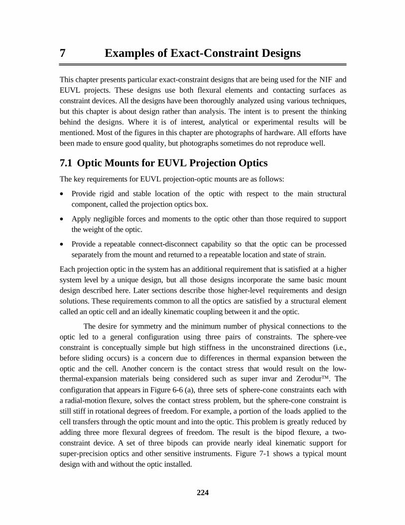
7 Examples of Exact-Constraint Designs
This chapter presents particular exact-constraint designs that are being used for the NIF andEUVL projects. These designs use both flexural elements and contacting surfaces asconstraint devices. All the designs have been thoroughly analyzed using various techniques,but this chapter is about design rather than analysis. The intent is to present the thinkingbehind the designs. Where it is of interest, analytical or experimental results will bementioned. Most of the figures in this chapter are photographs of hardware. All efforts havebeen made to ensure good quality, but photographs sometimes do not reproduce well.
7.1 Optic Mounts for EUVL Projection OpticsThe key requirements for EUVL projection-optic mounts are as follows:
• Provide rigid and stable location of the optic with respect to the main structuralcomponent, called the projection optics box.
• Apply negligible forces and moments to the optic other than those required to supportthe weight of the optic.
• Provide a repeatable connect-disconnect capability so that the optic can be processedseparately from the mount and returned to a repeatable location and state of strain.
Each projection optic in the system has an additional requirement that is satisfied at a highersystem level by a unique design, but all those designs incorporate the same basic mountdesign described here. Later sections describe those higher-level requirements and designsolutions. These requirements common to all the optics are satisfied by a structural elementcalled an optic cell and an ideally kinematic coupling between it and the optic.
The desire for symmetry and the minimum number of physical connections to theoptic led to a general configuration using three pairs of constraints. The sphere-veeconstraint is conceptually simple but high stiffness in the unconstrained directions (i.e.,before sliding occurs) is a concern due to differences in thermal expansion between theoptic and the cell. Another concern is the contact stress that would result on the low-thermal-expansion materials being considered such as super invar and Zerodur. The
configuration that appears in Figure 6-6 (a), three sets of sphere-cone constraints each witha radial-motion flexure, solves the contact stress problem, but the sphere-cone constraint isstill stiff in rotational degrees of freedom. For example, a portion of the loads applied to thecell transfers through the optic mount and into the optic. This problem is greatly reduced byadding three more flexural degrees of freedom. The result is the bipod flexure, a two-constraint device. A set of three bipods can provide nearly ideal kinematic support forsuper-precision optics and other sensitive instruments. Figure 7-1 shows a typical mountdesign with and without the optic installed.

7.1 Optic Mounts for EUVL Projection Optics
225
(a)
(b)
Figure 7-1 The optic cell and three bipod flexures (a) present three small kinematic couplings that engagethree lugs bonded to the optic (b). A coil spring held with a shoulder screw provides the preload for eachcoupling. The lugs are boned to the optic while attached to relaxed bipod flexures, and subsequently theassembly becomes matched for life. The individual three-tooth couplings are repeatable to the micron level.

Chapter 7 Examples of Exact-Constraint Design
226
While the decision to use three bipod flexures was fairly obvious and unconstrained,the opposite was true for the type of connection to make between each bipod and the optic.One design constraint was the need to order the optic substrate material before there wastime to design the mounts. This and the desire to keep the optics as simple as possible led tothe decision to epoxy bond mounting features to the semifinished optic that would arrivemonths later. The other primary decision was the type of connect-disconnect device to use ateach bipod. The sphere-cone constraint is simple and effective, but it comes with the riskthat significant noise moments can exist in the bipods depending how the optic is installedin the mount. A significant noise moment for these optics is a few newton-millimeters.Ultimately we chose to use the three-tooth coupling, a fully constraining connection. Thepositional repeatability of the coupling ensures very good elastic repeatability of theflexures. Further, the technique used to bond lugs to the optic puts the bipod flexures verynearly in a relaxed stress state.
The decisions made for this projection optics system, being a fast-track experimentaltool, are not necessarily appropriate for future production tools. For example, an issue withthe epoxy bond is long-term dimensional stability. Measurements of loaded samplesextrapolated in time indicate that the system may drift out of optical alignment in perhaps 6to 12 months (thus requiring an off-line realignment of optics).I This is obviously notacceptable for a production tool and the positional requirements probably will become morestringent in the future. It becomes apparent that future designs will require directconnections between the optic and the mount. An epoxy bond could be used as a fastener,for example, in conjunction with a compliant element to apply a preload, but the interfacethat determines stability should not be a polymer.
Given this insight, the sphere-cone constraint becomes a favorite because threecones are easily manufactured directly into the optic. The cell would present three smallspheres mounted on bipod flexures, for example. There are techniques available to make theoptic less sensitive to noise moments at the constraints, and the installation process can bemade more deterministic to reduce noise moments. In addition, there is no particularlimitation with this design from being able to process the optic in one cell and use it inanother. This would be very difficult to do with fully constraining couplings. Other aspectsmay also come into play such as combining actuated alignment mechanisms within the opticmount. Presently the cells are manipulated by alignment mechanisms, but it is difficult toachieve the very high resonance frequencies desired for such systems with a seriesarrangement of constraints.
I Experiments were performed at the University of North Carolina Charlotte [Patterson, et al., 1998] andLLNL.

227
7.2 A Gravity-Compensating Optic Mount for EUVLThree of the projection optics are manufactured using vertical-axis fabrication metrology tomatch the orientation of the projection optics system. These optics will have the properfigure when mounted rather than in the free state, assuming of course that the mount isabsolutely repeatable. One optic in the system is an exception because its large radius ofcurvature makes a vertical-axis interferometer impractical. With the optic supported in asling, horizontal fabrication metrology produces an optic with the proper figure nearer thefree state, especially when using multi-step averaging. It then becomes necessary tocompensate for the different mount and the change in gravity orientation.
A finite element model of the optic supported at three perimeter points, as with threebipods, revealed unacceptable gravity-induced figure error. Figure 7-2 (a) shows the figureerror within the clear aperture after removing the best-fit sphere.I The dominant error istrifoil produced from the three supports. By distributing the weight over nine perimeterpoints, the error becomes primarily spherical, which the system will tolerate with a focusadjustment. The remaining nonspherical error in (b) is more than an order of magnitude lessthan in (a). For comparison, the P-V error goes from 1.62 nm to 0.107 nm and the rmserror goes from 0.314 nm to 0.027 nm.
-100
-50
0
50
100
-60
-40
-20
0
20
40-10
-5
0
5
10
x 10-7
x-axisy-axis-100
-50
0
50
100
-40
-30
-20
-10
0
10
20
30
40-10
-5
0
5
x 10-8
x-axisy-axis
Figure 7-2 Figure error (in mm) over the clear aperture with three supports (a) and nine supports (b).
The gravity-compensating optic mount supports the weight of the optic at ninelocations around the perimeter. Three of the nine supports are rigid bipod constraints asused in the other three optic mounts. The remaining six supports are compliant springs thatprovide weight relief but no constraint. The tension is set according to modeling results thatminimize the nonspherical error over the clear aperture. Figure 7-3 shows the design for theprojection optics system in (a) and a demonstration test optic and mount in (b).
I Pro/MECHANICA by Parametric Technology Corp. is the finite element software used in this study.MATLAB by The MathWorks, Inc. is the computing environment used to process the finite-elementresults and create the surface plots.
(b)(a)

Chapter 7 Examples of Exact-Constraint Design
228
(a)
(b)
Figure 7-3 The gravity-compensating optic mount supports the weight of the optic at nine locationsaround the perimeter using three rigid bipod constraints and six compliant springs. The model in (a) is thedesign for the projection optics system. A demonstration test optic and mount appear in (b).

229
7.3 θθθθx-θθθθy-Z Flexure Stage for EUVL Projection OpticsI
Two of the projection optics require remotely actuated alignment degrees of freedom in θx,θy and z, where z is the optical axis. This out-of-plane motion may be accomplished by
translating any three perimeter points appropriately in the z direction. Effectively, these threetranslations are adjustable constraints. Three more passive constraints provide exactconstraint for the suspended object, in this case for the optic cell. Although a 3-2-1constraint arrangement is possible, the natural choice is three identical pairs of constraints,where one direction is actuated and the other is passive. This is the arrangement shown inFigure 7-4 for a prototypical optic, cell and actuation system.
Figure 7-4 Three sets of actuation flexures support the optic cell relative to a base plate. Each actuationflexure transfers radial motion from a piezo-driven screw to axial (z) motion of the cell through a 5:1reduction ratio. The cell then supports the optic passively through three bipod flexures.
The actuation system consists of three actuation flexures that support the optic cellrelative to the projection optics box and a set of three piezo-driven screws that actuate theflexures. The actuation flexure provides both passive constraint tangent to the cell and a 5:1transmission ratio between the screw and z motion at the cell. The screw provides the
I This material was previously published in greater detail [Tajbakhsh, et al., 1998].

Chapter 7 Examples of Exact-Constraint Design
230
actuated constraint through the 5:1 reduction ratio, thereby providing better resolution to thecell. Figure 7-5 shows more clearly the functional parts of the actuation system and theflexure cuts that provide the necessary freedoms.
(a) (b)
Figure 7-5 The actuation flexure consists of a supporting hinge flexure connected to a bipod. In (b), the5:1 lever ratio is more apparent between horizontal motion of the screw and vertical motion of the cell.
The actuation flexure is physically one piece of super invar that has been cut out asshown using wire EDM (electro-discharge machining). Functionally, it consists of theconstraint side that attaches to the cell and a transmission side that connects to the basestructure. The constraint flexure is the same basic bipod design that is used for opticmounts. It provides local angular freedom to the cell while transferring two constraints fromthe transmission flexure. The instant center (where the two constraints intersect) is placed inthe plane of the optic so that the rotation axis will also be in this plane. The transmissionflexure is a simple hinge axis that is controlled by the screw position. A subtle aspect is theangle of the blade whose plane intersects the instant center of the constraint flexure.Effectively the forces in the bipod flexure transfer to the transmission flexure through thispoint. If the screw also acts through this point, then there is no out-of-plane force on theblades. The angle of the plane defined by the hinge axis and the instant center determinesthe transmission ratio between the screw and the cell.
There are two main design issues with this actuation flexure. The first is the momentimparted to the cell during actuation. This could be alleviated by placing the hinge pointadjacent to the instant center, but this would require a cross flexure rather than a simplehinge. The finite element model shows no problems with this design because the cell is

7.3 θθθθ x-θθθθ y-Z Flexure Stage for EUVL Projection Optics
231
sufficiently stiff. It would become a problem if the cell were eliminated in a future designwith the optic directly supported on actuation flexures. The second issue is bendingcompliance in the transmission side since much of its structure lies outside the planebetween the hinge axis and the instant center. This is the main compliance in the prototypesystem whose first constrained mode is 133 Hz. In an effort to push towards 200 Hz, thetransmission side is now substantially thicker and joined across the legs.
It is interesting to state some of the experimental results of the prototype system. Asmentioned the first constrained mode is 133 Hz, but it is remarkable and perhapscoincidental that FEA and experimental modal analysis gave the same number. Actuallythere are two modes at this frequency corresponding to any two orthogonal translations inthe x-y plane. The remaining modal frequencies are 200 Hz and above. The dynamics of theoptic with respect to the cell is rather insignificant. The positioning resolution demonstratedby this system is 2 to 3 nanometers as determined by capacitance gauge feedback. Thescrews are controlled in a low-bandwidth loop until the final position is reached, then theyare turned off. All the main structural components are super invar except for thecommercially available piezo-driven screws.
7.4 X-Y Flexure Stage for EUVL Projection OpticsOne projection optic requires remotely actuated alignment degrees of freedom in x and y,where z is the optical axis. This optic is spherical and physically smaller than the other threeaspheric optics. Being spherical, it then is acceptable for the optic to rotate as it translates.This allows the possibility of a rotational axis being used to translate the optic. Beingsmaller, it becomes practical to build the alignment mechanism directly into the optic cell.The X-Y-θz stage that uses three folded-hinge flexures is a natural starting point for this
design (see Chapter 6.1.3). It merely requires one less actuated degree of freedom.
Figure 7-6 shows the design for the optic cell and integrated alignment mechanism.As with the other optics, three small bipod flexures support the optic relative to the cell. Thecell has three areas that attach directly to the projection optics box as indicated by mountingholes. The rest of the cell articulates on the flexures. For motion in the x-y plane, eachfolded-hinge flexure provides one actuated constraint along the constraint side of the flexure(using the same terminology as the previous section). The single flexure at the top providesone passive constraint in the x-y plane. The constraint lines for these flexures (indicated bycenterlines) form the instant centers about which the optic rotates. Extending actuator 1, forexample, moves the optic down and to the right. If both actuators extend equally, then theoptic translates downward without rotation. If both actuators extend equal amounts inopposite directions, then the optic rotates about the center of the passive constraint. The 30˚angle between the transmission and constraint flexures provides a 2:1 reduction ratiobetween the actuator and the constraint line. There is another reduction ratio ofapproximately 1.4:1 resulting from rotation about either instant center.

Chapter 7 Examples of Exact-Constraint Design
232
Instant Centerfor Actuator 2
Instant Centerfor Actuator 1
Actuator 1 Actuator 2
Ray Bundle
30°
Clear Aperture
(6) Mounting Holes
90°
Optic
(a)
(b)
Figure 7-6 In (a), a cross section through the optic cell shows the details of the flexures and the instantcenters about which the optic rotates. In (b), the optic cell interfaces to the interferometer through a three-vee coupling. The black ears with tooling balls are removed from the cell after interferometry is complete.

7.4 X-Y Flexure Stage for EUVL Projection Optics
233
The three out-of-plane degrees of freedom are overconstrained in this design by oneextra constraint. Each folded-hinge flexure provides one z constraint while the single flexureprovides two constraints, z and θy. The consequences of overconstraint will be some
residual stress in the cell, flexures and the supporting structure. Although the surfaces thatbolt together are precisely machined, they may require some hand fitting at assembly. Thisoverconstraint will not affect the freedom of motion in the x-y plane.
The modal frequencies as predicted by FEA are quite high for this design. The firstmode at 289 Hz results primarily from the flexibility of the folded-hinge flexures in theirpassive constraint direction. The next two modes are in the general direction of the actuatedmotions. Rotation about the passive constraint occurs at 354 Hz and translation (up anddown) occurs at 436 Hz.
7.5 Kinematic Mounts for NIF Optics AssembliesThe basic kinematics and the optimization analysis for this example are treated in Chapter 6.This section presents the design solution and explains the main decisions made through thedesign process. The key requirements for the NIF kinematic mounts are as follows:
• Provide stiff, repeatable location in six degrees of freedom.
• Allow straight-line installation of the assembly from underneath.
• Provide the maximum amount of clearance and capture range within the spaceconstraints of the closely packed laser beams.
• Provide secondary safety support and seismic restraint.
• Operate in accordance with class 100 clean room requirements.
The last two requirements are not discussed other than to say that a separate mechanismprovides seismic restraint, effectively holding the kinematic mounts together, and that all theparts are corrosion resistant and easy to clean. Since the operation is infrequent and themechanisms operate under essentially no load, particle generation is not expected to beproblem. The first three requirements govern the kinematic mount design described here.
The architecture for the NIF laser system is heavily influenced by the need toroutinely replace damaged optics in a very clean and inert atmosphere. A concept wasdeveloped where any optics assembly, known as a line replaceable unit or LRU, could beinstalled or removed from underneath the beam line of the laser.I The LRU being installedis transported in a clean canister from the clean assembly area to the beam line. The canisterdocks to the laser structure using a kinematic coupling, establishes a pressure-tight seal,
I As the design matured, some types of LRU’s were easier to load from the top or the side, but most stillload from below.

Chapter 7 Examples of Exact-Constraint Design
234
removes an access panel, and installs the LRU with a straight-line lift.I The interfacebetween the LRU and the canister lift platform is also kinematic and preloaded by gravity.II
Yet another kinematic coupling supports the LRU from the laser structure. This is thekinematic mount that must satisfy the requirements stated above. A prototype LRU forperiscope optics appears in Figure 7-7 along with close-up views of the kinematic mounts.
Figure 7-7 The prototype LRU in (a) is temporarily supported by a crane to better show the kinematicmounts. The LRU is over 2.5 m tall, and when mounted in the NIF periscope structure, the lowest pointwill be 3.6 m to 5.5 m above the floor. The upper mount has two pin-slot constraints like the one shownin (b) partially engaged. The pin attaches to the structure and is Ø 35 mm. In (c), two vee blocks on theLRU engage two Ø 32 mm actuated pins on the structure to form the lower mount.
I The kinematic coupling consists of three conical seats in the bottom of the laser structure and threespheres attached to the top of the canister each with a hinge axis to release the radial constraints. Theupward preload is provided by the transporter that carries the canister.II The bottom of the LRU has conical sockets that engage spheres on the canister lift platform each havingthe appropriate flexural freedom.
(a)
(b)
(c)

7.5 Kinematic Mounts for NIF Optics Assemblies
235
The upright shape and dense packing of LRU’s combined with demanding stabilityrequirements (0.6 µr rms at the optics from all sources) constrained the mounting points tolie in a vertical plane to give the most favorable aspect ratio. Further, FEA showed that thetorsional mode of the LRU frame would be a limitation to achieving the vibrational part ofthe stability budget. This assumes that the one end is torsionally constrained, say with twovees, and the other end is free to rotate about the third vee.I The modal frequency can beincreased somewhat by placing the instant center of the vee near the principal axis, therebyreducing the mode’s moment of inertia. This naturally leads to a widely spaced vee, whichhas the more significant benefit of adding a stiff, frictional constraint against rotation. Forexample, the stiffness of this frictional constraint is an order of magnitude stiffer than theLRU frame. On the other hand, tangential friction forces in the constraints could potentiallytwist the frame up to 40 µr from the free state, but this is much less than the requirement forinitial alignment. It is only important that the twist remains constant.
One very basic choice made early in the design process was to use gravity to preloadthe kinematic mount. Frankly, the alternative (a latching mechanism that would preload theLRU up against a passive kinematic coupling) was not explored as thoroughly as it shouldhave been. Either case requires a mechanism that allows a straight-line insertion fromunderneath and then restrains both gravity and potential seismic loads. In the beginning,probably not enough consideration was given to the seismic load. A mechanism that worksin concert with gravity would seem to be simpler than one that must defeat gravity. It is easyto become convinced this way when you have a workable concept in mind and have notcarefully thought through the alternatives. Another aspect that seems to favor a gravity-loaded kinematic mount is the freer transfer of the LRU from the canister lift platform, alsoa gravity-loaded kinematic coupling. The weight transfers in a smooth hand off from onecoupling to another as the platform rises or lowers.
The basic configuration of the LRU kinematic mount is a three-vee coupling withone widely spaced vee at the top and two vees near the bottom. The upper vee is passive withtwo pin-slot constraints that engage as the LRU lifts into place. The lower mount is activeand formed by two vee blocks on the LRU that can pass by retracted pins on the structure.The pins extend to receive the vee blocks and support the weight of the LRU. The details ofthese will be presented later. This design is an inversion of the original concept that had twoactuated pins mounted near the top of the LRU. There were differing opinions as to thebetter arrangement. The final decision was made by a fairly diverse group of twelve peopleusing the Analytic Hierarchy Process. The results through the first criteria level appear inTable 7-1. Some of the key factors in this decision were: 1) the preference to place potentialparticle generators below optics, 2) better personnel access in case the mechanism failed to
I Had there been space around the LRU, a reasonable approach would be to place three vees in a horizontalplane at the middle elevation. It still may have been difficult to meet the stability budget.

Chapter 7 Examples of Exact-Constraint Design
236
release, 3) avoid remotely breaking pneumatic lines between the LRU and the canister, and4) better capture range provided by a passive upper mount.
AHP Design SpreadsheetCreated by L. Hale 2/27/97
Decision: 1 0 1 0 1 0Criteria Level 1 > 1.00 Functionality Design Issues MaintenanceCriteria Level 2 > 0.33 0.33 0.33
Design OptionsActive mount location> LRU - upper 5 .23 3.62 6.26 6.32> LRU - lower 6 .77 3.91 7.94 10.00> Structure - upper 5 .01 3.83 7.88 4.16> Structure - lower 7 .42 5.54 10.00 7.37
Table 7-1 The AHP helps provide a global picture of the decision while focusing attention to specificdetails. The design options were evaluated at Criteria Level 2. These are: Loading, Centering andCleanliness under Functionality; Clearances, Seismic and Pneumatics under Design Issues; and Reliability,Release Access and Repair Access under Maintenance.
The pin-slot constraints of the upper mount provide a simple, passive engagementupon inserting the LRU into position. As Figure 7-8 shows, each constraint consists of atapered pin attached to the structure and a slotted receiver at the top of the LRU. Thecombination provides the top of the LRU with approximately 15 mm of radial capturerange. The upward-facing receiver also tends to catch any wear particles generated from thesiding surfaces. The vee angle formed by the slots was determined to optimize centeringability as discussed in Chapter 6. This angle varies among different types of LRU’s but theworse-case load governs the design of these parts that are in common. Managing the contactstress is the primary design problem for relatively heavy loads, and the need for capturerange makes it difficult to use closely conforming surfaces. After working through thecompromises, the results of the contact analysis appear in Table 7-2. The materials are thesame as used on the lower mount and will be discussed later.
Analysis for Upper Mount
Pin’s principal radii of curvature Rxx = 215 mm Ryy = 17.5 mm
Slot’s principal radii of curvature Rxx = 45 mm Ryy = inf. (straight)
Load cases: nominal and 4x nominal P = 90 kgf P = 4 (90) kgf
Contact pressure (compressive stress) p = 223 ksi p = 353 ksi
Maximum shear stress (no sliding) τ = 72.5 ksi τ = 115 ksi
Equivalent tensile stress σ = √3 τ σ = 125 ksi σ = 199 ksi
Approach of distant points δ = 11 µm δ = 27 µm
Stiffness at the nominal load k = 0.70 Mlb/in
Table 7-2 Two load cases are provided for the upper mount at full engagement. Four times the nominalload represents a dynamic overload that might occur in an earthquake. A nominal load at initial engagementhas nearly identical stress as the overload case.

7.5 Kinematic Mounts for NIF Optics Assemblies
237
Figure 7-8 The slotted receiver at the top of the LRU engages the tapered pin attached to the structure.
The lower active mount consists of right- and left-hand assemblies of identical parts.For example, Figure 7-9 shows the left-hand assembly. Each vee block bolts to the LRUwith the contact surfaces pointing down and towards the center. These surfaces are revolvedso that contact with the pin occurs at two local areas. Each pin mechanism bolts to thestructure and is actuated by a pneumatic cylinder. For safety reasons, the 1.50 inch borecylinder operating at 60 psig is incapable of retracting under the weight of the lightest LRU.For control purposes, a pair of photodetectors in the canister sense retroreflective tape onthe vee blocks. When the pins have extended far enough to block the return beams, it then issafe for the LRU to be lowered onto the pins. This avoids placing many hundreds of limitswitches within the beam line. The angles of the pins and the surfaces of the vees weredetermined to optimize centering ability as discussed in Chapter 6. Due to the angle of thepin, the load is primarily compressive across its 32 mm diameter. In other words, the pinbridges the gap between the vee block on the LRU and the bore of the housing that guidesthe pin. The pin diameter, capture ranges and clearances between parts are as large aspossible given the available space.

Chapter 7 Examples of Exact-Constraint Design
238
Figure 7-9 The pneumatically actuated pin extends underneath the vee block to support the LRU.
Table 7-3 shows the results of the contact analysis between the pin and vee block.These results are virtually the same as for the upper mount so the same materials, heattreatments and finishes are being used for both upper and lower mounts. The pins are madefrom 52100 steel to a 0.4 µm surface finish, then heat treated to 58-62 Rc, and flash chromeplated 2.5 to 5 µm in thickness. The slotted receivers and vee blocks are made from 440Cstainless steel to a 0.4 µm surface finish and then heat treated to 57-60 Rc. Chrome is ahard, dissimilar material that provides greater wear resistance and lower friction. High-strength steel that has been chrome plated requires post heat treating to avoid hydrogenembrittlement. The temperature of this process is 375˚F, which is about the same as thebake-out temperature being proposed to clean small parts for NIF. Many alloy steels wouldlose hardness at this temperature, but 52100 steel and 440C stainless steel retain fullhardness. In addition, these steels are cleaner (metallurgically speaking) than most alloysteels since their predominant use is for rolling-element bearings.

7.5 Kinematic Mounts for NIF Optics Assemblies
239
Analysis for Lower Mount
Pin’s principal radii of curvature Rxx = inf. (straight) Ryy = 16 mm
Vee’s principal radii of curvature Rxx = 150 mm Ryy = inf. (straight)
Load cases: nominal and 4x nominal P = 250 kgf P = 4 (250) kgf
Contact pressure (compressive stress) p = 225 ksi p = 358 ksi
Maximum shear stress (no sliding) τ = 71.8 ksi τ = 114 ksi
Equivalent tensile stress σ = √3 τ σ = 124 ksi σ = 198 ksi
Approach of distant points δ = 16 µm δ = 41 µm
Stiffness at the nominal load k = 1.29 Mlb/in
Table 7-3 Two load cases are provided for the lower mount. Four times the nominal load represents adynamic overload that might occur in an earthquake.
Relatively high contact stress also exists between the pin and the bore of the housingat the very edge. The close fit, 75 to 25 µm diametral clearance, picks up area rapidly aroundthe edge so it is acceptable and perhaps preferable that the housing be relatively soft andmalleable compared to the pin. Therefore, the housing is made from free-machining 303stainless steel. A Hertz analysis is not really valid for this problem because the contact areaforms an arc around the pin and the edge is not a well-defined surface. Still it is possible toobtain a rough estimate of the elastic-plastic behavior by assuming an edge radius thatproduces a contact pressure equal to the Brinell hardness (kgf/mm2) of the softer material.Table 7-4 shows the results of the contact analysis using the three principal radii from thegeometry and the edge radius chosen to allow yielding, Rxx = 8 mm. This analysis predicts
a significant wrap around the pin, which is why a round bore is used rather than some othershape to act as a vee constraint. The repeatability should be more than adequate since thecentering of reflective optics is not very demanding.
Analysis for Pin in Housing
Pin’s principal radii of curvature Rxx = inf. (straight) Ryy = 15.975 mm
Bore’s principal radii of curvature Rxx = 8 mm Ryy = -16.0125 mm
Nominal load case P = 410 kgf
Contact pressure (compressive stress) p = 233 ksi p = 164 HBn
Arc length of contact 2 (a) = 21 mm 2 (a/r) = 74˚
Width of contact 2 (b) = 0.23 mm
Approach of distant points δ = 9.5 µm
Stiffness at the nominal load k = 3.6 Mlb/in
Table 7-4 The elastic-plastic behavior between the pin and housing of the lower mount is estimated by anelastic Hertz analysis using an edge radius that makes the contact pressure equal to the material hardness.

240
7.6 Tip-Tilt Mounts for NIF Large-Aperture OpticsAll 192 beam lines in the NIF require up to eight large-aperture laser mirrors, LM1 throughLM8, and a polarizer optic to direct light through the system. The mount for each reflectiveoptic requires tip-tilt actuation with a program step size of the order 0.1 µr over a range of10 mr. In addition, the mount must support the optic sufficiently well to meet the wavefronterror budget and have sufficient rigidity to meet the stability budget. There are three basicmount designs being used for NIF reflective optics. One is unique to LM1 because it is adeformable mirror and not particularly challenging to mount. The second type is the topic ofthis section. LM2 and the polarizer require full-aperture light to pass through the mount.LM3 is very similar to the polarizer since the pair forms the periscope optics. The third typesupports LM4 through LM8 from the back side where there is free access. This designfeatures a tripod flexure with the instant center placed at the centroidal plane of the optic.The attachment points for the tripod and two actuators are chosen to minimized wavefronterror. A fourth flexure constrains in-plane rotation about the tripod.
The traditional approach to a full-aperture optic mount would be a bezel that clampsthe faces of the optic in one of several possible ways. Clamps at three local areas would bethe most kinematic, or four clamps would be acceptable if the bezel were torsionally flexibleand the clamps were initially coplanar. It is also common to use a full-length compliantelement such as an o-ring. In hind sight, the bezel mount with four clamps may have posedthe fewest problems, but a preconception that the optic must fit within the LRU frame lefttoo little space for a bezel. There would have been space problems but not insurmountableones if the bezels were external. The attractive feature of a bezel is greater freedom in howthe tip-tilt mechanism fastens to the bezel rather than directly to the optic. However, with adirect mounting solution in mind, it is compelling not to use a bezel.
Figure 7-10 shows the tip-tilt mount being used for NIF periscope optics. Theseoptics are fairly large (807 x 417 x 90 mm for the polarizer and 740 x 417 x 80 mm forLM3) and inclined 33.6˚ from a horizontal plane. A similar mount is being used for LM2except the optic is 412 x 412 x 80 mm and in a vertical plane. There are three support pointsthat lie in the centroidal plane of the optic. The mount provides two constraints at each pointgiving a total of six. As noted, two support points are actuated in the out-of-plane directionto provide tip-tilt motion. The three constraint lines and instant centers (one is off the page)help in visualizing the in-plane constraints. The physical connection between the optic andeach support is a separable spherical joint. Each support must release one degree offreedom of the three defined by the spherical joint to give the required two constraints ateach support. A simple flexure hinge at the passive support releases the optic along itscenterline. The arm of the actuated support is free to rotate about the same bearing thatprovides the actuated motion. This releases motion of the optic about the upper instantcenter, for example. Try standing with your legs apart to simulate this motion. Your hips areequivalent to the spherical joints and your ankles are equivalent to the bearings.

7.6 Tip-Tilt Mounts for NIF Large-Aperture Optics
241
The optic has three conical sockets machined into the edges to receive three plasticbearing inserts. The shape of the insert is slightly toroidal to form an annular contact with ahardened stainless steel ball. The thickness of the insert is only 0.5 mm between the conicalsocket and the 12 mm diameter ball. The included angle of the cone and the annular contactarea is 40˚. An axial force is required to maintain engagement of the ball, insert and cone. Acompression spring provides the preload for the passive support, and the weight of the opticpreloads the active supports. In addition, seismic restraints prevent the supports fromcompletely disengaging if there is not adequate preload. Several plastic materials were testedand Torlon produced the least creep and provided relatively low friction.
I.C.
2x scale
Actuated SupportsActuated Supports
NIF LM3 Optic
Passive Support
I.C.
Figure 7-10 The NIF edge-style mount supports the optic at three conical sockets machined directly intothe glass. Two actuated supports provide tip-tilt motion of the optic about the third passive support.

242