Embed Size (px)
Citation preview

Lecture Notes
Introduction to Strength of Materials
pp. 1
7. Design of pressure vessels and Transformation of plane stress
Contents
7. Design of pressure vessels and Transformation of plane stress ......................................................... 1
7.1 Introduction .................................................................................................................................................... 2
7.2 Design of pressure vessels......................................................................................................................... 2
7.2.1 The cylindrical case ............................................................................................................................ 2
7.2.2 The spherical case ............................................................................................................................... 3
7.2.3 Practical considerations ................................................................................................................... 4
7.3 Transformation of plane stress ............................................................................................................... 4
7.3.1 Principal stresses ................................................................................................................................. 4
7.3.2 The transformation equations ....................................................................................................... 5
7.3.3 Mohr’s circle .......................................................................................................................................... 6
Calculated example 7A: Transformation of plane stress ........................................................................ 9
Calculated example 7B: Pressure vessel with helical welding .......................................................... 10
Calculated example 7C: stresses in a beam section ............................................................................... 12
Problems ........................................................................................................................................................................... 13
Lecture Notes
Introduction to Strength of Materials
pp. 2
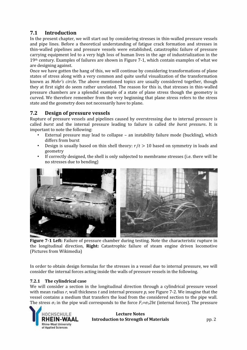
7.1 Introduction In the present chapter, we will start out by considering stresses in thin-walled pressure vessels and pipe lines. Before a theoretical understanding of fatigue crack formation and stresses in thin-walled pipelines and pressure vessels were established, catastrophic failure of pressure carrying equipment led to a very high loss of human lives in the age of industrialization in the 19th century. Examples of failures are shown in Figure 7-1, which contain examples of what we are designing against. Once we have gotten the hang of this, we will continue by considering transformations of plane states of stress along with a very common and quite useful visualization of the transformation known as Mohr’s circle. The above mentioned topics are usually considered together, though they at first sight do seem rather unrelated. The reason for this is, that stresses in thin-walled pressure chambers are a splendid example of a state of plane stress though the geometry is curved. We therefore remember from the very beginning that plane stress refers to the stress state and the geometry does not necessarily have to plane.
7.2 Design of pressure vessels Rupture of pressure vessels and pipelines caused by overstressing due to internal pressure is called burst and the internal pressure leading to failure is called the burst pressure. It is important to note the following:
• External pressure may lead to collapse – an instability failure mode (buckling), which differs from burst
• Design is usually based on thin shell theory: 𝑟/𝑡 > 10 based on symmetry in loads and geometry
• If correctly designed, the shell is only subjected to membrame stresses (i.e. there will be no stresses due to bending)
Figure 7-1 Left: Failure of pressure chamber during testing. Note the characteristic rupture in the longitudinal direction, Right: Catastrophic failure of steam engine driven locomotive (Pictures from Wikimedia)
In order to obtain design formulas for the stresses in a vessel due to internal pressure, we will consider the internal forces acting inside the walls of pressure vessels in the following.
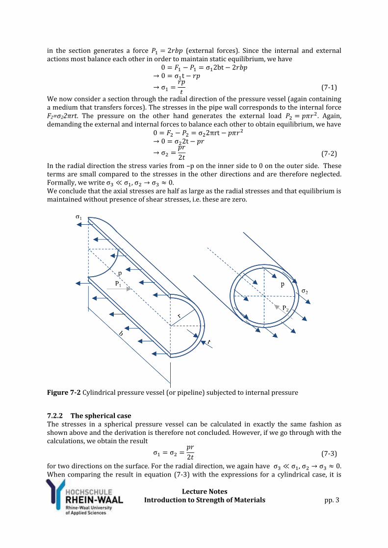
7.2.1 The cylindrical case We will consider a section in the longitudinal direction through a cylindrical pressure vessel with mean radius r, wall thickness t and internal pressure p, see Figure 7-2. We imagine that the vessel contains a medium that transfers the load from the considered section to the pipe wall. The stress σ1 in the pipe wall corresponds to the force F1=σ12bt (internal forces). The pressure
Lecture Notes
Introduction to Strength of Materials
pp. 3
in the section generates a force 𝑃1 = 2𝑟𝑏𝑝 (external forces). Since the internal and external actions most balance each other in order to maintain static equilibrium, we have 0 = 𝐹1 − 𝑃1 = σ12bt − 2𝑟𝑏𝑝
→ 0 = σ1t − 𝑟𝑝
→ σ1 =𝑟𝑝
𝑡
(7-1)
We now consider a section through the radial direction of the pressure vessel (again containing a medium that transfers forces). The stresses in the pipe wall corresponds to the internal force F2=σ22πrt. The pressure on the other hand generates the external load 𝑃2 = 𝑝𝜋𝑟2. Again, demanding the external and internal forces to balance each other to obtain equilibrium, we have 0 = 𝐹2 − 𝑃2 = σ22πrt − 𝑝𝜋𝑟2
→ 0 = σ22t − 𝑝𝑟
→ σ2 =𝑝𝑟
2𝑡
(7-2)
In the radial direction the stress varies from –p on the inner side to 0 on the outer side. These terms are small compared to the stresses in the other directions and are therefore neglected. Formally, we write σ3 ≪ σ1, σ2 → σ3 ≈ 0. We conclude that the axial stresses are half as large as the radial stresses and that equilibrium is maintained without presence of shear stresses, i.e. these are zero.
Figure 7-2 Cylindrical pressure vessel (or pipeline) subjected to internal pressure
7.2.2 The spherical case The stresses in a spherical pressure vessel can be calculated in exactly the same fashion as shown above and the derivation is therefore not concluded. However, if we go through with the calculations, we obtain the result σ1 = σ2 =
𝑝𝑟
2𝑡 (7-3)
for two directions on the surface. For the radial direction, we again have σ3 ≪ σ1, σ2 → σ3 ≈ 0. When comparing the result in equation (7-3) with the expressions for a cylindrical case, it is
Lecture Notes
Introduction to Strength of Materials
pp. 4
clear that the stress level is lower in a spherical geometry. Cylindrical pressure vessels are actually sub-optimal from a strict structural mechanics perspective. However, since cylindrical shapes are easier to handle, fit into a plant and often more suited for transport, these are widely applied due to simple practical considerations.
7.2.3 Practical considerations When designing pressure carrying equipment, it is of great importance to remember, that a number of factors govern the design which not only can be based on stress calculations using the formulas above. Some of the factors to remember are:
Pressure carrying equipment should contain pressure relief valves (PSV) preventing the pressure in the system to cause burst
When a tank is emptied, a vacuum may appear inside the tank. This has an effect similar to an external pressure and may collapse the tank. In many cases, this can be resolved by adding a valve at the top of a tank, which not only functions as PSV, but also opens if the pressure drops below atmospheric level so the tank is filled with air. This does not only apply for fluids, but also for systems storing solid particles.
An appropriate design stress criteria, usally von Mises, must be applied to the stresses σ1 and σ2 to obtain a reference stress for design.
End caps and man-holes induce stress concentrations and must be calculated separately. These are not accounted for in the present framework. Especially the transition from a cylindrical sweep to a spherical end cap requires attention and is often designed using FEA.
Most pressure carrying equipment is tested with 1.5 times the design pressure prior to service to ensure the integrity of the design.
The collapse pressure of a cylindrical pressure vessel or pipeline subjected to external pressure is given by (result from thin shell theory solved as bifurcation buckling problem): 𝑝𝐸 =
2𝐸
1−𝜈2
1
(𝐷
𝑡−1)
2 (7-4)
This formula does not account for ovalization due to manufacturing faults or bending. These effects might reduce the collapse pressure severely and requires further analysis.
7.3 Transformation of plane stress
7.3.1 Principal stresses We recall from chapter 1, that the stresses on the oblique section depend on the angle of the section. An axially loaded bar will now be considered. The stresses on the oblique section vary harmonically as functions of the angle, see Figure 7-3. We derived the expressions
𝜎 =𝐹
𝐴0𝑐𝑜𝑠2𝜃 𝜏 =
𝐹
𝐴0𝑐𝑜𝑠𝜃 𝑠𝑖𝑛𝜃
A direction for which the shear stresses vanish and leave us with a state of pure normal stress is called a principal direction. The corresponding normal stresses are called principal stresses. In the present example the first principal direction is the axial direction in which the load is applied and the corresponding principal stress is F/A0. The second principal direction perpendicular to the first direction and the corresponding principal stress is 0 (minimum normal stress value). We observed that the shear stress is 0 in both principal directions. A transformation to principal coordinates gives us maximum normal stresses and no shear.

Lecture Notes
Introduction to Strength of Materials
pp. 5
Figure 7-3 Left: Stresses on the oblique section of an axially loaded bar, Right: Normal and shear stresses as function of the oblique angle A state of stress is said to be plane if it can be described in terms of two normal components, 𝜎𝑥 and 𝜎𝑦 along with a shear component 𝜏𝑥𝑦 (I.e. the remaining stress components must be zero –
or sufficiently small to be neglected). A thin-walled pipeline subjected to internal pressure with stresses
σ1 =𝑟𝑝
𝑡 σ2 =
𝑝𝑟
2𝑡
is also in a state of plane stress. We note that the shear stress is zero, i.e. this is a principal state of stress and the axial and hoop directions are principal directions. If different sections were chosen, shear stress components would emerge. We may say, that the stress state has been transformed by rotation if a different section is chosen.
Figure 7-4 Left: stress components on a small segment of material in plane stress, Right: Principal directions in a cylindrical pressure vessel
7.3.2 The transformation equations A set of equations relating two states of plane stress in two different coordinate systems will
now be derived. If the stress equilibrium of a small oblique section of an elastic body in plane
stress is considered, the stress states in the two coordinate systems xyz and x’y’z’ (with z=z’) are
to be related, see Figure 7-5. Since a stress state has three components (two normal and one
shear stress component), this is slightly more complicated than conventional plane
transformations.

Lecture Notes
Introduction to Strength of Materials
pp. 6
Figure 7-5 Two states of plane stress related by the stress transformation equations The system x’y’z’ is obtained by rotating xyz counter clockwise. If we sum up the stress projections of the stress components in the xy system and project them onto the x’y’ axes, we obtain the three equations
𝜎𝑥′ =𝜎𝑥 + 𝜎𝑦
2+
𝜎𝑥 − 𝜎𝑦
2𝑐𝑜𝑠(2𝜃) + 𝜏𝑥𝑦𝑠𝑖𝑛(2𝜃) (7-5)
𝜎𝑦′ =
𝜎𝑥 + 𝜎𝑦
2−
𝜎𝑥 − 𝜎𝑦
2𝑐𝑜𝑠(2𝜃) − 𝜏𝑥𝑦𝑠𝑖𝑛(2𝜃) (7-6)
𝜏𝑥′𝑦′ = −𝜎𝑥 − 𝜎𝑦
2𝑠𝑖𝑛(2𝜃) + 𝜏𝑥𝑦𝑐𝑜𝑠(2𝜃) (7-7)
These can be applied to transform a state of plane stress from one section to another. We will now on basis of the stress transformation equations derive a practical visualization known as Mohr’s circle for plane stress. Before proceeding, it is noted that if a small element is rotated with an angle of θ, the angle applied in the transformation equations is 2θ. This will also apply when rotating stress states using Mohr’s circle.
7.3.3 Mohr’s circle Rearranging and squaring the expression for 𝜎𝑥′ we obtain
𝜎𝑥′ =𝜎𝑥+𝜎𝑦
2+
𝜎𝑥−𝜎𝑦
2𝑐𝑜𝑠(2𝜃) + 𝜏𝑥𝑦𝑠𝑖𝑛(2𝜃)
→ (𝜎𝑥′ −𝜎𝑥+𝜎𝑦
2)
2= (
𝜎𝑥−𝜎𝑦
2𝑐𝑜𝑠(2𝜃) + 𝜏𝑥𝑦𝑠𝑖𝑛(2𝜃))
2
(7-8)
Squaring the expression for 𝜏𝑥′𝑦′ we get
𝜏𝑥′𝑦′ = −𝜎𝑥−𝜎𝑦
2𝑠𝑖𝑛(2𝜃) + 𝜏𝑥𝑦𝑐𝑜𝑠(2𝜃)
→ (𝜏𝑥′𝑦′)2
= (−𝜎𝑥−𝜎𝑦
2𝑠𝑖𝑛(2𝜃) + 𝜏𝑥𝑦𝑐𝑜𝑠(2𝜃))
2
(7-9)
Adding equations (I) and (II) we obtain
(𝜎𝑥′ −𝜎𝑥 + 𝜎𝑦
2)
2
+ (𝜏𝑥′𝑦′)2
= (𝜎𝑥 − 𝜎𝑦
2𝑐𝑜𝑠(2𝜃) + 𝜏𝑥𝑦𝑠𝑖𝑛(2𝜃))
2
+ (−𝜎𝑥 − 𝜎𝑦
2𝑠𝑖𝑛(2𝜃) + 𝜏𝑥𝑦𝑐𝑜𝑠(2𝜃))
2
→ (𝜎𝑥′ −𝜎𝑥 + 𝜎𝑦
2)
2
+ (𝜏𝑥′𝑦′)2
= (𝜎𝑥 − 𝜎𝑦
2)
2
+ (𝜏𝑥𝑦)2
(7-10)

Lecture Notes
Introduction to Strength of Materials
pp. 7
This is recognized as the equation of a circle with radius 𝑅 = √ (𝜎𝑥−𝜎𝑦
2)
2+ (𝜏𝑥𝑦)
2 and center
(𝜎𝑚, 0) = (𝜎𝑥+𝜎𝑦
2, 0). We call this Mohr’s circle named after the German engineer Christian Otto
Mohr. For a shear stress oriented as shown (τ>0) we draw the circle by the following steps
1. Calculate R and 𝜎𝑚 2. Plot (𝜎𝑚, 0) along with the two points (𝜎𝑥, −𝜏𝑥𝑦) and (𝜎𝑦, 𝜏𝑥𝑦)
3. Draw the circle as shown below in Figure 7-6
Figure 7-6 Drawing Mohr’s circle I For a shear stress oriented as shown (τ<0), the points on the circumference will be located in a slightly differently, see Figure 7-7.
Figure 7-7 Drawing Mohr’s circle II

Lecture Notes
Introduction to Strength of Materials
pp. 8
By drawing Mohr’s circle, we can: • Determine the principal stresses 𝜎𝑚𝑎𝑥 and 𝜎𝑚𝑖𝑛 (also called 𝜎1 and 𝜎2) as intersections
with x-axis and the corresponding rotation required to obtain those (the angle 𝜃) • Determine the maximum shear stress 𝜏𝑚𝑎𝑥 found for a rotation of 45 deg. from the
principal stresses • Carry out transformation of plane stress states graphically
That is eventually rather handy. As examples, we may construct Mohr’s circle for a few common stress states we have considered earlier in the course.
A.
B.
C.
Figure 7-8 Mohr’s circle for A. a thin-walled pressure vessel subjected to internal pressure, B. an oblique section in an axially loaded bar, C. A shaft in pure torsion
Lecture Notes
Introduction to Strength of Materials
pp. 9
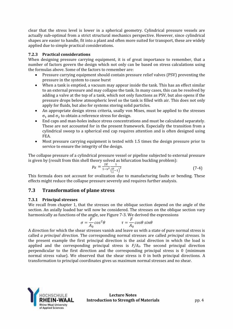
Calculated example 7A: Transformation of plane stress For the plane stress segment shown, the stress components are given by σx=40 N/mm2, σy=-30 N/mm2 and τxy=20 N/mm2. Calculate a) the principal stresses, b) the corresponding angle of rotation, c) Furthermore, draw Mohr’s circle for the stress state shown, d) calculate the maximum shear stress and the corresponding angle of rotation.
Figure 7-9
Solution: a) The principal stresses are calculated by
𝜎𝑎𝑣 =𝜎1+𝜎2
2=
40−30
2
𝑁
𝑚𝑚2
𝑅 = √ (𝜎𝑥−𝜎𝑦
2)
2+ (𝜏𝑥𝑦)
2=√ (
40−(−30)
2)
2+ (20)2 𝑁
𝑚𝑚2 = 40.3𝑁
𝑚𝑚2
𝜎1 = 𝜎𝑎𝑣 + 𝑅 = 45.3𝑁
𝑚𝑚2 𝜎2 = 𝜎𝑎𝑣 − 𝑅 = −35.3𝑁
𝑚𝑚2
b) The angle of rotation required to obtained the principal coordinates is given by
tan(2𝜃) =2𝜏𝑥𝑦
𝜎𝑥−𝜎𝑦=
2∙20
40−(−30)→ 𝜃1 = 14.87 deg (counter-clockwise)
c) Mohr’s circle can now be drawn
Figure 7-10 d) The maximum shear stress is given by
𝜏𝑚𝑎𝑥 = 𝑅 = 40.3𝑁
𝑚𝑚2
For a counter-clockwise rotation in Mohr’s circle of 2𝜃1 + 90deg corresponding to a segment rotation of 𝜃1 + 45deg = 59.87deg.
Lecture Notes
Introduction to Strength of Materials
pp. 10
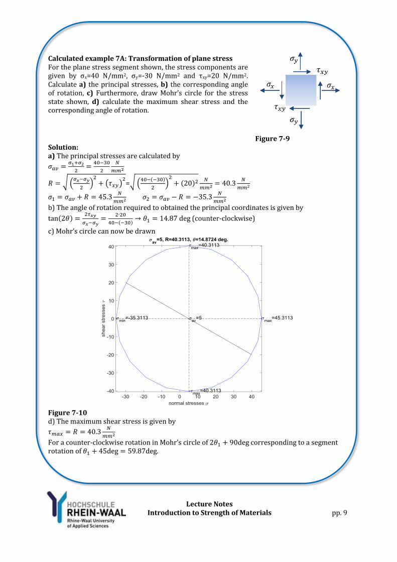
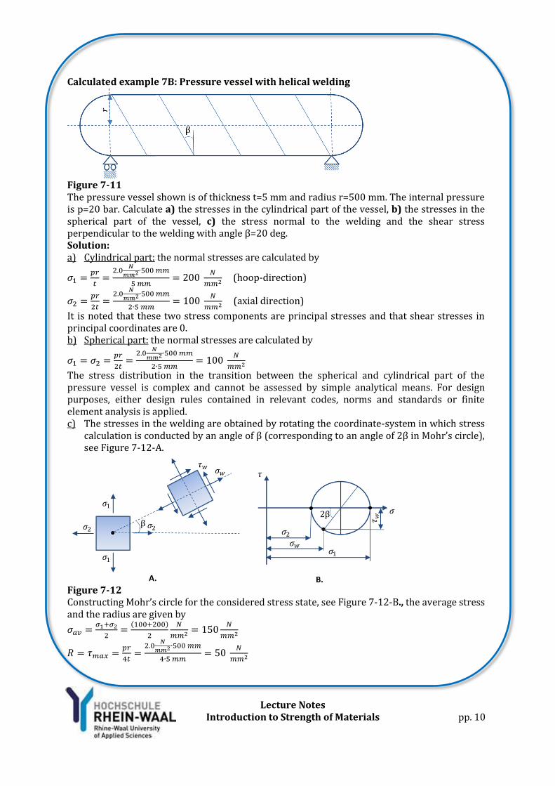
Calculated example 7B: Pressure vessel with helical welding
Figure 7-11 The pressure vessel shown is of thickness t=5 mm and radius r=500 mm. The internal pressure is p=20 bar. Calculate a) the stresses in the cylindrical part of the vessel, b) the stresses in the spherical part of the vessel, c) the stress normal to the welding and the shear stress perpendicular to the welding with angle β=20 deg. Solution: a) Cylindrical part: the normal stresses are calculated by
𝜎1 =𝑝𝑟
𝑡=
2.0𝑁
𝑚𝑚2∙500 𝑚𝑚
5 𝑚𝑚= 200
𝑁
𝑚𝑚2 (hoop-direction)
𝜎2 =𝑝𝑟
2𝑡=
2.0𝑁
𝑚𝑚2∙500 𝑚𝑚
2∙5 𝑚𝑚= 100
𝑁
𝑚𝑚2 (axial direction)
It is noted that these two stress components are principal stresses and that shear stresses in principal coordinates are 0. b) Spherical part: the normal stresses are calculated by
𝜎1 = 𝜎2 =𝑝𝑟
2𝑡=
2.0𝑁
𝑚𝑚2∙500 𝑚𝑚
2∙5 𝑚𝑚= 100
𝑁
𝑚𝑚2
The stress distribution in the transition between the spherical and cylindrical part of the pressure vessel is complex and cannot be assessed by simple analytical means. For design purposes, either design rules contained in relevant codes, norms and standards or finite element analysis is applied. c) The stresses in the welding are obtained by rotating the coordinate-system in which stress
calculation is conducted by an angle of β (corresponding to an angle of 2β in Mohr’s circle), see Figure 7-12-A.
Figure 7-12 Constructing Mohr’s circle for the considered stress state, see Figure 7-12-B., the average stress and the radius are given by
𝜎𝑎𝑣 =𝜎1+𝜎2
2=
(100+200)
2
𝑁
𝑚𝑚2 = 150𝑁
𝑚𝑚2
𝑅 = 𝜏𝑚𝑎𝑥 =𝑝𝑟
4𝑡=
2.0𝑁
𝑚𝑚2∙500 𝑚𝑚
4∙5 𝑚𝑚= 50
𝑁
𝑚𝑚2

Lecture Notes
Introduction to Strength of Materials
pp. 11
[Example 7B continued …] The desired stress components are now obtained by on basis of the relations for right angle triangles and are calculated by
𝜎𝑤 = 𝜎𝑎𝑣 − 𝑅cos(2𝛽) = (150 − 50cos(2 ∙ 20))𝑁
𝑚𝑚2 = 111.7𝑁
𝑚𝑚2
𝜏𝑤 = 𝑅sin(2𝛽) = 50 ∙ sin(2 ∙ 20)𝑁
𝑚𝑚2 = 32.1𝑁
𝑚𝑚2

Lecture Notes
Introduction to Strength of Materials
pp. 12
Calculated example 7C: stresses in a beam section
Figure 7-13 The cantilever beam shown in Figure 7-13, the length is given by L=5 m, the load by P=50 kN and the moment of inertia Iz=3.67∙108 mm4 based on cross-sectional parameters h=325 mm, b=310 mm, tf=40 mm and tw=20 mm. Calculate a) the maximum normal stress due to bending, b) the maximum shear stress in the cross-section, c) the principal stress in the flange-web junction, d) the von Mises Stress in the flange-web junction Solution a) The applied load can be observed to cause a negative internal bending moment in the beam, so Mmax=-PL. On basis of the flexure formula, we realize that the maximum tensile normal stress due to bending will occur for y=h/2 at the upper face of the beam (since Mz<0). Hence, we obtain
𝜎𝑥,𝑚𝑎𝑥 = −𝑀𝑧
ℎ
2
𝐼𝑧= −
−50∙103N∙5000mm∙325mm
2
3.67∙108mm4 = 110.7 N/mm2
It is noted, that for the upper face 𝜏𝑢𝑝𝑝𝑒𝑟 𝑓𝑎𝑐𝑒 = 0.
b) The maximum shear force in the beam is given by Vmax=P and will occur for y=0 along the neutral plane. For the area above the neutral axis, the first order area moment is calculated
by𝑄 = 𝑄𝑤𝑒𝑏 + 𝑄𝑓𝑙𝑎𝑛𝑔𝑒 = ((ℎ
2− 𝑡𝑓) 𝑡𝑤)
(ℎ
2−𝑡𝑓)
2+ (𝑏𝑡𝑓) (
ℎ
2−
𝑡𝑓
2) = 1.257 ∙ 106mm3
The shear stress can now be calculated by Grasshofs Formula
𝜏 =𝑉𝑄
𝐼𝑧𝑡𝑤=
50∙103N∙1.257∙106mm3
3.67∙108mm4∙15 mm= 17.13 N/mm2
c) The bending stress in the flange-web junction can be obtained by scaling the maximum stress by
𝜎𝑥,𝑗𝑢𝑛𝑐 = 𝜎𝑥,𝑚𝑎𝑥
ℎ2 − 𝑡𝑓
ℎ2
= 93.69 N/mm2
The first order area moment of the section considered can be found directly from the calculation in b) and equals the term 𝑄𝑓𝑙𝑎𝑛𝑔𝑒 = 1.163 ∙ 106mm3. The shear stress in the
junction is now given by
𝜏𝑗𝑢𝑛𝑐 =50∙103N∙1.917∙106mm3
3.67∙108mm4∙15 mm= 15.84 N/mm2
The maximum principal stress is now (for σy=0) given by
𝜎𝑚𝑎𝑥 = 𝜎𝑎𝑣 + 𝑅 =𝜎𝑥,𝑗𝑢𝑛𝑐
2+ √(
𝜎𝑥,𝑗𝑢𝑛𝑐
2)
2+ 𝜏𝑗𝑢𝑛𝑐
2 = 96.3 N/mm2
d) The von Mises stress is (for σy=0) given by
𝜎𝑟𝑒𝑓 = √𝜎𝑥,𝑗𝑢𝑛𝑐2 + 3𝜏𝑗𝑢𝑛𝑐
2 = 97.6 N/mm2

Lecture Notes
Introduction to Strength of Materials
pp. 13
Problems
Figure 7.1a- Figure 7.2a Figure 7.1b- Figure 7.2b Problem 7.1 The two pressure vessels shown in Figure 7.1 has thickness t=5 mm and radius r=100 mm. The internal pressure is specified to p=25 bar. Assuming the state of stress plane, a) Calculate the stresses in the directions r1 and r2, b) Calculate the maximum in-plane shear stress in the wall of the pressure vessel, c) Calculate the principal stresses, d) Construct Mohr’s circle for the stress state. Assumining the stress state three dimensional, e) calculate the maximum out-of-plane stress in the pressure vessel Ans: Cylindrical case: a) σ1=50 N/mm2, σ1=25 N/mm2, b) τmax-in-plane=12.5 N/mm2, c) -, d) τmax-out-of-plane=25 N/mm2, e) – Spherical case: a) σ1=25 N/mm2, σ1=25 N/mm2, b) τmax-in-plane=0, c) -, d) τmax-out-of-plane=12.5 N/mm2, e) - Problem 7.2 Considering the pressure vessels shown in Figure 7.2 with geometry given in problem 7.1, calculate the maximum internal pressure that can be allowed, if the nominal normal stress is not to exceed 150 N/mm2 in each of the principal directions. Ans: Cylindrical case: stress in direction 1: pallow=7.5 N/mm2, stress in direction 2: pallow=15 N/mm2 Spherical case: stress in direction 1 and 2: pallow=15 N/mm2
Figure 7.3-Figure 7.4 Problem 7.3 The pressure vessel shown in figure 7.3 is of radius r=200 mm and thickness t=5 mm. The helical angle of the shown welding is β=25 deg. For a maximum allowable normal stress perpendicular to the welding 𝜎𝑤,𝑎𝑙𝑙𝑜𝑤 =100 N/mm2, determine the maximum nominal internal
pressure the vessel can sustain Ans: p<4.24 N/mm2

Lecture Notes
Introduction to Strength of Materials
pp. 14
Problem 7.4 The pressure vessel shown in figure 7.3 is of radius r=200 mm and thickness t=5 mm. The helical angle of the shown welding is β=25 deg. For a maximum allowable shear stress 𝜏𝑤,𝑎𝑙𝑙𝑜𝑤
=25 N/mm2, determine the maximum nominal internal pressure the vessel can sustain Ans: p<3.26 N/mm2
Figure 7.5 Figure 7.6 Problem 7.5 For the plane stress segment shown above, the stress components are given by σx=50 N/mm2, σy=60 N/mm2 and τxy=30 N/mm2. Calculate a) the principal stresses, b) the corresponding angle of rotation, d) Furthermore, draw Mohr’s circle for the stress state shown, c) calculate the maximum shear stress. Ans: a) σ1=85.40 N/mm2, σ2=24. 59 N/mm2, b) θ1=40.27 deg, τmax=30.41 N/mm2 Problem 7.6 For the two stress states shown in Figure 7.6, the stress components are given by 𝜎𝑥,𝐴 =
0, 𝜎𝑦,𝐴 = 0, 𝜏𝑥𝑦,𝐴 = 95 N/mm2 with β=45 deg. and 𝜎𝑥,𝐵 = 44 N/mm2, 𝜎𝑦,𝐵 = 88 N/
mm2 , 𝜏𝑥𝑦,𝐵 = 35 N/mm2. a) Determine the resultant stress state obtained by superposition of
A and B, b) For the resultant stress state, determine the principal stresses and the angle of rotation required to obtain the principal axes. Ans: a) 𝜎𝑥 = 139 N/mm2, 𝜎𝑦 = −7 N/mm2, 𝜏𝑥𝑦 = 35 N/mm2
b) 𝜎1 = 146.96 N/mm2, 𝜎2 = −14.96 N/mm2, 𝜃1 = 12.8 deg , 𝜃1 = 102.8 deg