Embed Size (px)
Citation preview

8/10/2019 7 Capture Compare PWM
http://slidepdf.com/reader/full/7-capture-compare-pwm 1/19
M i c r o c
o n t r o l l e r s
CAPTURE/COMPARE/PWMMODULES
1
8/10/2019 7 Capture Compare PWM
http://slidepdf.com/reader/full/7-capture-compare-pwm 2/19
M i c r o c
o n t r o l l e r s
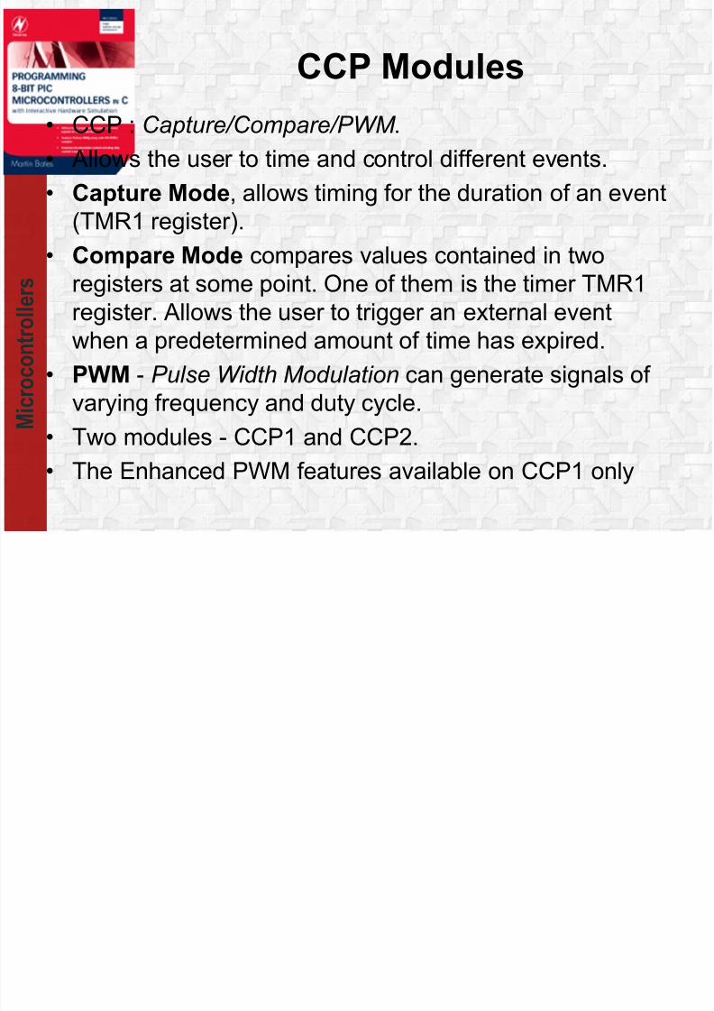
CCP Modules
• CCP : Capture/Compare/PWM .• Allows the user to time and control different events.
• Capture Mode, allows timing for the duration of an event
(TMR1 register).
• Compare Mode compares values contained in tworegisters at some point. One of them is the timer TMR1
register. Allows the user to trigger an external event
when a predetermined amount of time has expired.
• PWM - Pulse Width Modulation can generate signals ofvarying frequency and duty cycle.
• Two modules - CCP1 and CCP2.
• The Enhanced PWM features available on CCP1 only
8/10/2019 7 Capture Compare PWM
http://slidepdf.com/reader/full/7-capture-compare-pwm 3/19
M i c r o c
o n t r o l l e r s
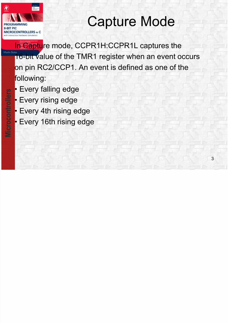
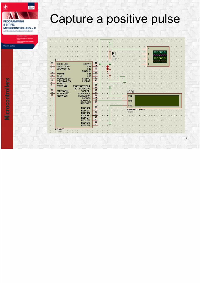
Capture Mode
In Capture mode, CCPR1H:CCPR1L captures the
16-bit value of the TMR1 register when an event occurs
on pin RC2/CCP1. An event is defined as one of the
following:• Every falling edge
• Every rising edge
• Every 4th rising edge
• Every 16th rising edge
3

8/10/2019 7 Capture Compare PWM
http://slidepdf.com/reader/full/7-capture-compare-pwm 4/19
8/10/2019 7 Capture Compare PWM
http://slidepdf.com/reader/full/7-capture-compare-pwm 5/19
M i c r o c
o n t r o l l e r s
Capture a positive pulse
5
8/10/2019 7 Capture Compare PWM
http://slidepdf.com/reader/full/7-capture-compare-pwm 6/19
M i c r o c
o n t r o l l e r s
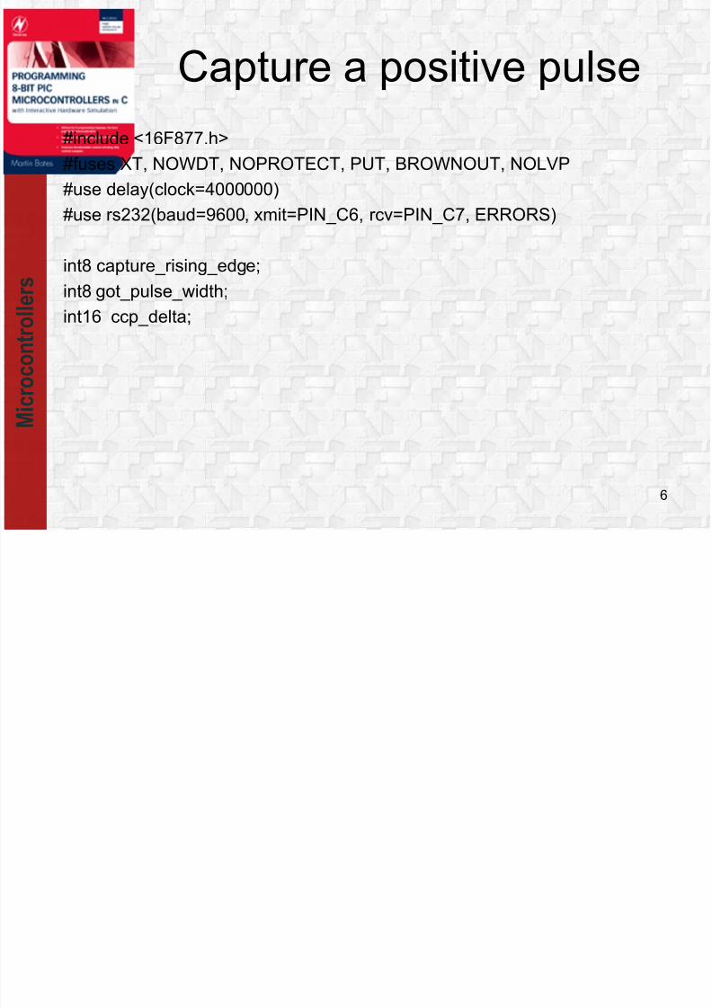
#include <16F877.h>
#fuses XT, NOWDT, NOPROTECT, PUT, BROWNOUT, NOLVP
#use delay(clock=4000000)
#use rs232(baud=9600, xmit=PIN_C6, rcv=PIN_C7, ERRORS)
int8 capture_rising_edge;
int8 got_pulse_width;
int16 ccp_delta;
6
Capture a positive pulse

8/10/2019 7 Capture Compare PWM
http://slidepdf.com/reader/full/7-capture-compare-pwm 7/19
M i c r o c
o n t r o l l e r s
#int_ccp1
void ccp1_isr(void) {
static int16 t1_rising_edge;
// If current interrupt is for rising edge.
if(capture_rising_edge) {setup_ccp1(CCP_CAPTURE_FE); capture_rising_edge = FALSE;
t1_rising_edge = CCP_1;
}
else {
setup_ccp1(CCP_CAPTURE_RE); capture_rising_edge = TRUE;ccp_delta = CCP_1 - t1_rising_edge; got_pulse_width = TRUE;
}
}
7
Capture a positive pulse

8/10/2019 7 Capture Compare PWM
http://slidepdf.com/reader/full/7-capture-compare-pwm 8/19
M i c r o c
o n t r o l l e r s
main() {
int16 pulse_width_ms; int16 local_ccp_delta;
got_pulse_width = FALSE; capture_rising_edge = TRUE;
setup_ccp1(CCP_CAPTURE_RE);
setup_timer_1(T1_INTERNAL | T1_DIV_BY_8 );enable_interrupts(INT_CCP1); enable_interrupts(GLOBAL);
while(1) {
if(got_pulse_width) {
disable_interrupts(GLOBAL); local_ccp_delta = ccp_delta;
enable_interrupts(GLOBAL); pulse_width_ms = local_ccp_delta / 125;putc(254); putc(1); delay_ms(10);
printf("%lu ms \n\r", pulse_width_ms); got_pulse_width = FALSE;
}
}
} 8
Capture a positive pulse

8/10/2019 7 Capture Compare PWM
http://slidepdf.com/reader/full/7-capture-compare-pwm 9/19
M i c r o c
o n t r o l l e r s
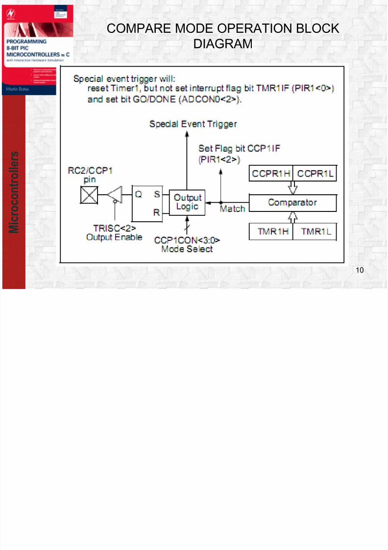
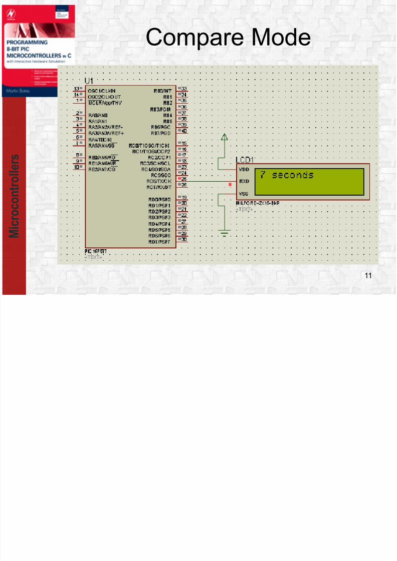
Compare Mode
In Compare mode, the 16-bit CCPR1 register value is
constantly compared against the TMR1 register pair
value. When a match occurs, the RC2/CCP1 pin is:
• Driven high
• Driven low
• Remains unchanged
9
8/10/2019 7 Capture Compare PWM
http://slidepdf.com/reader/full/7-capture-compare-pwm 10/19
M i c r o c
o n t r o l l e r s
COMPARE MODE OPERATION BLOCK
DIAGRAM
10
8/10/2019 7 Capture Compare PWM
http://slidepdf.com/reader/full/7-capture-compare-pwm 11/19
M i c r o c
o n t r o l l e r s
11
Compare Mode

8/10/2019 7 Capture Compare PWM
http://slidepdf.com/reader/full/7-capture-compare-pwm 12/19
M i c r o c
o n t r o l l e r s
12
#include<16f877a.h>
#fuses XT,NOLVP,NOWDT,PUT
#use delay(clock=4000000)
#use rs232(baud=9600,xmit=PIN_C6,rcv=PIN_C7)
#define high_start 2 //25
unsigned int8 seconds, high_count;
#INT_CCP1 //Interrupt procedure
clock_isr() {
high_count -= 1;
if(high_count==0) {
++seconds; if (seconds==60) seconds=0;
high_count=high_start;
putc(254); putc(1); delay_ms(10);
printf("%u seconds \n\r", seconds);
}}
Compare Mode

8/10/2019 7 Capture Compare PWM
http://slidepdf.com/reader/full/7-capture-compare-pwm 13/19
M i c r o c
o n t r o l l e r s
13
void main() {
delay_ms(500); putc(254); putc(1); delay_ms(10);
seconds=0;
printf("%u seconds \n\r", seconds);
high_count = high_start;
setup_ccp1 (CCP_COMPARE_INT);
setup_timer_1(T1_INTERNAL | T1_DIV_BY_8 );
set_timer1(0);
CCP_1=5000;
enable_interrupts(INT_CCP1);
enable_interrupts(GLOBAL);
while(TRUE) {} ;
}
Compare Mode

8/10/2019 7 Capture Compare PWM
http://slidepdf.com/reader/full/7-capture-compare-pwm 14/19
M i c r o c
o n t r o l l e r s
Pulse Width Modulation
PWM Mode
14
In Pulse Width
Modulation mode, the
CCPx pin produces up
to a 10-bit resolution
PWM output

8/10/2019 7 Capture Compare PWM
http://slidepdf.com/reader/full/7-capture-compare-pwm 15/19

8/10/2019 7 Capture Compare PWM
http://slidepdf.com/reader/full/7-capture-compare-pwm 16/19
M i c r o c
o n t r o l l e r s
PWM output
#include "16F877A.h"
void main()
{setup_ccp1(ccp_pwm);
setup_timer_2(T2_DIV_BY_16,250,1);
set_pwm1_duty(500);
while(1){}
}
16
duty cycle = value / [ 4 * (PR2 +1 ) ]

8/10/2019 7 Capture Compare PWM
http://slidepdf.com/reader/full/7-capture-compare-pwm 17/19
M i c r o c
o n t r o l l e r s
17

8/10/2019 7 Capture Compare PWM
http://slidepdf.com/reader/full/7-capture-compare-pwm 18/19
M i c r o c
o n t r o l l e r s
Demo PWM output
#include "16F877A.h"#fuses XT,NOLVP,NOWDT,PUT
#use delay(clock=4000000)
unsigned int8 current_duty, old_duty;
void main() {
current_duty = 128; old_duty = 0;
setup_ccp1(ccp_pwm); setup_timer_2(T2_DIV_BY_16,250,1);
set_pwm1_duty(current_duty);
while (1) {
if (!input(PIN_A0)) current_duty +=5;
if (!input(PIN_A1)) current_duty-=5 ;
if (old_duty != current_duty) {set_pwm1_duty(current_duty);
old_duty = current_duty; OUTPUT_B(old_duty);
}
Delay_ms(200);
}
} 18

8/10/2019 7 Capture Compare PWM
http://slidepdf.com/reader/full/7-capture-compare-pwm 19/19
M i c r o c
o n t r o l l e r s
19
Demo PWM output

![Index [booksite.elsevier.com] · Capture/Compare/PWM, 275 capture mode, 275 Carry flag, 32, 36, 102 CCP - see Capture/Compare/PWM Central Processing Unit, 7, 16 character set, 12,](https://img.pdfslide.us/doc/110x75/5e033c75d9e2ea2f2042647e/index-capturecomparepwm-275-capture-mode-275-carry-iag-32-36-102-ccp.jpg)


![Bidirectional Speed Control of DC Motor Based on Pulse ...ijsrst.com/paper/157.pdfGeneration of PWM using PIC16F877A The PIC16F877A has two Capture/Compare/PWM (CCP) Modules [4]. Each](https://img.pdfslide.us/doc/110x75/5ab16dc57f8b9ad9788c40d0/bidirectional-speed-control-of-dc-motor-based-on-pulse-of-pwm-using-pic16f877a.jpg)