Embed Size (px)
Citation preview
Ten Steps to Select a Diaphragm Seal
BULLETIN S10
Ashcroft Inc., 250 East Main Street, Stratford, CT 06614 USATel: 203-378-8281 • Fax: 203-385-0408email: [email protected] • www.ashcroft.com
All specifications are subject to change without notice. All sales subject to standard terms and conditions. © Ashcroft Inc. 2015 04/15
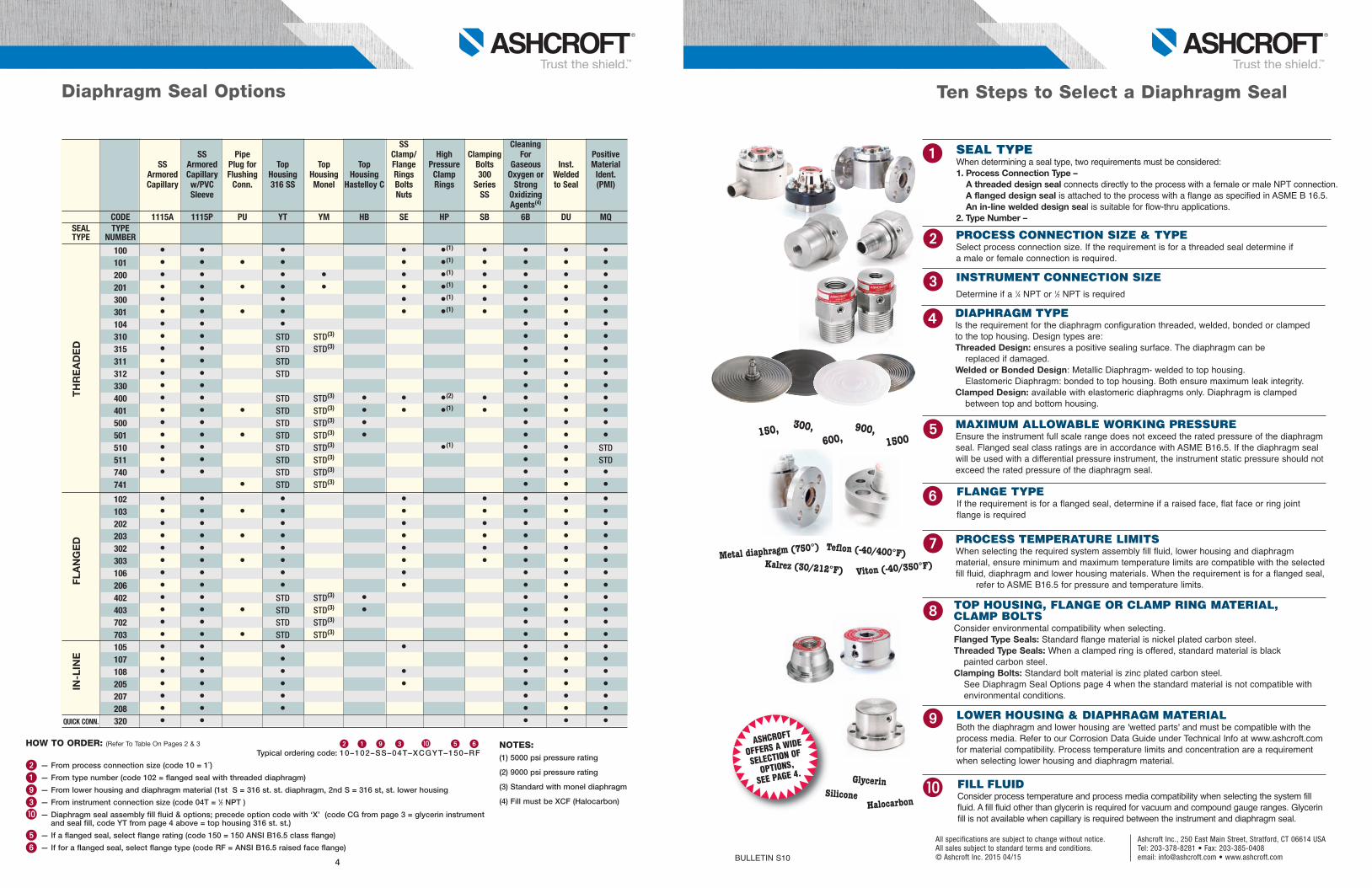
DIAPHRAGM TYPEIs the requirement for the diaphragm configuration threaded, welded, bonded or clamped to the top housing. Design types are:Threaded Design: ensures a positive sealing surface. The diaphragm can be replaced if damaged.
Welded or Bonded Design: Metallic Diaphragm- welded to top housing.Elastomeric Diaphragm: bonded to top housing. Both ensure maximum leak integrity.
Clamped Design: available with elastomeric diaphragms only. Diaphragm is clamped between top and bottom housing.
PROCESS TEMPERATURE LIMITS When selecting the required system assembly fill fluid, lower housing and diaphragm material, ensure minimum and maximum temperature limits are compatible with the selected fill fluid, diaphragm and lower housing materials. When the requirement is for a flanged seal, refer to ASME B16.5 for pressure and temperature limits.
TOP HOUSING, FLANGE OR CLAMP RING MATERIAL, CLAMP BOLTS Consider environmental compatibility when selecting. Flanged Type Seals: Standard flange material is nickel plated carbon steel. Threaded Type Seals: When a clamped ring is offered, standard material is black painted carbon steel. Clamping Bolts: Standard bolt material is zinc plated carbon steel. See Diaphragm Seal Options page 4 when the standard material is not compatible with environmental conditions.
LOWER HOUSING & DIAPHRAGM MATERIAL Both the diaphragm and lower housing are 'wetted parts' and must be compatible with the
process media. Refer to our Corrosion Data Guide under Technical Info at www.ashcroft.comfor material compatibility. Process temperature limits and concentration are a requirementwhen selecting lower housing and diaphragm material.
FILL FLUID Consider process temperature and process media compatibility when selecting the system fill fluid. A fill fluid other than glycerin is required for vacuum and compound gauge ranges. Glycerin fill is not available when capillary is required between the instrument and diaphragm seal.
INSTRUMENT CONNECTION SIZEDetermine if a 1⁄4 NPT or 1⁄2 NPT is required
SEAL TYPEWhen determining a seal type, two requirements must be considered: 1. Process Connection Type –A threaded design seal connects directly to the process with a female or male NPT connection. A flanged design seal is attached to the process with a flange as specified in ASME B 16.5. An in-line welded design seal is suitable for flow-thru applications.
2. Type Number –
PROCESS CONNECTION SIZE & TYPESelect process connection size. If the requirement is for a threaded seal determine if a male or female connection is required.
MAXIMUM ALLOWABLE WORKING PRESSUREEnsure the instrument full scale range does not exceed the rated pressure of the diaphragm seal. Flanged seal class ratings are in accordance with ASME B16.5. If the diaphragm seal will be used with a differential pressure instrument, the instrument static pressure should notexceed the rated pressure of the diaphragm seal.
FLANGE TYPEIf the requirement is for a flanged seal, determine if a raised face, flat face or ring joint flange is required
HOW TO ORDER: (Refer To Table On Pages 2 & 3 � � � � � Typical ordering code: 10–102–SS–04T–XCGYT–150–RF
� — From process connection size (code 10 = 1˝)
� — From type number (code 102 = flanged seal with threaded diaphragm)
— From lower housing and diaphragm material (1st S = 316 st. st. diaphragm, 2nd S = 316 st, st. lower housing
� — From instrument connection size (code 04T = 1⁄2 NPT )
— Diaphragm seal assembly fill fluid & options; precede option code with ‘X’ (code CG from page 3 = glycerin instrumentand seal fill, code YT from page 4 above = top housing 316 st. st.)
� — If a flanged seal, select flange rating (code 150 = 150 ANSI B16.5 class flange)
� — If for a flanged seal, select flange type (code RF = ANSI B16.5 raised face flange)
ASHCROFT
OFFERS A WIDE
SELECTION OF
OPTIONS,
SEE PAGE 4.
NOTES:(1) 5000 psi pressure rating
(2) 9000 psi pressure rating
(3) Standard with monel diaphragm
(4) Fill must be XCF (Halocarbon)
150, 300,600,
900, 1500
Metal diaphragm (750°) Teflon (-40/400°F)
Viton (-40/350°F)Kalrez (30/212°F)
Glycerin
HalocarbonSilicone
�
�
�
�
�
�
�
�
Diaphragm Seal Options
SS Cleaning SS Pipe Clamp/ High Clamping For Positive
SS Armored Plug for Top Top Top Flange Pressure Bolts Gaseous Inst. MaterialArmored Capillary Flushing Housing Housing Housing Rings Clamp 300 Oxygen or Welded Ident.Capillary w/PVC Conn. 316 SS Monel Hastelloy C Bolts Rings Series Strong to Seal (PMI)
Sleeve Nuts SS OxidizingAgents(4)
CODE 1115A 1115P PU YT YM HB SE HP SB 6B DU MQSEAL TYPETYPE NUMBER
100 • • • • •(1) • • • •101 • • • • • •(1) • • • •200 • • • • • •(1) • • • •201 • • • • • • •(1) • • • •300 • • • • •(1) • • • •301 • • • • • •(1) • • • •104 • • • • • •310 • • STD STD(3) • • •315 • • STD STD(3) • • •311 • • STD • • •312 • • STD • • •330 • • • • •400 • • STD STD(3) • • •(2) • • • •401 • • • STD STD(3) • • •(1) • • • •500 • • STD STD(3) • • • •501 • • • STD STD(3) • • • •510 • • STD STD(3) •(1) • • STD511 • • STD STD(3) • • STD740 • • STD STD(3) • • •741 • STD STD(3) • • •102 • • • • • • • •103 • • • • • • • • •202 • • • • • • • •203 • • • • • • • • •302 • • • • • • • •303 • • • • • • • • •106 • • • • • • •206 • • • • • • •402 • • STD STD(3) • • • •403 • • • STD STD(3) • • • •702 • • STD STD(3) • • •703 • • • STD STD(3) • • •105 • • • • • • •107 • • • • • •108 • • • • • • •205 • • • • • • •207 • • • • • •208 • • • • • •
QUICK CONN. 320 • • • • •
THREADED
FLANGED
IN-LINE
4
Ash Bul S-10 TTS.qxp_layout 4/1/15 10:36 AM Page 1
100 101
200 201
300 301
104 310
315 311
312 330
400 401
500 501
510 511
740 741
102 103
202 203
302 303
106 206
402 403
702 703
104 105
107 108
204 205
207 208
320
THREADED
FLANGED
IN-LINE
QUICKCONNECT
F/M F/M F/M F/M • • • • • • • • • • • • • • • •(5) • • • • • • • • • F/M F/M F/M F/M • • • • • • • • • • • • • •(5) • • • • • • • F/M F/M F/M F/M • • • • • • • • • • • • • • • • • • • • • •(5) • • • • • • • • • • • • • • F/M F/M F/M F/M • • • • • • • • • • • • • • • • • • •(5) • • • • • • • • • • • • F/M F/M F/M F/M • • • • • • • • • • • • • • • • •(4) •(4) •(4) •(4) •(4) •(4) •(4) •(4) •(4) • • • • • • • • F/M F/M F/M F/M • • • • • • • • • •(6) • • •(4) •(4) •(4) •(4) •(4) •(4) •(4) •(4) •(4) • • • • • • F F • • • • • • • • • • • • •(5) • • • • • F/M F/M M M • • • • • • • •(1) • • • F F • • • • • • • •(1) • • • F/M F/M F/M F/M • • • • • • • • • F F • • • • • • • • • ALL M • • • • • • • • F/M F/M F/M F/M • • • • • • • • •(1) •(2) • • • • • • F/M F/M F/M F/M • • • • • • • • •(1) •(2) • • • • • • F/M F/M F/M F/M • • • • • • • •(1) •(2) • • • • • • F/M F/M F/M F/M • • • • • • • •(1) •(2) • • • • • • M • • • • • • •(1) • • • • M • • • • • • •(1) • • • • F F F F • • • • • • • •(1) •(2) • • •(5) • • • • • F F F F • • • • • • • •(1) •(2) • • •(5) • • • • • • • • • • • • • • • • • • • • • • • • • • • •(6) • • • • • • • • • • • • • • • • • • • • • • • • • • • • • • • • • • • • • • • • • • • • • • •(5) • • • • • • • • • • • • • • • • • • • • • • • • • • • • • • • • • • • •(6) •(6) •(6) • • • • • • • • • • • • • •(4) • • • • • • • • • • • • • • • • • • • • • • • • • • • • • • • • • • • • •(5) • • • • • • • • • • • • • • • •(8) • • • • • • • • • • • • • • • • •(6) •(6) •(6) • • • •(4) •(4) •(4) •(4) •(4) •(4) •(4) •(4) •(4) • • • • • • • • • • • • • • • • • • • • • • • • • • • • • •(4) •(4) •(4) •(4) •(4) •(4) •(4) •(4) •(4) • • • • • • • • • • • • • • • • • • • • • • • • • • • • • • • •(5) •(5) • • • • •
ALL
• • • • • • • • • • • • • • • • • • • • • • • • • • • •(5) • • • • • • • • • • • • • • • • • • • • • • • • • • • • • •(1) • • • •(5) • • • • • • • • • • • • • • • • • • • • • • • • • •(1) • • • •(5) • • • • • • • • • • • • • • • • • • • • •(1) • • •(5) • • • • • • • • • • • • • • • • • • •(1) • • •(5) • • • • • • • • • • • • • • • • • • • • • • • • • • • • • • • • • • • • • • •(5) • • • • • • • • • • • • • • • • • • • • • • • • • •(5) • • • • • • • • • • • • • • • • • • • • • • • •(5) • • • • • • • • • • • • • • • • • • • • • • • • • • • • • • • • • • •(5) • • • • • ALL • • • • • • • • • • • • • • • • • • • • •(5) • • • • • • • • • • • • • • • • • • • • • • • • •(5) • • • • • • • • •(3) • • • • ALL
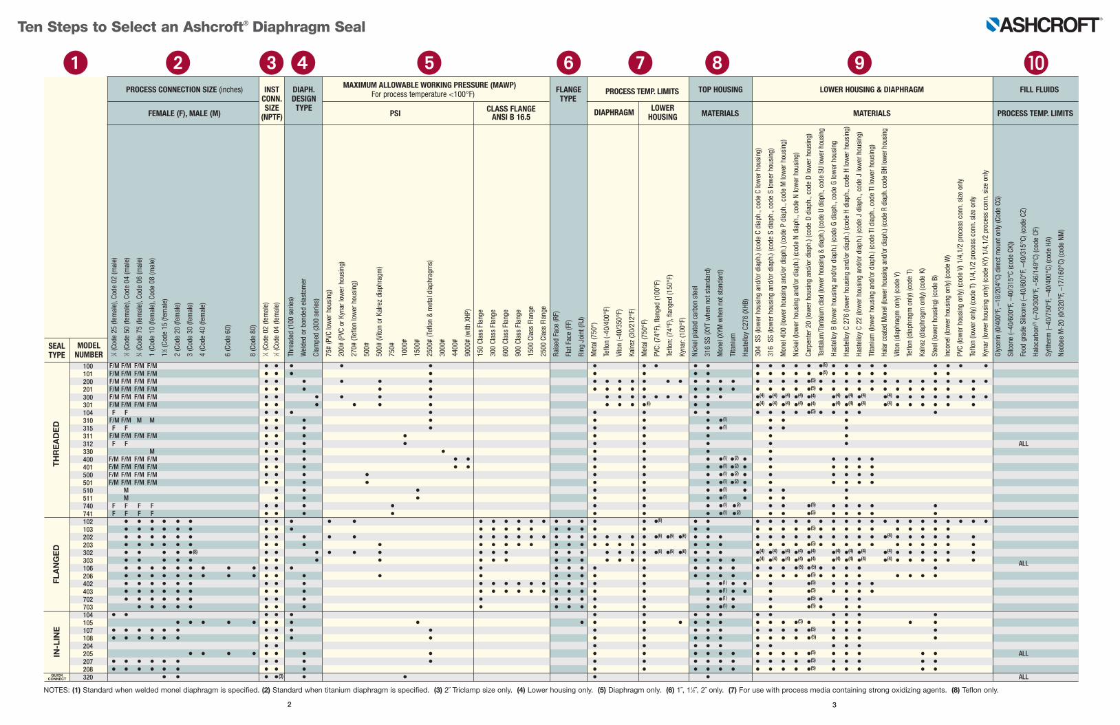
MAXIMUM ALLOWABLE WORKING PRESSURE (MAWP) PROCESS CONNECTION SIZE (inches) INST DIAPH. FLANGE PROCESS TEMP. LIMITS TOP HOUSING LOWER HOUSING & DIAPHRAGM FILL FLUIDS CONN. DESIGN For process temperature <100°F) TYPE
FEMALE (F), MALE (M) SIZE TYPE
PSI CLASS FLANGE DIAPHRAGM LOWER
MATERIALS MATERIALS PROCESS TEMP. LIMITS (NPTF) ANSI B 16.5 HOUSING
NOTES: (1) Standard when welded monel diaphragm is specified. (2) Standard when titanium diaphragm is specified. (3) 2˝ Triclamp size only. (4) Lower housing only. (5) Diaphragm only. (6) 1˝, 11⁄2˝, 2˝ only. (7) For use with process media containing strong oxidizing agents. (8) Teflon only.
Ten Steps to Select an Ashcroft® Diaphragm Seal
� � � � ��� �
2 3
1 ⁄4(Cod
e 25
(fem
ale), C
ode 02
(male)
1 ⁄2(Cod
e 50
(fem
ale), C
ode 04
(male)
3 ⁄4(Cod
e 75
(fem
ale), C
ode 06
(male)
1 (Cod
e 10
(fem
ale), C
ode 08
(male)
11⁄2(Cod
e 15
(fem
ale)
2 (Cod
e 20
(fem
ale)
3 (Cod
e 30
(fem
ale)
4 (Cod
e 40
(fem
ale)
6 (Cod
e 60
)
8 (Cod
e 80
)
1 ⁄4(Cod
e 02
(fem
ale)
1 ⁄2(Cod
e 04
(fem
ale)
Th
read
ed (1
00 series)
Welde
d or bon
ded elastomer
Clam
ped (300
series)
75
# (PVC
lower hou
sing
)
20
0# (P
VC or K
ynar lo
wer hou
sing
)
27
0# (T
eflon lower hou
sing
)
50
0#
50
0# (V
iton or Kalrez diap
hrag
m)
75
0#
10
00#
15
00#
25
00# (Teflon & metal diaph
ragm
s)
30
00#
44
00#
90
00# (w
ith XHP
)
15
0 Class Flan
ge
30
0 Class Flan
ge
60
0 Class Flan
ge
90
0 Class Flan
ge
15
00 Class Flang
e
25
00 Class Flang
e
Ra
ised
Fac
e (RF)
Flat Fac
e (FF)
Ring
Joint (R
J)
Metal (7
50°)
Teflo
n (-40
/400
°F)
Viton (-40
/350
°F)
Ka
lrez (30/21
2°F)
Metal (7
50°F)
PV
C: (7
4°F), flang
ed (1
00°F)
Teflo
n: (7
4°F), flang
ed (1
50°F)
Ky
nar: (100
°F)
Nick
el plated ca
rbon
steel
31
6 SS
(XYT
whe
n no
t stand
ard)
Mon
el (X
YM w
hen no
t stand
ard)
Titanium
Ha
stelloy C2
76 (X
HB)
30
4 SS (lo
wer hou
sing
and
/or d
iaph
.) (cod
e C diap
h., c
ode C lower hou
sing
)
31
6 SS (lo
wer hou
sing
and
/or d
iaph
.) (cod
e S diap
h., c
ode S lower hou
sing
)
Mon
el 400
(low
er hou
sing
and
/or d
iaph
.) (cod
e P diap
h., c
ode M lo
wer hou
sing
)
Nick
el (low
er hou
sing
and
/or d
iaph
.) (cod
e N diap
h., c
ode N lower hou
sing
)
Ca
rpen
ter 2
0 (lo
wer hou
sing
and
/or d
iaph
.) (cod
e D diap
h., c
ode D lower hou
sing
)
Tantalum
/Tan
talum clad (lower hou
sing
& diaph
.) (cod
e U diap
h., cod
e SU
lower hou
sing
Ha
stell oy B (lo
wer hou
sing
and
/or d
iaph
.) (cod
e G diap
h., c
ode G lower hou
sing
Ha
stelloy C 27
6 (lo
wer hou
sing
and
/or d
iaph
.) (cod
e H diap
h., c
ode H lower hou
sing
)
Ha
stelloy C 22
(low
er hou
sing
and
/or d
iaph
.) (cod
e J diap
h., c
ode J lower hou
sing
)
Titanium
(low
er hou
sing
and
/or d
iaph
.) (cod
e TI diaph
., co
de TI low
er hou
sing
)
Ha
lar c
oated Mon
el (low
er hou
sing
and
/or d
iaph
.) (cod
e R diap
h. cod
e BH
lower hou
sing
Viton (diaph
ragm
only) (c
ode Y)
Teflo
n (diaph
ragm
only) (c
ode T)
Ka
lrez (diaph
ragm
only) (c
ode K)
Stee
l (lower hou
sing
) (co
de B)
Inco
nel (lower hou
sing
only) (c
ode W)
PV
C (lo
wer hou
sing
only) (c
ode V) 1/4,1/2 proce
ss con
n. size on
ly
Teflo
n (lo
wer only) (c
ode T) 1/4,1/2 proce
ss con
n. size on
ly
Ky
nar (lower hou
sing
only) (c
ode KY
) 1/4,1/2 proce
ss con
n. size on
ly
Glycerin (0
/400
°F, –
18/204
°C) d
irect m
ount only (Cod
e CG
)
Silcon
e (–40
/600
°F, –
40/315
°C (c
ode CK
))
Fo
od grade
Silico
ne (–
40/600
°F, –
40/315
°C) (co
de CZ)
Ha
loca
rbon
(7)(–70
/300
°F, –
56/149
°C) (co
de CF)
Sy
ltherm (–
40/750
°F, –
40/400
°C) (co
de HA)
Ne
obee
M-20 (0/320
°F, –
17/160
°C) (co
de NM)
MODELNUMBER
SEALTYPE
Ash Bul S-10 TTS.qxp_layout 4/1/15 10:36 AM Page 2


![M L E C D ; N M C B G ? C ; > H I L M C E ; C E I K K @ E ...yaosobenniy.ru/files/upload/Ivanov_E.S.,_Demyanchyk_L.N.,_Demyan… · K Z g d l I _ l _ j [ m j ] B a ^ Z l _ e v k l](https://img.pdfslide.us/doc/110x75/5fa84a3b50444c4e630d2b35/m-l-e-c-d-n-m-c-b-g-c-h-i-l-m-c-e-c-e-i-k-k-e-demyanchyklndemyan.jpg)