Embed Size (px)
Citation preview
ScienceDirect
Available online at www.sciencedirect.com
Available online at www.sciencedirect.com
ScienceDirect
Structural Integrity Procedia 00 (2016) 000–000 www.elsevier.com/locate/procedia
2452-3216 © 2016 The Authors. Published by Elsevier B.V. Peer-review under responsibility of the Scientific Committee of PCF 2016.
XV Portuguese Conference on Fracture, PCF 2016, 10-12 February 2016, Paço de Arcos, Portugal
Thermo-mechanical modeling of a high pressure turbine blade of an airplane gas turbine engine
P. Brandãoa, V. Infanteb, A.M. Deusc* aDepartment of Mechanical Engineering, Instituto Superior Técnico, Universidade de Lisboa, Av. Rovisco Pais, 1, 1049-001 Lisboa,
Portugal bIDMEC, Department of Mechanical Engineering, Instituto Superior Técnico, Universidade de Lisboa, Av. Rovisco Pais, 1, 1049-001 Lisboa,
Portugal cCeFEMA, Department of Mechanical Engineering, Instituto Superior Técnico, Universidade de Lisboa, Av. Rovisco Pais, 1, 1049-001 Lisboa,
Portugal
Abstract
During their operation, modern aircraft engine components are subjected to increasingly demanding operating conditions, especially the high pressure turbine (HPT) blades. Such conditions cause these parts to undergo different types of time-dependent degradation, one of which is creep. A model using the finite element method (FEM) was developed, in order to be able to predict the creep behaviour of HPT blades. Flight data records (FDR) for a specific aircraft, provided by a commercial aviation company, were used to obtain thermal and mechanical data for three different flight cycles. In order to create the 3D model needed for the FEM analysis, a HPT blade scrap was scanned, and its chemical composition and material properties were obtained. The data that was gathered was fed into the FEM model and different simulations were run, first with a simplified 3D rectangular block shape, in order to better establish the model, and then with the real 3D mesh obtained from the blade scrap. The overall expected behaviour in terms of displacement was observed, in particular at the trailing edge of the blade. Therefore such a model can be useful in the goal of predicting turbine blade life, given a set of FDR data. © 2016 The Authors. Published by Elsevier B.V. Peer-review under responsibility of the Scientific Committee of PCF 2016.
Keywords: High Pressure Turbine Blade; Creep; Finite Element Method; 3D Model; Simulation.
* Corresponding author. Tel.: +351 218419991.
E-mail address: [email protected]
Procedia Structural Integrity 13 (2018) 953–958
2452-3216 2018 The Authors. Published by Elsevier B.V.Peer-review under responsibility of the ECF22 organizers.10.1016/j.prostr.2018.12.178
Available online at www.sciencedirect.com
ScienceDirect
Structural Integrity Procedia 00 (2018) 000–000 www.elsevier.com/locate/procedia
2452-3216 © 2018 The Authors. Published by Elsevier B.V. Peer-review under responsibility of the ECF22 organizers.
ECF22 - Loading and Environmental effects on Structural Integrity
A numerical analysis of the effects of manufacturing processes on material pre-strain in offshore wind monopiles Satya Anandavijayan*, Ali Mehmanparast, Feargal Brennan
aOffshore energy engineering centre, Cranfield University, MK43 0AL, UK bNaval architecture and marine engineering, University of Strathclyde, G4 0LZ, UK
Abstract
The majority of offshore wind turbines in Europe are supported by monopile type foundation structures. Monopiles are made of large thickness steel plates which are longitudinally welded to fabricate “cans” and these cans are subsequently welded around the circumference to manufacture a monopile. Monopile structures can have diameters of 4-10m, with wall thicknesses of 40-150mm. To achieve the cylindrical shape in individual cans, large thickness steel plates are typically cold formed via the three-roll bending process. During forming of these plates, the material is subjected to plastic pre-strain, which subsequently influences the fracture and fatigue properties of monopile structures. In this study, a finite element model has been developed to predict the pre-straining levels in monopiles of different dimensions. To determine the influence of numerous manufacturing practices, a sensitivity analysis of different factors has been conducted. These include fabrication dependent variables such as the influence of friction coefficient and bending force, and geometry dependent factors such as plate thickness, length, and distance between rollers. From the numerical results, a range of expected material pre-strain levels have been identified and presented in this paper. © 2018 The Authors. Published by Elsevier B.V. Peer-review under responsibility of the ECF22 organizers.
Keywords: material pre-strain; monopile; fatigue; fracture; S355; finite element analysis; three roll bending
1. Introduction
Renewable energy is predicted to be one of the fastest growing maritime sectors. Currently, wind energy already meets 11% of the EU’s power demand and is predicted that by the year 2030, its installed capacity will reach up to 23% of Europe’s total electricity demand (European Wind Energy Association, 2017). For this to be technically feasible, it is crucial for new offshore concepts and designs to be developed in order to utilize the deeper, larger expanses and wind potential of areas such as the Mediterranean, Atlantic and North Sea waters (European Wind Energy Association, 2013).
10.1016/j.prostr.2018.12.178 2452-3216
© 2018 The Authors. Published by Elsevier B.V.Peer-review under responsibility of the ECF22 organizers.
Available online at www.sciencedirect.com
ScienceDirect
Structural Integrity Procedia 00 (2018) 000–000 www.elsevier.com/locate/procedia
2452-3216 © 2018 The Authors. Published by Elsevier B.V. Peer-review under responsibility of the ECF22 organizers.
ECF22 - Loading and Environmental effects on Structural Integrity
A numerical analysis of the effects of manufacturing processes on material pre-strain in offshore wind monopiles Satya Anandavijayan*, Ali Mehmanparast, Feargal Brennan
aOffshore energy engineering centre, Cranfield University, MK43 0AL, UK bNaval architecture and marine engineering, University of Strathclyde, G4 0LZ, UK
Abstract
The majority of offshore wind turbines in Europe are supported by monopile type foundation structures. Monopiles are made of large thickness steel plates which are longitudinally welded to fabricate “cans” and these cans are subsequently welded around the circumference to manufacture a monopile. Monopile structures can have diameters of 4-10m, with wall thicknesses of 40-150mm. To achieve the cylindrical shape in individual cans, large thickness steel plates are typically cold formed via the three-roll bending process. During forming of these plates, the material is subjected to plastic pre-strain, which subsequently influences the fracture and fatigue properties of monopile structures. In this study, a finite element model has been developed to predict the pre-straining levels in monopiles of different dimensions. To determine the influence of numerous manufacturing practices, a sensitivity analysis of different factors has been conducted. These include fabrication dependent variables such as the influence of friction coefficient and bending force, and geometry dependent factors such as plate thickness, length, and distance between rollers. From the numerical results, a range of expected material pre-strain levels have been identified and presented in this paper. © 2018 The Authors. Published by Elsevier B.V. Peer-review under responsibility of the ECF22 organizers.
Keywords: material pre-strain; monopile; fatigue; fracture; S355; finite element analysis; three roll bending
1. Introduction
Renewable energy is predicted to be one of the fastest growing maritime sectors. Currently, wind energy already meets 11% of the EU’s power demand and is predicted that by the year 2030, its installed capacity will reach up to 23% of Europe’s total electricity demand (European Wind Energy Association, 2017). For this to be technically feasible, it is crucial for new offshore concepts and designs to be developed in order to utilize the deeper, larger expanses and wind potential of areas such as the Mediterranean, Atlantic and North Sea waters (European Wind Energy Association, 2013).
954 Satya Anandavijayan et al. / Procedia Structural Integrity 13 (2018) 953–9582 Author name / Structural Integrity Procedia 00 (2018) 000–000
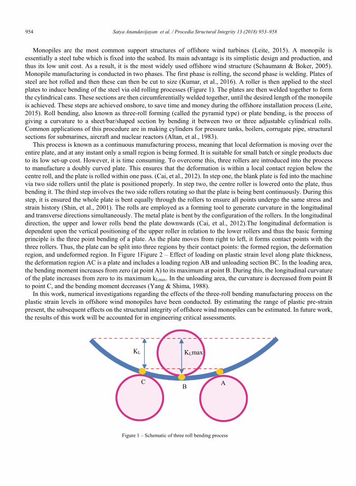
Monopiles are the most common support structures of offshore wind turbines (Leite, 2015). A monopile is essentially a steel tube which is fixed into the seabed. Its main advantage is its simplistic design and production, and thus its low unit cost. As a result, it is the most widely used offshore wind structure (Schaumann & Boker, 2005). Monopile manufacturing is conducted in two phases. The first phase is rolling, the second phase is welding. Plates of steel are hot rolled and then these can then be cut to size (Kumar, et al., 2016). A roller is then applied to the steel plates to induce bending of the steel via old rolling processes (Figure 1). The plates are then welded together to form the cylindrical cans. These sections are then circumferentially welded together, until the desired length of the monopile is achieved. These steps are achieved onshore, to save time and money during the offshore installation process (Leite, 2015). Roll bending, also known as three-roll forming (called the pyramid type) or plate bending, is the process of giving a curvature to a sheet/bar/shaped section by bending it between two or three adjustable cylindrical rolls. Common applications of this procedure are in making cylinders for pressure tanks, boilers, corrugate pipe, structural sections for submarines, aircraft and nuclear reactors (Altan, et al., 1983).
This process is known as a continuous manufacturing process, meaning that local deformation is moving over the entire plate, and at any instant only a small region is being formed. It is suitable for small batch or single products due to its low set-up cost. However, it is time consuming. To overcome this, three rollers are introduced into the process to manufacture a doubly curved plate. This ensures that the deformation is within a local contact region below the centre roll, and the plate is rolled within one pass. (Cai, et al., 2012). In step one, the blank plate is fed into the machine via two side rollers until the plate is positioned properly. In step two, the centre roller is lowered onto the plate, thus bending it. The third step involves the two side rollers rotating so that the plate is being bent continuously. During this step, it is ensured the whole plate is bent equally through the rollers to ensure all points undergo the same stress and strain history (Shin, et al., 2001). The rolls are employed as a forming tool to generate curvature in the longitudinal and transverse directions simultaneously. The metal plate is bent by the configuration of the rollers. In the longitudinal direction, the upper and lower rolls bend the plate downwards (Cai, et al., 2012).The longitudinal deformation is dependent upon the vertical positioning of the upper roller in relation to the lower rollers and thus the basic forming principle is the three point bending of a plate. As the plate moves from right to left, it forms contact points with the three rollers. Thus, the plate can be split into three regions by their contact points: the formed region, the deformation region, and undeformed region. In Figure 1Figure 2 – Effect of loading on plastic strain level along plate thickness, the deformation region AC is a plate and includes a loading region AB and unloading section BC. In the loading area, the bending moment increases from zero (at point A) to its maximum at point B. During this, the longitudinal curvature of the plate increases from zero to its maximum kLmax. In the unloading area, the curvature is decreased from point B to point C, and the bending moment decreases (Yang & Shima, 1988).
In this work, numerical investigations regarding the effects of the three-roll bending manufacturing process on the plastic strain levels in offshore wind monopiles have been conducted. By estimating the range of plastic pre-strain present, the subsequent effects on the structural integrity of offshore wind monopiles can be estimated. In future work, the results of this work will be accounted for in engineering critical assessments.
KLmax
AB C
Figure 1 – Schematic of three roll bending process
KL
S. Anandavijayan/ Structural Integrity Procedia 00 (2018) 000–000 3
Nomenclature
σ|0 yield stress εp plastic strain γ material coefficient c length of plate C material coefficient d deflection E Young’s Modulus KLmax maximum curvature R radius
2. Finite Element Model
2.1. Dimensions and Material Properties
Static bending simulations were run on a symmetrical quarter symmetry model of the 3 roll bending set up. The top and bottom rollers were modelled with 1m diameter, and 3m roller length. The distance between the rollers was 2m, However, in the roller diameter simulation, the diameter of the rollers were changed by +/- 0.2m determine the sensitivity of S355 to this change. The plate was modelled with a thickness of 60mm. In plate thickness simulations, the plate thickness varied between 55m and 65mm to determine the sensitivity of the plastic strain within the plate to this change. The material used in this work is S355 structural steel which is widely used in the fabrication of monopiles. The material properties were gathered from experimental data from previous work, and calculating the required parameters (Mrozinski & Piotrowski, 2006). The Young’s modulus was calculated from literature values (de Jesus, et al., 2012). As recommended in the Abaqus documentation, the combined isotropic/kinematic hardening model was used (Abaqus documentation). The kinematic hardening behaviour was characterised using the parameters σ|0, C, and γ where σ|0 is the yield stress of the material, while C and γ are material coefficients. The yield stress of the material was taken as 400 MPa in this study.
2.2. Element Type and Mesh Sensitivity Analysis
The plate was meshed using C3D8R elements. The rollers were meshed using discrete rigid elements. The mesh of the entire geometry was refined in both the longitudinal and transverse directions to increase the number of elements and nodes and thus the mesh density. The mesh was refined by increasing the number of elements and the simulation was run and rerun at varying mesh intensities. A path was created in both the longitudinal direction (at y = 0), and in the transverse direction to plot the values from the mesh sensitivity analysis at the same points. Once the results had converged on the graphs, it was assumed that the optimum mesh density for each model had been identified correctly. From the mesh sensitivity analysis, it was concluded that the optimum mesh density was 68073 elements for the whole model. This was obtained when the element size in the regions of interest was reduced to 0.001m. At the areas of contact, a denser mesh was generated using single bias picking.
3. Results and Discussion
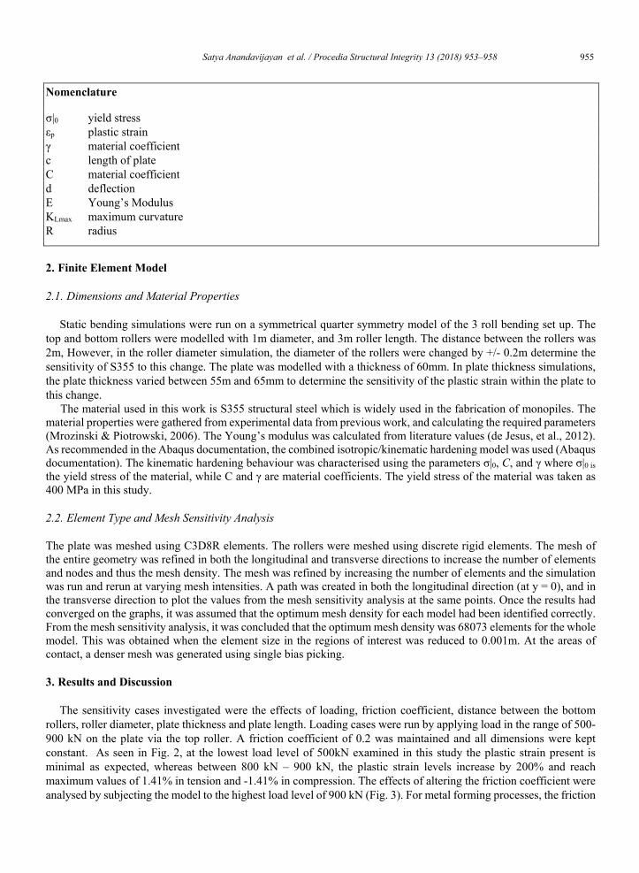
The sensitivity cases investigated were the effects of loading, friction coefficient, distance between the bottom rollers, roller diameter, plate thickness and plate length. Loading cases were run by applying load in the range of 500-900 kN on the plate via the top roller. A friction coefficient of 0.2 was maintained and all dimensions were kept constant. As seen in Fig. 2, at the lowest load level of 500kN examined in this study the plastic strain present is minimal as expected, whereas between 800 kN – 900 kN, the plastic strain levels increase by 200% and reach maximum values of 1.41% in tension and -1.41% in compression. The effects of altering the friction coefficient were analysed by subjecting the model to the highest load level of 900 kN (Fig. 3). For metal forming processes, the friction
Satya Anandavijayan et al. / Procedia Structural Integrity 13 (2018) 953–958 9552 Author name / Structural Integrity Procedia 00 (2018) 000–000
Monopiles are the most common support structures of offshore wind turbines (Leite, 2015). A monopile is essentially a steel tube which is fixed into the seabed. Its main advantage is its simplistic design and production, and thus its low unit cost. As a result, it is the most widely used offshore wind structure (Schaumann & Boker, 2005). Monopile manufacturing is conducted in two phases. The first phase is rolling, the second phase is welding. Plates of steel are hot rolled and then these can then be cut to size (Kumar, et al., 2016). A roller is then applied to the steel plates to induce bending of the steel via old rolling processes (Figure 1). The plates are then welded together to form the cylindrical cans. These sections are then circumferentially welded together, until the desired length of the monopile is achieved. These steps are achieved onshore, to save time and money during the offshore installation process (Leite, 2015). Roll bending, also known as three-roll forming (called the pyramid type) or plate bending, is the process of giving a curvature to a sheet/bar/shaped section by bending it between two or three adjustable cylindrical rolls. Common applications of this procedure are in making cylinders for pressure tanks, boilers, corrugate pipe, structural sections for submarines, aircraft and nuclear reactors (Altan, et al., 1983).
This process is known as a continuous manufacturing process, meaning that local deformation is moving over the entire plate, and at any instant only a small region is being formed. It is suitable for small batch or single products due to its low set-up cost. However, it is time consuming. To overcome this, three rollers are introduced into the process to manufacture a doubly curved plate. This ensures that the deformation is within a local contact region below the centre roll, and the plate is rolled within one pass. (Cai, et al., 2012). In step one, the blank plate is fed into the machine via two side rollers until the plate is positioned properly. In step two, the centre roller is lowered onto the plate, thus bending it. The third step involves the two side rollers rotating so that the plate is being bent continuously. During this step, it is ensured the whole plate is bent equally through the rollers to ensure all points undergo the same stress and strain history (Shin, et al., 2001). The rolls are employed as a forming tool to generate curvature in the longitudinal and transverse directions simultaneously. The metal plate is bent by the configuration of the rollers. In the longitudinal direction, the upper and lower rolls bend the plate downwards (Cai, et al., 2012).The longitudinal deformation is dependent upon the vertical positioning of the upper roller in relation to the lower rollers and thus the basic forming principle is the three point bending of a plate. As the plate moves from right to left, it forms contact points with the three rollers. Thus, the plate can be split into three regions by their contact points: the formed region, the deformation region, and undeformed region. In Figure 1Figure 2 – Effect of loading on plastic strain level along plate thickness, the deformation region AC is a plate and includes a loading region AB and unloading section BC. In the loading area, the bending moment increases from zero (at point A) to its maximum at point B. During this, the longitudinal curvature of the plate increases from zero to its maximum kLmax. In the unloading area, the curvature is decreased from point B to point C, and the bending moment decreases (Yang & Shima, 1988).
In this work, numerical investigations regarding the effects of the three-roll bending manufacturing process on the plastic strain levels in offshore wind monopiles have been conducted. By estimating the range of plastic pre-strain present, the subsequent effects on the structural integrity of offshore wind monopiles can be estimated. In future work, the results of this work will be accounted for in engineering critical assessments.
KLmax
AB C
Figure 1 – Schematic of three roll bending process
KL
S. Anandavijayan/ Structural Integrity Procedia 00 (2018) 000–000 3
Nomenclature
σ|0 yield stress εp plastic strain γ material coefficient c length of plate C material coefficient d deflection E Young’s Modulus KLmax maximum curvature R radius
2. Finite Element Model
2.1. Dimensions and Material Properties
Static bending simulations were run on a symmetrical quarter symmetry model of the 3 roll bending set up. The top and bottom rollers were modelled with 1m diameter, and 3m roller length. The distance between the rollers was 2m, However, in the roller diameter simulation, the diameter of the rollers were changed by +/- 0.2m determine the sensitivity of S355 to this change. The plate was modelled with a thickness of 60mm. In plate thickness simulations, the plate thickness varied between 55m and 65mm to determine the sensitivity of the plastic strain within the plate to this change. The material used in this work is S355 structural steel which is widely used in the fabrication of monopiles. The material properties were gathered from experimental data from previous work, and calculating the required parameters (Mrozinski & Piotrowski, 2006). The Young’s modulus was calculated from literature values (de Jesus, et al., 2012). As recommended in the Abaqus documentation, the combined isotropic/kinematic hardening model was used (Abaqus documentation). The kinematic hardening behaviour was characterised using the parameters σ|0, C, and γ where σ|0 is the yield stress of the material, while C and γ are material coefficients. The yield stress of the material was taken as 400 MPa in this study.
2.2. Element Type and Mesh Sensitivity Analysis
The plate was meshed using C3D8R elements. The rollers were meshed using discrete rigid elements. The mesh of the entire geometry was refined in both the longitudinal and transverse directions to increase the number of elements and nodes and thus the mesh density. The mesh was refined by increasing the number of elements and the simulation was run and rerun at varying mesh intensities. A path was created in both the longitudinal direction (at y = 0), and in the transverse direction to plot the values from the mesh sensitivity analysis at the same points. Once the results had converged on the graphs, it was assumed that the optimum mesh density for each model had been identified correctly. From the mesh sensitivity analysis, it was concluded that the optimum mesh density was 68073 elements for the whole model. This was obtained when the element size in the regions of interest was reduced to 0.001m. At the areas of contact, a denser mesh was generated using single bias picking.
3. Results and Discussion
The sensitivity cases investigated were the effects of loading, friction coefficient, distance between the bottom rollers, roller diameter, plate thickness and plate length. Loading cases were run by applying load in the range of 500-900 kN on the plate via the top roller. A friction coefficient of 0.2 was maintained and all dimensions were kept constant. As seen in Fig. 2, at the lowest load level of 500kN examined in this study the plastic strain present is minimal as expected, whereas between 800 kN – 900 kN, the plastic strain levels increase by 200% and reach maximum values of 1.41% in tension and -1.41% in compression. The effects of altering the friction coefficient were analysed by subjecting the model to the highest load level of 900 kN (Fig. 3). For metal forming processes, the friction
956 Satya Anandavijayan et al. / Procedia Structural Integrity 13 (2018) 953–9584 Author name / Structural Integrity Procedia 00 (2018) 000–000
coefficient is usually around 0.2-0.3 (Z Marciniac, et al., 2002) (Chudasama & Raval, 2015). The simulations results show similar trends when different values of friction coefficient were employed in the analysis. However, increasing the friction coefficient from 0.2 to 1.0 decreased the plastic tensile strain from 1.42% to 1.18%, giving a reduction in plastic strain which is approximately 13%.
The roller diameter was increased from 1 to 1.2 m for one case and decreased from 1 to 0.8 m for another. The load
level for the simulation was set at 900 kN at a friction coefficient of 0.2, and the thickness of the plate remained as 60 mm. The distance between the two bottom rollers remained at 1m. Decreasing the roller diameter by 0.2 m resulted in the plastic strain increasing from 1.44% to 1.6%, which is a 10% increase in plastic strain (Errore. L'origine riferimento non è stata trovata.). Increasing the roller diameter by 0.2 m resulted in a very minimal decrease in plastic strain. This suggests that changing the roller diameter will not play a significant part in altering the pre-strain level of S355 plates. The length of plate hanging past the bottom rollers was increased to determine if this had any effect on the plastic pre-strain levels (Errore. L'origine riferimento non è stata trovata.). This case was run to determine if the plate length would affect the plastic strain level during the fabrication process. It was noticed that increasing the length of plate extending from the roller can result in a decrease in plastic strain levels. As the plate length increased the overall mass of the plate increased making it more difficult to bend in compression. Thus a decrease in plastic strain was observed. Increasing the overhang of sheet from 1 to 3 m can reduce the plastic strain by approximately 22%, from a tensile plastic strain of 1.45% to 1.18%. The bottom rollers were moved from a distance of 2 m between the rollers, to 2.5m 3m. The diameter of the rollers and the plate were unchanged, and the friction coefficient was kept at 0.2. The load level used for the simulation was 900 kN. From the finite element results, it can be concluded that re-positioning the bottom rollers to create more distance will not significantly affect the level of plastic strain present in the material (Errore. L'origine riferimento non è stata trovata.). The maximum plastic strain in tension was 1.45%, and -1.45% in compression.
The plate thickness was increased from 60 mm to 55 mm and 65 mm and were subjected to a load of 900 kN. The friction coefficient was maintained at 0.2 and all dimensions were kept constant. From the simulations, a 60 mm plate thickness when subjected to a load of 900 kN gives a maximum tensile plastic strain of 1.45%. Reducing the wall thickness by 5mm results in an increase in plastic strain by 190%. Increasing the wall thickness by 5mm resulted in a reduction in plastic strain by 245%. From these results its can be seen how significant a 5mm difference in plate thickness can make a significant difference in plastic strain level (Errore. L'origine riferimento non è stata trovata.). The displacement outputs from the simulations were used to
Figure 2 – Effect of loading on plastic strain level along plate thicknessFigure 3 – Effect of friction coefficient on plastic strain level
along the plate thickness
S. Anandavijayan/ Structural Integrity Procedia 00 (2018) 000–000 5
calculate the radius of curvature and the corresponding maximum possible diameter from these results (Table 1). Displacement values were taken from cases run at a load level of 900 kN, with a friction coefficient of 0.2.
Figure 4 - Effect of the thickness of plates on the plastic strain level Figure 5 – Effect of the distance between the bottom rollers on the plastic strain level across the thickness.
Figure 6 – Effect of roller diameter on plastic strain across the plate thickness.
Figure 7 – Effect of plate length on the plastic strain through the thickness of the plate.
The distance between the rollers remained at 2 m. The equation used to calculate the radius was:
� �� 𝑐𝑐� � �𝑑𝑑�8𝑑𝑑
where c is the distance between the rollers, d is the displacement, and R is the radius. From the results in Table 1, it can be noted that with each 5mm increase in wall thickness, the radius of curvature
will almost double. Further studies will be conducted in future work to examine the load level effects on radius of curvature. From the overall results, the maximum plastic strain range obtained from of finite element cases from load levels, friction coefficients, and distance between rollers considered was from -1.6% to 1.6% for S355 steel. However, in the case for wall thicknesses, the maximum plastic strain range was from -3.3% to 3.3%

Satya Anandavijayan et al. / Procedia Structural Integrity 13 (2018) 953–958 9574 Author name / Structural Integrity Procedia 00 (2018) 000–000
coefficient is usually around 0.2-0.3 (Z Marciniac, et al., 2002) (Chudasama & Raval, 2015). The simulations results show similar trends when different values of friction coefficient were employed in the analysis. However, increasing the friction coefficient from 0.2 to 1.0 decreased the plastic tensile strain from 1.42% to 1.18%, giving a reduction in plastic strain which is approximately 13%.
The roller diameter was increased from 1 to 1.2 m for one case and decreased from 1 to 0.8 m for another. The load
level for the simulation was set at 900 kN at a friction coefficient of 0.2, and the thickness of the plate remained as 60 mm. The distance between the two bottom rollers remained at 1m. Decreasing the roller diameter by 0.2 m resulted in the plastic strain increasing from 1.44% to 1.6%, which is a 10% increase in plastic strain (Errore. L'origine riferimento non è stata trovata.). Increasing the roller diameter by 0.2 m resulted in a very minimal decrease in plastic strain. This suggests that changing the roller diameter will not play a significant part in altering the pre-strain level of S355 plates. The length of plate hanging past the bottom rollers was increased to determine if this had any effect on the plastic pre-strain levels (Errore. L'origine riferimento non è stata trovata.). This case was run to determine if the plate length would affect the plastic strain level during the fabrication process. It was noticed that increasing the length of plate extending from the roller can result in a decrease in plastic strain levels. As the plate length increased the overall mass of the plate increased making it more difficult to bend in compression. Thus a decrease in plastic strain was observed. Increasing the overhang of sheet from 1 to 3 m can reduce the plastic strain by approximately 22%, from a tensile plastic strain of 1.45% to 1.18%. The bottom rollers were moved from a distance of 2 m between the rollers, to 2.5m 3m. The diameter of the rollers and the plate were unchanged, and the friction coefficient was kept at 0.2. The load level used for the simulation was 900 kN. From the finite element results, it can be concluded that re-positioning the bottom rollers to create more distance will not significantly affect the level of plastic strain present in the material (Errore. L'origine riferimento non è stata trovata.). The maximum plastic strain in tension was 1.45%, and -1.45% in compression.
The plate thickness was increased from 60 mm to 55 mm and 65 mm and were subjected to a load of 900 kN. The friction coefficient was maintained at 0.2 and all dimensions were kept constant. From the simulations, a 60 mm plate thickness when subjected to a load of 900 kN gives a maximum tensile plastic strain of 1.45%. Reducing the wall thickness by 5mm results in an increase in plastic strain by 190%. Increasing the wall thickness by 5mm resulted in a reduction in plastic strain by 245%. From these results its can be seen how significant a 5mm difference in plate thickness can make a significant difference in plastic strain level (Errore. L'origine riferimento non è stata trovata.). The displacement outputs from the simulations were used to
Figure 2 – Effect of loading on plastic strain level along plate thicknessFigure 3 – Effect of friction coefficient on plastic strain level
along the plate thickness
S. Anandavijayan/ Structural Integrity Procedia 00 (2018) 000–000 5
calculate the radius of curvature and the corresponding maximum possible diameter from these results (Table 1). Displacement values were taken from cases run at a load level of 900 kN, with a friction coefficient of 0.2.
Figure 4 - Effect of the thickness of plates on the plastic strain level Figure 5 – Effect of the distance between the bottom rollers on the plastic strain level across the thickness.
Figure 6 – Effect of roller diameter on plastic strain across the plate thickness.
Figure 7 – Effect of plate length on the plastic strain through the thickness of the plate.
The distance between the rollers remained at 2 m. The equation used to calculate the radius was:
� �� 𝑐𝑐� � �𝑑𝑑�8𝑑𝑑
where c is the distance between the rollers, d is the displacement, and R is the radius. From the results in Table 1, it can be noted that with each 5mm increase in wall thickness, the radius of curvature
will almost double. Further studies will be conducted in future work to examine the load level effects on radius of curvature. From the overall results, the maximum plastic strain range obtained from of finite element cases from load levels, friction coefficients, and distance between rollers considered was from -1.6% to 1.6% for S355 steel. However, in the case for wall thicknesses, the maximum plastic strain range was from -3.3% to 3.3%
958 Satya Anandavijayan et al. / Procedia Structural Integrity 13 (2018) 953–9586 Author name / Structural Integrity Procedia 00 (2018) 000–000
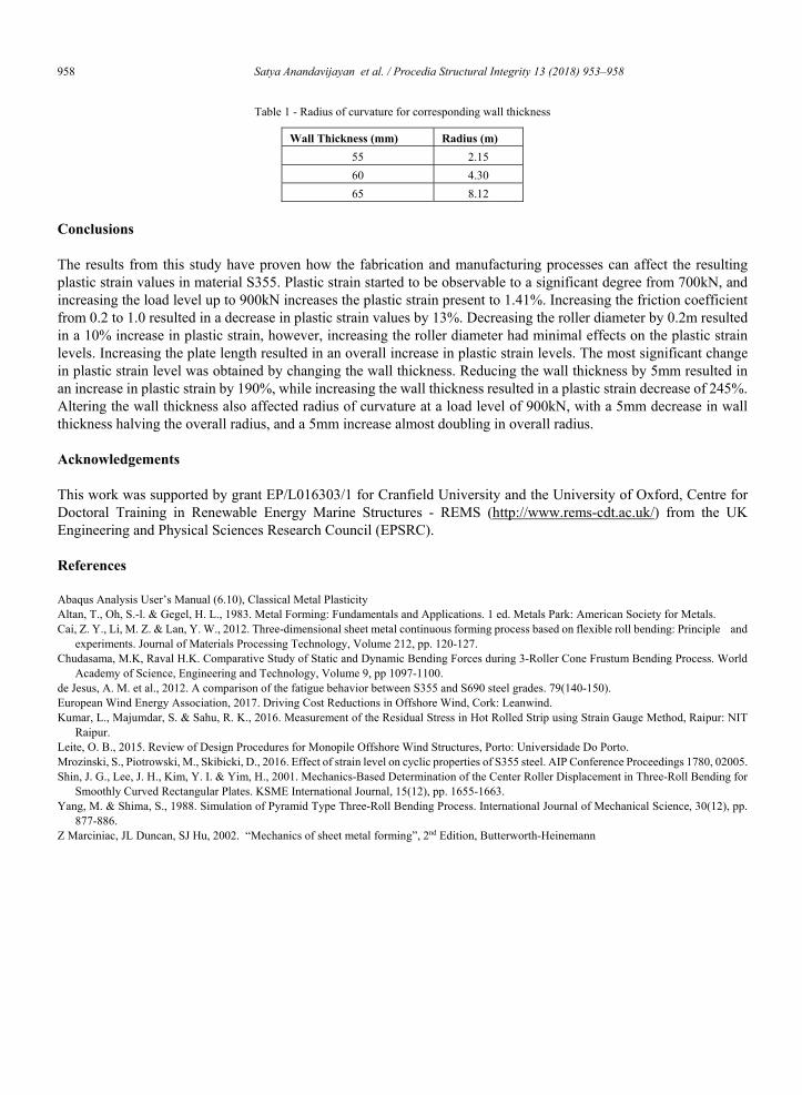
Table 1 - Radius of curvature for corresponding wall thickness
Wall Thickness (mm) Radius (m) 55 2.15 60 4.30 65 8.12
Conclusions
The results from this study have proven how the fabrication and manufacturing processes can affect the resulting plastic strain values in material S355. Plastic strain started to be observable to a significant degree from 700kN, and increasing the load level up to 900kN increases the plastic strain present to 1.41%. Increasing the friction coefficient from 0.2 to 1.0 resulted in a decrease in plastic strain values by 13%. Decreasing the roller diameter by 0.2m resulted in a 10% increase in plastic strain, however, increasing the roller diameter had minimal effects on the plastic strain levels. Increasing the plate length resulted in an overall increase in plastic strain levels. The most significant change in plastic strain level was obtained by changing the wall thickness. Reducing the wall thickness by 5mm resulted in an increase in plastic strain by 190%, while increasing the wall thickness resulted in a plastic strain decrease of 245%. Altering the wall thickness also affected radius of curvature at a load level of 900kN, with a 5mm decrease in wall thickness halving the overall radius, and a 5mm increase almost doubling in overall radius.
Acknowledgements This work was supported by grant EP/L016303/1 for Cranfield University and the University of Oxford, Centre for Doctoral Training in Renewable Energy Marine Structures - REMS (http://www.rems-cdt.ac.uk/) from the UK Engineering and Physical Sciences Research Council (EPSRC).
References
Abaqus Analysis User’s Manual (6.10), Classical Metal Plasticity Altan, T., Oh, S.-l. & Gegel, H. L., 1983. Metal Forming: Fundamentals and Applications. 1 ed. Metals Park: American Society for Metals. Cai, Z. Y., Li, M. Z. & Lan, Y. W., 2012. Three-dimensional sheet metal continuous forming process based on flexible roll bending: Principle and
experiments. Journal of Materials Processing Technology, Volume 212, pp. 120-127. Chudasama, M.K, Raval H.K. Comparative Study of Static and Dynamic Bending Forces during 3-Roller Cone Frustum Bending Process. World
Academy of Science, Engineering and Technology, Volume 9, pp 1097-1100. de Jesus, A. M. et al., 2012. A comparison of the fatigue behavior between S355 and S690 steel grades. 79(140-150). European Wind Energy Association, 2017. Driving Cost Reductions in Offshore Wind, Cork: Leanwind. Kumar, L., Majumdar, S. & Sahu, R. K., 2016. Measurement of the Residual Stress in Hot Rolled Strip using Strain Gauge Method, Raipur: NIT
Raipur. Leite, O. B., 2015. Review of Design Procedures for Monopile Offshore Wind Structures, Porto: Universidade Do Porto. Mrozinski, S., Piotrowski, M., Skibicki, D., 2016. Effect of strain level on cyclic properties of S355 steel. AIP Conference Proceedings 1780, 02005. Shin, J. G., Lee, J. H., Kim, Y. I. & Yim, H., 2001. Mechanics-Based Determination of the Center Roller Displacement in Three-Roll Bending for
Smoothly Curved Rectangular Plates. KSME International Journal, 15(12), pp. 1655-1663. Yang, M. & Shima, S., 1988. Simulation of Pyramid Type Three-Roll Bending Process. International Journal of Mechanical Science, 30(12), pp.
877-886. Z Marciniac, JL Duncan, SJ Hu, 2002. “Mechanics of sheet metal forming”, 2nd Edition, Butterworth-Heinemann

![Contents lists available at ScienceDirect Resuscitation · an updated CoSTR every 5years [2–5] which the ERC has subsequently ... Marios Georgiou, Tony Handley, Leo Bossaert, new](https://img.pdfslide.us/doc/110x75/5f320fe737530f6f1838a1e9/contents-lists-available-at-sciencedirect-resuscitation-an-updated-costr-every-5years.jpg)


![ScienceDirect cienceirect ScienceDirect · and. {[,], , , : . , /](https://img.pdfslide.us/doc/110x75/608077a6d3af4a2358487f59/-sciencedirect-cienceirect-sciencedirect-and-.jpg)