Embed Size (px)
Citation preview

i© 2014 ICS, Blount International Inc. Specifications are subject to change without notice. REV061914 F/N 545067
695GC / 695F4OPERATOR MANUAL

2 © 2014 ICS, Blount International Inc. Specifications are subject to change without notice. REV061914 F/N 545067
QUICK START GUIDE 3
SYMBOLS & LABELS 10
SAFETY 15
TECHNICAL SPECIFICATIONS 16
SETUP 17
OPERATION 22
MAINTENANCE 31
TROUBLESHOOTING 41
REFERENCE 42
EMISSION CONTROL WARRANTY STATEMENT 43
DECLARATION OF CONFORMITY 45
SERVICE CENTERS 46
This manual outlines the maintenance and operation of ICS® manufactured products. This is a professional tool and is soley intended for use by trained and experienced operators.
The 695GC / 695F4 chainsaw is designed to cut concrete, stone, and masonry when used with the appropriate genuine ICS Diamond Chain. Ductile iron pipe may be cut ONLY if using PowerGrit® Utility Saw Chain.
To get the maximum benefit from your saw, and ensure maximum safety, be sure to read this manual thoroughly, and periodically review safety instructions.
INTRODUCTION/TABLE OF CONTENTS
3© 2014 ICS, Blount International Inc. Specifications are subject to change without notice. REV061914 F/N 545067
QUICK START GUIDE
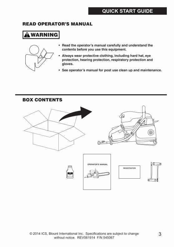
READ OPERATOR’S MANUAL
BOX CONTENTS
WARNING
• Readtheoperator’smanualcarefullyandunderstandthecontentsbeforeyouusethisequipment.
• Alwayswearprotectiveclothing,includinghardhat,eyeprotection,hearingprotection,respiratoryprotectionandgloves.
• Seeoperator’smanualforpostusecleanupandmaintenance.
4 © 2014 ICS, Blount International Inc. Specifications are subject to change without notice. REV061914 F/N 545067
QUICK START GUIDE
FUELING THE SAW
WARNING
CAUTION
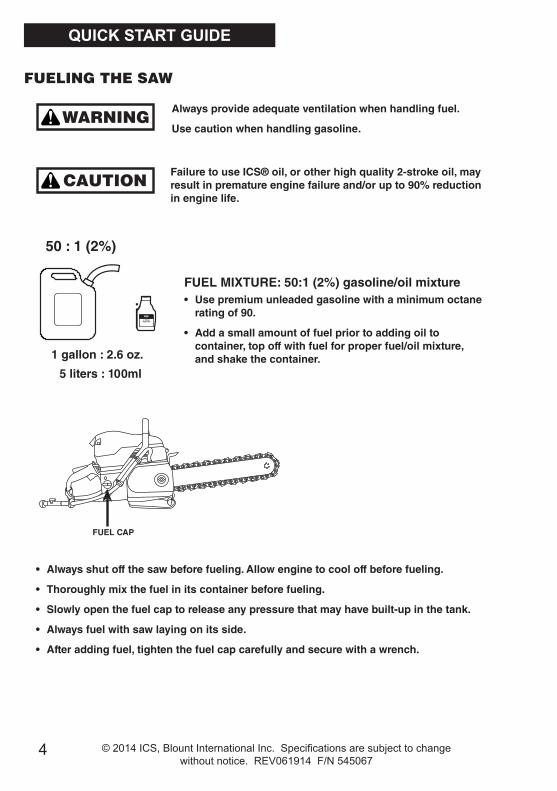
Alwaysprovideadequateventilationwhenhandlingfuel.
Usecautionwhenhandlinggasoline.
FailuretouseICS®oil,orotherhighquality2-strokeoil,mayresultinprematureenginefailureand/orupto90%reductioninenginelife.
FUELMIXTURE:50:1(2%)gasoline/oilmixture• Usepremiumunleadedgasolinewithaminimumoctane
ratingof90.
• Addasmallamountoffuelpriortoaddingoiltocontainer,topoffwithfuelforproperfuel/oilmixture,andshakethecontainer.
• Alwaysshutoffthesawbeforefueling.Allowenginetocooloffbeforefueling.
• Thoroughlymixthefuelinitscontainerbeforefueling.
• Slowlyopenthefuelcaptoreleaseanypressurethatmayhavebuilt-upinthetank.
• Alwaysfuelwithsawlayingonitsside.
• Afteraddingfuel,tightenthefuelcapcarefullyandsecurewithawrench.
50:1(2%)
1gallon:2.6oz.
5liters:100ml
:
FUELCAP

5© 2014 ICS, Blount International Inc. Specifications are subject to change without notice. REV061914 F/N 545067
• Loosensidecovernutandremovesidecover.
• Placebarontostudandengagealignmentblock.
• Mountthediamondchainontheguidebarstartingatthedrivesprocketandcontinueovertheguidebarnose.
NOTE:FORCE4requiresrimtobepulledoutwardforchaininstallation.
ASSEMBLING THE SAW
1
2
3
WARNINGNeverstartthesawwithouttheguidebar,diamondchainandsidecoverproperlyinstalled.Failuretodosomayresultinseriousinjury.
QUICK START GUIDE

6 © 2014 ICS, Blount International Inc. Specifications are subject to change without notice. REV061914 F/N 545067
• Installthesidecoverandensurechainadjustmentpinengagesholeinbar.
• Donotfullytightensidecovernutuntilafterchainisproperlytensioned.
• Makesureallthedrivelinksareinsidetheguidebargroovethenliftthebarnoseandtensionthechainbyturningthescrewclockwise.
• Beforecutting,checkforpropertensionbypullingthechainaroundthebarbyhand.Ifyoucannoteasilypullbyhand,thechainistootightandneedstobeloosenedslightly.
CAUTION:Beawarethatguidebarrailsmaydevelopsharpedgesovertimesoalwayspullthediamondchainbythediamondsegments.
4
5
6
QUICK START GUIDE
ASSEMBLING THE SAW(continued)
7© 2014 ICS, Blount International Inc. Specifications are subject to change without notice. REV061914 F/N 545067
ASSEMBLING THE SAW(continued)
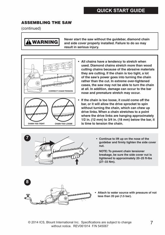
• Allchainshaveatendencytostretchwhenused.Diamondchainsstretchmorethanwoodcuttingchainsbecauseoftheabrasivematerialstheyarecutting.Ifthechainistootight,alotofthesaw’spowergoesintoturningthechainratherthanthecut.Inextremeover-tightenedcases,thesawmaynotbeabletoturnthechainatall.Inaddition,damagecanoccurtothebarnoseandprematurestretchmayoccur.
• Continuetoliftuponthenoseoftheguidebarandfirmlytightenthesidecovernut.
NOTE:Topreventchaintensionerbreakage,besurethesidecovernutistightenedtoapproximately20–25ft-lbs(27–33Nm).
• Attachtowatersourcewithpressureofnotlessthan20psi(1.5bar).
7
8
CHAIN TOO TIGHT CHAIN TOO LOOSE
CORRECT CHAIN TENSION
WARNINGNeverstartthesawwithouttheguidebar,diamondchainandsidecoverproperlyinstalled.Failuretodosomayresultinseriousinjury.
QUICK START GUIDE
• Ifthechainistooloose,itcouldcomeoffthebar,oritwillallowthedrivesprockettospinwithoutturningthechain,whichcanchewupdrivelinks.Whenachainstretchestoapointwherethedrivelinksarehangingapproximately1/2in.(12mm)to3/4in.(18mm)belowthebar,itistimetotensionthechain.

8 © 2014 ICS, Blount International Inc. Specifications are subject to change without notice. REV061914 F/N 545067
QUICK START GUIDE
WARNINGNeverstartthesawwithouttheguidebar,diamondchainandsidecoverproperlyinstalled.Failuretodosomayresultinseriousinjury.
CAUTION
IMPORTANT
Alwaysmovethesawatleast10feet(3m)awayfromthefuelingareabeforestarting.
Placethesawonclearground.Ensurethatsecurefootingisestablishedandchainisnotcontactinganyobjects.
STARTING THE SAW
• Pullthechokeleverout,whichalsosetsthethrottlelock.
• Depressprimerbulbapproximately5–10times.
1
2
ENGINEBREAK-IN
•Itisveryimportanttobreak-inanewengineto“seat”allmovingparts,especiallythepistonrings.
•Tobreak-intheengine,runonefulltankof50:1(2%)fuelatidle,cyclingthethrottleevery5to10minutestopreventloading.
•Failuretobreak-inanenginemayresultinpistonseizure.

9© 2014 ICS, Blount International Inc. Specifications are subject to change without notice. REV061914 F/N 545067
QUICK START GUIDE
• Pushindecompressionvalve.
3
• Openthewatervalve1/4turn.
• Pushchokeleverin.
• Placethesawonstablegroundmakingsurethechainisfreeofanyobstructions.
• Placefootonthebaseoftherearhandle,andplaceonehandonfronthandle.Withoppositehand,slowlypullstarterhandleuntilthestarterpawlsengage.
• Pullthestartercord(hard, fast, short pulls)untilengineinitiallyfiresor“pops”.Couldbeasmanyas10–15pulls.
• Pullthestartercorduntilenginestarts–shouldbe1to2pulls.
• Releasethethrottlelockbymomentarilysqueezingonthethrottletrigger.
• Whentheenginestarts,allowtheenginetoidlebriefly.Squeezethethrottletriggerseveraltimestohelpwarmuptheengine.
• Openthewatervalvecompletely.
4
5
6
7
FIRES
ASMANYAS15PULLS
5TO7PULLS
STARTING THE SAW(continued)
10 © 2014 ICS, Blount International Inc. Specifications are subject to change without notice. REV061914 F/N 545067
THE FOLLOWING SYMBOLS & DEFINITIONS ARE FOUND THROUGHOUT THIS MANUAL AND ARE DESIGNED TO MAKE YOU AWARE OF POTENTIAL HAZARDS OR UNSAFE PRACTICES.
A potentially hazardous situation exists which, if not avoided, could result in death or serious injury.
A potentially hazardous situation exists which, if not avoided, may result in minor or moderate injury or property damage.
A potential situation exists which, if not avoided, may result in product or property damage.
IMPORTANT
WARNING
CAUTION
SYMBOLS & LABELS

11© 2014 ICS, Blount International Inc. Specifications are subject to change without notice. REV061914 F/N 545067
THE FOLLOWING SYMBOLS & LABELS MAY BE FOUND IN THIS MANUAL OR ON THE SAW
Read the operator’s manual carefully and understand the contents before you use this equipment.
Always use: • Protective helmet • Ear protection • Protective glasses or full face protection
Wear hand protection
SYMBOLS & LABELS
12 © 2014 ICS, Blount International Inc. Specifications are subject to change without notice. REV061914 F/N 545067
WARNING
THE FOLLOWING SYMBOL APPLIES TO ALL THE ITEMS LISTED ON THIS PAGE
A potentially hazardous situation exists which, if not avoided, could result in death or serious injury.
Chain breakage can result in high-speed ejection of parts, which can result in death or serious personal injury to operators or bystanders. The items listed below are critical to minimizing the risk of chain breakage and injury.
• DO NOT operate a concrete chain saw with a damaged, modified, broken, or missing side cover, bottom guard, or guard flap. The side cover, bottom guard, and guard flap provides protection against contact with moving parts, ejected debris, broken diamond chain, thrown water and concrete slurry.
• DO NOT operate saw with loose, missing, damaged or improperly repaired parts.
• DO NOT insert saw into a slot narrower than the chain segments. Rapid pushback might occur. Reference: Most diamond segments are .225 inches (5.72 mm) wide.
• DO NOT use damaged, modified or improperly repaired chain.
• DO NOT run saw upside-down. Concrete debris can fly back into the operator’s face.
• DO NOT cut ductile iron pipe with the concrete chain saw (except when using PowerGrit® Utility Saw Chain). Segment loss or diamond chain breakage may occur.
• See page 24 for information about cutting ductile iron pipe with PowerGrit chain.
SAFETY
13© 2014 ICS, Blount International Inc. Specifications are subject to change without notice. REV061914 F/N 545067
SAFETY
CAUTIONA potentially hazardous situation exists which, if not avoided, may result in minor or moderate injury or property damage.
• Always turn a concrete chain saw OFF when performing maintenance on the saw including chain tensioning.
• Never use equipment that is not functioning properly.
• Have the saw repaired only by qualified service personnel.
• Turn engine OFF before refueling. Keep away from open flame. Always provide adequate ventilation when handling fuel. Move saw at least 10 feet (3 m) away from refueling area before starting.
• SealPro® diamond chains require a minimum water pressure of 20 psi (1.5 bar). Insufficient water supply may result in excessive wear to the chain, which can lead to loss of strength and chain breakage, and/or damage to the guidebar nose sprocket.
• Never start saw unless the bar, chain and side cover are properly installed.
THE FOLLOWING SYMBOL APPLIES TO ALL THE ITEMS LISTED ON THIS PAGE

14 © 2014 ICS, Blount International Inc. Specifications are subject to change without notice. REV061914 F/N 545067
SAFETY
GENERAL SAFETY PRECAUTIONS
• Always wear protective clothing, including hard hat, eye protection, hearing protection, and gloves.• Avoid loose fitting clothing. • Perform safety checks before starting each day. • Always operate tool with solid footing and with both hands on saw. • Remove or control slurry to prevent slippery conditions while cutting. • Be sure there are no obstructions (plumbing, electrical conduit, air ducts) and no unnecessary people present. • Set up a well-marked safety zone with a roped boundary and clear signs. • Provide adequate ventilation when working in an enclosed area. Breathing exhaust gases is dangerous. • To avoid electrocution, check for live electrical wiring near cutting area.
ICS diamond chain saws require a continuous water supply to the guidebar and chain, a key purpose of which is dust suppression. The potential for airborne particulates depends on many factors including, but not limited to, the material being cut, application and cutting environment. In all cases, a water flow rate not less than 2 gpm/8 lpm through the saw should be used to minimize this potential. Local and or regional regulations can vary widely. It is the responsibility of the operator to wear appropriate dust protection applicable in their area and suitable to the application.

15© 2014 ICS, Blount International Inc. Specifications are subject to change without notice. REV061914 F/N 545067
SAFETY
IMPORTANT
THE FOLLOWING SYMBOL APPLIES TO ALL ITEMS LISTED ON THIS PAGE
Note: The concrete chain saw is equipped with a 2-stroke engine and must always be run using a mixture of gasoline and ICS® 2-stroke engine oil, or other high quality 2-stroke oil that has been formulated for air cooled power equipment. It is important to accurately measure the amount of oil to be mixed to ensure that correct mixture is obtained. When mixing small amounts of fuel, even small inaccuracies can drastically affect the ratio of the mixture.
ENGINE BREAK-IN
• It is very important to break-in a new engine to “seat” all moving parts, especially the piston rings.
• To break-in the engine, run one full tank of 50:1 (2%) fuel at idle, cycling the throttle every 5 to 10 minutes to prevent loading.
• Failure to break-in an engine may result in piston seizure.
• This engine is designed to be operated on premium unleaded gasoline.
• Use high quality, unleaded gasoline with a minimum octane rating of 90. If lower octane gasoline is used, engine temperature will increase which can result in a piston seizure and damage to the engine.
• Fuel mixture: 50:1 (2%) gasoline/oil mixture. Incorrect fuel mixture is the number one cause of piston seizure.
• Use ICS® brand 2-stroke engine oil, or other high quality 2-stroke oil that has been formulated for air cooled power equipment.
• Never use two-stroke oil formulated for water-cooled two-cycle engines, such as outboard motor oil.
• Never use motor oil intended for four-stroke engines.

16 © 2014 ICS, Blount International Inc. Specifications are subject to change without notice. REV061914 F/N 545067
Engine Type 2-stroke, Air Cooled
Displacement 5.7 cu-in (94 cc)
Horsepower 6.4 hp (4.8 kW) @ 9000 rpm
Torque 50.4 in-lbs (5.7 Nm) @ 7,200 rpm
Engine Speed 9,300 +/- 150 rpm (max)2,700 +/- 100 rpm (idle)
Weight 21 lbs (9.5 kg) powerhead only
Dimensions18 in (46 cm) length14 in (36 cm) height12 in (30 cm) width
Air Filter Water resistant polyester
Carburetor Walbro RWJ-5A
Starter Dust and water resistant
Ignition Special water resistant electronic ignition
Clutch Centrifugal, three shoe, three spring
Fuel ratio 50:1 (2%) gasoline-to-oil
Fuel Capacity 0.26 gallon (1 liter)
Water Supply Minimum 20 psi (1.5 bar)
Water Flow Minimum: 2 gpm (8 lpm)
Noise Level 112 dB(A) at 3 ft (1 m)
Vibration Level 3.9 m/s2 (front handle) 4.1 m/s2 (rear handle)
Engine Break-in Period One tank, without cutting, cycling throttle
Spark Plug NGK BPMR7A or Champion RCJ6Y Electrode gap 0.020 in (0.5 mm)
TECHNICAL SPECIFICATIONS

17© 2014 ICS, Blount International Inc. Specifications are subject to change without notice. REV061914 F/N 545067
SETUP
STEP 1Loosen side cover nut and remove side cover.
GUIDEBAR AND DIAMOND CHAIN INSTALLATION
STEP 2Place bar onto stud and engage alignment block.

18 © 2014 ICS, Blount International Inc. Specifications are subject to change without notice. REV061914 F/N 545067
GUIDEBAR AND DIAMOND CHAIN INSTALLATION
STEP 3Mount the diamond chain on the guidebar starting at the drive sprocket and continue over the guidebar nose. NOTE: FORCE4 requires rim to be pulled outward for chain installation.
STEP 4Install the side cover and ensure chain adjustment pin engages hole in bar. Do not fully tighten side cover nut until after chain is properly tensioned.
SETUP

19© 2014 ICS, Blount International Inc. Specifications are subject to change without notice. REV061914 F/N 545067
SETUP
STEP 6Before cutting, check for proper tension by pulling the chain around the bar by hand. If you cannot easily pull by hand, the chain is too tight and needs to be loosened slightly. CAUTION: Be aware that the guidebar rails may develop sharp edges over time so always pull the diamond chain by the diamond segments.
STEP 5Make sure all the drive links are inside the guidebar groove then lift the bar nose and tension the chain by turning the screw clockwise.
GUIDEBAR AND DIAMOND CHAIN INSTALLATION
20 © 2014 ICS, Blount International Inc. Specifications are subject to change without notice. REV061914 F/N 545067
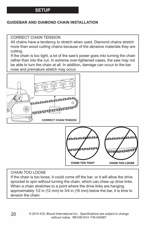
CORRECT CHAIN TENSIONAll chains have a tendency to stretch when used. Diamond chains stretch more than wood cutting chains because of the abrasive materials they are cutting. If the chain is too tight, a lot of the saw's power goes into turning the chain rather than into the cut. In extreme over-tightened cases, the saw may not be able to turn the chain at all. In addition, damage can occur to the bar nose and premature stretch may occur.
CHAIN TOO LOOSEIf the chain is too loose, it could come off the bar, or it will allow the drive sprocket to spin without turning the chain, which can chew up drive links. When a chain stretches to a point where the drive links are hanging approximately 1/2 in (12 mm) to 3/4 in (18 mm) below the bar, it is time to tension the chain.
CORRECT CHAIN TENSION
CHAIN TOO TIGHT CHAIN TOO LOOSE
GUIDEBAR AND DIAMOND CHAIN INSTALLATION
SETUP

21© 2014 ICS, Blount International Inc. Specifications are subject to change without notice. REV061914 F/N 545067
GUIDEBAR AND DIAMOND CHAIN INSTALLATION
SETUP
STEP 7Continue to lift up on the nose of the guidebar and firmly tighten the side cover nut.NOTE: To prevent chain tensioner breakage, be sure the side cover nut is tightened to approximately 20-25 ft-lbs (27-33 Nm).
STEP 8Attach to water source with pressure of not less than 20 psi (1.5 bar).

22 © 2014 ICS, Blount International Inc. Specifications are subject to change without notice. REV061914 F/N 545067
CAUTION
FUEL HANDLING
FUEL MIXTURE: 50:1 (2%) gasoline/oil mixture.
GASOLINE OIL
USGallon
USFl oz
1 2.6 2 1/2 6.4
5 12.8
GASOLINE OIL
Liters ml 1 20 5 100 10 200 20 400
• Use premium unleaded gasoline with a minimum octane rating of 90. If lower octane gasoline is used, engine temperature will increase which can result in a piston seizure and damage to the engine.
• Always provide adequate ventilation when handling fuel.
• Use caution when handling gasoline. Avoid direct contact with skin or inhaling fuel vapor.
OPERATION
23© 2014 ICS, Blount International Inc. Specifications are subject to change without notice. REV061914 F/N 545067
FUEL MIXTURE: 50:1 (2%) gasoline/oil mixture.
FUEL MIXING
• Always mix gasoline and oil in a clean container intended for use with fuel.
• Keep fuel container closed tightly to prevent moisture from getting into the fuel.
• Always begin mixing fuel by adding half the amount of gasoline to be used. Then add the correct amount of 2-stroke oil for 50:1 (2%) mixture and finish filling the container with gasoline.
• Do not mix more than one month’s supply of fuel. This helps prevent the separation of the 2-stroke oil from the gasoline (varnishing).
• If the saw is not used for an extended period of time (3 months) the fuel tank should be emptied and cleaned.
FUELING
• Always shut off the saw before fueling.
• Before fueling, clean the area around fuel cap to prevent dirt from contaminating the fuel. Contamination of the fuel tank can lead to saw malfunction.
• Thoroughly mix the fuel in it’s container before fueling.
• Slowly open the fuel cap to release any pressure that may have built-up in the tank.
• After adding fuel, carefully install the fuel cap and tighten firmly by hand.
OPERATION
24 © 2014 ICS, Blount International Inc. Specifications are subject to change without notice. REV061914 F/N 545067
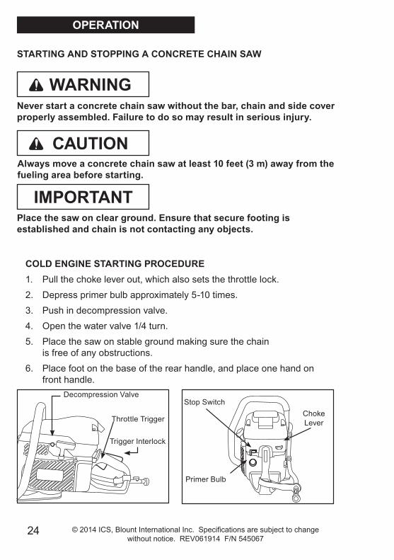
COLD ENGINE STARTING PROCEDURE 1. Pull the choke lever out, which also sets the throttle lock. 2. Depress primer bulb approximately 5-10 times. 3. Push in decompression valve. 4. Open the water valve 1/4 turn. 5. Place the saw on stable ground making sure the chain
is free of any obstructions. 6. Place foot on the base of the rear handle, and place one hand on
front handle.
CAUTION
STARTING AND STOPPING A CONCRETE CHAIN SAW
Never start a concrete chain saw without the bar, chain and side cover properly assembled. Failure to do so may result in serious injury.
Always move a concrete chain saw at least 10 feet (3 m) away from the fueling area before starting.
Place the saw on clear ground. Ensure that secure footing is established and chain is not contacting any objects.
IMPORTANT
WARNING
Throttle Trigger
Trigger Interlock
Decompression ValveStop Switch
Primer Bulb
Choke Lever
OPERATION

25© 2014 ICS, Blount International Inc. Specifications are subject to change without notice. REV061914 F/N 545067
WARM ENGINE STARTING PROCEDURE 1. Use the same procedure as starting a cold engine, but pull choke lever
out, and then push back in to set the throttle lock. If choke is used on a warm engine, the carburetor will flood with gas.
2. If the engine does not start in 3 hard, fast pulls with the throttle locked, fully squeeze and hold the trigger while pulling the starter cord 3 more times.
Note: To hold the trigger fully open it may be necessary to insert right foot into rear handle opening and twist.
STOPPING THE SAW• To turn the engine off, push stop switch to the "STOP" position. Close
water valve.
COLD ENGINE STARTING PROCEDURE, CONT. 7. With opposite hand, slowly pull starter handle until the
starter pawls engage. 8. Pull the starter cord (hard, fast, short pulls) until engine initially fires
or "pops". Could be as many as 10-15 pulls. 9. Push the choke lever in. 10. Pull the starter cord until engine starts - should be 1 to 2 pulls. 11. Release the throttle lock by momentarily squeezing on the throttle
trigger.12. When the engine starts, allow the engine to idle briefly.
Squeeze the throttle trigger several times to help warm up the engine.
13. Open the water valve completely.
OPERATION

26 © 2014 ICS, Blount International Inc. Specifications are subject to change without notice. REV061914 F/N 545067
PRE-CUT CHECKLIST
• Ensure proper chain tension: The chain should be easily pulled around the guidebar by hand.
• Ensure all safety devices are properly mounted and functional and that all controls are in proper working order.
• Be sure there are no obstructions (plumbing, electrical conduit, air ducts) and no unnecessary people present.
• Always wear protective clothing, including hard hat, eye protection, hearing protection, non-slip safety boots, and gloves. Avoid wearing loose fitting clothing.
• Adequate Water Supply and Pressure: Minimum Flow: 2 gpm (8 lpm) Minimum Water Pressure: 20 psi (1.5 bar)
• Diamond chains with SealPro® require a minimum water pressure of 20 psi (1.5 bar).
The single most important factor an operator can control to increase chain life is to use adequate water pressure. Insufficient water supply will result in excessive wear to the chain, which can lead to loss of strength and chain breakage, and/or damage to the guidebar nose sprocket.
IMPORTANT
OPERATION
27© 2014 ICS, Blount International Inc. Specifications are subject to change without notice. REV061914 F/N 545067
PLANNING THE CUT
• Select the proper chain type for the material being cut.
• Outline the cut with a permanent marker for a visual cutting guide.
• Avoid pinching the guidebar and chain. Always cut the bottom of an opening first, then top, and then the sides. Save the easiest cut for last.
• For the straightest cuts use the “Step Cut” method. First score the entire cut line approximately a half-inch deep using the nose of the bar. Next, deepen the cut by about two inches. Then plunge all the way through and complete the cut using the WallWalker®.
• Be sure cut concrete cannot fall and injure operator or bystanders. Concrete is very heavy, one cubic foot = 12 in x 12 in x 12 in = 150 lbs (30 cm x 30 cm x 30 cm = 68 kg).
• Check for and remove any obstructions (plumbing, electrical conduit, air ducts, etc,) that may interfere with the cut.
OPERATION

28 © 2014 ICS, Blount International Inc. Specifications are subject to change without notice. REV061914 F/N 545067
CUTTING WITH THE 695GC
To start a cut, hold trigger on full throttle and slowly plunge the nose of the bar straight into the wall. Lengthen the cut and engage the point of the WallWalker®. Use the WallWalker as a pivot point and pull up on the rear handle to rotate the bar into the cut.
CUTTING TIPS
• Always operate the concrete chain saw at full throttle. If too much force is applied, the saw will lug or stall. The chain will not have enough speed to cut effectively. If too little feed force is applied, the diamonds will skid and glaze over.
• For straighter cuts use the “Step Cut” method. First score the entire cut line with the nose of the guidebar approximately 1/2 in (12 mm) to 1 in (25 mm) deep. Next, deepen the cut by about 2 in (50 mm). This groove will help guide the guidebar for a straight cut. Then plunge all the way through and complete the cut using the WallWalker.
• Plunge cut instead of starting at the top surface of the wall. This will reduce chatter, extend diamond life, create a straighter cut and more quickly enable the use of the WallWalker.
OPERATION
29© 2014 ICS, Blount International Inc. Specifications are subject to change without notice. REV061914 F/N 545067
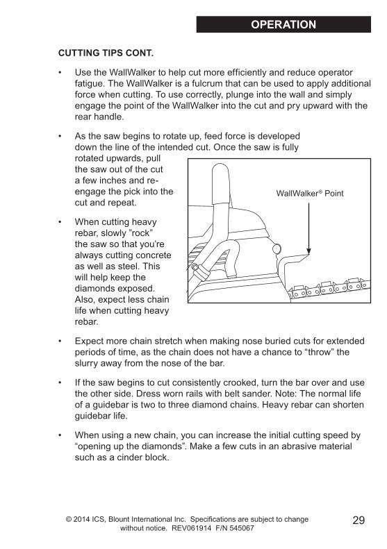
WallWalker® Point
OPERATION
CUTTING TIPS CONT.
• Use the WallWalker to help cut more efficiently and reduce operator fatigue. The WallWalker is a fulcrum that can be used to apply additional force when cutting. To use correctly, plunge into the wall and simply engage the point of the WallWalker into the cut and pry upward with the rear handle.
• As the saw begins to rotate up, feed force is developed down the line of the intended cut. Once the saw is fully rotated upwards, pull the saw out of the cut a few inches and re-engage the pick into the cut and repeat.
• When cutting heavy rebar, slowly ”rock” the saw so that you’re always cutting concrete as well as steel. This will help keep the diamonds exposed. Also, expect less chain life when cutting heavy rebar.
• Expect more chain stretch when making nose buried cuts for extended periods of time, as the chain does not have a chance to “throw” the slurry away from the nose of the bar.
• If the saw begins to cut consistently crooked, turn the bar over and use the other side. Dress worn rails with belt sander. Note: The normal life of a guidebar is two to three diamond chains. Heavy rebar can shorten guidebar life.
• When using a new chain, you can increase the initial cutting speed by “opening up the diamonds”. Make a few cuts in an abrasive material such as a cinder block.

30 © 2014 ICS, Blount International Inc. Specifications are subject to change without notice. REV061914 F/N 545067
SYSTEM CLEAN-UP
• After cutting, run the saw for at least 15 seconds with the water on to flush slurry and debris from chain, bar and drive sprocket.
• Wash concrete slurry from saw assembly.
• Avoid getting any water in the carburetor or exhaust system. If water enters exhaust port, point the bar tip down and pull the starter handle several times to expel water from muffler.
• Remove bar and chain. Flush out the chain tensioner and side cover with water. Lubricate tensioner with grease.
• After cleaning the saw, spray the entire saw body, chain, bar, and drive sprocket with lightweight oil. Using lightweight oil on the saw will minimize rust and help reduce slurry build up.
CUTTING DUCTILE IRON PIPE WITH THE POWERGRIT® UTILITY SAW CHAIN
NEVER cut ductile iron pipe with the saw unless using PowerGrit Utility Saw Chain. The following are safety precautions that should always be followed when using PowerGrit.
• Before cutting, make sure the pipe is in a safe condition to be cut. Support the work piece in such a way that the cut remains open during the cutting operation and when the cut is finished. Pinching the chain during the cut could cause chain breakage and could result in death or serious injury to the operator.
WARNING
OPERATION
31© 2014 ICS, Blount International Inc. Specifications are subject to change without notice. REV061914 F/N 545067
Follow these simple maintenance guidelinesand your saw will continue running at its very best.
AFTER EACH USE1. Rinse the saw, guidebar and diamond chain with water.
2. Inspect and tighten all fasteners as necessary.
3. Inspect, flush and grease the chain tensioner.
4. Inspect drive sprocket for wear. Replace if tooth tips are pointed, or if groove cuts through top of tooth.
5. Check clutch cup needle bearing for wear. Ensure clutch cup spins freely and without excessive play.
6. Check starter cord for wear or damage. Replace as necessary.
7. Inspect air filter. Replace filter if dirty.
8. Spray saw, guidebar, and chain with lightweight oil.
9. Spray lightweight oil into the air intake slots on the starter housing to keep starter pawls from sticking.
AFTER 10 HOURS OF USE1. Remove the starter cover and clean the flywheel fins and the starter
pawls with a wire brush, then grease the starter pawls.
2. Remove the spark plug and clean with a wire brush. Check the electrode gap. The correct gap is 0.020 inches (0.5 mm).
3. Grease the clutch cup needle bearing,
AFTER 40 HOURS OF USE1. Change the spark plug. Adjust the electrode to 0.020 in (0.5 mm).
2. Check the fuel filter located inside the fuel tank. Clean or replace if clogged.
MAINTENANCE

32 © 2014 ICS, Blount International Inc. Specifications are subject to change without notice. REV061914 F/N 545067
AIR FILTER
The polyester air filter must be kept clean for the engine to operate properly. If the saw is not reaching full RPM, most likely the air filter is dirty.
IMPORTANT
• The air filter should be free of holes and white in color.
• Replace air filter when dirty.
• When replacing the air filter, clean the area inside the air intake housing with a clean rag prior to installing new filter.
MAINTENANCE
33© 2014 ICS, Blount International Inc. Specifications are subject to change without notice. REV061914 F/N 545067
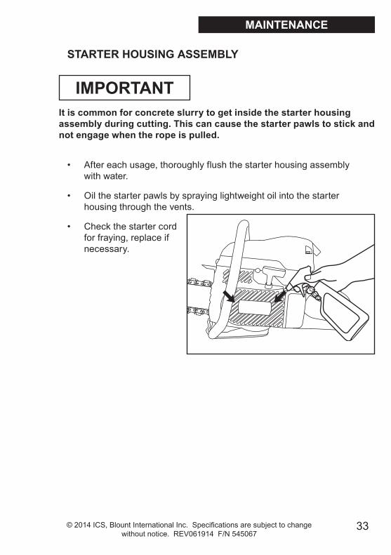
STARTER HOUSING ASSEMBLY
It is common for concrete slurry to get inside the starter housing assembly during cutting. This can cause the starter pawls to stick and not engage when the rope is pulled.
IMPORTANT
• After each usage, thoroughly flush the starter housing assembly with water.
• Oil the starter pawls by spraying lightweight oil into the starter housing through the vents.
• Check the starter cord for fraying, replace if necessary.
MAINTENANCE
34 © 2014 ICS, Blount International Inc. Specifications are subject to change without notice. REV061914 F/N 545067
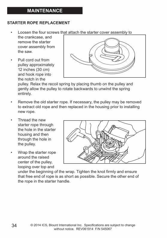
STARTER ROPE REPLACEMENT
• Loosen the four screws that attach the starter cover assembly to the crankcase, and remove the starter cover assembly from the saw.
• Pull cord out from pulley approximately 12 inches (30 cm) and hook rope into the notch in the pulley. Relax the recoil spring by placing thumb on the pulley and gently allow the pulley to rotate backwards to unwind the spring entirely.
• Remove the old starter rope. If necessary, the pulley may be removed to extract old rope and then replaced in the housing prior to installing new rope.
• Thread the new starter rope through the hole in the starter housing and then through the hole in the pulley.
• Wrap the starter rope around the raised center of the pulley, looping over top and under the beginning of the wrap. Tighten the knot firmly and ensure that free end of rope is as short as possible. Secure the other end of the rope in the starter handle.
MAINTENANCE

35© 2014 ICS, Blount International Inc. Specifications are subject to change without notice. REV061914 F/N 545067
TENSIONING THE RECOIL SPRING
• Hook the rope in the notch of pulley and wind the rope clockwise three times around the raised center of the pulley.
• Pull the starter rope with the handle until the rope is unwound, tensioning the spring. Repeat this process, but this time, wind the rope clockwise four times around and then pull the rope with the handle to complete the tensioning of the spring.
NOTE: When released, the starter handle should be drawn to the correct start position after tensioning the spring.
CAUTION: Check that the pulley can be turned an additional 1/2 turn when the starter cord is pulled all the way out.
MAINTENANCE
STARTER HOUSING ASSEMBLY
• To reattach the starter cover assembly, first pull the starter cord out, then hold the starter housing against the crankcase. Slowly release the starter cord to enable the pulley to fit between the pawls.
• Insert and tighten the screws. Use blue Loctite® #242.

36 © 2014 ICS, Blount International Inc. Specifications are subject to change without notice. REV061914 F/N 545067
CHAIN TENSIONER
The chain tensioner can become clogged with concrete slurry during cutting. After each use thoroughly flush the chain tensioner with water and apply a liberal amount of grease.
IMPORTANT
NOTE: The chain tensioner is located on side cover, to the outside of the guidebar.
Most Common Causes of Tensioner Damage:
• Side cover nut is not tight enough. Side cover nut should be torqued to 20-25 ft-lbs (27-33 Nm).
• Chain tensioning is attempted without loosening the side cover nut.
• Concrete debris in tensioner pocket.
Chain Tensioner
Chain Tensioner
MAINTENANCE

37© 2014 ICS, Blount International Inc. Specifications are subject to change without notice. REV061914 F/N 545067
MAINTENANCE
DRIVE SPROCKET
The drive sprocket (rim sprocket) is a wear item and should be replaced every two to three diamond chains, or when drive teeth become pointed.
IMPORTANT
The needle bearing inside the splined adapter should be greased regularly and should be replaced with each new clutch cup.
A rim sprocket system consists of a clutch cup w/ splined adapter and a rim sprocket. When the rim sprocket wears out, it is the only part that needs to be replaced. The clutch cup with splined adapter is a wear item that needs replacement after 3 to 5 rim sprockets have been used.
• Inspect the rim sprocket for wear. Replace the rim sprocket if the drive teeth become pointed.
• Check the needle bearing inside the splined adapter by spinning clutch cup. Ensure clutch cup spins freely and without excessive play.
• The needle bearing must be greased regularly, use high quality water-resistant bearing grease.
DRIVE SPROCKET REMOVAL
• Remove the side cover, guidebar and diamond chain.
• Using a screwdriver, carefully pry the spring clip from the half collars. TIP: Cup your hand over the end of shaft to prevent the spring clip from being ejected. CAUTION: Wear safety glasses.
• Remove the half collars and retaining washer from the shaft.
• Slide the drive sprocket off of the splined adapter.
Clutch Cup
Splined Adaper
Drive Sprocket
Retaining Washer
Half Collar
Spring Clip

38 © 2014 ICS, Blount International Inc. Specifications are subject to change without notice. REV061914 F/N 545067
MAINTENANCE
DRIVE SPROCKET INSTALLATION
• Prior to installing a new drive sprocket, slide the clutch cup off of the shaft and apply high quality water-resistant grease to the needle bearing.
• Reengage the clutch cup onto the shaft and slide the drive sprocket onto the spline adapter, either side out.
• Install the retaining washer and half collars onto the shaft.
• Place the spring clip atop the half collars, ensuring the half collars are symmentrical with equal gap on either side.
• Engage the spring clip onto the half collars by firmly pressing down with a screwdriver over top one of the gaps. TIP: Hold your thumb on the spring clip over the opposite side gap to maintain placement.
• Once the spring clip is partially engaged on one side, perform the same technique to the other side, again pressing firmly over top of the gap.
• Check proper spring clip engagement by carefully prying out on the half collars. Both half collars should be firmly secured to the shaft.
Clutch Cup
Splined Adaper
Drive Sprocket
Retaining Washer
Half Collar
Spring Clip
Grease needle bearing

39© 2014 ICS, Blount International Inc. Specifications are subject to change without notice. REV061914 F/N 545067
SPARK PLUG
• A worn or fouled spark plug can cause a loss of power, difficulty starting or rough idle.
• If the spark plug is dirty, clean it with a wire brush and check the electrode gap. Readjust if necessary. The correct gap is .020 in (0.5 mm).
• The spark plug should be replaced after 40 hours of operation or earlier if the electrode is badly corroded.
• Always use the recommended spark plug type. Using the wrong spark plug can severely damage the piston and cylinder (NGK #BPMR7A or Champion RCJ6Y).
MAINTENANCE
CARBURETOR
• The function of the carburetor is to mix fuel with air. Adjustments other than idle speed should only be made by a servicing dealer.
• Before adjusting the engine idle speed, make sure the air filter is clean and the engine is warmed up.
Idle Screw is adjusted so that the engine idles smoothly but the clutch does not engage.
• If saw has been running satisfactorily and there is a gradual decrease in power and drop in RPM at full throttle, the filter may have become dirty or saturated with water.
Carburetor idle screw

40 © 2014 ICS, Blount International Inc. Specifications are subject to change without notice. REV061914 F/N 545067
GUIDEBARS
• The bar is designed to be used on both sides. If the cut is consistently leading to one side, turn the bar over to expose a new set of rails.
• A table mounted belt or disc sander can be used to square the rails of a worn bar. A badly worn bar can quickly damage an expensive chain. If the chain is touching the bottom of the bar groove, replace the bar.
• Check the guidebar for straightness.
• Proper chain tension will extend bar life. .
• Under some circumstances, especially low water pressure, the sprocket nose can wear out before the guidebar body. Sprocket nose replacement kits may be purchased from an Authorized Dealer.
• Spray the chain and bar with lightweight oil for storage.
• Store bar with the sprocket nose up.
• Periodically clean the water ports inside the groove of the bar using a small diameter piece of wire.
• The bar is solely a guide track for the chain. Never use the bar to lift, twist or pry concrete material.
MAINTENANCE
41© 2014 ICS, Blount International Inc. Specifications are subject to change without notice. REV061914 F/N 545067
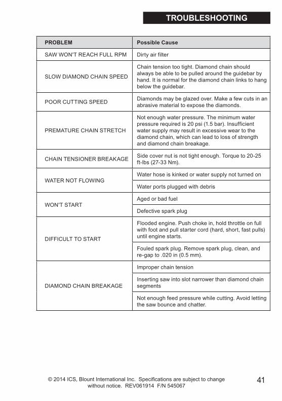
PROBLEM Possible Cause
SAW WON'T REACH FULL RPM Dirty air filter
SLOW DIAMOND CHAIN SPEED
Chain tension too tight. Diamond chain should always be able to be pulled around the guidebar by hand. It is normal for the diamond chain links to hang below the guidebar.
POOR CUTTING SPEED Diamonds may be glazed over. Make a few cuts in an abrasive material to expose the diamonds.
PREMATURE CHAIN STRETCH
Not enough water pressure. The minimum water pressure required is 20 psi (1.5 bar). Insufficient water supply may result in excessive wear to the diamond chain, which can lead to loss of strength and diamond chain breakage.
CHAIN TENSIONER BREAKAGE Side cover nut is not tight enough. Torque to 20-25 ft-lbs (27-33 Nm).
WATER NOT FLOWINGWater hose is kinked or water supply not turned on
Water ports plugged with debris
WON'T STARTAged or bad fuel
Defective spark plug
DIFFICULT TO START
Flooded engine. Push choke in, hold throttle on full with foot and pull starter cord (hard, short, fast pulls) until engine starts.
Fouled spark plug. Remove spark plug, clean, and re-gap to .020 in (0.5 mm).
DIAMOND CHAIN BREAKAGE
Improper chain tension
Inserting saw into slot narrower than diamond chain segments
Not enough feed pressure while cutting. Avoid letting the saw bounce and chatter.
TROUBLESHOOTING

42 © 2014 ICS, Blount International Inc. Specifications are subject to change without notice. REV061914 F/N 545067
APPROXIMATE CUTTING RATES
Material Cutting Rate
Hard aggregate & Steel 15-25 sq-in/min (90-160 sq-cm/min) Medium aggregates 20-30 sq-in/min (160-190 sq-cm/min) Masonry, Soft aggregates 30-50 sq-in/min (190-320 sq-cm/min)
INCH-FOOT DEFINITION
An in-ft is a measure of how much material is to be cut. An in-ft is defined as: depth in inches times length in feet. Note: 129 in-ft = 1m2
Example: How many in-ft are in this doorway?
1. Determine the depth of the cut in inches. For this example, 8 inches.
2. Determine the length of the cut in feet. 3 + 7 + 3 + 7 = 20 feet
3. Multiply the two numbers 8 in x 20 ft = 160 in-ft
REFERENCE

43© 2014 ICS, Blount International Inc. Specifications are subject to change without notice. REV061914 F/N 545067
EMISSIONS
YOUR WARRANTY RIGHTS AND OBLIGATIONSThe U.S. Environmental Protection Agency (EPA), Environment Canada and ICS, Blount Inc. are pleased to explain the Emissions Control System Warranty on your 2009 and later small non-road engine. In the U.S. and Canada, new small non-road engines must be designed, built and equipped to meet federal emission regulations.
ICS must warrant the emission control system on your small non-road engine for the period of time listed below provided there has been no abuse, neglect or improper maintenance of your unit.
Your emission control system includes parts such as the carburetor and the ignition system. Also included may be hoses, connectors and other emission related assemblies.
Where a warrantable condition exists, ICS will repair your small non-road engine at no cost to you. Expenses covered under warranty include diagnosis, parts and labor.
MANUFACTURER’S WARRANTY COVERAGEThe emission control system on 2009 and later small non-road engines is warranted for two years. If any emission related part on your engine (as listed above) is defective, the part will be repaired or replaced by ICS.
continued on page 43
FEDERAL EMISSION CONTROL WARRANTY STATEMENT

44 © 2014 ICS, Blount International Inc. Specifications are subject to change without notice. REV061914 F/N 545067
EMISSIONS
FEDERAL EMISSION CONTROL WARRANTY STATEMENT, CONT.
OWNER′S WARRANTY RESPONSIBILITIESAs the small non-road engine owner, you are responsible for the performance of the required maintenance listed in your Operator′s Manual. ICS recommends that you retain all receipts covering maintenance on your small non-road engine, but ICS cannot deny warranty solely for the lack of receipts or for your failure to ensure the performance of all scheduled maintenance. However, ICS reserves the right to deny warranty coverage if your small non-road engine, or a part of it, has failed due to abuse, neglect, improper maintenance, unapproved modifications or the use of parts not made or approved by the original equipment manufacturer.
You are responsible for presenting your small non-road engine to an ICS authorized servicing dealer as soon as a problem exists. The warranty repairs should be completed in a reasonable amount of time, typically not to exceed 30 days.
If you have any questions regarding your warranty rights and responsibilities, please contact an ICS customer service representative at 1.800.321.1240 or at [email protected]
www.icsbestway.com
LENGTH OF COVERAGEICS warrants to the initial purchaser and each subsequent owner that the engine is free from defects in materials and workmanship which cause the non-road engine to fail to conform with applicable emission regulations for a period of two years.
WARRANTY PERIODThe warranty period begins on the date of sale of the small non-road engine to the initial purchaser.

45© 2014 ICS, Blount International Inc. Specifications are subject to change without notice. REV061914 F/N 545067
I C S | B L O U N T , E U R O P E S A . | R u e E m i l e F r a n c q u i 5 | 1 4 3 5 M o n t - S i a n t - G u i b e r t , B e l g i u m
EECC DDEECCLLAARRAATTIIOONN OOFF CCOONNFFOORRMMIITTYY Manufacturer: BLOUNT INC. DECLARES THE FOLLOWING PRODUCT(S) COMPLY WITH ALL RELEVANT EUROPEAN DIRECTIVES Machinery: ICS 695GC/695F4 Gas Saw EUROPEAN DIRECTIVES AND STANDARDS
CLARIFICATION OF PRODUCT CLASS: The ICS 695GC/695F4 Gas Saw, using the appropriate genuine ICS Diamond Chain, is designed to ONLY cut concrete or designated materials other than wood. The cutting means is by grinding through the work-piece, using a continuous water supply as a coolant and lubricant. This product is not intended for use with conventional wood cutting saw chain. By design, this product is not intended to comply with the definition of a chain -saw as described by ISO 6531 – “Machinery for Forestry – Portable hand-held chain-saws – Vocabulary”:
ISO6531-1999; Clause 2.2.1; chain-saw: “power driven tool designed to cut wood with a saw chain and consisting of an integrated compact unit of handles, power source, and cutting attachment, designed to be supported with two hands”
Corporate Contact: European File Location:
John DeHaven Manager – Product Safety & Compliance Blount International Inc. Phone: 001.503.653.4273 Fax: 001.503.653.4701
Place: Portland Oregon, USA Date: 16 December 2013
Machinery Directive 2006/42/EC:2006
Safety of machinery - Basic concepts, general principles for design; Basic terminology and methodology EN ISO 12100-1:2003
Building construction machinery and equipment - portable, hand-held, internal combustion engine driven cut-off machines - safety requirements EN ISO 19432:2006
Electromagnetic compatibility 2004/108/EC and CISPR12 2007
Noise Emissions 2000/14/EC
Portable, hand-held, internal combustion cutting-off machines - safety EN 1454:1997
Blount Europe S.A. Rue Emile Francqui, 5 1435 Mont-Saint-Guibert Belgium
Blount International, Inc. 4909 SE International Way Portland, Oregon 97222 USA Phone: 001.800.321.1240
DECLARATION OF CONFORMITY
46 © 2014 ICS, Blount International Inc. Specifications are subject to change without notice. REV061914 F/N 545067
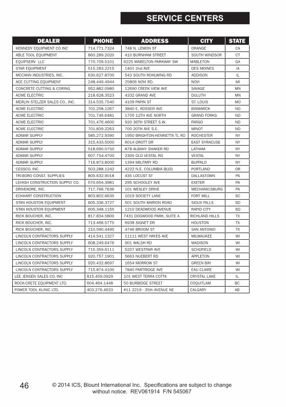
SERVICE CENTERS
DEALER PHONE ADDRESS CITY STATE KENNEDY EQUIPMENT CO INC 714.771.7324 748 N. LEMON ST ORANGE CA
ABLE TOOL EQUIPMENT 860.289.2020 410 BURNHAM STREET SOUTH WINDSOR CT
EQUIPSERV LLC 770.709.5101 6225 MABELTON PARKWAY SW MABLETON GA
STAR EQUIPMENT 515.283.2215 1401 2nd AVE DES MOINES IA
MCCANN INDUSTRIES, INC. 630.627.8700 543 SOUTH ROHLWING RD ADDISON IL
ACE CUTTING EQUIPMENT 248.449.4944 25806 NOVI RD. NOVI MI
CONCRETE CUTTING & CORING 952.882.0980 12690 CREEK VIEW AVE SAVAGE MN
ACME ELECTRIC 218.628.3523 4332 GRAND AVE DULUTH MN
MERLIN STELZER SALES CO., INC. 314.535.7540 4109 PAPIN ST ST. LOUIS MO
ACME ELECTRIC 701.258.1267 3840 E. ROSSER AVE BISMARCK ND
ACME ELECTRIC 701.746.6481 1705 12TH AVE NORTH GRAND FORKS ND
ACME ELECTRIC 701.476.4600 920 36TH STREET S.W. FARGO ND
ACME ELECTRIC 701.839.2263 700 20TH AVE S.E. MINOT ND
ADMAR SUPPLY 585.272.9390 1950 BRIGHTON-HENRIETTA TL RD ROCHESTER NY
ADMAR SUPPLY 315.433.5000 6014 DROTT DR EAST SYRACUSE NY
ADMAR SUPPLY 518.690.0750 878 ALBANY SHAKER RD LATHAM NY
ADMAR SUPPLY 607.754.4700 2305 OLD VESTAL RD VESTAL NY
ADMAR SUPPLY 716.873.8000 1394 MILITARY RD BUFFALO NY
CESSCO, INC. 503.288.1242 4222 N.E. COLUMBIA BLVD. PORTLAND OR
TRI-BORO CONST. SUPPLIES 800.632.9018 435 LOCUST ST DALLASTOWN PA
LEHIGH CONSTRUCTION SUPPLY CO. 570.654.3981 295 SCHOOLEY AVE EXETER PA
DRIVEKORE, INC. 717.766.7636 101 WESLEY DRIVE MECHANICSBURG PA
ECKHART CONSTRUCTION 803.802.6635 1019 SOCIETY LANE FORT MILL SC
STAN HOUSTON EQUIPMENT 605.336.3727 501 SOUTH MARION ROAD SIOUX FALLS SD
STAN HOUSTON EQUIPMENT 605.348.1155 1210 DEADWOOD AVENUE RAPID CITY SD
RICK BOUCHER, INC. 817.834.5800 7431 DOGWOOD PARK, SUITE A RICHLAND HILLS TX
RICK BOUCHER, INC. 713.466.5775 6938 SIGNET DR HOUSTON TX
RICK BOUCHER, INC. 210.590.4495 4746 BROOM ST SAN ANTONIO TX
LINCOLN CONTRACTORS SUPPLY 414.541.1327 11111 WEST HAYES AVE MILWAUKEE WI
LINCOLN CONTRACTORS SUPPLY 608.249.6476 901 WALSH RD MADISON WI
LINCOLN CONTRACTORS SUPPLY 715.359.6111 5207 WESTFAIR AVE SCHOFIELD WI
LINCOLN CONTRACTORS SUPPLY 920.757.1901 5663 NUEBERT RD APPLETON WI
LINCOLN CONTRACTORS SUPPLY 920.432.8697 1654 MORROW ST GREEN BAY WI
LINCOLN CONTRACTORS SUPPLY 715.874.4100 7840 PARTRIDGE AVE EAU CLAIRE WI
LEE JENSEN SALES CO, INC 815.459.0929 101 WEST TERRA COTTA CRYSTAL LAKE IL
ROCK-CRETE EQUIPMENT LTD. 604.464.1448 50 BURBIDGE STREET COQUITLAM BC
POWER TOOL KLINIC LTD. 403.276.4633 #11 2219 - 35th AVENUE NE CALGARY AB

47© 2014 ICS, Blount International Inc. Specifications are subject to change without notice. REV061914 F/N 545067

48 © 2014 ICS, Blount International Inc. Specifications are subject to change without notice. REV061914 F/N 545067
ICS, Blount Inc.4909 SE International Way
Portland, OR 97222Tel 800-321-1240 Fax 503-653-4393
icsbestway.com
695GC / 695F4 OPERATOR MANUAL