Embed Size (px)
Citation preview

1
69/12KV SUBSTATION DESIGN
ISU SENIOR DESIGN GROUP: MAY 15-01
Matt Backes Team Leader
Faran Malik Communication Leader
Ryan Jerve Communication Leader
Bhargav Gouni Key Concept Holder
Kiran Rane Key Concept Holder
Sohail Suryavanshi Webmaster
Project Website: http://ecemay15-01.weebly.com/
Project Sponsor: Black and Veatch
Advisor: Dr. Venkataramana Ajarappu
2
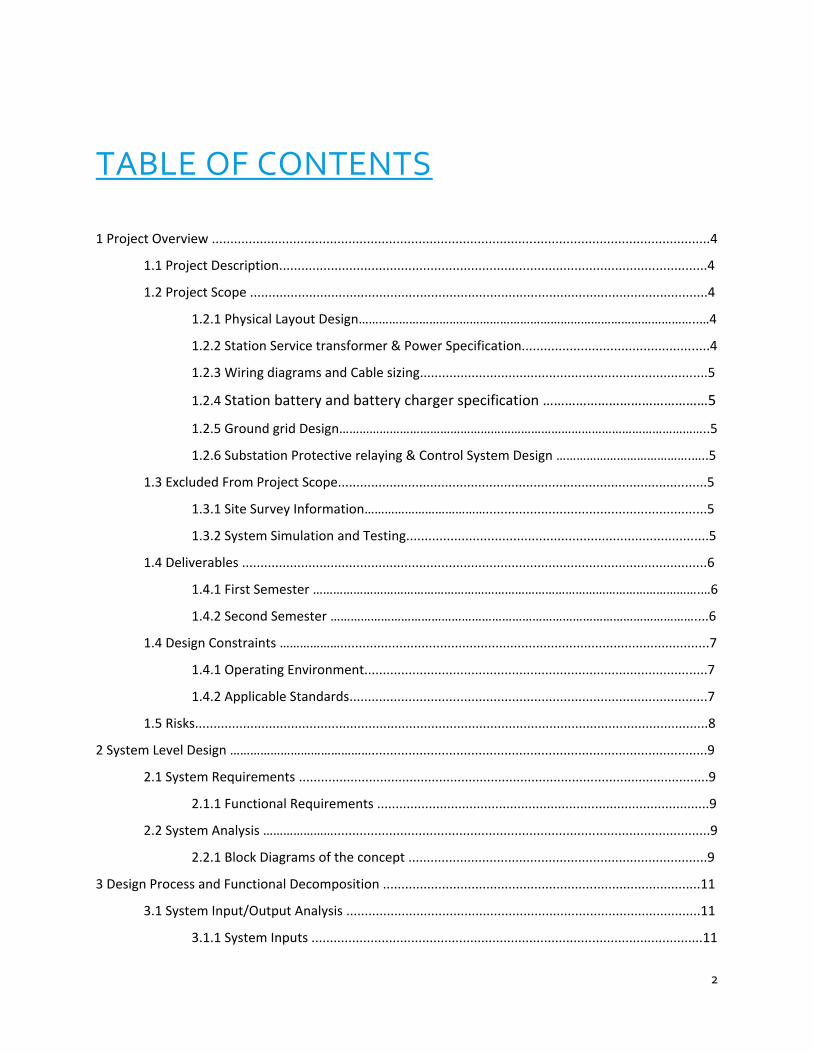
TABLE OF CONTENTS
1 Project Overview .......................................................................................................................................4
1.1 Project Description....................................................................................................................4
1.2 Project Scope ............................................................................................................................4
1.2.1 Physical Layout Design………………………………………………………………………………………..…4
1.2.2 Station Service transformer & Power Specification...................................................4
1.2.3 Wiring diagrams and Cable sizing..............................................................................5
1.2.4 Station battery and battery charger specification ………………………………………5
1.2.5 Ground grid Design………………………………………………………………………………………………..5
1.2.6 Substation Protective relaying & Control System Design ………………………………….…..5
1.3 Excluded From Project Scope....................................................................................................5
1.3.1 Site Survey Information………………………………............................................................5
1.3.2 System Simulation and Testing..................................................................................5
1.4 Deliverables ..............................................................................................................................6
1.4.1 First Semester …………………………………………………………………………………………………….…6
1.4.2 Second Semester ………………………………………………………………………………………………....6
1.4 Design Constraints ………………....................................................................................................7
1.4.1 Operating Environment.............................................................................................7
1.4.2 Applicable Standards.................................................................................................7
1.5 Risks...........................................................................................................................................8
2 System Level Design ……………………………………...........................................................................................9
2.1 System Requirements ...............................................................................................................9
2.1.1 Functional Requirements ..........................................................................................9
2.2 System Analysis …………………......................................................................................................9
2.2.1 Block Diagrams of the concept .................................................................................9
3 Design Process and Functional Decomposition ......................................................................................11
3.1 System Input/Output Analysis ................................................................................................11
3.1.1 System Inputs ..........................................................................................................11

3
3.1.2 System Outputs .......................................................................................................11
3.2 Hardware/Software specifications ……....................................................................................11
3.2.1 Simulations and modelling ......................................................................................11
3.3 Procedures and Specifications.................................................................................................11
3.3.1 Testing …………………………….......................................................................................11
3.3.2 Implementation Issues ….........................................................................................12
4 Design Decisions Discussion and Justification .........................................................................................12
4.1 One Line Diagram ....................................................................................................................12
4.1.1 Formation ................................................................................................................13
4.2 Control House Layout..............................................................................................................15
5 Work Plan ................................................................................................................................................16
5.1 Scheduling: Aug 26, 2014 - Dec 19, 2014 ………….....................................................................16
5.2 Work Breakdown Structure ....................................................................................................17
5.3 Resource Allocation ……………………………………………………………………………………………………………17
6 Conclusion………………………………………………………………………………………………………………………………………….18
LIST OF FIGURES
Figure 1: Block Diagram…………………………………………………………………………………………………………………………10
Figure 2: One Line Diagram…………………………………………………………………………………………………………………...13
Figure 3: Bus configuration …………………………………………………………………………………………………………………..13
Figure 4: Control House Building Plan View…………………………………………………………………………………………..14
Figure 5: Control House Cable Tray View……………………………………………………………………………………………...15
Figure 6: Control House Lighting View…………………………………………………………………………………………………..15
4
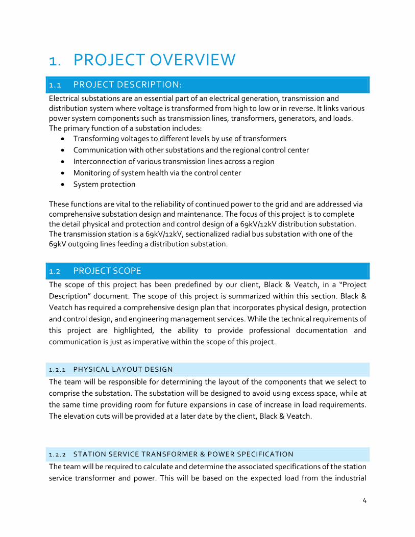
1. PROJECT OVERVIEW
1.1 PROJECT DESCRIPTION:
Electrical substations are an essential part of an electrical generation, transmission and distribution system where voltage is transformed from high to low or in reverse. It links various power system components such as transmission lines, transformers, generators, and loads. The primary function of a substation includes:
Transforming voltages to different levels by use of transformers
Communication with other substations and the regional control center
Interconnection of various transmission lines across a region
Monitoring of system health via the control center
System protection These functions are vital to the reliability of continued power to the grid and are addressed via comprehensive substation design and maintenance. The focus of this project is to complete the detail physical and protection and control design of a 69kV/12kV distribution substation. The transmission station is a 69kV/12kV, sectionalized radial bus substation with one of the 69kV outgoing lines feeding a distribution substation.
1.2 PROJECT SCOPE
The scope of this project has been predefined by our client, Black & Veatch, in a “Project
Description” document. The scope of this project is summarized within this section. Black &
Veatch has required a comprehensive design plan that incorporates physical design, protection
and control design, and engineering management services. While the technical requirements of
this project are highlighted, the ability to provide professional documentation and
communication is just as imperative within the scope of this project.
1.2.1 PHYSICAL LAYOUT DESIGN
The team will be responsible for determining the layout of the components that we select to
comprise the substation. The substation will be designed to avoid using excess space, while at
the same time providing room for future expansions in case of increase in load requirements.
The elevation cuts will be provided at a later date by the client, Black & Veatch.
1.2.2 STATION SERVICE TRANSFORMER & POWER SPECIFICATION
The team will be required to calculate and determine the associated specifications of the station
service transformer and power. This will be based on the expected load from the industrial
5
center’s load. After selecting the transformer, sizing will be determined for other associated
components of the substation.
1.2.3 WIRING DIAGRAMS & CABLE SIZINGS
Proper documentation of the design and wiring diagrams will be provided by the senior design
team. Wiring diagrams will be needed for both within the control house and outside. The inside
of the control house will focus on panel wiring. Outside the control house, we will need to
properly connect all conductors. In addition, based on rated loads, we will need to verify that the
conductors are properly sized to handle power and current requirements.
1.2.4 STATION BATTERY & BATTERY CHARGER SPECIFICATION
A battery is needed prior to the development of the control house. The design team is expected
to carry out the sizing of the batteries, battery chargers, and panels that will utilize this system.
The team will need to consider the length of time to provide power via the battery to the service
station based upon traditional service station outages.
1.2.5 GROUNDING GRID DESIGN
An essential part of the substation design is the design and layout of the grounding grid. We do
not currently know which grounding software we will utilize. The client will provide us with a
suggestion at a later date. The design of the grounding grid will follow all appropriate standards
for the conductors’ ability to handle rated fault currents.
1.2.6 SUBSTATION PROTECTIVE RELAYING & CONTROL SYSTEM DESIGN
The team will be expected to design a protective relaying scheme for the substation. This will
include circuit breakers, circuit switches, and other components. All models will be verified for
proper operation via their datasheets.
1.3 EXCLUDED FROM PROJECT SCOPE
1.3.1. SITE SURVEY INFORMATION
The design team will not be expected to evaluate and consider different geographical areas for
feasibility of potential siting. The client has agreed to provide the design team with elevation
cuts at a later date.

6
1.3.2. SYSTEM SIMULATION AND TESTING
While all due diligence will be paid to make sure the system is built for safe and reliable
operation, no simulations will be ran on the design. No other type of formal testing will be done
with the exception of the grounding software to be chosen. Verification of the team’s design
documents will be done via design review meetings with the client, Black & Veatch. A review
with external professionals is also planned.
1.4 DELIVERABLES
The following list of expected deliverables was set forth by Black & Veatch. The first deliverable is the development of an engineering man-hour budget and schedule for this project in order to plan the overall senior design project. Black & Veatch will work with our team to manage the scope of the project to allow completion during the Fall and Spring semesters.
Some examples of these deliverables include, but are not limited to, equipment sizing calculations, substation layout drawings, station power design, protection and control schematics & project schedules.
1.4.1. FIRST SEMESTER (FALL 2014)
● Development of an engineering man-hour budget and schedule for the project with tracking
of hours spent on each task (for comparison to actual budgeted engineering man-hours,
presented at each design review)
● Design One-line Diagram
● Design Panel Layouts
● Design Schematic Document
● Calculations to determine service transformer and station power requirements
● Selection of equipment size and requirements including circuit breaker, disconnect switches,
CCVTs, PTs, station service transformer, etc
1.4.2. SECOND SEMESTER (SPRING 2015)
● Calculations to determine battery and battery charger size
● Calculations to determine cable sizing
● Calculations to determine grounding requirements
● Complete Wiring Diagrams
● Design Physical Layout
● Bus and Insulator Design
● Design Justifications
● Three-line Diagrams
7
1.4 DESIGN CONSTRAINTS
1.4.1 OPERATING ENVIORNMENT
As this project is about building a hypothetical substation, the environment and weather of the
location will serve as constraints for this project. Though these will not directly affect any of
our calculations, these constraints need to be taken into account when considering soil type,
humidity, temperatures, snow etc. All of these parameters will affect some of our layout
design such as foundation planning and grounding.
1.4.2 STANDARDS APPLICABLE
Standards will play a significant role in optimizing the design process and will serve as rigid
design constraints. There are several standards set by international authorities that will govern
the design of this substation. Below are a few of the primary standards that are appropriate in
terms of the early phases of the project’s development. As the project progresses, more
standards will be explored and documented.
Environmental Standards
RUS Environmental Policies and Procedures, 7 CFR 1794
This Regulation specifies RUS environmental requirements pursuant to the implementation of the National Environmental Policy Act of 1969 and Council on Environmental Quality Regulations. It also references additional authorities, directives, and instructions relevant to protection of the environment.
Public Safety
Substations should be safe for people who may have occasion to be near them. The primary means of ensuring public safety at substations is by erecting a suitable barrier such as a metal fence. Unless local restrictions are more conservative, the fence needs to meet the minimum requirements set by IEEE St. 1119, ‘IEEE guide for Fence Safety Clearances.”
Weather
As dependence on the use of electricity grows, it is increasingly important that substations operate more reliably in extremes of weather than in the past. The substation must be impervious to snow damage and consideration needs to be given to snow accumulation and maintenance of clearances. Extreme
8
temperatures could affect circuit breakers, relay protection, or the bus. Hence the engineer should seek local data on this weather variable.
Foundation Standards
IEEE Std. 691
The objective of this guide is to provide valuable information on design methods for foundation design engineers. The information contained in this guide covers the different kind of foundations for various types of transmission structures; drilled shafts, pile foundations, and anchors; and procedures for conducting load tests.
Power Transformer Standard
Power transformers need special care in their application, specification and procurement because of their great importance and complexity. Hence they need to follow some industry standards and guides of national organizations such as the American National Standards Institute (ANSI), IEEE, etc., and RUS IP 202-1, ‘List of Materials Acceptable for use on Systems of RUS Electrification Borrowers.’
Grounding Standards
The most recommended authoritative guide for grounding safety and standard: IEEE Std. 80, “Guide for Safety in Substation Grounding”
1.5 RISKS
Designing a substation often involves some risks associated with it. While designing a substation, the designers need to consider various risks such as its location, its weather conditions, protection, control and complying with project deadlines. Proximity of the substations to wetlands is essential in order to avoid flooding and its proximity to animals such as rodents can have some adverse effects on the substation functioning. In a similar way, the selection of appropriate protection and control is critical to avoid risk.
1.5.1 RISKS TO THE PROJECT TIMELINE
It is easy to get distracted and wander off from the project timeline. Best possible practices and measures should be taken to work hand-in-hand with the planned project timeline.
9
2. SYSTEM LEVEL DESIGN 2.1 SYSTEM LEVEL REQUIREMENTS
2.1.1 FUNCTIONAL REQUIREMENTS
Due to the theoretical nature of this project, no physical items are expected as deliverables. The requirements given are all necessary to the proper design of a functional distribution substation. Therefore, the following requirements are considered to be functional:
Development of an engineering man-hour budget and schedule for the project with tracking of hours spent on each task (for comparison to actual budgeted engineering man-hours, presented at each design review)
Substation layout of the sectionalized radial transmission substation
Calculations to determine station power requirements
Calculations to determine battery and battery charger size
Calculations to determine cable sizing
Calculations to determine grounding requirements
Selection of equipment size and requirements including circuit breaker, disconnect switches, CCVTs, PTs, station service transformer, etc.
Development of protection and control design documents based upon the protective relay scheme identified by B&V
2.2 SYSTEM DESIGN
2.2.1 CONCEPT BLOCK DIAGRAM
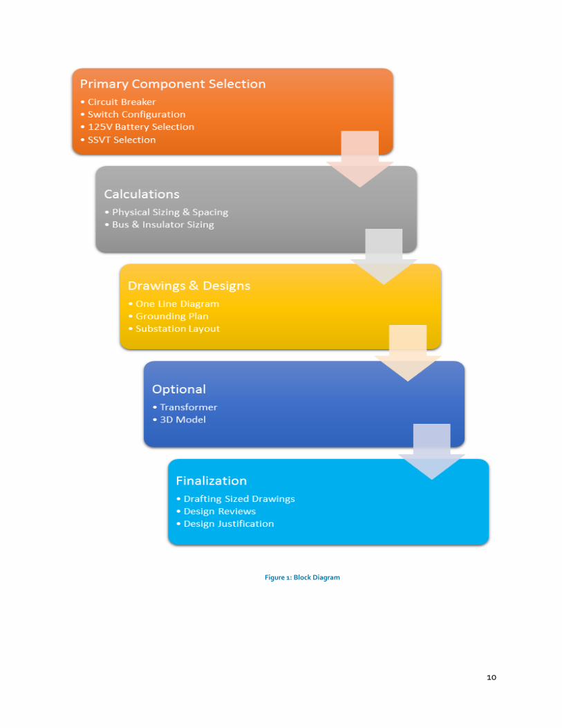
This project has been divided up into five different design phases to organize the design process more effectively and improve the efficiency of our work. The following block diagram outlines the five phases and their intermediate steps.
10
Figure 1: Block Diagram
11
3. DESIGN PROCESS AND FUNCTIONAL
DECOMPOSITION 3.1 SYSTEM INPUT/OUTPUT ANALYSIS
The substation is a sectionalized radial bus system with one incoming line and three outgoing
lines.
3.1.1 SYSTEM INPUTS
The input to the system is a line carrying power delivered from transmission lines coming from
a transmission substation. This is labeled “HS Volts line” on the one-line diagram. This line has
communications signals which are sent with one phase of the power line and later filtered off
the power line using a wave filter.
3.1.2 SYSTEM OUTPUTS
The system has three outgoing lines, labeled “Cir 1”, “Cir 2”, and “Cir 3.” One of these lines is
feeding an industrial load. Each relay within the substation can be considered a subsystem with
its own outputs.
3.2 HARDWARE/SOFTWARE SPECIFICATIONS
The project is entirely software based and no physical deliverables are required. We will
primarily be working with AutoCAD.
3.2.1 SIMULATIONS AND MODELING
The project will be almost entirely modeled in AutoCAD. The one-line diagram, three line-
diagram, physical layout, control house arrangement, panel layouts, and AC/DC Auxiliary
system schematics will all be developed in AutoCAD. The only deliverable that will not be
developed in AutoCAD will be the grounding system. The grounding system will be developed
using WinIGS.
Simulations will not be required for our project. Only the software models are included in the
deliverables.
3.3 PROCEDURES AND SPECIFICATIONS
3.3.1 TESTING
No formal testing is required for the project since we are only providing software models of the
substation. We will verify our designs by consulting with professional engineers at Black and

12
Veatch. Professor Dr. Ajjarapu will be looking over our designs as well. Black and Veatch
conducts internal reviews of its substation design documents within the company, so this
process reflects the industry’s standards.
3.3.2 IMPLEMENTATION ISSUES
There are many challenges associated with this project. Each of our project group members
had little to no substation knowledge before starting this project so we have all needed to learn
an immense amount of information about substations before beginning the design process.
Finding a good starting point for the design process was difficult because the research process
is quite extensive.
4. DESIGN DECISIONS, DISCUSSIONS
AND JUSTIFICATIONS 4.1 ONE LINE DIAGRAM
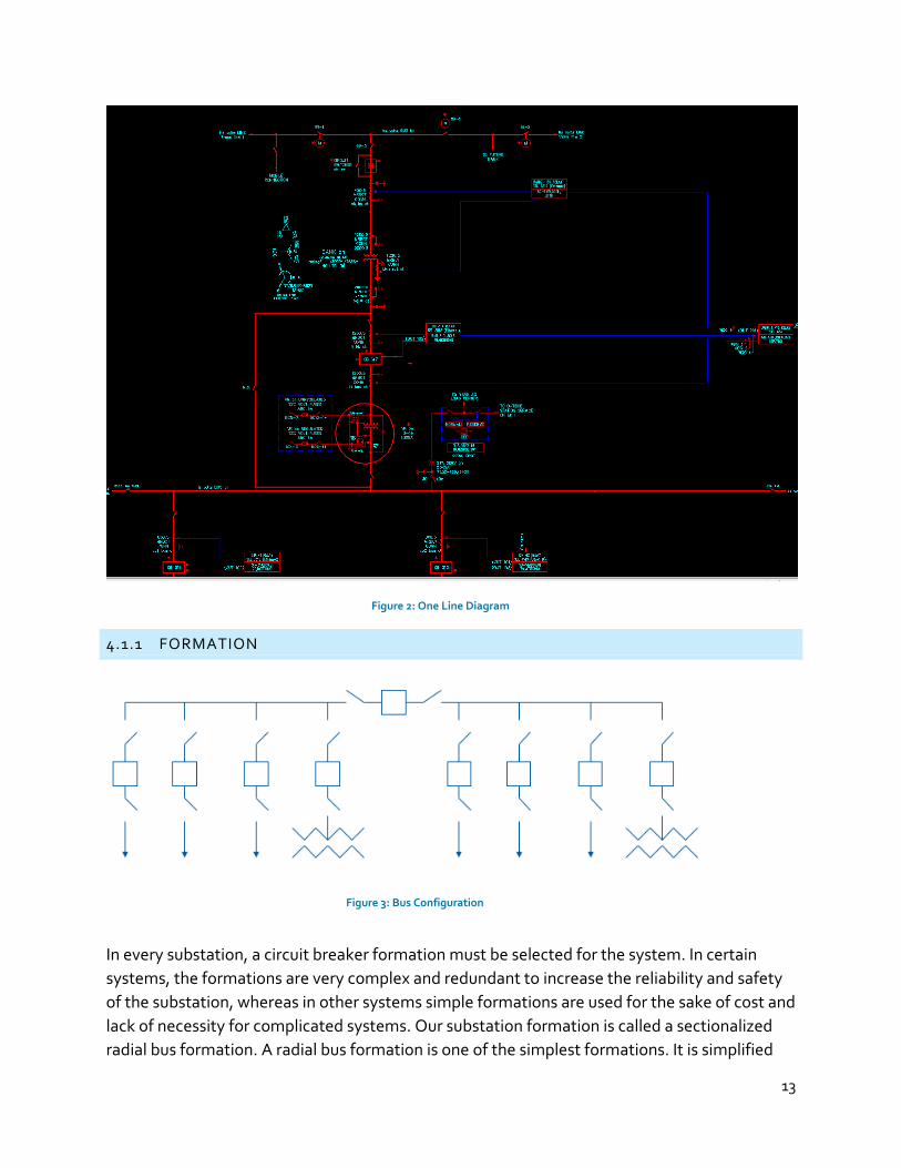
The one line diagram is a simplified graphical representation of three phase power system. Electrical
equipment such as circuit breakers, transformers, capacitors, bus bars and conductors are shown by
standardized schematic symbols. Elements on the diagram do not represent the physical size or
location of the equipment. The one line diagram we came up with is as follows:
13
Figure 2: One Line Diagram
4.1.1 FORMATION
In every substation, a circuit breaker formation must be selected for the system. In certain
systems, the formations are very complex and redundant to increase the reliability and safety
of the substation, whereas in other systems simple formations are used for the sake of cost and
lack of necessity for complicated systems. Our substation formation is called a sectionalized
radial bus formation. A radial bus formation is one of the simplest formations. It is simplified
Figure 3: Bus Configuration
14
and low in cost, but if a circuit breaker fails to trip, the entire substation is lost. To prevent loss
of the entire substation, a sectionalizing circuit breaker is added on the bus. If there is a fault on
the bus, a sectionalizing circuit breaker will trip and protect the rest of the substation. It is
called a sectionalizing bus because they divide the substation up into sections. The following
image is a sectionalizing radial bus.
4.2 CONTROL HOUSE LAYOUT
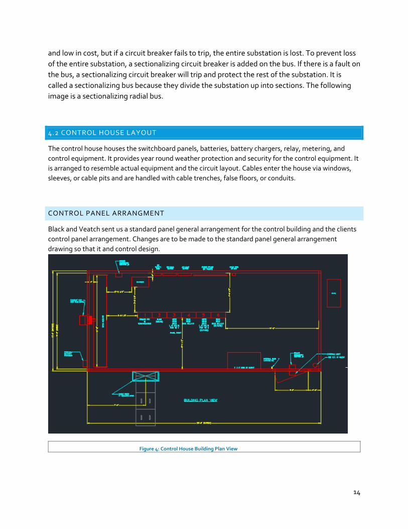
The control house houses the switchboard panels, batteries, battery chargers, relay, metering, and
control equipment. It provides year round weather protection and security for the control equipment. It
is arranged to resemble actual equipment and the circuit layout. Cables enter the house via windows,
sleeves, or cable pits and are handled with cable trenches, false floors, or conduits.
CONTROL PANEL ARRANGMENT
Black and Veatch sent us a standard panel general arrangement for the control building and the clients
control panel arrangement. Changes are to be made to the standard panel general arrangement
drawing so that it and control design.
Figure 4: Control House Building Plan View

15
Figure 5: Control House Cable Tray View
Figure 6: Control House Lighting View
16
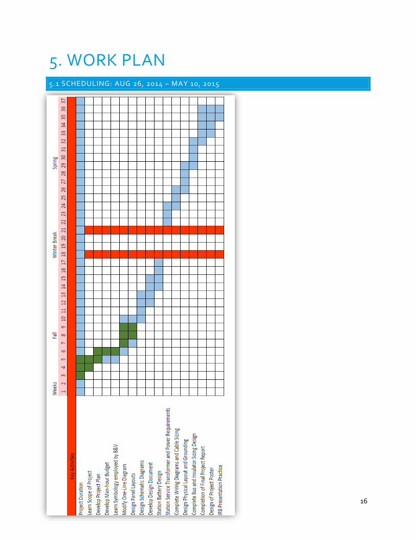
5. WORK PLAN 5.1 SCHEDULING: AUG 26, 2014 – MAY 10, 2015
17
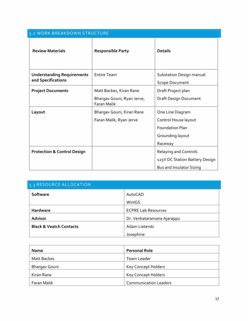
5.2 WORK BREAKDOWN STRUCTURE
Review Materials
Responsible Party
Details
Understanding Requirements and Specifications
Entire Team Substation Design manual
Scope Document
Project Documents Matt Backes, Kiran Rane
Bhargav Gouni, Ryan Jerve, Faran Malik
Draft Project plan
Draft Design Document
Layout Bhargav Gouni, Kiran Rane
Faran Malik, Ryan Jerve
One Line Diagram
Control House layout
Foundation Plan
Grounding layout
Raceway
Protection & Control Design Relaying and Controls
125V DC Station Battery Design
Bus and Insulator Sizing
5.3 RESOURCE ALLOCATION
Software AutoCAD
WinIGS
Hardware ECPRE Lab Resources
Advisor Dr. Venkataramana Ajarappu
Black & Veatch Contacts Adam Lieterski
Josephine
Name Personal Role
Matt Backes Team Leader
Bhargav Gouni Key Concept Holders
Kiran Rane Key Concept Holders
Faran Malik Communication Leaders
18
Ryan Jerve Communication Leaders
Sohail Suryavanshi Webmaster
6. CONCLUSION This senior design project has helped us learn the physical, protection, and control design of a
69kV/12kV distribution substation along with the different components that are used within a
substation. As a team, we developed an engineering man-hour budget, one-line diagram, three-line
diagram, panel layout design, schematics, bus and insulator design, and selected equipment sizes for
various component along with performing various substation level calculations. This project was very
helpful in learning about the various components that are used within a distribution substation. We
obtained real world experience by working with an off-campus client virtually along with learning to
deal with time constraints and working as a team.