Embed Size (px)
Citation preview
6800 Spin Coater Series Model 6808, 6808P, and 6812P Spin Coater
Operator’s Manual
System Serial Number: ________________
Prepared for: ________________________
Make certain that everyone associated with this instrument
becomes knowledgeable about the material contained in this manual before using the equipment.
7645 Woodland Drive, Indianapolis, IN 46278-2707
Customer Service: P 317. 244.1200 F 317.240.2073 E [email protected]
COPYRIGHT SPECIALTY COATING SYSTEMS
05/27/10

OM-813-1002 Operator’s Manual Rev 8
SCS 6800 SPIN COATER SECTION 1: TABLE OF CONTENTS i
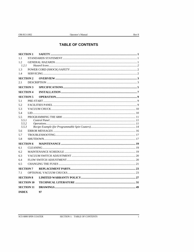
TABLE OF CONTENTS
SECTION 1 SAFETY .......................................................................................................................... 1
1.1 STANDARDS STATEMENT ......................................................................................................... 1
1.2 GENERAL HAZARDS ................................................................................................................... 1 1.2.1 Hazard Icons ............................................................................................................................ 2
1.3 POWER CORD (SHOCK) SAFETY .............................................................................................. 2
1.4 SERVICING .................................................................................................................................... 2
SECTION 2 OVERVIEW ................................................................................................................... 3
2.1 DESCRIPTION ............................................................................................................................... 3
SECTION 3 SPECIFICATIONS ........................................................................................................ 5
SECTION 4 INSTALLATION ........................................................................................................... 7
SECTION 5 OPERATION .................................................................................................................. 9
5.1 PRE-START .................................................................................................................................... 9
5.2 FACILITIES PANEL ...................................................................................................................... 9
5.3 VACUUM CHUCK ....................................................................................................................... 10
5.4 LID ................................................................................................................................................. 10
5.5 PROGRAMMING THE 6800 ....................................................................................................... 11 5.5.1 Control Panel ......................................................................................................................... 11 5.5.2 Operations .............................................................................................................................. 11 5.5.3 Recipe Example (for Programmable Spin Coaters) ............................................................... 14
5.6 ERROR MESSAGES .................................................................................................................... 16
5.7 TROUBLESHOOTING ................................................................................................................. 17
5.8 SHUTDOWN ................................................................................................................................. 17
SECTION 6 MAINTENANCE ......................................................................................................... 19
6.1 CLEANING ................................................................................................................................... 19
6.2 MAINTENANCE SCHEDULE .................................................................................................... 19
6.3 VACUUM SWITCH ADJUSTMENT .......................................................................................... 20
6.4 FLOW SWITCH ADJUSTMENT ................................................................................................. 20
6.5 CHANGING THE FUSES ............................................................................................................ 21
SECTION 7 REPLACEMENT PARTS ............................................................................................ 23
7.1 OPTIONAL VACUUM CHUCKS ................................................................................................ 23
SECTION 8 LIMITED WARRANTY POLICY ............................................................................. 27
SECTION 10 TECHNICAL LITERATURE ..................................................................................... 31
SECTION 11 DRAWINGS .................................................................................................................. 49
INDEX 97
Rev 8 Operator’s Manual OM-813-1002
ii TABLE OF CONTENTS SCS 6800 SPIN COATER
TABLE OF FIGURES
Figure 5-1: Facilities Panel ........................................................................................................................... 9
Figure 5-2: Control Panel ............................................................................................................................ 11
Figure 5-3: Recipe Example ....................................................................................................................... 14
Figure 6-1: Vacuum Switch Adjustment .................................................................................................... 20
Figure 6-2: Fuse Replacement .................................................................................................................... 21
OM-813-1002 Operator’s Manual Rev 8
SCS 6800 SPIN COATER SECTION 1: SAFETY 1
SECTION 1 SAFETY
1.1 STANDARDS STATEMENT
This machine has been designed to be used as described in this manual. Operator safety and safe reliable
product coating were key elements in the design. The machine complies with all applicable sections of the
NFPA article 79, of the National Electric Code (NEC). All commercially standard components used in
this machine have a minimum UL and/or CSA ratings. Components built to CE standards have been used
wherever possible. Any local or regional certifications required above and beyond the aforementioned are
the responsibility of the customer.
1.2 GENERAL HAZARDS
WARNING: Improper operation or service of this machine can result in serious
injury or death. Read and understand this manual before operating or servicing
this machine.
DANGER: Do not use a 6800 spin coater in the presence of an explosive atmosphere. These
machines are not classified as Intrinsically Safe.
DANGER: Use this machine only under an exhaust hood.
WARNING: Do not touch or hold the shaft or chuck while any machine component is in motion.
WARNING: Purging with N2 or clean, dry air is required as a safety factor to fill the interior of the
machine and exclude dangerous gasses.
WARNING: If a Motion Error occurs, machine components will not stop if the lid is lifted. Do not
remove the lid until the chuck has stopped spinning.
WARNING: Do not operate this machine if the lid is not in place.
WARNING: Do not attempt to access any internal parts if the power cord is connected. Disconnect
the power cord from the outlet and wait 10 minutes before servicing this machine to avoid any high
voltage that may exist for a period of time after the power is removed.
CAUTION: Connect the power plug to a grounded outlet only.
CAUTION: Review Material Safety Data Sheets for information about any chemicals used with this
machine and the possible toxicity or reaction with the spin coater bowl or drain.
IMPORTANT: The external vacuum pump periodically requires additional oil. Let the pump sit for
six hours with the oil prior to starting the pump. See the pump manual for additional details. Pump
seals will burn out if proper instructions are not followed.

Rev 8 Operator’s Manual OM-813-1002
2 SECTION 1: SAFETY SCS 6800 SPIN COATER
1.2.1 HAZARD ICONS
The following symbols may occur at points throughout the rest of the manual. Note and read each
warning before attempting any operations associated with it.
This symbol warns of the potential for an ELECTRICAL SHOCK.
This symbol signifies a GENERAL WARNING, which accompanying text will explain.
1.3 POWER CORD (SHOCK) SAFETY
Emergency Power Disconnect options: Use the power cord as a disconnecting device.
To facilitate disconnect, make sure the power outlet for this cord is readily accessible to the
operator.
Note for international users: Select the plug that is rated for the supply circuit voltage that is
available. The supply circuit must be overcurrent protected at a value not exceeding 6 amps.
1.4 SERVICING
Before servicing, remove all power.
Note: High voltage may still be present after shutdown and disconnecting line power. Allow unit
to set without power for 10 minutes before servicing. If it becomes necessary to perform
diagnostic service while certain areas of the machine still have power, use only qualified
personnel. Follow all normal industrial safety practices when dealing with electrical components.
Review and understand the electrical schematic before attempting any electrical diagnostic
service.

OM-813-1002 Operator’s Manual Rev 8
SCS 6800 SPIN COATER SECTION 2: OVERVIEW 3
SECTION 2 OVERVIEW
2.1 DESCRIPTION
The 6800 Spin Coater Series is a family of compact spin coaters for low production spin coating
applications and experimentation.
The 6800 Spin Coater Series provides the ability to hold a product with a vacuum chuck and spin that
chuck at precise speeds and for controlled periods of time. Operations are extremely repeatable and are
settable to 0.1 second. The chuck is indexed back to its initial position at the end of each cycle, so that
each wafer may be oriented the same way on the chuck. See the Specifications Section for more
information.
Operation of the spin coater is controlled by a user-friendly keypad. During a cycle, the spinning speed
and remaining time are displayed on a user interface screen. The acceleration and deceleration rates are
calculated by the controller to provide various ramp profiles. A recipe contains cycle information such as
speed, ramp up time, ramp down time, and dwell time at speed.
The 6800 Spin Coater Series is available in 8 inch and 12 inch bowls.
Use of this machine for anything but its intended purpose may create a safety hazard and voids the
equipment warranty.

Rev 8 Operator’s Manual OM-813-1002
4 SECTION 2: OVERVIEW SCS 6800 SPIN COATER

OM-813-1002 Operator’s Manual Rev 8
SCS 6800 SPIN COATER SECTION 3: SPECIFICATIONS 5
SECTION 3 SPECIFICATIONS
The 6808 Spin Coater can store one recipe with a maximum of 4 steps. The 6808P and 6812P Spin Coater
can store up to 3 recipes, with a maximum of 8 steps in each recipe.
Speed 0–9,999 RPM
Acceleration/ Deceleration 0.1–30.0 Seconds (in 0.1 Sec. Increments)
Dwell (Spin Time) each step Up to 999 Seconds (in 1.0 Sec. Increments)
Dimensions Depth 18.0" (45.72 cm)
Width 13.25" (33.66 cm)
Height 10.8" (27.43 cm)
Weight 41 lbs. (18.6 kg)
Power Input 120/240VAC, 1 Phase, 300VA
Vacuum Input (required) 430 to 635 mm Hg
(17" to 25" Hg)
Purge Input (required) 0.55 cfm at 5 psi (N2 or clean, dry air)
Optional Features:
External Vacuum Pump (external) 115VAC 60Hz / 230VAC 50 Hz
5.5A 1 Phase
Software for external programming and program storage.
Dispense unit with four dispense needles and two material tanks.
Additional Specifications:
It is recommended that a shut-off valve be installed upstream of the unit on the N2 or clean, dry
air supply. SCS does not supply a shut-off valve.
Purging (using N2 or clean, dry air) to fill the interior of the machine with inert N2 or clean, dry
air and exclude dangerous gasses is required as a safety factor.
For safety reasons, the machine will not power up without a purge flow of at least
0.55 cfm of N2 or clean, dry air.
The spin coater will not operate without vacuum.
For safety reasons, the machine will shut off if the lid is removed.
Comment [RBT1]: Shouldn't we have fuse specs??

Rev 8 Operator’s Manual OM-813-1002
6 SECTION 3: SPECIFICATIONS SCS 6800 SPIN COATER
OM-813-1002 Operator’s Manual Rev 8
SCS 6800 SPIN COATER SECTION 4: INSTALLATION 7
SECTION 4 INSTALLATION
Note for international applications: The spin coater is provided to international users with an
unterminated power cord so that the appropriate power plug (non-locking 250V, 10A), may be attached.
The plug must meet the requirements of IEC227 or IEC245.
Note: The supply circuit must be overcurrent protected at a value not exceeding 6 amps.
Do not apply power until all connections have been made.
1. Place the unit on a solid, level surface, free from vibration and temperature extremes. For optimum
performance, make sure the chuck is level.
2. Refer to the Specifications section or to the nameplate on the machine for electrical requirements.
3. The machine will not operate without purging N2 or clean, dry air (0.55 cfm) connected to the “N2”
port in the back of the machine. Purge N2 or clean, dry air is required as a safety factor to fill the
interior of the console unit and exclude dangerous gasses.
4. External vacuum is also required for the machine to operate. Connect external vacuum to the
“Vacuum” port on the Utility Panel, or use the optional pneumatic-powered vacuum pump.
5. Install and connect any additional options (such as a footswitch or dispenser) before connecting the
spin coater power.
Note: The 6800 Spin Coater is not for use in a hazardous atmosphere.

Rev 8 Operator’s Manual OM-813-1002
8 SECTION 4: INSTALLATION SCS 6800 SPIN COATER
OM-813-1002 Operator’s Manual Rev 8
SCS 6800 SPIN COATER SECTION 5: OPERATION 9
SECTION 5 OPERATION
This machine is designed for use in a normal laboratory or manufacturing working environment; avoid
temperature extremes and vibration.
5.1 PRE-START
1. Connect the N2 or clean, dry air purge supply and vacuum.
NOTE: The unit will not operate without the vacuum and N2 or clean, dry air purge.
2. Attach the spin coater and external vacuum pump power cords to a properly grounded outlet. (See the
pump operation instructions in the technical literature section to start the vacuum pump.)
3. Verify that the vacuum chuck is secure.
4. Turn the power switch on (located on the facilities panel).
Remember that the unit will not run unless programmed, and that the lid must be opened and closed
before each cycle (indicating that material has been placed in the spin coater).
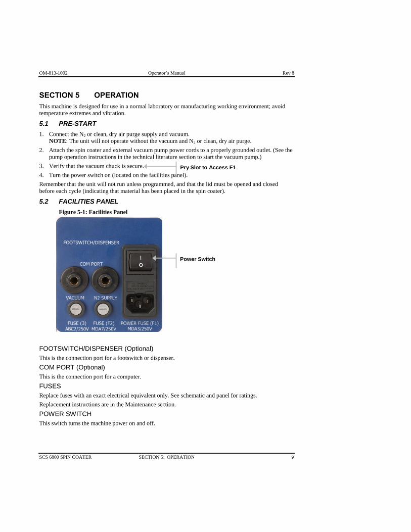
5.2 FACILITIES PANEL
Figure 5-1: Facilities Panel
FOOTSWITCH/DISPENSER (Optional)
This is the connection port for a footswitch or dispenser.
COM PORT (Optional)
This is the connection port for a computer.
FUSES
Replace fuses with an exact electrical equivalent only. See schematic and panel for ratings.
Replacement instructions are in the Maintenance section.
POWER SWITCH
This switch turns the machine power on and off.
Power Switch
Pry Slot to Access F1
Rev 8 Operator’s Manual OM-813-1002
10 SECTION 5: OPERATION SCS 6800 SPIN COATER
VACUUM
This is the external vacuum supply connection. using 1/4" OD tube fitting (430 to 635 mm Hg or 17 to 25
inches Hg).
Note: The unit will not complete a cycle without a vacuum.
N2 SUPPLY
This is the connection for the N2 or clean, dry air supply to maintain positive pressure in the enclosure
(0.55 cfm at 2 psi nitrogen or clean, dry air).
Note: The machine will not operate without N2 or clean, dry air.
5.3 VACUUM CHUCK
Chucks are machined to close tolerances and provide an exceptionally flat, rigid surface for mounting
objects of different sizes, weights, and shapes. The cross scroll pattern on a chuck distributes vacuum
over the surface and enables rapid vacuum release. The vacuum created holds objects to the chuck while
spinning.
Chuck selection should be based on object size and rigidity. The proper chuck diameter is 1/4 to 1 inch
(0.6 to 2.5cm) smaller than an object’s diameter. The entire object should be supported if it is flexible,
fragile, or if it is to be wiped or brushed during cleaning.
Centering is done manually; use templates and measurements for further assistance when centering.
Use Step 0 in a recipe to set the chuck size. Designate the chuck size appropriately:
1: Chucks up to 1" diameter
2: Chucks up to 2" diameter, and greater than 1" diameter
4: Chucks up to 4" diameter, and greater than 2" diameter
6: Chucks up to 6" diameter, and greater than 4" diameter
5.4 LID
For safety reasons, the machine will not operate without the lid in place. In addition, the lid must be
removed after each cycle is completed (to avoid accidentally dispensing twice on the same object). If the
lid is removed during a cycle, the machine will stop.
Note: In rare instances (heavy chuck, high rotation speed), a Motion Error may occur. Power to the motor
will be cut and the chuck will coast to a stop. This will not damage the machine.
OM-813-1002 Operator’s Manual Rev 8
SCS 6800 SPIN COATER SECTION 5: OPERATION 11
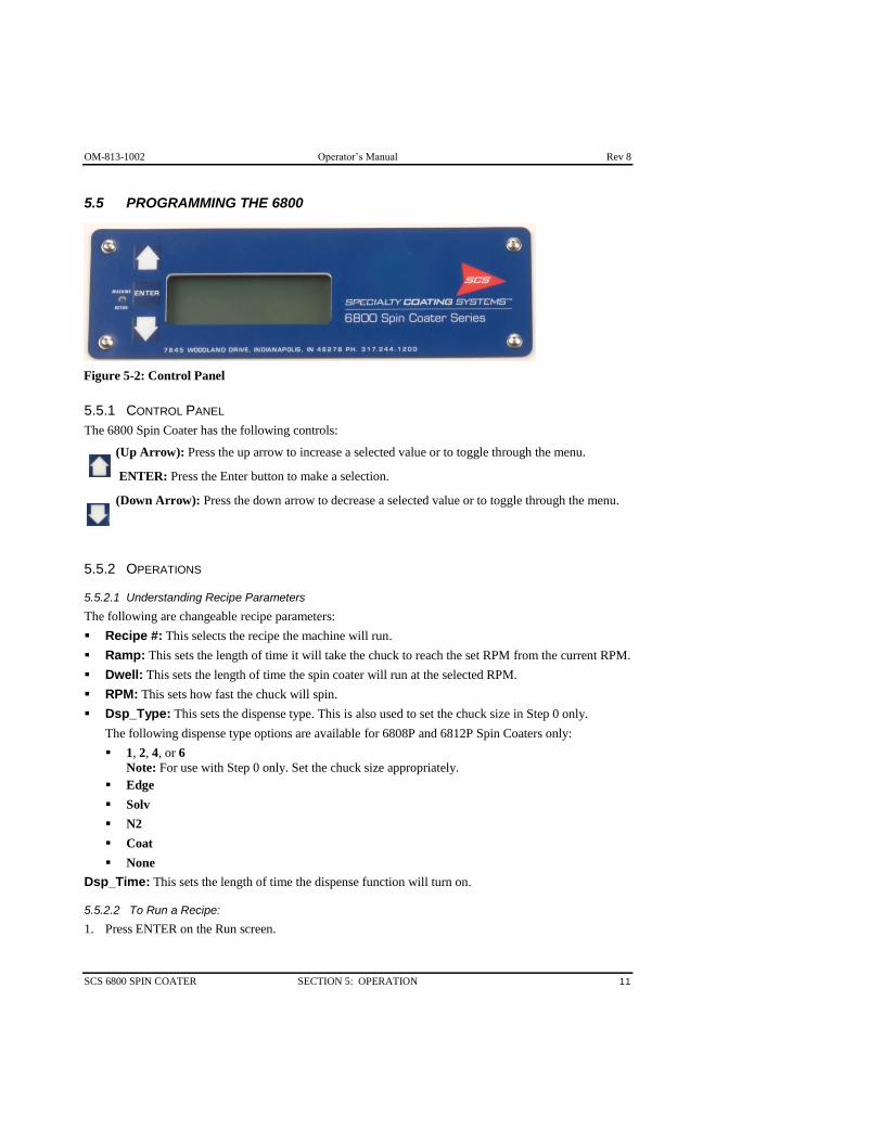
5.5 PROGRAMMING THE 6800
5.5.1 CONTROL PANEL
The 6800 Spin Coater has the following controls:
(Up Arrow): Press the up arrow to increase a selected value or to toggle through the menu.
ENTER: Press the Enter button to make a selection.
(Down Arrow): Press the down arrow to decrease a selected value or to toggle through the menu.
5.5.2 OPERATIONS
5.5.2.1 Understanding Recipe Parameters
The following are changeable recipe parameters:
Recipe #: This selects the recipe the machine will run.
Ramp: This sets the length of time it will take the chuck to reach the set RPM from the current RPM.
Dwell: This sets the length of time the spin coater will run at the selected RPM.
RPM: This sets how fast the chuck will spin.
Dsp_Type: This sets the dispense type. This is also used to set the chuck size in Step 0 only.
The following dispense type options are available for 6808P and 6812P Spin Coaters only:
1, 2, 4, or 6
Note: For use with Step 0 only. Set the chuck size appropriately.
Edge
Solv
N2
Coat
None
Dsp_Time: This sets the length of time the dispense function will turn on.
5.5.2.2 To Run a Recipe:
1. Press ENTER on the Run screen.
Figure 5-2: Control Panel
Rev 8 Operator’s Manual OM-813-1002
12 SECTION 5: OPERATION SCS 6800 SPIN COATER
5.5.2.3 To Stop a Recipe:
1. Press the down arrow on the Run screen.
The recipe will be reset, the chuck will stop spinning, and the display will show an error.
5.5.2.4 To Select a Different Recipe:
1. Press the up arrow on the Run screen.
The Select Recipe screen will appear.
2. Press the up and down arrows to select a recipe.
3. Press ENTER.
The Select Step screen will appear.
4. Press the down arrow to select Run Recipe.
5. Press ENTER.
The Run screen will appear and the new recipe will be selected.
5.5.2.5 To Edit a Recipe:
1. Press the up arrow on the Run screen.
The Select Recipe screen will appear.
2. Press the up and down arrows to select a recipe to edit.
3. Press ENTER.
The Select Step screen will appear.
4. Use the up and down arrows to select a step to edit.
Note: To clear every step in a recipe, select Clr Recipe and hit ENTER.
5. Press ENTER.
The Edit Step screen will appear.
6. Use the up and down arrows to select an item to edit.
7. Press ENTER.
The value for the item can now be adjusted using the up and down arrows. Once the desired value is
selected, press ENTER again.
8. Repeat Steps 6–7 until the recipe step is edited as desired.
9. Repeat Steps 4–8 until the recipe is edited as desired.
OM-813-1002 Operator’s Manual Rev 8
SCS 6800 SPIN COATER SECTION 5: OPERATION 13
5.5.2.6 To Set the Chuck Size:
1. Press the up arrow on the Run screen.
The Select Recipe screen will appear.
2. Press the up and down arrows to select a recipe.
3. Press ENTER.
The Select Step screen will appear.
4. Use the up and down arrows to select Step 0.
5. Press ENTER.
The Edit Step screen will appear.
6. Use the up and down arrows to select Dsp_Type.
7. Press ENTER.
8. Use the up and down arrows to select 1, 2, 4, or 6.
Designate the chuck size appropriately:
1: Chucks up to 1" diameter
2: Chucks up to 2" diameter, and greater than 1" diameter
4: Chucks up to 4" diameter, and greater than 2" diameter
6: Chucks up to 6" diameter, and greater than 4" diameter
9. Press ENTER.

Rev 8 Operator’s Manual OM-813-1002
14 SECTION 5: OPERATION SCS 6800 SPIN COATER
5.5.3 RECIPE EXAMPLE (FOR PROGRAMMABLE SPIN COATERS)
Great flexibility is available in spin coater recipes. Figure 5-3 shows RPM versus time for a recipe that
demonstrates some of the different actions.
The length of a step is shown across the bottom with an arrow. (Step 1 is 18 seconds, total.)
Vertical lines and a number (total seconds) mark each event (start or stop of any ramp, dispense,
or dwell).
Heavy lines show the two dispense operations.
The numbers at the left show the speeds (RPM) used in this recipe.
Boxes across the top illustrate the recipe entries for the seven steps.
Note some of the special capabilities accomplished by the recipe:
Long periods of the same function can be accomplished using multiple steps (Steps 3 & 4).
Sudden speed changes are accomplished by setting Ramp time to zero or a very low number (Step
5). The actual time required is a function of the size of speed change and the amount of weight
being spun.
Pauses at zero RPM can be programmed into the middle of a recipe (Step 5). It is even possible
to program a dispense step at zero RPM if desired.
Dispensing (option): Two dispense options can be employed, one right after the other and at the
same RPM (Steps 1 & 2). They could follow more closely if Dwell 1 were set to 4 instead of 10.
Ramps to different speeds and employing different Accel/Decel rates can be combined
(Steps 6 & 7).
Figure 5-3: Recipe Example
STEP 1
Ramp1 = 8
RPM 1 2000
Dwell 1 = 10
Disp 1 = COAT
Time 1 = 4
STEP 2
Ramp 2 = 0
RPM 2 = 2000
Dwell 2 = 10
Disp 2 = N2
Time 2 = 7
STEP 5
Ramp 5 = 0
RPM 5 = 0
Dwell 5 = 4
Disp 5 = NONE
Time 5 = 0
8 12 18 25 28
65
68 43 58
2000
1400
800
STEP 7
Ramp 7 = 3
RPM 7 = 0
Dwell 7 = 0
Disp 7 = NONE
Time 7 = 0
STEP 6
Ramp 6 = 3
RPM 6 = 2000
Dwell 6 = 0
Disp 6 = NONE
Time 6 = 0
STEP 4
Ramp 4 = 15
RPM 4 = 800
Dwell 4 = 0
Disp 4 = NONE
Time 4 = 0
STEP 3
Ramp 3 = 15
RPM 3 = 1400
Dwell 3 = 0
Disp 3 = NONE
Time 3 = 0
62

OM-813-1002 Operator’s Manual Rev 8
SCS 6800 SPIN COATER SECTION 5: OPERATION 15
The following is a detailed explanation of each step from the Recipe Example illustrated in Figure 5-3.
Note: Settings are numbered according to the step in which they are being used. For example, the settings
in Step1 are called Ramp1, RPM1, Dwell1, etc.
Step 0 is the step that tells the spin coater how large the vacuum chuck is. Enter the size in the Disp
blank by selecting the number that (most nearly) represents the diameter of the chuck. Homing: to stop
the chuck from returning to the Home position at the end of the run, set the step 0 Time to some number
other than 0.
Step 1 begins with a Ramp1-- 8 seconds up to an RPM1 of 2000. Dwell1 is set to keep the speed at
2000 for 10 seconds. Disp1 is set to COAT; the dispensing always begins as soon as the dwell does. The
dispensing Time1 is 4 seconds (as shown by the heavy line), and the dwell continues until its 10 seconds
is up.
Step 2 begins at 18 seconds. It has no Ramp2 time and also has the same speed (2000 RPM) so it
appears to be a continuation of step 1. Its Dwell2 is set to 10 seconds (combined with step 1 this gives a
total dwell of 20 seconds at 2000 RPM). Disp2 is set to N2 and the Time2 is 7 seconds (of N2
dispensing).
Step 3 begins at 28 seconds on the figure, and has a 15-second Ramp3 down to an RPM3 of 1400. The
Dwell3 is set to 0 seconds and there is no Disp3. NOTE that this is half of a 30-second ramp down to
800. Since a 30 second long ramp is not possible, the programmer used two 15-second ramps.
Step 4 is the continuation of the ramp down. The Ramp4 is 15, and the RPM4 is 800.
Step 5 tries to cause an instant stop, followed by 4 seconds without any spinning. The Ramp5 is 0, and
the RPM5 is 0. The Dwell5 is set to 4 seconds. If the motor can stop quickly enough, the cycle will
continue—if the momentum is too great and the motor cannot stop quickly enough, there will be a
“Motion Error.: See the error messages on following page. To avoid the motion error, set Ramp5 to
allow a short amount of time for the ramp down
Steps 6 & 7: consist of two ramps with no dwell time. RPM6 simply goes up to 2000 in the Ramp6 time
of 3 seconds and RPM7 takes it back down to 0 in the Ramp7 time of 3 seconds. If necessary, the Ramp
could be set to longer times, to avoid the motion error.
Rev 8 Operator’s Manual OM-813-1002
16 SECTION 5: OPERATION SCS 6800 SPIN COATER
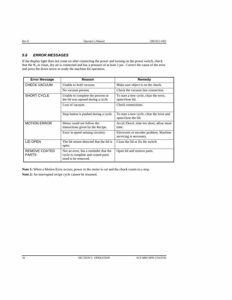
5.6 ERROR MESSAGES
If the display light does not come on after connecting the power and turning on the power switch, check
that the N2 or clean, dry air is connected and has a pressure of at least 2 psi. Correct the cause of the error
and press the down arrow to ready the machine for operation.
Error Message Reason Remedy
CHECK VACUUM Unable to hold vacuum. Make sure object is on the chuck.
No vacuum present. Check the vacuum line connection.
SHORT CYCLE Unable to complete the process or
the lid was opened during a cycle
To start a new cycle, clear the error,
open/close lid.
Loss of vacuum. Check connections.
Stop button is pushed during a cycle. To start a new cycle, clear the error and
open/close the lid.
MOTION ERROR Motor could not follow the
instructions given by the Recipe.
Accel./Decel. time too short; allow more
time.
Error in speed sensing circuitry. Electronic or encoder problem. Machine
servicing is necessary.
LID OPEN The lid sensor detected that the lid is
open.
Close the lid or fix the switch.
REMOVE COATED PARTS
Not an error, but a reminder that the
cycle is complete and coated parts
need to be removed.
Open lid and remove parts.
Note 1: When a Motion Error occurs, power to the motor is cut and the chuck coasts to a stop.
Note 2: An interrupted recipe cycle cannot be resumed.
OM-813-1002 Operator’s Manual Rev 8
SCS 6800 SPIN COATER SECTION 5: OPERATION 17
5.7 TROUBLESHOOTING
PROBLEM POSSIBLE CAUSE ACTION
Spin coater will not
power up.
A N2 or clean, dry air purge is not
present, or inadequate flow.
Verify or provide a N2 or clean, dry air purge.
Have maintenance check sensor FLS-1.
Cycle will not start Error from previous cycle. Press the down arrow to clear the error.
No recipe programmed. Select a recipe.
Vacuum not present. Verify or provide necessary vacuum. Have
maintenance check sensors FLS-1, VS-1.
Lid open/close not sensed, or lid
still open.
Open and close lid. Have maintenance check
sensor S1.
Cycle starts, but
immediately stops
Vacuum lost. Check placement of substrate on chuck, and
check vacuum supply.
Recipe problem. Review, edit, and re-enter recipe as needed.
Displayed time or
RPM does not seem
exact.
The display is an approximation,
only updated when the control
circuitry has available time. Use it
only to verify the correct recipe
choice and steps, and as a rough
report on time and speed.
For exact timing and speed, use external test
equipment and adjust the recipe as needed.
Actual performance is very repeatable.
Recipe "breaks" when
changing speed.
Rapid speed changes are hard with
the larger chuck. If the motor
cannot keep up with the
instructions, a Motion Error occurs.
The motor spins freely until it
comes to a halt, and the error
message is shown.
Change the recipe to allow a more gradual
speed change.
5.8 SHUTDOWN
1. Turn off the power switch (located on the facilities panel).
2. Turn off N2.
3. Carefully remove the vacuum chuck.
4. Clean the vacuum chuck and bowl thoroughly using the proper solvents.

Rev 8 Operator’s Manual OM-813-1002
18 SECTION 5: OPERATION SCS 6800 SPIN COATER

OM-813-1002 Operator’s Manual Rev 8
SCS 6800 SPIN COATER SECTION 6: MAINTENANCE 19
SECTION 6 MAINTENANCE
6.1 CLEANING
Use an appropriate solvent to clean the bowl and lid.
Avoid contact with painted surfaces when using solvents such as N-Methylpyrrolidone (NMP). These
solvents will damage/remove paint.
6.2 MAINTENANCE SCHEDULE
Frequency Task Responsibility
As needed Clean out bowl Operator
Daily Clean
Check N2 or clean, dry air connections
Operator
Weekly Check hoses and fittings
Check electrical connections
Maintenance
Periodically Refer to vendor literature to maintain associated components As appropriate

Rev 8 Operator’s Manual OM-813-1002
20 SECTION 6: MAINTENANCE SCS 6800 SPIN COATER
6.3 VACUUM SWITCH ADJUSTMENT
See Figure 6-1. The Vacuum switch may need adjustment if the “Check Vacuum” error is displayed but
no cause for it is apparent (the vacuum pump is working and the hose & motor shaft hole are not
blocked). In that case:
1. Turn the vacuum adjust screw fully clockwise and turn on the machine and vacuum.
2. Push the START button.
3. While the cycle is running, slowly turn the vacuum adjust counterclockwise until the unit
stops and the "CHECK VACUUM" messages is displayed.
4. Turn back ¼ turn (clockwise).
Verify machine operation.
6.4 FLOW SWITCH ADJUSTMENT
The flow switch is properly adjusted before the spin coater is shipped; if something should make
readjustment necessary follow the appropriate procedure.
Units with internal vacuum pump:
1. Turn power off, remove pressure.
2. Remove the muffler from the top of the flow switch and connect a flow meter.
3. Set the incoming pressure to 60-80 psi.
4. Adjust the needle valve (at the bottom of the flow switch) to give 0.55 cfm.
5. Remove air pressure, then remove the flow meter and replace the muffler.
6. The procedure is complete. Verify machine operation
Units without internal vacuum pump:
1. With machine turned On, adjust flow with incoming pressure regulator up from zero until flow switch
actuates (characters will appear on machine display).
2. Verify actual flow of at least .55cfm using an external gauge.
3. The procedure is complete. Verify machine operation.
Figure 6-1: Vacuum Switch Adjustment
ADJUST
N.O. N.C.
VACUUM
SWITCH
COM

OM-813-1002 Operator’s Manual Rev 8
SCS 6800 SPIN COATER SECTION 6: MAINTENANCE 21
6.5 CHANGING THE FUSES
Fuses F2 and F3 are in commonly used fuse carriers. Turn the cap with a small flat-blade screwdriver
and pull out the fuse and carrier. Replace with only with an exact electrical equivalent.
Fuse F1 is in the main power cord/switch assembly. Note that the correct voltage (115V or 230V) shows
through the voltage display window near the top of the assembly.
1. Above the voltage indication window are two notches. Use a small flat blade screwdriver to pry open
the hinged cover.
2. Inside, is the fuse carrier. Space at the sides will allow you to pry the carrier out. Note which side of
the carrier has the fuse in it.
3. Replace the fuse with an exact electrical equivalent. Make sure the fuse is in the proper side of the
carrier.
4. Return the carrier and press it fully into its holder. Make sure the writing for the correct voltage will
show through the window when the cover is snapped back into place.
5. Press the cover into place (it will snap closed if the fuse carrier is properly seated), and check to see
that the proper voltage number shows through the window.
Figure 6-2: Fuse Replacement
Power Switch
Pry Slot to Access F1

Rev 8 Operator’s Manual OM-813-1002
22 SECTION 6: MAINTENANCE SCS 6800 SPIN COATER
OM-813-1002 Operator’s Manual Rev 8
SCS 6800 SPIN COATER SECTION 7: REPLACEMENT PARTS 23
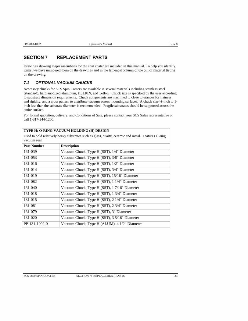
SECTION 7 REPLACEMENT PARTS
Drawings showing major assemblies for the spin coater are included in this manual. To help you identify
items, we have numbered them on the drawings and in the left-most column of the bill of material listing
on the drawing.
7.1 OPTIONAL VACUUM CHUCKS
Accessory chucks for SCS Spin Coaters are available in several materials including stainless steel
(standard), hard anodized aluminum, DELRIN, and Teflon. Chuck size is specified by the user according
to substrate dimension requirements. Chuck components are machined to close tolerances for flatness
and rigidity, and a cross pattern to distribute vacuum across mounting surfaces. A chuck size ¼-inch to 1-
inch less than the substrate diameter is recommended. Fragile substrates should be supported across the
entire surface.
For formal quotation, delivery, and Conditions of Sale, please contact your SCS Sales representative or
call 1-317-244-1200.
TYPE H: O-RING VACUUM HOLDING (H) DESIGN
Used to hold relatively heavy substrates such as glass, quartz, ceramic and metal. Features O-ring
vacuum seal.
Part Number Description
131-039 Vacuum Chuck, Type H (SST), 1/4" Diameter
131-053 Vacuum Chuck, Type H (SST), 3/8" Diameter
131-016 Vacuum Chuck, Type H (SST), 1/2" Diameter
131-014 Vacuum Chuck, Type H (SST), 3/4" Diameter
131-019 Vacuum Chuck, Type H (SST), 15/16" Diameter
131-082 Vacuum Chuck, Type H (SST), 1 1/4" Diameter
131-040 Vacuum Chuck, Type H (SST), 1 7/16" Diameter
131-018 Vacuum Chuck, Type H (SST), 1 3/4" Diameter
131-015 Vacuum Chuck, Type H (SST), 2 1/4" Diameter
131-081 Vacuum Chuck, Type H (SST), 2 3/4" Diameter
131-079 Vacuum Chuck, Type H (SST), 3" Diameter
131-020 Vacuum Chuck, Type H (SST), 3 5/16" Diameter
PP-131-1002-0 Vacuum Chuck, Type H (ALUM), 4 1/2" Diameter
Rev 8 Operator’s Manual OM-813-1002
24 SECTION 7: REPLACEMENT PARTS SCS 6800 SPIN COATER
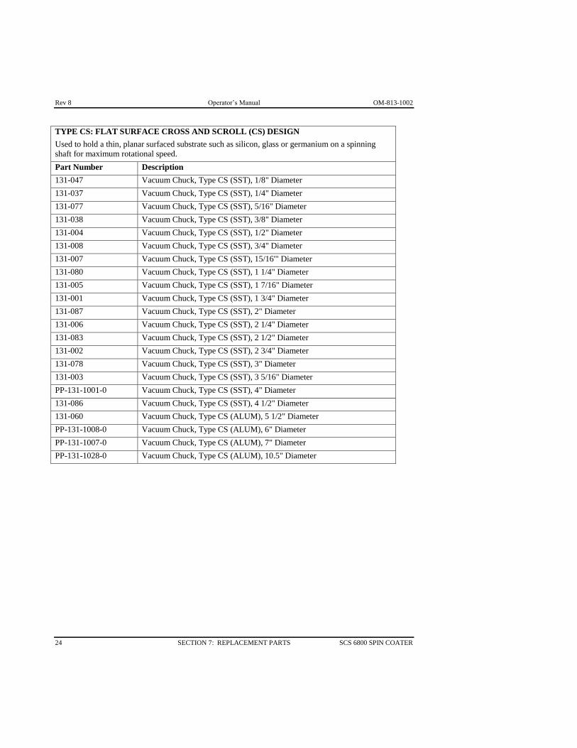
TYPE CS: FLAT SURFACE CROSS AND SCROLL (CS) DESIGN
Used to hold a thin, planar surfaced substrate such as silicon, glass or germanium on a spinning
shaft for maximum rotational speed.
Part Number Description
131-047 Vacuum Chuck, Type CS (SST), 1/8" Diameter
131-037 Vacuum Chuck, Type CS (SST), 1/4" Diameter
131-077 Vacuum Chuck, Type CS (SST), 5/16" Diameter
131-038 Vacuum Chuck, Type CS (SST), 3/8" Diameter
131-004 Vacuum Chuck, Type CS (SST), 1/2" Diameter
131-008 Vacuum Chuck, Type CS (SST), 3/4" Diameter
131-007 Vacuum Chuck, Type CS (SST), 15/16'" Diameter
131-080 Vacuum Chuck, Type CS (SST), 1 1/4" Diameter
131-005 Vacuum Chuck, Type CS (SST), 1 7/16" Diameter
131-001 Vacuum Chuck, Type CS (SST), 1 3/4" Diameter
131-087 Vacuum Chuck, Type CS (SST), 2" Diameter
131-006 Vacuum Chuck, Type CS (SST), 2 1/4" Diameter
131-083 Vacuum Chuck, Type CS (SST), 2 1/2" Diameter
131-002 Vacuum Chuck, Type CS (SST), 2 3/4" Diameter
131-078 Vacuum Chuck, Type CS (SST), 3" Diameter
131-003 Vacuum Chuck, Type CS (SST), 3 5/16" Diameter
PP-131-1001-0 Vacuum Chuck, Type CS (SST), 4" Diameter
131-086 Vacuum Chuck, Type CS (SST), 4 1/2" Diameter
131-060 Vacuum Chuck, Type CS (ALUM), 5 1/2" Diameter
PP-131-1008-0 Vacuum Chuck, Type CS (ALUM), 6" Diameter
PP-131-1007-0 Vacuum Chuck, Type CS (ALUM), 7" Diameter
PP-131-1028-0 Vacuum Chuck, Type CS (ALUM), 10.5" Diameter

OM-813-1002 Operator’s Manual Rev 8
SCS 6800 SPIN COATER SECTION 7: REPLACEMENT PARTS 25
TYPE L: O-RING VACUUM HOLDING CHUCK WITH
MECHANICAL LOCATING (L) FINGERS
Designed for heavy, large or unsymmetrical substrates. Guide fingers assist in positioning and
holding substrates. An O-ring seal is also provided.
Part Number Description
131-013 Vacuum Chuck, Type L (SST), 1 3/4" Diameter, Finger Size "A"
131-058 Vacuum Chuck, Type L (SST), 1 3/4" Diameter, Finger Size "B"
131-032 Vacuum Chuck, Type L (SST), 1 3/4" Diameter, Finger Size "C"
131-026 Vacuum Chuck, Type L (SST), 1 3/4" Diameter, Finger Size "D"
131-069 Vacuum Chuck, Type L (SST), 2 1/2" Diameter, Finger Size "__"
131-030 Vacuum Chuck, Type L (SST), 3 5/16" Diameter, Finger Size "E"
131-022 Vacuum Chuck, Type L (SST), 3 5/16" Diameter, Finger Size "F"
131-021 Vacuum Chuck, Type L (SST), 3 5/16" Diameter, Finger Size "G"
PP-131-1022-0 Vacuum Chuck, Type L (ALUM), 5 1/2" Diameter
131-012
Finger Size "A" to Fit Substrate Size 2" - 2 3/8" For Use with Vacuum
Chuck, Type L (SST), 1 3/4" Diameter
131-027
Finger Size "B" to Fit Substrate Size 2 3/8" - 2 3/4" For Use with
Vacuum Chuck, Type L (SST), 1 3/4" Diameter
131-028
Finger Size "C" to Fit Substrate Size 2 3/4" - 3 1/8" For Use with
Vacuum Chuck, Type L (SST), 1 3/4" Diameter
131-035
Finger Size "D" to Fit Substrate Size 3 1/8" - 3 1/2" For Use with
Vacuum Chuck, Type L (SST), 1 3/4" Diameter
131-059
Finger Size "E" to Fit Substrate Size 3 1/2" - 3 7/8" For Use with Vacuum
Chuck, Type L (SST), 3 5/16" Diameter
131-036
Finger Size "F" to Fit Substrate Size 3 7/8" - 4 1/4" For Use with Vacuum
Chuck, Type L (SST), 3 5/16" Diameter
131-023
Finger Size "G" to Fit Substrate Size 4 1/4" - 6" For Use with Vacuum
Chuck, Type L (SST), 3 5/16" Diameter
*Four Fingers Required per Chuck

Rev 8 Operator’s Manual OM-813-1002
26 SECTION 7: REPLACEMENT PARTS SCS 6800 SPIN COATER
OM-813-1002 Operator’s Manual Rev 8
SCS 6800 SPIN COATER SECTION 8: WARRANTY 27
SECTION 8 LIMITED WARRANTY POLICY
I. Subject to the limitations hereinafter set forth, SPECIALTY COATING SYSTEMS ("SCS")
warrants that all component parts manufactured by SCS are free from defects in materials and
workmanship for a period of twelve (12) months from the date of shipment. SCS will replace
materials for a period of twelve (12) months from the date of shipment, and provide labor, if
required, for a period of six (6) months from the date of shipment to correct warranty defects.
II. Components such as gauges and meters, controllers, pumps, motors and valves are warranted by
their respective manufacturers and these warranties are extended to the end user. Alcohol
solutions and D.I. columns are not warranted.
III. If, within the warranty period, any equipment or components manufactured by SCS shall prove to
SCS's satisfaction to be defective, such equipment or parts shall be replaced or repaired, at SCS's
option, at SCS's expense. Installation of replacement equipment or parts shall be at the
Purchaser's expense.
IV. The foregoing warranty shall be limited with respect to parts which are subject to wear or
chemical reactions or which have a variable life expectancy, including but not specifically limited
to, protective coatings, thermocouples, heaters, seals, o-rings, drive belts, relays, lamps and
bearings (but not including filters) to a period of ninety (90) days from the date of shipment. Test
cells are warranted for six (6) months from the date of shipment.
V. SCS's obligation hereunder shall be limited to repair or replacement, F.O.B. SCS's factory, and
shall be conditioned upon receipt of written notice of such defect within ten (10) days after its
discovery. Prior written approval is required, for return shipment of equipment or components to
SCS at SCS's expense.
VI. This warranty shall not apply to equipment or parts which have been repaired or altered by any
party other than SCS as, in SCS's judgment, adversely affects the same, or which shall be subject
to negligence, accident, damage or circumstances beyond SCS's control (including fire,
earthquake, flood or other acts of God), or improper installation, operation, maintenance, or
storage, or to other than normal use of service. Improper operation of equipment or any part
thereof shall include, without limitation, operation under loads, speeds, pressures or electrical
current characteristics, or with supplies not complying with SCS's specifications.
VII. SCS will not accept responsibility for repairs or the cost of any work done without specific
written SCS authorization.
VIII. This warranty does not apply to used or second-hand equipment, nor does it extend to any person
other than the original Purchaser.
Comment [RBT2]: Updated to include items from Instruments warranty. 1-6-2003
Rev 8 Operator’s Manual OM-813-1002
28 SECTION 8: WARRANTY SCS 6800 SPIN COATER
IX. This warranty does not apply to equipment which is broken or damaged in transit. In no event
shall SCS be responsible for any liability, loss or damage of such equipment delivered in good
order and condition to a carrier or carriers at any point of shipment.
X. This warranty shall not cover, and SCS shall not be liable for, losses of supplies or time, damages
to materials, or consequential damages of any nature, arising from or attributable to equipment
sold to the Purchaser by SCS. This warranty is strictly limited to the replacement or repair of the
equipment or parts purchased.
XI. SCS's liability to the Purchaser arising out of the supplying of this equipment or its use, whether
based on warranty, contract, or negligence, shall not in any case exceed the cost of correcting
defects in the equipment as herein provided, and upon expiration of the applicable warranty
period as aforesaid, all such liability shall terminate.
XII. EXCEPT AS OTHERWISE SET FORTH IN THIS LIMITED WARRANTY, THE
EQUIPMENT AND PARTS SOLD BY SCS TO PURCHASER ARE SOLD "AS IS" AND
"WHERE IS" AND "WITH ALL FAULTS," AND SCS DOES NOT MAKE AND SHALL NOT
BE DEEMED TO HAVE MADE, AND SCS HEREBY DISCLAIMS, ANY
REPRESENTATION OR WARRANTY, EXPRESSED OR IMPLIED, REGARDING THE
DESIGN, CONSTRUCTION OR CONDITION OF, OR THE QUALITY OF MATERIAL OR
WORKMANSHIP IN, THE EQUIPMENT OR PARTS, AND SCS MAKES NO WARRANTY
OF MERCHANTABILITY OR FITNESS OF THE EQUIPMENT OR PARTS FOR ANY
PARTICULAR PURPOSE.
SPECIALTY COATING SYSTEMS
7645 Woodland Drive
Indianapolis, IN 46278-2707
Telephone: 317-244-1200
Fax: 317-240-2073

OM-813-1002 Operator’s Manual Rev 8
SCS 6800 SPIN COATER SECTION 9: FORMS 29
SECTION 9 NEED ASSISTANCE?
TO EXPEDITE YOUR SERVICE REQUEST:
Please complete the following questionnaire, and have it readily available, before contacting
SCS for customer assistance. Providing all of the requested information will help to ensure the most
rapid response to a request for service when contacting us.
PLEASE NOTE: SCS requires all returns are accompanied by a Return Material
Authorization (RMA).Equipment:
Equipment Type/Model Serial Number
Specialty Coating Systems representative (if known)
__________________________________________________________.
IF FAXING A REQUEST, PLEASE INCLUDE THE FOLLOWING INFORMATION: Company Name: _____________________________________________
Contact Name: _____________________________________________
Position/Title: _____________________________________________
Phone: _____________________________________________
Email: _____________________________________________
Address: _____________________________________________
City: __________________ State:______ Zip:____________
CONTACT US:
CALL: (317) 244-1200 or (800) 356-8260
FAX: FAX (317) 240-2073
EMAIL: [email protected]
MAIL: Specialty Coating Systems
7645 Woodland Drive
Indianapolis, IN 46278-2707
NOTE: We hope that this manual meets all of your needs. If,
however, you notice an error, typo, omission, or organizational
problem, please send e-mail to

Rev 8 Operator’s Manual OM-813-1002
30 SECTION 9: FORMS SCS 6800 SPIN COATER

OM-813-1002 Operator’s Manual Rev 8
SCS 6800 SPIN COATER SECTION 10: TECHNICAL LITERATURE 31
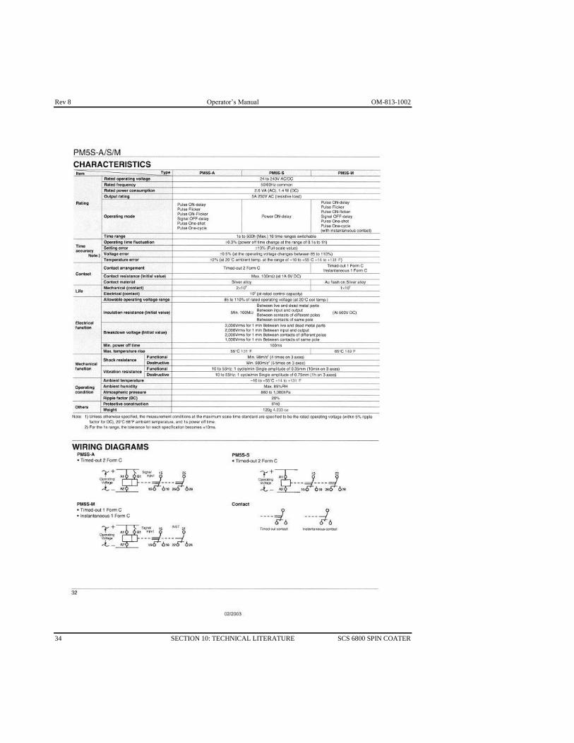
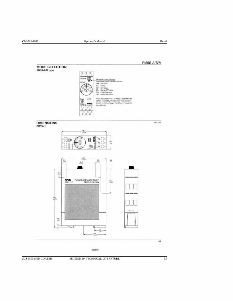
SECTION 10 TECHNICAL LITERATURE
TIMER NAIS PM5S
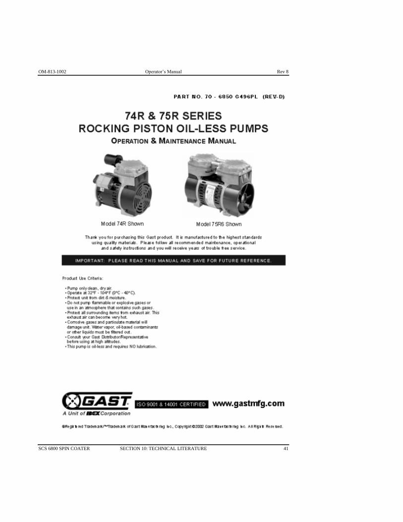
VACUUM PUMP GAST Series 23

Rev 8 Operator’s Manual OM-813-1002
32 SECTION 10: TECHNICAL LITERATURE SCS 6800 SPIN COATER

OM-813-1002 Operator’s Manual Rev 8
SCS 6800 SPIN COATER SECTION 10: TECHNICAL LITERATURE 33
Rev 8 Operator’s Manual OM-813-1002
34 SECTION 10: TECHNICAL LITERATURE SCS 6800 SPIN COATER
OM-813-1002 Operator’s Manual Rev 8
SCS 6800 SPIN COATER SECTION 10: TECHNICAL LITERATURE 35

Rev 8 Operator’s Manual OM-813-1002
36 SECTION 10: TECHNICAL LITERATURE SCS 6800 SPIN COATER

OM-813-1002 Operator’s Manual Rev 8
SCS 6800 SPIN COATER SECTION 10: TECHNICAL LITERATURE 37

Rev 8 Operator’s Manual OM-813-1002
38 SECTION 10: TECHNICAL LITERATURE SCS 6800 SPIN COATER

OM-813-1002 Operator’s Manual Rev 8
SCS 6800 SPIN COATER SECTION 10: TECHNICAL LITERATURE 39

Rev 8 Operator’s Manual OM-813-1002
40 SECTION 10: TECHNICAL LITERATURE SCS 6800 SPIN COATER
OM-813-1002 Operator’s Manual Rev 8
SCS 6800 SPIN COATER SECTION 10: TECHNICAL LITERATURE 41

Rev 8 Operator’s Manual OM-813-1002
42 SECTION 10: TECHNICAL LITERATURE SCS 6800 SPIN COATER

OM-813-1002 Operator’s Manual Rev 8
SCS 6800 SPIN COATER SECTION 10: TECHNICAL LITERATURE 43

Rev 8 Operator’s Manual OM-813-1002
44 SECTION 10: TECHNICAL LITERATURE SCS 6800 SPIN COATER

OM-813-1002 Operator’s Manual Rev 8
SCS 6800 SPIN COATER SECTION 10: TECHNICAL LITERATURE 45

Rev 8 Operator’s Manual OM-813-1002
46 SECTION 10: TECHNICAL LITERATURE SCS 6800 SPIN COATER

OM-813-1002 Operator’s Manual Rev 8
SCS 6800 SPIN COATER SECTION 10: TECHNICAL LITERATURE 47

Rev 8 Operator’s Manual OM-813-1002
48 SECTION 10: TECHNICAL LITERATURE SCS 6800 SPIN COATER

OM-813-1002 Operator’s Manual Rev 8
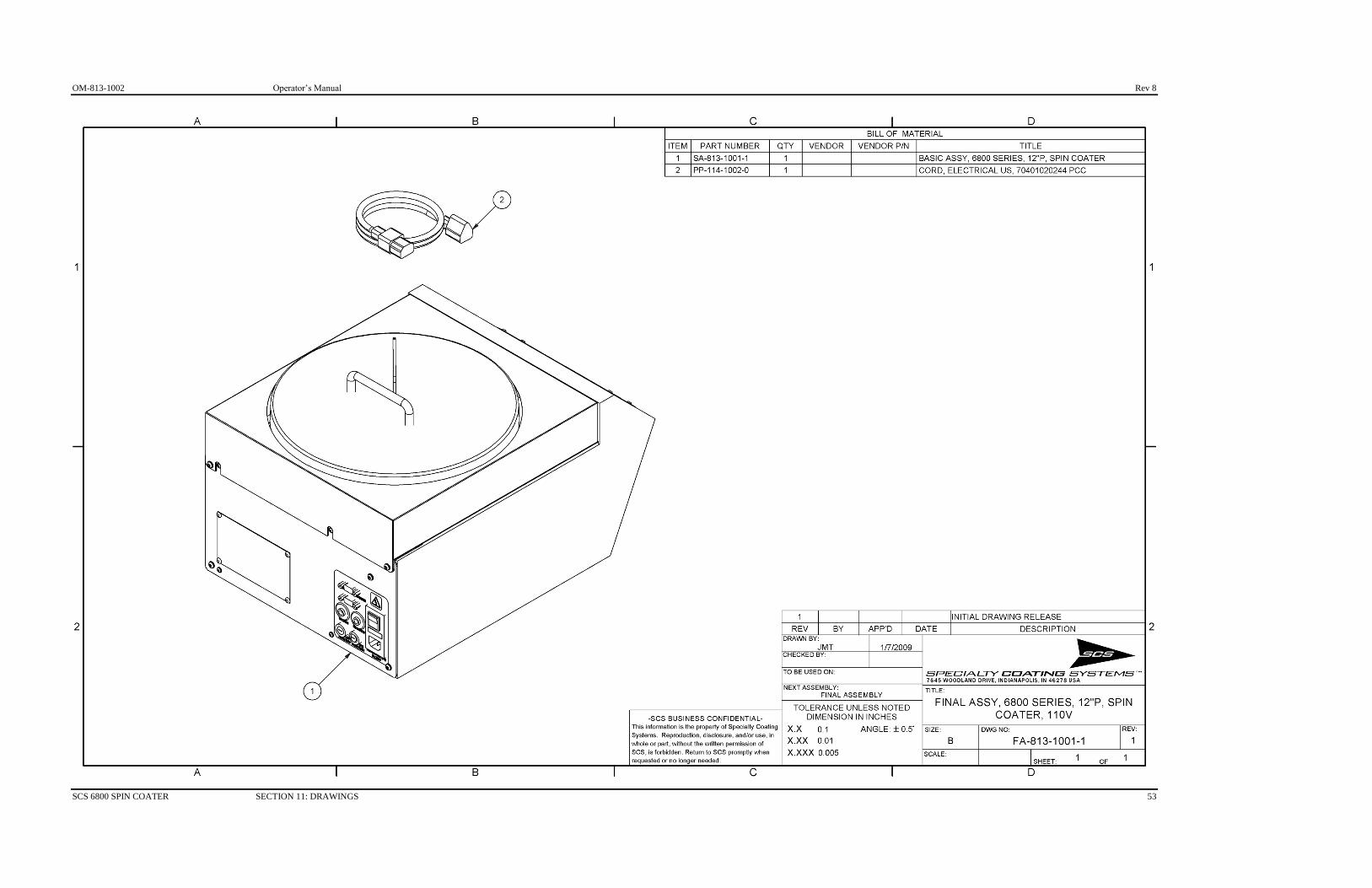
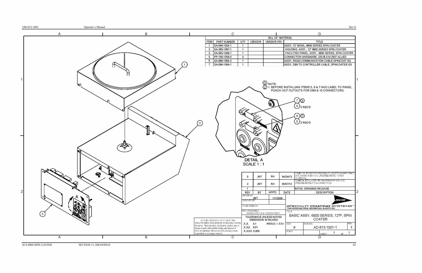
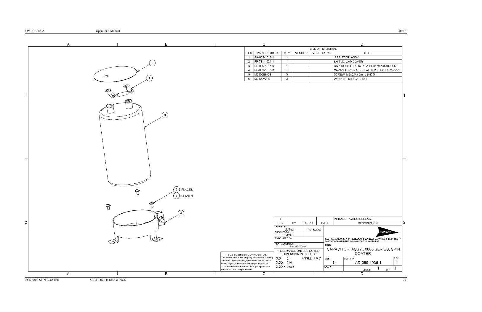
SCS 6800 SPIN COATER SECTION 11: DRAWINGS 49
SECTION 11 DRAWINGS
FA-813-1000-1 Final Assembly 8” Non Programmable 110 Volts
FA-813-1001-1 Final Assembly 12” Programmable 110 Volts
FA-813-1003-1 Final Assembly 8” Non Programmable 220 Volts
FA-813-1004-1 Final Assembly 8” Programmable 110 Volts
FA-813-1005-1 Final Assembly 8” Programmable 220 Volts
FA-813-1006-1 Final Assembly 12” Programmable 220 Volts
AD-813-1000-1 Basic Assembly 8” Non Programmable
AD-813-1001-1 Basic Assembly 12” Programmable
AD-813-1004-1 Basic Assembly 8” Programmable
AD-046-1022-1 8” Bowl Assembly
AD-046-1024-1 12” Bowl Assembly
AD-385-1081-1 Housing Assembly 8”
AD-385-1087-1 Housing Assembly 12”
AD-089-1035-1 Capacitor Assembly
AD-662-1012-1 Resistor Assembly
AD-490-1042-1 Motor Assembly
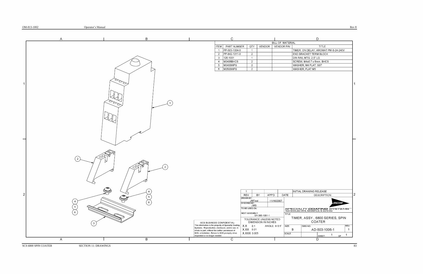
AD-503-1006-1 Timer Assembly
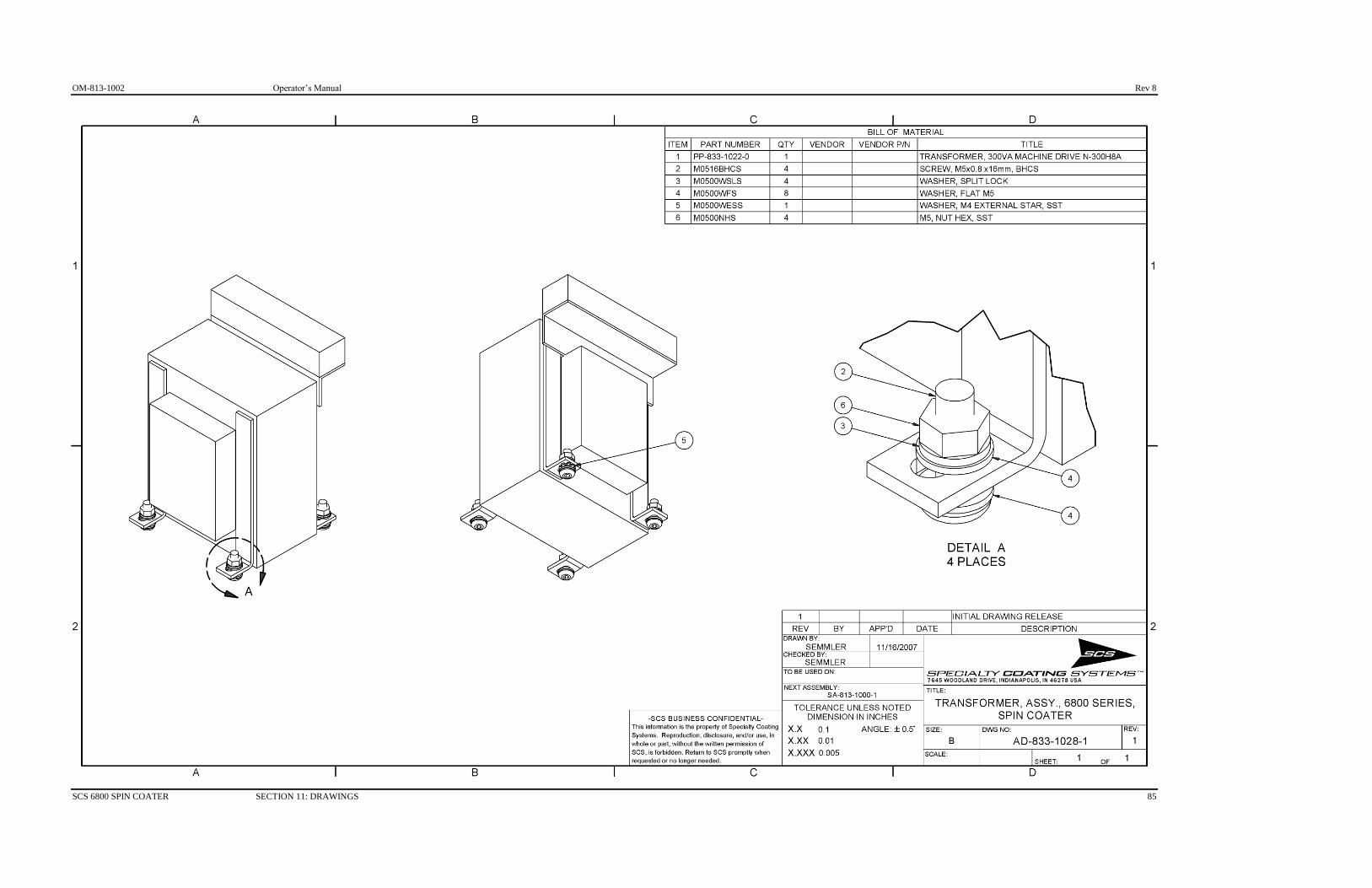
AD-833-1028-1 Transformer Assembly
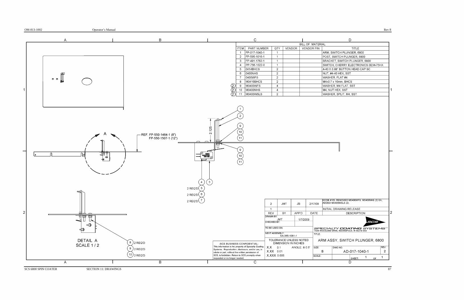
AD-017-1040-1 Lid Closed Switch Assembly
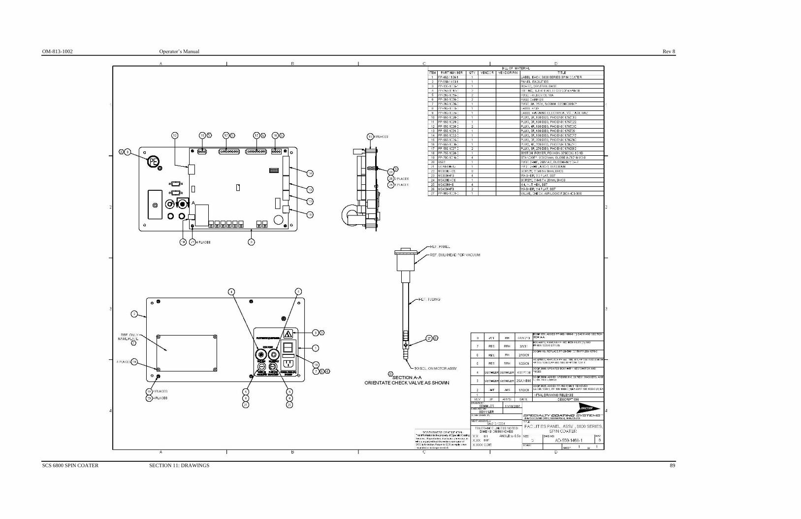
AD-550-1468-1 Facilities Panel Assembly
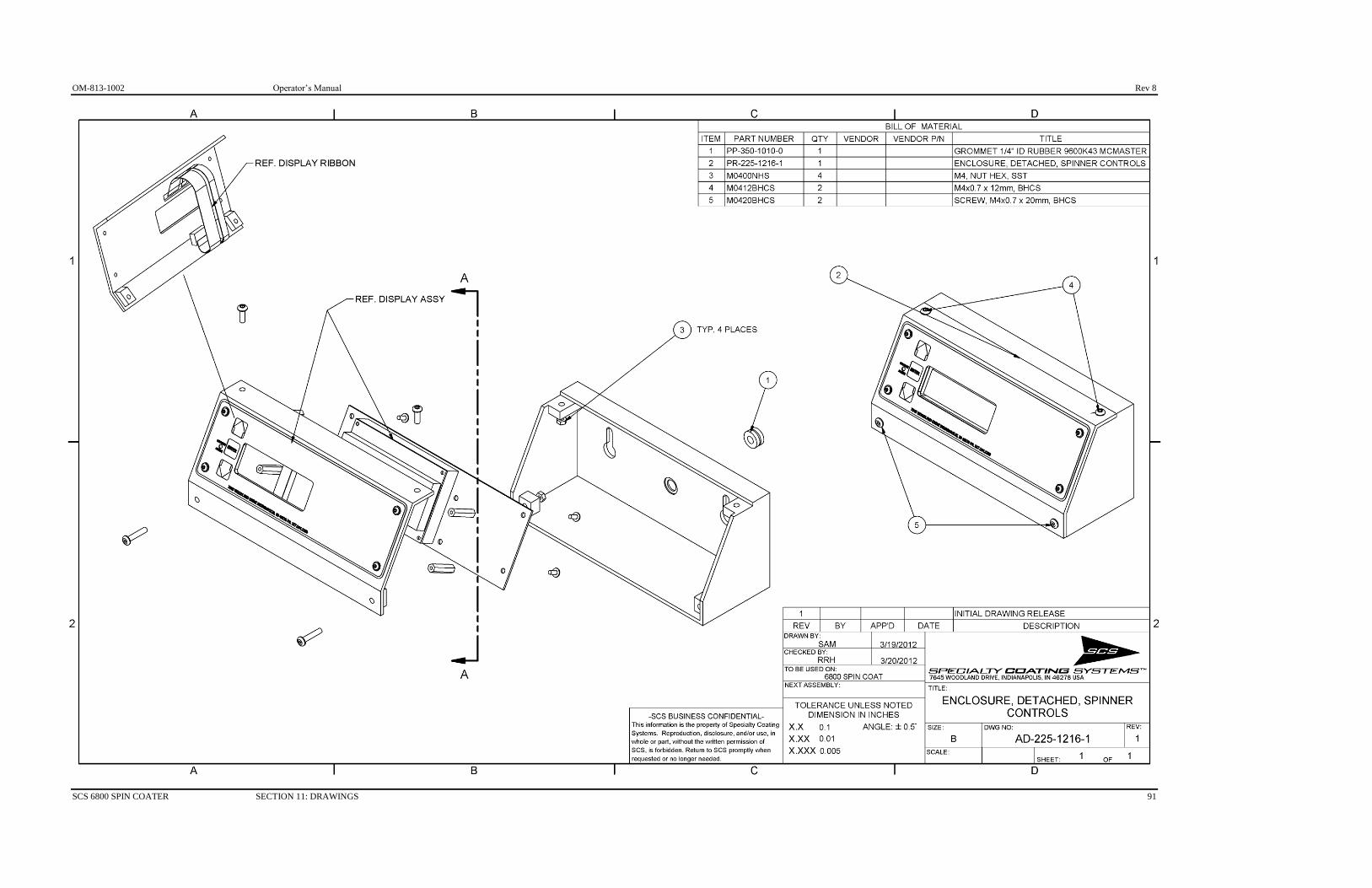
AD-225-1216-1 Detached Spinner Controls
ES-813-1000-1 Electrical Schematic
PS-812-1000-1 Pneumatic Schematic

Rev 8 Operator’s Manual OM-813-1002
50 SECTION 11: DRAWINGS SCS 6800 SPIN COATER

OM-813-1002 Operator’s Manual Rev 8
SCS 6800 SPIN COATER SECTION 11: DRAWINGS 51

Rev 8 Operator’s Manual OM-813-1002
52 SECTION 11: DRAWINGS SCS 6800 SPIN COATER
OM-813-1002 Operator’s Manual Rev 8
SCS 6800 SPIN COATER SECTION 11: DRAWINGS 53

Rev 8 Operator’s Manual OM-813-1002
54 SECTION 11: DRAWINGS SCS 6800 SPIN COATER

OM-813-1002 Operator’s Manual Rev 8
SCS 6800 SPIN COATER SECTION 11: DRAWINGS 55

Rev 8 Operator’s Manual OM-813-1002
56 SECTION 11: DRAWINGS SCS 6800 SPIN COATER

OM-813-1002 Operator’s Manual Rev 8
SCS 6800 SPIN COATER SECTION 11: DRAWINGS 57

Rev 8 Operator’s Manual OM-813-1002
58 SECTION 11: DRAWINGS SCS 6800 SPIN COATER

OM-813-1002 Operator’s Manual Rev 8
SCS 6800 SPIN COATER SECTION 11: DRAWINGS 59

Rev 8 Operator’s Manual OM-813-1002
60 SECTION 11: DRAWINGS SCS 6800 SPIN COATER

OM-813-1002 Operator’s Manual Rev 8
SCS 6800 SPIN COATER SECTION 11: DRAWINGS 61

Rev 8 Operator’s Manual OM-813-1002
62 SECTION 11: DRAWINGS SCS 6800 SPIN COATER

OM-813-1002 Operator’s Manual Rev 8
SCS 6800 SPIN COATER SECTION 11: DRAWINGS 63

Rev 8 Operator’s Manual OM-813-1002
64 SECTION 11: DRAWINGS SCS 6800 SPIN COATER
OM-813-1002 Operator’s Manual Rev 8
SCS 6800 SPIN COATER SECTION 11: DRAWINGS 65

Rev 8 Operator’s Manual OM-813-1002
66 SECTION 11: DRAWINGS SCS 6800 SPIN COATER

OM-813-1002 Operator’s Manual Rev 8
SCS 6800 SPIN COATER SECTION 11: DRAWINGS 67

Rev 8 Operator’s Manual OM-813-1002
68 SECTION 11: DRAWINGS SCS 6800 SPIN COATER

OM-813-1002 Operator’s Manual Rev 8
SCS 6800 SPIN COATER SECTION 11: DRAWINGS 69

Rev 8 Operator’s Manual OM-813-1002
70 SECTION 11: DRAWINGS SCS 6800 SPIN COATER

OM-813-1002 Operator’s Manual Rev 8
SCS 6800 SPIN COATER SECTION 11: DRAWINGS 71

Rev 8 Operator’s Manual OM-813-1002
72 SECTION 11: DRAWINGS SCS 6800 SPIN COATER

OM-813-1002 Operator’s Manual Rev 8
SCS 6800 SPIN COATER SECTION 11: DRAWINGS 73

Rev 8 Operator’s Manual OM-813-1002
74 SECTION 11: DRAWINGS SCS 6800 SPIN COATER

OM-813-1002 Operator’s Manual Rev 8
SCS 6800 SPIN COATER SECTION 11: DRAWINGS 75

Rev 8 Operator’s Manual OM-813-1002
76 SECTION 11: DRAWINGS SCS 6800 SPIN COATER
OM-813-1002 Operator’s Manual Rev 8
SCS 6800 SPIN COATER SECTION 11: DRAWINGS 77

Rev 8 Operator’s Manual OM-813-1002
78 SECTION 11: DRAWINGS SCS 6800 SPIN COATER

OM-813-1002 Operator’s Manual Rev 8
SCS 6800 SPIN COATER SECTION 11: DRAWINGS 79

Rev 8 Operator’s Manual OM-813-1002
80 SECTION 11: DRAWINGS SCS 6800 SPIN COATER

OM-813-1002 Operator’s Manual Rev 8
SCS 6800 SPIN COATER SECTION 11: DRAWINGS 81

Rev 8 Operator’s Manual OM-813-1002
82 SECTION 11: DRAWINGS SCS 6800 SPIN COATER
OM-813-1002 Operator’s Manual Rev 8
SCS 6800 SPIN COATER SECTION 11: DRAWINGS 83

Rev 8 Operator’s Manual OM-813-1002
84 SECTION 11: DRAWINGS SCS 6800 SPIN COATER
OM-813-1002 Operator’s Manual Rev 8
SCS 6800 SPIN COATER SECTION 11: DRAWINGS 85

Rev 8 Operator’s Manual OM-813-1002
86 SECTION 11: DRAWINGS SCS 6800 SPIN COATER
OM-813-1002 Operator’s Manual Rev 8
SCS 6800 SPIN COATER SECTION 11: DRAWINGS 87

Rev 8 Operator’s Manual OM-813-1002
88 SECTION 11: DRAWINGS SCS 6800 SPIN COATER
OM-813-1002 Operator’s Manual Rev 8
SCS 6800 SPIN COATER SECTION 11: DRAWINGS 89

Rev 8 Operator’s Manual OM-813-1002
90 SECTION 11: DRAWINGS SCS 6800 SPIN COATER
OM-813-1002 Operator’s Manual Rev 8
SCS 6800 SPIN COATER SECTION 11: DRAWINGS 91

Rev 8 Operator’s Manual OM-813-1002
92 SECTION 11: DRAWINGS SCS 6800 SPIN COATER