Embed Size (px)
Citation preview
Service
Service Department. Technical Information WSK 01 720 CF
No.
68
Fitting instructionQ5 2009
BodyOffroad aesthetic package retrofit solutionEdition 1.09
Service
All rights reserved.No reproduction without prior agreement from publisher.
Printed in GermanyCopyright © 2009 Audi AG, Ingolstadt
Contents
1 General notes .......................................................................................
2 Parts required .......................................................................................
3 Fitting the front bumper ............................................................................3.1 Removing the lock carrier cover ...................................................................3.2 Removing the bumper cover .......................................................................3.3 Mount number plate carrier - country variants (USA, Japan, China) ............................3.4 Removing/installing and replacing the right-hand air intake grille - models with ACC ..........3.5 Install the radiator protection grille striker plate -8R0 853 692 A 3BJ- - models with diesel
engine ...............................................................................................3.6 Installing the front bumper cover ..................................................................
4 Replacing the rear spoiler ..........................................................................4.1 Assembly overview of luggage compartment floor ...............................................4.2 Removing front luggage compartment floor ......................................................4.3 Vehicles with support rails Removing support rails ..............................................4.4 Vehicles with fixed fastening rings - Removing the fastening rings .............................4.5 Removing trim cover for door ......................................................................4.6 Removing rear retainer .............................................................................4.7 Assembly overview of rear end panelling .........................................................4.8 Removing the rear cross panel trim ...............................................................4.9 Assembly overview of luggage compartment side trim ..........................................4.10 Removing the suit hanger ..........................................................................4.11 Removing the luggage compartment side trim ....................................................4.12 Assembly overview of rear bumper cover ........................................................4.13 Removing the rear bumper cover ..................................................................4.14 Removing/installing and replacing the spoiler .....................................................4.15 Other tightening torques ...........................................................................
5 Mounting trim covers for doors and wheel arch trims ...........................................5.1 Mounting the wing panel cover ....................................................................5.2 Fitting trim covers for doors .......................................................................5.3 Mounting the front wheel housing covers ........................................................5.4 Mounting the rear wheel housing covers .........................................................
6 Appendices: Certificates, expert evaluations .....................................................
1
2
55678
88
9101010111111121313141415161818
1919202123
25
Q5 2009No. 68, Body, Edition 1.09
1 General notes 1
1 General notesPlease read and apply these WARNING, Caution and Note descriptions before carrying out maintenance or repair work.
. Text with this symbol contains additional useful
information.
. A Note symbol also contains special and additional notes
on repair measures and associated information.
Audi AG shall not accept responsibility in the event of failure
to comply with these assembly instructions.
WARNING!
. Text with this symbol contains information concerning
your safety and how you can reduce the risk of serious
and fatal injuries.
. Pay special attention to the WARNING symbol. Ensure
that you read the relevant texts thoroughly.
Caution!
. Text with this symbol contains information on how to
avoid vehicle damage.
. A Caution symbol indicates that failure to follow
information can lead to vehicle damage. (E.g. ensure
that the ignition has been switched off before the vehicle
battery is connected, otherwise the engine control unit
could be damaged.)
Caution!
The offroad aesthetic package retrofit solution should only be
fitted by a qualified workshop.
Special tools are required for assembly. Improper installation
can cause damage to the vehicle or the add-on components.
Note
Q5 2009
No. 68, Body, Edition 1.09
2 Parts required2
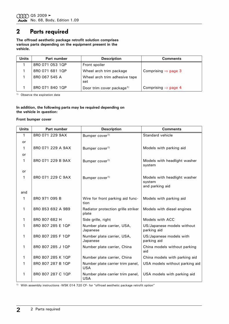
2 Parts requiredThe offroad aesthetic package retrofit solution comprises
various parts depending on the equipment present in the
vehicle.
In addition, the following parts may be required depending on
the vehicle in question:
Front bumper cover
Units Part number Description Comments
1 8R0 071 053 1QP Front spoiler
1 8R0 071 681 1QP Wheel arch trim package Comprising page 3
1 8R0 067 545 A Wheel arch trim adhesive tape
set
1 8R0 071 840 1QP Door trim cover package1)
1) Observe the expiration date
Comprising page 4
Units Part number Description Comments
1 8R0 071 229 9AX Bumper cover1)
1) With assembly instructions -WSK 014 720 CF- for “offroad aesthetic package retrofit option”
Standard vehicle
or
1 8R0 071 229 A 9AX Bumper cover1) Models with parking aid
or
1 8R0 071 229 B 9AX Bumper cover1) Models with headlight washer
system
or
1 8R0 071 229 C 9AX Bumper cover1) Models with headlight washer
system
and parking aid
and
1 8R0 971 095 B Wire for front parking aid func-
tion
Models with parking aid
1 8R0 853 692 A 9B9 Radiator protection grille striker
plate
Models with diesel engines
1 8R0 807 682 H Side grille, right Models with ACC
1 8R0 807 285 E 1QP Number plate carrier, USA,
Japanese
US/Japanese models without
parking aid
1 8R0 807 285 F 1QP Number plate carrier, USA,
Japanese
US/Japanese models with
parking aid
1 8R0 807 285 J 1QP Number plate carrier, China China models without parking
aid
1 8R0 807 285 K 1QP Number plate carrier, China China models with parking aid
1 8R0 807 287 B 1QP Number plate carrier trim panel,
USA
USA models without parking aid
1 8R0 807 287 C 1QP Number plate carrier trim panel,
USA
USA models with parking aid
Q5 2009
No. 68, Body, Edition 1.09
2 Parts required 3
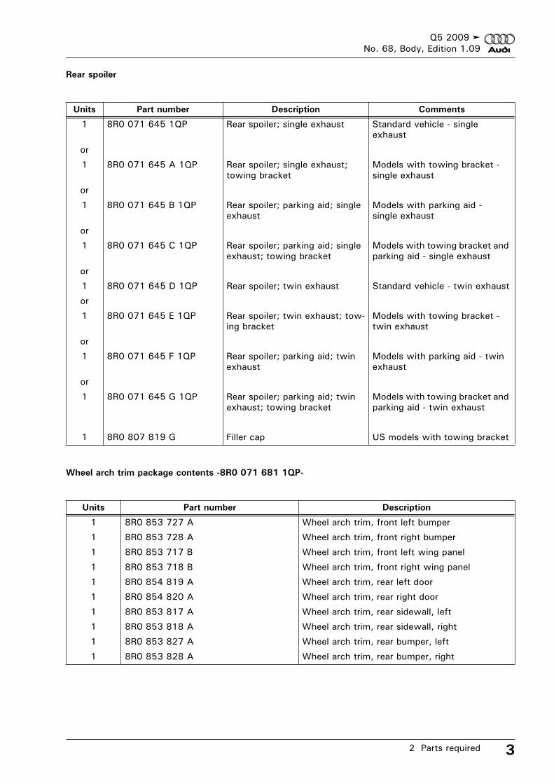
Rear spoiler
Wheel arch trim package contents -8R0 071 681 1QP-
Units Part number Description Comments
1 8R0 071 645 1QP Rear spoiler; single exhaust Standard vehicle - single
exhaust
or
1 8R0 071 645 A 1QP Rear spoiler; single exhaust;
towing bracket
Models with towing bracket -
single exhaust
or
1 8R0 071 645 B 1QP Rear spoiler; parking aid; single
exhaust
Models with parking aid -
single exhaust
or
1 8R0 071 645 C 1QP Rear spoiler; parking aid; single
exhaust; towing bracket
Models with towing bracket and
parking aid - single exhaust
or
1 8R0 071 645 D 1QP Rear spoiler; twin exhaust Standard vehicle - twin exhaust
or
1 8R0 071 645 E 1QP Rear spoiler; twin exhaust; tow-
ing bracket
Models with towing bracket -
twin exhaust
or
1 8R0 071 645 F 1QP Rear spoiler; parking aid; twin
exhaust
Models with parking aid - twin
exhaust
or
1 8R0 071 645 G 1QP Rear spoiler; parking aid; twin
exhaust; towing bracket
Models with towing bracket and
parking aid - twin exhaust
1 8R0 807 819 G Filler cap US models with towing bracket
Units Part number Description
1 8R0 853 727 A Wheel arch trim, front left bumper
1 8R0 853 728 A Wheel arch trim, front right bumper
1 8R0 853 717 B Wheel arch trim, front left wing panel
1 8R0 853 718 B Wheel arch trim, front right wing panel
1 8R0 854 819 A Wheel arch trim, rear left door
1 8R0 854 820 A Wheel arch trim, rear right door
1 8R0 853 817 A Wheel arch trim, rear sidewall, left
1 8R0 853 818 A Wheel arch trim, rear sidewall, right
1 8R0 853 827 A Wheel arch trim, rear bumper, left
1 8R0 853 828 A Wheel arch trim, rear bumper, right
Q5 2009
No. 68, Body, Edition 1.09
2 Parts required4
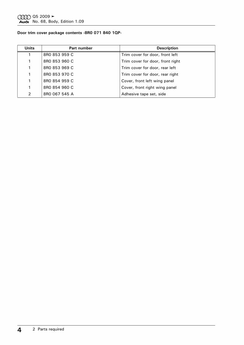
Door trim cover package contents -8R0 071 840 1QP-
Units Part number Description
1 8R0 853 959 C Trim cover for door, front left
1 8R0 853 960 C Trim cover for door, front right
1 8R0 853 969 C Trim cover for door, rear left
1 8R0 853 970 C Trim cover for door, rear right
1 8R0 854 959 C Cover, front left wing panel
1 8R0 854 960 C Cover, front right wing panel
2 8R0 067 545 A Adhesive tape set, side
Q5 2009No. 68, Body, Edition 1.09
3 Fitting the front bumper 5
3 Fitting the front bumper– Paint the front bumper.
Add-on components must always be painted in accordance
with the “Audi Paintwork Guideline”.
– Disconnect the vehicle battery earth wire Rep. Gr. 27.
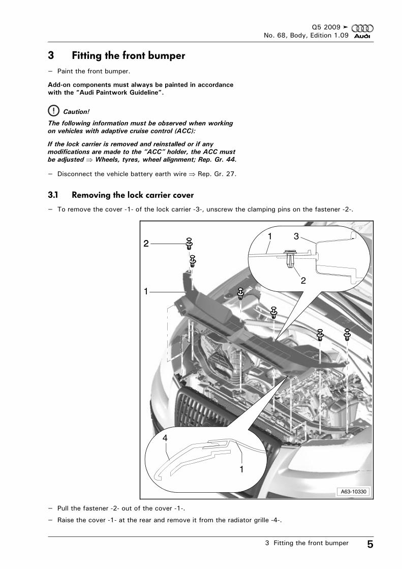
3.1 Removing the lock carrier cover
– To remove the cover -1- of the lock carrier -3-, unscrew the clamping pins on the fastener -2-.
– Pull the fastener -2- out of the cover -1-.
– Raise the cover -1- at the rear and remove it from the radiator grille -4-.
Caution!
The following information must be observed when working
on vehicles with adaptive cruise control (ACC):
If the lock carrier is removed and reinstalled or if any
modifications are made to the “ACC” holder, the ACC must
be adjusted Wheels, tyres, wheel alignment; Rep. Gr. 44.
1
A63-10330
221
2
3
1
4
Q5 2009No. 68, Body, Edition 1.09
3 Fitting the front bumper6
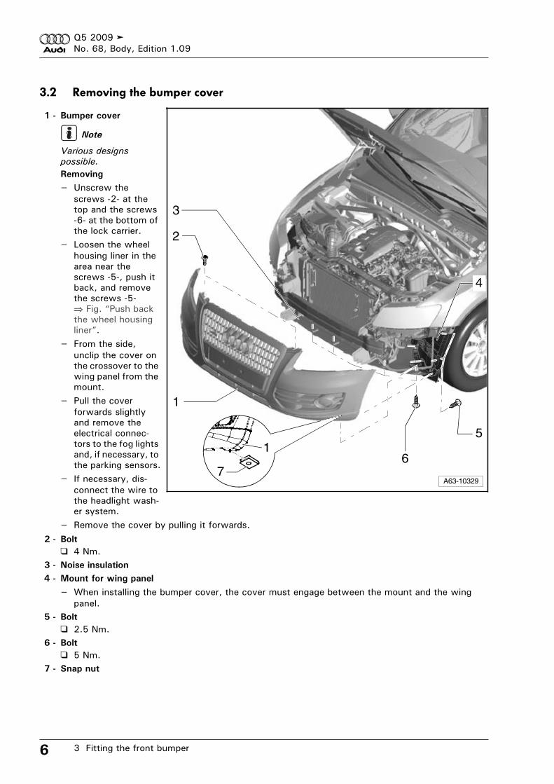
3.2 Removing the bumper cover
1 - Bumper cover
Various designs
possible.
Removing
– Unscrew the screws -2- at the top and the screws -6- at the bottom of the lock carrier.
– Loosen the wheel housing liner in the area near the screws -5-, push it back, and remove the screws -5-
Fig. “Push back the wheel housing liner”.
– From the side, unclip the cover on the crossover to the wing panel from the mount.
– Pull the cover forwards slightly and remove the electrical connec-tors to the fog lights and, if necessary, to the parking sensors.
– If necessary, dis-connect the wire to the headlight wash-er system.
– Remove the cover by pulling it forwards.
2 - Bolt
4 Nm.3 - Noise insulation
4 - Mount for wing panel
– When installing the bumper cover, the cover must engage between the mount and the wing panel.
5 - Bolt
2.5 Nm.6 - Bolt
5 Nm.7 - Snap nut
A63-10329
1
3
4
51
7
2
6
Note
Q5 2009No. 68, Body, Edition 1.09
3 Fitting the front bumper 7
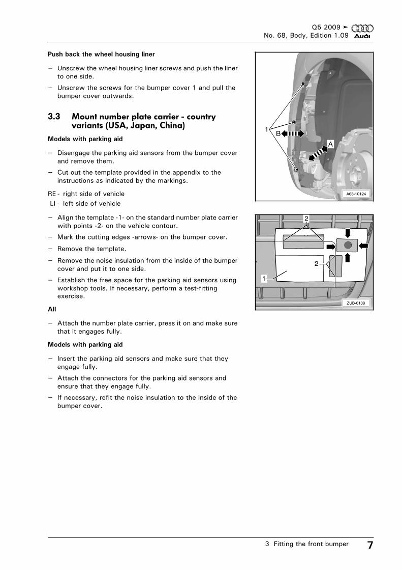
Push back the wheel housing liner
– Unscrew the wheel housing liner screws and push the liner to one side.
– Unscrew the screws for the bumper cover 1 and pull the bumper cover outwards.
3.3 Mount number plate carrier - country variants (USA, Japan, China)
Models with parking aid
– Disengage the parking aid sensors from the bumper cover and remove them.
– Cut out the template provided in the appendix to the instructions as indicated by the markings.
RE - right side of vehicleLI - left side of vehicle
– Align the template -1- on the standard number plate carrier with points -2- on the vehicle contour.
– Mark the cutting edges -arrows- on the bumper cover.
– Remove the template.
– Remove the noise insulation from the inside of the bumper cover and put it to one side.
– Establish the free space for the parking aid sensors using workshop tools. If necessary, perform a test-fitting exercise.
All
– Attach the number plate carrier, press it on and make sure that it engages fully.
Models with parking aid
– Insert the parking aid sensors and make sure that they engage fully.
– Attach the connectors for the parking aid sensors and ensure that they engage fully.
– If necessary, refit the noise insulation to the inside of the bumper cover.
A63-10124
1
A
B
ZUB-0138
2
1
2
Q5 2009No. 68, Body, Edition 1.09
3 Fitting the front bumper8
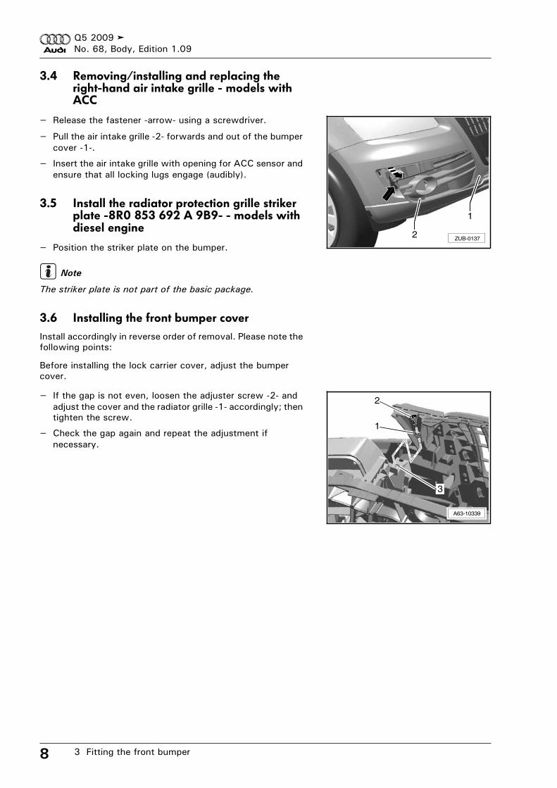
3.4 Removing/installing and replacing the right-hand air intake grille - models with ACC
– Release the fastener -arrow- using a screwdriver.
– Pull the air intake grille -2- forwards and out of the bumper cover -1-.
– Insert the air intake grille with opening for ACC sensor and ensure that all locking lugs engage (audibly).
3.5 Install the radiator protection grille striker plate -8R0 853 692 A 9B9- - models with diesel engine
– Position the striker plate on the bumper.
The striker plate is not part of the basic package.
3.6 Installing the front bumper coverInstall accordingly in reverse order of removal. Please note the following points:
Before installing the lock carrier cover, adjust the bumper cover.
– If the gap is not even, loosen the adjuster screw -2- and adjust the cover and the radiator grille -1- accordingly; then tighten the screw.
– Check the gap again and repeat the adjustment if necessary.
ZUB-0137
1
2
Note
3
A63-10339
2
1
Q5 2009No. 68, Body, Edition 1.09
4 Replacing the rear spoiler 9
4 Replacing the rear spoiler
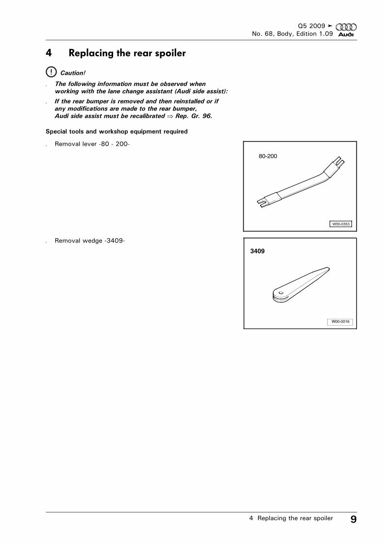
Special tools and workshop equipment required
. Removal lever -80 - 200-
. Removal wedge -3409-
Caution!
. The following information must be observed when
working with the lane change assistant (Audi side assist):
. If the rear bumper is removed and then reinstalled or if
any modifications are made to the rear bumper,
Audi side assist must be recalibrated Rep. Gr. 96.
80-200
Q5 2009No. 68, Body, Edition 1.09
4 Replacing the rear spoiler10
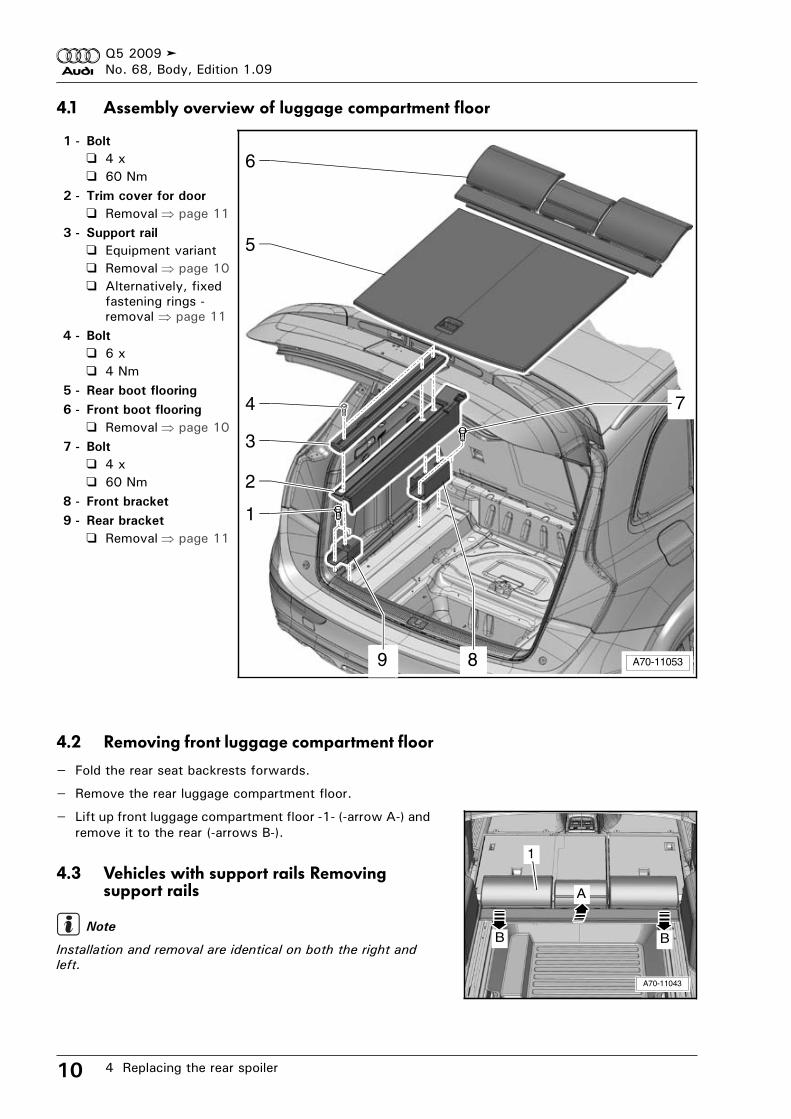
4.1 Assembly overview of luggage compartment floor
1 - Bolt
4 x60 Nm
2 - Trim cover for door
Removal page 113 - Support rail
Equipment variantRemoval page 10Alternatively, fixed fastening rings - removal page 11
4 - Bolt
6 x4 Nm
5 - Rear boot flooring
6 - Front boot flooring
Removal page 107 - Bolt
4 x60 Nm
8 - Front bracket
9 - Rear bracket
Removal page 11
4.2 Removing front luggage compartment floor
– Fold the rear seat backrests forwards.
– Remove the rear luggage compartment floor.
– Lift up front luggage compartment floor -1- (-arrow A-) and remove it to the rear (-arrows B-).
4.3 Vehicles with support rails Removing support rails
Installation and removal are identical on both the right and
left.
4
A70-11053
1
2
3
5
6
7
89
A70-11043
A
B
1
BNote
Q5 2009No. 68, Body, Edition 1.09
4 Replacing the rear spoiler 11
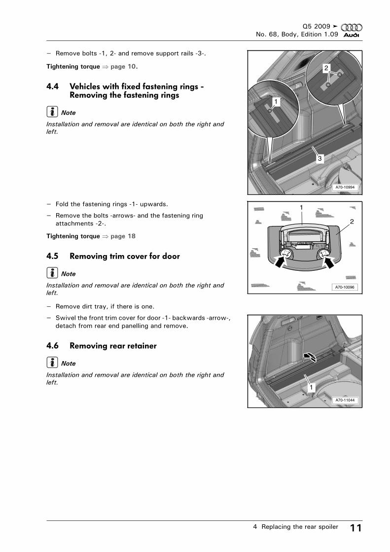
– Remove bolts -1, 2- and remove support rails -3-.
Tightening torque page 10.
4.4 Vehicles with fixed fastening rings - Removing the fastening rings
Installation and removal are identical on both the right and
left.
– Fold the fastening rings -1- upwards.
– Remove the bolts -arrows- and the fastening ring attachments -2-.
Tightening torque page 18
4.5 Removing trim cover for door
Installation and removal are identical on both the right and
left.
– Remove dirt tray, if there is one.
– Swivel the front trim cover for door -1- backwards -arrow-, detach from rear end panelling and remove.
4.6 Removing rear retainer
Installation and removal are identical on both the right and
left.
1
A70-10994
3
2
Note
A70-10096
1
2
Note
A70-11044
1
Note
Q5 2009No. 68, Body, Edition 1.09
4 Replacing the rear spoiler12
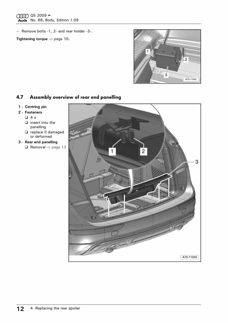
– Remove bolts -1, 2- and rear holder -3-.
Tightening torque page 10.
4.7 Assembly overview of rear end panelling
1 - Centring pin
2 - Fasteners
4 xinsert into the panellingreplace if damaged or deformed
3 - Rear end panelling
Removal page 13
A70-11042
1
2
3
A70-11049
1
3
2
Q5 2009No. 68, Body, Edition 1.09
4 Replacing the rear spoiler 13
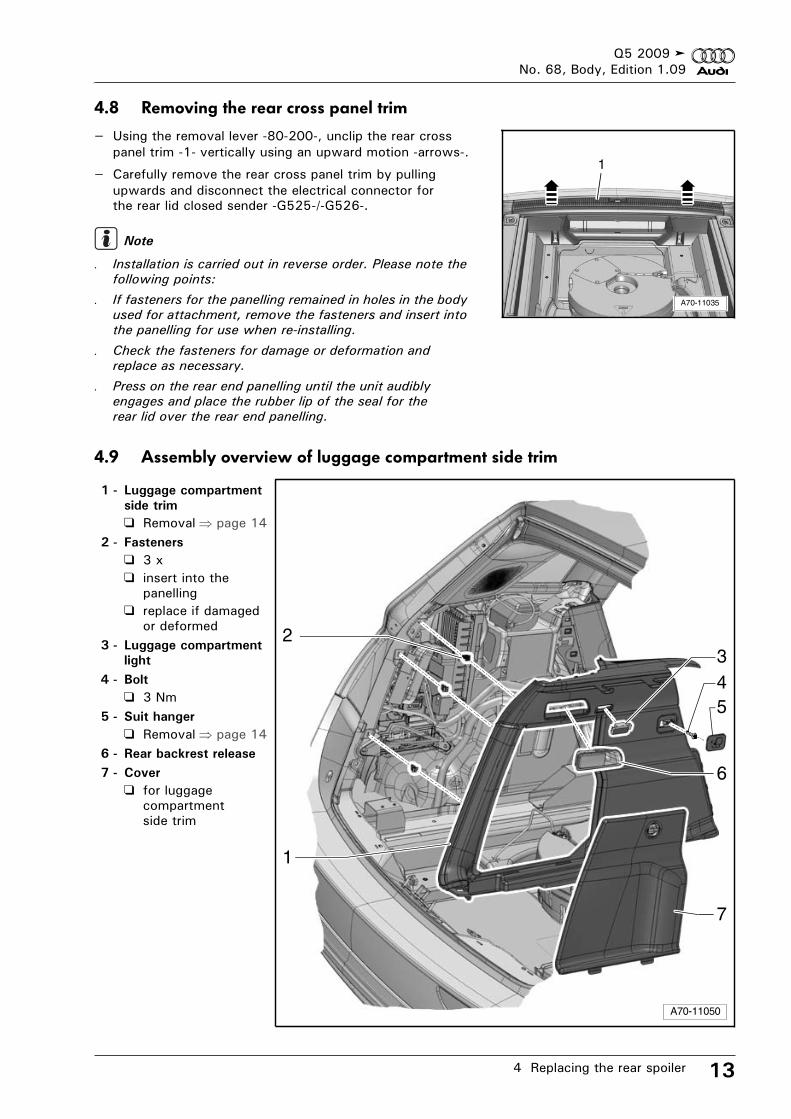
4.8 Removing the rear cross panel trim
– Using the removal lever -80-200-, unclip the rear cross panel trim -1- vertically using an upward motion -arrows-.
– Carefully remove the rear cross panel trim by pulling upwards and disconnect the electrical connector for the rear lid closed sender -G525-/-G526-.
. Installation is carried out in reverse order. Please note the
following points:
. If fasteners for the panelling remained in holes in the body
used for attachment, remove the fasteners and insert into
the panelling for use when re-installing.
. Check the fasteners for damage or deformation and
replace as necessary.
. Press on the rear end panelling until the unit audibly
engages and place the rubber lip of the seal for the
rear lid over the rear end panelling.
4.9 Assembly overview of luggage compartment side trim
1 - Luggage compartment
side trim
Removal page 142 - Fasteners
3 xinsert into the panellingreplace if damaged or deformed
3 - Luggage compartment
light
4 - Bolt
3 Nm5 - Suit hanger
Removal page 146 - Rear backrest release
7 - Cover
for luggage compartment side trim
A70-11035
1
Note
A70-11050
1
23
5
6
7
4
Q5 2009No. 68, Body, Edition 1.09
4 Replacing the rear spoiler14
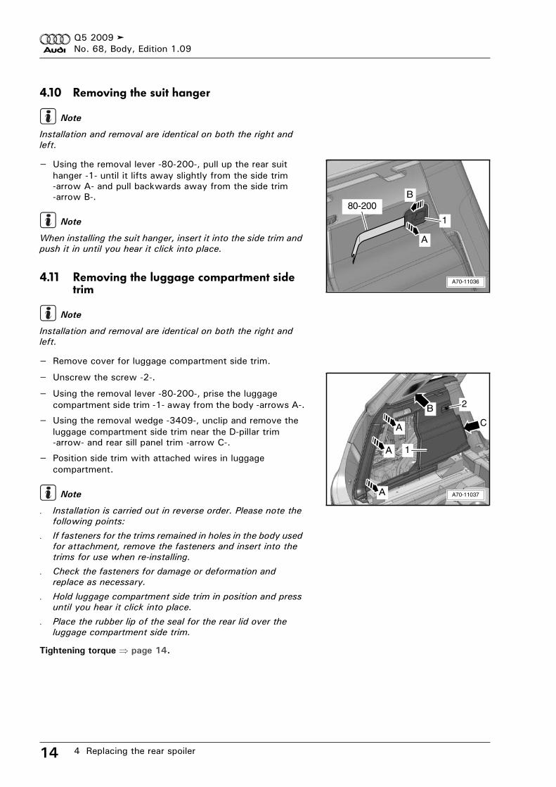
4.10 Removing the suit hanger
Installation and removal are identical on both the right and
left.
– Using the removal lever -80-200-, pull up the rear suit hanger -1- until it lifts away slightly from the side trim -arrow A- and pull backwards away from the side trim -arrow B-.
When installing the suit hanger, insert it into the side trim and
push it in until you hear it click into place.
4.11 Removing the luggage compartment side trim
Installation and removal are identical on both the right and
left.
– Remove cover for luggage compartment side trim.
– Unscrew the screw -2-.
– Using the removal lever -80-200-, prise the luggage compartment side trim -1- away from the body -arrows A-.
– Using the removal wedge -3409-, unclip and remove the luggage compartment side trim near the D-pillar trim -arrow- and rear sill panel trim -arrow C-.
– Position side trim with attached wires in luggage compartment.
. Installation is carried out in reverse order. Please note the
following points:
. If fasteners for the trims remained in holes in the body used
for attachment, remove the fasteners and insert into the
trims for use when re-installing.
. Check the fasteners for damage or deformation and
replace as necessary.
. Hold luggage compartment side trim in position and press
until you hear it click into place.
. Place the rubber lip of the seal for the rear lid over the
luggage compartment side trim.
Tightening torque page 14.
Note
A70-11036
80-200
A
B
1Note
Note
CA
A
B
A70-11037A
1
2
Note
Q5 2009No. 68, Body, Edition 1.09
4 Replacing the rear spoiler 15
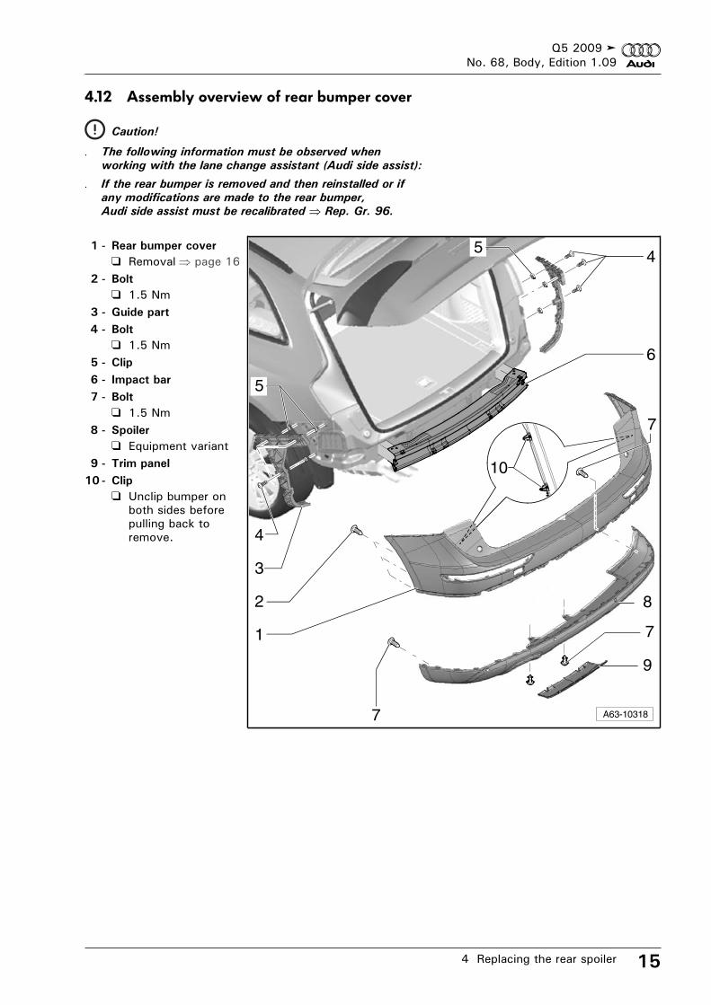
4.12 Assembly overview of rear bumper cover
1 - Rear bumper cover
Removal page 162 - Bolt
1.5 Nm3 - Guide part
4 - Bolt
1.5 Nm5 - Clip
6 - Impact bar
7 - Bolt
1.5 Nm8 - Spoiler
Equipment variant9 - Trim panel
10 - Clip
Unclip bumper on both sides before pulling back to remove.
Caution!
. The following information must be observed when
working with the lane change assistant (Audi side assist):
. If the rear bumper is removed and then reinstalled or if
any modifications are made to the rear bumper,
Audi side assist must be recalibrated Rep. Gr. 96.
A63-10318
2
5
7
3
4
5
8
9
7
4
6
1
10
7
Q5 2009No. 68, Body, Edition 1.09
4 Replacing the rear spoiler16
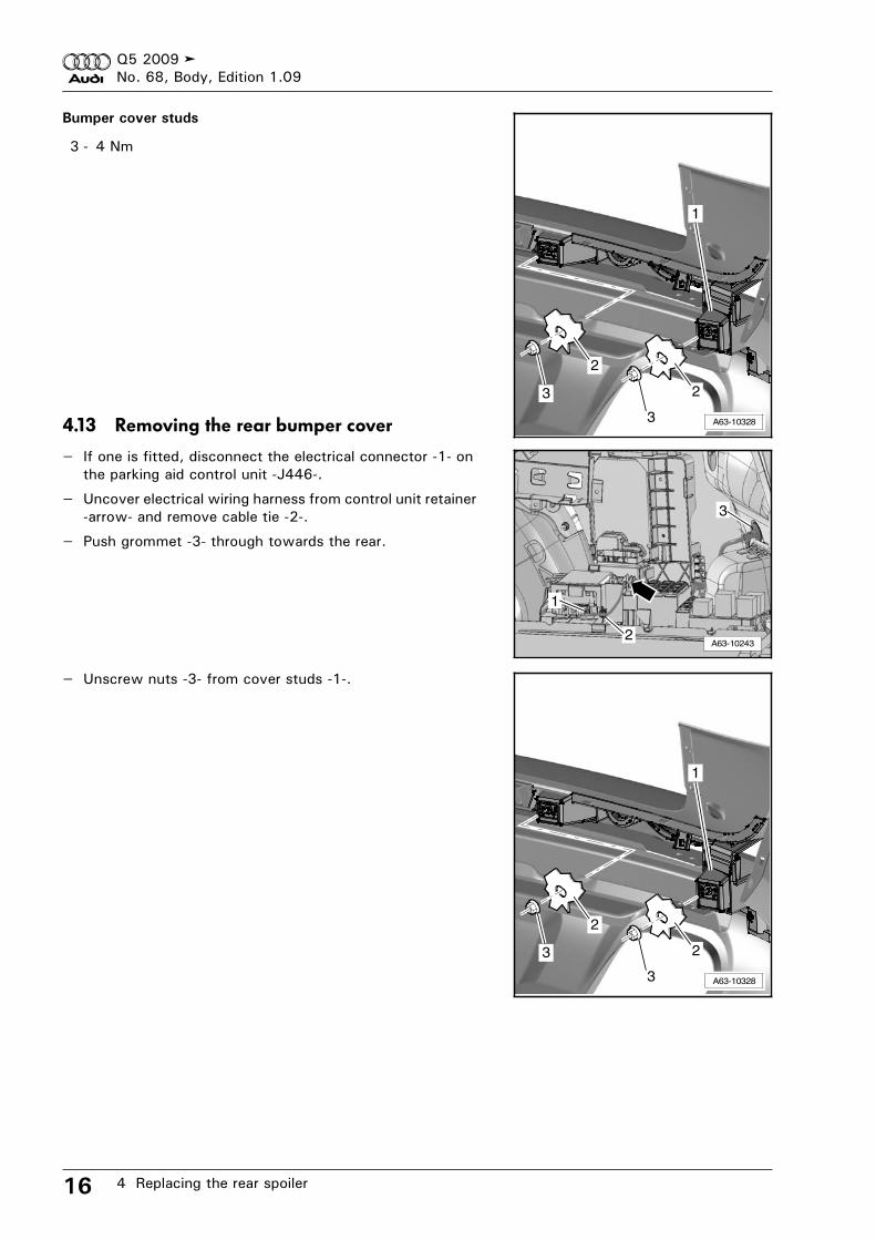
Bumper cover studs
3 - 4 Nm
4.13 Removing the rear bumper cover
– If one is fitted, disconnect the electrical connector -1- on the parking aid control unit -J446-.
– Uncover electrical wiring harness from control unit retainer -arrow- and remove cable tie -2-.
– Push grommet -3- through towards the rear.
– Unscrew nuts -3- from cover studs -1-.
A63-10328
1
2
3
2
3
A63-10243
1
2
3
A63-10328
1
2
3
2
3
Q5 2009No. 68, Body, Edition 1.09
4 Replacing the rear spoiler 17
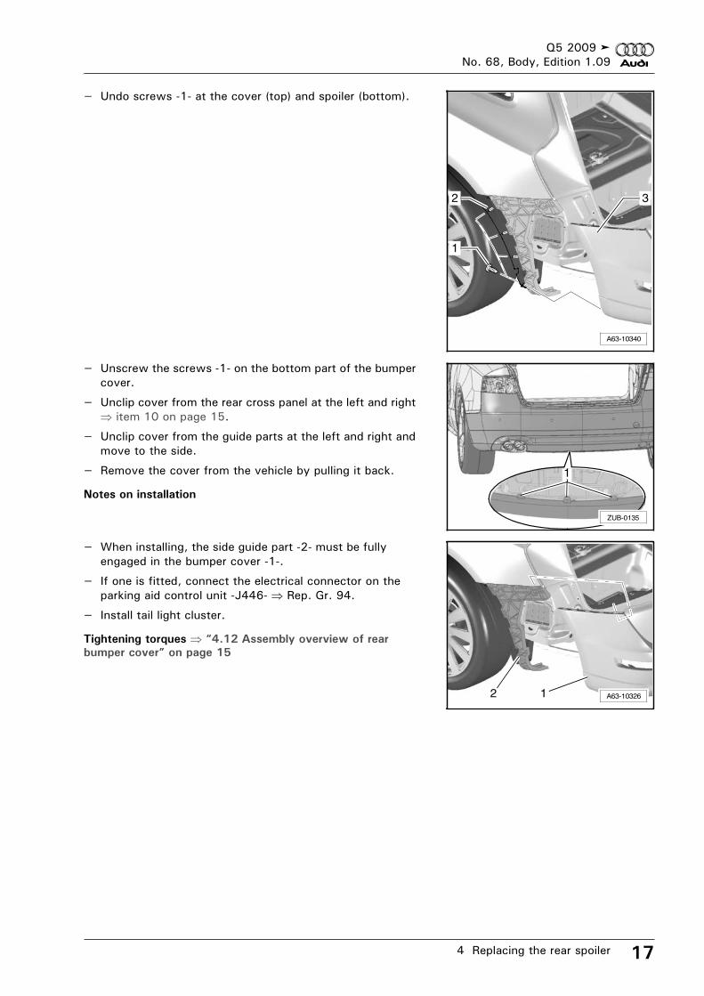
– Undo screws -1- at the cover (top) and spoiler (bottom).
– Unscrew the screws -1- on the bottom part of the bumper cover.
– Unclip cover from the rear cross panel at the left and right item 10 on page 15.
– Unclip cover from the guide parts at the left and right and move to the side.
– Remove the cover from the vehicle by pulling it back.
Notes on installation
– When installing, the side guide part -2- must be fully engaged in the bumper cover -1-.
– If one is fitted, connect the electrical connector on the parking aid control unit -J446- Rep. Gr. 94.
– Install tail light cluster.
Tightening torques “4.12 Assembly overview of rear
bumper cover” on page 15
A63-10340
1
2 3
1
ZUB-0135
A63-1032612
Q5 2009No. 68, Body, Edition 1.09
4 Replacing the rear spoiler18
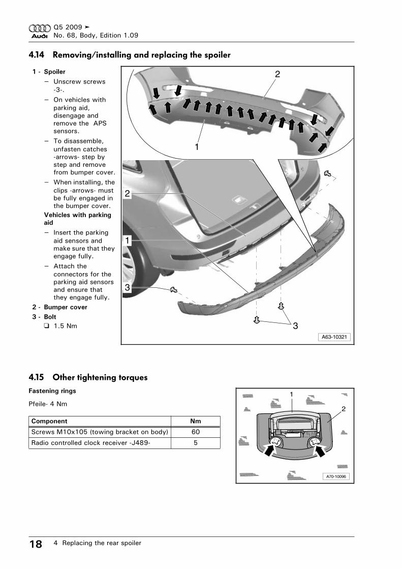
4.14 Removing/installing and replacing the spoiler
1 - Spoiler
– Unscrew screws -3-.
– On vehicles with parking aid, disengage and remove the APS sensors.
– To disassemble, unfasten catches -arrows- step by step and remove from bumper cover.
– When installing, the clips -arrows- must be fully engaged in the bumper cover.
Vehicles with parking
aid
– Insert the parking aid sensors and make sure that they engage fully.
– Attach the connectors for the parking aid sensors and ensure that they engage fully.
2 - Bumper cover
3 - Bolt
1.5 Nm
4.15 Other tightening torquesFastening rings
Pfeile - 4 Nm
1
A63-10321
2
1
2
3
3
Component Nm
Screws M10x105 (towing bracket on body) 60
Radio controlled clock receiver -J489- 5
A70-10096
1
2
Q5 2009No. 68, Body, Edition 1.09
5 Mounting trim covers for doors and wheel arch trims 19
5 Mounting trim covers for doors and wheel arch trims
To ensure superior adhesion of the bonded components, the
vehicle and parts must be dry and “heated through”.
Special tools and workshop equipment required
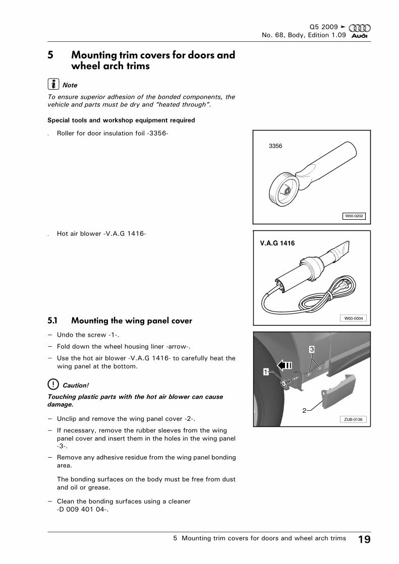
. Roller for door insulation foil -3356-
. Hot air blower -V.A.G 1416-
5.1 Mounting the wing panel cover
– Undo the screw -1-.
– Fold down the wheel housing liner -arrow-.
– Use the hot air blower -V.A.G 1416- to carefully heat the wing panel at the bottom.
– Unclip and remove the wing panel cover -2-.
– If necessary, remove the rubber sleeves from the wing panel cover and insert them in the holes in the wing panel -3-.
– Remove any adhesive residue from the wing panel bonding area.
The bonding surfaces on the body must be free from dust and oil or grease.
– Clean the bonding surfaces using a cleaner -D 009 401 04-.
Caution!
Touching plastic parts with the hot air blower can cause
damage.
Note
3356
W00-0202
3
ZUB-0136
1
2
Q5 2009No. 68, Body, Edition 1.09
5 Mounting trim covers for doors and wheel arch trims20
– Heat the bonding surfaces on the wing panel to approx. 40 °C using a hot air blower.
– Remove the protective film from the double-sided adhesive tape.
– Position the wing panel cover -2- and press it on. Listen for audible engagement (2 x).
– Once fitting is complete, press on the wing panel covers again using the roller for door insulation foil -3356-.
5.2 Fitting trim covers for doorsPrepare the trim covers for doors
– Clean the bonding surfaces of the trim covers for doors using a cleaner -D 009 401 04-.
– Use the hot air blower -V.A.G 1416- to carefully heat the trim covers for doors (max. 40 °C).
– Trim the side adhesive tape set -8R0 067 545 A- as required, stick to the bonding surfaces and press on firmly using the roller for door insulation foil -3356-.
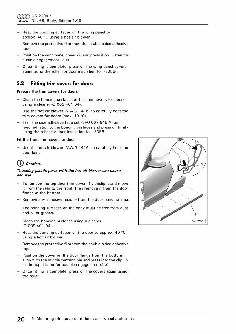
Fit the front trim cover for door
– Use the hot air blower -V.A.G 1416- to carefully heat the door leaf.
– To remove the top door trim cover -1-, unclip it and move it from the rear to the front; then remove it from the door flange at the bottom.
– Remove any adhesive residue from the door bonding area.
The bonding surfaces on the body must be free from dust and oil or grease.
– Clean the bonding surfaces using a cleaner -D 009 401 04-.
– Heat the bonding surfaces on the door to approx. 40 °Cusing a hot air blower.
– Remove the protective film from the double-sided adhesive tape.
– Position the cover on the door flange from the bottom, align with the middle centring pin and press into the clip -2- at the top. Listen for audible engagement (2 x).
– Once fitting is complete, press on the covers again using the roller.
Caution!
Touching plastic parts with the hot air blower can cause
damage.
A57-10498
1
1
2
Q5 2009No. 68, Body, Edition 1.09
5 Mounting trim covers for doors and wheel arch trims 21
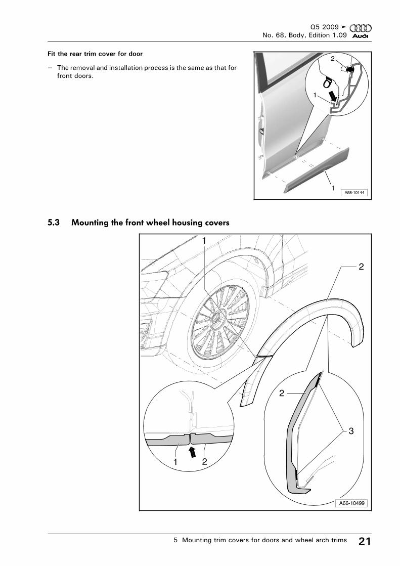
Fit the rear trim cover for door
– The removal and installation process is the same as that for front doors.
5.3 Mounting the front wheel housing covers
A58-101441
1
2
A66-10499
3
1
2
1 2
2
Q5 2009No. 68, Body, Edition 1.09
5 Mounting trim covers for doors and wheel arch trims22
The wing must be free from dust and grease in the adhesion area.
Install the bumper cover -1-
– Clean the bonding surfaces using a cleaner -D 009 401 04-.
– Heat the wing panel to approx. 40 °C in the bonding area using a hot air blower.
– Peel off the protective film from the lower adhesive tape.
– Peel off approx 5 cm of the protective film from each end of the upper adhesive tape and angle it upwards.
– Position the cover -1- at the spoiler by moving it to the front and to the stop and also ensure that it fits the contour of the wing panel exactly, then press it on gently.
– Peel off the protective film from the upper adhesive tape and press on the cover.
– Press on the cover evenly across the entire surface using the roller for door insulation foil -3356-.
Install the cover for the wing panel -2-
The bonding surfaces should have been cleaned using a cleaner -D 009 401 04-.
The wing panel should have been heated to approx. 40 °C in the bonding area using a hot air blower.
– Peel off the protective film from the lower adhesive tape.
– Peel off approx 5 cm of the protective film from each end of the upper adhesive tape and angle it upwards.
– Slide on the wing panel cover to the stop at the bumper cover -arrow- (invisible joint) and press it on gently.
– Peel off the protective film from the upper adhesive tape and press on the cover.
– Press on the cover evenly across the entire surface using the roller for door insulation foil -3356-.
Q5 2009No. 68, Body, Edition 1.09
5 Mounting trim covers for doors and wheel arch trims 23
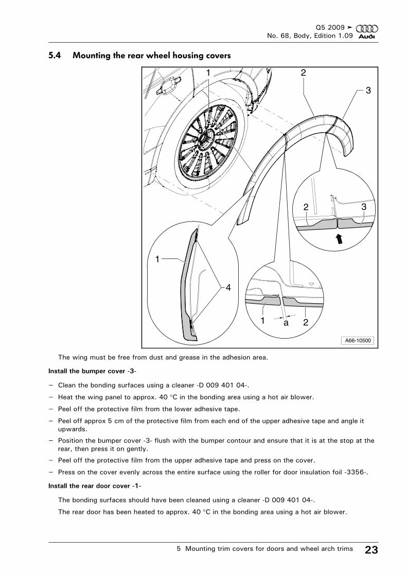
5.4 Mounting the rear wheel housing covers
The wing must be free from dust and grease in the adhesion area.
Install the bumper cover -3-
– Clean the bonding surfaces using a cleaner -D 009 401 04-.
– Heat the wing panel to approx. 40 °C in the bonding area using a hot air blower.
– Peel off the protective film from the lower adhesive tape.
– Peel off approx 5 cm of the protective film from each end of the upper adhesive tape and angle it upwards.
– Position the bumper cover -3- flush with the bumper contour and ensure that it is at the stop at the rear, then press it on gently.
– Peel off the protective film from the upper adhesive tape and press on the cover.
– Press on the cover evenly across the entire surface using the roller for door insulation foil -3356-.
Install the rear door cover -1-
The bonding surfaces should have been cleaned using a cleaner -D 009 401 04-.
The rear door has been heated to approx. 40 °C in the bonding area using a hot air blower.
3
A66-10500
3
4
a
1 2
2
21
1
Q5 2009No. 68, Body, Edition 1.09
5 Mounting trim covers for doors and wheel arch trims24
– Peel off the protective film from the lower adhesive tape.
– Peel off approx 5 cm of the protective film from each end of the upper adhesive tape and angle it upwards.
– Position the rear door cover -1- flush with the rear door contour and ensure that it is at the stop at the front, then press it on gently.
– Peel off the protective film from the upper adhesive tape and press on the cover.
– Press on the cover evenly across the entire surface using the roller for door insulation foil -3356-.
Install the wing panel cover -2-
The bonding surfaces should have been cleaned using a cleaner -D 009 401 04-.
The wing panel should have been heated to approx. 40 °C in the bonding area using a hot air blower.
– Peel off the protective film from the lower adhesive tape.
– Peel off approx 5 cm of the protective film from each end of the upper adhesive tape and angle it upwards.
– Position the cover -2- at the stop at the top, at the stop at the bumper cover and a set distance, -a-, from the rear door cover, then press it only gently.
Dimension -a- = 3.5 mm.
– Peel off the protective film from the upper adhesive tape and press on the cover.
– Press on the cover evenly across the entire surface using the roller for door insulation foil -3356-.
– Connect the vehicle battery earth wire Rep. Gr. 27.
– Observe the measures that apply after connecting the vehicle battery Rep. Gr. 27.
Q5 2009No. 68, Body, Edition 1.09
6 Appendices: Certificates, expert evaluations 25
6 Appendices: Certificates, expert evaluations
The following are included after the installation instructions:
. Parking aid sensors template - country variants (USA, Japan, China)
. the manufacturer's certificate of Audi AG
. Excerpt from the EC certification issued by the German Federal Motor Transport Authority
. the expert evaluation of the TÜV AUTOMOTIVE GMBH (Technischer Überwachungs Verein/Technical Inspection Authority)
Enclose any required country-specific documents from the
appendix with the vehicle documents, so that these can be
presented to authorised persons upon request.
Note