Embed Size (px)
Citation preview

4
NASA TECHNICAL
MEMORANDUMN__SA TM X-53453
July, 1966
tr_
f-
.,¢
/
THE FABRICATION OF BERYLLIUM ALLOYS- VOLUME
FORMING TECHNIQUES FOR BERYLLIUM ALLOYS
By R. F. Williams and S. E. Ingels
Manufacturing Research and Technology Division
Manufacturing Engineering Laboratory
I1:
N 67-19658IACCESSION NUMBER}|
: /(j/{PAGES)
5
_IASA CR OR TMX O_R AD NUMBER)
(THRU)
/(CODEI _
(CATB_ORY) _
NASA
George C. Marshall
Space Flight Center,
Huntsville, Alabama
https://ntrs.nasa.gov/search.jsp?R=19670010329 2018-06-04T06:28:25+00:00Z

TECHNICAL MEMORANDUM X-53453
THE FABRICATION OF BERYLLIUM ALLOYS-VOLUME II.
FORMING TECHNIQUES FOR BERYLLIUM ALLOYS
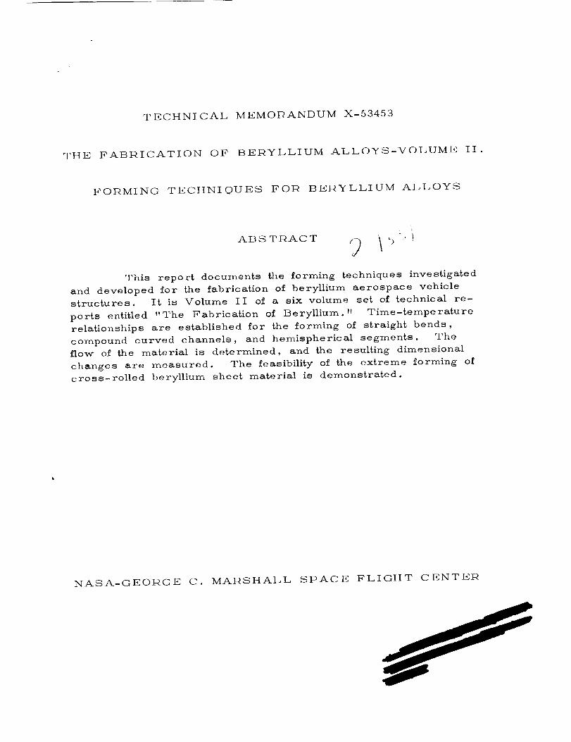
ABSTRACT
This report documents the forming 6echniques investigated
and developed for the fabrication of beryllium aerospace vehiclestructures. It is Volume II of a six volume set of technical re-
ports entitled "The Fabrication of Beryllium." Time-temperature
relationships are established for the forming of straight bends,
compound curved channels, and hemispherical segments. The
flow of the material is determined, and the resulting dimensional
changes are measured. The feasibility of the extreme forming of
cross-rolled beryllium sheet material is demonstrated.
NASA-GEORGE C. MARSHALL SPAOE FLIGHT CENTER


NA_A-GI*]OI2GE C. MAtqSHALL SPACE FLIGHT CENTER
TECI-INICAL MEMORANDUM X-53453
THE PABPICATION OF BERYLLIUM ALLOYS - VOLUME II.
FOt2MING TI_CHNIQUES FOR BERYLLIUM ALLOYS
By 1_. F. Williams and S. E. Ingels
The other Volumes of Technical Memorandum X-53453 are:
I
Vol. I. A Survey of Current Technology
Vol. III. Metal lqernoval Techniques for Beryllium Alloys
Vol. IV. Surface Treatments for Beryllium Alloys
Vol. V. Thermal Treatments for Beryllium Alloys
Vol. VI. Joining Techniques for Beryllium Alloys
MANUFACTURING I_NGINI_ERING LABORATORY
ACK NOWL ED G EMENT
The _vork accomplished to generate the information
enclosed in this report was perforrmed under Contract Ix_AS8 -
II798 by Large Space Vehicle Programs, Space Systems
Division, Lockheed Missiles and Space Company. The program
encompasses {;he development and documentation of needed new
rmanufacturing techniques and fabrication methods suitable for the
application of beryllium and berylliuno alloys in space flight vehicle
structures.
Mr. ]q. F. Williams, NASA Advanced Manufacturing
Programs, was the Project Manager of this effort under the
rr_anagerment of Mr. J. T'.. Hart, Manager, NASA Advanced
Development Programs, Lockheed Missiles and Space Company.
The work was performed under the technical direction of Mr.
S. E. Ingels assisted by Mr. C. Fruth in preparation of the
final report.

TABLE OF CONTENTS
Page
S ECTION I .
SECTION II.
SECTION llI.
SECTION IV.
INTRODUCTION ......... 1
GENERAL ............. 2
FOB
A.
C ,
MINO PROCESSES ...... 5
Straight Bends ......... 5
1. Minimum Radius Bend
I nves%igation ..... , .... 5
2. Channels .......... 26
3. Zee Sections ........ 31
4. Hat Sections ........ 31
5. Metallographic Analyses • 38
6. Roll Forming ........ 47
Compound Curves ........ 53
1. Spherical Segment ...... 53
2. Channel Ring Segment .... 62
3. Deep Drawing ........ 69
Joggling ............ 71
CONCLUSIONS AND
R ECOMMENDATI ONS • 76
fir

LIST OF ILLUSTI_ATIONS
,
,
,
,
•
,
•
,
Title
Universal Forming Die
Note the Heating Elements and Stainless Steel
Buffer Plates . . . ............
Minimum l_adius (4t) Bend - 0.020-Inch
Material- 1350°F Category i Quality-
No Defects ...............
Cross-Section; Minimum Radius (4t) Bend-
0.020-Inch Material - 1350°F Category I
Quality- No Defects - 500X ........
Minimum _Radius (4t) Bend - 0.060-Inch
Material- 1350°F Category 2 Quality-
Questionable; Strain Lines Visible, but No
Open Cleavage ..............
Cross-Section; Minimum Radius (4t) Bend-
0.060-1nch Material - 1350°F Category 2
Quality- 500X ..............
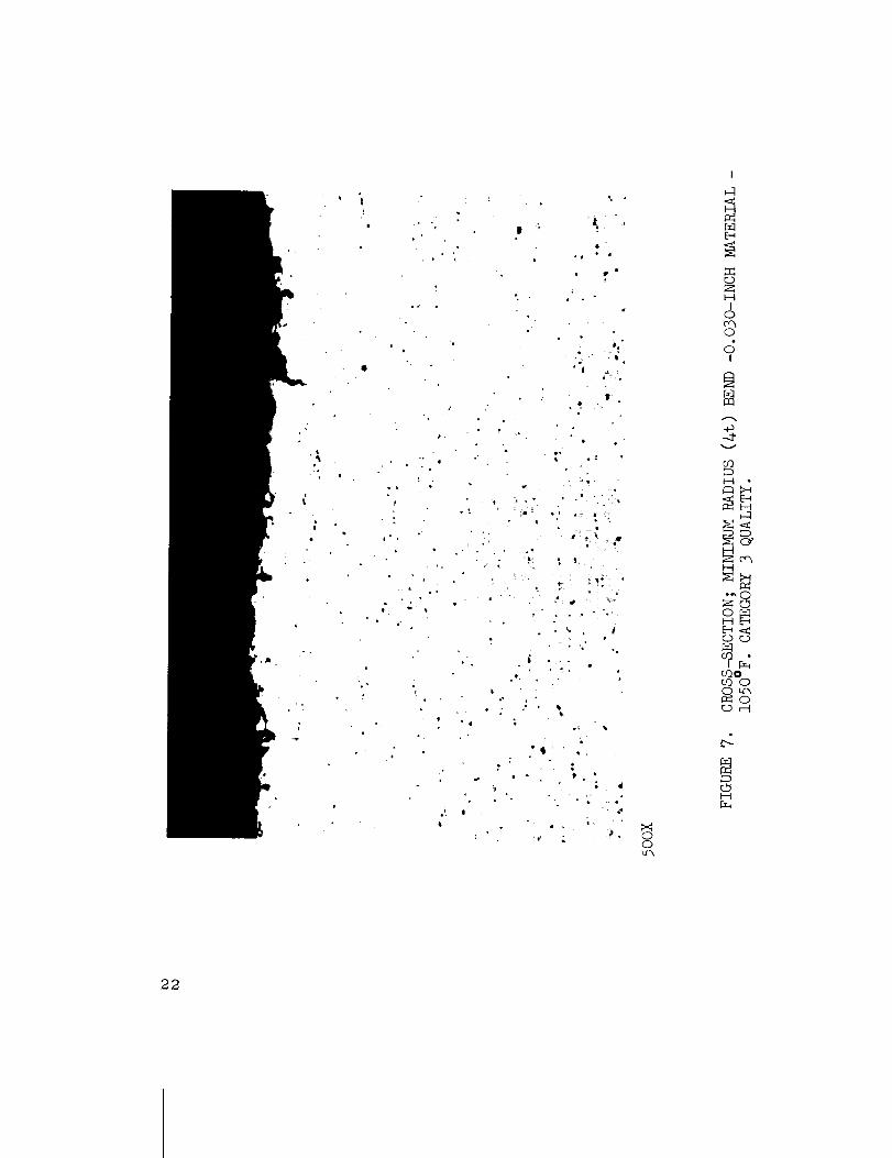
Minimum Radius (4t) Bend - 0. 030-Inch
Material- 1050°F Category 3 Quality-
Incipient Failure, Minor Cleavage ......
Cross-Section; Minimum Radius (4t) Bend-
0.030-Inch Material - 1050°F Category 3
Quality- 500X .............
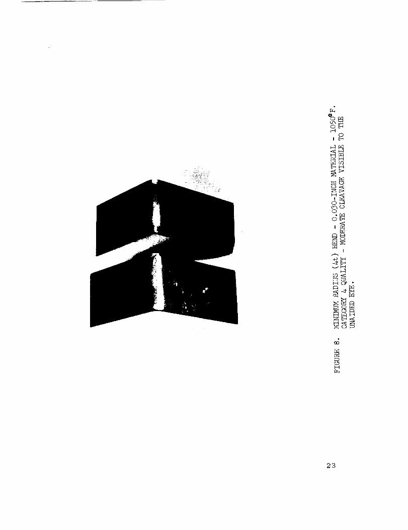
Minimum lqadius (4t) Bend - 0.030-Inch
Material- 1050°F Category 4 Quality-
Moderate Cleavage Visible to the Unaided
Eye ...................
Cross-Section; Minimum iRadius (4t) Bend-
0.030-Inch Material - 1050°F Category 4
Quality- 500X ..............
P age
17
18
19
2O
21
22
23
24
iv

LIST OF ILLUSTRATIONS (Cont'd)
Figure
I0.
II.
12.
13.
14.
15.
16.
17.
18.
19.
Title P age
Minimum 12adius (4t) Bend - 0.120-Inch
Material - 1050°F Category 5 Ouality -
Gross Failure, Visible Fractures ........ 25
Cross-Section; Minimum !_adius (4t) Bend-
0.120-1nch Material - 1050°F Category 5
(Duality- 100X ................. 27
Assembled Leaf Brake Die. Note the
S_eel Frame and £he "Glassrock" Die
Blocks ..................... 29
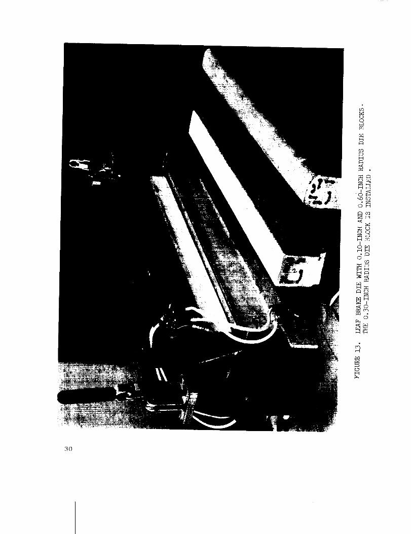
I.eaf Brake Die with 0.10-Inch and 0.060-
Inch I_adius Die Blocks. The 0.30-Inch
]_adius Die Block is Installed .......... 30
I,As Formed" Specimens. Warped Due to
Uneven Temperature .............. 32
I_epresentative Channel Sections Formed on
the Leaf Brake Stress l_elieved and
Straightened ............. 33
Channel Being Formed on the Press Brake•
Note the Steel Plates on Both Sides of the
Beryllium Specimen .............. 34
Channel Formed on the Press BraiSe at 100°F
Note the Catastrophic Failure ....... 35
Zee Section Being Stress lqelieved in the
Universal Forming Die. Note the Stainless
Steel Buffer Plates and the I i/2-Degree
Springback _Adlowance on the Left Side of
The Punch i_lock ............ • 36
Pepresentative Zee Sections Formed on the
Leaf Brake, S£ress ]_elieved and S£raightened. . 37
/
V

LIST OF ILLUSTI_ATIONS (Conttd)
F igu re
20.
21.
22.
23.
24.
25.
26.
27.
28.
Title P age
Hat Section Formed in the Universal
Forming Die Without Buffer Strips or
Lubricant. Note the Severe Oalling ...... 39
Representative Hat Sections Formed on
the Universal Forming Die ........... 40
I_epresentative Cross-Section of "Punch
and Die" Formed }-/at Section - 0.060-
Inch Material ................. 41
Typical Delarnination in Bend Area of
l'P_nch and Die" Formed Hat Section -
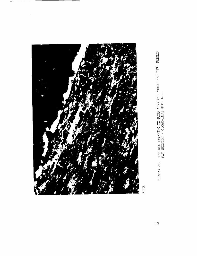
0.060-Inch Material - 500X .......... 42
Typical Twinning in Bend Area of
"Punch and Die" Formed Hat Section -
0.060-1nch Material - 500X ........... 43
lqepresentative Cross-Section of Channel
Formed on the Leaf Brake - 0.060-
Inch Material .................. 44
Typical Delamination in Bend Area of
Channel Formed on the Leaf Brake -
0.060-Inch Material - 500X. l_outine
0.002-1rich Etching Subsequent to Form-
ing Will Remove This Defect ........... 45
Typical Twinning in Bend Area of Channel
Formed on the Leaf Brake - 0.060-Inch
Materail- 500X. Very Little Twinning
Occurred ................... 46
]_epresentative Cross-Section of Zee
Section Formed on the Leaf Brake -
0. 120-1nch Material .............. 48
v±

LIST OF ILLUSTRATIONS (Conted}
Figure
29.
30.
31.
32.
33.
34.
35.
36.
Title
Typical Cross-Section of the Bend Area
of the Zee Section Formed on the Leaf
Brake - 0.120-Inch Material - 500X.
Note Absence of Subsurface Delamination
Typical Cross-Section of the Bend Area
of the Zee Section Formed on the Leaf
Brake - 0.120-Inch Material- 500X.
Note Absence of Twinning ..........
Experimental "Punch arid Die" - Pre-
liminary Spherical Radius Forming - 3.0-
Inch l_adius ............
Experimental Hemispherical Segments -
Preliminary Forming. Note Wrinl_lingof the 0.020-Inch and 0.030-Inch
S egrr_ents ..................
Experimental Hemispherical Segment-
0.020-Inch Material. Note the Severe
Folding of the Material ............
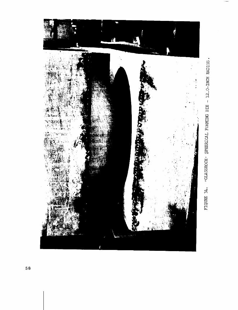
"Glassrock" Spherical Forming Die -i2.0-Inch Radius ..............
Spherical Segments - 0.020-Inch Beryl-
lium and 0.060-Inch 61SO Aluminum Formed
at 1350°F and !_oom Temperature l_espective-
1y. Note the Similarity of the Wrinkles at
the edges of the Specimens .........
Specimen Blank and Formed Spherical
Segment - 0.120-Inch Material - 12.0-
Inch Radius - 100 !_/t ...........
P age
49
50
54
55
56
58
59
6O
vii

LIST OF ILLUSTRATIONS (Contld)
F igu re
37.
38.
39.
40.
4i.
42.
43.
44.
45.
T itl e
Scribed Inner Surfece of the Formed
Spherical Segment- 1.00-Inch Orid -
0.120-Inch Material - 12.0-Inch 19adius-
i00 lq/t ...................
Curved Channel Configuration - Nominal
Dimensions ..................
"Olassrock" Curved Channel Forming
Die Blocks ..................
Curved Channel Being Formed - 0.120-
Inch Material .................
Specimen Blank and !_epresentative Curved
Channel ...................
Curved Channel Specimen - 1.00-1nch Grid -
0.120-1nch Material. Note the Displacement
of the Grid Lines end _he Variation in Flange
Height ....................
Beryllium Angles in Place in Joggle Die.
Supplementary Heating Provided by Quartz
Lamps. ]kTote the Scale on the Die Blocks . . .
Typical Joggled Angles with "Pinched" Angle
Bend Radius ...............
tqepresentative Satisfactory Joggled Angles.Note the Smooth Transition and Lack of Bend
P adius "Pinching" ..............
P age
61
65
66
67
68
7O
73
77
78
viii

LIST OF TABLES
II.
III.
IV.
V •
VI.
VII .
VIII.
TRIe P age
Chemical Analyses and Mechanical Properties-
Material for Forming Specimens ........
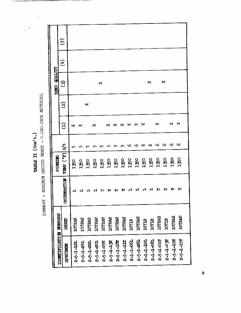
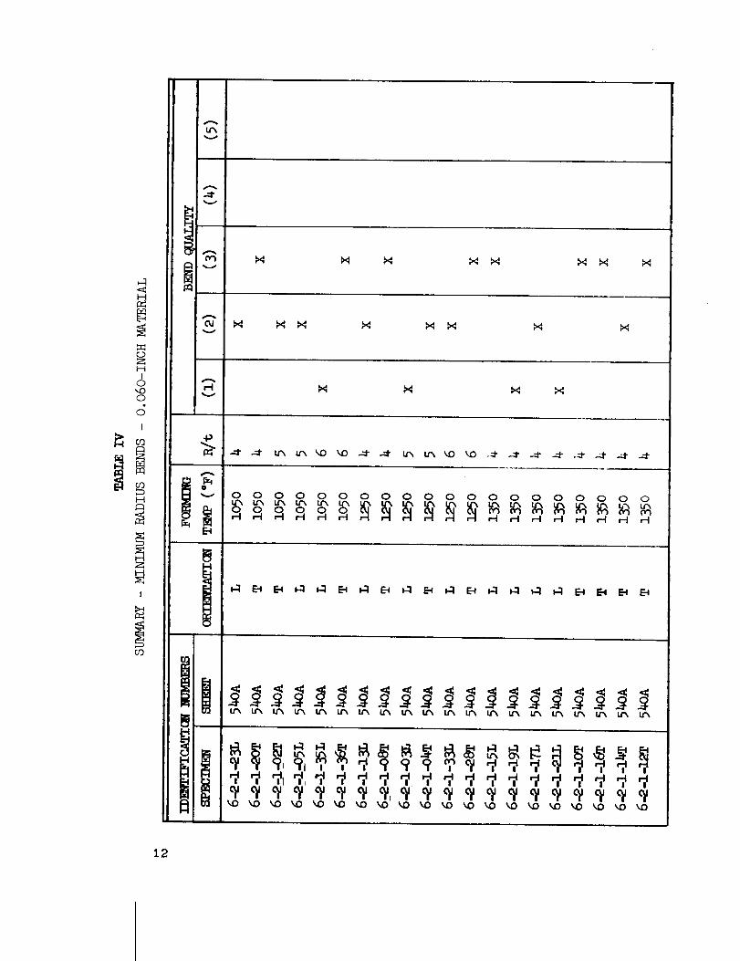
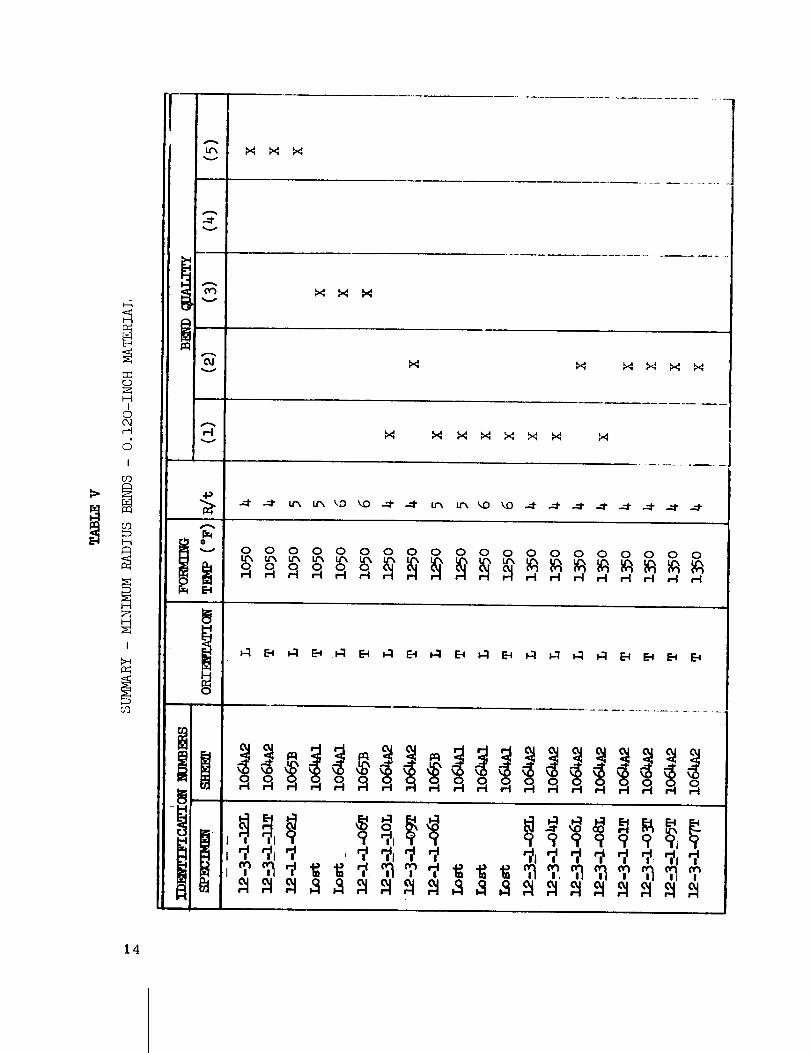
Summary - Minimum l_adius Bends - 0.020-
Inch Material ................. 8
Summary - Minimum Radius Bends - 0.030-
Inch Material ................. 10
Summary - Minimum l_adius Bends - 0.060-
Inch Material ................. 12
Summary - Minimum l_adius Bends - 0.120-
Inch Material ................. 14
Hardness Survey of Curved Specimens ..... 52
Summary- Spherical Segments ........ 63
Summary - Joggled Angles .......... 74
ix


TECHNICAL MEMORANDUM X-53453
THE FABRICATION OF BERYLI, IUM ALLOYS - VOLUME II.
FORMING TECHNIQUES FOR BERYLLIUM ALLOYS
SECTION I. INTRODUCTION
The objectives of' this task are the investigation, develop-
ment, and documentation of the beryllium fabrication methods class-
ified as "Forming I' in the Beryllium Fabrication Methods lDavelop-
ment Program Plan.
The availibility of cross-rolled beryllium sheet material
of uniform quality, in sizes compatible with design requirements,
now makes possible .the full realization of the potential advantages
of beryllium in the fabrication of aerospace vehicle structures.
Although large radius, simple curved panels are being formed on
a routine production basis, the lack of suitable production tech-
niques for the forming of minimum bends and compound curves
s_ill inhibits the extensive utilization of beryllium in the fabrication
of large space vehicle structures.
The several tasks accomplished during this study included
the experimental forming of both simple and compound configura-tions as follows:
1. Straight Bends
Angles
Channels
Zee Sections
Hat Sections

2. Compound curved configurations
Spherical Segments
Channel I_ing Segments
3. Joggles
Angles
The accorr_plishment of these tasks, directed toward thedevelopment of both engineering and production information anddata_ included the documentation of tile opti_nun_ forming tempera-ture_ the establishment of minimum bend radii, and the verificationof the feasibility of forming abrupt dimensional changes in theplane of the material.
SECTION II. GENERAL
The material utilized in the accomplishment of the tasksincluded in this phase of the program was commercial qualitycross-rolled beryllium sheet purchased from the Brush Beryl-lium Company of Cleveland, Ohio. This material was purchasedin accordance with the specification requirexments and containedthe following minimum specific properties:
a. Ptu - 70,000 psi
b. Fry - 50,000 psi
c. /n;lo ngatio n 5% in 1.0 inch
Table I presents [he chemical analyses and the mechani-cal properties of the material.
With the exception of the joggle dies, all of the tooling
used during this program was fabricated of "Glassroek," aceramic material with very stable thermal characteristics.
Either 11 or 14-gage nichrome wire heating elen-_ents, spaced1/2-inch apart, were imbedded in the rnat, erial 1/2-inch from f,he

_.D r--I r--I r-H
c:; c; c; d
r._
IiI
,g;.lr..i
I!
Hr_
ft
I
1
...qo
H
O
d
._qo
,---t
..0©
d,..Co
O0"h_oo
I--I
o
£_,s.O
O
,--I ,-_ o-, '0B
r'-I c'_ O OO O O O
c; cld d
0", _ 0 r--I0 O 0 r-I
ddd cl
•_ _ -d- c,_, -_-I _ 0 C) 0 O
dddda3
!I d d Sd
c_?
o _,_ _ocO t"-
ro
O
d
4r.O
O
O
3

c_
-_ ¢_
O
V
!
.l-I
cc_ Ld_
!
a_
!
4

the working surface.
Although the low fabrication cost of this "tooling" mate-
rial makes its use particularly attractive for limited "runs", the
applications must be selected with care to avoid overstressing
of the "Glassrock." Analyses of the several tooling failures,
experienced during the accomplishment of this program, are in-
cluded in the discussion of the pertinent forming task.
SECTION III. FOIqMING PlqOCESSES
A. STRAIGHT BENDS
The roost basic forming operation, required during
the fabrication of structural components, is the straight bend.
The object of this first phase of the program was the determina-
tion of the time-temperature parameters required for the consistent
and reliable production of minimum radius bends.
1. Minir_uro Radius Bend Investigation. This
initial phase of the program included not only the establishment
of the basic forming parameters, but the determination of the
minirpum radius bends that could be consistently produced. In
order to obtain representative comparative data, a set of thirty-
six 90-degree angle specimens was formed of each of the four
material gages. All of the specimens were formed of each of
the four material gages. All of the specimens were formed at
the desired radii of 4, 5, and 6t, and the selected forming
temperatures of 1050°F, 1250°F, and 1350°F. The forming
temperatures were recorded by means of chromel-alumel thermo-
coup]es_ installed on control specimens, and a Honeywell 20
channel strip recorder. A "feedback loop" to the electric power
supply provided the necessary control of the forming temperatures.
Current production procedures were utilized
for the preparation of the basic 1.0 by 3.5 inch uniform test
specimens. All of the specimens were identified during the
initial layout on full size vellum sheets, and this identification was
maintained throughout the program. The layout, including the
identifying numbers, was transferred to the sheet material, and
the parts were cut to size on the precision abrasive cut-off saw.
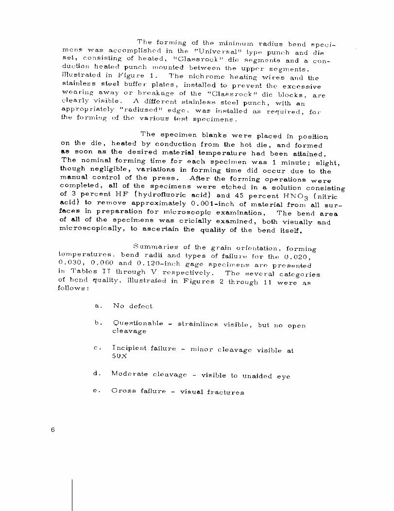
The forming of the minimum radius bend speci-
mens was accomplished in the "Universal" type punch and die
set, consisting of heated, "Glassrock" die segments and a con-
duction heated punch mounted between the upper segments,
illustrated in Figure 1. The nichrome heating wires and the
stainless steel buffer plates, installed to prevent the excessive
wearing away or breakage of the "Olassrock" die blocks, are
clearly visible. A different stainless steel punch, with an
appropriately "radiused" edge, was installed as required, for
_he forming of the various test specimens.
The specimen blanks were placed in position
on the die, heated by conduction from the hot die, and formed
as soon as the desired material temperature had been attained.
The nominal forming time for each specimen was 1 minute; slight,
though negligible, variations in forming time did occur due to the
manual control of the press. After the forming operations were
completed, all of the specimens were etched in a solution consisting
of 3 percent HE (hydrofluoric acid) and 45 percent HNO 3 (nitric
acid) to remove approximately 0.001-inch of material from all sur-
faces in preparation for microscopic examination. The bend area
of all of the specimens was cricially examined, both visually and
microscopically, to ascer%ain the quality of the bend itself.
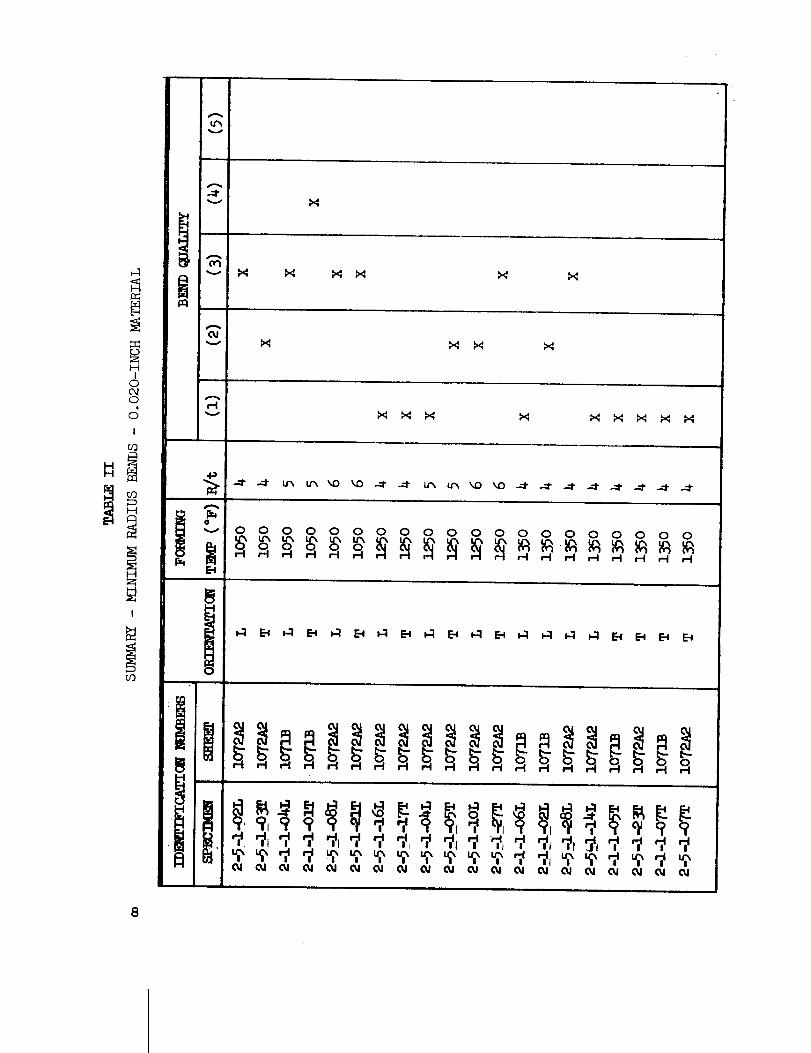
Summaries of the grain orientation, forming
temperatures, bend radii and types of failure for the 0.020,
0.030, 0.060 and 0.120-inch gage specimens are presented
in Tables II through V respectively. The several categories
of bend quality, illustrated in Figures 2 through 11 were asfollows :
a. No defect
b • Ouestionable - strainlines visible, but no open
cl e avage
C J Incipient failure - minor cleavage visible at50X
d. Moderate cleavage - visible to unaided eye
e. Oross failure - visual fractures

|
O*_6Wp.,I_ m
!
/
&
c_
H
cs_
_H°_
sm_
I-tI
13
V
V
I

v
v
v
o
HI
0
0
v
J
H
O
0 0 0 0 0 0 0 0 0 0 0 0 0 0 0 0 0 0 0 0
H
H
I
I-4
10

v
(D
I--HI
00%0
J" I
v
I
c_
A
0q
A
OJ
r-I I_ X I_ I_ _ 1,4 I_ I_ _I X I_ _ _ _ I_
0 0 0 0 0 0 0 0 0 0 0 0 0 0 0 0
11
v
_q
0_o0
c_I
I
i-I
i
oooo ooooooo ooooooo_O _D _3 _3
12

H
C_ .....
13
u_ I_ 1,4 X
v_4 _ 1,4
r..)ZH
I
o
dI
,-I _4 _I 1,4 _4 N1 1,4 _I M
4_
r_
0 0 0 0 0 0 0 0 0 0 0 0 0 0 0 0 0 0 0 0
I
14

r_3
I-4I
C3
r-4
"-"+;
o
I
09
v
Ol
,-Iv
u_ u'_ u'_ u-_ u'_ uTM, _ u_ _D kid kO _O kO _ kO _0
0 0 0 0 0 0 0 0 0 0 0 0 0 0 0 0
_ _ _ _ _ _ E4 _ t-1 _ _ E-I _ E-I
15

The material gages, the bend radii, and the
forming temperatures are presented with the illustrations of the
several categories of defects.
Visual examination of a category 1 specimen,
illustrated in Figure 2, revealed little or no appreciable change
in surface texture of the specimen. Critical microscopic examina-
tion of a cross-section of the same specimen at 500X, i]lustrated
in Figure 3, revealed only the typical surface condition of slight
undulations; there were no sharp notches or other indications of
potential failure .
Visual examination of a category 2 specimen
illustrated in Figure 4, revealed fine lines or a very slight
orange peel appearance of the outer fibers of the specimen.
The microscopic examination of the cross section at 500X,
illustrated in Figure 5, verified the presence of the fine lines as
a series of slight, but sharply defined, indentations.
The surface conditions of the category 3 speci-
men, illustrated in Figure 6, are very similar to that of the cate-
gory 2 specimen, except that the lines are more pronounced and
clearly visible. The microscopic examination of the specimen at
500X. illustrated in Figure 7, verified the presence of moderate
surface cleavage. The slight separation of particles of beryl-
lium from the basic material may be noted in the illustrations.
Although an additional etching operation to remove approximately
0.002-inch of material from the surface would result in the
removal of these defects, the overall condition is considered to
be marginal.
The fracture in the bend area of the category
4 specimen is clearly visible in Figure 8. The 500X magnified
cross-section of the specimen, illustrated in Figure 9, clearly
shows the magnitude of the fracture. The sharply defined in-
dentations adiacent to the fracture clearly indicate the progressive
strain condition existing in the surface of the beryllium.
No magnification was required for the examina-
tion and evaluation of the category 5 type of specimen defect.
The cleavage of the beryllium in the bend area, clearly illustrated
in Figure 10, may be easily observed with the unaided eye.
The microscopic cross-section of the specimen at 100X (not
16

00
I
HI0 °O_cOOE_.0
Z
I
g_
_g
I-4
17

°'.
r
!
TIi
_. °
q'_II
!
Q •
ii
o
• I
J
w
q_
0
Z_
0
Q_
0o
I-I
Io LI_
cr_
i-i
18

%u-,,mo_r._i.--IH
I
H
ZH "4'
O,_q
OOH
HO _A _
_o
_ o8_
19
-.4
H

q
.e
t
°e
a 'Q ,
!
°"
t*
e..
_ °
e
#
q,#
• .°
,d
"'r
#
i
,r • ,
*m
o4
q • •
i
.- _ -.
• .°..
• °
i"
.o
?.
I
°
°
• .
|
w
b°
Do
oe
t
J
g . -
°.
D
! •
o.II ! .._
. °
o
'9" • •
o
00
I
zt-(
I0,,,o0
dI
v
oo
,-.1
£8I..-I
r__,-.4
2O

Ic_
HHIo_
c_OEl_
._
°_H
I
vH
I--Ir_
21
8'
• °r
i
.°J_
i
j'
0i °
i'|
|• IP •
Q
_,°
1
e
• . i L t
, 4
o
- ° •° °
tq
O
I
HI
Oc_O
I
v
O
coo
0
_z
H
22
0
0I E-_
Z_
IOc,'h c_O
I
HO' °A
28
H

¢
I
I
I©
©
I
V
A
O
c_
o
H
24

0
E_
H
I--I •I
0
r_H
I
,_ I--t
r-t
oH
25

500_ as heretofore), illustrated in Figure 11, clearly reveals
the sharp cleavage of the beryllium, the potential progressive
failure on the bottom of the crack, and other potential failures
adiacent to the main fracture.
The analysis of the information and data present-
ed in the tables and figures indicated that St radius bends could
be consistently and reliably produced in all gages of material at
a ferrying temperature of 1350°F. The results of the tests con-
ducted at 1250°F were very inconsistent, and those at 1050°F
were so inconsistent as to be considered unsatisfactory. In
addition, only the 0.020 and 0.030-inch gage specirpens could
be reliably formed at the 4t radius at the 1350°F forming tempera-
tu re .
Therefore, a minimum radius of 5t and a form-
ing tennperature of 1350°F were utilized during all of the sub-
sequent forming operations.
2. Channels. In order to evaluate the effect of
the bend radius during actual forming operation, several different
procedures were ,_sed for the shaping of the channel test speci-
mens. The methods utilized for this investigation included a
conventional punch and die, a "Leaf" brake, and a standard
press brake. Due to the basic differences in the respective
procedures_ the results and pertinent discussions are presented
individually.
a. Conventional Punch and Die Method. The
successful forming of beryllium requires the close control of the
pertinent forming parameters, including: close dimensional con-
trol_ even temperature distribution within the die segments, and
even stress distribution. The conventional punch and die appear-
ed to meet all of these requirements.
The "Universal" Forming Die, modified
by the substitution of a heated "Olassrock" punch for the stain-
less steel punch, was used for this evaluation.
Although channel sections were success-
fully formed, the typically galled condition of the surface, illustrat-
ed in Figure 20j was very unacceptable. Beryllium is inherently
extremely abrasive, particularly at elevated temperatures, and
26

Lo
O
I
l-q
ZH
IO
!
G_
O_HE-<E_
(:2)rDr-t
OH
2'7

therefore very resistant to flow across other surfaces. During
this phase of the program, various lubricants were tried, but
as to yet no satisfactory material has been found which will main-
tain its lubricating properties at the required forming temperature,
and siroultaneously will not "build up" on the tool itself.
An alternate method is the use of "buffer"
sheets of stainless steel or molybdenum foil. The use of such
sheets does result in the forming of satisfactory channels, but
at greatly increased cost as the foil is expendable, and consider-
able additional tir_e is required for its placement in the die.
The discussion of the results is presented
in Section III, paragraph A5, Ik4etallographic Analyses.
b. Leaf Brake 19,e. This die, which
utilizes the "folding" principle, was designed and fabricated
to permit the evaluation of this forming method. In addition,
this method eliminates all need for lubricant and thus would
eliminate the galling problem.
The "Leaf" die, illustrated in Figure 12,
consisted of the basic frame, the center heated "Glassrock"
hold-down block and two heated t'Glassrock" leaves -- one on
either side. As illustrated in Figure 13, several hold-down
blocks_ incorporating different radius edges, were provided to
permit the forming of several configurations.
Prior to the actual forming, the specirne_
blanks were preheated to 1350-1400°F in a furnace. The blanks
then were transferred into the die and the consecutive "folding"
of the two sides of the channel was manually accomplished in
approximately 30 seconds per side.
Although the principle of the die was sound
and the galling problem was solved, various mechanical problems
occurred with this experimental tool during the program. These
problems, which would be eliminated in the design of a production
tool_ included insufficient clearance at the ends of the "Glassrock"
die blocks for the heating wires, inadequate support of the long
slender die blocks along their length and uneven heal distribution
due to the open nature of the die. The lack of even temperature
28

C.D(D
P3
_TqH
Ej
C)c_cQ_J3
o
½
z
CO
P_
29
3O
o_q_q
H
I-'4
t---I _
"-0 r_
OH
0
I
d _co
r-_

along the die blocks resulted in severe warpage of the specimens,
particularly with the thinner gages of material as illustrated in
Figure i4. Subsequent resizing and stress relieving of the
specimens in the Universal Forming Die at a temperature of 1350°F
for approximately 20 minutes resulted in the production of smooth
straight channel sections as illustrated in Figure 15.
c. Standard Press Brake. a standard 60-
ton Pacific hydraulic brake,equipped with heated platens, was used
for the forming of the 0. 120-inch channel specimens. Due to the
limited capacity of the power supply and the heating elements
( 1000°F maximum temperature), supplementary heat was supplied
by quartz lamps in order to attain the required forming tempera-
ture of 1350°F. The 0.120-inch beryllium blank was "sandwiched"
between 0.060-inch mild steel plates during the forming operation
to avoid galling the surface of the beryllium. This forming opera-
tion, illustrated in Figure 16, was unsuccessful. The thermal
characteristics of the beryllium and the large mass of the press
brake acting as a heat sink, precluded the maintenance of the
required temperature in the beryllium blank. This forming activ-
ity was discontinued after two attempts, made at a material tempera-
ture of approximately ll00°F, resulted in the catastrophic type of
failure illustrated in Figure 17.
3. Zee Sections. No unanticipated problems were
encountered during the forming of the Zee Sections on the Leaf
brake die. All forming was, of necessity, accomplished in two
steps, i.e., the blank was heated to 1350°F, placed in the die,
and the first leg of the Zee was formed. The specimen then
was reheated, placed in the die "upside down" from the previous
position and the final leg of the Zee was formed. As occurred
during the forming of the channel sections, the uneven tempera-
ture along the die resulted in the formation of warped specimens.
}/owever, a subsequent straightening and stress relieving opera-
tion, conducted in the Universal Forming Die at 1350°F for
approximately 20 minutes, corrected this condition. This opera-
tion is illustrated in Figure 18. Representative stress relieved
and straightened Zee sections are illustrated in Figure 19.
4. Hat Sections. As four separate operations
would have been required for the forming of the hat sections in
the leaf die, the "Olassrock" die segments were installed in the
Universal Forming Die, as illustrated in Figure 18, which
31

E_
32

1
o
o
_R
,-t
0b-t
33

Z
C._
I-I
,E-4
0
cO_q
m
oco
,-I
H
34

\
o
,-I
E-_
o2E-t
_o
r-i
35

_°
0p-q
36

,,,,,¢,-
t
.°."
o
Z r...bOH
b_
CO
H
3'7

permitted the forming of the hat sections in one operation. Thei I/2-degree springback clearance, visible on the left side ofthe punch, provided an undesirable unsupported area along this
face of the block. This allowance is not required for normal
formin_ operations at 1350°F.
The initial forming operations, conducted with-
out buffer strips resulted in the severe galling of the surface of
the material as illustrated in Figure 20. The subsequent in-
stallation of stainless steel buffer strips, visible in Figure 18,
alleviated this condition. Representative hat sections are illustrat-
ed in Figure 21.
5. Metallographic Analyses. In order to permit
the comparative evaluation of the merits of the several forming
methods ,itilized during this.investigation, the bend radius areas
of representative specimens were prepared for microscopic and
metallographic analyses.
Due to the impossibility of attaining the proper
forming tempera[ture, and the catastrophic failures experienced,
no "press brake" specimens were prepared.
Critical. examination of representative cross-
sections of the hat sections formed during the "punch and die t'
investigation_ and illustrated in Figures 22, 23, and 24 revealed
severe subsurface delamination and twinning too far below the
surface of the material to permit their removal during the normal
0.002-inch etching operation. The combination of the experimental
tool_ uneven temperature distribution, and the forced forming of
the three bends of the "hat" simultaneously ai'e believed to have
ca,xsed these deleterious effects. The use of a double acting
die with exact temperature control should result in the production
of acceptable parts.
Examination of the microphotographs of the
channel section_ formed on .the Leaf brake, revealed a vastly
improved grain struc'ture. As may be noted in Figures 25, 26,
and 27_ very little deformation "twinning" occurred, althoughconsiderable shallow sub-surface delamination is visible. How-
ever_ it should be emphasized that the routine 0.002-inch etch-
ing operation will remove the delamination defects.
38

0
0
CO
H Z
o°_
c_C_
0
39

40
i
c_
H
o
o
2:1
o
o
o
E-_
E-_
co
c',/
b--t

!
0I--I
c.D
c.D
0
Z0H[._
I
_1--t
_°_._0
Nd
cq
H
41

i
° o_
• • '°
OO
HA
r.D
,4oO
H_I
0H_E-a0
_-t c.D
5 _N_
c_
H
42
0
Y:4
o
o
I_oH--._
0
_JH
i
HE-_
c.D_H
E-_
4
bq
XOO
4.3

Iz:0
0
H
OO
rJO
I
Cq
H
44

|
p
r
D
/
.P
• |,
O
i
¢-• °
i
,h
4j
• |
0
Z0 _-_
4¢_ H
G
_._ H
r.D
0 I
_Nc) r_
_'8 _=
Hr-r._
.8
S_-4
45

46

The microphotographs of the Zee section, also
formed on the Leaf brake, exhibited the bes_ grain s_ruc_ure of
all. No twinning, sub-surface delamination, or other defects may
be seen in Figures 28, 29, and 30. The difference in the grain
structures exhibited by the two specimens, formed in the Leaf
brake, are believed due to slight variations in the forming para-
meters including the actual forming temperature, the time to form,
and the double heating required for the forming of the Zee Sec-
tion.
The results of the analyses of these three
specimens indicate that the "punch and die" forming method sub-
iected the material to appreciably higher stresses than the "fold-
ing" method inherent in the operation of the Leaf brake die. The
"drag" forces, or resistance of the material as it is being drawn
over a die surface, tend to cause the type of damage exhibited in
Figures 23 and 24. The 1_folding" method of forming subjects
only the radius area to bendin_ deformation stresses, without the
additional tensile or "drag I' stresses inherent in the Hpunch and
die" _orrning method.
6. lqoll Forming. The forming of cross-rolled
berylliuro sheet material can be performed in conventional three-
roll equipment under carefully controlled conditions. However,
due to the lin0ited application of this process, and the inherent
roanufacturing problems, no additional work was included in this
development program. Only previous experience, as stated in
the Program Plan, is reported.
During one development program, conducted
approximately 2 years ago, several sheets of beryllium 0.060-
inch by i7 by 25 inches were individually formed, to a 30-
inch radius in one pass through the roils
Each sheet was "sandwiched" between 0.060-
inch thick mild steel plates, preheated to 1100-1200°F, manually
transferred to the rolls, and passed through the equipment. The
actual forming temperature is not known; the "sandwich" tempera-
ture dropped approximately 50-100°F during the transfer from
the oven to the adjacent rolls, and the unheated rolls acted as
a heat sink during the actual forming operation. The panels then
were str_ess relieved at 1229-1290°F for 20 minutes. No damage
47

48
F_
E_
0
0r_
HE-_
cf_
F_Q
0H
I
cO
C__Z
H
QC_
E_r_
C_
i--IF_

|
i
I
i .
|
|
a
ie
0
0H
0
O
o _
I O
_ M
o _r_
_ N
eq
H
49

00
0
0t--4
_s)
o 4
r_
aE_ I
0
o_• H
_0o _a I
r_ _ E--
0r._ mr.Q M0 P,-_ c.D
r__ m
8!_ <HE-_
c_c_
H
5O

was detected during the visual inspection, and the formed con-
tour was well within the acceptable lir_its.
ITowever, during the subsequent drilling of the
attachment holes, radial cracking or rna_or failure through the
holes resulted in a high rejection rate. In an effort to determine
the cause, or causes for this unacceptable failure rate, the
effects of various stress relieving time�temperature schedules were
investigated. In addition, cross-sectional hardness s,lrveys were
made on 0.070-inch thick l'as received" sheet material, and on
"roll formed plus stress relieved" 30-inch radius panels. The
hardness data, measured at 0.005-inch increments across the
edges of the specimens from the tension to the compression side
of the curved panel, are presented in Table VI. As anticipated,
the hardness numbers were highest at the two surfaces of the
curved specimens and decreased to the minimum level near the
center of the sheet.
It was concluded that, due to the low rolling
temperatures and the less-than-optimum stress relieving procedure
utilized at that time considerable unrelieved residual stress re-
r_ained in the material which caused the high rejection rate. The
ultimate result of this early development work was the establishr_ent
of the "hot die plus stress relief" production procedures currently
utilized for the forrming of panels. The careful control of the form-
ing and stress relieving pararmeters has resulted in the reduction
of the re]ection rate to a negligible level.
Although beryllium sheet material can be formed
by rolling, the process is not easily controlled, and several in-
herent disadvantages preclude its _videspread use as a production
process, and are listed as follows:
a. Approximately 3-4 inches of additional
material must be provided at each end of the piece to be rolled;
the leading and trailing edges are not formed. This additional
very costly material normally becomes scrap.
b. Heated rolls, with precise temperature
control, should be used in order to maintain the proper material
forming temperature. This requirement indicates the need for
specialized equipment.
51

TABLE VI
HAR_ESS SURVEY OF (_rRVED SPEC_
Vendor: The Brush Beryllium CompanyLot No: 1942
Sheet No: 541A
Material Gage: O.070-Inch
i,,
Distance from
Tension Surface
inch
o. 005
O.010
0.015
0.020
o.025
O.030
0.035
o.040
Vickers Hardness Number: 300 gram load
Flat Sheet' Roll Formed
"As Received" "Stress Relieved"
J ......
208
2o7
2o6
e39
216
2o3
196
197
O.Oi5
0.050
0.055
o.o6o
0.065
199
192
19S
218
2O2
216
214
212
2O6
197
195
2OO
2O4
2O9
211
219
211
2oS
52

c. The beryllium must be "sandwiched" be-
tween mild or stainless steel sheets to aid in the maintenance of
even temperature and to provide support for the beryllium during
the actual forming process.
d. Subsequent to the forming operation, the
parts must be stress relieved. This additional operation not
only results in increased costs due to the time and equipment
required for its aecomplishr_ent, but also increases the possibility
of damage during the additional necessary handling of the parts.
B. COMPOUND CURVES
The lack of suitable production procedures for the
forming of compound curved sections still inhibits the utilization of
beryllium in many space vehicle structural applications.
The objectives of this phase of the program were
the establishment of the basic forming parameters including the
allowable radius/thickness ratio, the deformation limits including
both stretch and shrink limits, and the forming temperature.
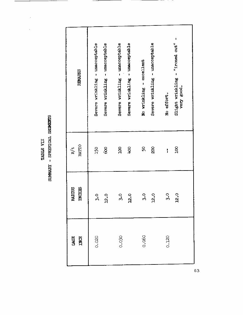
i. Spherical Segments. Prior to the forming of
the full scale task specimens, subscale 3.0-inch spherical radius
specimens were formed in the experimental punch and die equip-
ment illustrated in Figure 31. A split "G|assrock" heating unit
provided the necessary heat for the forming operation. During
the forming operation, the temperature was recorded by means
of thermocouples and a "Honeywell" 20-channel strip recorder.
Three circular blanks, 0.020 by 9.0-inches,
0.030 by 8.0-inches, and 0.060 by 7.0-inches were formed at
the nominal forming temperature of 1350°F. Since the radius
of the punch remained constant (3.0-inch) , the lqadius/thickness
(l_/t) rates of the formed hemispherical segments were _50, 100,
and 50 respectively. The results of these preliminary experiments,
illustrated in Figures 32 and 33, indicated that a R/t radio of
approximately 50 appeared to be satisfactory for the forming of
unsupported hemispherical segments. The severe edge crippling
that occurred at higher lq/t ratios is clearly visible in _he illustra-
tions. It should be emphasized that these results were very pre-
liminary, to be used only as a guide for the subsequent forming
operations.
53

/
I
H_a
H
n
I
n_a
n
H_
_o'_
H
54

F_H
I0
_oc_
ZH
I
_S
HI
0 0
0 r-I
c_
E-_Z
C3
HI
0
0I
Z
I0
_C_
_°
0
55

HI
0C_0
c_J
E_
_°
HH
Q
c_
c_
56

Due to the size of _he specimens to be formed
and the results of the initial investigation, a 12.0-inch spherical
radius, internally heated, "Glassrock" die was fabricated for use
during this phase of the program. The completed punch and die
set is illustrated in Figure 34.
Prior to the forming of any beryllium test speci-
mens, a "tool try" was made at room temperature with a 0.060
by lS.0-inch 61SO aluminum blank. The room temperature
characteristics and properties of 61SO aluminum are very similar
to those of berylhum at 1350°F; the use of the aluminum provides
an inexpensive means for checking the operation of tooling to be
used for the forming of beryllium. The aluminum hemispherical
test segment, and a 0.020-inch beryllium segment are illustrated
in Figure 35. The similarity of the wrinkles in the edges of the
t-cvo specimens should be noted.
All of the 18.0-inch diameter beryllium blank
specimens were preheated to 1350°F in an oven, located adjacent
to the forming die, before being manually transferred to the pre-
heated forming die. During the forming operations, the tempera-
tures were recorded by means of thermocouples and a Honeywell
20-channel strip recorder.
The wrinkling in the edges of the 0.020-inch,
0.030-inch and 0.060-inch test specimens was very similar to
that exhibited by the preliminary test specimens, but was pro-
gressively less severe. Prior to the forming of the 0. 120-inch
thick specimen, a 1.00-inch grid _ras scribed lightly on one
side of the blank in order to permit the measurement of the rela-
[ire shrinkage and s£retching of the material. The 18.00-inch
diameter blank and the formed spherical segment are illustrated
in Figure 36; the scribed inner surface of the spherical segment
is illustrated in Figure 37. It should be noted that the roughness
of the edge of the material, visible in the illustrations, was due
to the chemical process used in cutting the circular blank, and
not due to any forming reaction.
Critical visual examination of the 0.120-inch
thick formed specimens revealed no wrinkles or other deleterious
effects from the forming operation. The 0.120-inch thickness of
the material provided a l_adius/thickness (l:2/t) radio such ghat
any slight wrinkling fha_ may have occurred during the forming
57
4
t--I
HI
0
I
0
I-I
cI3o
cJ3
I--I
$8

NOTE : O. 020-INCH BERYLLIUM
NOTE: O.060-1NCH 61S0 'ALUMINUM
FIGURE 35. SPHERICAL SEGMENTS
O.020-1NCH BERYLLIUM AND O.060-1NCH 61S0 ALUMINUM
FORMED AT 1350°F AND ROOM TEMPERATURE, RESPECTIVELY.
NOTE THE SIMIIARITY OF THE WRINKLES AT THE EDGES
OF THE SPECIMENS.
59

Io
i-t_A
t-t
H
0
0 I
oZz
o
,dc%
0H
6O

FIGURE 37. SCRIBED INNER SURFACE OF THE FORMED SPHERICAL SEGMENT -
I.O0-1NCH GRID - O.120-1NCH MATERIAL - 12.0-1NCH RADIUS -
I00 R/t.
61

operation was "ironed out" by the punch as the die was com-
pletely closed.
Unfortunately, the failure of the die set, due
£o the fusing together of the punch and die during a preheating
cycle in the closed position, precluded the forming of the balance
of the specimens.
A summary of the results of this investigation
is presented in Table Vll. Both the initial 3.0-inch radius and
the final 12.0-inch radius data are included.
The measurement of the grid on the 0. 120-inch
thick spherical specimens revealed the maximum shrinkage and
elongation of the forming operation, were G and 5.5 percent re-
spectively.
The limited results of this preliminary study
indicate that for the forming of compound curves involving multi-
directional material flow and unrestrained edges, the maximum
R/t ratio and shrinkage appear to be 100 and 6 percent respective-
ly. The establishment of firm R/t ratios and shrink and stretch
values for all gages of material and a representative series of
diameters would require the accomplishment of a comprehensive
specialized development program which is not believed to be with-
in the scope of this study.
Following the completion of the forming of the
spherical segment specimens, the hemispherical gore segments
were to be formed in the same 12.0-inch radius punch and die
set. The complete failure of the tool precluded the accomplish-
sent of this minor portion of the program. However, since a
hemispherical gore is a sector of a hemisphere, and after care-
ful analysis and evaluation of the material flow pattern indicated
by the grid on the 0.120-inch thick specimens, it is believed that
the l_/t ratios and shrinkage values would be comparable to those
for the spherical segments.
2. Channel R.in_ Segments. Due to the combined
forming requirements _of minimum radius bends and compound
curvature, the development of suitable procedures for the form-
ing Of curved channel segments was the next logical step in this
forming program.
62
I
O-I_ I_
,-q ,M
l I
•rl .M
.M
r._ r._
,-_ ,M
l I
r._ r._
,M
c.l I
! oM
I
0
.el
I
.I-I
o _._ 4-_
.rt
O 8I
O O 0 0 O O 0 O
0
0
0c_0
c_
0',.00
c;
0
,-4
S
63

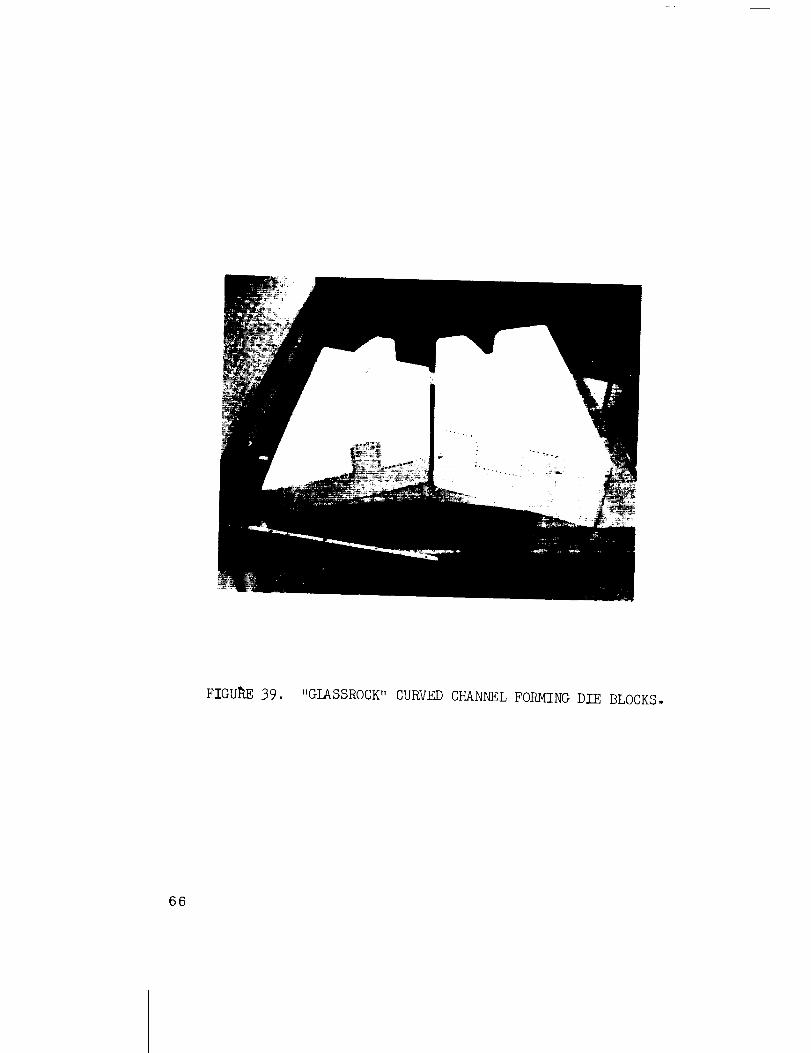
Again, due to the limited number of specimens
to be formed, the curved punches and the die were fabricated of
"Glassrock" and supported in steel frames for installation in the
press. Two punches, with bend radii of 0.30-inch and 0.60-
inch, were fabricated for the forming of the four gages of mate-
rial. The 0.30-inch radius punch was used for forming the 0.020,
0.030, and 0.060-inch material; the 0.60-inch radius punch was
used for forming the 0.120-inch material. The resulting cross-
section bend radii, therefore, were 1St, 10t, 5, and St, respec-
tively for the four gages of material.
The configuration and nominal dimensions of
the curved channels are illustrated in Figure 38. The completed
die and one of the punch blocks, ready for the installation of the
heating elements, are illustrated in Figure 39. The punch and die
clearances were nominal for the 0.060 and 0.120-inch materials;
copper sheets of appropriate thickness, placed on the die with
the beryllium blanks, compensated for the excess clearance that
would have existed during the forming of the 0.020 and 0.030-
inch specimens.
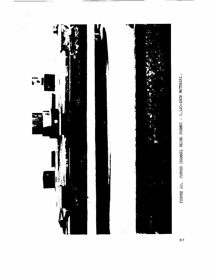
The blanks were preheated to 1350°F in an
oven, located adjacent to the forming die, before being manually
transferred to the preheated forming die. During the forming
operations, the temperatures were recorded by means of thermo-
couples and a Honeywell 20-channel strip recorder. The forming
of one of the 0. 120-inch specimens is illustrated in Figure 40.
A specimen blank and representative curved channels are illustrat-
ed in Figure 41.
The effects of excessive clearance or lack of
die support are clearly visible in _his figure. The 0.020-inch
thick channel was formed with the proper 0.040-inch thicknes_
of copper sheet material. The slight waviness of the edge of
the o,T_r flange was. due to lack o_ suppor_ at _he very edge;
the flange extended slightly above the tangent of the die radius.
The same condition is exhibited by the 0.060-inch thick channel
specimen. As illustrated by the 0.120-inch thick specimen, this
edge is removed during the final trimming operation. The effect
of excessive punch -die clearance is illustrated by the 0.030-inch
thick channel specimen. This particular channel was formed with an
0.018-inch thick spacer sheet rather than _he required 0.030-
inch thick sheet. The utilization of a spacer of the proper
64

0
H
4
I
0HE_
I---t
0
4
r.D
dc%
SH
65
FIGU_E 39. "GLASSROCK" CURVED CHANNEL FORMING DIE BLOCKS.
66
I
o
ZH
I0
c_I
0r_
H
c_
c_
c_
H
67

68
i
C_
HE_
E_
H
c_
C_

thickness alleviates this problem.
It should be noted that the slight unevenness of
the curved edges of the blank was due to the chemical process
used in cutting them.
In order to determine the materia£1 flow pattern,
a 1.00-inch grid was scribed lightly on one side of one of the
0.120-inch blanks prior to the forming operation. The displace-
sent of the grid lines and the appreciable variation in the height
of the flanges is clearly visible in Figure 42. It should be stated
that a portion of this variation in flange height is believed due to
the shearing of the punch locating pins during the forming operation;
the beryllium blank was displaced slightly during the actual forming
cycle. The shrinkage and elongation of the material decreased
progressively from the maximum of 4 percent of the midpoint
(midlength), to less than 1 percent at the ends.
The results of this portion of the forming
development program indicate that the forming of curved channel
segments on a production basis is entirely feasible, and that
existing punch and die sets may be utilized if spacer sheet
material is used to compensate for any excessive clearance that
may exist. The maintenance of the nominal forming temperature
of 1350°F throughout the forming operation is mandatory. A
steady punch travel rate, not exceeding I inch per minute, is
suggested.
Furthermore, the low shrinkage and elongation
indicate that the forming of curved channels of smaller arc radii
is entirely feasible. Since most of the required material flow is
in the plane of the sheet material, where slippage along the basal
planes is most readily accomplished, significant dimensional
changes may be anticipated.
3. Deep Drawing. The drawing of beryllium can
be accomplished on a limited basis under carefully controlled
conditions. I-Iowever, the extreme abrasiveness of the material
at forming temperatures, the lack of a suitable lubricant, and
the availability of other more suitable forming methods preclude
its extensive use at the present time. Therefore, due to its
limited application and the inherent manufacturing problems, no
69

0
H ZH
_o_E-4
H
©
r'-I
0
A_0
H
O00
I
N _co_H
0c__;_
...q-
0H
70

additional work was included in this development program. Only
previous experience, as stated in the Program Plan, is reported.
During a very limited development program,
conducted approximately 2 years ago, the feasibility of limited
drawing of beryllium was demonstrated. During the initial form-
ing operation, the even heated (1300°F) 0.290-inch thick by 9.5-
inch diameter vacuum hot pressed block blank was successfully
"cupped t' 1.36-inch deep at a rate of approximately 0.3-inch
depth of draw per minute.
/in improved die, incorporating integral heating
units, was fabricated for use during the subsequent forming oper'a-
tions. Several specimens, cut from 0.064-inch thick cross-
rolled sheet material were successfully formed. The 9.5-inch
diameter blanks were heated in an oven to a temperature of
1300°F rrianuallytransferred to the die and drawn at ra_es of
approxir_ately 0.2 to 0.4-inch per minute. The nominal final
diameter and n_aximum uepth attained were 6 inches and 2.87
inches respectively. It should be stated that this depth was
accomplished in two stages; the maximum depth attained without
failure, during a single stage was 1.3 inches. Unfortunately,
severe Railing occurred on the external surfaces of all of the
specimens. _Fhe effects of various lubricating materials, were in-
vestigated. Although a slight improvernent was observed, none
of these materials was satisfactory, and as stated before, a suit-
able lubricant for beryllium has yet to be developed.
The results of this early development work
indicate that beryllium can be moderately formed by drawing,
i.e., hemispheres can be formed by this method. However, the
inherent characteristics of the material at high temperatures, the
lack of a suitable lubricant, the necessity for extremely close
control of drawing pressures, and the subsequent development of
the simpler more straightforward forming procedures reported
herein appear to preclude fu1*ther development of the drawing
process as a beryllium method.
C. JOGGI.ING
Although the ioggling of aluminum, steel, etc., angle
has long since become a routine production forming process, the
inherent characteristics of beryllium have inhibited the application
71
of the process to this material. The joggling of the angle stock
normally is a re-strike operation during which areas of the part
are shaped by the displacement and repositioning of the material.
The requirement for dimensional changes in the plane of the
material has presented the greatest deterrent, and little or no
development work has been accomplished.
The objectives of this portion of the development
program, therefore, were the verification of the feasibility of
the process, as applied to beryllium, and the establishment of
preliminary forming parameters.
Due to the previous failure of the "Glassrock I' dies
and the availability of the hydraulic press brake and standard
adjustable steel joggle dies, this portion of the program was
accomplished on this standard production equipment. Since the
nominal 1000°F limit of the standard conduction heated joggle dies
was too low, high intensity quartz lamps with l'Glassrock" re-
flectors were utilized to provide the necessary supplementary
heating to raise the temperature of the dies to the required beryl-
lium forming temperature of 1350°F. However, due to the heat
loss by radiation, the heat sink effect of the steel die blocks, and
the necessity for withdrawing the lamps several inches to pro-
vide clearance for the ram during actuation of the press, the
maintenance of the desired temperature of 1350°F was extremely
difficult. ]_ven the momentary withdrawal of the lamps during
the actuation cycle of the press frequently resulted in a specimen
temperature drop of 50-100°I e, at the actual instant of joggling.
During the joggling operations, the temperatures were recorded
by means of thermocouples and a Honeywell 20-channel strip
recorder. The press platen, adjustable joggle die blocks, the
quartz lamps and a pair of beryllium angle specimens ready for
forming are illustrated in Figure 43.
In order to establish acceptable joggle depth to
transition ratios, a transition length was arbitrarily selected for
each material gage and the joggle depth was varied. A summary
of the results of this investigation are presented in Table VIII.
The analysis of the information and data presented
in the table verified the feasibility of joggling as a beryllium form-
ing process. The fractures that occurred during the joggling
operations _'ere due either to incorrect material temperature
72

co
A
_c_
ul
OH
73

r._
o o o o ,$0_ --, = ,$ o o o o o o o o0o -_" _ 0 0 _ --_ o.I
I .._ o_ _ 0 _ _ --.-1" _ _ _ rd -.a" ".O -.a" 0r--I r--t _ c_ C_ o'_ _ c_ -..1" _ 0 0 c_ .._ 0
___ 0 0 0 0 0 0 0 0 o 0 0 0 O. 0 0
_0 _'- 0 H 0 _0 ".0 _ ..0 _ 0 0_ _ _ 00 0 r-I ,--I ,--I ,--I _-I C_ C_ O_ 0 0 ,--I 0,_ 0
•_ 0 0 0 0 0 0 0 0 0 0 0 0 0 0 0,_ d d d d d d d d d d d d d d d
0 r.-.-I r-"l ",.O _ 0 C_ .--I "...0 r'-I 0 0", 03 0",
0 0 0 0 0 0 0 0 0 r--I 0 0 0 0 0
d d d d d d d d d d d d d d d
0 0 0 0 0 0 0 0 0 0 0 0 0 0 0
d d d d d d d d d d d d d d d
Izl
V
r
0 0 0 0 0 0 0 0 0 00,_ O_ 0 0 0 0 0o o 8 _o o_ oTM _ _ _ _ _ _.. o o o o o o _ _ _o d d d d d d d d d d d d d d
74

c) r_3
HHI I
O I
HI-I
o
I-i
@) ® ®®
Q Q Q Q 0
o o o(k_ oJ oJO_ (_ o_
o d JI I I
0"- cq too o oo o o
d J d
o _ r-t
O o O
o o o
o o oc_ c_ c_
J d J
o O o
o o o
d d o
v v r-I
_ _ 0_ _ +_
0 0 0 0
+_
o _ Q _ © o
o o o_-I _-I --f0_1 _1 (_,-4 _-t ,-I
o
_J
o
4._0
¢1
o
0 u_ u-x Lr_ L_ 0 0 0.-1" ...1" ..q" 0_, O_ 0.1 0
_--I r--I H ,--I H _-I H r'-I
_..1- o"- o o,1 r-I to r-I on .-4" -..1" r-'-IO O O,1 _ O'h -.4" _ U-'-, O O CqO O O O O O O O O O O
,4 d d d o d o d o d d,y I I I I I I I I I I
c,q o u-,,, _ _ u-h o'h r--I O r--Io 0 r-'l H H r'_ r-t 0q 0 0 r_O O O O O O O O O O O
j d d d d d d d d d d
u-,, w-, o,i_...1- u-x,0 o o
d d o
,4) u--, _ O--. O,1 O_ b.- or-,,u-',, -.-1 ---t ',O _ or,,, _0O O O O O O O O
j d d o d d o d
o o oc,h 0'h cq
d d d
O O O O O _ _ umc,q oq o"h cq cq b- b- b,.-
d d d d d d d d
o o< _r-'l r-I _ _ r"-'l r-I _-I r-I
o o o0q 0q 0_o o o
d d d
O O O O O O O O
o'h cq _ cq c'q, ,-.D "...O 'qDO O O O O O O
J o o d d d d d
oQ
Q
0
0
_'_0b..- L_
JdOOE-_E_
HH
_z
bib
C_ --.¢
,-(j
H _
r--t
o ..,_
o _-qo _
d _
I"_ oo
O I
oo
b"-I
c----
I
r-t0_
o
o
o No
"/5

{substantially less than the optimum forming temperature of 1350 °
F), or to insufficient displacement of the leg of the angle during
the joggling operation. In the majority of the cases, if the dis-
placement was less than 25 percent of the depth of the joggle,
failure occurred in the bend radius of the angle. This lack of
leg displacement is believed due to the scale that formed on the
die segments, which interferred with the free movement of the
leg during the joggling operation, and resulted in the "pinching"
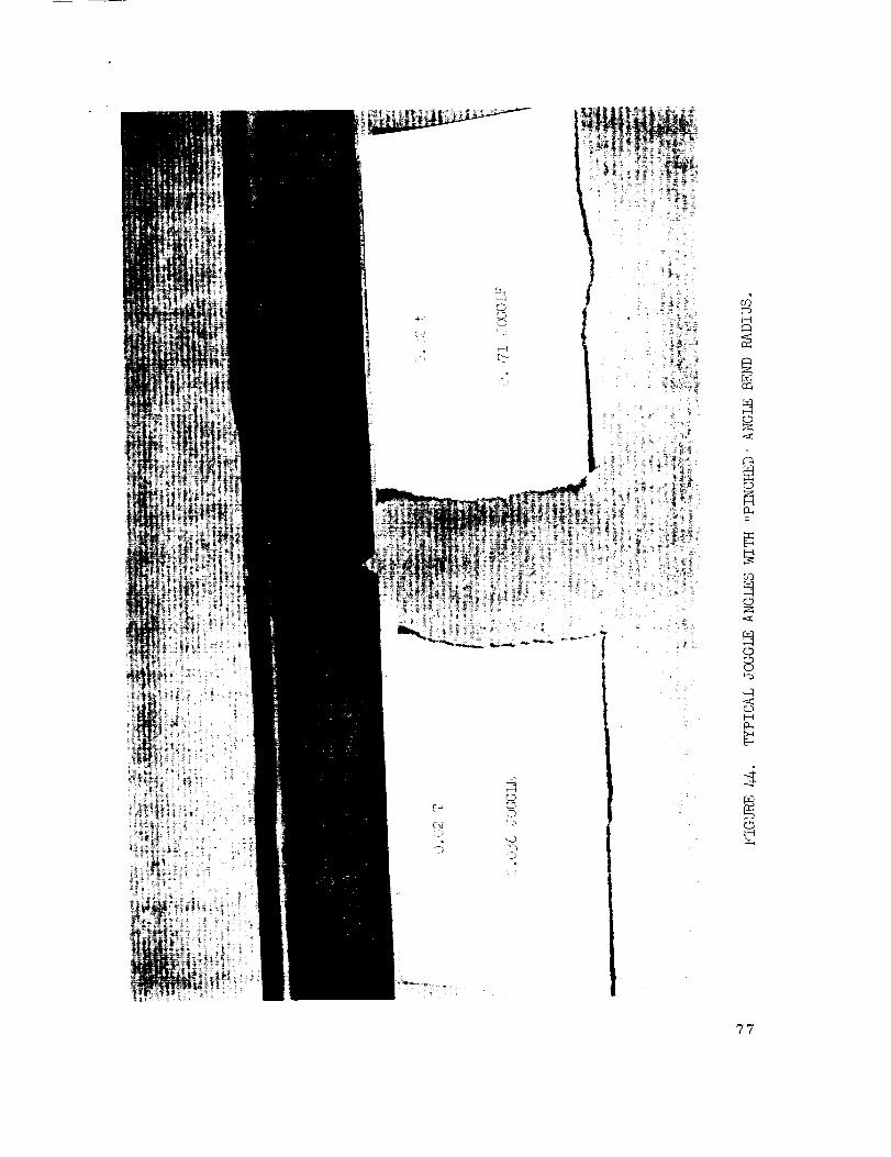
of the bend radius. The effect of this insufficient movement of
the leg of the angle and the resulting pinching of the bend radius
angle are illustrated in Figure 44. The use of stainless steel
matched die sets, instead of the standard adjustable die set used
during this program, should alleviate this problem. !_epresentative
satisfactory joggled specimens are illustrated in Figure 45. The
smooth transition and lack of bend radius "pinching" should be
particularly noted.
In conclusion, the results of this phase of the pro-
gram indicate that the joggling of beryllium angles on a production
basis is entirely feasible, and that existing equipment can be
utilized if nominal transition lengths and joggle depths of approxi-
mately 10-12t and i-2t, repsectively are utilized. The main-
tenance of the nominal forming temperature of 1350°F throughout
the forming bperation is mandatory. In addition, the use of stain-
less steel matched die sets, rather than a standard adjustable die
set, is highly recommended.
SECTION IV. CONCLUSIONS AND RECOMMENDATIONS
The results of this investigation clearly verified the
feasibility of forming structural shapes of cross-rolled beryllium
sheet material. Both "straight bend" and "compound curvature"
forming can be successfully accomplished if the details of the
processes are carefully observed.
The maintenance of the proper material temperature
during the entire forming cycle is mandatory. Even relatively
small variations that would be of little or no importance in the
forming of "conventional" materials_ may inhibit the successful
forming of beryllium.
76
u_H
c_
J_
C_H
_H
77

_°
o .
c_O
4J
O
rD
c_
O
M
O
00
O
O,..0,O
'-.00_O
M
O
H
O
r _,
r_
c_
H
H
z_<
(D (D
cQ
CO
m (D
-4"
OH
?8

The results of these limited investigations indicate the
foilowing conclusions and recommendations:
a_ The optimum forming temperature appears
to be 1350 ± 25°F.
b , The minimum radius bend for all gages of
beryllium sheet material up to 0.120-inch
in thickness is 5t.
C Although very thin gages of beryllium up to
approximately O.030-inch in thickness can
be formed to a 4t radius, this radius is
not recommended.
d , The use of the conventional "punch and die"
type of equipment for the forming of channel
sections is acceptable if the temperature is
carefully controlled throughout the length of
the die, and if appropriate means, such as
stainless steel buffer plates, are utilized to
prevent the galling of the surface of the beryl-
lium.
e In order to avoid high stress levels, the
double-action type of "punch and die" equip-
ment is recommended for the forming of hat
sections .
2. It is believed that the use of appropriately
designed "folding type" equipment will be
the most economical means for the pro-
duction forming of straight bend sections
including angles, channels, zee and hat
sections. The maintenance of even temper-
ature throughout the workpiece during the
entire forming cycle is mandatory.
g , Additional "straight bend" forming work is
recommended. Although the forming of
representative sections by various methods
has been demonstrated, the establishment
of firm minimum bend radii for all gages
79

h •
i,
k ,
le
of material, and the determination and
refinement of the most appropriate method
for the production of each specific cross-
section, are required.
Due to the necessity for heated rolls with
precise temperature control, the difficulty
of maintaining the proper forming tempera-
ture throughout the _rorkpiece, the high
cost of the "scrap ends H and of the steel
sandwich material, and the subsequent
stress-relleving operation in specialized
equipment, rolling is not recommended as
a forming procedure.
The use of a heated die press is recommen-
ded for the forming of parts having a large
radius•
The maximum permissable lq/t ratio and
shrinkage appear to be 100 and 6 percent
respective]y for the forming of compound
curves, involving multi-directional material
flow and unrestrained edges.
The forming of hemispherical sections on
a production basis is entirely feasible with
properly designed "punch and die" type of
equipment. ]_xact temperature control and
precise clearance tolerances must be in-
corporated in the equipment.
The forming of curved channel sections on
a production basis is entirely feasible with
existing "punch and die" sets if the correct
thickness of spacer sheet material is used
to compensate for any excessive clearance
that may exist. The maintenance of the
proper temperature throughout the work-
piece during the forming cycle is mandatory.
A steady punch travel rate_ not exceeding 1
inch per minute_ is recommended.
8O
APPROVAL NASA TM X- 53453
THE FABRICATION OF BERYLLIUM ALLOYS - VOLUME II.
FORMING TECHNIQUES FOR BERYLLIUM ALLOYS
The information in this report has been reviewed for
security classification. Review of any information concerning
Department of Defense or Atomic Energy Commission Pro-
grams has been made by the MSFC Security ClassificationOf_ic e r.
This report, in its entirety, has been determined to be
unclassified.
W. A. WILSON
Chief, Methods Development Branch
JC"i/el: MC)2n_facturing Research and
Technology Division
_WERNER R. I<UERS
Director, Manufacturing Engineering
L abo rato ry
82

m.
n °
o .
p .
q .
Additional compound curvature forming
work is recommended. Although the
feasibility of forming various compound
curves has been demonstrated, the
establishment of firm lq/t ratios and
shrink and stretch values, for all gages
of material and a representative series
of diar_eters or sizes, have not yet
been accomplished.
Deep drawing is not recommended for the
fornqing of beryllium.
The feasibility of _oggling beryllium angles
has been demonstrated. The use of stain-
less steel matched die sets is highly re-
comrrlended to avoid the "pinching" of the
bend radius. ;qeating equipment, with
precise temperature control, must be an
integral part of the die set.
The use of similar stainless steel matched
die sets should permit the $oggling of
channel sections.
Additional joggling development work is
recommended. Although the feasibility
of )oggling angles has been demonstrated
and the feasibility of joggling channel sec-
tions is indicated, further investigation and
development of the processes are required.
The determination of firm transition lengths
for all gages of r_aterial and representative
sizes of sections, the _evelopment of exact
controls, the establishment of routine pro-
duction procedures, and the design of suit-
able stainless steel matched die sets have
not yet been accomplished.
81