Embed Size (px)
Citation preview

Packmaß
Befestigungsösen
verst. Schiebegriffe
Seitenteile
Antriebseinheit
Skip
pi
BedienungsanleitungInstructions for Use
Skippi

54

55
Instructions for Use for the Skippi
1 Table of Contents.................................................... 552 Preface................................................................... 573 Range of Application .............................................. 574 Declaration of Conformity ....................................... 585 Service ................................................................... 586 Symbol Legend....................................................... 587 General Safety Precautions .................................... 598 Transport und Lagerung.......................................... 62 8.1 Transport in a Motor Vehicle for the Disabled.................................................... 62 8.2 Disassembling the Skippi Power Wheelchair for Children ............................ 63 8.3 Delivery ..................................................... 669 Adjustment Possibilities........................................... 67 9.1 Back ......................................................... 68 9.2 Seat Angle Adjustment.............................. 68 9.3 Armrest ..................................................... 69 9.4 Control Panel ............................................ 69 9.4.1 Removing the Control Panel ...................... 69 9.4.2 Adaptation to the Arm Length.................... 70 9.4.3 Footrest..................................................... 7010 Getting Into and Out of the Wheelchair .................. 71
10.1 From the Side............................................ 72 10.2 From the Front........................................... 7211 Putting into Operation............................................. 73 11.1 Hand Control Device................................. 73 11.1.1 On/Off Button........................................... 74 11.1.2 Mode Button ............................................. 74 11.1.3 Horn.......................................................... 74 11.1.4 Warning Flasher........................................ 74 11.1.5 Light.......................................................... 75 11.1.6 Direction Indicator, right ............................ 75 11.1.7 Direction Indicator, left .............................. 75 11.1.8 LCD Display.............................................. 76 11.1.9 Driving Menu ............................................. 77 11.1.10 Battery Indicator ....................................... 78 11.1.11 Electric Seat Functions ............................. 79 11.1.12 Drive-away Lock ....................................... 80 11.2 Brake Release........................................... 82 11.3 Batteries ................................................... 83 11.4 Fuse.......................................................... 84 11.5 Battery Charging ...................................... 85 11.5.1 Charging Process ..................................... 8612 Status and Error Indication ..................................... 88

56
13 Options ................................................................. 92 13.1 Control for Attendant................................. 92 13.1.1 On/Off Button........................................... 93 13.1.2 Battery LED .............................................. 93 13.1.3 Mode Button ............................................. 94 13.1.4 Mode LED................................................. 94 13.1.5 Electric Seat Functions – Control for Attendant................................. 95 13.1.6 Status/Error Indication – Electric Seat Functions ............................. 96 13.1.7 Switch-over Function – Control for Attendant/ Hand Control Device................................. 96 13.1.8 Error Indication – Control for Attendant..... 97 13.2 Control Panel, swing-away ....................... 97 13.3 Lap Belt .................................................... 97 13.4 Seat Options............................................. 98 13.4.1 Electric Seat Tilt ........................................ 98 13.4.2 Mechanical Seat Tilt ................................. 98 13.4.3 Electric Back Angle Adjustment ................ 98 13.5 Other Options ........................................... 9914 Maintenance, Cleaning and Care ......................... 100 14.1 Maintenance ........................................... 100 14.2 Care ....................................................... 101 14.3 Cleaning and Disinfection ....................... 101
15 Disposal ................................................................ 10216 Technical Data – Skippi......................................... 10317 Technical Data – Battery Charger......................... 10418 Liability.................................................................. 104 18.1 Liability for Power Wheelchairs ............... 104 18.2 Incidental Provisions................................ 10419 Information regarding Re-Use ............................... 105

57
2 Preface
The Skippi Power Wheelchair for Children is a quality product offering versatile use in everyday life. The main special features of the Skippi are:
• Compact design • Easy operation • Easy to disassemble for transport • Easy to service due to modular component group concept • Easy access to all component groups
Before using the power wheelchair for children, please read these Instructions for Use thoroughly, especially the Safety Instructions in Sek.tion 7, and talk them over and explain them with/to your child. The model as described in these Instructions for Use is subject to technical changes without notice.
3 Range of Application
The Skippi Power Wheelchair for Children is designed solely for children and small people who are unable to walk or who have a walking impediment for control by the patient themself. The Skippi was specially designed for individuals who are able to independently move in a power wheelchair for children. Skippi is a power wheelchair for children for indoor use according to category A of EN 12184 standard. With regard to the climate and splash-proof test, the Skippi also ful� lls the requirements for outdoor use. Thanks to its quick and easy adjustment possibilities for standard � ttings and the modular design, the Skippi can be used by patients with walking impediments/inability due to: • Paralyses • Loss of limbs • Defective or deformed limbs • Joint contractures or defects • Other diseases

58
Fitting considerations: • Body height and weight (maximum load 50 kg) • Physical and psychological limitations • Age of the patient • Living conditions and environment
4 Declaration of Conformity
Otto Bock HealthCare as manufacturer with sole responsibility declares that the Skippi Power Wheelchair for Children conforms to the requirements of the European Directive for Medical Products 93/42/EEC.
5 Service
Service and repairs on the Skippi may only be carried out by authorized dealers. Should any problems arise, please contact your wheelchair supplier.
Your authorized Otto Bock dealer:
Note!Please ensure that your Skippi power wheelchair for children is checked and serviced at least ONCE a year by an authorized dealer!
6 Symbol Legend
Danger!Warning regarding possible risks of accident or injury.
Caution!Warning regarding possible technical damages.
Note!Information for operating the product.

59
7 General Safety Precautions
Please observe the following general safety instructions at all times:
Danger!Children using the power wheelchair should not be left unattended.
Danger!The Skippi may be used for transporting only one person.
Danger!To avoid potentially dangerous situations such as tipping, user and attendant must become familiar with the power wheelchair for children on level ground first.
Danger!When getting into or out of the power wheelchair for children, the wheelchair control must be switched off.
Danger!The footplates must not be used when getting into or out of the power wheelchair for children.
Danger!Get to know with assistance from another person how the power wheelchair reacts when the center of gravity is shifted, i.e. when driving on slopes or inclines or clearing obstacles like steps and curbs.
Danger!When using the wheelchair on inclined surfaces ensure the automatic brakes are operating correctly.
Danger!Use the wheelchair properly. For instance, do not drive against obstacles (including steps, curbs or doors) without braking first. The critical obstacle height is 5 cm. Therefore, driving over steps or curbs higher than 5 cm is not allowed.

60
Danger!Be careful with any naked flames and cigarettes, as the back upholstery and seat cushion could catch fire.
Danger!The maximum load for the Skippi power wheelchair for children is 50 kg.
Danger!The driving characteristics of the Skippi power wheelchair for children can be influenced by electromagnetic fields as emitted by mobile phones or other radiating devices. For this reason, all mobile devices must be switched off when driving.
Danger!It is also possible that the Skippi itself generates electromagnetic fields that might cause interference in other devices. Therefore, switch off the control whenever you do not need it.
Danger!Ensure the tires are in good order and condition and check that they are inflated to the correct tire pressure (printed on the sidewall of the tire).
Danger!The Skippi may be used within a temperature range from -25°C to +50°C.
Danger!The Skippi is not suited for driving on very slippery (such as icy) surfaces or on very coarse-grained ground such as gravel, pebbles, shingle or scree.
Danger!The Skippi has been approved for ascending or descending inclines of up to 12%.
Danger!When using lifting platforms, ensure that the anti-tipper is outside the danger-area.
Danger!When using the wheelchair on lifting platforms or elevators the wheelchair control must be switched off and the brake must not be released.
Danger!During battery charging, the control must be switched off.

61
Danger!For safety reasons, a lap belt can be attached, which is optionally available.
Danger!Never use a water hose or high-pressure cleaning apparatus for cleaning the wheelchair. Direct contact of water with the electronics, motor and battery must be avoided.
Danger!Be careful not to injure your fingers during adjustment and assembly.
Danger!Defective batteries must be disposed of properly. They can be returned to the dealer when buying a new one.
Hinweis!Die Aktuatoren sind nicht für Dauerbetrieb, sondern für eine 10%ige Belastung ausgelegt. Bei einer Betriebsdauer von 1h kann also die Aktuatoren-funktion max. 6 Minuten lang betätigt werden.
Gefahr!Überlastung der Aktuatoren kann zum Bruch der Spindelmutter und somit zum Absacken des Sitzes, bzw. zum Zurückklappen des Rückens führen.
Gefahr!Den Rollstuhl nur an Rahmenteilen anheben! Auf garkeinen Fall an Fußstützen oder Armauflagen anheben!
Hinweis!Bei längeren Standzeiten oder starker Erwärmung der Reifen (z. B. in der Nähe von Heizkörpern oder Sonneneinstrahlung durch Glasscheiben) kommt es zu einer bleibenden Verformung der Reifen. Achten Sie deshalb stets auf genügend Abstand zu Wärmequellen, bewegen Sie Ihren Stuhl des Öfteren oder schaffen Sie sich bei Einlagerung die Möglichkeit des Aufbockens.

62
Fig. 1 Fig. 2
8 Transport and Storage
The Skippi can be transported both as power wheelchair for children, ready to start, or in disassembled condition (Fig. 1, 2). During transport the wheelchair must be fully Sek.ured by means of tension straps. The frame of the Skippi power wheelchair for children has four fixing eyelets for the attachment of straps (Fig. 3, 4).
The temperature during transport and storage must be between -25°C and +50°C. The wheelchair control must be switched off and the brake engaged during transport.
Bereifungen enthalten chemische Stoffe, die mit anderen chemischen Stoffen (wie z.B. Reinigungsmittel, Säuren, etc.) eine Reaktion eingehen können.
8.1 Transport in a Motor Vehicle for the Disabled
We recommend that, wherever and whenever possible, users of a wheelchair/ mobility base with seating shell or
Fig.3 Fig.4
Achtung!Sollte ihr Rollstuhl einige Tage nicht bewegt wer-den, so können sich unter Umständen permanente, farbliche Veränderungen an den Kontaktstellen zum Boden abzeichnen. Wir empfehlen deshalb, bei längerer Standzeit für eine geeignete Unterlage zu sorgen.

63
Fig. 5 Fig. 6
buggy transfer to the seats installed in the motor vehicle and use the corresponding vehicle restraint systems, because this is the only way to ensure optimal protection of the passengers in case of an accident. For the time being, Otto Bock has not yet released the Skippi Power Wheelchair for Children for use as a seat for transportation in motor vehicles; the release is currently being prepared, however. If need be, please ask for information on the current state of our measures under the following address: Otto Bock HealthCare GmbHMax-Näderstr.1537115 DuderstadtTel.: +49 (0) 5527/848-1461Fax: +49 (0) 5527/848-1460E-mail: [email protected]
8.2 Disassembling the Skippi Power Wheelchair for Children
To reduce the folding size for transport of the power wheelchair for children, it can be easily disassembled.
Gefahr!Ihr Rollstuhl ist im momentan für die Nutzung in einem BTW noch nicht freigegeben!

64
Please observe the following order for disassembly:1. Remove the footrests (Fig. 5).2. Take off the control panel and carefully deposit it on the
ground beside or behind the wheelchair (Fig. 6).3. Remove the side panels (Fig. 7).4. Fold the backrest down to the front (possible only with
manual back adjustment) (Fig. 8).5. Loosen the drive unit from the seating unit by
simultaneously pulling the hook and loop strap and folding the locking bar to the rear (Fig. 9).
7. To separate the frame from the drive unit sustainer, step on one of the bumper wheels above the anti-tippers so that the anti-tippers touch the ground (Fig. 12).
Then separate the frame from the drive unit sustainer by slightly lifting the frame and pulling it to the rear.
To reduce the space needed, the two battery packs can be replaced into the drive unit sustainer. To prevent the battery packs from falling out of the drive unit sustainer, the locking lever must be relocated (Fig. 10).
The control panel can be put on the battery packs (Fig. 11).
Fig. 7
Fig. 9
Fig. 8
Fig. 10
Fig. 11 Fig. 12

65
Ensure that the control panel remains switched off and that no cables are pinched.
8. With the option of “height-adjustable push handles”, loosen the quick clamps and move the handles down as far as possible. If need be, swing them inwards (Fig. 13).
For re-assembly of the Skippi power wheelchair for children the steps described above must be carried out in reverse order.
Fig. 13

66
8.3 Delivery
Upon delivery by the dealer the Skippi is ready for use. All settings have been made in accordance with the indications on the order form or are made directly on site by the dealer. Thus, the Skippi is adapted to the personal requirements of the individual.
Before using the wheelchair, all components of the standard equipment must be checked for completeness (Fig. 14):
1. Backrest 2. Armrest with lateral pad 3. Joystick & control unit 4. Seat cushion 5. Footrest 6. Motor & drive wheel 7. Anti-tippers and bumper wheels 8. Locking lever
The functions of the individual components are to be verified according to the indications in the Sek.tions “Disassembling the Skippi Power Wheelchair for Children”, “Adjustment Possibilities” and “Putting into
Fig. 14
31
2
7
65
8
4

67
Operation”. Should any problems arise, please refer to the Sek.tion “Status and Error Indication”. The tool kit, an optional accessory, contains a set of Allen wrenches (3, 4, 5 and 6 mm) and one open-end 13 mm wrench (und eine Luftpumpe).
9 Adjustment Possibilities
Skippi’s seat width as well as the seat and back position may only be set and changed by the dealer. All other settings such as: seat depth, seat and back angle, armrest height and lower leg length, as well as the disassembly of the footrests and armrests can be done by the user with the tool kit, which is optionally available, or by hand.
Disassembly of the Skippi power wheelchair for children can be easily done by an attendant (see Sek.tion 8 Disassembling the Skippi Power Wheelchair for Children).

68
Fig. 16
9.1 Back
The back can be adjusted to four different angle positions by pulling the release strap which is located at the base of the back. Once the back is in the desired position, release the strap to engage the locks (Fig. 15).
9.2 Seat Angle Adjustment
The Skippi offers 3 different seat angle settings (-6°, 3° and 12°). To change the position, swing away the Sek.uring bow of the tube quick lock pin and pull out the pin (Fig. 16).
Note!Ensure after every seat angle adjustment that the Sek.uring bow of the pin has been closed!
Note!During seat angle adjustments the user must not sit in the wheelchair.
Fig. 15

69
9.3 Armrest
The armrests can be removed by loosening the thumb screws at the lower end of the armrests and lifting the armrests upwards (Fig. 17). The height of the armrest can be changed by loosening the screw at the upper end of the armrest holder (Fig. 18).
Ensure the screw is firmly retightened after making any adjustments. Both armrests can be removed, however, only the side without the control panel can be removed directly. Before removing the armrest on the side with control panel, the control panel must be removed.
9.4 Control Panel
9.4.1 Removing the Control Panel
The control panel is held in place by a simple spring sheet metal and can be removed by pulling it to the front (Fig. 19).
Fig. 19
Fig. 17 Fig. 18

70
9.4.2 Adaptation to the Arm Length
After loosening the attachment screws on the bottom of the armrest, the control panel can be shifted forwards or backwards and can thus be adjusted to the desired arm length (Fig. 20).
9.4.3 Footrest
The footrest is easy to remove. As shown in the photo (Fig. 21), you just have to press the safety pin and remove the footrest by pulling it up. For mounting, put the footrest from above in the holding device, press the pin and turn the footrest until it engages.By loosening the screws on the telescoping footrest tube at the front and rear, the footplate can be adapted to the lower leg length and to the thickness of the child’s seat cushion (Fig. 21).The angle of the footplate can be changed by loosening the attachment screw on the rear of the footrest bar (Fig. 22).
The footrest receivers can be telescoped in longitudinal and transverse direction. Telescoping in longitudinal direction takes place in pairs: Loosen both screws and
Fig. 21
Fig. 22
Fig. 20

71
move the footrest receivers on the seat plate to the desired position. Afterwards, firmly retighten the screws (Fig. 23).In transverse direction, telescoping is possible independently from each other (Fig. 24).
Note!Make sure to firmly retighten all screws and nuts after making adjustments.
10 Getting Into and Out of the Wheelchair
Thanks to the modular design of the Skippi power wheelchair for children, it is easy to get into and out of the wheelchair. The armrests and footrests can be removed easily and thus allow easy access for transfer from the side or from the front.
(Abb) D2_3590 (Abb) D2_3574
Fig. 23 Fig. 24
72
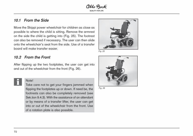
10.1 From the Side
Move the Skippi power wheelchair for children as close as possible to where the child is sitting. Remove the armrest on the side the child is getting into (Fig. 25). The footrest can also be removed if necessary. The user can then slide onto the wheelchair’s seat from the side. Use of a transfer board will make transfer easier.
10.2 From the Front
After flipping up the two footplates, the user can get into and out of the wheelchair from the front (Fig. 26).
Note!Take care not to get your fingers jammed when flipping the footplates up or down. If need be, the footrests can also be completely removed (see Sek.tion 9.4.3). With the assistance of an attendant or by means of a transfer lifter, the user can get into or out of the wheelchair from the front. Use of a rotation plate is also possible.
Fig. 26
Fig. 25

73
11 Putting into Operation
The wheelchair control can be adapted to your personal requirements. Please contact your trained dealer, who will carry out the programming.
11.1 Hand Control Device
The hand control device consists of button Sek.tion, LCD display and joystick. In addition, there is a charging/ pro-gramming receptacle on the underside.Position / Description
1 On/Off2 Display3 Mode button4 Horn5 Direction indicator, left6 Light7 Direction indicator, right8 Warning flasher9 Joystick10 Charging receptacle (underside of control panel)
3
4
7
6
9
5821
10

74
11.1.1 On/Off Button
The On/Off button is located above the display. The button is used for switching the power wheelchair on, for activating the drive-away lock and for switching the wheelchair off.
11.1.2 Mode Button
Pressing the mode button (located below the display in the middle) shortly, increases the speed level. After reaching the maximal speed level, the next press on the button will change back to speed level 1. Pressing the button for longer than 2 Sek.onds switches the control to the “Electric seat functions” menu. For more information see Sek.tion 11.1.11 “Electric Seat Functions”.
11.1.3 Horn
The button for the horn is located below the display on the right. As long as this button is being pressed, the horn will sound.
11.1.4 Warning Flasher
Pressing the warning flasher button activates all four direc-tion indicators. If the wheelchair control is switched off, the warning lights will continue to flash.
75
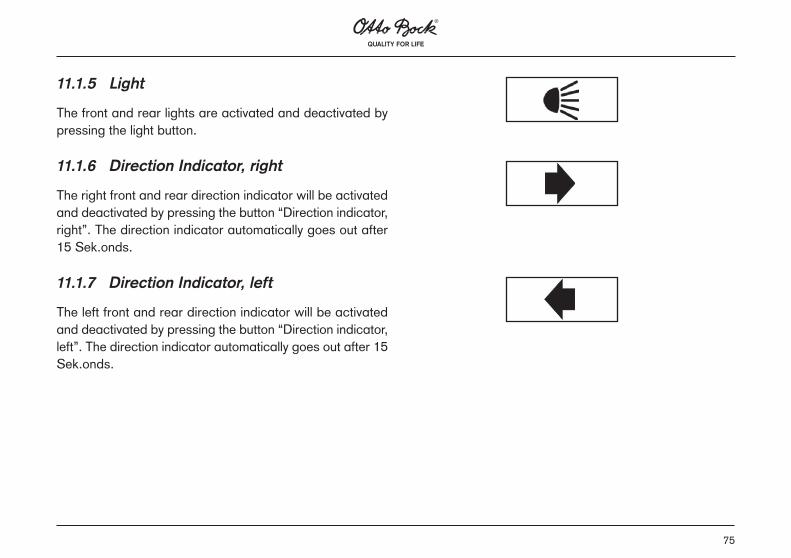
11.1.5 Light
The front and rear lights are activated and deactivated by pressing the light button.
11.1.6 Direction Indicator, right
The right front and rear direction indicator will be activated and deactivated by pressing the button “Direction indicator, right”. The direction indicator automatically goes out after 15 Sek.onds.
11.1.7 Direction Indicator, left
The left front and rear direction indicator will be activated and deactivated by pressing the button “Direction indicator, left”. The direction indicator automatically goes out after 15 Sek.onds.

76
11.1.8 LCD Display
The LCD display is the communication interface between user and control unit and indicates the selected speed level, the remaining battery capacity, the status of electric options and special functions as well as warnings and errors. During the start phase, all display symbols appear on the display.
1 Speed level2 Battery capacity3 Electric backrest4 Electric seat tilt5 Power module6 Antriebsmotor7 Hand control device8 Drive-away lock9 Open-end wrench10 Creep speed11 Excess temperature12 Direction indicator, right13 Brake14 Warning15 Light16 Direction indicator, left
16 2 3 4 7 8 1 9 11 12
15 10 14 136 5

77
11.1.9 Driving Menu
In the driving menu, the battery indicator and speed level indicator are active.
When switching on the wheelchair, it will be set at the speed level that was last used prior to switching the system off. Pressing the mode button (M) shortly increases the speed level. For driving, the joystick is used. The further the joystick is moved away from the mid-position, the faster the Skippi will drive in this direction. The maximum speed with full deflection of the joystick is dependent on the selected speed level. The number of speed levels as well as speed, acceleration and deceleration settings can be adapted by the trained dealer to meet the customer’s individual requirements. Letting go of the joystick automatically activates the brake function, which brings the chair to a halt. When standing still, the mechanical brakes are automatically active so the Skippi cannot move.
To prevent uncontrolled driving through accidental joystick manipulation, the wheelchair control must be switched off when nobody is using it or the driving function is not required.

78
When the control unit is not used for 20 minutes, the Skippi is switched off automatically. The control can be turned off at any time by pressing the ON/OFF button; if this occurs whilst driving, the wheelchair will be braked immediately.
11.1.10 Battery Indicator
The battery indicator consists of 7 segments and shows the remaining battery capacity. Immediately after switching on, the indicator shows the battery capacity status saved before the wheelchair was switched off the last time. The exact state of the remaining capacity will be displayed after driving for a short time.
A charge of 100% corresponds to 7 full segments and the actual battery symbol. If one segment goes out, this means that the battery’s capacity has decreased by approx. 14%.
If the last segment flashes, charging is urgently required.
If all segments have gone out, only the battery frame will continue to flash. Now the battery is in undervoltage condi-tion. Since any further use will lead to battery damage, the warning symbol is shown in addition.

79
If the battery frame and all segments are flashing, this means that the battery is in overvoltage condition. This as well is harmful for the battery, which is indicated by the warning symbol.
The charging process is indicated by the battery segments lighting up one after another. During battery charging, the driving function is blocked.
11.1.11 Electric Seat Functions
Pressing the mode button (M) for longer than 2 Sek.onds switches the control to the “Electric seat functions” menu.
The illustration shows the Skippi with activated electric back adjustment. Deflect the joystick forward to electrically move the backrest forward. Deflect the joystick to the rear to move the back to the rear. The electric motor is active as long as the joystick is deflected. The motor stops once the front or rear end position has been reached. Deflecting the joystick to the right switches the display from the backrest to the seat bottom.

80
To tilt the seat deflect the joystick backward. To bring the seat bottom back to horizontal position, deflect the joystick forward.
Deflecting the joystick once again to the right leads to the coupled seat adjustment:
The backrest and seat bottom are moved together forward and downward (into horizontal position) respectively or backward and upward (tilted position).
Deflecting the joystick to the left brings you back to the driving menu.
11.1.12 Drive-away Lock
The control unit of the Skippi power wheelchair for children features an electronic drive-away lock. For blocking the driving function please proceed as follows:
1) With the control unit turned on, press and hold the On/Off button for at least 2 Sek.onds.

81
2) A short beep confirms the activation of the drive-away lock (in case each push of a button is confirmed by a beep, a Sek.ond beep will confirm the activation of the drive-away lock).
3) The control is turned off automatically.
Activation of the drive-away lock is indicated by the key symbol on the display.
To reactivate the driving function, carry out the following steps:
1) Press the On/Off button to turn on the control.2) Move the joystick forward as far as possible until a beep
confirms the position.3) Move the joystick backward as far as possible until a
beep confirms the position.4) Release the joystick.5) Another beep confirms successful activation of the driving
function.6) Speed level and battery indicator appear on the display
and the control is ready for driving.
82
If you make a mistake carrying out these steps, the control must be turned off and on again for another try. After successful deactivation of the drive-away lock, the next turning off and on will directly lead to the driving menu. For application of the drive-away lock it must be activated again.
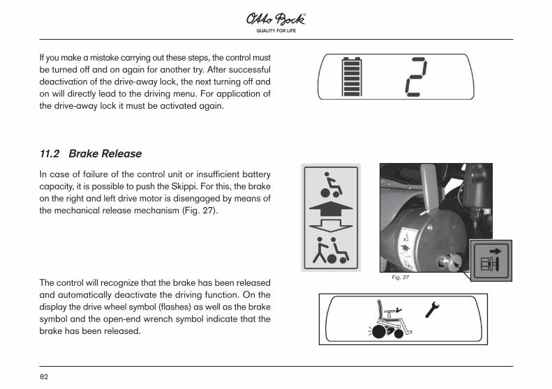
11.2 Brake Release
In case of failure of the control unit or insufficient battery capacity, it is possible to push the Skippi. For this, the brake on the right and left drive motor is disengaged by means of the mechanical release mechanism (Fig. 27).
The control will recognize that the brake has been released and automatically deactivate the driving function. On the display the drive wheel symbol (flashes) as well as the brake symbol and the open-end wrench symbol indicate that the brake has been released.
Fig. 27

83
Note!After turning the brake release lever into the pushing position, all brake systems are deactivated.Once the two brake levers are engaged again, the control releases the driving function.
11.3 Batteries
The Skippi comes factory-equipped with two maintenance-free 12 V, 31 Ah C20 gel batteries. The applied gel technology fulfils the latest provisions regarding safety and environmental tolerance through close construction. For increased safety and to facilitate handling, the batteries are integrated in separate battery packs. Thanks to special gel additions, these batteries are particular well-suited for electric drive systems and have been designed with a high cycle solidity. For exchange or disposal of the batteries (batteries within plastic pack), please contact your authorized dealer. The batteries are to be replaced as complete units. The housing must not be opened. Lead batteries are valuable substances. The batteries can be recycled to 100 % (Fig. 28).
Fig. 28

84
Fig. 29
Caution!Regularly checking of the remaining battery capacity and charging of the battery early enough are indispensable preconditions for the operational safety of your power wheelchair for children.
Caution!The Otto Bock warranty does not cover damages resulting from total discharge!
11.4 Fuse
The two 60 A fuses are located at the rear end of the battery packs between the battery’s bunch contacts (Fig. 29).
85
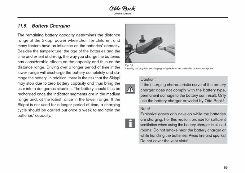
11.5. Battery Charging
The remaining battery capacity determines the distance range of the Skippi power wheelchair for children, and many factors have an influence on the batteries’ capacity. Besides the temperature, the age of the batteries and the time and extent of driving, the way you charge the batteries has considerable effects on the capacity and thus on the distance range. Driving over a longer period of time in the lower range will discharge the battery completely and da-mage the battery. In addition, there is the risk that the Skippi may stop due to zero battery capacity and thus bring the user into a dangerous situation. The battery should thus be recharged once the indicator segments are in the medium range and, at the latest, once in the lower range. If the Skippi is not used for a longer period of time, a charging cycle should be carried out once a week to maintain the batteries’ capacity.
Fig. 30Inserting the plug into the charging receptacle on the underside of the control panel
Caution!If the charging characteristic curve of the battery charger does not comply with the battery type, permanent damage to the battery can result. Only use the battery charger provided by Otto Bock!
Note!Explosive gases can develop while the batteries are charging. For this reason, provide for sufficient ventilation when using the battery charger in closed rooms. Do not smoke near the battery charger or while handling the batteries! Avoid fire and sparks! Do not cover the vent slots!

86
Battery Charger
1 Mains cable2 Battery cable3 Error indicator4 Charging indicator 15 Charging indicator 26 ON/OFF indicator
11.5.1 Charging Process
First connect the charging plug to the wheelchair control. Next, connect the mains plug to the mains supply. The mains plug functions as main switch, which means that the charging process automatically starts once connected to the mains supply.
Note!During battery charging, the control must be switched off to allow the complete charging current to be fed into the battery.
1
23 4 5 6

87
The current state of the charging process is indicated by the LEDs of the battery charger:
ON LEDCharging
indicator 1
Charging
indicator 2Error LED Function
On On Off Off Charge < 80%On Off On Off Charge > 80%On On On Off Charge 100%On Off Off Off Error 1On Off Off On Error 2Off Off Off Off Error 3
The battery charger features a programmed recharging phase. Once the battery is completely charged, the battery charger can remain connected with no risk of overcharging or damaging the battery. When the charging process is complete, first disconnect the battery charger from the mains supply and then from the control panel.
After removal of the battery charger the drive stop is no longer active and the Skippi is ready for driving.
Troubleshooting
Error Cause Solution1.Battery connection is missing
The battery is unconnected, the battery terminals/ plug is/are dirty, or the connection to the battery cables is interrupted.
Check the plug, cable and pos-sibly the fuse of the batteries.
2. General function fault
Wrong pole con-nection of the battery, battery charger fault and/or battery fault.
Contact your au-thorized dealer.
3. Supply line fault
There is no input voltage on the bat-tery charger.
Check the supply line and wall so-cket.
If you do no manage to eliminate the faults with the measures mentioned above, please contact your authorized dealer.

88
12 Status and Error IndicationThe following tables explain the different status and error messages on the display.
Display symbol(s) Information
Driving menu with speed level and battery capacity
Low battery capacity
Charging process with dri-ve stop
Electric back adjustment
Electric seat tilt
Coupled electric backrest and seat tilt adjustment
Note!Ensure that the vent slots on the charger are not covered. The battery charger should be used (darf nur) only within the indicated temperature and humidity ranges (see Sek.tion Technical Data – Battery Charger).
Make sure that the rubber feet of the battery charger stand on level ground. When the battery charger is in use, it must be protected from direct sunlight, since this would additionally heat up the charger. Avoid dust and dirt from affecting the function of the battery charger. To clean the charger, use a dry piece of cloth.

89
Display symbol(s) Information
Drive-away lock
Creep speed
Control for attendant
Display symbol(s)
Error/warning Cause
Control unit tem-perature warning
Overheating due to excessive load >> cooling down phase
Motor temperatu-re warning
Overheating due to excessive load >> cooling down phase
Joystick warning Joystick not in zero position when switching on
Hand control de-vice fault
Defective joystick

90
Display symbol(s)
Error/warning Cause
Control unit fault Defective control unit
Communication error (flash alter-nately)
Faulty connection between hand control device and control unit/ defective cabling, software or hard-ware
Battery: undervol-tage
Battery totally di-scharged/ charge as soon as pos-sible
Battery: overvol-tage
Voltage too high (after completed charging process and downhill drive)
Display symbol(s)
Error/warning Cause
Seat tilt motor fault
Faulty cabling / plug contactDefective actu-ator
Back adjustment motor fault
Faulty cabling / plug contactDefective actu-ator
Drive motor fault Faulty cabling / plug contactDefective motor
Brake fault Brake release open / defective brake

91
Display symbol(s)
Error/warning Cause
Emergency stop Severe fault caused by mal-function in the control unit, hand control device and/or drive motor

92
13 Options
The Skippi has been designed as a modular system. For accessories and options please refer to the order form. The options and adjustment possibilities are described in the following.
13.1 Control for Attendant
The control for attendant is a compact joystick module with On/Off button, mode button as well as battery and mode LED. The module can be connected to the control unit in combination with the hand control device or as single input device. Besides the driving function, the electric back adjus-tment and electric seat tilt can also be controlled.
1 ON/Off button2 Battery LED3 Seat functions4 Mode LED5 Mode button6 Joystick
1
2 3 4
5
6

93
13.1.1 On/Off Button
The On/Off button is located above the joystick on the left. The button is used for switching the power wheelchair on, for activating the drive-away lock and for switching the wheelchair off.
13.1.2 Battery LED
When turned on, the battery LED is lit. Three colors and flashing codes inform the user on the remaining battery capacity:
LED Status
Green is lit Capacity > 70%Orange is lit Capacity 30%...70%Red is lit Capacity < 30%
Red flashesBattery is discharged / charging is urgently re-quired
Green flashes Battery: overvoltageRed/orange/green flash alternately
Charging process / drive stop

94
13.1.3 Mode Button
Pressing the mode button (located above the display on the right) shortly, changes the speed level. Pressing the button for longer than 2 Sek.onds switches the control to the “Elec-tric seat functions” menu. For more information see Sek.tion “Electric Seat Functions – Control for Attendant”.
13.1.4 Mode LED
With three colors and different flashing codes, the mode LED indicates the status of speed level and system errors.
LED Status
Green is lit Speed level 1Orange is lit Speed level 2
Red flashes Error (see Sek.tion „Error Indication“)
Off Electric seat function

95
13.1.5 Electric Seat Functions – Control for Attendant
The control for attendant can also be used for controlling the electric seat functions. For this purpose, press the mode button, as already explained, for longer than 2 Sek.onds. The mode LED goes out and the seat function indicator is active. When the backrest LED is lit, the backrest can be electrically moved forward by deflecting the joystick forward. Deflect the joystick to the rear to move the back to the rear. The electric motor is active as long as the joystick is deflec-ted. The motor stops once the front or rear end position has been reached. Deflecting the joystick to the right switches the display from the backrest to the seat bottom.
To tilt the seat deflect the joystick backward. To bring the seat bottom back to horizontal position, deflect the joystick forward. Deflecting the joystick once again to the right leads to the coupled seat adjustment: The backrest and seat bottom are moved together forward and downward (into horizontal position) respectively or backward and upward (tilted position). Deflecting the joystick to the left brings you back to the driving menu.

96
13.1.6 Status/Error Indication – Electric Seat Functions
LED Status / Error
Backrest is lit Electric back adjustment is active
Seat bottom is lit Electric seat tilt is activeBackrest flashes Fault of electric back ad-
justmentSeat bottom flashes Fault of electric seat tiltBackrest and seat bottom flash
Electric seat function tem-perature warning
13.1.7 Switch-over Function – Control for Attendant/Hand Control Device
Both control devices can be used to turn on the Skippi po-wer wheelchair for children. If the Skippi has been turned on with the hand control device, you can switch the control function to the control for attendant by pressing the On/Off button of the control for attendant. The display of the hand control device then shows an A for Attendant Control and the battery capacity.
97
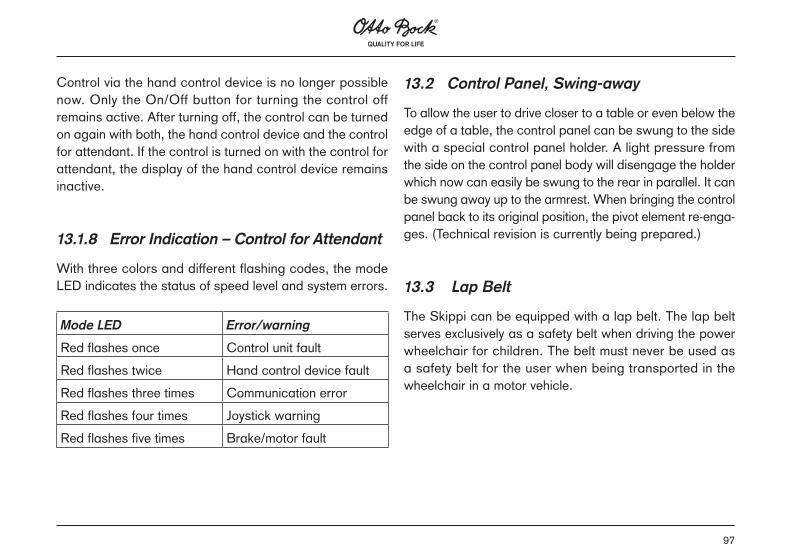
Control via the hand control device is no longer possible now. Only the On/Off button for turning the control off remains active. After turning off, the control can be turned on again with both, the hand control device and the control for attendant. If the control is turned on with the control for attendant, the display of the hand control device remains inactive.
13.1.8 Error Indication – Control for Attendant
With three colors and different flashing codes, the mode LED indicates the status of speed level and system errors.
Mode LED Error/warning
Red flashes once Control unit faultRed flashes twice Hand control device faultRed flashes three times Communication errorRed flashes four times Joystick warningRed flashes five times Brake/motor fault
13.2 Control Panel, Swing-away
To allow the user to drive closer to a table or even below the edge of a table, the control panel can be swung to the side with a special control panel holder. A light pressure from the side on the control panel body will disengage the holder which now can easily be swung to the rear in parallel. It can be swung away up to the armrest. When bringing the control panel back to its original position, the pivot element re-enga-ges. (Technical revision is currently being prepared.)
13.3 Lap Belt
The Skippi can be equipped with a lap belt. The lap belt serves exclusively as a safety belt when driving the power wheelchair for children. The belt must never be used as a safety belt for the user when being transported in the wheelchair in a motor vehicle.

98
13.4 Seat Options
13.4.1 Electric Seat Tilt
An electric seat tilt adjustment is optionally available for the Skippi. It allows quick change of the seat position from 0° to 25° in order to achieve pressure relief. The electric seat tilt is controlled via the control panel (mode button) (Fig. 31).
13.4.2 Mechanical Seat Tilt
A mechanic seat tilt adjustment is also available for the Skip-pi. This seat tilt adjustment by means of a gas compression spring is operated with a release lever at the push handles. Angle adjustment here also ranges from 0° to 25°.
13.4.3 Electric Back Angle Adjustment
The electric back angle adjustment allows for continuous adjustment from 81° to 121° or from 90° to 120°. The electric back angle adjustment is controlled via the control panel (mode button) (Fig. 32).
Fig. 31 Fig. 32
Gefahr!Überlastung der Aktuatoren kann zum Bruch der Spindelmutter und somit zum Absacken des Sitzes, bzw. zum Zurückklappen des Rückens führen.
Hinweis!Die Aktuatoren sind nicht für Dauerbetrieb, sondern für eine 10%ige Belastung ausgelegt. Bei einer Betriebsdauer von 1h kann also die Aktuatoren-funktion max. 6 Minuten lang betätigt werden.

99
13.5 Other Options
1. Joystick accessories • Fork for tetraplegics • STICK S80 • Soft ball • Golf ball 2. Headrest mounting kit Headrests of our Accessories Catalog 3. Protective bow for control panel Metal bow for protecting the control panel against shocks and damage 4. Bumper bar (Fig. 33) 5. Manual horn (Fig. 34) 6. Pennant (Fig. 35) 7. Tray 8. Mid-tray control (Fig. 36) 9. Control for attendant (Fig. 37)10. Lighting
These and other optional add-on components are described on the order form and in the Accessories Catalog.
(Abb) D2_3609 (Abb) D2_3624
Fig. 33
Fig. 35
Fig. 34
Fig. 36
Fig. 37
100
14 Maintenance, Cleaning and Care
14.1 Maintenance
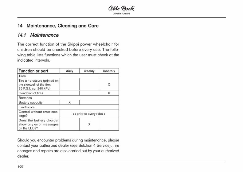
The correct function of the Skippi power wheelchair for children should be checked before every use. The follo-wing table lists functions which the user must check at the indicated intervals.
Should you encounter problems during maintenance, please contact your authorized dealer (see Sek.tion 4 Service). Tire changes and repairs are also carried out by your authorized dealer.
Function or part daily weekly monthly
TiresTire air pressure (printed on the sidewall of the tire: 35 P.S.I. ca. 240 kPa)
X
Condition of tires XBatteriesBattery capacity XElectronicsControl without error mes-sage? >>prior to every ride>>
Does the battery charger show any error messages on the LEDs?
X

101
14.2 Care
When cleaning the Skippi with water, please be particularly careful with the electrical components. Please observe the following instructions:
• For cleaning the control panel, battery charger and arm-rest use only a damp piece of cloth and a mild cleansing solution.
• For cleaning the back upholstery and seat cushion use a dry brush.
• For cleaning wheels and frame use a damp plastic brush.
• Please prevent the electronics, motors and batteries from direct contact with water.
• Do not use any scouring agents.• Never use a water hose or high-pressure cleaning ap-
paratus for cleaning the wheelchair.
Note!Please ensure that your Skippi power wheelchair for children is checked and serviced at least ONCE a year by an authorized dealer!
14.3 Cleaning and Disinfection
Clean the padding and upholstery with warm water and a washing-up liquid. Remove spots with a sponge or a soft brush. Rinse with clear water and let the components dry.
Note!Do not use any aggressive cleansing agents, solvents, or hard brushes etc.
Note!No wet-cleaning. No machine-wash.
For disinfection, agents on water basis (e.g. Sagrothan original concentrate) should be used. The manufacturer’s instructions for use must be observed.
Note!Before disinfecting, the pads and handles must be cleaned.
Plastic parts, frame parts as well as chassis and wheels can be cleaned with a mild detergent. Dry thoroughly.

102
15 Disposal
Normally, the Skippi power wheelchair for children is the property of the health insurance company. Therefore, it is returned to the health insurance company after use.If the wheelchair is privately owned, the following disposal instructions apply:Please return defective batteries to your dealer when buying new ones.If the Skippi power wheelchair for children is no longer in use, please give the batteries to a corresponding recycling office. The same applies to wheels, frame, and seat. The electronic components and motors will be disposed of by the division of your local waste disposal organization which is responsible for electronic scrap.These guidelines for disposal apply to the manufacturing country of the Skippi. For use and disposal of the wheelchair in other countries, the disposal regulations of the respective country shall apply.

103
16 Technical Data – Skippi
Measurements and weights
Seat width: 26 - 38 cmSeat depth: 30 - 37 cmSeat height: 43 cmArmrest height: 16 - 27 cmArmrest length: 23 cmLower leg length: 11 - 18 cm or 19 - 26 cmBack height: 35/40/42/44/46 cmBack angle: -9/1/11/21° (at 3° seat angle) or 0/10/20/30°optional electrical: 0° to 25°Seat angle: -6°/3°/12°optional continuously adjustable: 3° to 28°Overall width: 57 cmOverall height: 103 cmOverall length with legrests: 85 cmOverall length without legrests: 70 cmTurning radius: 52 cmTire size, front: 8’’rear: 12.1/2x2.1/4’’Tire air pressure 240 kPa
(printed on the sidewall of the tire)Weight when empty: 62 kgMaximum load capacity: 50 kg Electrical Installation
Control unit: EnAble 40 with control unit and hand control deviceOperating voltage: 24 V DCMax. output current per motor 50ABatteries: Gel batteries: 2 x 12 V, 31 Ah C20Battery charger model: Powercharge Standard 5AFuse: 60 A in each battery packDriving DataSpeed: 6 km/hClimbing ability: 12 %Obstacle height that can be cleared: 50 mmDistance range: approx. 25 km
104
17 Technical Data – Battery Charger
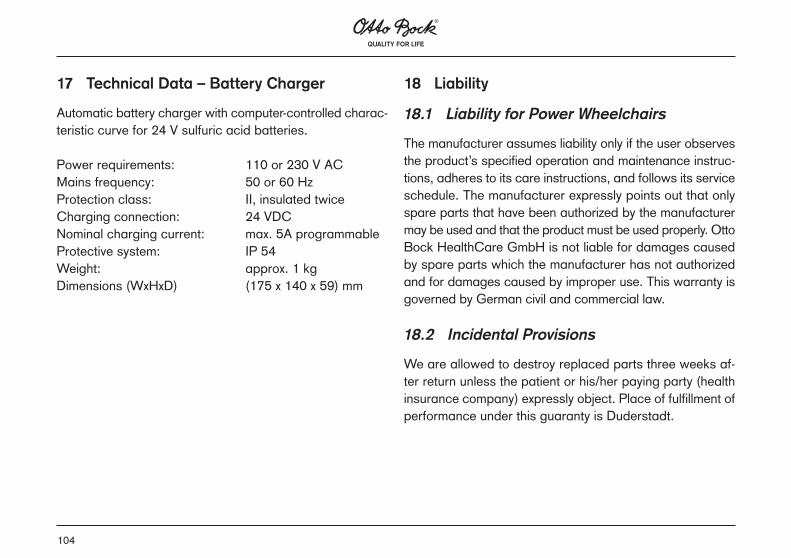
Automatic battery charger with computer-controlled charac-teristic curve for 24 V sulfuric acid batteries.
Power requirements: 110 or 230 V ACMains frequency: 50 or 60 HzProtection class: II, insulated twiceCharging connection: 24 VDCNominal charging current: max. 5A programmableProtective system: IP 54Weight: approx. 1 kgDimensions (WxHxD) (175 x 140 x 59) mm
18 Liability
18.1 Liability for Power Wheelchairs
The manufacturer assumes liability only if the user observes the product’s specified operation and maintenance instruc-tions, adheres to its care instructions, and follows its service schedule. The manufacturer expressly points out that only spare parts that have been authorized by the manufacturer may be used and that the product must be used properly. Otto Bock HealthCare GmbH is not liable for damages caused by spare parts which the manufacturer has not authorized and for damages caused by improper use. This warranty is governed by German civil and commercial law.
18.2 Incidental Provisions
We are allowed to destroy replaced parts three weeks af-ter return unless the patient or his/her paying party (health insurance company) expressly object. Place of fulfillment of performance under this guaranty is Duderstadt.

105
19 Information regarding Re-Use
The Skippi power wheelchair for children is suitable for re-use. For this purpose, the product must at first be cleaned and disinfected thoroughly. Afterwards, the product must be examined by an authorized dealer for proper condition, wear and tear, and damages. Any worn and damaged components as well as components which do not fit or are unsuitable for the new user must be replaced. The Service Manual includes a service plan for each model, detailed information and a list of the required tools.