Embed Size (px)
DESCRIPTION
Coal Bed Methane Operations
Citation preview
®
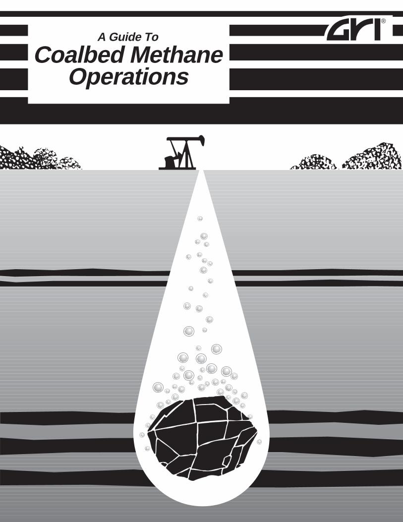
A Guide To
Coalbed MethaneOperations
A Guide toCoalbed Methane
Operations
v v v
Copyright © 1992 by Gas Research InstituteAll Rights Reserved
By
Vicki A. HollubTaurus Exploration, Inc. (Birmingham, Alabama)
Paul S. SchaferSchafer Associates (Oxford, Ohio)
1
ge ofring
alenrvoirte
About the Authors
LEGAL NOTICE: This publication was prepared as an account of work sponsored byGas Research Institute (GRI) and other organizations. Neither GRI, members of GRI, norany person acting on behalf of either:
a. makes any warranty or representation, express or implied, with respect to theaccuracy, completeness, or usefulness of the information contained in this publication, northat the use of any information, apparatus, method, or process disclosed in this publicationmay not infringe privately owned rights; or
b. assumes any liability with respect to the use of, or for damages resulting fromthe use of, any information, apparatus, method, or process disclosed in this publication.
Reference to trade names or specific commercial products, commodities, or services in thispublication does not represent or constitute an endorsement, recommendation, or favoringby GRI of the specific commercial product, commodity, or service.
Disclaimer
Vicki A. Hollu b, P.E. works with Taurus Exploration, Inc. as a reservoir engineer at the GRI RockCreek research project in Alabama. She previously worked ten years with OXY USA as a drillinengineer and as a senior production engineer. Vicki holds a B.S. in Mineral Engineering from ThUniversity of Alabama and is a registered professional engineer. She is a member of the SocietyPetroleum Engineers (SPE) and currently serves as chairperson of the SPE Professional EngineeRegistration Committee.
Paul S. Schafer owns and operates Schafer Associates, a consultancy that provides techniccommunication services to the petroleum and petrochemical industries. He previously worked tyears with Marathon Oil Company as a production and operations engineer and as an advanced reseengineer. Paul holds a Master of Technical and Scientific Communication from Miami University aOxford, Ohio and a B. S. in Petroleum Engineering from Marietta College. He is a member of thSociety of Petroleum Engineers and the Society for Technical Communication.
❖ ❖ ❖
1A
About This Guide
AGuide to Coalbed Methane Operations provides practicalinformation on siting, drilling, completing, and producing coalbedmethane wells. Whether you’re an experienced coalbed methaneproducer or you’re exploring coalbed methane operations for the firsttime, this guide will give you the information you need to makeinformed decisions about producing this resource.
This guide is a “working reference.” It will help you inplanning and performing field activities. Each chapterprovides an overview of key field operations as well asspecific guidelines for performing them. The chapters alsodescribe the equipment and materials required for eachoperation. Though the guide focuses on developing mul-tiple coal seams in the Black Warrior Basin, you can applymany of the concepts to other coal basins as well.
You will notice an emphasis on practical applications ratherthan lengthy technical explanations and engineering data.However, if you want to investigate any of the topics ingreater depth, the Additional Resources section at the endof each chapter will guide you to selected references.
The information in this guide represents the shared knowl-edge and expertise of many specialists in the coalbedmethane field. Much of this information resulted fromGRI’s Rock Creek Methane from Multiple Coal SeamsCompletion Project and from several operators and servicecompany representatives in the Black Warrior Basin ofAlabama. We hope this guide contributes to greater un-derstanding of coalbed methane production and moreeconomical development of this gas resource.
❖ ❖ ❖
i
Table of Contents
About this Guide iList of Figures and Tables ivConventions Used in This Guide viiAcknowledgments viiiAbout Producing Coalbed Methane x
Chapter I Selecting and Preparing a Field Site 1-1Protecting Wetland Areas 1-2Disposing Produced Water 1-3Controlling Non-Point Source (NPS) Pollution 1-4Preventing Spills 1-13Safety and Operating Guidelines 1-14
Chapter 2 Drilling and Casing the Wellbore 2-1Planning the Drilling Program 2-2Drilling the Wellbore 2-32Coring the Wellbore 2-36Casing and Cementing the Wellbore 2-4
Chapter 3 Wireline Logging 3-1Sources for Estimating Reservoir Properties 3-2Open Hole Logging Tools 3-4Selecting an Open Hole Logging Suite 3-35Guidelines for Open Hole Logging 3-36Cased Hole Logging Tools 3-37Selecting a Cased Hole Logging Suite 3-41Guidelines for Cased Hole Logging 3-42Production Logging Tools 3-44
Chapter 4 Completing the Well 4-1Reservoir Considerations in Completing Coalbed Methane Wells 4-2Objectives of Completing the Well 4-2Completing in Open Hole 4-4Completing in Cased Hole 4-8Accessing the Formation 4-10Selecting Production Tubing 4-27Working Over Wells 4-27
ii
Chapter 5 Fracturing Coal Seams 5-1Performing a Minifracture Test 5-2Planning a Fracture Treatment Design 5-4Preparing for a Fracture Treatment 5-30Performing a Fracture Treatment 5-35Evaluating a Fracture Treatment 5-48
Chapter 6 Selecting Production Equipment and Facilities 6-1Estimating the Volume of Water to be Produced 6-2Pumping Equipment 6-3Power Supply for Pumping Equipment 6-19Surface Production Facilities 6-23Gas Compressors 6-35Gas Dehydration Equipment 6-40
Chapter 7 Operating Wells and Production Equipment 7-1Preparing Surface Facilities for Production 7-2Unloading the Well 7-3Bringing the Well on Line 7-8Troubleshooting Well and Equipment Problems 7-8
Chapter 8 Treating and Disposing Produced Water 8-1Characteristics of Coalbed Methane Produced Water 8-2Regulations and Permitting for Water Disposal 8-6Considerations for Designing a Water Disposal System 8-8Methods for Treating and Disposing Produced Water 8-10
Chapter 9 Testing the Well 9-1Performing Pressure Transient Tests 9-2Evaluating Production from Multiple-Seam Wells 9-21
Appendix A Summary of Permitting Requirements for Drilling a CoalbedMethane Well in Alabama
Appendix B Quality Control and Job Supervision Guidelines for StimulationTreatments
Appendix C Procedures and Surface Equipment for Implementing the ForcedClosure Fracturing Technique
❖ ❖ ❖
iii
Chapter 4 Completing the WellFigure 4-1 Single-Zone Open Hole Completion 4-5
Figure 4-2 Multiple-Zone Open Hole Completion 4-8
Figure 4-3 Multiple-Zone Cased Hole Completion 4-9
T
Chapter 2 Drilling and Casing the WellboreFigure 2-1 The Planning Process for Drilling a Coalbed Methane Well 2-2
Figure 2-2 Setting Casing Through Zones with Lower Fracture Gradients 2-5
Figure 2-3 Selecting Hole Size 2-7
Figure 2-4 Casing Selection Chart 2-11
Figure 2-5 Conventional Rotary and Rotary-Percussion Drilling Techniques 2-16
Figure 2-6 Typical Cementing Manifold 2-50
Figure 2-7 Two Stage Cementing 2-52
Figure 3-1 Bulk Density Log 3-6
Figure 3-2 Comparison of Conventional and Mineral Logging Density Logs 3-9
Figure 3-3 Dual Induction/Shallow Log 3-13
Figure 3-4 Phasor Induction Log 3-14
Figure 3-5 SP Log 3-20
Figure 3-6 Compensated Neutron Log 3-21
Figure 3-7 Comparison of Cleat Orientation from Microscanner® Log & Cores 3-23Figure 3-8 Sonic Log 3-25
Figure 3-9 Full Waveform Sonic Log 3-27
Figure 3-10 Geochemical and Carbon/Oxygen Log 3-29
Figure 3-11 VOLAN® Log 3-30
Figure 3-12 Spectral Gamma Ray Log 3-32
Figure 3-13 Computer-Processed Coal Quality Log 3-34
Figure 3-14 Cement Bond/Variable Density Log 3-40
Figure 3-15 Wellhead Configuration for Annular Logging 3-44
Figure 3-16 Flowmeter Developed for Coalbed Methane Wells 3-46
Figure 3-17 Flowmeter Log 3-47
Figures and Tables
Chapter 3 Wireline Logging
Table 3-1 Primary Non-Log Sources for Estimating Reservoir Properties 3-2
Table 3-2 Logging Sources for Estimating Reservoir Properties 3-3
Table 3-3 Matrix Densities for Common Formations 3-7
Table 3-4 Photoelectric Absorption Index for Common Formations 3-10
Table 3-5 Total Natural Radioactivity of Common Formations 3-11
Table 3-6 Responses for Logs Commonly Used to Evaluate Coals 3-16
Table 3-7 Logging Tools for Open Hole Exploration Wells 3-35
Table 3-8 Logging Tools for Open Hole Development Wells 3-36
Table 3-9 Logging Tools for Cased Hole Wells 3-42
2 - 1
3 - 1
4 - 1
i v
Figure 6-1 Beam Pumping System 6-5
Figure 6-2 Top-Seating Pump Hold-Down 6-8
Figure 6-3 Bottom-Seating Pump Hold-Down 6-9
Figure 6-4 Gas Anchor 6-10
Figure 6-5 Progressing Cavity Pump 6-13
Figure 6-6 Gas Lift Installation 6-16
Figure 6-7 Electric Submersible Pump 6-18
Figure 6-8 Water Flow Path for Fields In Black Warrior Basin 6-24
Figure 6-9 Gas Flow Path for Fields In Black Warrior Basin 6-30
Figure 5-1 Instantaneous Shut in Pressure (ISIP) 5-8
Figure 5-2 Wellbore Configurations for Fracturing 5-13
Figure 5-3 "Dead String" for Measuring Bottomhole Pressure 5-16
Figure 5-4 Nolte Plot for Evaluating Fracture Pressures 5-38
Figure 5-5 Tiltmeter Sensor 5-53
Figure 5-6 Tiltmeter Installation 5-54
Figure 5-7 Tiltmeter Displays for Fractures 5-55
Figure 4-7 Limited Entry Multiple-Zone Completion 4-22
Figure 4-8 Lithology of the Well P5 Interseam Completion 4-25
Figure 4-4 Perforated Cased Hole Completion 4-12
Figure 4-5 Slotted Cased Hole Completion 4-13
Figure 4-6 Fracture Communication from Restricted Access 4-21
Table 5-1 Minifracture Tests 5-2
Table 5-2 Information for Designing a Fracture Treatment 5-5
Table 5-3 Pumping Schedule for a Gel Fracture Treatment 5-28
Table 5-4 Pumping Schedule for a Foam Fracture Treatment 5-29
Table 6-1 Artificial Lift Methods for Coalbed Methane 6-4
Table 6-2 Comparison of Gas Flow Meters 6-32
Table 6-3 Typical Sales Gas Specifications 6-33
Figure 8-1 Water Disposal System in Black Warrior Basin 8-13
Chapter 5 Fracturing Coal Seams
Chapter 8 Treating and Disposing Produced Water
Chapter 7 Operating Wells and Production Equipment
Chapter 6 Selecting Production Equipment and Facilities
8 - 1
7 - 1
6 - 1
5 - 1
Figure 7-1 Beam Pumping System 7-10
Figure 7-2 Troubleshooting Beam Pumps (I) 7-11
Figure 7-3 Troubleshooting Beam Pumps (II) 7-12
Figure 7-4 Troubleshooting Progressing Cavity Pumps 7-16
Table 8-1 Typical NPDES Water Discharge Limitations 8-7
v

Figures and Tables (Cont'd)
Figure 9-1 Slug Test Equipment Configuration 9-4
Figure 9-2 Typical Coalbed Methane Production Decline Curve 9-23
Figure 9-3 Two-Seam Well Test Using the ZIP Tool 9-24
Figure 9-4 Three-Seam Well Test Using the ZIP Tool 9-25
Table 9-1 Data Frequency for Slug Tests 9-8
Chapter 9 Testing the Well
❖ ❖ ❖
9 - 1
v i
Conventions Used inThis Guide
everal special elements in this guide’s text will help you quicklyidentify different types of information:
4. Numbered information gives step-by-step instructions for a procedure.
n A solid box indicates general guidelines to follow before orduring a particular task.
v A cut diamond highlights a list of characteristics, features,benefits, or limitations of an object, technique, or procedure.
u A solid diamond describes a circumstance or condition youmight encounter and then explains possible ways to respond tothe situation.
▲ CautionA triangular “caution” note wa rns you about a situation that couldbe unsafe, environmentally hazardous, or damaging to equipment.
❈ImportantInformation that is particularly important for you to understand ishighlighted with the symbol above.
S
vii
A
v i i i
1
Acknowledgments
A Guide to Coalbed Methane Operations was possible because of thegenerous contributions of experience and knowledge by the people listedbelow:
Dr. Richard Schraufnagel — Gas Research Institute (GRI)Senior Project Manager, Coalbed Methane EngineeringDr. Schraufnagel generated the concept for this guide andprovided important guidance and support throughout its develop-ment.
Stephen Spafford — Taurus Exploration, Inc.Manager, Rock Creek ProjectSelecting and preparing a field site, drilling, completing, fractur-ing, and treating and disposing produced water
Francis Dobscha — GeoMet, Inc.Special thanks to Fran for his extensive contributions on selectingand preparing a field site, drilling, completing, fracturing, select-ing production equipment, operating wells and production equip-ment, treating and disposing produced water, and testing wells
Jerry Saulsberry — Taurus Exploration, Inc.Drilling, wireline logging, fracturing, and testing wells
Peter Steidl — Taurus Exploration, Inc.Wireline logging
Paul Stubbs — GeoMet, Inc.Testing wells
Randy McDaniel — Taurus Exploration, Inc.Selecting and preparing a field site, and treating and disposingproduced water
Brian Luckianow — Taurus Exploration, Inc.Selecting and preparing a field site, and treating and disposingproduced water
Jerry Sanders and Eddie Jones — Black Warrior Methane, Inc.Drilling, fracturing, selecting production equipment and facili-ties, and operating wells and production equipment
Michael Conway — Stim-Lab, Inc.Completing and Fracturing
Allen Neel and Bill Lawrence — Black Warrior Drilling andCompletion Company
Drilling and completing
Brad Taff and Ted Martin — Halliburton Logging Services, Inc.Wireline logging
Daniel Felcman and Doug Womack — Tidewater CompressionServices, Inc.
Selecting gas compression equipment
Brad Benge and Roger Hudson — Tidewater CompressionServices, Inc.
Operating and maintaining gas compression equipment
Richard Montman, Dick Bretzke, and Robert Singleton — HalliburtonServices, Inc.
Fracturing and cementing
Jerry Broadway — Black Warrior Drilling and Completion Com-pany
Selecting and operating progressing cavity pumps
Adam Olszewski — ResTech, Inc.Wireline logging
Larry Strider — AMPCO Resources, Inc.Drilling, completing, and selecting pumps
Gary Conner — Computalog Wireline Services, Inc.Production logging
David Stuart — Robbins and Myers, Inc.Selecting and operating progressing cavity pumps
Matt Hollub — Graphic ArtistCover Art
❖ ❖ ❖
i x
About ProducingCoalbedMethane
oalbed methane is produced commercially in the United States, and ithas attracted worldwide attention as a potential source of costcompetitive natural gas. Since the beginning of the coalbed methane industry in the mid1970s,operators havemodified and applied petroleum industry technology toimprove the operation of their fields. However, conventional oil and gas tech-nology does not always work effectively for producing coalbed methane.Because coal geology is so different from that of typical gas formations, youmust use a different approach that takes into account:
■ The composition of the rock. Coal is 90 percent organic, whereas conventional gas formations are nearly 100 percent inorganic.
■ The different mechanical properties of coal. Coal is brittle andweak, and it tends to collapse in the wellbore.
■ Coal’s naturally occurring fractures, or cleats. These fractures,called face cleats and butt cleats, are extensive in coals. Most coalreservoirs, however, require hydraulic fracturing to stimulate production.
■ Coal’s gas storage mechanism. Gas is adsorbed or attached onto theinternal surfaces of the coal, whereas gas is confined in the pore spacesof conventional rocks.
■ The large volumes of water present in the coal seams. Water must bepumped continuously from coal seams to reduce reservoir pressureand release the gas.
■ The low pressure of coal reservoirs. Backpressure on the wellheadmust be kept low to maximize gas flow. And all produced gas must becompressed for delivery to a sales pipeline.
■ The modest gasflow rates from coal reservoirs. Capital outlays andoperating expenses must be minimized to produce an economicalproject.
C
x
xi
These unique characteristics of coalbed reservoirs will allow few ineffi-ciencies. Successfully developing a coalbed methane field requires prudently managing the technical as well as the economic aspects of the project.
To develop techniques for economically producing coalbed methane fields,Gas Research Institute (GRI) and Taurus Exploration, Inc. designed TheRock Creek Methane from Multiple Coal Seams Completion Project. Thisfield research site is located in the Black Warrior Basin southwest of Birmingham, Alabama.
The overall objective of this project, initiated in 1983, is to develop technology for more cost-effective production of methane from shallow, thinmultiple coal seams using single vertical wellbores. Ile project has specifically focused on determining the best combination of drilling, completing,stimulating, and operating techniques to economically produce these wells.
The Rock Creek project and the work of other operators in the Black War-rior Basin have produced many practical techniques and guidelines fordeveloping coalbed methane fields. The cooperation and open communi-cation between operators and service companies in the Black WarriorBasin have been necessary to advance both basic knowledge and appliedexperience in producing methane from coal seams.
❖ ❖ ❖
C
t
e
hapter
1 Selecting and Preparing a Field Site
As citizens become increasingly aware of and concerned about envi-ronmental issues, the number and scope of environmental regulationscontinue to grow. Certain activities related to coalbed methaneproduction are regulated by State and Federal agencies to help prevendamage to the environment. By incorporating sound environmentalmanagement into the planning and operation of a coalbed methanefield, you will help protect the environment, minimize current regula-tory requirements, and possibly avoid costly penalties.
You should become familiar with the applicable environmental regu-lations in your area before selecting and preparing a field site. The U.S.Environmental Protection Agency (EPA) has primary jurisdictionover environmental regulations in the United States, but administra-tion of regulations varies from state to state. In the Black WarriorBasin of Alabama, the Alabama Department of Environmental Man-agement (ADEM) and the Army Corps of Engineers (ACOE) admin-ister most environmental regulations.
Environmental Guidelines
I n selecting and preparing a field site, you will make some of themost important decisions about the coalbed methane project. Thesdecisions will affect the environmental, safety and operations aspectsof the project. These factors, in turn, will likely influence the project’seconomic success.
Chapter 1 Selecting and Preparing a Field Site
rys.inane
e
ste
sd
lde
s
alvefs
1-2
methane sites in the Black Warrior Basin are:
• Protecting Wetland Areas
• Disposing Produced Water
• Controlling Non-Point Source (NPS) Pollution
• Preventing Oil Spills
• Protecting Historical Sites
Protecting Wetland AreasThe impact of wetlands presents the single most critical regulatoissue in establishing right-of-way for pipelines, roads, and padOperating coalbed methane facilities often requires some activity wetlands (e.g. an access road or a pipeline system). Coalbed methfacilities or activities which occur in wetlands are regulated andrequire a permit.
By knowing wetlands regulations, you can incorporate them into sitplanning to avoid or minimize dirt fill placed in wetlands. If youconsider wetlands at the onset of planning, you can likely locate mofacilities in non-wetland (upland) areas and thus avoid or minimizregulatory permitting.
To identify or verify wetlands areas within the proposed site, youshould have a qualified biologist who knows the wetlands regulationconduct a field survey. Make sure this wetlands survey is conductebefore completing final field development plans.
Regulatory agencies use “The Federal Manual for Identifying andDelineating Wetlands” (“Federal Manual” ) as the technical basis foridentifying and delineating wetlands. The person conducting the fieinvestigation must be familiar with wetlands and must be trained to usthis manual.
Because the ACOE makes final decisions on jurisdictional wetlanddelineations, you should confirm the findings of the field survey withthe ACOE. If the area is determined to be a wetland, a jurisdictionwetland boundary should be delineated. If possible, you should mothe proposed facility site to avoid or minimize impacts to wetlands. Iyou cannot avoid impacts to wetlands, you must apply for a wetland
on to
i-elde
rdS
isr
-he
Disposing Produced Water
permit. For more information about permits, refer to AdditionalResources at the end of this chapter.
Disposing Produced WaterThe ability to dispose produced water is key to the successful operatiof a coalbed methane field. Produced water must be managedcomply with the National Pollutant Discharge Elimination System(NPDES) requirements. The NPDES is governed by the U.S. Envronmental Protection Agency (EPA) and is administered locally by thstates. If NPDES standards are not met, production from the fiecould be forced to stop. Therefore, you must carefully plan for thmanagement of produced water when selecting the field site.
The NPDES program defines the criteria for discharging wateproduced from coalbed methane wells into waterways. No producewater can be discharged into a river or stream without an NPDEpermit. In the Black Warrior Basin, this program is administered bythe Alabama Department of Environmental Management (ADEM).
Your selection of a field site should be based on a thorough analysof water treatment and disposal options (refer to Chapter Eight fomore information). Begin by learning the NPDES permitting requirements and procedures in your area. Give special attention to tquestions below, which could influence your choice of a site:
■■■■■ What is the maximum volume of produced water which I willneed to dispose?
■■■■■ What is the chemical composition of this water?
■■■■■ Are there waterways near the site that could be used for waterdischarge?
■■■■■ Do these waterways have sufficient year-round flow to allowdischarge in compliance with discharge limits?
■■■■■ Are other operators using the same drainage basin to dis-charge produced water?
1-3
Chapter 1 Selecting and Preparing a Field Site
1-4
■■■■■ What discharge limits do the regulatory agencies place onthe waterway overall and on individual dischargers into thewaterway?
■■■■■ What is the life of a discharge permit?
■■■■■ How do I renew a discharge permit?
For more information on treating and disposing of produced water,refer to Chapter Eight.
The Alabama Department of Environmental Management (ADEM)defines a pollutant as any item entering a waterbody that changes thecomposition of the water. A pollutant entering a waterbody througha NPDES permitted discharge is called a point source discharge.However, a pollutant that reaches a waterbody by other means that arenot traceable to an identifiable facility, such as storm water runoff,seepage, percolation, etc., is called a non-point source discharge.
Non-point source regulation, which is controlled in Alabama byADEM and EPA, probably receives the highest priority of anyregulation during coalbed methane development, and has increasedthe finding cost for methane significantly in recent years. Therefore,when planning a field site, you should consider the requirementsconcerning non-point source pollution.
One of the best ways to manage potential non-point source dischargeis by implementing a Best Management Practices Plan (BMP) A BMPpresents policies and procedures that can lessen the probability ofinitial causes of non-point source pollution. The Coalbed MethaneAssociation of Alabama developed such a plan to assist operators inthe Black Warrior Basin. This BMP, which is presented below,provides sound guidelines for:
• Controlling Erosion
• Siting and Constructing Roads
Controlling Non-Point Source (NPS) Pollution
ntsse
ng
,
d
Controlling Non-Point Source Pollution
• Developing Drilling Locations
• Siting and Constructing Pipelines
• Preventing Oil Spills
Controlling ErosionThe major component of non-point source pollution is sedimentatiofrom soil erosion. Sedimentation reduces stream capacities, interrupecosystems, carries other pollutants into a waterbody and may cauother potential environmental problems. Soil types, which varygreatly from one location to another, significantly influence soilerosion characteristics and are a factor in designing and implementiBMPs.
To minimize erosion when constructing coalbed methane facilitiespractice these general erosion control techniques:
■■■■■ Divert runoff from well sites and roads onto level vegetatedareas, terracing, riprap, or other areas that will disperse thewater and prevent soil erosion.
■■■■■ Install temporary erosion controls such as hay bales and/or siltfences in the natural drainage areas before or during theconstruction of well sites, roads, etc.
■■■■■ Install more permanent erosion control devices (i.e., geotextiles,riprap, matting, etc.) in areas of severe erosion.
■■■■■ Line, fertilize, and seed and/or mulch roadsides, drilling loca-tions and pipelines where slopes are sufficient to cause highvelocity flow and erosion.Perform this operation as soon as practical after construction anuse accepted soil conservation practices.
1-5
Chapter 1 Selecting and Preparing a Field Site
lt
s.e
d
t
1-6
■■■■■ Pave and cover with gravel or plant vegetation on all disturbedareas, regardless of location.Perform this operation as soon as practical, and maintain alerosion controls until the disturbed area is covered or permanenvegetation is re-established.
■■■■■ Reuse onsite topsoil, if available, on the surface of each site.This action will help maintain vegetation in disturbed areas.
Siting and Constructing RoadsRoads are necessary to provide access to each well and to facilitiePermanent access roads are usually built so that equipment can bmoved in and out of the locations as needed initially and during latermaintenance. Roads also provide access for monitoring wells anfacilities.
When siting access roads, follow the guidelines below to the extenpractical:
■■■■■ Use existing roads, when suitable, to prevent further soildisturbance.
■■■■■ Site roads along ridge lines to minimize road grades and tolessen the potential of disturbing a water course.
■■■■■ Minimize road grades whenever practical.
When constructing roads, follow the guidelines below wheneverpractical:
■■■■■ Construct roads and roadway drainage only under the guid-ance of a person experienced in road construction techniquesand erosion control.
■■■■■ Install velocity breakers (stabilized water bars) to control highvelocity flow and potential stream erosion.
rolze
n
yhe9tu-
s
r
-a-
nyuse
Controlling Non-Point Source Pollution
■■■■■ Avoid constructing roads through areas having highly erodiblesoils, wetlands or wet meadows.If necessary to build roads in these areas, use erosion contmethods and wetland road construction techniques to minimidisturbance.
If operations are not permitted under Section 404 of the CleaWater Act (Nationwide Permit) you must obtain individual permitsfrom the U.S. Corps of Engineers (ACOE) before disturbing anwetland area. In addition, you may need an ACOE permit under trequirements of Section 10 of the Rivers and Harbors Act of 189and/or section 193 of the Marine Protection, Research and Sancaries Act.
■■■■■ Test quarterly for pH any mine tailings (i.e., black or red rock)used in roadbed construction.Test each source of “black or red” rock.The pH must range from 6 to 9 pH units.Keep good records of the testing for three years.
■■■■■ Never use known hazardous or toxic materials in constructingroadbeds.
■■■■■ Maintain vegetated filter strips of sufficient length to assistsediment deposition between streams and roads.
If terrain limitations necessitate, use other permanent method(geotextiles, riprap, matting, etc.) instead of or in conjunction withvegetated filter strips, provided the water course is not altered odiverted.
■■■■■ Take measures to prevent construction materials (dirt, boul-ders, rock, trees, etc.) from being deposited into water-bodies.
If these materials inadvertently enter the water, take environmentally sound measures to remove them immediately. These mesures should prevent further environmental damage.
Constructing Stream CrossingsBecause of the topography of coalbed methane operations in maareas, you may need to cross a stream with a road. Roadways can ca
❈❈❈❈❈ Important
1-7
Chapter 1 Selecting and Preparing a Field Site
1-8
more water course disturbance, redirect flow, and/or possibly limitmovement of stream life. Through planning and careful construction,you can eliminate or significantly lessen potential environmentaldamage when crossing streams.
When developing roadstream crossings, follow the guidelines belowwhenever practical:
■■■■■ Minimize stream crossings whenever practical. Use existingculverts, bridges, fords and/or other crossings whenever pos-sible.
■■■■■ Make stream crossings at right angles to the main streamchannel, when practical and/or when it will limit environmen-tal damage.
■■■■■ Test quarterly for pH each source of mine tailings (black orred rock) used for fill material during construction of thestream crossing.The pH must range from 6 to 9 pH units.Keep good records of the testing for 3 years.
■■■■■ Never use known hazardous or toxic materials in constructingstream crossings.
■ Submit a stream crossing plan for pre-approval to the stateenvironmental agency.
In Alabama, these plans are based on mean stream water flow ofless than 10 cfs (using the best available historical data). If thecrossing plan is for a stream with mean water flow of 10 cfs orgreater or where there is greater than 200 cubic yards of fill belowthe plane of the ordinary high water mark, you must coordinate theplan with the Alabama Department of Environmental Manage-ment (ADEM) and the Army Corps of Engineers (ACOE) or theenvironmental agency in your state.
❈❈❈❈❈ Important
,
k
,r
Controlling Non-Point Source Pollution
Developing Drilling LocationsDrilling pads are constructed to allow movement of a drilling rig andother heavy equipment into the location. This location is usually an all-weather installation that provides access for field people to maintainand observe the well.
A drilling or reserve pit is a temporary earthen pit for storing materialsused or generated in drilling or working over the well. The reserve pitmay also be used as an emergency catch basin for location runoffwater produced during drilling operations, or oil from equipmentwhich may be inadvertently spilled. This pit helps prevent environ-mental damage by eliminating discharge of liquids and solids off thedrilling pad.
To eliminate or minimize environmental damage, practice the follow-ing guidelines, whenever possible, in constructing drilling pads:
■■■■■ Keep the size of the drilling pad as small as practical to lessenthe amount of surface area disturbed.
■■■■■ Minimize all slopes and use appropriate erosion control andconstruction techniques to lessen erosion of those slopes.
■■■■■ Construct pads and/or pits at a sufficient distance from awaterbody for maintenance of a streamside management zone(SMZ).
A streamside management zone is an area along a stream banwhere existing vegetation is not disturbed, which helps preventsoil from moving into the stream.
If pads and/or pits are necessarily built adjacent to water bodiestake appropriate measures to protect that waterbody and watequality.
If sufficient SMZ area is not available, use other erosion controlmeasures in conjunction with available SMZ to lessen potentialwater quality and water body damage, provided the water courseis not altered or diverted.
■■■■■ Take measures to prevent construction materials (dirt, boul-ders, rock, trees, etc.) from being deposited into waterbodies.If these materials inadvertently enter the water, take environmen-
1-9
Chapter 1 Selecting and Preparing a Field Site
e
1-10
tally sound measures to remove them immediately. Thesemeasures should prevent further environmental damage.
■■■■■ Contour sites during construction to prevent stormwaterrunoff from creating erosion paths.
To eliminate or minimize environmental damage, practice the follow-ing guidelines, whenever possible, in constructing drilling pits:
■■■■■ Do not use materials that adversely affect pit wall integrity(i.e., trees, tree stumps, large boulders, etc.).
■■■■■ Construct pits, if practical, in cut or non-disturbed areasinstead of areas that have been dirt filled.
If necessary, to construct pits in fill, take measures to compact thpit walls to ensure structural integrity. Compact all fill areas andall containment pits built in fill material.
■■■■■ Line pits with polyethylene or other non-permeable materialin areas where soil types do not prevent potential contamina-tion of groundwater.
■■■■■ Dispose of pit waste waters under the guidelines established bythe ADEM Interim Land Application Guidelines (or yourstate environmental agency), and the subsequent BMP plansfiled by each operator for handling these fluids.
■■■■■ Do not place in or over levees or walls siphons or openings thatwould permit escape of contents thereby causing pollution orcontamination.
■■■■■ Do not allow liquid level in pits to rise within two feet of the pitlevees or walls. Maintain pit levees or walls at all times toprevent deterioration, subsequent overfill, and leakage ofcontents to the environment.
Controlling Non-Point Source Pollution
Pipelines are also needed to collect natural gas from individual wells tocompression facilities, and from compression facilities to gas saleslines. Because pipelines are usually buried, they disturb a water coursefor a very short time.
By applying proper erosion/sedimentation control techniques, you canlimit environmental damage. When siting pipelines, follow the guide-lines below to the extent practical:
■■■■■ Site gathering lines along road rights-of-way.
■■■■■ Minimize stream crossings if you cannot follow roadways.
If necessary to cross streams while constructing a pipeline, mini-mize stream disturbance and use erosion control techniques toprevent sedimentation of the stream body downstream of thecrossing.
■■■■■ Do not place into a reserve pit any oil, trash or other materialswhich would increase the difficulty in cleanup of the pit orotherwise harm the environment.
Properly store or dispose such material according to applicablestate or federal regulations.
Do not burn or bury garbage on site. Dispose all garbage at anapproved landfill site.
■■■■■ You may burn trees and stumps (not household garbage) onlocation after notifying the Alabama Forestry Commissionand according to local, State, and Federal regulations.
■■■■■ Empty and close drilling pits by burying them after drillingand fracturing operations are completed. Contour and seedthe area.
Before closing the pit, drain and haul away liquids in the pit andremove or perforate the pit liner.
Siting and Constructing Pipelines
Pipelines are necessary in coalbed methane operationsto collect produced water to a central facility and discharge site.
1-11

Chapter 1 Selecting and Preparing a Field Site
n
-
t
ionto
ds
1-12
If operations are not permitted under Section 404 of the CleaWater Act (Nationwide Permit), the operator must obtain indi-vidual permits from the Army Corps of Engineers before disturbing any wetland area.
■■■■■ Minimize pipeline grades where practical.
■■■■■ Minimize rights-of-way within acceptable pipeline construc-tion techniques.
When constructing pipelines, follow the guidelines below to the extenpractical:
■■■■■ Construct pipelines only under the guidance of a personexperienced in pipeline construction techniques and erosioncontrol.
■■■■■ Install water bars on extreme pipeline right-of-way grades toreduce runoff velocities.
■■■■■ Avoid areas of highly erodible soils, wetlands and wet mead-ows.
If necessary to construct pipelines in these areas, use eroscontrol methods and wetland pipeline construction techniques minimize disturbance to these areas.
■■■■■ Maintain vegetated filter strips of sufficient length to assistsediment depositions between streams and pipelines.
If terrain limitations necessitate, use other permanent metho(geotextiles, riprap, matting, etc.) instead of, or in conjunctionwith, vegetated filter strips.
■■■■■ Backfill trenches with soil according to accepted pipelineconstruction techniques.
■■■■■ Minimize pipeline surface disturbance.
ucevent
tionge of is
112ted
and
ingCC
forra-
sidertions,
ostnolls.uld
asto any
cetrol
Preventing Spills
Preventing Spills
By properly siting a coalbed methane facility, you can greatly redcontrol requirements and impacts associated with a release e(spill).
Any coalbed methane operation must prepare a Spill PrevenControl and Countermeasure Plan (SPCC) to prevent the discharoil from any facility into or upon any waters of the state. This planrequired under Title 40 of the Code of Federal Regulations, Part(40 CFR 112), “Oil Pollution Prevention-Non-Transportation RelaOnshore and Offshore Facilities”.
The basic elements of an SPCC Plan consist of the identificationdescription of the following:
❖ General setting of the facility
❖ Inventory of spills and potential spill sources
❖ Structures and/or equipment to prevent spills from reachwaters of the state and conformance with applicable SPguidelines.
The operator of a coalbed methane operation is responsibledetermining which specific parts of the regulation apply to his opetion.
When planning a coalbed methane site, you should carefully conwhere you locate potential oil spill sources such as compressor stabulk waste oil storage, and fuel bulk storage. For example, in mcases it is advantageous to locate compressors on top of hills or kHowever, if a large oil spill occurred at the compressor, oil comigrate quickly down the hill and into streams.
Siting a facility away from potentially environmentally sensitive aresuch as streams, rivers, and wetlands greatly reduces exposure mitigative action required in the event of an oil release.
Planning facilities to comply with SPCC requirements will help reduunforeseen spill cleanup costs. If a spill should occur, effective con
1-13
Chapter 1 Selecting and Preparing a Field Site
ary
,er-nelp
onu
hgy
e
sly
nttte
measures will help reduce impacts to the environment and necessclean-up efforts.
Protecting Historical SitesTo protect any sites having potential historical or cultural significanceyou should have an historical or cultural resource assessment pformed on the site before beginning any development. Such aassessment can identify areas that should not be disturbed and can havoid unnecessary problems in developing the site. To find a persqualified to perform an historical or cultural resource assessment, yocan contact a university or historical center in your area.
■■■■■ Learn all applicable State and Federal environmental regula-tions before selecting and preparing a site. For more informa-tion see “Environmental Guidelines” in this guide.
■■■■■ Establish good relations with landowners and residents nearthe field site.
These people can be great allies for your project if treated witcourtesy and respect. They may be instrumental in grantinmineral rights and access rights-of-way and in reporting antrespassing or vandalism at the site.
Meet and talk with landowners and residents individually beforconducting any site surveys or other field activities.Explain plans for developing the field and what types of activitiethey could expect from a coalbed methane operation. Candidaddress their questions, concerns, and fears.
Pre-Planning
In planning a coalbed methane site, you will make many importadecisions that will affect the safety of workers and the efficienoperation of the field throughout its life. To help ensure a sound sidevelopment plan, follow the guidelines below:
Safety and Operating Guidelines
❈❈❈❈❈ Important
1-14
lprby
eomfor
et
-
Safety and Operating Guidelines
■■■■■ Before beginning site development, delineate roads, drillingpads and pits, and facility locations with visible referencemarkers. Carefully review development plans with the sitedevelopers.
These preparations will minimize environmental impact and heensure that site developers do not harm life or property of nealandowners and residents.
■■■■■ If site development will involve clearing a substantial amountof timber, you may consider contracting with a timber com-pany to cut and purchase the timber. Obtain necessary autho-rization from landowners before clearing any timber.
Contracting timbering to a qualified timber company may maksite development safer and easier. In addition, revenue frselling the timber may help offset any payments to landowners timber removed during site preparation.
Clearing Timber
■■■■■ Place gravel or similar material on roadbeds to provide a stablesurface for heavy equipment.Road surfacing is especially important during the winter and wseasons.
■■■■■ Plan main access road(s) into the site with the help andcooperation of a county commissioner (or equivalent publicofficial) to help ensure safe road design.
■■■■■ Construct roads along ridge tops when practical. Attempt todesign roads so drivers will have a clear line of sight.
■■■■■ Avoid designing roads with sharp curves, blind spots, steepgrades, or in or near streams, valleys, or severe drop-offs.
■■■■■ Place state-approved caution signs on both sides of the en
Constructing Access Roads
1-15
Chapter 1 Selecting and Preparing a Field Site
1-16
trance to the road(s) from any highways. Consult the stateDepartment of Transportation for the correct specificationsand placement of these signs and any other requirements.
Developing Well Sites
■■■■■ Develop the well site at least several months in advance of wellwork.This step will facilitate proper drainage and create a more stablesurface for heavy equipment.
■■■■■ Develop well sites during the dry summer months to signifi-cantly reduce costs.
■■■■■ Determine the size of the well site based on the space neededto accommodate not only the drilling rig, but the fracturingequipment (fluid tanks, pumps, blenders, turbines, etc.) aswell.
■■■■■ Locate production equipment (separators, meters, compres-sors, tanks, etc.) around the perimeter of the site to create anopen work area near the wellhead.
■■■■■ Locate production equipment (separators, meters, compres-sors, tanks, etc.) near main gas and water collection lines andpower lines to avoid digging up the well pad area for repairs.
❖ ❖ ❖
lil
rs,
er-
Additional Resources
Additional Resources
“Best Management Practices Plan For Non-Point Source DischargeControl, Coalbed Methane Resource Extraction Industry,” CoalbedMethane Association of Alabama and AlabamaDepartment of Environmental Management, 1990.
“Environmental Protection Agency Regulations on Oil PollutionPrevention,” 40 CFR 112, March 26, 1976.
Federal Interagency Committee for Wetland Delineation, 1989. “Fed-eral Manual for Identifying and Delineating Jurisdictional Wet-lands,” U.S. Army Corps of Engineers, U.S. EnvironmentaProtection Agency, U.S. Fish and Wildlife Service, and U.S.D.A. SoConservation Service, Washington, D.C. CooperativePublication.
Federal Register, Part II Department of Defense, Corps of EngineeDepartment of the Army, 33 CFR Parts 320 through 330, “RegulatoryPrograms of the Corps of Engineers,” Final Rule, Vol. 51, No. 219,Thursday November 13, 1986, Rules andRegulations.
Luckianow, B.J., W.C. Burkett, and C. Bertram, “Overview of Envi-ronmental Concerns for Siting of Coalbed Methane Facilities,”Proceedings of the 1991 Coalbed Methane Symposium, The Univsity of Alabama, Tuscaloosa, (May 13-16).
Simpson, T.E., “Environmental Overview, Coalbed Methane GasDevelopment in Alabama, 1984-1989,” Dames & Moore, 1989.
1-17
2 Drilling and Casing the Wellbore
stithck- lowst-
dsesoaler-
T o successfully drill and case a coalbed methane well, you muconsider several operational factors not usually encountered wconventional wells. For example, most coalbed wells in the BlaWarrior Basin are drilled into relatively shallow (500-3500 feet), lowpressure coal formations. Because these formations produce veryrates of gas, project economics require an extremely efficient and coeffective drilling program. A significant part of this drilling programwill be shaped by the stimulation treatment and completion methoyou select for the wells. Similarly, the unique mechanical propertiof coals require that you use procedures that avoid damaging the cformation. This chapter explains these and other important considations for drilling a coalbed methane well.
This chapter will guide you through:
• Planning the Drilling Program
• Drilling the Wellbore
• Coring the Wellbore
• Casing and Cementing the Wellbore
Chapter 2 Drilling and Casing the Wellbore
2-2
p
e
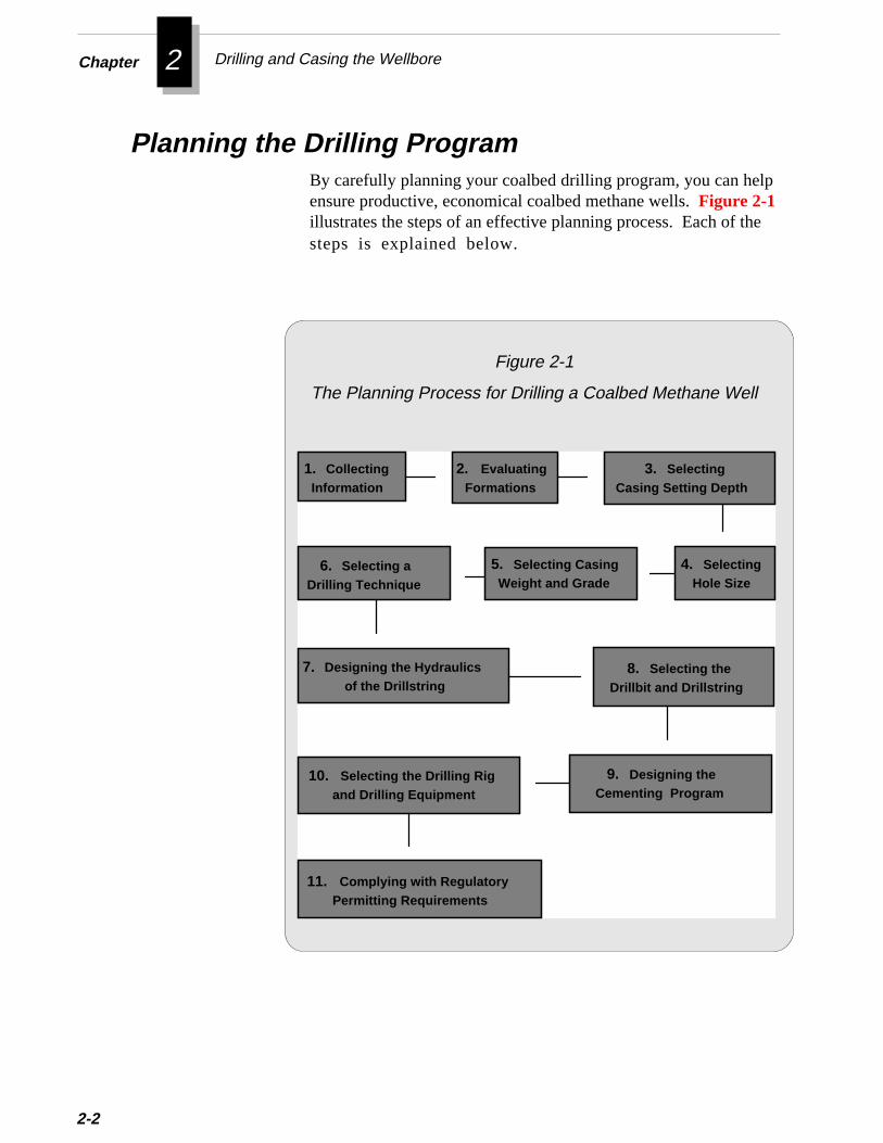
Planning the Drilling ProgramBy carefully planning your coalbed drilling program, you can helensure productive, economical coalbed methane wells. Figure 2-1illustrates the steps of an effective planning process. Each of thsteps is explained below.
Figure 2-1
The Planning Process for Drilling a Coalbed Methane Well
1. CollectingInformation
5. Selecting CasingWeight and Grade
3. SelectingCasing Setting Depth
4. SelectingHole Size
2. EvaluatingFormations
7. Designing the Hydraulicsof the Drillstring
6. Selecting aDrilling Technique
11. Complying with Regulatory Permitting Requirements
9. Designing theCementing Program
10. Selecting the Drilling Rig and Drilling Equipment
8. Selecting theDrillbit and Drillstring
outionnindal try
eind
ly
heo
Planning the Drilling Program
Before you can make informed decisions about a drilling program, ymust learn as much as possible about coalbed drilling and producoperations in your area. Begin by collecting any well informatioavailable from offset coalbed methane operators. You may also fsome of this information recorded as public information at your locand state oil and gas regulatory agencies. Specifically, you shouldto obtain this well information:
❖ Formation depth, pressure, and production
❖ Type of coal and non-coal formations
❖ Well logs
❖ Rig type and drilling assembly
❖ Drilling fluid specifications
❖ Casing program
❖ Drilling problems encountered
❖ Stimulation and completion methods
In addition, you should talk with drilling contractors who havsubstantial experience in your area of interest. You should try to fout:
❖ Types of rigs, surface and downhole equipment commonused
❖ Drilling problems typically encountered
❖ Drilling procedures for eliminating problems
❖ Equipment cost and availability
You should also become familiar with considerations for preparing twell site for drilling operations. For information on this topic, refer t
1. Collecting Information
2-3

Chapter 2 Drilling and Casing the Wellbore
2-4
Chapter 1 of this guide.
Finally, you should consult with your local and state oil and gasagencies and environmental agencies to learn what laws and regu-lations you must follow.
After collecting offset well information, you should evaluate anyavailable well logs and drilling records to determine approximatedepths for prospective coal intervals. You should also attempt toidentify any potential problem zones, such as:
❖ Depleted zones that may cause lost circulation
❖ Sloughing shales
❖ Overpressured zones or water disposal zones
❖ Fresh water aquifers
Accurately identifying prospective coal intervals and problemzones will help you to design an effective casing and cementingprogram.
To select the casing string and drilling equipment, you must firstdetermine at which depths to set casing in the wellbore. The casingsetting depths will depend primarily on these factors:
❖ Fracture gradients of coal seams and adjacentformations
❖ Regulatory requirements
❖ Drilling problems
❖ Isolation of coal seams
Before selecting the casing setting depth, you first must determinethe fracture gradient, or pressure per foot of depth, required tofracture the coal seams and adjacent formations. In general, youshould set casing through zones that have a fracture gradient that is
2. Evaluating Formations
3. Selecting Casing Setting Depth
s.st
Planning the Drilling Program
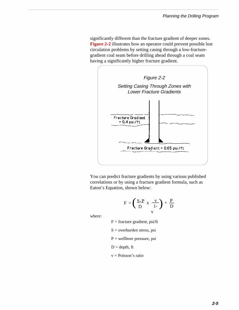
significantly different than the fracture gradient of deeper zoneFigure 2-2 illustrates how an operator could prevent possible locirculation problems by setting casing through a low-fracture-gradient coal seam before drilling ahead through a coal seamhaving a significantly higher fracture gradient.
Figure 2-2
Setting Casing Through Zones withLower Fracture Gradients
hed as
You can predict fracture gradients by using various publiscorrelations or by using a fracture gradient formula, suchEaton’s Equation, shown below:
where:F = fracture gradient, psi/ft
S = overburden stress, psi
P = wellbore pressure, psi
D = depth, ft
v = Poisson’s ratio
(F = S-P D
x ) v 1-v
+ PD
2-5
Chapter 2 Drilling and Casing the Wellbore
2-6
e
hele,t0
-uses-
ee,ryou
n
Fracture gradients for coal seams in the Black Warrior Basin rangfrom as low as 0.5 psi/ft to over 1.0 psi/ft.
To determine proper casing setting depths, you must also consider trequirements of state and local regulatory agencies. For exampregulatory agencies governing the Black Warrior Basin require thayou set a minimum of 300 feet of surface casing in wells up to 400feet deep.
You should also consider potential drilling problems when determining casing setting depths. Set casing to isolate zones that may caproblems such as water influx, sloughing shales, or abnormal presures.
Finally, when selecting casing setting depths, you should isolatprospective coal seams to optimize well completions. For examplset surface casing deep enough to eliminate drilling problems, but tnot to set surface or intermediate casing across coal intervals that yplan to complete. A well completed through two strings of casing(surface and production casing) will likely be much less productivethan a well completed through only one string.
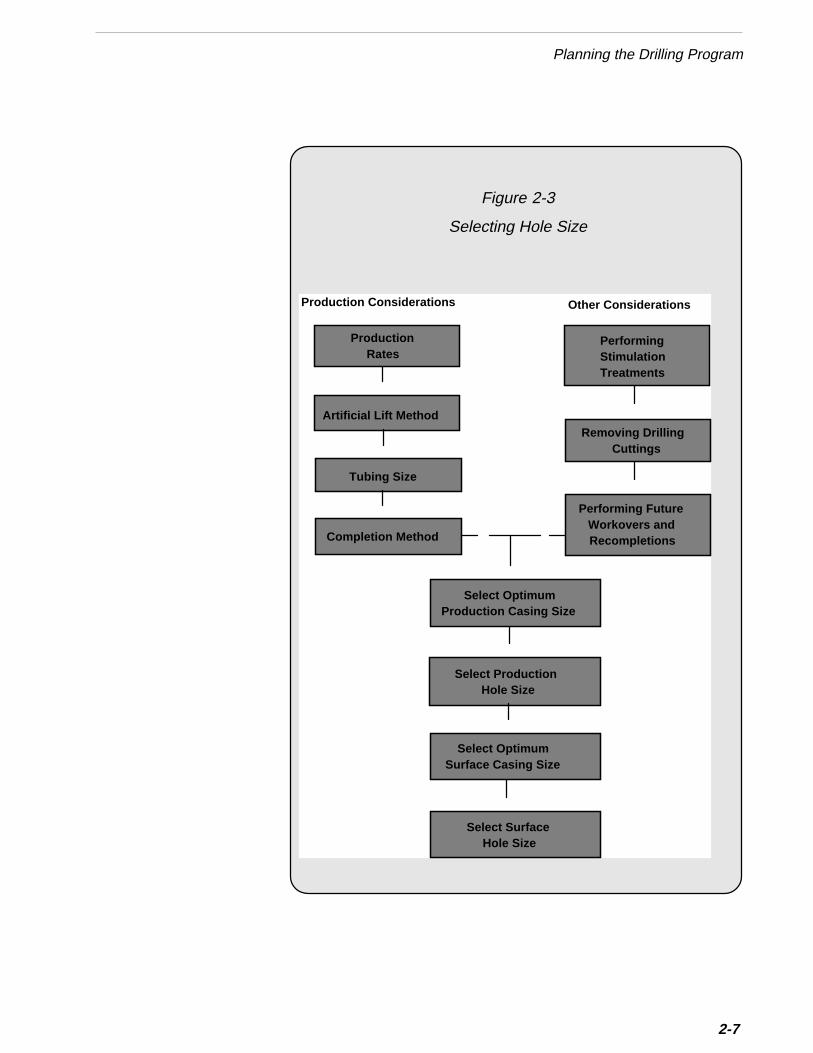
4. Selecting Hole SizeBefore the rest of the drilling program can be designed, you mustfirst determine the sizes of the hole to be drilled. You should basethe hole sizes on the casing program rather than selecting casingbased on a pre-selected hole size. By carefully planning the holeand casing sizes, you can avoid many operational problems later ithe life of the well.
This section will guide you through the steps for determiningproper hole sizes. Figure 2-3 illustrates the steps in this process.Each of these steps is explained below.
2-7
Planning the Drilling Program
Figure 2-3
Selecting Hole Size
ProductionRates
Production Considerations Other Considerations
Artificial Lift Method
Completion Method
Select ProductionHole Size
Select OptimumProduction Casing Size
Removing DrillingCuttings
Tubing Size
PerformingStimulationTreatments
Performing FutureWorkovers andRecompletions
Select OptimumSurface Casing Size
Select SurfaceHole Size
Chapter 2 Drilling and Casing the Wellbore
2-8
Production RatesTo select optimum hole size, you should begin by esti-mating the expected water and gas production ratesfor the well. You may be able to obtain these esti-mates from offset well data, as explained earlier in CollectingInformation.
Artificial Lift MethodNext, you must decide what method of artificial lift youwill use to remove water from the wellbore. Becausecoalbed methane reservoirs typically have very lowpressures, you must select a lift system that will main-tain a low wellbore water level to minimize bottomhole pressureand optimize gas production. For more information on selecting anartificial lift system, refer to Chapter 6.
Tubing SizeWhen you design the artificial lift system, you will de-termine the optimum production tubing size to install inthe well. This decision is based on the type and size oflift system you select as well as the estimated produc-tion rates. For more information on selecting tubingsize, refer to Chapter 4.
Selecting an insufficient tubing size may pre-vent you from effectively dewatering a coalbedreservoir, and thus severely limit ultimate gasp r o d u c t i o n .
Completion MethodNext, you should consider how you will complete thewell. Your choice of an open hole or cased hole completion willinfluence the amount and size of production casing you run. Forexample, you must select casing sizes that will accommodate thediameter of completion tools (e.g., perforation guns, slotting tools,underreamers) you will need to complete the well. For moreinformation on designing the well completion, refer to Chapter 4.After determining the optimum casing string for your tubing andcompletion requirements, you should consider several other factors.
❈❈❈❈❈ Important
Production Considerations in Selecting Hole Size
Planning the Drilling Program
o
nghst
n
eal
-ous.redrof
nytethe
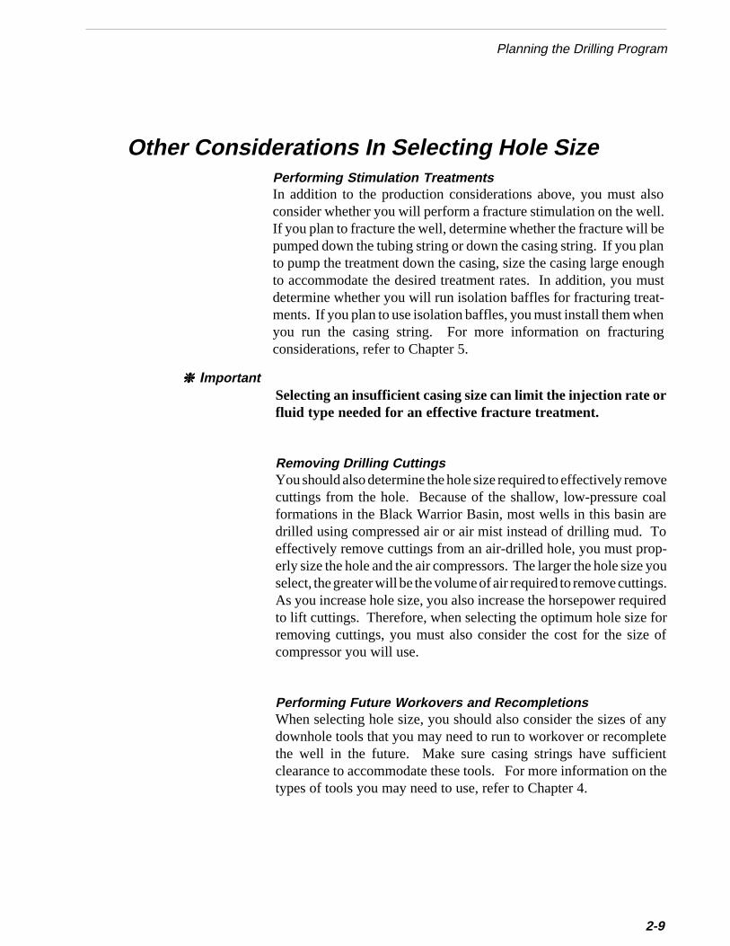
Other Considerations In Selecting Hole SizePerforming Stimulation TreatmentsIn addition to the production considerations above, you must alsconsider whether you will perform a fracture stimulation on the well.If you plan to fracture the well, determine whether the fracture will bepumped down the tubing string or down the casing string. If you plato pump the treatment down the casing, size the casing large enouto accommodate the desired treatment rates. In addition, you mudetermine whether you will run isolation baffles for fracturing treat-ments. If you plan to use isolation baffles, you must install them wheyou run the casing string. For more information on fracturingconsiderations, refer to Chapter 5.
Selecting an insufficient casing size can limit the injection rate orfluid type needed for an effective fracture treatment.
Removing Drilling CuttingsYou should also determine the hole size required to effectively removcuttings from the hole. Because of the shallow, low-pressure coformations in the Black Warrior Basin, most wells in this basin aredrilled using compressed air or air mist instead of drilling mud. Toeffectively remove cuttings from an air-drilled hole, you must properly size the hole and the air compressors. The larger the hole size yselect, the greater will be the volume of air required to remove cuttingAs you increase hole size, you also increase the horsepower requito lift cuttings. Therefore, when selecting the optimum hole size foremoving cuttings, you must also consider the cost for the size compressor you will use.
Performing Future Workovers and RecompletionsWhen selecting hole size, you should also consider the sizes of adownhole tools that you may need to run to workover or recomplethe well in the future. Make sure casing strings have sufficienclearance to accommodate these tools. For more information on ttypes of tools you may need to use, refer to Chapter 4.
❈❈❈❈❈ Important
2-9
Chapter 2 Drilling and Casing the Wellbore
2-1
hhee-
---less
c-
t
eld.
r
Analyzing Production Considerations and Other Considerations
Next, independently evaluate the hole size requirements of eacproduction and other consideration explained above. Then select toptimum production casing size that best satisfies all these requirments.
For additional guidance in evaluating hole sizes for particular applications, consult with drilling contractors, service company representatives, and well operators who are experienced in drilling, stimulating, completing, and producing coalbed methane wells. These peopcan explain the specifications and operation of their tools and discuthe requirements of your particular operation.
Selecting Optimum Production Casing SizeSelect the production casing size that best satisfies all of the prodution and other considerations explained above.
Many operators in the Black Warrior Basin run 4-1/2 inch or 5-1/2inch production casing. Most of the wells at the Rock Creek Projecwere cased with 5-1/2 inch production casing.
Selecting Production Hole SizeThe size of the production casing you select will help determine thsize of the production hole required. The hole size you select shoube large enough to prevent the casing from sticking while being runIn addition, the hole size should allow sufficient annular space toprovide an effective cement job. Many operators in the Black Warrio
0
her
Basin drill a 7-7/8 inch production hole to accommodate a 5-1/2 incproduction casing string. For additional guidance in selecting a prophole size, refer to Figure 2-4.
2-11
Planning the Drilling Program
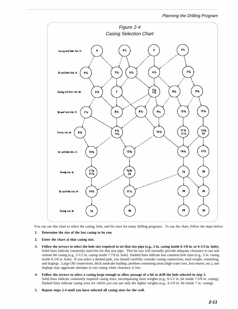
1. Determine the size of the last casing to be run.
2. Enter the chart at that casing size.
3. Follow the arrows to select the hole size required to set that size pipe (e.g., 5 in. casing inside 6-1/8 in. or 6-1/2 in. hole).Solid lines indicate commonly used bits for that size pipe. This bit size will normally provide adequate clearance to run andcement the casing (e.g., 5-1/2 in. casing inside 7-7/8 in. hole). Dashed lines indicate less common hole sizes (e.g., 5 in. casinginside 6-1/8 in. hole). If you select a dashed path, you should carefully consider casing connections, mud weight, cementing,and doglegs. Large OD connections, thick mudcake buildup, problem cementing areas (high water loss, lost returns, etc.), anddoglegs may aggravate attempts to run casing when clearance is low.
4. Follow the arrows to select a casing large enough to allow passage of a bit to drill the hole selected in step 3.Solid lines indicate commonly required casing sizes, encompassing most weights (e.g., 6-1/2 in. bit inside 7-5/8 in. casing).Dashed lines indicate casing sizes for which you can use only the lighter weights (e.g., 6-1/8 in. bit inside 7 in. casing).
5. Repeat steps 2-4 until you have selected all casing sizes for the well.
You can use this chart to select the casing, hole, and bit sizes for many drilling programs. To use the chart, follow the steps below:
Casing Selection ChartFigure 2-4
Chapter 2 Drilling and Casing the Wellbore
e of large the thesing the the
acealso
f thedrillrfacesize,
ld
nsnt
ipal
2-12
Selecting Optimum Surface Casing Size
The size of the production casing you select will determine the sizthe surface casing string to run. You should select surface casingenough to accommodate the bit needed to drill the hole forproduction casing string. If you plan to run a cement collar onproduction string, make sure the drift diameter of the surface cais large enough to accommodate the bit required to providemaximum hole size for the cementing collar, as specified bycementing collar manufacturer.
Many operators in the Black Warrior Basin run an 8-5/8 inch surfcasing string. Most of the wells at the Rock Creek Project were cased with 8-5/8 inch surface casing.
Selecting Surface Hole SizeThe size of the surface casing you select will determine the size osurface hole required. Many operators in the Black Warrior Basin a 12-1/4 inch surface hole to accommodate an 8-5/8 inch sucasing string. For additional guidance in selecting surface hole refer to Figure 2-4.
Before beginning your casing and cementing program you shouobtain a casing and cementing handbook from one of the majoroilfield service companies. This handbook provides specificatioand other useful information on casing and cementing equipmeand materials.
When you design a casing string, you must consider three princforces:
• Burst Pressure
• Collapse Pressure
• Tensile Load
5. Selecting Casing Weight and Grade
ure.
the
u youa-
it,dad
hes also
Planning the Drilling Program
on
e is
inggh
Burst PressureBurst pressure refers to a condition of unbalanced internal pressBurst pressure is probably the most important factor in designingthe coalbed casing string because the pipe will likely experiencegreatest pressures during fracturing stimulations, when treatingpressures can exceed 5000 psi. You can estimate the treatingpressures required by using the fracture gradients you predictedwhen determining casing setting depth (step 3 above). Once yohave estimated fracture gradients for the coal seams of interest,can select the proper casing weight and grade. For more informtion on casing specifications, refer to a service company casinghandbook.
Tensile LoadTensile load is the force exerted on a joint by the weight of thejoints below it. Because each joint supports all the weight belowthe greatest tension occurs at the top of the string. Most coalbewells in the Black Warrior Basin are shallow; therefore, tensile lois not a primary consideration for this area.
Production casing is usually available in sizes ranging from 4.5 incto 7.0 inches and in a variety of weights and grades. Casing is
Collapse pressure is the unbalanced external pressure imposedthe pipe. The worst operational case is for the pipe to be emptywith a normal hydrostatic pressure gradient exerted on it from thoutside. The greatest differential pressure exerted on the casingmost likely to occur during flowback of a fracture treatment orduring the later stage of production when pressure inside thewellbore decreases significantly. You should design the casingstring for this worst case scenario.
Typically, water levels in coalbed wells are pumped down tominimize hydrostatic pressure and optimize gas production. Thecollapse pressure becomes a more significant factor in deepercoalbed wells. Because of the relatively shallow wells (500-3500feet) in the Black Warrior Basin, casing collapse has posed fewproblems in this area. However, the collapse strength of the casmay be reduced by mechanical operations such as slotting or hidensity perforating.
Collapse Pressure
2-13
Chapter 2 Drilling and Casing the Wellbore
rllal
eeete
. Aefne
2-14
classified as API (American Petroleum Institute) standard casing olimited service casing. API standard meets all specifications for wathickness, outside diameter, inside diameter, drift, collapse, internyield, and joint yield strength ratings for its respective grade.
Limited service casing is also called “mill reject” because one or morspecifications does not meet API standards. However, limited serviccasing may also be tested to 80 percent of the minimum yield as sforth by API specifications. Therefore, to reduce cost you may choosto use limited service casing for some applications.
Typical casing grades are F-25, H-40, J-55, K-55, C-75, N-80,C-95, and P-110. These grades represent the strength of the casingvariety of casing weights and wall thicknesses is also available for usaccording to well conditions. Select the size, weight, and grade oproduction casing based on the individual well design and completiotechnique. For more information on completing coalbed methanwells, refer to Chapter 4.
Before ordering casing, find out the limitations of casing weightand length for the rig you will use to run the tubulars. Byordering Range Two casing and tubing, which have lengths of28-32 feet, you may be able to use a smaller, less costly rig.
Most Black Warrior Basin operators complete coalbed methanewells simply using a production string set through a shallow sur-face casing. They generally run 5-1/2 inch casing in a 7-7/8 inchhole. The surface casing usually consists of 300 feet of 8-5/8 inchcasing set in a 12-1/4 inch hole.
Casing Used in the Black Warrior Basin
Using casing smaller than 4-1/2 inch (O.D) limits the size ofproduction tubing you can run inside it. If the casing/tubingannulus is too small, the flow path for gas will be restricted andthe annulus can easily plug.
❈❈❈❈❈ Important
▲▲▲▲▲ Caution
fs
rs
Planning the Drilling Program
To select the most effective drilling technique for your area ofinterest, you must consider the geologic and reservoir conditions othe coal basin. Generally, wells drilled in the eastern United Statetarget shallow coal beds (less than 4000 feet) in geologically olde(Pennsylvanian) and more competent formations. Operators in thiarea usually employ relatively simple drilling techniques. Incontrast, complex drilling techniques are used to drill wells in thewestern United States, which usually target younger (Cretaceous)formations that are deeper, over-pressured, and less competent.
6. Selecting A Drilling Technique
lss
e
e to
these
ng
of
utsite
Operators in the Black Warrior Basin frequently drill coalbed welusing the rotary-percussion technique, with air or air-foam mist athe circulating fluid. Figure 2-5 shows a comparison of the con-ventional rotary and the rotary-percussion drilling techniques.
Rotary-percussion drilling has become a standard technique in thBlack Warrior Basin because it typically yields higher penetrationrates and lower drilling costs than conventional rotary drilling. Inaddition, the rotary-percussion technique minimizes formationdamage because it uses no drilling mud.
In the northern end of the Black Warrior Basin, where the surfacformations are hard, coalbed wells are often drilled from surfacetotal depth using the rotary-percussion technique. In this area,drilling with a tri-cone rotary bit yields lower penetration ratesbecause at shallow depths it is not possible to apply sufficientweight on the bit.
In the southern end of the Black Warrior Basin, however, where softer Cretaceous formations are encountered from surface to adeep as 500 feet, the surface hole must be drilled using a tri-conrotary bit with drilling fluid (usually water) to prevent hole col-lapse. After drilling through the Cretaceous formations and settisurface casing, drillers usually switch to rotary-percussion drillingto achieve greater penetration rates in the harder formations.
Most of the coalbeds in the Black Warrior Basin are water satu-rated, low pressure, low permeability formations. In some parts the basin, little formation water flows into the wellbore duringdrilling, and air circulation can easily remove not only cuttings, bany produced water as well. When the wells at the Rock Creek
2-15
Chapter 2 Drilling and Casing the Wellbore
2-16
were drilled, a mixture of water and liquid soap was added to thecompressed air to enhance lifting of cuttings and cleaning of thehole. For more information on removing drilling cuttings, refer tostep 7, Designing the Hydraulics of the Drillstring.
Figure 2-5
Conventional Rotary and Rotary-PercussionDrilling Techniques

Planning the Drilling Program
In most cases, you can achieve the greatest penetration rate in hardformations by using a percussion bit with an air hammer. However, ifyou encounter a particularly hard formation when drilling with a tri-coneroller bit, you may switch from air to water to better cool the bit. All ofthe wells at the Rock Creek site were drilled using only air or air mistas the circulating fluid.
The main benefits and limitations of drilling with air circulation are:
Benefits❖ Eliminates possible filtration damage to coal
❖ Reduces loss-of-circulation problems
❖ Provides straighter holes because of less weight-on-bit
❖ Lower cost because no mud is used
❖ Faster drilling rate
Limitations❖ Unable to effectively lift large volumes of water
❖ Bit gauge can degrade appreciably during drilling
❖ Drillpipe can wear excessively from sandblasting effect
❖ Air compressor packages may not be available in some areas
When drilling in some parts of the Black Warrior Basin, you mayencounter permeable faults and fracture systems that produce largevolumes of water. Because state and federal environmental regulationsprohibit overflow of drilling pits, you must stop air drilling if a wellproduces water faster than it can be hauled away. This problem canseverely jeopardize projects with economics based on the lower cost ofair drilling.
Water producing zones can also cause loss of circulation problems withwellbores that are rotary drilled with fluid. Using conventional lostcirculation materials to control fluid loss has sometimes proven ineffec-tive and expensive. In addition, lost circulation materials may greatlyreduce the effective permeability and the gas producing potential of coalformations. Similarly, squeeze cementing to control water influx andloss of returns can be prohibitively expensive.
2-17
Chapter 2 Drilling and Casing the Wellbore
2-18
To solve these water problems, a drilling contractor in the BlackWarrior Basin has successfully used a system of alternately drillingwith air mist and water. The contractor has successfully demon-strated that if the wellbore is generally competent, you can drillwith air mist until all surface recovery tanks are full of producedformation water. You can then continue drilling by switching towater circulation until the surface storage tanks are pumped dry.By continuing this process of alternating air mist and water drill-ing, you can drill to the total depth of the well. This technique ofalternating drilling fluids can minimize excess water productionand allow you to reach target depths without pumping potentiallydamaging lost circulation materials or expensive squeeze cementtreatments. For more information on this technique, refer toAdditional References at the end of this chapter.
To optimize the alternating fluid technique, you should strive tocirculate a mixture of air and water that will balance the pressure inthe hole. That is, the mixture should neither permit a large influxof water into the wellbore nor a large loss of fluid to formations.This balance requires carefully monitoring the drilling pits andadjusting the water/air mixture. When you achieve the propermixture, the pits will neither lose nor gain large amounts of water.
If you use the alternating fluid technique, you should use bits thatdo not contain jets. (Air bits usually do not have jets installed.) Ifyou must use jets, they should be large enough to keep standpipepressure below maximum compressor pressure. (For more infor-mation on drillbits, refer to step 8, Selecting the Drillbit andDrillstring ).
When drilling with a rotary-percussion assembly, you cannotuse the technique of alternating air mist and water. Percussionhammers operate pneumatically and will not tolerate largeamounts of water.
Alternating Drilling with Air Mist and Water
▲▲▲▲▲ Caution
-
o
-
i-al.
Planning the Drilling Program
Designing a hydraulics program for the drillstring involves select-ing the proper combination of drilling fluids and drillbits. Anoptimum drilling hydraulics program can accelerate drilling rateand lower rig cost. A poorly designed program can slow penetration, increase cost, and possibly damage the formation.
The design of the hydraulics program for deep coalbed methanewells can be complex. If you plan to drill in an area where drillingfluids are needed to control formation pressure and maintainwellbore integrity, you should consult with experienced drillingengineers. They can use hydraulics software to determine theoptimum design for your application. Service companies can alsassist you in designing an effective hydraulics program.Fortunately, most coalbed methane wells in the Black WarriorBasin can be drilled with air and thus require a relatively simplehydraulics program. The three main considerations in designingthe hydraulics program are:
• Minimizing Damage to Coal Formations
• Effectively Cleaning the Hole
• Cooling and Lubricating the Bit
By minimizing damage caused by invasion of drilling fluids intoprospective coal intervals, you can help ensure optimum gas production rates. You should drill holes using air, air mist, or waterinstead of drilling muds, when possible, to minimize formationdamage. Air circulation exposes the coal to less solids and chemcal additives, and it exerts minimal hydrostatic pressure on the co
If you need to use a drilling fluid to control formation pressures,you should carefully select the type of fluid and additives. Ifformation pressures permit, the safest and most economical fluidto use is fresh water with a small amount of bentonite to addviscosity. Using heavy muds could plug or even fracture the coal.You should use them only as a last resort. You should also avoidchemicals that could damage the coals.
Minimizing Damage to Coal Formations
7. Designing the Hydraulics of the Drillstring
❈❈❈❈❈ Important
2-19
Chapter 2 Drilling and Casing the Wellbore
an
tion.i-
um
eibil-
t
a-
2-20
Effectively removing drilling cuttings from the hole increases thepenetration rate and thus reduces rig time. Keeping the hole clecan also increase the life of the drillbit. Air drilling removescuttings from the hole effectively if the air is circulated at anadequate rate.
Determining the Air Rate Needed to Lift CuttingsThe optimum air circulation rate is a function of drilling depth, theannular area between drillpipe and hole, and the rate of penetraIn 1957, R. R. Angel published a set of charts that show the minmum air circulation rate at various depths for given drillpipediameters and hole sizes. These charts are based on the minimannular velocity of 3000 ft/min, which is necessary to lift cuttingsfrom the hole. Angel converted this velocity to volumetric flowrates based on depth, the annular areas for various pipe and holsizes, and the effects of bottomhole pressures and air compressity on the downhole volumes.
Recent research has shown the actual volumetric rate of flownecessary to efficiently lift cuttings is slightly higher than thevolumes in the Angel curves. Some drilling contractors in theBlack Warrior Basin recommend using an air volume at least 25%greater than the values in the Angel curves.
Determining the Air Pressure Needed for Air DrillingTo effectively clean the hole, you must also inject air at sufficienpressure to keep cuttings from falling back. Determining therequired surface, or injection, pressure in advance of drilling willhelp you to properly size the air compressor for the job.
You can estimate the required surface air pressure using the eqution below:
Psurf = Pf + Pah + Pcsg
where:Psurf = the compressor discharge pressure at the surface
Pf = the friction pressure of air in the drillpipe and the frictionpressure of air, water, and cuttings in the annulus
Effectively Cleaning the Hole
Planning the Drilling Program
Pah = the total hydrostatic head in the annulus minus the hydro-static head in the drillpipe.
Pcsg = the backpressure on the discharge line to the drilling pit.(This pressure should be zero under normal drillingconditions.)
The most difficult variable to estimate is Pah. For example, if youare drilling with air and there is no influx of formation water intothe annulus, there would be air in the drillpipe and air plus cuttingsin the annulus. Thus, Pah could be near zero, depending on theamount of cuttings in the annulus. However, if water flows into theannulus, Pah would be essentially equal to the hydrostatic pressurecreated by that water influx.
Because it is difficult to predict the amount of water influx, it islikewise difficult to accurately estimate the surface air pressurerequired. In the Black Warrior Basin, drilling contractors havefound they can drill a 7-7/8 inch hole with an air compressor capableof an air injection rate of 2000 cfm. Most compressors used for airdrilling have a maximum allowable discharge pressure of 350 psi. Ifyou need greater pressure, you can route the primary compressorthrough a booster compressor.
If you are drilling with an air percussion hammer, you shouldconsult the hammer manufacturer’s air pressure charts for thesurface pressure required to operate the hammer.
Using Air Mist to Remove CuttingsTo enhance removal of cuttings, you can use a mixture of air, water,and chemicals to create an air mist drilling fluid. Common chemicaladditives for air mist systems are detergents for foaming, lubricantsfor reducing friction, corrosion inhibitors, and viscosifiers.
Because air mist fluids have a higher viscosity than air fluids, theycan effectively lift cuttings at a much lower flow velocity than air.For example, air circulation usually requires a flow velocity of3000 ft/minute to effectively clean the hole, whereas a stable foamfluid may require a velocity of only 200-300 ft/minute. The highflow velocity needed for air drilling can erode and enlarge the hole,greatly reducing the ability to remove cuttings.
2-21
Chapter 2 Drilling and Casing the Wellbore
thedso
uds-
of
n
n
n.
ld
2-22
To effectively remove cuttings from an air or air mist hole, youmust properly size the hole and the air compressors. The largerhole size you select, the greater will be the volume of air requireto remove cuttings. Therefore, as you increase hole size, you alincrease the horsepower required to lift cuttings. When selectingthe optimum hole size for removing cuttings, you must also con-sider the cost for the size of compressor you will use.
Cooling and Lubricating the BitIn wells drilled with drilling mud, the mud helps reduce the largeamount of heat that is generated as the bit cuts through rock. Malso help to reduce the torque and drag on the drillstring by lubricating the wellbore.
When drilling with air or air mist, you do not have the advantagedrilling fluid in the wellbore to cool the bit. However, speciallydesigned tri-cone rotary bits are available for air drilling. Thesebits contain ports that allow air to circulate around the bearings ithe bit to dissipate heat and extend bit life.
When using a common rotary bit with air mist drilling, the water ithe mist helps to cool the bit. If you encounter a particularly hardformation when drilling with a tri-cone roller bit, you may switchfrom air to water to better cool the bit. You will find more infor-mation on drillbits for air drilling in the next section.
The drillstring includes the drillbit, drill collars, and drillpipe. Insome areas, you may also use stabilizers to control hole deviatio
DRILLBITSWhen determining the bit program for a coalbed well, you shouconsider these factors:
❖ Bit cost
❖ Formation types
❖ Drilling techniques
❖ Hydraulics
❖ Rig cost
8. Selecting the Drillbit and Drillstring
ouboutcs.ot, And
les step
tri-
oste for
isblyore
it angr-
e of
ry soft istheyou
Planning the Drilling Program
Before selecting the bits for your drilling program, the data that ygathered as discussed in Section 1 should provide information aformation types, drilling techniques, and commonly used hydrauliThe bit records of offset wells should be included in that data. If nthis type of information can often be obtained from bit suppliers. review of the offset bit records will help to estimate the number atypes of bits to use.
You will determine the size of the drillbits based on the sizes of the hofor the surface casing and production casing, which you selected in4, Selecting Hole Size, earlier in this chapter.
The bits most commonly used in drilling coalbed methane wells arecone rotary bits and percussion bits.
Tri-Cone Rotary BitsThe sealed bearing,tri-cone rotary bit is the most common and the mversatile bit used in the oil and gas industry. These bits are availabldrilling a variety of different formations.
A specially designed tri-cone rotary bit is available for air drilling. Thbit contains ports which allow air to flow through the bearing assemfor cooling. Most tri-cone air bits are open port bits and are thus msusceptible to corrosion than sealed bearing tri-cone rotary bits.
If you drill with air only, a tri-cone air bit may provide the longest blife. However, if you plan to alternate drilling air mist and water,sealed bearing bit will likely last longer. You should consider usisealed bearing bits to provide the flexibility of drilling with either aimist or water.
Percussion bitsPercussion bits are used in combination with air hammers. This typbit is used exclusively for drilling hard formations with air or air-foammist. As discussed earlier in step 6, Selecting a Drilling Technique,percussion drilling is necessary when drilling hard formations at veshallow depths. Percussion bits with air hammers cannot be used inor sloughing formations. A typical percussion bit and air hammershown in Figure 2-5. If you encounter a soft formation, such as Cretaceous in the Southwestern part of the Black Warrior Basin, should use tri-cone rotary bits with fluid.
2-23
Chapter 2 Drilling and Casing the Wellbore
2-24
At the Rock Creek project, the surface holes were drilled withrotary bits because the first several feet of the hole are in a softformation. Because the State Oil and Gas Board of Alabamarequired less surface casing then than it does now, drilling wascontinued with the rotary bit down to the setting depth for thesurface casing. After setting surface casing, the production holes atRock Creek were drilled with percussion bits and air hammers.
Drill CollarsTo select the number of drill collars for the drillstring, you mustconsider the weight-on-bit that the operator or drilling contractor hasdetermined necessary to drill the hole. You can determine the opti-mum weight-on-bit by conducting drilloff tests or by estimating itfrom offset bit records. For more information on determining weight-on-bit, you may consult with drilling contractors in your areas ofinterest as well as drillbit suppliers.
When air drilling, the drillstring and bottomhole assembly (BHA) aresubjected to high vibration loads. This vibration is often extreme onthe bottomhole assembly and the connection between the BHA and thedrillpipe, especially when drilling hard formations. To protect thedrillstring and the drillstring/BHA connection, you should design thedrillstring so that the neutral point between axial, tensile, and com-pressive stresses during normal drilling is located in the drill collars.You can calculate the length of drill collars needed to achieve thiscondition by using this equation:
Length of drill collars = BW ,ft(BF) (CW)
where:
BW = Desired bit weight, lb
BF = Buoyancy factor, dimensionless(The BF for air is 1.0 because the collar weights aremeasured in air.)
CW = Collar Weight (in-air), lb/ft
Planning the Drilling Program
le
,
t,
nsre
hat
Industry experts recommend adding ten percent to this calculationto account for unforeseen forces such as bounce, hole friction, hodeviation, etc.
Operators in the Black Warrior Basin typically run enough 6-inchcollars to provide a weight-on-bit of approximately 5000pounds/inch for tri-cone bits and 500 pounds/inch for air-hammerbits.
Stabilizers are sometimes run in the drillstring to control holedeviation. The operator must usually decide what arrangement ofstabilizers, if any, to run. When determining the type and numberof stabilizers to run, you should consider the desired weight-on-bitpenetration rate, and type of formations to be drilled. To learnwhat arrangements of stabilizers work best in your area of interesyou should consult with drilling contractors in the area.
In most parts of the the Black Warrior Basin, drilling contractors donot use stabilizers because controlling hole deviation is not aproblem. Most of the wells in the basin are drilled with air or airmist. Because air drilling requires less weight-on-bit than fluiddrilling, there is less tendency for the bit to “walk,” or deviate.
However, in a few parts of the Black Warrior Basin stabilizers areneeded to prevent deviation. These are areas where the formatioare stressed by extensive faulting and folding. When stabilizers aused, the typical bottomhole assembly includes:
❖ Drillbit
❖ Percussion hammer
When selecting drillpipe, you should base your selection on theworst case drilling scenario. If you are drilling wells in a devel-oped area, consult with drilling contractors in the area. They likelyhave gained enough experience to recommend drillpipe designs twork effectively in that area. In the Black Warrior Basin, mostdrilling contractors use 4-1/2 inch drillpipe. For more informationon designing drillstrings, refer to Additional Resources at the end ofthis chapter.
Drillpipe
Stabilizers
2-25

Chapter 2 Drilling and Casing the Wellbore
ug
k-
rearea.t
n the
2-26
❖ Short drill collar
❖ First stabilizer
❖ Full drill collar
❖ Second stabilizer
Check ValvesYou should install check valves at specific intervals in thedrillstring to:
❖ Prevent backflow of cuttings into the drillstring duringconnections or other shut-downs that would otherwise plthe bit.
❖ Reduce the volume of air that must be bled off when maing a connection.
To learn what combination of check valves works best in your aof interest, consult with drilling contractors experienced in the aFor the Rock Creek Project, check valves were usually placed aintervals of 400 feet in the drillstring.
Because coals have a low mechanical strength, you must desigcementing program to prevent the weight of the cement fromfracturing the coal formations. You can avoid fracturing coalformations during cementing by selecting proper cement andadditives and proper cementing techniques.
To select a cement that is strong enough to provide a sufficientbond, but that will not fracture the coal because of its weight,follow these procedures:
Selecting Cement and Additives
9. Designing the Cementing Program
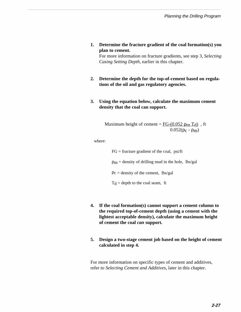
Planning the Drilling Program
1. Determine the fracture gradient of the coal formation(s) youplan to cement.For more information on fracture gradients, see step 3, SelectingCasing Setting Depth, earlier in this chapter.
2. Determine the depth for the top-of-cement based on regula-tions of the oil and gas regulatory agencies.
3. Using the equation below, calculate the maximum cementdensity that the coal can support.
Maximum height of cement = FG-(0.052 ρm Td) , ft0.052(ρc - ρm)
where:
FG = fracture gradient of the coal, psi/ft
ρm = density of drilling mud in the hole, lbs/gal
ρc = density of the cement, lbs/gal
Td = depth to the coal seam, ft
4. If the coal formation(s) cannot support a cement column tothe required top-of-cement depth (using a cement with thelightest acceptable density), calculate the maximum heightof cement the coal can support.
5. Design a two-stage cement job based on the height of cementcalculated in step 4.
For more information on specific types of cement and additives,refer to Selecting Cement and Additives, later in this chapter.
2-27

Chapter 2 Drilling and Casing the Wellbore
2-28
Selecting Cementing TechniquesUse cement placement techniques that will minimize stress on thecoal formations. For information on these techniques, refer toCasing and Cementing the Wellbore, later in this chapter.
After you have designed the casing, drillstring, and hydraulicsprograms, you can select a drilling rig. If the availability of drill-ing rigs is limited in your area, you may have to modify the casing,drillstring, and hydraulics programs to meet the rig’s capabilities.
When selecting a rig for your drilling program, consider each ofthese factors explained below:
• Type of Drilling Rig
• Air Compressors
• Derrick
• Drive System
• Blowout Preventers or Diverter System
• Other Rig Equipment
Type of Drilling RigYou can normally use a portable (truck-mounted) rig to drillshallow coalbed methane wells. Portable rigs are normally moreeconomical than conventional rigs because they require less rig-upand rig-down time. Most wells drilled in the Black Warrior Basinare drilled with portable rigs.
Air CompressorsIn the Black Warrior Basin, most wells are drilled with compressedair. To determine the number and size of air compressors neededto drill a particular well, you must first estimate an air circulationrate and maximum injection pressure. For information on estimat-ing air circulation rate and injection pressure, refer to step 7,Designing the Hydraulics of the Drillstring, earlier in this chapter.
10. Selecting the Drilling Rig and Drilling Equipment
l
Planning the Drilling Program
At the Rock Creek site, an auxiliary compressor was used to pro-vide the additional volumes of air at higher pressures needed todrill deeper formations and formations that produced large volumesof water. The auxiliary compressor ensured sufficient air velocityto carry cuttings to the surface. It also helped prevent flooding thedownhole air percussion hammer with excessive water.
In general, you can choose from two types of drive systems. Themost common system is the conventional rotary table and kelly usedin most oil and gas fields.
The other is a top-drive system. The top-drive system uses a powerswivel on top of the drillstring to rotate the string. The power swiveleliminates the rotary table and kelly. Because the top-drive systemrequires fewer drillpipe connections, it can reduce drilling time aswell as provide greater safety.
In the Black Warrior Basin, drilling companies use both conventionadrives and top drives. The selection of a drive system is mostly amatter of personal preference and rig availability.
Drive System
You should select a rig with a derrick weight capacity that willenable the operator to use the designed drillstring and to run thedesired casing string. The maximum loading on the rig usuallyoccurs when running casing. You should also select a derrickheight (single or double stand) that fits your well location size andis compatible with the depth of your well. The increased cost for arig that can run doubles (two joints of pipe connected), may bejustified in deeper wells because it could significantly reduce triptime. However, a rig with a single-stand derrick is usually suffi-cient for most coalbed wells.
In the Black Warrior Basin, drilling contractors generally use singleand double rigs. Some portable rigs have a derrick capacity up to350,000 pounds, which is more than adequate for drilling in theBlack Warrior Basin.
Derrick
2-29
Chapter 2 Drilling and Casing the Wellbore
.
2-30
Blowout Preventers or Diverter SystemThe blowout preventer (BOP) stack used to drill most conventionalwells includes a set of pipe rams, blind rams, and an annularpreventer. However, drilling contractors in the Black WarriorBasin do not use a conventional BOP stack. Instead, they use adiverter system. The diverter system consists of an annularpreventer called a rotating head and two remotely-controlled valveswhich open to separate flowlines that vent to the reserve pit.
Other Rig EquipmentThough the equipment listed below is usually supplied by thedrilling contractor, you should verify that the equipment has theproper capacity and other specifications to meet the requirements ofthe job.
Blooey LineThe return line, or blooey line, carries the exhaust air and cuttings fromthe annulus to the flare pit. The blooey line should be long enough tokeep dust from interfering with rig operations. In most cases, the lineshould be 100-300 feet long.
You should size the blooey line so that the internal cross-sectional areais about 10% greater than the annular area of the near-surfaceborehole. This slightly larger area is needed to compensate for thefluid energy loss that occurs as the air and cuttings make a 90-degreeturn from vertical flow to horizontal flow under the rig floor.
The end of the line should terminate downwind from the prevailingwind direction. You should also make sure the end of the blooey lineis tied down securely.
Chemical PumpsChemical pumps are used to inject water or chemical foamers into thewellbore during drilling.
Orifice Plate MeterA standard orifice plate meter is normally used to measure the rate ofair circulation. The size of the orifice plate selected will depend on thecirculation rate needed to effectively clean the hole. To ensureaccurate readings, make sure the meter has been calibrated recentlyAn alternative to the orifice plate meter is the turbine meter. If no
the
t theore
ed
reerillf
rs
ryarel
esra-r.erto
m inits
nty
Planning the Drilling Program
meter is available, you can estimate the air rate based on the size ofcompressor and the suction and discharge pressures.
Pump GaugesAccurate pressure gauges should be installed on the standpipe and acompressor discharge. These gauges can be used to monitor wellbconditions and predict potential downhole problems.
Bleed-Off LineA bleed-off line should be installed to bleed pressure off the standpipand the drillpipe down to the top check valve. This pressure is blethrough the blooey line.
Burn PitA burn pit at the end of the blooey line can be used to catch any wellboeffluent (such as chemicals or hydrocarbons) that would otherwiscontaminate the reserve pit. Because few chemicals are used to dcoalbed methane wells in the Black Warrior Basin, contamination othe reserve pit is usually not a problem. Thus most drilling contractovent the blooey line directly to the reserve pit.
Before spudding a well, you must satisfy all state and federal regulatorequirements. In some states, two or more regulatory agencies involved in permitting wells. Typically, one agency regulates actuawell activities (drilling permits, well completion permits, pit prepara-tion, production allowables, etc.). However, several other agencimay regulate the environmental aspects of site selection, site prepation, spill prevention, spill clean-up, and disposal of produced wateFor information on selecting and preparing a field site, refer to Chapt1. For information on treating and disposing produced water, refer Chapter 8.
In some states, obtaining necessary permits requires approval froseveral different agencies which work interdependently. Therefore,many cases you may have to obtain all required environmental audand/or permits before the oil and gas regulatory agency will graapproval to spud a well. Consequently, permitting can be a length
11. Complying With Regulatory Permitting Requirements
2-31
Chapter 2 Drilling and Casing the Wellbore
ra
e
l
2-32
process, depending on the number of agencies involved and theirelationships with each other. In some states, the process to permit well could take as long as six months to a year.
When planning a coalbed project, you should read and understandthe state and local regulations that may affect your operation. Inmost states, the initial application for a permit to drill a well mustinclude a certified survey showing the exact well location. Somefield procedures, such as cementing and testing casing, may requirthat you notify the proper agency and obtain approval beforeproceeding on to the next step in the operation.
Though permitting requirements vary from state to state, manyrequirements are similar. To get some sense of typical regulationsfor coalbed methane operations, refer to the summary ofAlabama’s well permitting procedures, shown in Appendix A.
Drilling the WellboreDrilling practices for coalbed methane wells can vary significantlyfrom one coal basin to another. The depth and geology of the coalseams generally determine the drilling techniques and equipmentthat work best. When you are new to an area, you often can avoidmany drilling problems and save considerable money by applyingthe experience gained by other operators in that area. Try to keepan open mind about unfamiliar practices that at first seem inappro-priate. They may turn out to be the most successful and cost-effective methods.
During the past 10 years, operators and drilling contractors in theBlack Warrior Basin have learned much about drilling coalbedmethane wells through trial and error. They have found the generaprocedures below particularly effective for drilling coalbed meth-ane wells in the Black Warrior Basin:
1. Before beginning drilling, stake down the return (Blooey)line and chain down all compressed air lines. An air linethat blows out can seriously harm workers if it is not prop-erly secured.
▲▲▲▲▲ Caution
ileing
these
aybitse ofe
orthe0
a-
n
Drilling the Wellbore
2. If there is any loosely compacted fill dirt at the surface, installconductor casing through it. Drill a 16-inch surface hole andinstall 14-inch conductor pipe down to solid earth. Backfilland compact dirt around the outside of the conductor pipe.The conductor casing provides for return of drilling water whdrilling the surface hole and for cement slurry while cementsurface casing.
3. Drill the initial part of the surface hole (20-30 feet) using a tri-cone roller bit with compressed air.
◆ If the surface formations are unconsolidated (such asCretaceous section in the Black Warrior Basin), drill theformations using tri-cone rotary bit with drilling fluid.
4. After drilling initial surface hole or after reaching competentformations, switch from the tri-cone bit to an air-hammerand hammer-bit assembly to drill the remainder of the hole.
◆ If you encounter a hard formation at a shallow depth, you muse a percussion bit with an air hammer. Conventional may yield low penetration rates at shallow depths becausthe inability to apply sufficient weight on the bit whildrilling.
◆ When drilling 7-7/8 inch hole, the optimum rate of rotation fa percussion bit and air hammer is 10-30 RPM, and optimum rate of rotation for a tri-cone rotary bit is 50-6RPM.
◆ Drill with air, whenever practical, to achieve the bestpenetration rate and to minimize damaging the coal formtion with liquid drilling fluid invasion.
◆ Do not use an aerated drilling fluid (air and water mixed)when using an air-hammer assembly. Water can flood aair hammer.
5. Circulate compressed air at a rate that lifts cuttings andwater to the surface.
❈❈❈❈❈ Important
2-33
Chapter 2 Drilling and Casing the Wellbore
2-34
◆ If you use the “Angel” curves or charts from a drillbitcompany to determine the air circulation rate needed toeffectively lift cuttings, add at least 25% to these values.
The Angel curves show circulation rates required for airdrilling. These curves are presented in Volume Require-ments for Air and Gas Drilling, R.R. Angel, Gulf Publish-ing Company, Fourth Printing 1985.
◆ If the drilling cuttings are fine dust instead of large angularpieces, you should increase the air circulation rate.
Fine dust is created when cuttings are pulverized by the bitinstead of being removed from the hole. This actionreduces the penetration rate and the bit life. For moreinformation on keeping the hole clean, see Designing theHydraulics of the Drillstring, earlier in this chapter.
◆ If you encounter a hard formation that causes a largedecrease in penetration rate, switch from air to an air mistdrilling fluid to help cool the bit.
6. If you encounter a formation that produces significantwater when drilling with a tri-cone rotary bit, you mayhave to switch from air to water circulation to effectivelylift cuttings to the surface. If you are drilling with a per-cussion bit and air hammer, you may have to switch to atri-cone rotary bit with water circulation.
◆ Once you begin circulating water, you must continue usingsome water to drill the rest of the hole. If you switch backto just air after using water, you risk mixing dry and wetcuttings and causing severe plugging in the drillpipe-casingannulus.
◆ If you are drilling with water, add ordinary laundry deter-gent to the water to create a foam that will help clean upthe hole.
7. If the well begins to flow while drilling, switch to a heavy-weight clear water or mud drilling fluid to control forma-tion pressure.
▲▲▲▲▲ Caution
Drilling the Wellbore
Use drilling mud and other additives only if clear heavy-weight fluids are not available or are not sufficient tocontrol formation pressure. Drilling mud invasion into thecoal may cause formation damage and may permanentlydestroy the productivity of the well.
8. Monitor and control weight on bit to optimize penetrationrate and drilling hydraulics.
◆ In the Black Warrior Basin, the optimum weight-on-bit fora tri-cone bit is approximately 5000 lb/inch and 500 lb/inchfor a percussion bit.
9. Drill at least 250 to 300 feet below the deepest target coal seamto provide adequate sump for logging, fracturing, and pro-duction operations.
10. After drilling to the total depth of the well, circulate amixture of air, water and soap, until returns are free ofcuttings and the water is clean. You may also circulate waterwith a viscous pill to clean up the hole.This practice will eliminate excessive fill in the hole and makecasing installation easier.
11. After the drillbit is removed from the hole, measure thediameter of the bit to make sure the diameter of the hole willprovide the required clearance for the casing and casinghardware.
◆ If the bit has been worn below the minimum diameterrequired, you will have to ream the hole to the appropriatesize with a bit or hole opener.
❈❈❈❈❈ Important
For more information on drilling the wellbore, refer to the AdditionalResources at the end of this chapter.
▲▲▲▲▲ Caution
2-35
Chapter 2 Drilling and Casing the Wellbore
ststdr-nt,al
gg
a
ngtg
al..ont
e
2-3
Coring the WellboreAnalyzing core samples obtained from wells is one of the earliemethods of formation evaluation, and it continues to be the moreliable method of obtaining detailed formation descriptions anspecific rock properties. Some of the most important coalbed resevoir data are obtained from cores. These data include gas contedesorption rate, adsorption isotherms, cleat and fracture data, corank, gas quality, and porosity.
This section explains the equipment used for three different corinmethods as well as important considerations and guidelines for corinoperations:
• Coring with a Drilling Rig
• Coring with a Coring Rig
• Coring with Sidewall Tools
• Special Considerations for Coring
• Guidelines for Coring with a Rig
Coring with a Drilling RigIn conventional oil and gas fields, cores are usually obtained withdrilling rig during drilling operations. However, this method is notoften used to core coalbed methane wells because it requires pullithe drillstring to retrieve the core. The trip time can allow significangas to escape from the core sample. In addition, coring with a drillinrig is usually more expensive than the other coring methods.
The conventional coring barrel assembly consists of a coring bit,finger type “catcher,” an outer barrel, and a floating inner barreCoring bits may be drag bits, rolling cutter bits, or diamond coring bitsThe inner barrel contains a check valve (or a dropped ball sealed a seat) at the top, which allows flow upward out of the barrel, but nodownward into the barrel. This check valve diverts the drilling fluid(usually water) from the drillpipe to the bit via the annulus between thouter barrel and the inner barrel. This designprevents the drillingfluid from eroding the core.
6
by.aneto to
ed tot thend
ly,ithip-
bit,llarre
more
field
hich
t the
es
Coring the Wellbore
Coring with a Coring RigWhen coring with a dedicated coring rig, you can retrieve the corepulling the drillstring (as in conventional coring) or by wirelineOperators in the Black Warrior Basin usually core coalbed methwells with a coring rig and then retrieve the core with wireline minimize the amount of gas lost. They generally use a coring rigobtain at least one core for each of their fields. The cores are usdetermine the reservoir and mechanical properties mentioned abeginning of this section. This coring method is a reliable arelatively inexpensive way to gather this critical data.
To retrieve cores by wireline, you will need a hoisting assembincluding a wireline reel, sheave, and wireline lubricator, along wthe normal surface drilling equipment. Additional subsurface equment includes a special coring drill collar and bit; a coring barrel, and bit plug; and a wireline guide and overshot. The special drill coand bit are part of the drillstring. The coring barrel and bit plug a
The primary advantages of coring with a drilling rig are:
❖ Can obtain a large-diameter core. Larger cores provide arepresentative sample of the coal seam
❖ Can recover a high percentage of the formation cored
❖ Requires no additional surface equipment
❖ Provides a larger wellbore, which allows using standard oilequipment for completion, production, andworkover operations
The primary disadvantages of coring with a drilling rig are:
❖ Must pull drillstring to recover the core
❖ May lose an excessive amount of gas from the core, wadversely affects estimates of gas content
❖ Requires good stratigraphic control to accurately seleccoring point
run inside the drillstring. During normal drilling, the bit plug isinstalled inside the special drill collar. The bit plug drills the insidarea that the core bit does not drill. Prior to coring, the bit plug i
2-37
Chapter 2 Drilling and Casing the Wellbore
2-38
pulled with the wireline overshot, and it is replaced with the coringbarrel. The coring barrel (and core catcher) is dropped inside thedrillpipe and it automatically latches into the drill collar. After the corehas been cut, the barrel (with the core inside) is pulled with the wirelineovershot.
The primary advantages of retrieving cores by wireline are:
❖ Can cut and recover consecutive cores without pulling thedrillstring
❖ Does not require continuous coring. Can alternate coring anddrilling without pulling the drillstring
❖ Allows quicker retrieval of the core, which reduces the amountof gas lost before the core is tested
❖ Usually lower cost
The primary disadvantages of wireline coring are:
❖ Requires considerably more surface equipment
❖ The diameter of the core is limited. The diameters for wirelineretrievable cores range from 1-1/64" to 2-13/32".
Sidewall cores are usually taken from the side of the borehole usinga wireline tool that is equipped with hollow bullets that are fired intothe formation. These bullets are attached to the gun body by shortcable wires. To use the sidewall coring tool, the gun is positioned atthe selected depth and then each of the bullets are individually firedelectronically from the surface. The bullets are then withdrawn by thecable wires. Sidewall coring is performed during open hole loggingoperations after the hole is drilled.
The primary advantage of wireline sidewall coring is:
❖ Can take cores from any depth after the hole is drilled
Coring With Sidewall Tools
The primary disadvantages of wireline sidewall coring are:
❖ Samples may be too small for complete and accurate analysis
d
neoole-llye
wallinen
thectselpd
ringng
re
as.
ct
Coring the Wellbore
❖ Samples may be partly crushed or at least severely altere
To reduce the possibility of crushing the core inherent in wirelisidewall coring, a newer sidewall coring tool was developed. This tuses a rotary sidewall drill rather than a bullet gun. The wirelinconveyed rotary tool has a diamond bit that drills the core horizontafrom the side of the wellbore. Rotary sidewall coring may providcores that are less disturbed than those obtained with wireline sidecoring. However, this method is usually more expensive than wirelsidewall coring. The rotary sidewall coring tool is offered by HalliburtoLogging Services.
■■■■■ Unconsolidated or highly fractured formations can be coredwith a rubber sleeve core barrel.Because the inner diameter of a rubber sleeve is smaller than diameter of the core, the rubber sleeve stretches and contraaround the core as it enters the catcher. The rubber sleeve may hpreserve the core enough to allow identification of fractures anlithological features.
In many respects, coring coalbed methane wells is similar to coconventional wells. However, you may improve your coalbed corioperations by considering the guidelines below:
■■■■■ If coring with a coring rig, retrieve the core with a wirelineassembly to minimize the amount of gas lost from the core.Cores that are quickly retrieved by wireline usually provide moreliable gas desorption data.
■■■■■ Fill the wellbore with fluid before coring to reduce the amountof gas lost from core samples.Cores taken from air-drilled holes may lose a large amount of g
■■■■■ Data on coal joints and/or cleats can be obtained by orientedcoring. Oriented coring allows the directional measurement ofgeologic features.Oriented coring was used successfully at the Rock Creek projeto determine cleat direction, rock joint orientation, faults, etc.
Special Considerations for Coring
2-39
Chapter 2 Drilling and Casing the Wellbore
2-40
Guidelines for Coring with a RigWhen coring coalbed methane wells with either conventional orwireline retrievable tools, you may find the guidelines below useful:
■■■■■ Select core points with competent rock above and below thecoal interval.Competent core above and below the coal in the core barrel willincrease the probability of successfully retrieving the core.
■■■■■ Run the core barrel into the hole slowly.Running in the hole at excessive speeds may damage the barrel ifa dogleg is hit or may cause the barrel to plug.
■■■■■ Begin coring with a light bit weight and low rotary speed andthen gradually increase weight and speed as cutting is estab-lished.
■■■■■ Use low pump rates when coring to avoid washing away thecoal.
■■■■■ Monitor the pump pressure to ensure that fluid is passing overthe bit and that the core barrel is not plugged. If the pumppressure increases, raise the bit off bottom. If raising the bitdoes not decrease pump pressure, the core barrel isprobably plugged and should be pulled.
■■■■■ A sudden decrease in penetration rate that is not caused by aformation change could indicate the core barrel is plugged orjammed and should be pulled.
■■■■■ When finished coring, pull the drillstring very slowly.Pulling the drillstring too quickly can create suction, which canpull the core out of the barrel.
g
e
d
Casing and Cementing the Wellbore
Casing and Cementing the WellboreA proper wellbore casing and cementing job is critical to thesuccessful completion of a coalbed methane well. When designinthe casing program, you should select the proper equipment andmaterials for your application. If you have not read Selecting HoleSize and Selecting Casing Weight and Grade earlier in this chapter,you may want to do so now.
This section will help you in:
• Selecting Casing Hardware
• Selecting Cement and Additives
• Running the Casing String
• Cementing the Casing String
You should select casing hardware that is compatible with thecementing, stimulation, and completion plan for the well. Becausof the marginal economics for coalbed wells, most coalbed meth-ane operators try to minimize investment in casing hardware.However, savings on casing hardware can be easily overshadoweby formation damage or loss in well control caused by lack ofproper equipment.
Before beginning your casing and cementing program you shouldobtain a casing and cementing handbook from one of the majoroilfield service companies. This handbook provides specificationsand other useful information on casing and cementing equipmentand materials.
Operators in the Black Warrior Basin use a variety of casinghardware when running casing. The purpose and procedure forusing several of these tools is described below:
Selecting Casing Hardware
2-41
Chapter 2 Drilling and Casing the Wellbore
t
ed
ohe
theonhe,ther
ral-ture
2-42
Cement Wiper Plug
A cement wiper plug is a rubber plug (or rubber with a cast alumi-num insert) used to separate the cement slurry from the displace-ment fluid to prevent contamination and/or dilution of the tail endof the slurry. Because water is normally used as the displacemenfluid in coalbed methane wells, slurry contamination is usually nota problem, but dilution could occur. The wiper plugs are mountedin a cementing head at the top of the casing so they can be releasdirectly behind the slurry without shutting down.
Guide Shoe
A guide shoe is a short heavy-walled pipe or collar with a roundnose on bottom. The shoe is installed on the bottom of the casingto prevent the casing from hanging on ledges or other boreholeirregularities. The guide shoe is attached to the bottom of theproduction casing before running the casing into the hole.
Float CollarA float collar contains an internal valve which prevents backflowof cement up the casing string during cementing operations. It alsincreases the buoyancy of the casing, thus reducing the load on trig while running casing. In addition, the float collar serves as astop for the cement wiper plug so that all of the cement is notinadvertently pumped out of the casing. The float collar is usuallyinstalled one joint above the guide shoe.
Casing CentralizersCasing centralizers ensure the casing remains in the center of wellbore during cementing operations to allow for cement coverage all sides of the casing string. Centralizing the casing improves tprobability of effective cement jobs and zone isolation. In additioncentralization reduces the negative effects of bends or doglegs in casing which could hamper artificial lift equipment and workoveoperations.
When cementing across a coal seam, you should always run centizers above and below each seam that may be produced at some futime.
gensfer
r
t
t
Casing and Cementing the Wellbore
The number of centralizers that you should run in the rest of the casinstring depends on the hole size and the amount of hole deviation. Whrunning 5-1/2 inch casing in a 7-7/8 inch hole, most service companierecommend running a centralizer at least every third or fourth joint. Ithe hole is highly deviated, you will need to space the centralizers clos
A float shoe is a combination guide shoe and float collar. It has a roundnose, and it contains a check valve and may also contain a catcher fothe wiper plug. A latch-down plug may be used to prevent backflowin case the check valve fails. A float shoe can be used instead of a floacollar and guide shoe.
Float Shoe
Baffle plates are installed in the casing, usually instead of or along withother cementing equipment. The plates are installed between theguide shoe and the first joint of casing or between the first two jointsof casing if you would like to have one joint filled with cement at thebottom of the string. Baffle plates are held in place by the pin end ofthe casing or tool (such as a float shoe) below them.
The latch-down plugs wipe the casing free of cement during displace-ment. The wiper plug latches in an internal catch in the baffle plate toprevent flow back into the casing after cementing.
Baffle Plates with Latch-Down Plugs
A cement basket is a tool attached to the outside of the casing toprovide support for the cement column while it cures. Cement basketscan be placed above zones that have low fracture gradients to preventhem from breaking down. If cement baskets become filled withdebris, they may inhibit reciprocation of casing.
Cement Basket
together.❈❈❈❈❈ ImportantInadequate centralization of the casing can prevent an effectivecement job.
2-43
Chapter 2 Drilling and Casing the Wellbore
p
sr.e.
g
atse
.e
2-44
External Casing Packer
An external casing packer, which is run in the casing string, formsa seal between the casing and the hole. If running casing in a deewell or in a well with weak coal zones (i.e., coals with low fracturegradients), you can run an external casing packer in the casingstring to help support the cement column and reduce the pressurethe cement exerts on the coal formation.
To operate the packer, a plug is pumped down to a seat below thepacker such as a baffle plate or cementing collar. Once the plug iseated, pressure is applied above it to open the ports to the packeWhen the ports open, cement can be pumped. The cement fills thpacker and inflates the packer element against the wall of the holeAfter the packer is inflated, the ports in the cementing collar abovethe packer can be opened by applying additional pressure, allowincement to flow into the annulus above the packer.
External casing packers are normally used in coalbed methanewells to protect the lower-most coal seam in open hole comple-tions. This technique is described in Chapter 4 - Completing theWell.
Multi-Stage Cementing ToolA multi-stage cementing tool is used when the required column ofcement is too large to be pumped in a single slurry. The toolcontains a plug catcher and side ports. To activate the tool, a plugis dropped, and then the casing is pressured up. This pressure sethe plug in the plug catcher to seal off the casing and open the sidports. Then the second cement stage is pumped, and it flows outthe side ports to the annulus. This tool is run with the casing stringIt is installed in the casing at a depth above the calculated top of thprimary cement and above the coal formation to be isolated fromcement intrusion.
For more information on stage cementing, refer to Cementing theCasing String, later in this chapter.
/
Casing and Cementing the Wellbore
er
e
Operators have used several different types of cement in coalbedmethane wells. The simplest type used is Class A, which is acommon portland cement. Class A cement has a density of 15.6 ibgal without additives. Adding bentonite to Class A cement canlower its density by increasing the maximum allowable volume ofwater that can be added to the cement. Adding 6% bentonite canreduce the density to 13.5 lb/gal.
You can use Class A cement for relatively shallow coals if the coalwill support its density. The maximum depth recommended forClass A is 6000 ft. Class A cement is more economical than theother premium cements.
Selecting Cement and Additives
Cement Slurry Designs
Class A Slurry
Because coals have a low mechanical strength, you must select aproper cement density to prevent the weight of the cement fromfracturing the coal formations. For information on calculatingproper cement density, refer to “Designing the Cementing Pro-gram” earlier in this chapter. After you have determined thecorrect cement density for your well, you can then select the propcement.
Experience in the Black Warrior Basin has demonstrated that youcan usually avoid potential cementing problems and accommodatthe tight economic constraints of coalbed methane completions byusing one of the following cement slurry applications:
• Class A Slurry
• Pozmix® Slurry
• Silicalite Slurry
• Foam Slurry
• Specialized Slurry
2-45
Chapter 2 Drilling and Casing the Wellbore
/
s
2-46
Pozmix ® Slurry
Pozzolans are siliceous or siliceous/aluminuous materials which youcan use to lower the density of cement slurries, much the same asbentonite. If you are working in an area where the coal formation willsupport cement densities of 12 to 14 lb/gal, you can use a Pozmix®
slurry to provide zone isolation and adequate compressive strength.
A typical pozzolan blend is 50% Class A and 50% pozzolan. Thismixture is commonly called "50/50 Poz." A 50/50 Poz cement has adensity of 14.15 lb/gal. An advantage of pozzolan slurries is theirresistance to corrosive fluids. A disadvantage is their lower compres-sive strength compared to Class A cement.
A Pozmix® cement design which has been used successfully at theRock Creek project is listed below:
1. To mix the lead slurry, combine a 50/50 blend of Pozmix®/Class A cement with 4% total bentonite for a slurry weight of12.7 to 12.8 lb/gal.
2. To mix the tail cement slurry, combine the same mixture asfor the lead cement, but mix at 13.5 lb/gal.You can also mix a tail cement of 15.6 lb/gal using neat cement,if the coal formation will support this weight.
Silicalite Slurry
A Silicalite slurry is a blend of Class A, Pozmix®, and Silicalite.Including Pozmix® and Silicalite in the blend helps reduce thedensity by inceasing the amount of water which may be added to theslurry.
In areas where coals will not support cement densities of 12 to 14 lbgal, a Silicalite cement may work effectively.You can mix aSilicalite slurry with a density from 11 to 13 lb/gal. A typicalSilicalite slurry has a density of 11.5 lb/gal.
Because the properties of silicalite cement are so well suited tocoalbed methane wells, some operators use this slurry even inwellbores strong enough for a higher weight cement. The cement haexcellent fluid loss characteristics, low slurry viscosity, set times
ts,t-bees.
-the
eethlysingare
ingtheent.
e aeres, type
Casing and Cementing the Wellbore
faster than Pozmix® blends, essentially no free water, and highearly compressive strengths.
Operators often use foam cement slurries to cement shallow, lowpressure coalbed methane wells where weak zones would breakdown if a normal density cement were used. If you are working inan area where wellbore integrity requires slurries under 11 lb/gal,you may consider using a foam cement.
Foam cement is usually a mixture of basic cement, foaming agenstabilizing agents, and nitrogen. This combination provides a lighweight cement slurry with a high yield. Foam cement slurry may the most economical if you have nearby access to nitrogen faciliti
If nitrogen is not readily available, you may consider using conventional cement with multistage cementing tools. When comparing cost of using a multistage tool to the cost of using foam cement,be sure to include the drillout cost for the multistage tool.
Foam Slurry
You can use a variety of specialized slurries and additives to mindividual well requirements. For example, if you encounter a higpermeable zone that causes lost circulation, you could seal it off ua thixotropic cement, which sets very quickly. Thixotropic cements also very effective for secondary or remedial cementing.
Some types of light weight cement achieve lower densities by utilizadditives which allow adding more water to the slurry. However, added water lowers the ultimate compressive strength of the cem
If you need a light cement for a primary cement job, you might usspecial cement that incorporates hollow glass beads, or microsphwith a base cement. You can add these hollow microspheres to any
Pumping foam cement at too high a rate may create a higherfriction pressure in the casing annulus than would other typesof cement. This increased friction pressure may offset thebenefit of the lighter weight of foam cement. To fully realizethe benefits of foam cement’s lighter weight, do not pump foamcement at an excessive rate.
Specialized Slurries
▲▲▲▲▲ Caution
2-47
Chapter 2 Drilling and Casing the Wellbore
r
y
n
2-48
of cement to produce slurries ranging in density form 9 to12 lb/gal. This type of slurry can greatly reduce the density of theslurry without significantly reducing the compressive strength ofthe cured cement.
Some glass microspheres may begin to crush at pressures near4000 psi. Because the crush resistance of glass microspheresvaries, you should check with the manufacturer or supplier ofmicrospheres before using them. Though the depth to which glassmicrosphere slurrries can be used is limited, most coalbed methanewells are shallow enough to use them.
Special additives are usually mixed with the base cement to alter oimprove slurry properties. You can use additives to accelerate orretard cement curing, to reduce slurry density, to control fluid loss orlost circulation, or to modify other slurry properties. For example, youcan add calcium chloride or sodium chloride to cement to acceleratethe time required for the cement to set or to hydrate. As mentionedearlier, you also can add pozzolans or bentonite to reduce the densitof the cured cement.
When designing your casing program, consult several different ce-menting company representatives who are trained and experienced icementing coalbed methane wells. They can provide informationabout a variety of additives available for altering slurry properties tomeet the requirements of your particular well.
In areas where leakoff is high, consider the following guidelines:
◆ Add a low fluid loss additive to the slurry. Use an additive thatdoes not delay thickening time or increase slurryviscosity.
◆ Add a lost circulation material such as gilsonite, cellophaneflakes, or walnut shells to help prevent cement contaminationof the fractured coal.
Cement Additives
s,
Casing and Cementing the Wellbore
Before beginning to pump cement, you should follow the proceduresbelow:
1. Several hours before pumping the cement, meet with theservice company people to discuss the goals of the cement joband the responsibilities of each person. Also discuss contin-gency plans for handling possible operational problems.Invite questions or suggestions regarding any aspect of theoperation.
2. Several hours before pumping the cement, conduct a safetymeeting with all people who will be on location during thecementing job. Discuss safe operating procedures, use ofsafety equipment, and contingency plans in case of an emer-gency.
3. Obtain a sample of the actual dry cement mixture (withadditives) that will be pumped.Maintain this sample as a quality control check in case problemsarise on the cement job. You can have it sent to a lab for analysiif necessary.
The following techniques have proven effective in cementingcoalbed methane wellbores in the Black Warrior Basin.
Before the Cementing Job
Cementing the Casing String
4. Install the cementing manifold with plug(s) (from the ce-menting company) on top of the casing.Figure 2-6 shows a cementing manifold similar to the type usedto cement the wells at the Rock Creek project.
5. Pressure test all surface pumping lines with water. Test up tothe maximum anticipated surface pump pressure.
2-49
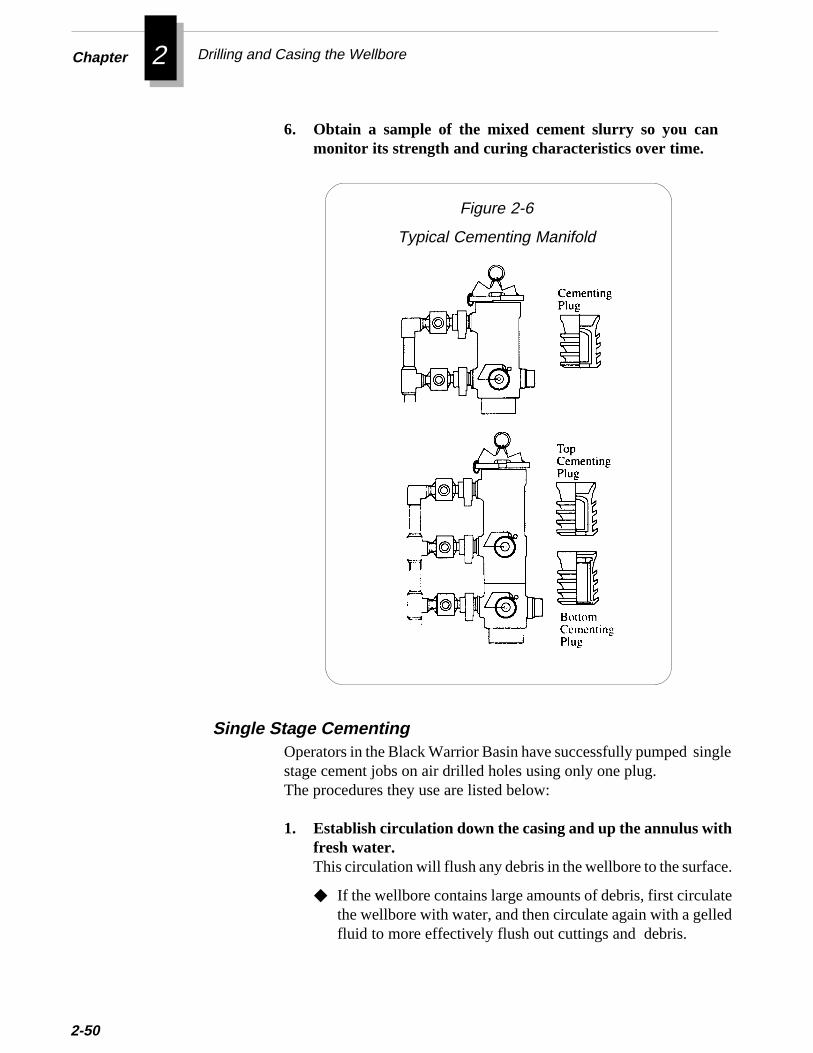
Chapter 2 Drilling and Casing the Wellbore
2-50
6. Obtain a sample of the mixed cement slurry so you canmonitor its strength and curing characteristics over time.
Figure 2-6
Typical Cementing Manifold
le
.
ed
Operators in the Black Warrior Basin have successfully pumped singstage cement jobs on air drilled holes using only one plug.The procedures they use are listed below:
1. Establish circulation down the casing and up the annulus withfresh water.This circulation will flush any debris in the wellbore to the surface
◆ If the wellbore contains large amounts of debris, first circulatthe wellbore with water, and then circulate again with a gellefluid to more effectively flush out cuttings and debris.
Single Stage Cementing
e
e
i-g,ells
Casing and Cementing the Wellbore
-
s
2. Pump the cement slurry.To help ensure the cement slurry distributes evenly around thcasing, reciprocate or rotate the casing string while pumpingthe slurry.
3. Release the plug from the cementing manifold.
4. Pump the displacement fluid (usually fresh water).
5. Pump fluid until the plug “bumps bottom”.When the plug bumps, you will see a sharp increase in surfacpump pressure.
Be careful not to bump the plug so hard that the pressureincrease exceeds the casing burst pressure. Make sure thecementing service company uses a pump operator with enoughexperience to avoid this problem.
If the well was drilled with mud, pump a bottom plug ahead of thecement slurry to wipe the mud from the casing and prevent contamnation of the lead cement. As an alternative to pumping a bottom pluyou can pump a spacer or a mud preflush ahead of the cement. In wdrilled with air and circulated with fresh water, you do not need topump a plug or spacer ahead of the cement.
▲▲▲▲▲ Caution
Pumping the first stage
Multiple Stage Cementing
A common problem with cementing coalbed wells has been formation damage caused by fracturing the coal with cement. Early inthe Rock Creek research project, a stage cementing technique wasuccessfully used to prevent cement from contracting coal seams.The stage cementing procedures below were uesd at the RockCreek project:
1. Calculte the volume of cement needed to fill the annulus from the float shoe to the desired cement top. To determine this volume, use caliper log and add a safety factor of 10-20%.
2-51
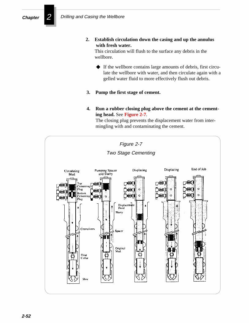
Chapter 2 Drilling and Casing the Wellbore
cu-th a
2-52
2. Establish circulation down the casing and up the annulus with fresh water.This circulation will flush to the surface any debris in thewellbore.
◆ If the wellbore contains large amounts of debris, first cirlate the wellbore with water, and then circulate again wigelled water fluid to more effectively flush out debris.
3. Pump the first stage of cement.
4. Run a rubber closing plug above the cement at the cement-ing head. See Figure 2-7.The closing plug prevents the displacement water from inter-mingling with and contaminating the cement.
Figure 2-7
Two Stage Cementing

af
y
g
Casing and Cementing the Wellbore
5. Pump the volume of displacement water behind the closingplug needed to move the plug to the bottom of the casing.You should see a sharp increase in pump pressure when theplug bumps bottom.After the plug reaches the bottom of the casing, it latches intoseat in the float shoe, preventing any further flow into or out othe annulus.
6. Calculate the volume of cement needed to fill the annulusfrom the cement collar up to the desired height above thecollar.To determine this volume, use the caliper log and add a safetfactor of 10-20%.
7. Drop an opening plug down the casing to the opening plugseat in the cementing collar. See Figure 2-7.
8. After the plug is set, apply pump pressure inside the casingto open the lower sleeve of the cementing collar or to openthe ports of the external casing packer, whichever is used.For more information on cementing collars and external casinpackers, refer to Selecting Casing Hardware, earlier in thischapter.
9. Pump water to establish circulation up the annulus to thesurface. Circulate until returns are clean.
◆◆◆◆◆ If using a cement collar only, allow at least 6 hours be-tween the primary cement job and the second stage.This time is needed for the primary cement to gainsufficient strength to support the second stage.
◆◆◆◆◆ If using an external casing packer, you do not need towait for the primary cement to cure. The packer willsupport the weight of the cement above it.
10. Pump second cement stage into the casing.
Pumping the second stage
2-53
Chapter 2 Drilling and Casing the Wellbore
t
2-54
11. Release a rubber closing plug at the cementing head.See Figure 2-7.
12. Pump water behind the plug to displace the cement intothe annulus. See Figure 2-7.When the closing plug reaches the closing seat, the pumppressure in the casing closes the cementing collar ports to theannulus.
13. Shut in the well for at least 48 hours to allow the cementtime to cure. A curing time of 72 hours is even better.
14. Pump into the casing with water and pressure test thecement to 1000 psi or to the pressure specified by yourcompany.
15. Repeat steps 6 through 14.
Because all of the internal parts of the cementing collar and float shoesare drillable, you can pass drillbits through the casing to completeopen hole intervals below the casing.
For information on completing the well, refer to Chapter4 .
One of the factors critical to the success of primary cementing jobs onmud-drilled holes is the displacement of the mud during cementing.Mud that is not displaced occupies space that should be filled withcement. Channels in the cement are often caused by mud that was noproperly displaced.
Rotating and/or reciprocating the casing during cementing operationshelps to break the gel strength of the mud and thus allows the cementto more effectively displace the mud. Studies have demonstrated thatfor shallow wells (less than 6000 ft) rotating the casing is more
Pumping additional stages
Rotating or Reciprocating Casing while Cementing
h
Casing and Cementing the Wellbore
lo
d
effective than reciprocating the casing. Some operators prefer to botrotate and reciprocate the casing.
Reciprocating casing too rapidly can create pressure surges in thewellbore and fracture the coal. To prevent pressure surges,reciprocate the casing no more than 15-20 ft over a period of twominutes.
Because wells drilled with air contain no drilling mud, rotating orreciprocating the casing is not needed to displace mud. Many air-drilled holes in the Black Warrior Basin have been successfullycemented without moving the casing. However, in air-drilled holeswhich have casing that is not centralized, cement may tend to channeup one side of the casing. In this case, rotating the casing may help tmore evenly distribute the cement around the casing. Using anadequate number of centralizers can help centralize the casing anpromote an effective cement job.
▲▲▲▲▲ Caution
2-55
❖ ❖ ❖
Chapter 2 Drilling and Casing the Wellbore
2-56
Additional Resources
Adams, N.J., and T. Charrier, “ Drilling Engineering: A CompleteWell Planning Approach,” Pennwell Publishing Company, Tulsa,Oklahoma, 1985.
Graves, S.L., J.D. Niederhofer, and W.M. Beavers, “ A CombinationAir and Fluid Drilling Technique for Zones of Lost Circulation in theBlack Warrior Basin,” SPE Paper 12873, SPE Drilling Engineering,February 1986.
Lambert, S.W. et al, “Multiple Coal Seam Well Completion Experi-ence in the Deerlick Creek Field, Black Warrior Basin, Alabama,”Proceedings of the 1987 Coalbed Methane Symposium, The Univer-sity of Alabama, Tuscaloosa, Alabama (November 16-19).
Lambert, S.W., M.A. Trevits, and P.F. Steidl, “ Vertical BoreholeDesign and Completion Practices to Remove Methane Gas fromMineable Coalbeds,” U.S. Department of Energy, CarbondaleMining Technology Center, Carbondale, Illinois, 1980.
3 Wireline Logging
ul.,ed
.
T o evaluate the gas producing potential of a coal formation, yomust first know the reservoir and mechanical properties of the coaKnowing these properties will also enable you to design effectiveeconomical well completions and stimulations. You can determinmost of these coal properties by analyzing data from wireline logs anwhole cores retrieved while drilling the well. After the well iscompleted, you can obtain additional reservoir data from well tests
This chapter will guide you through:
• Sources For Estimating Reservoir Properties
• Open Hole Logging Tools
• Selecting an Open Hole Logging Suite
• Guidelines For Open Hole Logging
• Cased Hole Logging Tools
• Selecting a Cased Hole Logging Suite
• Guidelines For Cased Hole Logging
• Production Logging Tools
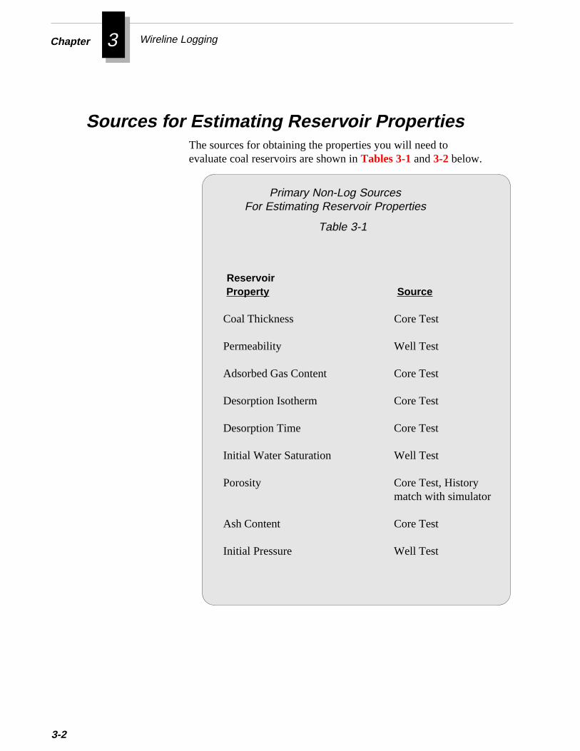
Chapter 3 Wireline Logging
3-2
Sources for Estimating Reservoir Properties
Reservoir Property Source
Coal Thickness Core Test
Permeability Well Test
Adsorbed Gas Content Core Test
Desorption Isotherm Core Test
Desorption Time Core Test
Initial Water Saturation Well Test
Porosity Core Test, Historymatch with simulator
Ash Content Core Test
Initial Pressure Well Test
The sources for obtaining the properties you will need toevaluate coal reservoirs are shown in Tables 3-1 and 3-2 below.
Primary Non-Log SourcesFor Estimating Reservoir Properties
Table 3-1
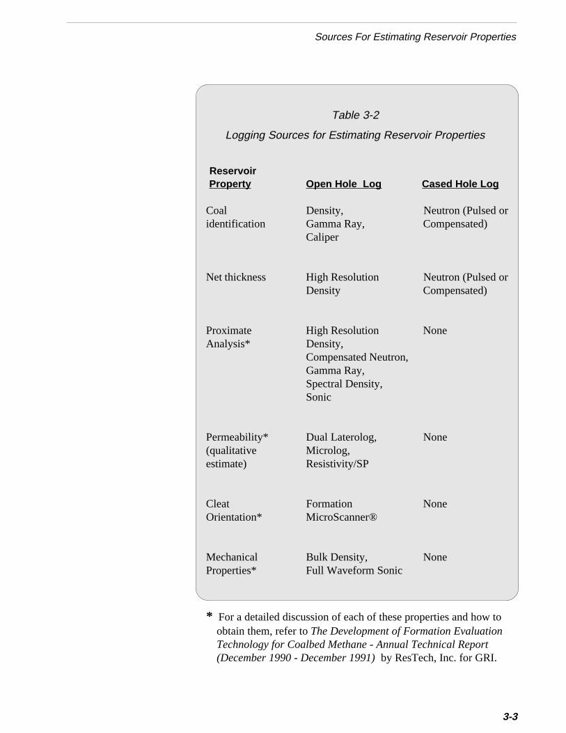
r
to
Sources For Estimating Reservoir Properties
Reservoir Property Open Hole Log Cased Hole Log
Coal Density, Neutron (Pulsed oridentification Gamma Ray, Compensated)
Caliper
Net thickness High Resolution Neutron (Pulsed oDensity Compensated)
Proximate High Resolution NoneAnalysis* Density,
Compensated Neutron,Gamma Ray,Spectral Density,Sonic
Permeability* Dual Laterolog, None(qualitative Microlog,estimate) Resistivity/SP
Cleat Formation NoneOrientation* MicroScanner®
Mechanical Bulk Density, NoneProperties* Full Waveform Sonic
* For a detailed discussion of each of these properties and how obtain them, refer to The Development of Formation EvaluationTechnology for Coalbed Methane - Annual Technical Report(December 1990 - December 1991) by ResTech, Inc. for GRI.
Table 3-2
Logging Sources for Estimating Reservoir Properties
3-3
Chapter 3 Wireline Logging
3-4
Open Hole Logging ToolsTo estimate reservoir properties for coal seams, you can use a varietyof wireline logging tools. This section provides a background for theselogging tools; however, it does not cover log interpretation. Forinformation on interpreting these logs, refer to Additional Resources atthe end of this chapter. The operation of each tool, its response incoalbeds, and important considerations for using the tool are explainedbelow.
When possible, you should log the open hole as soon as practical afterdrilling and cleaning it up. This practice helps to reduce the chance ofdamaging the formation before measuring its properties. It alsodecreases the possibility of encountering hole obstructions whenlogging. You can identify and estimate the thickness of coal seamsusing the logging tools listed below:
• Bulk Density Log
• Spectral Density Log
• Caliper Log
• Natural Gamma Ray Log
• Dual induction/Shallow Induction Log
• High Resolution Induction Logs
Open Hole Logging Tools for Identifying Coal Seams
The density log measures the bulk density of the formation as emittedgamma rays are scattered by the formation. In most non-coalformations, you can relate bulk density to porosity when you know thelithology.
The bulk density log is an excellent tool for identifying and evaluatingcoal seams. Generally, you can identify coal seams by comparing
Bulk Density Log
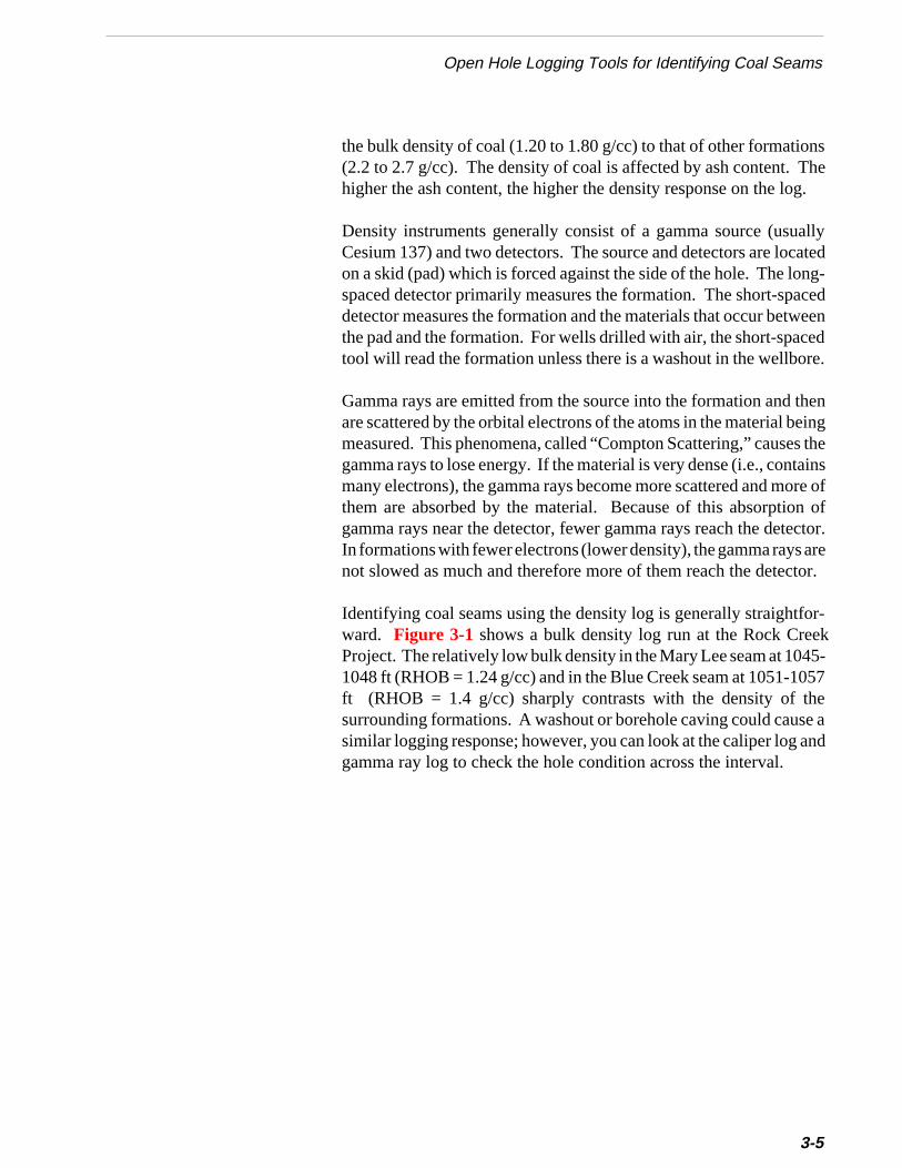
she.
llyatedg-
cedeenede.
ening theins
re of ofctor.re
or.
Open Hole Logging Tools for Identifying Coal Seams
the bulk density of coal (1.20 to 1.80 g/cc) to that of other formation(2.2 to 2.7 g/cc). The density of coal is affected by ash content. Thigher the ash content, the higher the density response on the log
Density instruments generally consist of a gamma source (usuaCesium 137) and two detectors. The source and detectors are locon a skid (pad) which is forced against the side of the hole. The lonspaced detector primarily measures the formation. The short-spadetector measures the formation and the materials that occur betwthe pad and the formation. For wells drilled with air, the short-spactool will read the formation unless there is a washout in the wellbor
Gamma rays are emitted from the source into the formation and thare scattered by the orbital electrons of the atoms in the material bemeasured. This phenomena, called “Compton Scattering,” causesgamma rays to lose energy. If the material is very dense (i.e., contamany electrons), the gamma rays become more scattered and mothem are absorbed by the material. Because of this absorptiongamma rays near the detector, fewer gamma rays reach the deteIn formations with fewer electrons (lower density), the gamma rays anot slowed as much and therefore more of them reach the detect
r-k5-57ee and
Identifying coal seams using the density log is generally straightfoward. Figure 3-1 shows a bulk density log run at the Rock CreeProject. The relatively low bulk density in the Mary Lee seam at 1041048 ft (RHOB = 1.24 g/cc) and in the Blue Creek seam at 1051-10ft (RHOB = 1.4 g/cc) sharply contrasts with the density of thsurrounding formations. A washout or borehole caving could caussimilar logging response; however, you can look at the caliper log agamma ray log to check the hole condition across the interval.
3-5
Chapter 3 Wireline Logging
3-6
Figure 3-1
Bulk Density Log
alat
alel
ises
r
Open Hole Logging Tools for Identifying Coal Seams
Once you determine from the density log that an interval contains a coseam, be sure also to check the caliper log and gamma ray log to verify ththe density response was not caused by a hole washout.
Evaluating seam thickness using log data is directly related to the verticresolution and sample rate of the logging device. The distance of thdetector from the radioactive source strongly influences the verticaresolution of the logging device. Most standard oilfield density tools havea source-to-detector spacing of 18 inches. The vertical resolution of thtool has been improved by increasing the sample rate from every 6 inchto every tenth of a foot. Currently, oilfield density tools can provide aresolution of about 6 inches. The oilfield density logs can be computeenhanced to provide results similar to the density tools available frommineral logging service companies.
Some of the more common matrix densities are listed in Table 3-3.
Table 3-3
Matrix Densities
for Common Formations
Mineral Density (g/cc)
Sandstone 2.65 - 2.70
Shale 2.2 - 2.65
Limestone 2.71
Dolomite 2.83 - 2.89
Anhydrite 2.94 - 3.00
Salt (halite) 2.03
Coal
Anthracite 1.4 - 1.8Bituminous 1.2 - 1.5Lignite 0.7 - 1.5
3-7
Chapter 3 Wireline Logging
t aof
3-8
❈❈❈❈❈ Imp
The density tool available from mineral logging service companieshas a source-to-detector spacing of 0.75 inch and samples data arate of 50 samples per foot. This device has a vertical resolution approximately one inch. Because the mineral logging density toolis smaller in diameter than a standard bulk density tool, make surethe mineral logging tool can offer the log quality for the wellboresize you have drilled.
e
l
indsgalh.
Figure 3-2 shows a comparison of the mineral logging density(high resolution) and the oilfield density (computer enhanced). Thcomparison shows that computer enhancement of the oilfieldlogging measurement is an accurate method for improving verticaresolution. [From The Development of Formation EvaluationTechnology for Coalbed Methane - Annual Technical Report(December 1990 - December 1991) by ResTech, Inc. for GRI]
When using a density log, make sure to question the validity ofdensity measurements across washed out zones. The density toolis a pad device which requires good borehole contact to measureaccurately.
As a guide for determining net pay thickness of coal seams for use reservoir simulators and well test analysis, ResTech, Inc. recommenusing a density cutoff of 1.75 g/cc. The coal thickness obtained usinthis method should be compared to core data (if available). In thin coseams, the density value on the density log can be erroneously hig
ortant

s
-
d
Open Hole Logging Tools for Identifying Coal Seams
Figure 3-2
Comparison of Conventional Density andMineral Logging Density Logs
described earlier. However, in addition to measuring gamma rayfrom “Compton Scattering,” which is indicative of bulk density, it alsomeasures gamma rays from the photoelectric effect, which is indicative of lithology. By comparing these two different gamma raycounts, you can determine the photoelectric absorption index (Pe) an
Spectral Density LogThe spectral density tool is similar to the bulk density tool
3-9
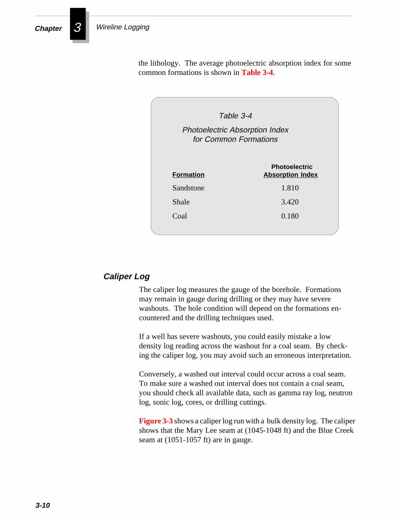
Chapter 3 Wireline Logging
3-10
the lithology. The average photoelectric absorption index for somecommon formations is shown in Table 3-4.
Table 3-4
Photoelectric Absorption Indexfor Common Formations
PhotoelectricFormation Absorption Index
Sandstone 1.810
Shale 3.420
Coal 0.180
Caliper LogThe caliper log measures the gauge of the borehole. Formationsmay remain in gauge during drilling or they may have severewashouts. The hole condition will depend on the formations en-countered and the drilling techniques used.
If a well has severe washouts, you could easily mistake a lowdensity log reading across the washout for a coal seam. By check-ing the caliper log, you may avoid such an erroneous interpretation.
Conversely, a washed out interval could occur across a coal seam.To make sure a washed out interval does not contain a coal seam,you should check all available data, such as gamma ray log, neutronlog, sonic log, cores, or drilling cuttings.
k
Figure 3-3 shows a caliper log run with a bulk density log. The calipershows that the Mary Lee seam at (1045-1048 ft) and the Blue Creeseam at (1051-1057 ft) are in gauge.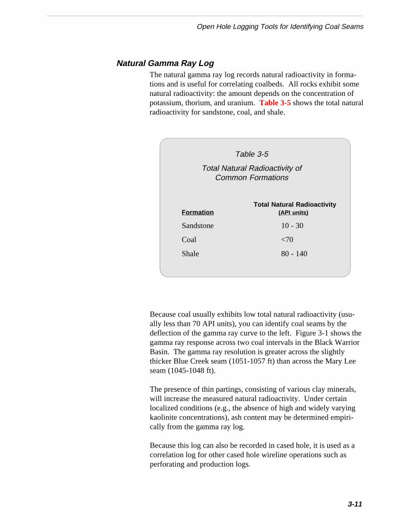
-ef
l
therior
e
s,
gi-
s a
Open Hole Logging Tools for Identifying Coal Seams
Natural Gamma Ray LogThe natural gamma ray log records natural radioactivity in formations and is useful for correlating coalbeds. All rocks exhibit somnatural radioactivity: the amount depends on the concentration opotassium, thorium, and uranium. Table 3-5 shows the total naturaradioactivity for sandstone, coal, and shale.
Total Natural RadioactivityFormation (API units)
Sandstone 10 - 30
Coal <70
Shale 80 - 140
Because coal usually exhibits low total natural radioactivity (usu-ally less than 70 API units), you can identify coal seams by thedeflection of the gamma ray curve to the left. Figure 3-1 shows gamma ray response across two coal intervals in the Black WarBasin. The gamma ray resolution is greater across the slightlythicker Blue Creek seam (1051-1057 ft) than across the Mary Leseam (1045-1048 ft).
The presence of thin partings, consisting of various clay mineralwill increase the measured natural radioactivity. Under certainlocalized conditions (e.g., the absence of high and widely varyinkaolinite concentrations), ash content may be determined empircally from the gamma ray log.
Because this log can also be recorded in cased hole, it is used acorrelation log for other cased hole wireline operations such asperforating and production logs.
Table 3-5
Total Natural Radioactivity ofCommon Formations
3-11
Chapter 3 Wireline Logging
u-
as-
3-12
Dual Induction/Shallow Induction LogThe dual induction log is a tool that measures the resistivity (orconductivity) of a formation to an electrical current which isinduced into the formation. Coal, limestones, and most low-porosity sandstones in coalbed methane regions are highly resis-tive. Shales, in contrast, are nearly always low in resistivity, andthey therefore show up distinctly on resistivity logs.
You can use the deep induction curve primarily for correlatingcoalbeds. The deep induction shows a very gradual increase inresistivity at coalbed boundaries because of its large vertical resoltion (approximately 6 feet). Because most coals in the BlackWarrior Basin are less than 2 feet thick (the Blue Creek seam isapproximately 5 feet thick), the dual induction log is not widelyused on wells in this basin. Dual induction logs are limited by thinbed effects, borehole washouts, and mud resistivity.
The shallow induction log, which is usually run with the dualinduction log, is a resistivity device that normally shows sharpincreases in resistivity at coalbed boundaries. Because this tool ha resolution of approximately 18 inches, you can use it for measuring the thickness of coalbeds.
When using the dual induction log, you should follow these guide-lines:
■■■■■ Use the shallow curve to measure coal thickness.Sometimes you will be able to identify partings, or shale string-ers, of one foot or greater in the coalbed to help you measurethe thickness of the coal.
■■■■■ Use the shallow resistivity curve to read resistivity in thecoalbed.Because of bed thickness effects on deep induction measure-ment, the shallow resistivity curve of the tool usually gives amore accurate measure of resistivity in the coalbed.
Figure 3-3 shows a dual induction/shallow induction log run on awell at the Rock Creek project.
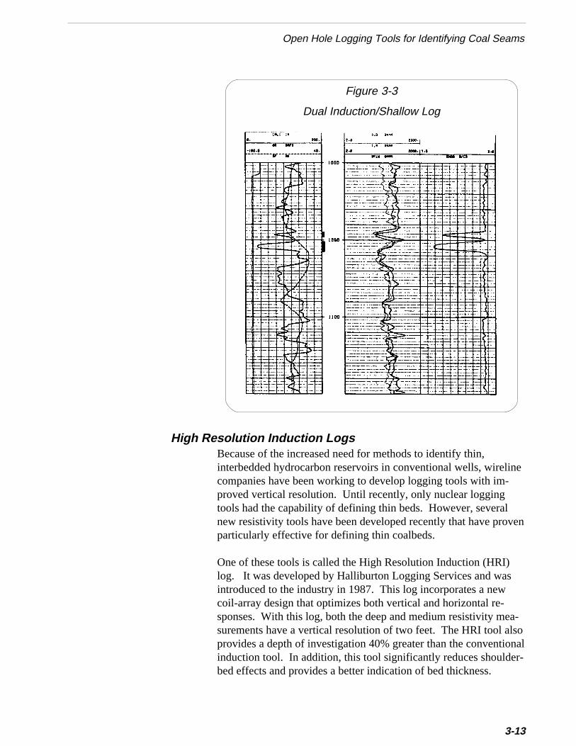
Open Hole Logging Tools for Identifying Coal Seams
Figure 3-3
Dual Induction/Shallow Log
en
-oal
Because of the increased need for methods to identify thin,interbedded hydrocarbon reservoirs in conventional wells, wirelinecompanies have been working to develop logging tools with im-proved vertical resolution. Until recently, only nuclear loggingtools had the capability of defining thin beds. However, severalnew resistivity tools have been developed recently that have provparticularly effective for defining thin coalbeds.
One of these tools is called the High Resolution Induction (HRI)log. It was developed by Halliburton Logging Services and wasintroduced to the industry in 1987. This log incorporates a newcoil-array design that optimizes both vertical and horizontal re-sponses. With this log, both the deep and medium resistivity measurements have a vertical resolution of two feet. The HRI tool alsprovides a depth of investigation 40% greater than the conventioninduction tool. In addition, this tool significantly reduces shoulder-bed effects and provides a better indication of bed thickness.
High Resolution Induction Logs
3-13
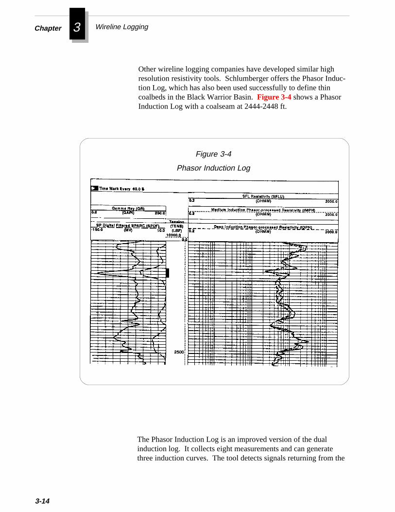
Chapter 3 Wireline Logging
3-14
uc-
Other wireline logging companies have developed similar highresolution resistivity tools. Schlumberger offers the Phasor Indtion Log, which has also been used successfully to define thincoalbeds in the Black Warrior Basin. Figure 3-4 shows a PhasorInduction Log with a coalseam at 2444-2448 ft.he
Figure 3-4
Phasor Induction Log
The Phasor Induction Log is an improved version of the dualinduction log. It collects eight measurements and can generatethree induction curves. The tool detects signals returning from t

Open Hole Logging Tools for Determining the Quality and Properties of Coal
icu-ch
he
tion
anas
.
s,ck
formation that previously were unused by the dual induction log(i.e., signals that are out of phase, or that do not return perpendlarly). The tool uses these out-of-phase signals to display a musharper bed boundary. The Phasor Induction Log has a normalresolution of three feet. Like the dual induction log, this tooldisplays deep, medium, and shallow curves. The resolution of ttool may be enhanced to two feet by computer processing theshallow and medium curves.
The most recent advance in the induction log is the Array InducTool (AIT). This Schlumberger log, which is an improvementover the Phasor Induction Log, collects 28 measurements and cdisplay five induction curves. This tool can investigate as deep 90 inches and as shallow as 10 inches. The AIT provides evenbetter definition of shoulder beds than the Phasor Induction Log
The AIT has only been available to the industry for a few monthand it has not yet been used in coalbed methane wells in the BlaWarrior Basin.
s-
,
Because each type of formation has a characteristic (but not necesarily unique) log response, it is possible not only to identifyspecific formations, but also to assess their quality. Logs havebeen used to estimate reservoir quality in conventional wells formany years. Based on these same principles, logs are now beingused to evaluate the quality and mechanical properties of coalseams. Table 3-6 shows typical log responses in sandstone, shaleand coal for the logs most commonly used to evaluate coals:Density, Gamma Ray, Neutron, and Sonic.
Open Hole Logging Tools for Determining the Quality andProperties of Coal
3-15
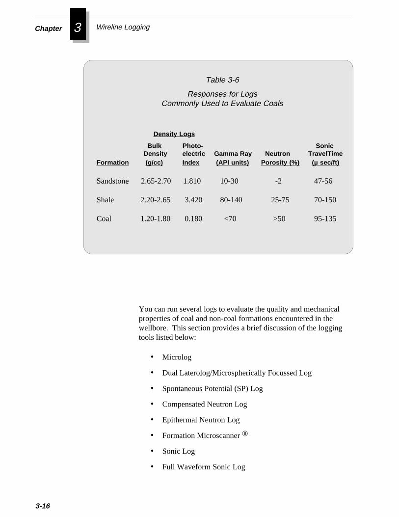
Chapter 3 Wireline Logging
3-16
Table 3-6
Responses for LogsCommonly Used to Evaluate Coals
You can run several logs to evaluate the quality and mechanicalproperties of coal and non-coal formations encountered in thewellbore. This section provides a brief discussion of the loggingtools listed below:
• Microlog
• Dual Laterolog/Microspherically Focussed Log
• Spontaneous Potential (SP) Log
• Compensated Neutron Log
• Epithermal Neutron Log
• Formation Microscanner ®
• Sonic Log
• Full Waveform Sonic Log
Bulk Photo- SonicDensity electric Gamma Ray Neutron TravelTime
Formation (g/cc) Index (API units) Porosity (%) (µ sec/ft)
Sandstone 2.65-2.70 1.810 10-30 -2 47-56
Shale 2.20-2.65 3.420 80-140 25-75 70-150
Coal 1.20-1.80 0.180 <70 >50 95-135
Density Logs
Open Hole Logging Tools for Determining the Quality and Properties of Coal
• Geochemical Logs
• Carbon/Oxygen Log
• Spectral Gamma Ray Log
• Borehole Televiewer
• Temperature Log
• Computer-Processed Log Presentations
• Geophysical Well Log Models
MicrologThe microlog is a tool that measures resistivities at two differentdepths in the formation immediately adjacent to the borehole. Oneof the resistivities is the mudcake resistivity and the other is theformation (or coal) resistivity. The resistivity of the mudcake issignificantly less than that of coal. Consequently, if mudcake hasformed in the borehole across an interval, the two resistivity curveswill separate because they are reading different levels of resistivity.
For mudcake to form, mud filtrate (liquid) must pass into theformation. Thus, the presence of mudcake across a formation is anindication of permeability in that formation. Therefore, positiveseparation of the resistivity curves on a microlog could indicatecoal cleat development in coalbed wells drilled with mud.
Because most wells in the Black Warrior Basin are drilled with airor water instead of mud, the microlog is not usually run in thisbasin. In areas where coalbed methane wells are drilled with mud,there are several factors that can affect the microlog:
❖ Resistivity of the mud
❖ Mudcake thickness
❖ Depth of invasion
❖ Borehole rugosity
❖ Formation porosity
3-17
Chapter 3 Wireline Logging
f the
-
es.u-
e
D
3-18
The resistivity of the mud compresses or expands the micrologresistivity values. In low-resistivity muds, the microlog resistivitiesare compressed to a narrow range, which reduces the accuracy omicrolog ratio. In high-resistivity muds, the microlog resistivitiesare expanded, which enhances the accuracy of the microlog ratiointerpretation. An optimum mud resistivity at bottomhole temperature is normally from 1 to 3 ohm-meters.
Mudcake thickness controls the amount of separation between thenormal and lateral curves. In general, the positive separation yousee on the log increases as the thickness of the mudcake increasThis separation may indicate fluid filtration into the formation. Yocan qualitatively assess the permeability (and hence cleat development) of the coal by comparing the microlog separation across thcoals to that across adjacent formations.
The dual laterolog/microspherically-focused log (DLL/MSFL) is aresistivity tool run primarily in coalbed wells drilled with a saltymud system. Most DLL/MSFL tools are run in wells drilled with amud salinity of 50,000 ppm NaCl. Typically, the DLL/MSFL isused in these mud-drilled wells to calculate porosity.
The microlog is a pad device and is sensitive to rapid changes inthe borehole wall. In washed out boreholes, the microlog oftenmeasures the resistivity of the mud. Therefore, you should runthe log down the hole, with the tool closed, over the bottom1,000 feet of hole to record a log of the mud resistivity. The logof mud resistivity will highlight any changes in mud resistivityover the zone of interest and help ensure that you use thecorrect value of Rm when interpreting the log.
Some drilling mud additives used as flocculants can causeerroneous microlog interpretations. These flocculants, whichplate boreholes with mudcake, may cause the microlog to showpositive separation in low permeability coalbeds.
Very heavy or viscous muds may also cause erroneously highestimates of coal cleating. You should closely monitor andcontrol fluid loss while drilling the hole. Fluid loss of the mudsystem controls mudcake thickness.
ual Laterolog/Microspherically Focussed Log
❈❈❈❈❈ Important
❈❈❈❈❈ Important
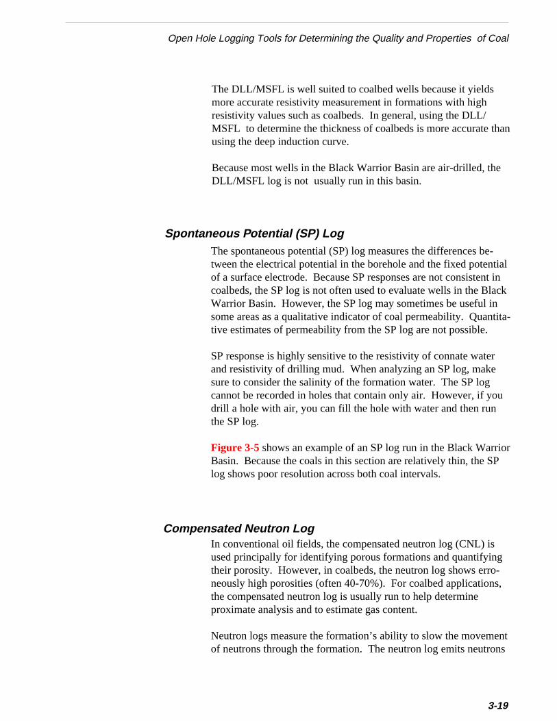
an
l ink
a-
Open Hole Logging Tools for Determining the Quality and Properties of Coal
The DLL/MSFL is well suited to coalbed wells because it yieldsmore accurate resistivity measurement in formations with highresistivity values such as coalbeds. In general, using the DLL/MSFL to determine the thickness of coalbeds is more accurate thusing the deep induction curve.
Because most wells in the Black Warrior Basin are air-drilled, theDLL/MSFL log is not usually run in this basin.
Spontaneous Potential (SP) LogThe spontaneous potential (SP) log measures the differences be-tween the electrical potential in the borehole and the fixed potentiaof a surface electrode. Because SP responses are not consistentcoalbeds, the SP log is not often used to evaluate wells in the BlacWarrior Basin. However, the SP log may sometimes be useful insome areas as a qualitative indicator of coal permeability. Quantittive estimates of permeability from the SP log are not possible.
SP response is highly sensitive to the resistivity of connate waterand resistivity of drilling mud. When analyzing an SP log, makesure to consider the salinity of the formation water. The SP logcannot be recorded in holes that contain only air. However, if youdrill a hole with air, you can fill the hole with water and then runthe SP log.
Figure 3-5 shows an example of an SP log run in the Black WarriorBasin. Because the coals in this section are relatively thin, the SPlog shows poor resolution across both coal intervals.
Compensated Neutron LogIn conventional oil fields, the compensated neutron log (CNL) isused principally for identifying porous formations and quantifyingtheir porosity. However, in coalbeds, the neutron log shows erro-neously high porosities (often 40-70%). For coalbed applications,the compensated neutron log is usually run to help determineproximate analysis and to estimate gas content.
Neutron logs measure the formation’s ability to slow the movementof neutrons through the formation. The neutron log emits neutrons
3-19
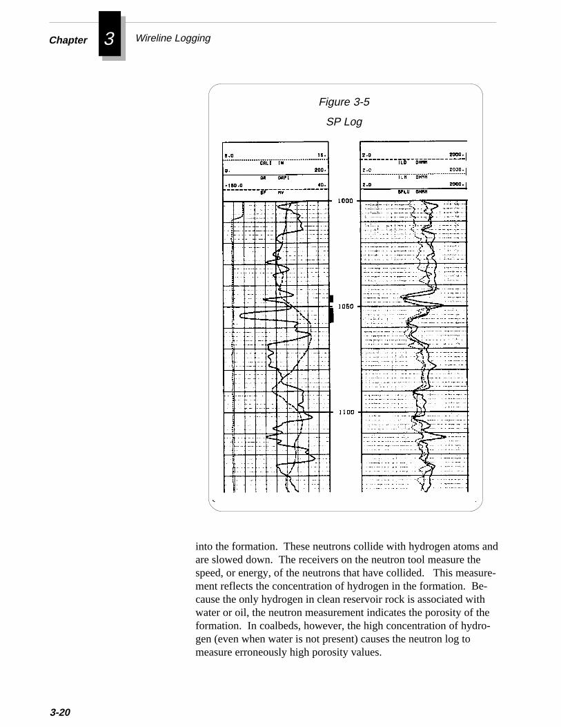
Chapter 3 Wireline Logging
3-20
nd
ure--
e-
Figure 3-5
SP Log
into the formation. These neutrons collide with hydrogen atoms aare slowed down. The receivers on the neutron tool measure thespeed, or energy, of the neutrons that have collided. This measment reflects the concentration of hydrogen in the formation. Because the only hydrogen in clean reservoir rock is associated withwater or oil, the neutron measurement indicates the porosity of thformation. In coalbeds, however, the high concentration of hydrogen (even when water is not present) causes the neutron log tomeasure erroneously high porosity values.
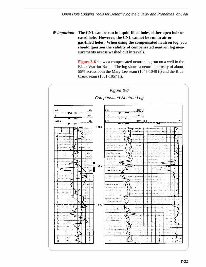
u
Open Hole Logging Tools for Determining the Quality and Properties of Coal
The CNL can be run in liquid-filled holes, either open hole orcased hole. However, the CNL cannot be run in air orgas-filled holes. When using the compensated neutron log, yoshould question the validity of compensated neutron log mea-surements across washed out intervals.
❈❈❈❈❈ Important
theutlue
Figure 3-6 shows a compensated neutron log run on a well inBlack Warrior Basin. The log shows a neutron porosity of abo55% across both the Mary Lee seam (1045-1048 ft) and the BCreek seam (1051-1057 ft).
3-21
Figure 3-6
Compensated Neutron Log

Chapter 3 Wireline Logging
-ne
werh
u-
.
te
3-22
The Formation Microscanner (a registered trademark ofSchlumberger) is a pad device that records microresistivity variations around the borehole wall. The tool can be used to determicoal cleat orientation.
Formation MicroScanner®
Epithermal Neutron LogNeutron logs emit high energy neutrons into the formation. Asthese neutrons collide with the formation they are slowed to a loenergy level, or thermal state. The neutrons that remain at a higenergy level are called epithermal neutrons.
The compensated neutron log (CNL) can detect only thermal netrons. However, the epithermal neutron log contains detectorswhich can distinguish between thermal and epithermal neutronsBoth the CNL and epithermal logs are useful for identifyingcoalbeds. However, the epithermal log can provide more accuraporosity measurements in non-coal formations. In addition, theepithermal log can be run in both open and cased holes.
ee
d
Formation MicroScanner® data from the Rock Creek Project in thBlack Warrior Basin were successfully analyzed to determine thorientation of coal cleat. Measurements from the FormationMicroScanner agreed favorably with cleat orientations determinefrom whole core data recovered from several wells. Figure 3-7compares the Rose Diagrams determined from a FormationMicroScanner® log and from cores for a well in the Black WarriorBasin. Rose Diagrams show the orientation of coal cleat.
s
o
act-
Open Hole Logging Tools for Determining the Quality and Properties of Coal
Figure 3-7
Comparison of Cleat Orientation Determined froma Formation MicroScanner® Log and from Cores
Cleats were identified as small conductive breaks on opposingresistivity pad images that were enhanced. Cleat orientation wadetermined by selecting points on the resistivity images at theconductive breaks. An equidistant midpoint was also selected sthat a plane defining cleat azimuth could be defined by the com-puter. Then, the cleat strike was determined by adding or subtring ninety degrees to or from the computed azimuth.
3-23
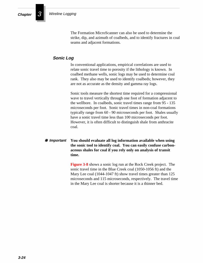
Chapter 3 Wireline Logging
al
l
3-24
The Formation MicroScanner can also be used to determine thestrike, dip, and azimuth of coalbeds, and to identify fractures in coseams and adjacent formations.
In conventional applications, empirical correlations are used torelate sonic travel time to porosity if the lithology is known. Incoalbed methane wells, sonic logs may be used to determine coalrank. They also may be used to identify coalbeds; however, theyare not as accurate as the density and gamma ray logs.
Sonic tools measure the shortest time required for a compressionawave to travel vertically through one foot of formation adjacent tothe wellbore. In coalbeds, sonic travel times range from 95 - 135microseconds per foot. Sonic travel times in non-coal formationstypically range from 60 - 90 microseconds per foot. Shales usuallyhave a sonic travel time less than 100 microseconds per foot.However, it is often difficult to distinguish shale from anthracitecoal.
Sonic Log
You should evaluate all log information available when usingthe sonic tool to identify coal. You can easily confuse carbon-aceous shales for coal if you rely only on analysis of transittime.
❈❈❈❈❈ Important
e
Figure 3-8 shows a sonic log run at the Rock Creek project. Thesonic travel time in the Blue Creek coal (1050-1056 ft) and theMary Lee coal (1044-1047 ft) show travel times greater than 125microseconds and 115 microseconds, respectively. The travel timin the Mary Lee coal is shorter because it is a thinner bed.

s
at hasions to
Open Hole Logging Tools for Determining the Quality and Properties of Coal
Figure 3-8
Sonic Log
For many years, the only information used from the sonic log wathe first wave arrival (the compressional wave). However, eachpulse from the transmitter of a sonic log creates several types ofwaves in the formation. Because it has long been recognized ththese waves would change forms at bed boundaries, much workbeen done to understand and correlate the waveforms to formatcharacteristics. This work first led to the development of method
Full Waveform Sonic Log
3-25
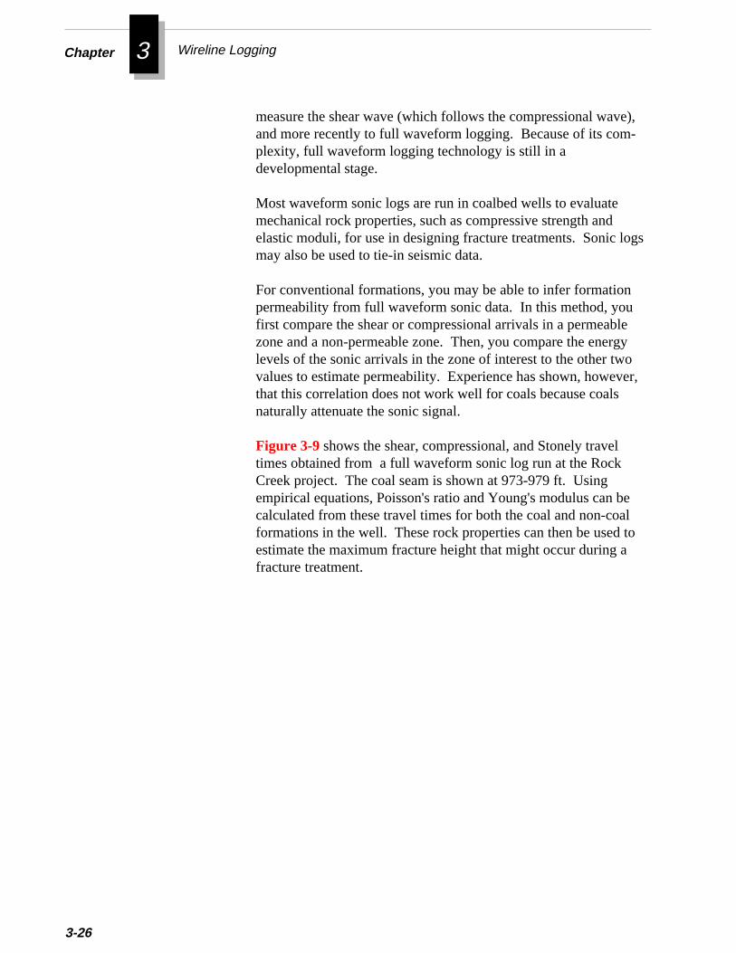
Chapter 3 Wireline Logging
),
gs
y
r,
3-26
measure the shear wave (which follows the compressional waveand more recently to full waveform logging. Because of its com-plexity, full waveform logging technology is still in adevelopmental stage.
Most waveform sonic logs are run in coalbed wells to evaluatemechanical rock properties, such as compressive strength andelastic moduli, for use in designing fracture treatments. Sonic lomay also be used to tie-in seismic data.
For conventional formations, you may be able to infer formationpermeability from full waveform sonic data. In this method, youfirst compare the shear or compressional arrivals in a permeablezone and a non-permeable zone. Then, you compare the energlevels of the sonic arrivals in the zone of interest to the other twovalues to estimate permeability. Experience has shown, howevethat this correlation does not work well for coals because coalsnaturally attenuate the sonic signal.
elto
Figure 3-9 shows the shear, compressional, and Stonely traveltimes obtained from a full waveform sonic log run at the RockCreek project. The coal seam is shown at 973-979 ft. Usingempirical equations, Poisson's ratio and Young's modulus can bcalculated from these travel times for both the coal and non-coaformations in the well. These rock properties can then be used estimate the maximum fracture height that might occur during afracture treatment.
Open Hole Logging Tools for Determining the Quality and Properties of Coal
Figure 3-9
Full Waveform Sonic Log
of
,I
Geochemical logs are useful in measuring elemental componentsthe formation. These logs can be used in creating depositionalmodels for coalbeds and in correlating ash beds from well-to-wellsimilar to the use of the spectral gamma ray tools. Currently, GRis sponsoring research on developing depositional models forcoalbeds based on geochemical logging.
Geochemical Logs
3-27
Chapter 3 Wireline Logging
anol.
. you
3-28
A typical geochemical string includes a natural gamma ray tool, aluminum activation clay tool, and a gamma ray spectroscopy toThe combination of these tools can measure up to 10 elementalconcentrations in the formation. You can use these elementalconcentrations together with data from the density, neutron, andspectral density tools to detect the presence of up to 10 mineralsGeochemical logs are most accurate when run in open hole, butcan also run them in cased holes.
Two methods are currently used to convert the elemental data tomineral data. You can calibrate the logging tool by using a database containing core measurements from around the world. Oralternatively, you can calibrate the tool with local core data mea-surements.
uch
i-yuc-unt
e)l
The geochemical log and the carbon/oxygen log are often runtogether and displayed on a computer-processed presentation sas the one shown in Figure 3-10 from the Rock Creek project. Theright hand track of this presentation shows the formation compostion derived by a computer model from the base logs (gamma raspectroscopy, natural gamma ray, neutron, density, and dual indtion). Because early lithology models could not adequately accofor coal intervals, this log erroneously shows a quartz (sandstonformation with high porosity across the Mary Lee/Blue Creek coaseam at 1044-1056 ft.
,ry
Most logging companies now have computer-processed lithologymodels that can accurately identify coal seams. For example,Figure 3-11 shows a Schlumberger VOLAN® geochemical log runin the same Rock Creek well. The VOLAN® log, which is derivedfrom the base logs (gamma ray spectroscopy, natural gamma rayneutron, density, and dual induction), accurately identifies the MaLee/Blue Creek coal seam at 1045-1058 ft.
f
deee.
The carbon/oxygen log provides a measure of the carbon content othe formation. In conventional oil and gas applications, the carbon/oxygen (C/O) log is used to help determine oil saturation behindpipe. In coalbed methane wells, the carbon/oxygen log may be useto determine the BTU content of coal. Bituminous coal yields a largcontrast between the carbon/oxygen ratio at the sand-shale baselinand in the coal. This contrast can help you identify coals behind pip
Carbon/Oxygen Log
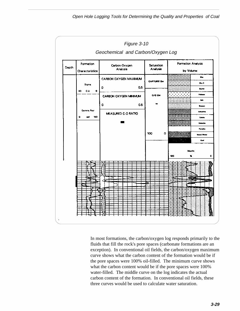
Open Hole Logging Tools for Determining the Quality and Properties of Coal
thenumifs
Figure 3-10
Geochemical and Carbon/Oxygen Log
In most formations, the carbon/oxygen log responds primarily tofluids that fill the rock's pore spaces (carbonate formations are aexception). In conventional oil fields, the carbon/oxygen maximcurve shows what the carbon content of the formation would be the pore spaces were 100% oil-filled. The minimum curve showwhat the carbon content would be if the pore spaces were 100%water-filled. The middle curve on the log indicates the actualcarbon content of the formation. In conventional oil fields, thesethree curves would be used to calculate water saturation.
3-29
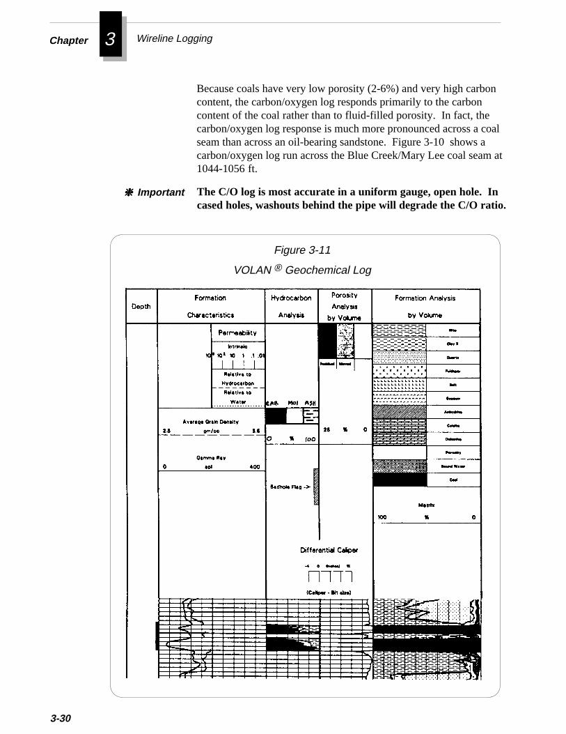
Chapter 3 Wireline Logging
al
t
3-30
Because coals have very low porosity (2-6%) and very high carboncontent, the carbon/oxygen log responds primarily to the carboncontent of the coal rather than to fluid-filled porosity. In fact, thecarbon/oxygen log response is much more pronounced across a coseam than across an oil-bearing sandstone. Figure 3-10 shows acarbon/oxygen log run across the Blue Creek/Mary Lee coal seam a1044-1056 ft.
The C/O log is most accurate in a uniform gauge, open hole. Incased holes, washouts behind the pipe will degrade the C/O ratio.
❈❈❈❈❈ Important
Figure 3-11
VOLAN ® Geochemical Log
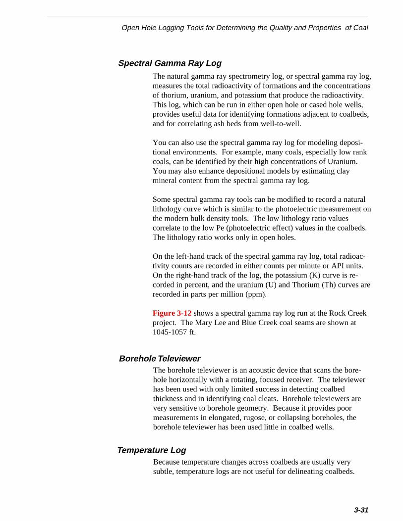
og,ns
,
k
aln
.
-
re
Open Hole Logging Tools for Determining the Quality and Properties of Coal
Spectral Gamma Ray LogThe natural gamma ray spectrometry log, or spectral gamma ray lmeasures the total radioactivity of formations and the concentratioof thorium, uranium, and potassium that produce the radioactivity.This log, which can be run in either open hole or cased hole wells,provides useful data for identifying formations adjacent to coalbedsand for correlating ash beds from well-to-well.
You can also use the spectral gamma ray log for modeling deposi-tional environments. For example, many coals, especially low rancoals, can be identified by their high concentrations of Uranium.You may also enhance depositional models by estimating claymineral content from the spectral gamma ray log.
Some spectral gamma ray tools can be modified to record a naturlithology curve which is similar to the photoelectric measurement othe modern bulk density tools. The low lithology ratio valuescorrelate to the low Pe (photoelectric effect) values in the coalbedsThe lithology ratio works only in open holes.
On the left-hand track of the spectral gamma ray log, total radioactivity counts are recorded in either counts per minute or API units.On the right-hand track of the log, the potassium (K) curve is re-corded in percent, and the uranium (U) and Thorium (Th) curves arecorded in parts per million (ppm).
Figure 3-12 shows a spectral gamma ray log run at the Rock Creekproject. The Mary Lee and Blue Creek coal seams are shown at1045-1057 ft.
Borehole TeleviewerThe borehole televiewer is an acoustic device that scans the bore-hole horizontally with a rotating, focused receiver. The televiewerhas been used with only limited success in detecting coalbedthickness and in identifying coal cleats. Borehole televiewers arevery sensitive to borehole geometry. Because it provides poormeasurements in elongated, rugose, or collapsing boreholes, theborehole televiewer has been used little in coalbed wells.
Because temperature changes across coalbeds are usually verysubtle, temperature logs are not useful for delineating coalbeds.
Temperature Log
3-31
Chapter 3 Wireline Logging
3-32
However, you can use a temperature log to locate water-producingzones, points of gas entry into the wellbore encountered duringdrilling, which may have to be cased off before completing the well.
en-
mma
Figure 3-12
Spectral Gamma Ray Log
Computer-Processed Log PresentationsMany of the logging service companies offer customized log prestations that may help you identify coals and evaluate their qualityand producibility. These logs contain computer-processed databased on the responses of the basic logs, such as the density, ga

r.
,
,
Open Hole Logging Tools for Determining the Quality and Properties of Coal
ray, resistivity, sonic, and neutron logs. Some of the computer-processed logs also incorporate core data provided by the operato
Because the basic logs have better resolution in thicker formationsthe accuracy of computer-processed logs is likewise greater inthick formations, such as those in the San Juan Basin, than it is inthin formations, such as those in the Black Warrior Basin.
Though computer-processed logs may prove useful, if you decideto use them, make sure you fully understand what log data is usedto generate the presentation and how that data is processed. Thevalue of the computer-processed presentation will be no greaterthan the quality of the data used to create it.
The computer-processed geochemical log shown earlier in Figure3-10 is based on the gamma ray spectroscopy, natural gamma rayneutron, bulk density, and dual induction logs. This geochemicallog shows the formation composition of all intervals.
tingell
b-el-e
resr
on
in
Estimating coal quality, gas content, and coal permeability fromopen hole logs certainly is not a proven technique. However,research is underway to develop methods for accurately correlaopen hole logs to core data so that the coals in a development wcan be evaluated with open hole logs alone.
When a correlation between the core and log data has been estalished for one well, a model based on that correlation can be devoped for the entire field. The model can then be used to estimatcoal quality, gas content, and coal permeability for developmentwells in that field based solely on well log information. Thistechnique, when perfected, could eliminate the need to obtain cofrom each well. For more information on this GRI research, refeto The Development of Formation Evaluation Technology forCoalbed Methane - Annual Technical Report (December 1990 -December 1991), ResTech, Inc. for GRI, March, 1992.
Geophysical Well Log Models
Figure 3-13 shows a computer-processed coal quality log basedthe sonic and bulk density logs. This log graphically shows thepercentage composition of carbon, ash, volatiles, and moisturethe Upper Pratt "A" and Upper Pratt "B" coal seams.
3-33

Chapter 3 Wireline Logging
acheamhe
ty.canhate of
in
3-34
Figure 3-13
Computer-Processed Coal Quality Log
If you use geophysical modelling for a field, you should model ecoal seam separately. Don't assume correlations for one coal swill apply to another seam. In addition, you should understand tgeology of the field well enough to recognize what factors mightcause a variation in coal quality, gas content, or coal permeabiliThe reservoir and rock properties of the coal and overlying rock vary considerably over short distances. Some of the variables tmay contribute to this heterogeneity are the presence or absencfractures in the overlying rock, stress regimes in the rock, cleatdevelopment within the coal, and the presence of mineral filling the cleat system.
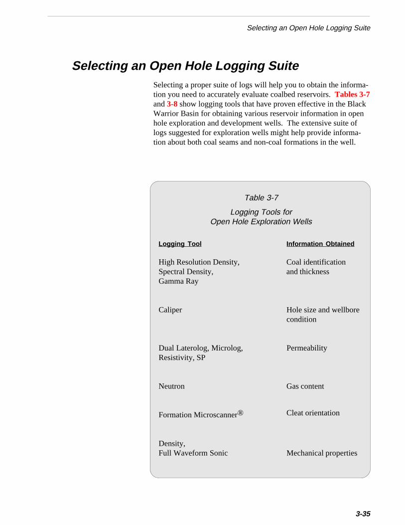
a-
cknf-.
Selecting an Open Hole Logging Suite
Selecting an Open Hole Logging SuiteSelecting a proper suite of logs will help you to obtain the informtion you need to accurately evaluate coalbed reservoirs. Tables 3-7and 3-8 show logging tools that have proven effective in the BlaWarrior Basin for obtaining various reservoir information in opehole exploration and development wells. The extensive suite ologs suggested for exploration wells might help provide information about both coal seams and non-coal formations in the well
Table 3-7
Logging Tools forOpen Hole Exploration Wells
Logging Tool Information Obtained
High Resolution Density, Coal identificationSpectral Density, and thicknessGamma Ray
Caliper Hole size and wellborecondition
Dual Laterolog, Microlog, PermeabilityResistivity, SP
Neutron Gas content
Formation Microscanner® Cleat orientation
Density,Full Waveform Sonic Mechanical properties
3-35
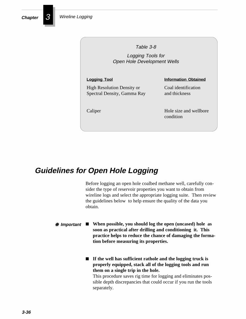
Chapter 3 Wireline Logging
-
-
ew
3-36
Logging Tool Information Obtained
High Resolution Density or Coal identificationSpectral Density, Gamma Ray and thickness
Caliper Hole size and wellborecondition
■ When possible, you should log the open (uncased) hole assoon as practical after drilling and conditioning it. Thispractice helps to reduce the chance of damaging the forma-tion before measuring its properties.
■ If the well has sufficient rathole and the logging truck isproperly equipped, stack all of the logging tools and runthem on a single trip in the hole.This procedure saves rig time for logging and eliminates possible depth discrepancies that could occur if you run the toolsseparately.
Before logging an open hole coalbed methane well, carefully consider the type of reservoir properties you want to obtain fromwireline logs and select the appropriate logging suite. Then revithe guidelines below to help ensure the quality of the data youobtain.
Guidelines for Open Hole Logging
Table 3-8
Logging Tools forOpen Hole Development Wells
❈❈❈❈❈ Important
es,
l
th-
n
Cased Hole Logging Tools
Cased Hole Logging ToolsTo obtain the most accurate measurements of formation propertiyou should log the open (uncased) hole. However, if hole condi-tions or other constraints prevent you from running an open holelog, you may still obtain some formation data by running a casedhole log. You may also run cased hole logs during the producinglife of a well to monitor reservoir properties, to evaluate additionacoal seams, or to diagnose mechanical wellbore problems. Thissection describes tools you can use to log cased hole coalbed meane wells.
■ If you are logging in a new area, you can refer to well logsfrom offset wells (if they are available) to approximate coalseam depths.
■ Make one or two repeat runs over the coal beds beforemaking the main logging run.Repeat runs help you to validate the logging measurement.
■ When running nuclear logging tools, use a logging speed of30 feet/minute.
■ Make one logging pass at 18 feet/minute using high resolu-tion processing to record maximum detail in the coalbeds.Shale stringers in coalbeds may be masked because they arethinner than the standard vertical resolution. High resolutionprocessing of the density log can reduce the vertical resolutioto six inches. You may be able to accurately identify shalestringers six inches thick, but you still may not be able to identify thinner stringers.
■ High-resolution processing must be done when you origi-nally log the well. It is not possible to re-process a logrecorded with a two-foot resolution to change its resolutionto one foot.
■ To obtain greater detail from logs, you can present them onan expanded scale, (e.g., 20 inches equal to 100 feet).
❈❈❈❈❈ Important
3-37
Chapter 3 Wireline Logging
d
ds
ept
ty,venn-er
3-38
The dual detector-compensated neutron log is the tool most fre-quently run in cased holes to identify coalbeds and to measure netcoal thickness. The measurements from a cased hole compensateneutron log should be as reliable as those obtained from an openhole compensated neutron log.
The gamma ray log records the natural radioactivity of formations.Because coal usually exhibits low total natural radioactivity (usu-ally less than 70 API units), you can identify coal seams by thedeflection of the gamma ray curve to the left. The presence of thinpartings, consisting of various clay minerals, will increase themeasured natural radioactivity.
Washouts behind pipe can be difficult to interpret with acompensated neutron tool.
❈❈❈❈❈ Important
The pulsed neutron log is often run in cased holes to identify coalbeand to measure net coal thickness. The pulsed neutron log is inter-preted in much the same way as the compensated neutron log, excthat pulsed neutron log displays a neutron ratio instead of a neutronporosity. Increasing neutron ratio corresponds to increasing porosiwhich is indicative of coal. The neutron ratio curve is not as sensitias the compensated neutron porosity. However, the pulsed neutrolog may have a slightly better depth of investigation than the compesated neutron log. Therefore, the pulsed neutron log may give bettresolution in cased hole than the compensated neutron log.
These general guidelines apply to the pulsed neutron log:
■ The pulsed neutron log is ineffective when it encountershole washouts behind pipe.
■ You should establish the pulsed neutron ratio cutoff for coalon a well-by-well basis.Differences in hole size, cement quality, casing size, and tubingsize affect the accuracy of the ratio curve.
Compensated Neutron Log
Pulsed Neutron Log
Gamma Ray Log
bs.
off
Cased Hole Logging Tools
Because the gamma ray log can be recorded in cased holes, it isvery useful for:
❖ Correlating coalbeds
❖ Providing accurate depth control when it is run with acasing collar locator
❖ Locating radioactive tracers used in fracturing treatments(If more than one isotope is used, you should use the spec-tral gamma ray log)
Cement Bond/Variable Density LogCement evaluation tools that employ acoustic measurements, ifcorrectly interpreted, can provide useful information for evaluatingthe success of primary cementing on initial well completions.They can also be used to assess the need for remedial cement jo
The cement bond log (CBL) provides a continuous measurement the amplitudes of sound pulses after they have traveled a length ocasing. This amplitude is maximum in unsupported pipe, andminimum in well-cemented casing.
The variable density log (VDL) is usually included with the CBL.The VDL provides information about the quality of the formationbonding. You can run a gamma ray log simultaneously with theCBL/VDL.
The primary uses for the CBL/VDL are:
❖ To determine the effectiveness of the cement sheath in thecasing-formation annulus
❖ To check the effectiveness of squeeze cementing
❖ To locate the cement top
An improved version of the standard cement bond log is nowavailable. This log can help you evaluate the distribution andquality of cement around the entire wellbore radius. The tool isuseful for identifying channels that cannot be detected by standard
3-39
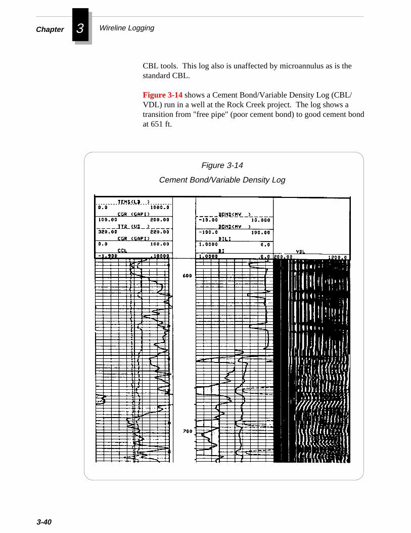
Chapter 3 Wireline Logging
d
3-40
CBL tools. This log also is unaffected by microannulus as is thestandard CBL.
Figure 3-14 shows a Cement Bond/Variable Density Log (CBL/VDL) run in a well at the Rock Creek project. The log shows atransition from "free pipe" (poor cement bond) to good cement bonat 651 ft.
Figure 3-14
Cement Bond/Variable Density Log
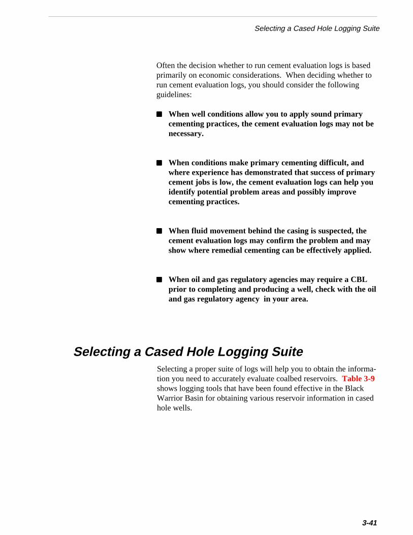
do
a-
d
Selecting a Cased Hole Logging Suite
Often the decision whether to run cement evaluation logs is baseprimarily on economic considerations. When deciding whether trun cement evaluation logs, you should consider the followingguidelines:
■■■■■ When well conditions allow you to apply sound primarycementing practices, the cement evaluation logs may not benecessary.
■■■■■ When conditions make primary cementing difficult, andwhere experience has demonstrated that success of primarycement jobs is low, the cement evaluation logs can help youidentify potential problem areas and possibly improvecementing practices.
■■■■■ When fluid movement behind the casing is suspected, thecement evaluation logs may confirm the problem and mayshow where remedial cementing can be effectively applied.
■■■■■ When oil and gas regulatory agencies may require a CBLprior to completing and producing a well, check with the oiland gas regulatory agency in your area.
Selecting a proper suite of logs will help you to obtain the informtion you need to accurately evaluate coalbed reservoirs. Table 3-9shows logging tools that have been found effective in the BlackWarrior Basin for obtaining various reservoir information in casehole wells.
Selecting a Cased Hole Logging Suite
3-41
Chapter 3 Wireline Logging
d.
idergses
.
e-w
t,
t
3-42
Table 3-9
Logging Tools for Cased Hole Wells
Logging Tool Information Obtained
Mineral logging density* Coalbed identificationand seam thickness
Gamma ray/CCL Coalbed correlation
Cement bond log/VDL/CCL Integrity of cementjob
* Not necessary if an adequate open hole density log was obtaine
Guidelines for Cased Hole LoggingBefore logging a cased hole coalbed methane well, carefully consthe type of reservoir properties you want to obtain from wireline loand select the appropriate logging suite. Then review the guidelinbelow to help ensure the quality of the data you obtain.
■■■■■ Before beginning any wireline completions or workoveroperations, always compare the depths on the cased holegamma ray log to the depths on the open hole gamma ray log
For example, when preparing to perforate an interval, neverassume the cased hole gamma ray log has been properly corrlated to the open hole gamma ray log. The perforations for newells or recompletions are often selected from the open holelog. If you assume the cased hole log is on depth, and it is noyou could perforate the wrong interval. Always verify whichlog the perforations were selected from, and then correlate thalog with the cased hole log.
s
Guidelines for Cased HoleLogging
■■■■■ When running a cased hole log on a workover, alwaysidentify the static fluid level in the wellbore.Knowing the static fluid level can help with later log interpreta-tion.
■■■■■ When running a cement bond log, make sure you includethe logs or displays listed below.You can use the amplitude curve and variable density curve toevaluate the cement job.
❖ Amplitude curve for cement
❖ Variable density display
❖ Casing collar locator
❖ Gamma ray log
■■■■■ Avoid circulating cold fluids in the casing before runningthe initial cement bond log.Cold fluids could adversely affect the amplitude and VDLmeasurements on the cement bond log.
■■■■■ Correlate the cement bond log with the open hole log tomake sure they are recorded at the same depth. Thegamma ray log is the primary source for this correlation.
■■■■■ When running a cement bond log, make sure you tag andrecord the plugged back total depth (PBTD) of the well andlog from PBTD to the top of the cement.
■■■■■ If the cement bond log shows poor cement bond throughoutthe hole or through a large section, pressure up on thecasing and rerun the log under pressure.A microannulus between the casing and cement can cause thecement bond log to show poor bonding. Pressuring up on thecasing expands the casing, which can reduce the microannuluand improve the cement bond.
3-43
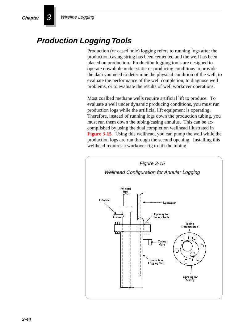
Chapter 3 Wireline Logging
en
, toll
n
u
3-44
Production Logging ToolsProduction (or cased hole) logging refers to running logs after theproduction casing string has been cemented and the well has beplaced on production. Production logging tools are designed tooperate downhole under static or producing conditions to providethe data you need to determine the physical condition of the wellevaluate the performance of the well completion, to diagnose weproblems, or to evaluate the results of well workover operations.
Most coalbed methane wells require artificial lift to produce. Toevaluate a well under dynamic producing conditions, you must ruproduction logs while the artificial lift equipment is operating.Therefore, instead of running logs down the production tubing, yomust run them down the tubing/casing annulus. This can be ac-complished by using the dual completion wellhead illustrated in
ehis
Figure 3-15. Using this wellhead, you can pump the well while thproduction logs are run through the second opening. Installing twellhead requires a workover rig to lift the tubing.
Figure 3-15
Wellhead Configuration for Annular Logging

ane
Production Logging Tools
The most common production logging tools used in coalbed methwells are:
• Continuous Flowmeter
• Gradiomanometer
• Temperature Log
• Downhole Camera
Continuous Flowmeter
The continuous flowmeter is used to determine which coal inter-vals are contributing flow to the wellbore and the percentage flowcontribution from each interval. The tool is a spinner type veloci-meter which records a continuous flow profile versus depth. Al-though the continuous flowmeter has no practical upper limit onflow rate which can be measured, there is a minimum flow ratebelow which the tool will not operate.
The flowmeters used for most conventional applications requiredminimum flow rates that were higher than many coalbed methanewells could produce. To reduce the required minimum flow rate,Computalog Wireline Services developed a flowmeter with a
-
e.
lighter (titanium) impeller and improved bearings. This flowmetertool, illustrated in Figure 3-16, is being used successfully oncoalbed methane wells in the Black Warrior Basin.
Fluid viscosity has a marked effect on spinner speed; decreasedviscosity increases spinner speed. Therefore, the downhole re-sponse curve of spinner speed versus fluid velocity must be established for specific well conditions.
A method of interpretation called the Two-Pass Technique iseffective for multi-phase flow. In its simplest form, this techniqueinvolves making one pass down and one pass up through the zonThe response curves are then matched in the zone of zero flowbelow the bottom perforations. The Two-Pass Technique shouldreduce interpretation time and permit recognition of relativelysmall fluid entries.
3-45
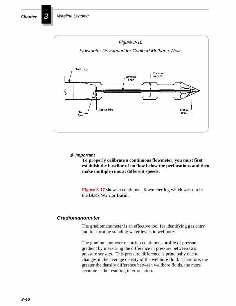
Chapter 3 Wireline Logging
he
3-46
Figure 3-16
Flowmeter Developed for Coalbed Methane Wells
Figure 3-17 shows a continuous flowmeter log which was run inthe Black Warrior Basin .
Gradiomanometer
The gradiomanometer is an effective tool for identifying gas entryand for locating standing water levels in wellbores.
The gradiomanometer records a continuous profile of pressuregradient by measuring the difference in pressure between twopressure sensors. This pressure difference is principally due tochanges in the average density of the wellbore fluid. Therefore, tgreater the density difference between wellbore fluids, the moreaccurate is the resulting interpretation.
To properly calibrate a continuous flowmeter, you must firstestablish the baseline of no flow below the perforations and thenmake multiple runs at different speeds.
❈ ❈ ❈ ❈ ❈ Important
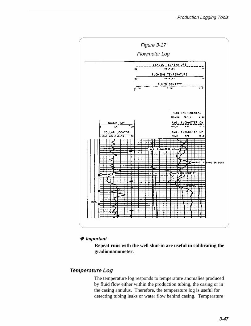
Production Logging Tools
Figure 3-17
Flowmeter Log
The temperature log responds to temperature anomalies producedby fluid flow either within the production tubing, the casing or inthe casing annulus. Therefore, the temperature log is useful fordetecting tubing leaks or water flow behind casing. Temperature
Temperature Log
Repeat runs with the well shut-in are useful in calibrating thegradiomanometer.
❈❈❈❈❈ Important
3-47
Chapter 3 Wireline Logging
3-48
log interpretations can also be used to determine flow rates andpoints of fluid entry into the wellbore.
Downhole CameraThe downhole camera is a specially designed video camera thatallows viewing of actual conditions in the wellbore. Because theresolution of downhole cameras has improved greatly in recentyears, the camera has become an effective tool in diagnosingdownhole production problems in coalbed methane wells. It hasalso helped in evaluating the location and orientation of fractures inopen holes.
Specifically, you can use downhole camera surveys in:
❖ Determining whether perforations are open or plugged withfines or scale
❖ Determining qualitatively which zones are contributing flowand the amount of flow
❖ Determining the type of influx along vertical coal cleats orin bedding planes
❖ Evaluating the condition of casing (e.g., looking for corro-sion or splits)
❖ Inspecting the location and position of a fish left whiledrilling or working over the well
Limitations of the Camera SurveyThough the camera is a useful tool, it does have limitations. Forexample, the hole must contain clear fluid for the camera to providedetailed pictures. If the fluid is not clear, you may try to displace itwith clear fluid. However, the fluid you pump may flow intoshallow perforations or permeable zones. You may find it difficultto displace fluid from deeper intervals without running the tubingback into the well.
Another possible limitation is the pressure rating of the camera.This rating not only limits the maximum depth at which the cameracan be used, but may also limit the operations that can be per-formed with the camera in the hole. Because the camera used at
Production Logging Tools
the Rock Creek Project was rated for 1000 psi, it worked effectivelyfor the shallow zones of the Black Warrior Basin.
Running the Camera SurveyTo get the best information from the camera survey, you shoulddiscuss your objectives for the survey with the camera crew beforethey rig up. Tell them specifically what information you would likefor them to obtain from the survey.
The usual procedure for running a downhole camera survey at theRock Creek Project is listed below:
At least one day before the survey
1. Prepare a list of features you wish to view in the well andtheir depths (if you know them).
2. Schedule the camera unit to be at the well site and ready torun in the hole as soon as the workover rig finishes pullingthe tubing.
3. Schedule a truckload of fresh clear water to remain onstandby at the well site while running the camera survey.
4. Make sure to have a casing collar log on location so you cancorrelate the depth of the camera as you would with anyproduction log.
The day of the survey
1. Mobilize the workover rig.
2. Pull sucker rod string, downhole pump, and tubing stringout of the hole.
3. Rig down the workover rig (unless it is more practical oreconomical to leave it rigged up during the survey).
3-49
Chapter 3 Wireline Logging
3-50
4. Run in the hole with the camera.
5. Proceed downhole as quickly as practical so you can viewthe zone before encroaching water covers it.
6. Correlate the depth of the camera using a previous casingcollar log.The camera survey is not run with a casing collar locator log,but you will be able to identify casing connections with thecamera.
7. Run the camera through the zone of interest and makenotes of any pertinent observations.
8. If the well fluid is too dark to see through, pump thestandby water into the wellbore while the camera isdownhole. Do not exceed a pressure of 1000 psi on thecamera.
9. When finished viewing the wellbore, pull the camera out ofthe hole.
10. Rig up the workover rig and run the tubing string, pump,and rod string back into the well.
❖ ❖ ❖
Additional Resources
Additional Resources
“The Development of Formation Evaluation Technology forCoalbed Methane - Annual Technical Report (December 1990 -December 1991),” ResTech, Inc. (for GRI), March, 1992.
Hilche, D.W., “Advanced Well Log Interpretation,” Douglas W.Hilche, Inc., Golden, Colorado, 1982.
Mullen, M.J., “Log Evaluation In Wells Drilled For Coal-BedMethane,” Geology and Coal-Bed Methane Resources of theNorthern San Juan Basin, Colorado and New Mexico, RockyMountain Association of Geologists, Denver, 1988.
Rieke, H.H. III, C.T. Rightmire, and W.H Fertl, “Evaluation ofGas-Bearing Coal Seams,” Journal of Petroleum Technology,January, 1981.
3-51
4 Completing the Well
l
T echniques for completing coalbed methane wells have evolvedfrom completion experience with conventional oil and gas wells.Though some conventional techniques can be applied directly, othershave been modified to accommodate the unique characteristics of coareservoirs.
The primary goal in completing a coalbed methane well is to establishcommunication between the wellbore and the target formation. Effec-tive formation access is essential to successfully stimulate and producethe well.
This chapter will guide you through:
• Reservoir Considerations in Completing the Well
• Objectives of Completing the Well
• Completing in Open Hole
• Completing in Cased Hole
• Accessing the Formation
• Selecting Production Tubing
• Working Over Wells
4Chapter Completing the Well
Reservoir Considerations in Completing the WellCompleting a coalbed methane well is often similar to completing aconventional oil or gas well. Though the type of formation is different,many of the same reservoir engineering principles apply. Whenplanning a completion for a coalbed methane well, consider thesegeneral guidelines for coal reservoirs:
■■■■■ In many cases, the cleat system of coal is 100% water saturated.Therefore, you must recover water to lower the formationpressure to initiate gas desorption and flow. The volume ofwater to be produced will affect the selection of tubulars andartificial lift method.
■ Coalbed methane wells are often drilled through a group ofcoal seams separated by non-coal formations. Your decision tocomplete individual seams or groups of seams will determinewhat completion method you select.
■ Because coal seams have relatively low permeability, you willlikely need to hydraulically fracture the well to stimulateproduction.For more information on fracturing, refer to Chapter 5.
■ Production of coal fines is similar to sand production inunconsolidated sand reservoirs. The flow of fines into thewellbore may cause severe damage and plugging problems tothe wellbore and to surface equipment. Hydraulic fracturingmay help control coal fines. When you fracture a coalbed well,you redistribute the near-wellbore pressure profile so that thecoalface is not exposed to a high pressure drop within a smallarea.
When completing a coalbed methane well, you should attempt to:
■■■■■ Provide effective communication between the wellbore and thenatural fractures and cleat system of the coal.This communication is usually achieved by open hole completion
Objectives of Completing the Well
4-2

thethby
s
lectlle-
th-Ai-
stle to
ic-inn or
tond
in
byn.
phility
Objectives of Completing the Well
Experience at the Rock Creek project and in other parts of Black Warrior Basin has shown that effective communication withe coal’s natural fractures cannot always be established perforating or slotting. Additional stimulation is sometimeneeded to establish communication.
■■■■■ Provide for control over stimulation operations.When you plan to complete multiple coal seams, you must sea completion method that will allow you to effectively controstimulation operations on individual coal seams. These comption methods are explained later in this chapter.
■■■■■ Minimize completion cost.To ensure the economical development of low rate coalbed meane wells, you must carefully control the completion cost. completion method must be relatively inexpensive to be economcally viable. However, when designing completions, you muselect casing sizes that will not restrict production from multipzones. For more information on selecting casing size, referChapter 2.
■■■■■ Minimize wellbore damage and maximize well productivity.Wellbore damage from drilling operations may cause flow restrtion near the wellbore. To connect the wellbore to the virgreservoir, you must eliminate this flow restriction. You caovercome wellbore damage by either removing the damagebypassing it.
Even if no wellbore damage exists, stimulation is required establish commercial production because the permeability aproductivity of coal is so low. The methods below are effectiveminimizing wellbore damage and maximizing productivity.
Hole EnlargementIn this method, you remove near-wellbore damage simply underreaming the hole, but not by applying any other stimulatio(The underreamer tool is described in Equipment for Workoversand Completions, later in this chapter.) This method may helestablish economical production if reservoir permeability is higenough to drain a reasonable area of the reservoir. If permeab
4-3
4Chapter Completing the Well
-
4-
is low, then you must use a stimulation treatment that reachesbeyond the near-wellbore area.
Hydraulic FracturingIn fracturing the formation, you bypass wellbore damage ratherthan treating it directly. If the coal seam is not damaged, fracturingcan provide a highly conductive flow path between the naturalfractures in the coal and the wellbore. This technique creates along fracture that connects the wellbore to the virgin reservoir.The length of fracture needed depends on many variables includ-ing the permeability and gas content of the coal.
A fracture stimulation designed only to overcome near wellboredamage will not sufficiently stimulate the well. Experience at theRock Creek project has shown that an optimum fracture lengthexists for a coal seam with a given permeability and gas content.In general, the longer the fracture length, the greater will be the gasproducing potential of the reservoir. However, beyond a certainsize fracture treatment, the incremental gas production may notjustify the cost of the larger treatment.
For more information on hydraulic fracturing, see Chapter 5.
Completing in Open HoleThis section explains the applications and limitations of open holecompletions in:
• Single Coal Seams
• Multiple Coal Seams
Mining companies have used the single-zone, open hole completionextensively to degasify coalbeds before mining operations. Thoughsome coalbed methane producers in the Black Warrior Basin havetried using open hole completions, most now use cased hole completions.
A properly performed open hole completion can eliminate the risk offracturing the coal with cement. However, rubble from a large openhole section can interfere with production. Experience in the BlackWarrior Basin has shown that open hole completions usually are not
Single Coal Seams in Open Hole
4
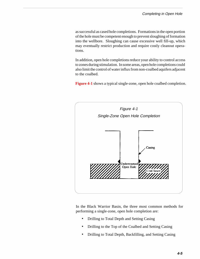
tiononha-
ssuldt
Completing in Open Hole
as successful as cased hole completions. Formations in the open porof the hole must be competent enough to prevent sloughing of formatiinto the wellbore. Sloughing can cause excessive well fill-up, whicmay eventually restrict production and require costly cleanout opertions.
In addition, open hole completions reduce your ability to control acceto zones during stimulation. In some areas, open hole completions coalso limit the control of water influx from non-coalbed aquifers adjacento the coalbed.
ion.
Figure 4-1 shows a typical single-zone, open hole coalbed completfor
Figure 4-1
Single-Zone Open Hole Completion
In the Black Warrior Basin, the three most common methodsperforming a single-zone, open hole completion are:
• Drilling to Total Depth and Setting Casing
• Drilling to the Top of the Coalbed and Setting Casing
• Drilling to Total Depth, Backfilling, and Setting Casing
4-5
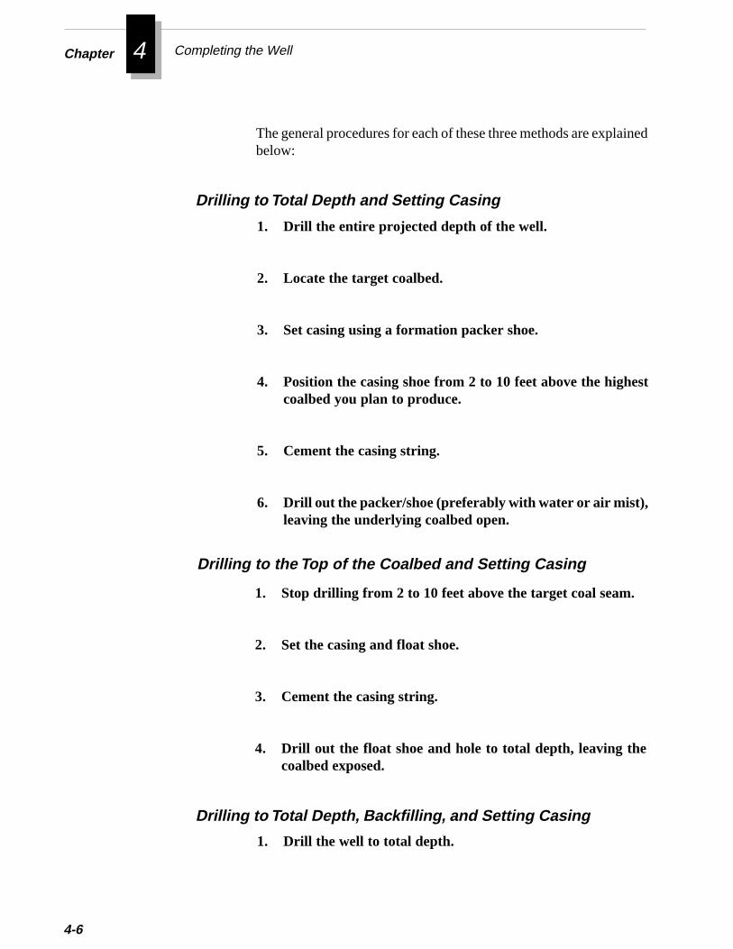
4Chapter Completing the Well
ed
4-6
The general procedures for each of these three methods are explainbelow:
1. Drill the entire projected depth of the well.
2. Locate the target coalbed.
3. Set casing using a formation packer shoe.
4. Position the casing shoe from 2 to 10 feet above the highestcoalbed you plan to produce.
5. Cement the casing string.
6. Drill out the packer/shoe (preferably with water or air mist),leaving the underlying coalbed open.
Drilling to Total Depth and Setting Casing
1. Drill the well to total depth.
Drilling to the Top of the Coalbed and Setting Casing
1. Stop drilling from 2 to 10 feet above the target coal seam.
2. Set the casing and float shoe.
3. Cement the casing string.
4. Drill out the float shoe and hole to total depth, leaving thecoalbed exposed.
Drilling to Total Depth, Backfilling, and Setting Casing
odtenes.
n holehelporef the
Completing in Open Hole
cksasen
n
s.
ss
2. Backfill the hole to the casing point (2 to 10 feet above thecoalbed) using sand or other such fill material.
Completing multiple coal seams in open hole is similar to the methfor completing a single zone in open hole. However, to complemultiple seams, you use open hole inflatable packers to separate zo
In each of these methods, you can also underream or enlarge the opeportion to remove near-wellbore damage. Underreaming may establish economical production from the reservoir if the wellbintersects the natural fractures in the coal and if the permeability ocoal is high enough to drain a large area of the reservoir.
5. Wash the fill material from the well, leaving the coalbed open.
4. Cement the casing string.
3. Lower the casing to the top of the fill material.
Open hole completions were used with limited success in the DeerliCreek Field in the Black Warrior Basin. However, this method waabandoned because of operational problems and resulting low gproduction rates. In general, open hole completions have not proveffective for multiple-zone wells.The main disadvantages of the multiple-zone open-hole completio
method are:
❖ Separating zones is impractical if pay stringers are thin.
❖ Inflatable packers must be removed after each treatment.
❖ Packers may leak and cause communication between zone
❖ Fluids may leak past the packer because of hairline strefractures in the formation caused by the packer.
❖ Some open holes are too irregularly shaped for a packer toseal effectively.
Multiple Coal Seams in Open Hole
4-7
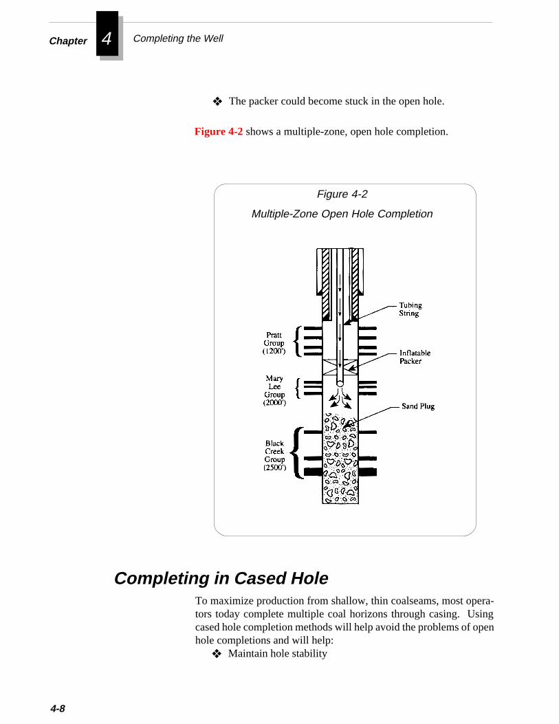
4Chapter Completing the Well
4-8
❖ The packer could become stuck in the open hole.
Figure 4-2 shows a multiple-zone, open hole completion.
Figure 4-2
Multiple-Zone Open Hole Completion
Completing in Cased HoleTo maximize production from shallow, thin coalseams, most opera-tors today complete multiple coal horizons through casing. Usingcased hole completion methods will help avoid the problems of openhole completions and will help:
❖ Maintain hole stability
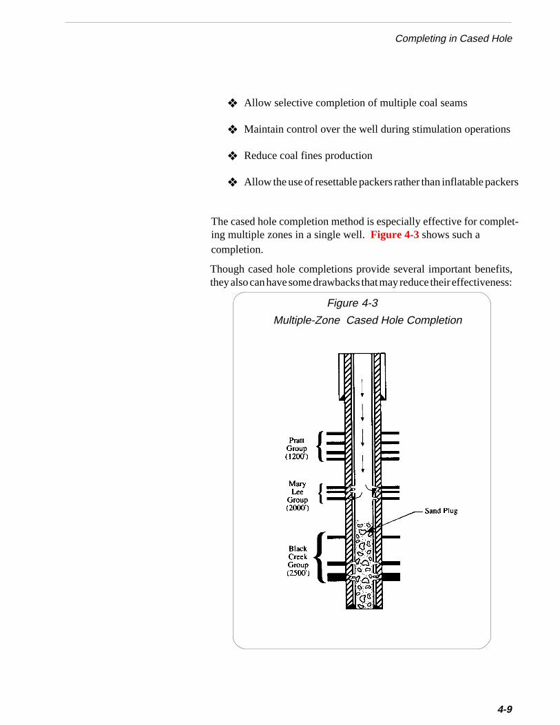
ers
Completing in Cased Hole
❖ Allow selective completion of multiple coal seams
❖ Maintain control over the well during stimulation operations
❖ Reduce coal fines production
❖ Allow the use of resettable packers rather than inflatable pack
plet-
fits,ness:
The cased hole completion method is especially effective for coming multiple zones in a single well. Figure 4-3 shows such acompletion.
Though cased hole completions provide several important benethey also can have some drawbacks that may reduce their effective
Figure 4-3
4-9
Multiple-Zone Cased Hole Completion
4Chapter Completing the Well
d
4-10
❖ Cement invasion caused by fracturing the coal during cement-ing operations can cause formation damage.
❖ Blockage of access points (perforations or slots) because of coalabrasion during stimulation or because of coal movementbehind the casing during production.
At the Rock Creek project, a stage cementing technique was once usesuccessfully to prevent cement invasion into coal seams. For moreinformation on this technique, refer to Cementing the Casing String inChapter 2.
The Rock Creek project also tested a fracturing technique used by someoperators in the Black Warrior Basin that can reduce blockage of accesspoints during fracture stimulation. In this technique, called interseamcompletion, coal seams are fractured by initiating the fracture in non-coal formations adjacent to the coal layers. For more information oninterseam completions, refer to Special Formation Access Techniques,later in this chapter.
Accessing the formation means providing a physical pathway ofcommunication between the wellbore and the target formation. Ac-cess controls the effectiveness of well testing, stimulation treatments,and production operations. Without effective communication to theformation, it is not possible to accurately measure formation proper-ties such as permeability. During stimulation, the type of accessaffects the amount and type of coal abrasion. Conversely, duringproduction the access points control the quantity of fluid that can movefrom the formation into the wellbore.
This section first explains the formation access methods that operatorsin the Black Warrior Basin use most often and then it explains criteriafor selecting an access method.
Operators in the Black Warrior Basin have used a variety of methods
successful than others. Each of these methods is explained below:to access coal seams. Some of the methods have proven more
Accessing the Formation
Methods of Formation Access
Accessing the Formation
s.
ety
y
rento
ingeenn
ion
tt
nt,-
r
• Perforating Through Casing
• Jetting Slots Through Casing
• Special Formation Access Techniques
accessing coalbeds, especially when you are targeting multiple zoneUsing conventional wireline-conveyed perforating guns, you canaccess the formation rapidly and with pinpoint accuracy.
You can perforate the casing using either bullets or jet charges. Jcharges have largely replaced bullets in the oil industry because thepenetrate deeper in hard rock formations. However, bullets maprovide better penetration and hole uniformity in low density coalformations.
Perforations are available in a variety of sizes. A perforation diameteof 0.41 inches can provide sufficient formation access to reducpressure losses during fracturing and decrease pressure drawdown ithe wellbore during production. Smaller diameter shots providegreater penetration for channels through cement-invaded zones.
Operators in the Black Warrior Basin use a variety of perforatingcharges. Some operators prefer to perforate shallow coal seams uscharges that create a large hole size to maximize gas flow into thwellbore. However, for deeper coal zones, operators often sacrifichole size in favor of charges that penetrate deeper into the formatioand through any cement invasion. Most operators use a perforatiocharge that provides a hole size of 0.37 to 0.41 inches and a penetratof 8 to 13 inches.
Typically, you can effectively access a coalbed interval with shodensities of 4-12 shots per foot, depending on fracture treatmendesign and expected production rates. For more information ospecifications and operating procedures for perforating equipmenconsult with wireline service companies that have experience perforating coalbed wells in your area.
Perforations provide the most efficient and cost-effective method fo
Perforating Through Casing
4-11
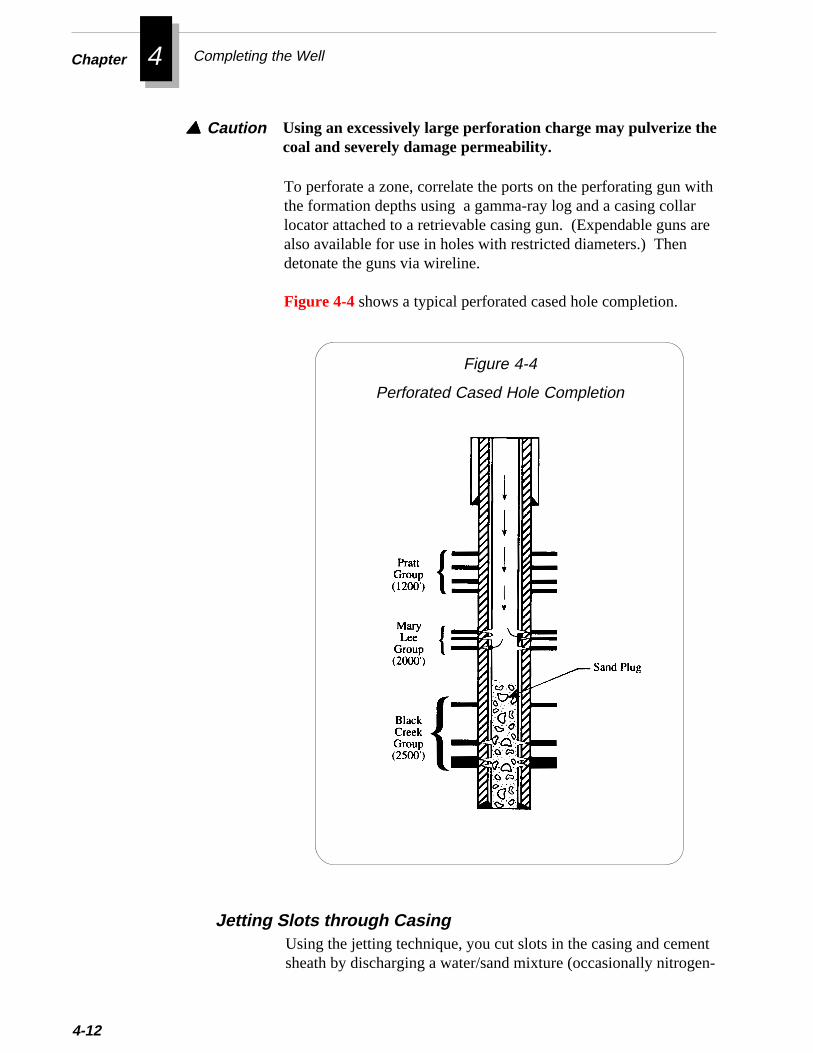
4Chapter Completing the Well
ithrare
4-12
Using an excessively large perforation charge may pulverize thecoal and severely damage permeability.
▲▲▲▲▲ Caution
To perforate a zone, correlate the ports on the perforating gun wthe formation depths using a gamma-ray log and a casing collalocator attached to a retrievable casing gun. (Expendable guns also available for use in holes with restricted diameters.) Thendetonate the guns via wireline.
Figure 4-4 shows a typical perforated cased hole completion.
ntn-
Figure 4-4
Perforated Cased Hole Completion
Using the jetting technique, you cut slots in the casing and cemesheath by discharging a water/sand mixture (occasionally nitroge
Jetting Slots through Casing
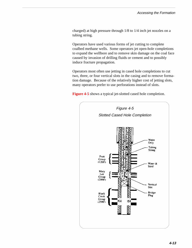
a
nsace
ta-s,
Accessing the Formation
charged) at high pressure through 1/8 to 1/4 inch jet nozzles on tubing string.
Operators have used various forms of jet cutting to completecoalbed methane wells. Some operators jet open-hole completioto expand the wellbore and to remove skin damage on the coal fcaused by invasion of drilling fluids or cement and to possiblyinduce fracture propagation.
Operators most often use jetting in cased hole completions to cutwo, three, or four vertical slots in the casing and to remove formtion damage. Because of the relatively higher cost of jetting slotmany operators prefer to use perforations instead of slots.
.
Figure 4-5 shows a typical jet-slotted cased hole completion4-13
Figure 4-5
Slotted Cased Hole Completion
4Chapter Completing the Well
4-14
To cut slots, coalbed methane operators normally use one of thesejet slotting procedures:
• The “Position-Move-Position” Procedure
• The “Reciprocating” Procedure
This method provides a series of individual holes in the casing. Touse this method, follow the steps below:
1. Rig up the workover rig and wireline truck.
2 . Install a jetting nozzle on the end of thet u b i n g .The jetting tool has a seat on which a ball can beused to plug the end of the tubing.
3 . Trip the tubing into the well to a depthwhere the end of the tubing is below thetarget zone.
4 . Run a gamma ray log down through the tub-ing and locate the target coal seam(s) bycorrelating this through-tubing gamma raylog with the openhole gamma ray log.
5 . Lower the gamma ray tool to the jettingnozzle and record the depth. Then raise thegamma ray tool up to the target zone andrecord this depth. Calculate the distancebetween these two depths and use thisvalue in step 7.
6 . Pull the gamma ray tool out of the tubing.
Using the “Position-Move-Position” Procedure
Accessing the Formation
7. Place a mark on the outside of the tubing at the top of theslips or at the top of the wellhead. Raise the tubing stringthe distance calculated in step 5 and place another mark onthe tubing above the slips or wellhead. This mark indicatesthe position that the tubing must be in to begin jetting.
8. Connect the injection lines from the pump truck to thetubing.
9 . Circulate water down the tubing, out thebottom opening of the jetting nozzle, andup the annulus to remove any debris thatmay plug the nozzles.
10. Drop a ball to shut off the bottom opening of the tool.Before running the jetting tool, make sure the ball is theproper size for the seat in the tool. On some tools, the tung-sten carbide nozzles may protrude into the throat of the tool,which reduces the I.D. above the ball seat.
1 1 . Circulate with water after the ball isdropped to make sure the ball has seated.When the ball is seated properly, you will notice apressure increase in the tubing.
1 2 . Begin jetting with water* containing a sandconcentration from 1 to 1-1/2 lb/gal. Jetin one place until you observe coal cuttingsat the surface.To better monitor returns, set up a screen whichwill trap the cuttings.
You should first observe metal cuttings from thecasing at the surface. These cuttings may be sosmall that you have to use a magnet in the returnstream to identify them.
When you have cut through the casing, you should
4-15
4Chapter Completing the Well
of
4-16
observe return water that is black or dark. This color is fromthe coal fines.
After the color of the water changes, you should begin seeingcoal cuttings at the surface.
13. After you see coal cuttings at the surface, move the tubingone or two inches to reposition the nozzle.
14. Begin jetting again, and monitor returns for metal cut-tings and coal cuttings.After the first slot is cut, the water may remain dark for therest of the slotting operation.
15. Repeat steps 14 through 16 until you have slotted theentire target interval.
16. After the interval has been slotted, stop pumping sandand circulate clean water until the returns are free of coalcuttings.The water may remain dark if you are cycling the water, butthe coal cuttings should stop when the well is cleaned up.
17. When the returns are clean, shut down the pump andreverse the circulation by pumping down the annulus andup the tubing string to remove the ball in the nozzle.
18. After the ball is at the surface, lower the tubing stringslowly while reverse circulating to clean out the casing tobottom.Monitor pump pressure closely. Large pieces of coal canplug the small opening at the bottom of the tool and cause arapid increase in pump pressure.
* You may circulate nitrogen instead of water for slotting. Nitro-gen can enhance cutting because it removes cuttings morequicklythan water. It also ensures returns to the surface.
Though most coal seams can support the hydrostatic pressurea column of water, some seams may not. If a seam cannotsupport a water column, you would not be able to observe the
rns
by
of
g
Accessing the Formation
returns at the surface. In such cases, using nitrogen will lowerthe hydrostatic pressure on the seam and allow you to get retuto the surface. Though nitrogen is more expensive than water,the additional cost may be offset by reduced slotting time.
▲▲▲▲▲ Caution This method may partially fill the coalbed near the
wellbore with sand and coal fines, which can make later frac-turing and production operations difficult. This problemoccurs because the slots created directly above or below the jetprevent the jet stream from circulating properly back into thewellbore.
Using the “Reciprocating” ProcedureA more effective jetting method is called “reciprocating.” Thismethod involves moving the jet up and down continuously untilyou observe coal returns at the surface of the well.
This procedure cuts a continuous vertical slot through the casing a sand-fluid mixture discharged at high pressure through jetnozzles. Constant washing of the slotted area minimizes buildupdebris. Continuous slots are more likely to be clear and open forlater fracturing and production operations.
To use this method, follow the steps below:
1. Rig up the workover rig and wireline truck.
2. Install a jetting nozzle on the end of the tubing.The jetting tool has a seat on which a ball can be used to pluthe end of the tubing.
3. Trip the tubing into the well so the end of the tubing isbelow the target zone.
4. Run a gamma ray log down through the tubing and locatethe target coal seam(s) by correlating this through-tubinggamma ray log with the openhole gamma ray log.
4-17
4Chapter Completing the Well
4-18
5. Lower the gamma ray tool in the tubing to the jetting nozzleand record the depth. Then raise the gamma ray tool up to thetarget zone and record this depth. Calculate the distancebetween these two depths and use this value in step 7.
6. Pull the gamma ray tool out of the tubing.
7. Place a mark on the outside of the tubing at the top of the slipsor the top of the wellhead. Raise the tubing string the distancecalculated in step 5 and place another mark on the tubing at thetop of the slips or wellhead. This mark indicates the positionthat the tubing must be in to begin jetting.
8. Draw a vertical line on the tubing in a place that can bereferenced to a stationary point on the rig floor or the wellhead.This line will be observed when reciprocating the pipe to make surethe pipe does not rotate. Preventing the pipe from rotating willensure the jetting nozzle is properly oriented inside the casing.
9. Connect the injection lines from the pump truck to the tubing.
10. Circulate water down the tubing, out the bottom opening ofthe jetting nozzle, and up the annulus to remove any debristhat may plug the nozzles.
11. Drop a ball to shut off the bottom opening of the tool.Before running the jetting tool, make sure the ball is the propersize for the seat in the tool. On some tools, the tungsten carbidenozzles may protrude into the throat of the tool, which reduces theI.D. above the ball seat.
12. Circulate with water after the ball is dropped to make sure theball has seated.When the ball is seated properly, you will notice a pressureincrease in the tubing.
13. Begin jetting with water* containing a sand concentration
e
ee a
rn
g
e
hese
Accessing the Formation
from 1 to 1-1/2 lb/gal while reciprocating the pipe up anddown across the interval to be slotted. Watch the vertical linemarked on the tubing to make sure the pipe does not rotate.Continue jetting and reciprocating until you observe a con-tinuous stream of coal cuttings at the surface.To better monitor returns, set up a screen which will trap thcuttings.
You should first observe metal cuttings from the casing at thsurface. These cuttings may be so small that you have to usmagnet in the return stream to identify them.
When you have cut through the casing, you should observe retuwater that is black or dark. This color is from the coal fines.
After the color of the water changes, you should begin seeincoal cuttings at the surface.
14. Repeat step 13 until you have slotted the entire targetinterval.
15. After the interval has been slotted, stop pumping sand andclean up the well by circulating clean water until the returnsare free of coal cuttings.The water may remain dark if you are cycling the water, but thcoal cuttings should stop when the well is cleaned up.
16. When the returns are clean, shut down the pump and reversethe circulation by pumping down the annulus and up thetubing string to remove the ball in the nozzle.
17. After the ball is at the surface, lower the tubing string slowlywhile reverse circulating to clean out the casing to bottom.Monitor pump pressure closely. Large pieces of coal can plug tsmall opening at the bottom of the tool and cause a rapid increain pump pressure.
* You may circulate nitrogen instead of water for slotting. Nitro-gen can enhance cutting because it removes cuttings morequickly than water. It also ensures returns to the surface.
4-19
4Chapter Completing the Well
4-20
Though most coal seams can support the hydrostatic pressure ofa column of water, some seams may not. If a seam cannotsupport a water column, you would not be able to observe thereturns at the surface. In such cases, using nitrogen will lowerthe hydrostatic pressure on the seam and allow you to get returnsto the surface. Though nitrogen is more expensive than water,the additional cost may be offset by reduced slotting time.
• Interseam Completion
Restricted Access CompletionA special formation access technique called “restricted accesscompletion” was developed at the Rock Creek project to propagatemore effective fractures. Restricted access refers to the techniqueof perforating only one seam in a group of thin, closely-spacedseams. The primary objective of restricting access to a single seamis to stimulate multiple seams (via the single seam) without theexpenseof perforating and treating each thin seam individually. The tech-nique also offers the following potential benefits:
❖ Helps prevent high pressures during stimulation
❖ Helps prevent propagation of multiple parallel fractures
❖ Reduces excessive fracture height growth
❖ Reduces migration of sand and coal fines
Special Formation Access TechniquesIn the Black Warrior Basin, three specialized formation accesstechniques have been used to complete multiseam wells. Thesetechniques are: • Restricted Access Completion
• Limited Entry Completion
Tests conducted at the Rock Creek project demonstrated the effective-ness of the restricted access technique. Monitor well data, interferencetesting, dye tracing, and reservoir modelling all confirmed that frac-ture treatments initiated at the bottom of the multi-layer Black Creekinterval are at least as effective as fracturing stimulations conductedeach individual layer of the interval. Figure 4-6 illustrates the fracturecommunication created in the Black Creek Coal Group by the re-stricted access completion technique.
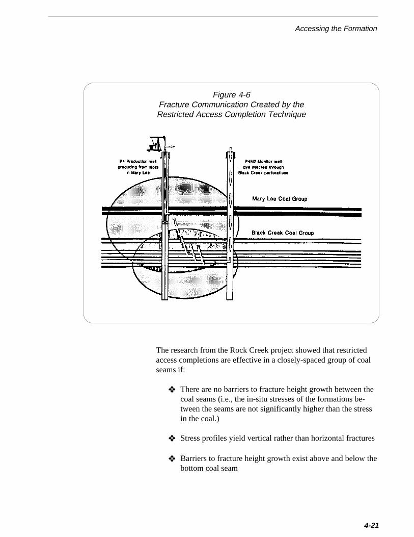
Accessing the Formation
Figure 4-6Fracture Communication Created by theRestricted Access Completion Technique
The research from the Rock Creek project showed that restrictedaccess completions are effective in a closely-spaced group of coalseams if:
❖ There are no barriers to fracture height growth between thecoal seams (i.e., the in-situ stresses of the formations be-tween the seams are not significantly higher than the stressin the coal.)
❖ Stress profiles yield vertical rather than horizontal fractures
❖ Barriers to fracture height growth exist above and below thebottom coal seam
4-21
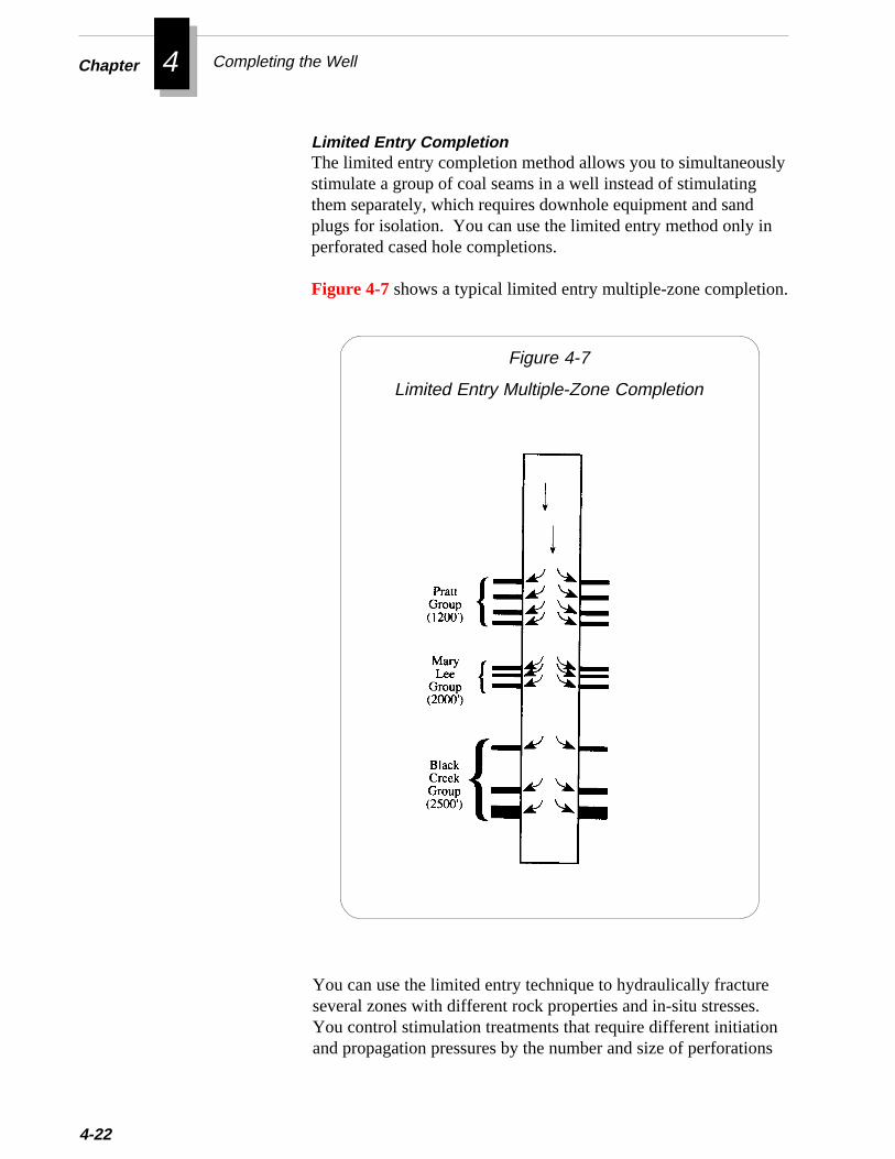
4Chapter Completing the Well
sly
n
n.
4-22
Limited Entry CompletionThe limited entry completion method allows you to simultaneoustimulate a group of coal seams in a well instead of stimulatingthem separately, which requires downhole equipment and sandplugs for isolation. You can use the limited entry method only iperforated cased hole completions.
Figure 4-7 shows a typical limited entry multiple-zone completio
.
ns
Figure 4-7
Limited Entry Multiple-Zone Completion
You can use the limited entry technique to hydraulically fractureseveral zones with different rock properties and in-situ stressesYou control stimulation treatments that require different initiationand propagation pressures by the number and size of perforatio
Accessing the Formation
you place across each zone. Adjusting the number and size ofperforations at each zone controls the friction pressure through theperforations, which gives you some control over the treating pres-sure at each zone.
The main benefit of a properly designed limited entry completion isthe ability to fracture multiple seams with one treatment. To besuccessful, a limited entry completion must be designed to providesufficient rate into each seam to adequately widen and extend thefracture.
The ability to widen and extend the fracture is a function of themechanical properties (Young’s Modulus and Poisson’s Ratio) ofthe formations. To properly design a limited entry completion, youmust analyze the mechanical properties of each coal seam and itsadjacent formations and account for the differing properties of eachzone in the design. A design with perforations based solely on thethickness of the coal seam will likely not be an optimum design.
An improperly designed limited entry completion couldcause the problems listed below:
❖ Propagation of a fracture at each set of perfora-tions may result in a shorter fracture length and agreater fracture height than desired
❖ Inadequate injection rates into each set of perfo-rations which could cause poor proppant trans-port, excessive fluid leakoff, and potential bridg-ing in the fracture because of insufficient fracturewidth
The limited entry completion will likely be most successful whenused to fracture multiple coal seams in the same coal group wherethere are confining barriers between the seams to be fractured. (Aconfining barrier is a zone that has a higher stress than the zone tobe fractured and is thick enough to restrict the height growth of theinduced fracture.) If the seams do not have confining barriersbetween them, a restricted access completion may work moreeffectively than a limited access completion. The restricted accesscompletion is discussed in the next section.
The limited entry completion has not been as successful for fracturingmultiple coal groups as it has for fracturing multiple seams within one
4-23
4Chapter Completing the Well
ens
octly
ioru-ingoal
it fortion
rengeamcoalst
e-s.-bem
4-24
coal group. This variation in performance might be due in part to thdegree of difference in the mechanical properties of the formatiobetween the coal groups.
Interseam CompletionsThis completion technique involves perforating through casing introck partings above, below, or between coal seams rather than direinto the seams.
Interseam completions have been attempted in the Black WarrBasin to complete coal zones for which conventional fracture stimlation pressures were excessive. In the basin, unusually high treatpressures are sometimes encountered while attempting to fracture cseams. In some cases, treating pressures may reach the safe limthe casing before the operator has established any substantial injecrate.
At the Rock Creek project, two separate coal groups in Well P5 wecompleted using the interseam technique. Though high treatipressures have not presented problems at Rock Creek, the interstechnique was used to assess its effectiveness. Despite having no directly connected to the wellbore, Well P5 became one of the highesustained gas producers in the field following its interseam compltion. In addition, Well P5 required no pump repairs for 2 1/2 year(On average, wells in the Black Warrior Basin require pump work 24 times a year). The results of this one test certainly cannot considered conclusive; however, they do indicate that interseacompletion may be effective for some wells.
beoal
resed
ent
Figure 4-8 shows the lithology and location of perforations for theWell P5 interseam completion.
The decision to complete wells with the interseam technique shouldbased on a thorough understanding of the in-situ stresses of the cseams and surrounding strata.
Though the usefulness of the interseam completion technique requifurther investigation, the technique may offer the advantages listbelow:
❖ High treatment pressures may be avoided
❖ Several target seams may be connected with a single treatm

itc-
Accessing the Formation
❖ A propped fracture initiated in interseam strata may inhibplugging by migrating coal fines and proppant during prodution
Figure 4-8
Lithology of the Well P5 Interseam Completion
4-25
4Chapter Completing the Well
,
e
ed
-
e
4-26
Selecting a Formation Access MethodTo determine the most effective formation access technique to useyou must consider how the technique will affect your efforts tocharacterize the reservoir, fracture the coal seams, and produce thwell. This section explains these considerations.
In wells where it is important to determine permeability, reservoirpressure, or stimulation pressure, you should use the slottingtechnique. Because slotting yields a larger access area, it canprovide more accurate reservoir pressure measurements. Toprovide for accurate measurement of reservoir pressures, it isrecommended to perform slotting in all pilot wells and in 10-20%of all development wells.
In the Black Warrior Basin, permeabilities derived from pressuretransient tests have been very erratic and often cannot be correlatwith production rates. The inconsistency of the permeabilityvalues could have been caused by insufficient access to the formation during these tests.
Access for Reservoir Characterization
During fracturing stimulation, you must try to minimize theamount of destruction to the coalbed. Because of the friable naturof coal, the fracture slurry can severely abrade the coal. Thisabrasion may cause the fracture fluid to prematurely load withsolids, which can lead to “tip plugging” or premature “bank fill-ing.” (For more information on these problems, refer to Chapter5.) By selecting the correct type of access and location of access,you can reduce coal destruction and its associated problems.
In the Black Warrior Basin, experience has shown that the mosteffective access for fracturing is obtained by perforating the casingwith a casing gun having a charge size between 16 and 23 grams.This charge will create a hole size of approximately 0.37 to 0.41inch and a depth of penetration from 11 to 20 inches.
During production of a well, formation access must provide a mini-mal pressure drop between the wellbore and the target formation.
Access for Production of the Well
Access for Hydraulic Fracturing
n-
f
e ft
Selecting Production Tubing
The access also must be able to maintain this low pressure differetial for the life of the well (often 10 to 20 years.)
You should not perforate or slot the casing until just before youfracture the well or place it on production. In some areas, leav-ing a coal seam exposed for an extended time without producingit may result in higher than expected treating pressures.
Selecting Production TubingSelecting the proper tubing string helps ensure the well is capableof producing the water rates necessary to effectively de-water thereservoir and maximize gas production. When selecting a tubingstring, consider the guidelines below:
■■■■■ Select tubing size based on the estimated maximum waterrate to be produced, the type and size of pump you will use,and the formation pressures expected.Most operators in the Black Warrior Basin use 2-3/8 inchtubing for shallow wells (2000 ft or less) and 2-7/8 inch tubingfor deeper wells and/or wells expected to produce high rates owater.
■■■■■ When ordering the tubing string, order enough tubing soyou can set the pump below the lowermost coal seam.Consider also having tubing on location to wash out the wellto bottom if necessary.Pup joints usually are not necessary unless you need to set thpump at a precise depth. For example, if there is less than 30between the lowermost coal seam and the bottom of the hole,you may use pup joints to place the pump below the perfora-tions without setting the tubing on bottom.
Working Over WellsAny work on a well (after drilling) that requires a rig can be gener-ally classified as one of the three operations listed below:
Completion - the operations necessary to prepare a well forproduction. Completions are usually performed after casing has
❈❈❈❈❈ Important
4-27
4Chapter Completing the Well
.
4-28
been set. Completion operations can include running cement bondevaluation tools, perforating or slotting, stimulating the reservoir,and installing artificial lift equipment.
Workover - remedial operations on a well which has producedpreviously. These operations may include repairing primarycement jobs, changing or adding perforated intervals, cleaning outthe wellbore, repairing casing failures, etc.
Pulling Job - the operations necessary to retrieve a downholepump and/or sucker rod string for replacement or repair. If atubing-retrievable pump is used, you must pull the tubing string.However, if an insert pump is used, you may retrieve the pump bypulling the rods. You can retrieve the rotor from a progressingcavity (PC) pump by pulling the rods, but to retrieve the statorfrom a PC pump, you must pull the tubing string.
Because of the marginal economics of most coalbedmethane wells, you must perform workovers prudently. Forexample, some operators work over a well only after its productionhas declined significantly. They find it more economical to deferworkovers as long as possible and to continue producing gas at alower rate. Of course, this practice will vary from well to welldepending on the difference between the cost of the workover andthe revenue from lost gas sales.
To minimize workover costs, you should plan the workover care-fully. The guidelines below will help ensure an economicalworkover:
■■■■■ Learn as much as you can about your well and offset wellsso you can determine the type of equipment needed to dothe job safely and effectively.
■■■■■ Make sure you perform only operations that are essential.
■■■■■ Evaluate several different options for performing a job.The most expensive option is not necessarily the most effective
a-
y
e
Working Over Wells
■■■■■ Bid out as much of the work as practical to get the bestprice.Investigate the reputation and quality of previous work per-formed by unknown contractors. The lowest price bid may notbe a bargain if the work is unsatisfactory.
■■■■■ Schedule all equipment to be on location when needed toavoid downtime waiting on equipment and to avoid standbycosts if equipment arrives too early.
Though economics requires prudent spending on workoveroperations, you should not jeopardize the safety of workers byeliminating or reducing necessary safety equipment.
The equipment most commonly used for coalbed methaneworkovers and completions is described below:
Operators normally use compression or tension packers for stimultion treatments, for testing zones and for squeeze cementing.Compression packers are used for deeper applications because therequire sufficient tubing weight above them to set. Usually, theminimum required setting weight is 4,000 - 5,000 lbs. When using2-3/8 inch, 4.7 lb/ft production tubing, the minimum depth forsetting a compression packer is approximately 850 feet. For shal-lower depths, you should use a tension packer.
Retrievable bridge plugs are normally used to isolate zones fortesting or for production. Retrievable bridge plugs can be tubingset/tubing retrievable or wireline set/tubing retrievable. The tubingset/tubing retrievable bridge plugs are set and retrieved in much thsame way as retrievable packers. If you use a retrievable bridgeplug in combination with a retrievable packer, make sure thedirection of rotation required to set the bridge plug and packer arenot the same. If the rotations are the same, the packer and bridgeplug will both set.
❈❈❈❈❈ Important
Equipment for Workovers and Completions
Retrievable Bridge Plugs
Packers
4-29
4Chapter Completing the Well
4-30
e
s
d
Perforating Guns
Zone Isolation Packer
Before perforating a zone, you must run a cased hole gamma raylog to correlate depths with the open hole gamma ray log. Becausperforation intervals are usually selected from the open holegamma ray, you should correlate the cased hole log as precisely apossible.
Conventional casing perforating guns are normally used to perfo-rate coalbed methane wells. Before running a perforating gun inthe wellbore, make sure the correct number of charges is loaded.Also, make sure length of the charges from one end to the other isequal the desired perforated interval. You should also note thedistance from the collar locator tool to the top shot so you positionthe gun at the correct depth before firing. Keep in mind that you(not the wireline operator) are responsible for ensuring that theperforations are shot in the right location. After firing the gun andpulling it out of the hole, check to see that all shots fired.
An underreamer is a tool which may be run through casing toenlarge an openhole section below the casing. The tool is equippewith cutter arms which are normally held within the tool body by acoil spring. When the tool is in the openhole below the casing, thecutter arms may be extended by applying pump pressure throughthe tubing string. In medium or soft formations, mostunderreamers can enlarge a hole up to twice the diameter of thetool. The typical tool size for 5-1/2 inch casing is 4-1/2 inches.This size tool can enlarge a hole up to 9 inches.
The zone isolation packer (ZIP) is a modified surface inflatablepacker developed by Gas Research Institute (GRI) at the RockCreek project. By installing the ZIP tool in the tubing stringbetween an upper and lower coal seam, the ZIP can be inflated toeffectively isolate the upper zone’s gas production from the lowerzone. Gas production from the upper seam can then be measureduntil the water level rises above the perforations. Because the ZIPtool has a full opening bore, it will not restrict flow rates.
Underreamer
Gamma Ray Log

l isn
ion
Working Over Wells
steel line strapped to the outside of the tubing string. A ZIP tooalso available with a “pass-through,” which enables you to run ainflation line through the tool to another ZIP installed below it.For more information on using the ZIP tool to measure productin multiple-seam wells, refer to Chapter 9.
❖ ❖ ❖
4-31
4Chapter Completing the Well
4-32
Additional Resources
Lambert, S.W.,“Comparison of Open Hole, Slotting, and Perfora-tion Completion Methods for Multiseam Coalbed Gas Wells,”Proceedings of the 1989 Coalbed Methane Symposium, The Uni-versity of Alabama, Tuscaloosa, Alabama (April 17-20).
Lambert, S.W. et al, “Multiple Coal Seam Well CompletionExperience in the Deerlick Creek Field, Black Warrior Basin,Alabama,” Proceedings of the 1987 Coalbed Methane Sympo-sium, The University of Alabama, Tuscaloosa, Alabama(November 16-19).
Lambert, S.W., M.A. Trevits, and P.F. Steidl, “Vertical BoreholeDesign and Completion Practices to Remove Methane Gas fromMineable Coalbeds,” U.S. Department of Energy, CarbondaleMining Technology Center, Carbondale, Illinois (1980).
Schraufnagel, R.A., J.L. Saulsberry, and S.W. Lambert, “GasProduction from Multiple Completion Wells at Rock Creek,”Proceedings of the 1989 Coalbed Methane Symposium, The Uni-versity of Alabama, Tuscaloosa, Alabama (April 17-20).
Schraufnagel, R.A., S.D. Spafford, and J.L. Saulsberry, “MultipleSeam Completion and Production Experience at Rock Creek,”Proceedings of the 1991 Coalbed Methane Symposium, The Uni-versity of Alabama, Tuscaloosa, Alabama (May 13-17).
Spafford, S. D., “Stimulating Multiple Coal Seams at Rock CreekWith Access Restricted to a Single Seam,” Proceedings of the1991 Coalbed Methane Symposium, The University of Alabama,Tuscaloosa, Alabama (May 13-17).

5 Fracturing Coal Seams
tes.
coal. coal,thetab- Thelly
igh afternnel
ntoring
tocallyues
T hough most coals are naturally fractured, you normally need to
• Performing a Minifracture Test
• Planning a Fracture Treatment Design
• Preparing for a Fracture Treatment
• Performing a Fracture Treatment
• Evaluating a Fracture Treatment
hydraulically fracture coal seams to produce economic gas flow ra
In the reservoir, methane gas is adsorbed onto the surface of theAfter the reservoir pressure is lowered and the gas desorbs from theit flows through the natural fractures in the coal. For gas to flow to wellbore at economical rates, effective communication must be eslished between the natural coal fractures or cleats and the wellbore.most effective way to create this communication is by hydraulicafracturing the coal seam.
In fracturing, large volumes of fluid and sand are pumped at hpressure down the wellbore. The fluid opens a crack in the coal, andthe fluid is removed, the sand remains in place to keep the new chaopen. The resulting proppant-filled fracture provides a flow path ithe wellbore for water and gas. When successful, hydraulic fractucan greatly increase methane production from coal seams.
Though much conventional fracturing technology can be appliedcoalbed fracturing, many techniques have been developed specififor coalbed methane wells. This chapter will explain these techniqand help you in:
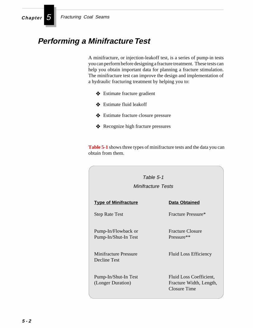
Fracturing Coal SeamsChapter 5
5 - 2
Performing a Minifracture Test
A minifracture, or injection-leakoff test, is a series of pump-in testsyou can perform before designing a fracture treatment. These tests canhelp you obtain important data for planning a fracture stimulation.The minifracture test can improve the design and implementation ofa hydraulic fracturing treatment by helping you to:
❖ Estimate fracture gradient
❖ Estimate fluid leakoff
❖ Estimate fracture closure pressure
❖ Recognize high fracture pressures
Table 5-1 shows three types of minifracture tests and the data you canobtain from them.
Table 5-1
Minifracture Tests
Type of Minifracture Data Obtained
Step Rate Test Fracture Pressure*
Pump-In/Flowback or Fracture ClosurePump-In/Shut-In Test Pressure**
Minifracture Pressure Fluid Loss EfficiencyDecline Test
Pump-In/Shut-In Test Fluid Loss Coefficient,(Longer Duration) Fracture Width, Length,
Closure Time

the
ts;
e-
toryeighta,rs
st
hessif.y-
Performing a Minifracture Test
* The fracture pressure for a coal is the pressure required tocreate a fracture. It equals the fracture gradient multiplied bythe depth of the coal.
** The fracture closure pressure is the pressure at which thestresses in the coal cause the induced fracture to close onto proppant. The fracture closure pressure is less than the frac-ture pressure.
Guidelines for Performing a Minifracture TestThis guide does not cover design or analysis of minifracture teshowever, you can find information on these topics in AdditionalResources at the end of this chapter.
Based on experience in the Black Warrior Basin, the general guidlines below will help you in performing a minifracture test:
■■■■■ Use pump-in/shut-in tests instead of pump-in/flowback tests.Traditionally, operators have used pump-in/flowback tests determine the fracture closure pressure in low-permeability (velow fluid loss) reservoirs. However, pump-in/shut-in tests armore effective for coalbed reservoirs, because they have a hfluid loss. Pump-in/shut-in tests provide useful pressure dacalled the “estimated closure pressure” (ECP). This data occuvery early in the pressure decline following a pump-in/shut-in teand, therefore, would be lost in a pump-in/flowback test.
■ Instruct the service company pumping the minifracture to usedigital pressure recording equipment to record pressure val-ues every few seconds.This step is necessary to obtain sufficient data for estimating t“effective closure pressure” (ECP) that best relates to the fluid lorate which occurred during the injection period. The ECP, applicable, will likely occur within the first few minutes of the testTherefore, you will need sufficient data points for accurate analsis.
5 - 3
Fracturing Coal SeamsChapter 5
5 - 4
■ Use the same fracture fluid and injection rate that you plan touse for the stimulation treatment.Because fluid loss in coal seams is essentially limited to the cleatand fracture system, the fluid loss rate is not controlled by a filtercake on the fracture face. Fluid viscosity plays an important role influid loss: higher viscosity fluids tend to exhibit lower fluid loss.
In conventional (porous rock) reservoirs, small changes inbottomhole treating pressure (BHTP) do not significantly alterfluid loss rate. However, the cleat system in coals may tend to“open” more and allow higher fluid loss when the BHTP increasesby even a small percentage.
Planning a Fracture Treatment Design
Designing an effective fracture treatment is a complex process thatrequires thoughtful consideration of formation properties, wellboredesign, and fracturing methods and materials. Because the require-ments of each fracture job are different, the combination of methodsand materials you select can determine the success of the job.
This guide does not provide specific procedures for designing afracture treatment. For assistance in designing a treatment, you mayconsult a variety of resources. You can contact a service company ora consulting firm with experience in fracturing coalbed methane wells.You might also talk with other operators in the area to learn what typesof fracture designs have proven successful for them.
In addition, you can utilize one of the many commercially availablefracture simulation models to test various treatment designs. Thoughyou can design a fracture treatment using hand calculations andgraphical methods, using fracture design software will enable you toquickly evaluate the effects of more design variables and conditions.
The primary information you will need to consider in designing afracture treatment are shown in Table 5-2 and are discussed below:
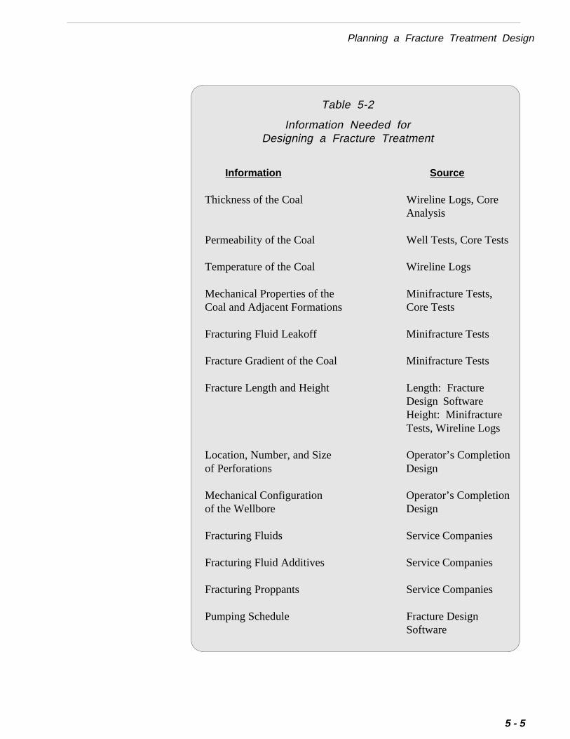
Planning a Fracture Treatment Design
Table 5-2
Information Needed forDesigning a Fracture Treatment
Information Source
Thickness of the Coal Wireline Logs, CoreAnalysis
Permeability of the Coal Well Tests, Core Tests
Temperature of the Coal Wireline Logs
Mechanical Properties of the Minifracture Tests,Coal and Adjacent Formations Core Tests
Fracturing Fluid Leakoff Minifracture Tests
Fracture Gradient of the Coal Minifracture Tests
Fracture Length and Height Length: FractureDesign SoftwareHeight: MinifractureTests, Wireline Logs
Location, Number, and Size Operator’s Completionof Perforations Design
Mechanical Configuration Operator’s Completionof the Wellbore Design
Fracturing Fluids Service Companies
Fracturing Fluid Additives Service Companies
Fracturing Proppants Service Companies
Pumping Schedule Fracture DesignSoftware
5 - 5

Fracturing Coal SeamsChapter 5
5 - 6
Thickness of the CoalCoal thickness will affect the number and type of perforations youuse across a coal group. For example, if a coal group is relativelythick and composed of many thin stringers, limited entry perforationmay be the most effective method for accessing the formation.However, if the interval is a thin coal group, then single zone entrymay be more successful. For information on various perforatingtechniques, refer to Accessing the Formation in Chapter 4.
The thickness of the coal also will affect the economics of thefracture design. Because coal thickness affects gas recovery, it is afactor in determining the fracture length needed to make make acoalbed methane well economical. In general, the greater the frac-ture length needed, the more costly will be the fracture treatment.To select a fracture length, you can run sensitivity evaluations tocompare the incremental cost of greater fracture length against thevalue of expected incremental gas recovery from the fracture.
For information on determining coal thickness from wireline logs,refer to Chapter 3.
Because most coal seams are relatively shallow, the formationtemperature does not cause premature degradation of the fracturingfluid. However, you must consider the relatively low temperaturewhen designing the schedule for gel breakers because the tempera-ture does not provide much help in breaking the gel. The circulat-ing bottomhole temperature is usually recorded on openhole logs.Make sure you adjust the recorded temperature to account for theshut-in time between circulating and conditioning the hole andlogging it. The bottomhole temperature from log correlations isoften underestimated.
For conventional wells, you can use the formation permeability toestimate increased production from a fracture treatment. However,for coalbed methane wells, permeability is only useful for estimat-ing the volume of fluid leakoff into the formation during thefracture treatment. For information on determining the permeabil-ity of coal, refer to Chapter 9.
Temperature of the Coal
Permeability of the Coal
Planning a Fracture Treatment Design
-
s
-
Mechanical Properties of the Coal and AdjacentFormations
The rock properties, Young’s Modulus and Poisson’s Ratio, areneeded for fracture propagation calculations in fracture simulators.The fracture gradient of the formation is a function of these twoproperties. For information on estimating mechanical rock proper-ties, refer to Chapter 3.
The vertical height of the fracture in a coalbed methane well oftenwill be much greater than the thickness of the coal. The height towhich a fracture will grow depends directly on the stresses in thezones above and below the coal seam. Thick, more highly stressedzones will tend to confine the fracture; thinner, less stressed zoneswill promote fracture growth.
When designing a fracture treatment, it is helpful to estimatefracture height. You can estimate fracture height by performing aminifracture test on zones adjacent to the coal seam. For an explanation of minifracture tests, refer to Performing a MinifractureTest at the beginning of this chapter.
Fracturing Fluid LeakoffIn many coalbed methane fracturing treatments, the fracturing fluidleaks off into the coal seam simply because the adjacent formationare too impermeable to accept fluid. The rate of fracturing fluidleakoff during a fracture treatment is a critical factor in fracturedesign. The rate of leakoff determines the fracturing fluid effi-ciency, which is the ratio of the volume of the induced fracture tothe volume treatment pumped. If the fluid efficiency of a fractur-ing treatment is underestimated, the treatment may screenoutprematurely. In addition, because fluid leakoff affects fractureclosure time, it may also affect distribution of proppant within thefracture.
The volume of fluid leakoff depends on the viscosity and wallbuilding ability of the fracturing fluid, the viscosity and compress-ibility of the formation fluid, and the relative permeability of thefluids. Though the properties of the fracturing fluids and formationfluids usually can be estimated fairly accurately, the relative permeability effects are more difficult to determine. Coal permeability isa function of the natural fractures in the coal, and estimating fluid
5 - 7

Fracturing Coal SeamsChapter 5
5 - 8
loss for a naturally fractured formation is more difficult than for anon-fractured reservoir.
To better define fluid loss characteristics for coals, Amoco con-ducted a field study in the Oak Grove Field (Black Warrior Basin).The study concluded that fluid efficiencies obtained fromminifracture tests are not always accurate. This inaccuracy stemsnot only from the natural fractures in coal, but also from the pres-sure dependent nature of coal permeability, and from the tendencyof proppants to bridge because of width constrictions in the frac-ture. For more information on the Amoco field study, see thepaper in Additional Resources at the end of this chapter.
r-
The fracture gradient of a coal seam or other formation can bedetermined from minifracture tests, discussed at the beginning ofthis chapter. You can estimate the fracture gradient by first measuing an instantaneous shut in pressure (ISIP). An ISIP is simply thepumping pressure required to fracture the formation minus thefriction pressure that must be overcome during pumping. Figure 5-1shows an ISIP.
Fracture Gradient of the Coal
Figure 5-1
Instantaneous Shut In Pressure (ISIP)
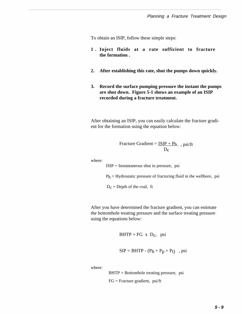
Planning a Fracture Treatment Design
To obtain an ISIP, follow these simple steps:
1 . Inject fluids at a rate sufficient to fracturethe formation .
2. After establishing this rate, shut the pumps down quickly.
3. Record the surface pumping pressure the instant the pumpsare shut down. Figure 5-1 shows an example of an ISIPrecorded during a fracture treatment.
After obtaining an ISIP, you can easily calculate the fracture gradi-ent for the formation using the equation below:
Fracture Gradient = ISIP + Ph , psi/ftDc
where:ISIP = Instantaneous shut in pressure, psi
Ph = Hydrostatic pressure of fracturing fluid in the wellbore, psi
Dc = Depth of the coal, ft
After you have determined the fracture gradient, you can estimatethe bottomhole treating pressure and the surface treating pressureusing the equations below:
BHTP = FG x Dc, psi
SIP = BHTP - (Ph + Pp + Pt) , psi
where:BHTP = Bottomhole treating pressure, psi
FG = Fracture gradient, psi/ft
5 - 9
Fracturing Coal SeamsChapter 5
5 - 1 0
Dc = Depth of the coal, ft
SIP = Surface injection pressure, psi
Ph = Hydrostatic pressure of fracturing fluid in the tubing, psi
Pp = Pressure drop across the perforations, psi
Pt = Pressure drop in the tubulars, psi
Fracture Length and HeightTwo of the most important factors in designing a fracture treatmentare the desired fracture length and the expected maximum fractureheight. The optimum fracture length depends on the permeabilityand gas content of the coal. To determine optimum fracture length,you can run a fracture model that simulates gas recovery over atime period for various fracture lengths at a given permeability andgas content. The optimum fracture length is the one that beyondwhich little incremental gas recovery is obtained.
The height to which a fracture will grow depends on the mechani-cal properties of the formations adjacent to the coal, as discussedabove in Mechanical Properties of the Coal and Adjacent Forma-tions. If fracture height is estimated incorrectly, then the fracturelength will be different than calculated in the design.
Because the mechanical properties of the coal and adjacent forma-tions are not always available or are not estimated accurately,fracture height is often estimated incorrectly. If the actual fractureheight is less than estimated in the design, the fracture may belonger than expected. However, if the actual fracture height isgreater than estimated in the design, the fracture will be shorterthan expected. Unfortunately, the latter case occurs much morefrequently than the former.
Location, Number, and Size of PerforationsIt is important to know the location of perforations so you canaccurately determine fluid displacement volumes and be able todivert fracture fluids if ball sealers are used in the treatment.
The number of perforations used will affect the injection rate. If youuse a very large number of perforations, the injection rate may be solow that a moderate to low viscosity fluid may be incapable of carryingproppant into the perforation tunnels. Conversely, using too few
of
t
l.
a
Planning a Fracture Treatment Design
If you are designing a limited entry fracture treatment, you should useenough perforations so that each perforation has a pressure drop only a few hundred psi. A common rule of thumb for a limited entrytreatment is to design for an injection rate of 1/4 to 1 BPM/perforation.For an explanation of the limited entry technique, refer to Accessingthe Formation in Chapter 4.
The size of the perforation could affect the selection of the proppansize. Each perforation must be large enough relative to the maximumproppant diameter to prevent bridging across the perforation tunneProppant bridging usually is not a problem in coalbed methane wellsbecause most wells are perforated with casing guns that provide perforation diameter of 0.37 - 0.41 inches. A perforation diameter of0.41 inch would not limit the concentration of 20/40 or 16/30 proppantto below the maximum concentrations (4-6 lb/gal) that are normallypumped in coalbed methane wells.
configuration of the casing and/or tubing strings in the wellbore. Yourselection of tubing and casing configuration will control the maximumpumping rate during the job as well as the flexibility to fracture singleor multiple coal zones.
Operators in the Black Warrior Basin use two general types ofwellbore configurations for fracturing: through-casing fracturing andthrough-tubing fracturing. In almost all cases, through-casing fractur-ing is the preferred method.
Mechanical Configuration of the Wellbore An important element in a fracture design is the
The discharge coefficient is a factor used to calculate frictionalpressure drop of fluid passing through the perforations. Perfora-tions have an initial discharge coefficient of about 0.6. After youbegin pumping proppant, the sand erodes the perforations andthe discharge coefficient usually increases to around 0.95. Thehigher the discharge coefficient, the lower the pressure differen-tial through the perforations. You should keep this guideline inmind both when designing the treatment and while pumping it.
❈❈❈❈❈ Important
5 - 1 1

Fracturing Coal SeamsChapter 5
gead
torere
alsTote
h-
is
ples
5 - 1 2
Through-Casing FracturingMost operators in the Black Warrior Basin fracture wells by pumpinthe treatment directly down the production casing string into thformation. To fracture through-casing, the low pressure casing heis removed and a high pressure frac valve is installed in its place.
If the wellbore contains open perforations shallower than the coalbe fractured, you should not fracture through-casing unless you acertain the shallower perforated intervals have a much higher fractupressure than will be used during the treatment. (Shallower intervnormally have a lower fracture pressure than deeper intervals.) help prevent fracturing shallow perforated intervals, you can isolathe perforations with a tubing and packer assembly.
Through-casing fracturing offers several advantages over the througtubing method:
❖ Allows pumping higher injection rates
❖ Provides flexibility for fracturing multiple coal seams in a well
❖ Requires less equipment downhole and at the wellhead andthus operationally simpler
The through-casing method can be used to fracture single or multicoal zones. Four different through-casing wellbore configurationhave been used in the Black Warrior Basin:
• Single Zone
• Multiple Zones Using Limited Entry Technique
• Multiple Zones Using Plugback Techniques
• Multiple Zones Using the Ball and Baffle Technique
Each of these applications are illustrated in Figure 5-2 and areexplained below.

-
Planning a Fracture Treatment Design
Figure 5-2
Wellbore Configurations for Fracturing
Single ZoneThe simplest through-casing method involves perforating or slotting a single coal seam and then pumping the fracturetreatment down the casing into the seam. The primary wellheadequipment needed for this method is a frac valve. No downholeequipment is required. Figure 5-2 (a) shows a single-zone,through-casing fracture treatment.
Multiple Zone Using Limited Entry TechniqueThe limited entry technique involves simultaneously fracturingseveral coal seams (with differing rock properties and in-situstresses) instead of fracturing individual seams (or groups of
5 - 1 3
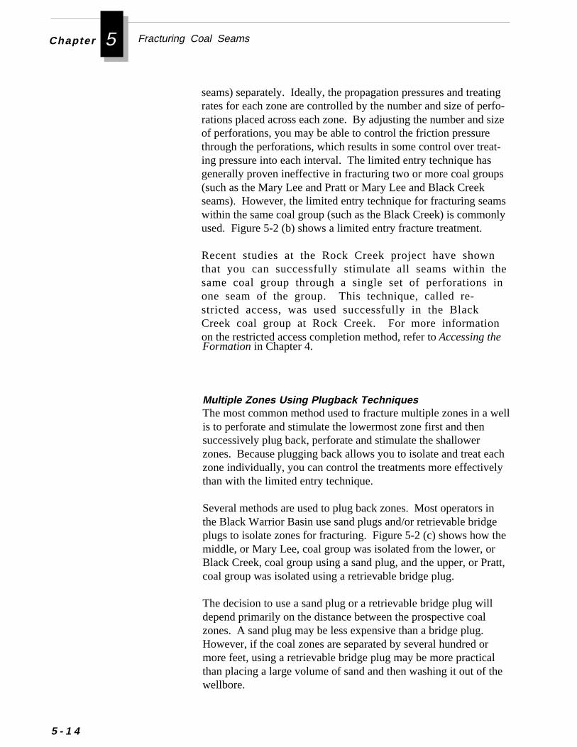
Fracturing Coal SeamsChapter 5
-e
ll
h
,
5 - 1 4
seams) separately. Ideally, the propagation pressures and treatingrates for each zone are controlled by the number and size of perforations placed across each zone. By adjusting the number and sizof perforations, you may be able to control the friction pressurethrough the perforations, which results in some control over treat-ing pressure into each interval. The limited entry technique hasgenerally proven ineffective in fracturing two or more coal groups(such as the Mary Lee and Pratt or Mary Lee and Black Creekseams). However, the limited entry technique for fracturing seamswithin the same coal group (such as the Black Creek) is commonlyused. Figure 5-2 (b) shows a limited entry fracture treatment.
Recent studies at the Rock Creek project have shownthat you can successfully stimulate all seams within thesame coal group through a single set of perforations inone seam of the group. This technique, called re-stricted access, was used successfully in the BlackCreek coal group at Rock Creek. For more informationon the restricted access completion method, refer to Accessing theFormation in Chapter 4.
Multiple Zones Using Plugback TechniquesThe most common method used to fracture multiple zones in a weis to perforate and stimulate the lowermost zone first and thensuccessively plug back, perforate and stimulate the shallowerzones. Because plugging back allows you to isolate and treat eaczone individually, you can control the treatments more effectivelythan with the limited entry technique.
Several methods are used to plug back zones. Most operators inthe Black Warrior Basin use sand plugs and/or retrievable bridgeplugs to isolate zones for fracturing. Figure 5-2 (c) shows how themiddle, or Mary Lee, coal group was isolated from the lower, orBlack Creek, coal group using a sand plug, and the upper, or Prattcoal group was isolated using a retrievable bridge plug.
The decision to use a sand plug or a retrievable bridge plug willdepend primarily on the distance between the prospective coalzones. A sand plug may be less expensive than a bridge plug.However, if the coal zones are separated by several hundred ormore feet, using a retrievable bridge plug may be more practicalthan placing a large volume of sand and then washing it out of thewellbore.
on
Planning a Fracture Treatment Design
b,eed
Multiple Zones Using the Ball and Baffle TechniqueThe ball and baffle technique is used to isolate coal seams byinstalling cast-aluminum baffle plates at pre-selected depths in thecasing string when the string is run in the hole. Figure 5-2 (d)shows a baffle frac job performed on Well P3 at the Rock Creekproject.
To isolate a perforated interval for fracturing, a rubber ball isdropped down the casing. The ball seats in the baffle and thusisolates the interval from treated deeper intervals. By installingbaffles with successively larger inside diameters (from the bottomupward), you can effectively isolate single seams or groups ofseams so they can be treated individually during the fracture job.
The ball and baffle technique offers two significant advantages.First, it saves time because you can fracture the zones in successiwithout having to trip tools in and out of the hole. Second, itallows you to flow back each fractured interval immediately afterthe fracture job. Though this technique was used successfully atthe Rock Creek project, it is not widely used for coalbed fracturingstimulations in the Black Warrior Basin.
Using a Tubing "Dead String" to Measure Bottomhole Pressure
To accurately determine bottomhole pressure during a fracture josome operators run a tubing “dead string” in the well. This techniqucan be used with any of the four through-casing techniques describabove. However, if you use bridge plugs or the ball and baffletechnique, you must pull the tubing between treatments.
e-
gatal to
Figure 5-3 illustrates a tubing dead string assembly run in a well at thRock Creek project to determine bottomhole pressure during fracturing of the Blue Creek seam.
Treatment fluids and proppant are pumped down the casing/tubinannulus. A pressure gauge or recorder installed on top of the tubing the surface provides accurate surface pressure data free from frictionpressure losses. You can then convert the surface pressure readingbottomhole treating pressure by using the equation below:
5 - 1 5
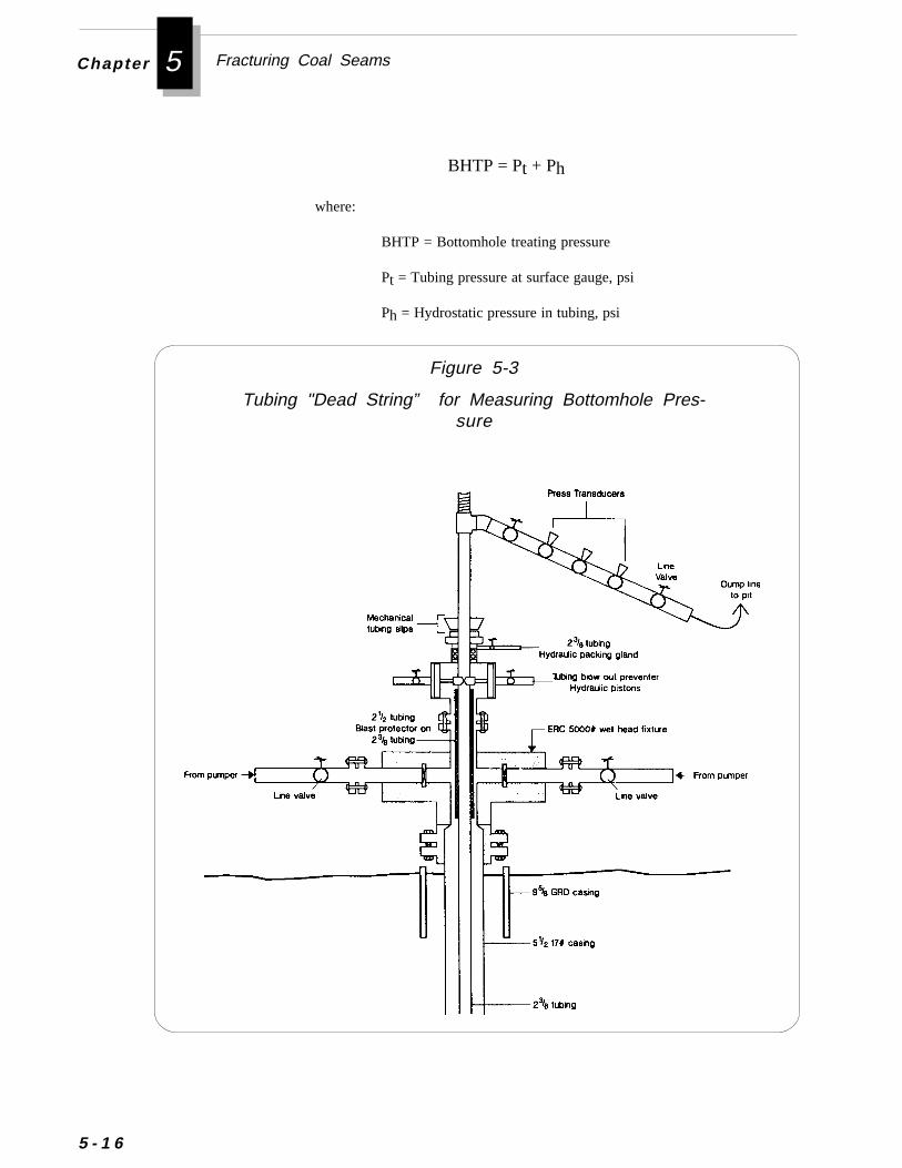
Fracturing Coal SeamsChapter 5
5 - 1 6
Tubin
BHTP = Pt + Ph
where:
BHTP = Bottomhole treating pressure
Pt = Tubing pressure at surface gauge, psi
Ph = Hydrostatic pressure in tubing, psi
Figure 5-3
g "Dead String” for Measuring Bottomhole Pres-sure
Planning a Fracture Treatment Design
When using a tubing dead string, you should place the tubing as closeto the coal interval as practical. You must also select a pressure gaugeor recorder that has a pressure rating greater than the maximumanticipated injection pressure.
To protect the tubing from the abrasion of the sand-laden fluid, a tubingdead string assembly requires several pieces of equipment. Thisequipment is described below:
Blast Joint A blast joint should be installed in the tubing string throughthe injection spool to prevent the abrasion of the proppant-laden fluidfrom cutting a hole in the tubing. At the Rock Creek project, a 2-3/8inch tubing string was used for the dead string. To eliminate the costfor a 2-3/8 inch blast joint, a 2-7/8 inch pup joint was placed over the2-3/8 inch non-upset tubing. The pup joint was supported on the bottomby a collar on the 2-3/8 inch string and on the top by the BOP rams, asshown in Figure 5-3.
Casing Spool A wellhead fixture similar to a casing spool with sideoutlets allows injection of fracture fluids into the tubing/casing annu-lus. The treatment is pumped through the side ports in the spool. Thespool is installed on the casing or casing head. (You may need athreaded companion flange if the casing is fitted with a threaded nippleand the spool is flanged.)
Blowout Preventer (BOP) A pipe ram BOP is installed on top of thecasing spool to contain the pressure in the tubing/casing annulus duringthe fracture job. To provide another pressure seal for additional safety,you may also install a stripper rubber head directly on top of the BOP.
Mechanical Tubing Slips Tubing slips are placed above the BOPto support the weight of the tubing.
Coal seams may be fractured with low injection rates. However, toadequately open and widen fractures, fracturing fluids must bepumped at relatively high rates to overcome high fluid leak-offrates. Therefore, fracturing coalbed methane wells through tubingis generally impractical because sufficient injection rates cannot beestablished.
Through-Tubing Fracturing
5 - 1 7
Fracturing Coal SeamsChapter 5
5 - 1 8
Many through-casing fracture jobs are performed at rates of 25-40BPM. The same fracturing treatment injected through-tubingwould have to be pumped at a lower rate. The actual maximuminjection rate will depend on the viscosity of the fluid used. Youmay be able to slightly increase through-tubing injection rates byadding friction reducers to the fluid.
You may justify a through-tubing stimulation in cases wherethrough casing treatments are not possible. For example, if thewellbore contains open perforations above the coal seam to befractured. Similarly, through-tubing fracturing may be used if pre-fracture testing indicates that fracturing pressure will exceed thedifferential burst pressure of the casing at shallow depths.
If you attempt to isolate perforations close to the seam youintend to fracture, you risk fracturing into the isolated perfora-tions. If the isolated perforations break down, proppant couldflow through these perforations into the wellbore and stick thepacker and pipe.
Selecting proper fracturing fluids is critical to a successful fracturingtreatment. These fluids help initiate the fracture in the formation,extend the fracture once it opens, and transport the proppant into thefracture.
To select the best fracturing fluid for a well, you should considerthese factors:
• Fluid Viscosity
• Formation Properties
• Frictional Pressure
• Fluid Loss Properties
• Economics
Fracturing Fluids
▲▲▲▲▲ Caution
Planning a Fracture Treatment Design
.
lde
e a
Fluid ViscosityViscosity may be the most critical factor in selecting a fluid. Aneffective fluid must not only initiate and extend a fracture, but alsocarry the proppant deep into the fracture. High viscosity fluids arenecessary to develop fracture width and to effectively transport theproppant. A fluid with insufficient viscosity will limit the fracturewidth and prevent the transport of proppants deep into the fracture
It is also important to select the appropriate breaker and breakerconcentration. No matter how good the proppant transport charac-teristics of the frac fluid, they can be completely negated by usingexcessive breaker concentrations.
When selecting fluids, make sure you obtain viscosity informationfrom the service company for the fluids you are considering using.You will need this information not only when designing the fracturejob, but also when monitoring the fluids during the fracture job.
To optimize the fracture treatment and prevent coal damage, thefracturing fluid must be compatible with the formation. In theBlack Warrior Basin, guar gum and hydroxypropyl guar (HPG) gelfluids have been used extensively for fracturing. However, recentGRI-sponsored research has indicated that HPG gels and guar couadversely affect the permeability to both water and gas. Experiencat Rock Creek has shown that guar and HPG gels can be usedsuccessfully, but they may also cause failure. For example, WellsP2 and P7 were both fractured in the Mary Lee formation with HPGgel, but Well P2’s post fracture production rate (190 MCFD) wassignificantly higher than that of Well P7 (40 MCFD). The poorperformance of the P7 treatment was attributed to the failure of thegel to break properly, which reduced permeability.
GRI research indicates that the ability of guar-based fluids to breakproperly is extremely important in determining the success or failurof stimulation treatments. Conversely, research also indicates thatbreak schedule that is too aggressive may result in a fluid that failsto form a filter cake. A high volume of fluid could then leakoff tothe cleat system and significantly impair production potential.
Field studies conducted by Amoco also indicate that HPG gel isdamaging to coal. Further, Amoco laboratory studies suggest thatall polymers (including HEC gels and other chemical additives) canirreversibly damage coals.
Formation Properties
5 - 1 9
Fracturing Coal SeamsChapter 5
itysf
k
tyet
h.
er-e
atee
-
5 - 2 0
The GRI and Amoco data suggest that you may reduce the possibilof damaging coal by using a fluid with low damage potential (such aKCl or a KCl substitute) or a fluid that contains a minimal amount ogel and that has a high fluid efficiency (such as foam).
Amoco has successfully fractured wells in the Oak Grove Field (BlacWarrior Basin) using water as the fracturing fluid. Similarly, GRI hassuccessfully fractured wells at the Rock Creek project using 75 qualifoam as the fracturing fluid. The greater fracture lengths that can bachieved with the foam fluid may offset any formation damage thamight be caused by the HEC gel used with the foam treatment.
Because nearly all coalbed methane wells are fractured througcasing, frictional pressure does not usually affect fluid selectionHowever, if you must fracture a well through tubing, the frictionalpressure may be the limiting factor in selecting a fluid.
Because of the natural cleat system in coals, fluidlosses during fracturing could be high. High fluid loss increasesthe probability of excessive deep damage to the cleat system.
When selecting a fracturing fluid, you must consider the cost of thtreatment relative to the results expected from it. For example, if youobjective is to create a short fracture that will simply ensure communication between the wellbore and the natural fracture system of thcoal, you may not need to use a high viscosity fluid. However, if youhave determined that a very long fracture length is needed to genereconomical production rates from the well, you should probably usa high viscosity fluid.
In the Black Warrior Basin, operators use only water-based fracturing fluids. There are four types of water-based fluids:
• Nongelled Water
• Linear Gel
• Crosslinked Gel
• Foam
Types of Fracturing Fluids
Economics
Fluid Loss Properties
Frictional Pressure
.
l
er,
Planning a Fracture Treatment Design
You can pump fresh water, or treated water at high rates to placelow concentrations of sand (e.g., less than 1 lb/gal) into fracturesHowever, if you use a water-based fluid, you will likely place theproppant a relatively short distance from the wellbore. Thepropped fractures from a water-based stimulation will be shortbecause of the poor transport capacity of water and because thecreated fractures are close to wellbore.
▲▲▲▲▲ CautionMake sure that any water used is compatible with the fractur-ing fluids you plan to pump. Do not use water flowed backfrom a previous fracture treatment unless it has been properly
treated.
Recent research sponsored by GRI has shown that using 2% KC(potassium chloride) water may help prevent formation damage.
You may also consider adding a natural or synthetic friction re-ducer to the water, allowing you to pump at a higher rate to carrythe proppant further out from the wellbore. Friction reducers mayalso allow you to use lower horsepower pumps. Before using afriction reducer, make sure it is compatible with the fracturingfluids you plan to use.
You can pump hydroxyethylcellulose (HEC) gel fluids to placesand concentrations of 1 to 3 lb/gal a moderate distance from thewellbore. Because these gelling agents gel quickly, you can usethem in continuous, semi-continuous, or batch processes.
Linear gels cannot hold proppants in perfect suspension. As theshear rate decreases in the fracture, the sand will settle. Howev
Sand-water fracture treatments are relatively inexpensive, butthey also require recovering large volumes of water after thetreatment.
❈❈❈❈❈ Important
Nongelled Water
Linear Gel Fluids
5 - 2 1
Fracturing Coal SeamsChapter 5
5 - 2 2
you can obtain greater propped fracture length with a linear gelfluid than with a water-based system. Linear gels also help reducefriction and control fluid loss.
To facilitate recovery of the gel fluid after the treatment, the gel isdesigned to revert or “break” to the viscosity of water. This break-down allows the stimulation fluid to drain from the fracture intothe wellbore.
Each service company uses different chemical systems to break gelfluids at various formation temperatures. Because the chemistry ofthese gel systems is complex, a carefully designed gel system iscritical to the success of the fracture job.
Linear gels clean up with breakers and produced load water andcan leave a highly conductive propped bed. The cost of a linear gelfracture is higher than for a water-based fracture treatment. How-ever, the longer propped length usually created by a linear gelshould provide greater production than a water fracture treatmentof the same size. Typically, the higher cost of a gel fracture isoffset by higher production rates.
For several years, operators in the Black Warrior Basin com-monly used hydroxypropyl guar (HPG) fluids for fracturing.However, recent research sponsored by GRI indicates thathydroxypropyl guar (HPG) fluids may adversely affect thepermeability to both gas and water.
Crosslinked gels were developed to provide a water-based fractur-ing fluid with a higher viscosity than linear gels. This higherviscosity can create wider, better propped, and more conductivefractures than linear gels. The viscosity of these fluids is increasedby adding special crosslinking systems and stabilizers.
Crosslinked gels can carry proppants in excess of 10 lbs/gal insuspension. As with linear gels, you can tailor crosslinked gels tobreak to a low viscosity fluid after fracture closure. However,crosslinked gels are more difficult to break than linear gels. Toensure recovery of the fracturing fluid and to reduce the potentialfor formation damage after the treatment, you should add sufficientbreaker to the gel.
❈❈❈❈❈ Important
Crosslinked Gel Fluids
Planning a Fracture Treatment Design
,
f
ity
n
ut
Foam Fluids
Foam fluids are created by dispersing gas, usually nitrogen, in aliquid. To initiate the dispersion, a surfactant is normally used as afoaming agent.
Because foams have high viscosity and low fluid leakoff propertiesthey can carry proppant further out into the formation than gelfracturing fluids.
Foam quality is the volumetric ratio of the gas to the total volume ofoam at downhole conditions. A 75 quality foam contains 75% gasby volume at downhole temperature and pressure.
Foams used for fracturing typically range from 65-85 quality. Foamfracturing treatments at the Rock Creek project have used 75 qualfoam. Higher quality foam provides greater viscosity, but also mayincrease pump pressure and limit maximum sand concentration.Foams with a quality less than 52 have a much lower viscosity thahigher quality foams and thus do not function as effectively as highviscosity fluids. Foams with a quality less than 52 are usuallyunstable.
Foams have several advantages over non-foam treatments:
❖ Low liquid content of foam results in a lower hydrostatichead, which enhances well cleanup.
❖ Excellent fluid loss control eliminates the need for fluid lossadditives, which reduces impairment of fracture conductiv-ity.
❖ Excellent capability to support proppants, which results inmore uniform distribution of proppant throughout the frac-ture.
❖ Energy from the gas in the foam helps to recover treatingfluids from the reservoir.
❖ Formations that have been de-watered can be treated withofear of re-saturating the formation.
5 - 2 3
Fracturing Coal SeamsChapter 5
-
n
e
5 - 2 4
Though foams offer the highest potential for minimizing dam-age to the coal, you still should carefully consider the polymerused for the aqueous phase as well as the foaming surfactant.Select a polymer and foamer that is least damaging to the coal.Many foamers will not work with coal because they adsorbonto the coal. Such foamers may reduce formation permeabil-ity. Select a foamer that will ensure 100% gas entrainmentand maximum viscosity and proppant transport characteris-tics.
Biocides eliminate surface degradation of the polymers in the fluidtanks and stop the growth of anaerobic bacteria in the formation.
Breakers enable viscous fracturing fluids to be controllably de-graded to a thin, low viscosity fluid. The two types of breakersystems currently used are enzymes and catalyzed oxidizers. It isvery important to select the appropriate breaker and breaker con-centration. No matter how good the proppant transport characteristics of the fracturing fluid, they can be completely negated by usingexcessive breaker concentrations.
Buffers control the pH of the fracturing fluid for the crosslinkerand breaker systems and also accelerate or slow down the hydratioof certain polymers.
Surfactants lower the surface tension of water in the fracturing
In addition to selecting the proper fracturing fluid, you should alsocarefully consider the numerous fluid additives available to maintainand enhance the properties of the fracturing fluid. Before using anadditive, make sure you fully understand its purpose and limitationsas well as its compatibility with other fracturing fluids and withformation fluids. Check with service company representatives forcomplete information on any additives you use.
Fluid additives are available to perform a wide range of functions.Some of the additives commonly used in fracturing coalbed methanwells are described below:
Fracturing Fluid Additives
Biocides
Breakers
Buffers
Sur factants
❈❈❈❈❈ Important
re
ld
Planning a Fracture Treatment Design
formation fluid.
fluid and reduce capillary pressure. They may also act as ademulsifier.
Clay stabilizers prevent excessive swelling of clays and reduce themigration of fines. Commonly used clay stabilizers include potas-sium chloride, calcium chloride, ammonium chloride, and saltsubstitutes.
Because of the problems associated with disposing high chloridewaters, a number of surface active quaternary amine compounds anow available from the service companies. However, not all ofthese materials are compatible with coal. They may interact ad-versely with the breakers used in low temperature coalbed treat-ments. Therefore, before using these types of additives, you shouconfirm their compatibility with the fracturing fluid and with theformation.
Foam stabilizers help maintain the properties of foam fluids. Mostfoam stabilizers are polymers. Foams without stabilizers generallyhave a half-life of 3-4 minutes. By adding stabilizers, you canincrease the half-life of a foam to 20-30 minutes.
Friction reducers suppress fluid turbulence and thus reduce thefrictional pressure associated with high injection rates. Frictionreducers may prove especially useful for improving injectivity inthrough-tubing fracture treatments, should they be necessary.
Diverting agents divert the flow of fracturing fluids to zones aboveor below the zone that was initially treated by plugging off perfora-tions or the formation. Diverting agents are usually soluble in the
When fracturing a coalbed, the primary purpose of includingproppant (sand) in the fluid is to provide mechanical support tohold open the hydraulically created fracture in the reservoir rock.Essentially all major producers agree that commercially successfulcoalbed completions depend on long, well-propped fractures. Longterm success from fracturing without using proppant has beenminimal. In many cases, wells without propped fractures demon-
Friction Reducers
Diverting Agents
Foam Stabilizers
Clay Stabilizers
Fracturing Proppants
5 - 2 5
Fracturing Coal SeamsChapter 5
,
5 - 2 6
strate good early production rates, but decline dramatically as theybegin to produce.
A few coalbed methane producers believe that the primary functionof the proppant is merely to fill the fracture and prevent or mini-mize the production of coal chips and fines that would otherwiseplug any empty fracture voids caused by incomplete closure of thefractures. Some believe that coal seams will “self prop” because ofspalling and erosion of the coal during the fracturing treatment.
Other producers believe that larger size sands, such as a 12/20 sizeserve mainly as a scouring agent, removing sufficient coal from thefracture faces so that the fracture will not close completely.
The most common proppant used in coalbed methane wells is sand.Consider the following guidelines when choosing a proppant for afracture treatment:
■ Select a proppant for a fracturing treatment based on theanticipated closure stress in the coal seam, the cost of theproppant, and its availability in your area.Because many of the coal seams currently being completed arevery shallow, the anticipated closure stress on the proppant isusually lower than for a typical sandstone gas well. Because ofthese lower values of closure stress, you may be able to usefracture sands often considered unacceptable for conventionalcompletions because of their poor crush resistance.
■ Sieve a sample of the fracture sand to make sure the servicecompany has provided the correct size. After sands areprocessed, they may contain a large amount of fines.
When you hydraulically fracture a coalbed well, you may encoun-ter problems with flowback of proppant into the wellbore after thetreatment. Proppant flowback can cause three problems:
❖ Fill-up of the wellbore
❖ Damage to the pump
❖ Production of coal
Preventing Proppant Flowback
e
Planning a Fracture Treatment Design
Proppant flowback usually occurs during the early cleanup anddewatering stages. You can usually reduce flowback of proppantby using an effective method of flowing the well back after thefracture treatment. For more information on methods to preventflowback of proppant, refer to Pumping and Flowback Procedureslater in this chapter.
If you observe a history of proppant flowback in a field, you mayincorporate a curable resin-coated proppant in the final stage of thefracturing treatment.. If you use a resin-coated proppant, make surthe resin will set under formation temperature and stress conditionsand will not interfere with fluid clean-up properties.
Pumping ScheduleAfter all of the design considerations previously discussed havebeen incorporated into the fracture design, the pumping schedulecan be prepared. The pumping schedule is a table showing thevolumes, concentrations, and rates for pumping the fracturingfluids. Because optimizing the pumping schedule is usually aniterative process, it is best accomplished by using fracture designsoftware.
A detailed explanation of how to design a pumping schedule isbeyond the scope of this guide. For assistance in designing aschedule, you may consult a variety of resources. For example,you can contact a service company or a consulting firm with expe-rience in fracturing coalbed methane wells. All major fracturingservice companies use computer models to design fracture treat-ments. You may also talk with other operators in the area to learnwhat types of fracture designs have proven successful for them. Inaddition, you can utilize one of the many commercially availablefracture simulation models to test various treatment designs.
The type and size of fracture treatment you use will depend on theproperties of the coal reservoir and your particular objectives forthe treatment. To give you a sense of the type of fracture treat-ments typically used in the Black Warrior Basin, a gel fracturedesign and a foamed fracture design used successfully at the RockCreek project are shown in Tables 5-3 and 5-4. The input data andthe selected pumping schedule are shown for each of the treatmentdesigns.
5 - 2 7
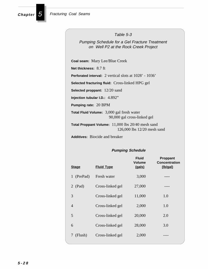
Fracturing Coal SeamsChapter 5
5 - 2 8
Table 5-3
Pumping Schedule for a Gel Fracture Treatmenton Well P2 at the Rock Creek Project
Coal seam: Mary Lee/Blue Creek
Net thickness: 8.7 ft
Perforated interval: 2 vertical slots at 1028’ - 1036’
Selected fracturing fluid: Cross-linked HPG gel
Selected proppant: 12/20 sand
Injection tubular I.D.: 4.892”
Pumping rate: 20 BPM
Total Fluid Volume: 3,000 gal fresh water 90,000 gal cross-linked gel
Total Proppant Volume: 11,000 lbs 20/40 mesh sand 126,000 lbs 12/20 mesh sand
Additives: Biocide and breaker
Pumping Schedule
Fluid Proppant Volume Concentration
Stage Fluid Type (gals) (lb/gal)
1 (PrePad) Fresh water 3,000 ----
2 (Pad) Cross-linked gel 27,000 ----
3 Cross-linked gel 11,000 1.0
4 Cross-linked gel 2,000 1.0
5 Cross-linked gel 20,000 2.0
6 Cross-linked gel 28,000 3.0
7 (Flush) Cross-linked gel 2,000 ----
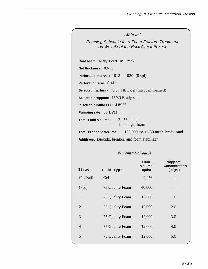
Planning a Fracture Treatment Design
Coal seam: Mary Lee/Blue Creek
Net thickness: 8.6 ft
Perforated interval: 1012’ - 1020’ (8 spf)
Perforation size: 0.41”
Selected fracturing fluid: HEC gel (nitrogen foamed)
Selected proppant: 16/30 Brady sand
Injection tubular I.D.: 4.892”
Pumping rate: 35 BPM
Total Fluid Volume: 2,456 gal gel100,00 gal foam
Total Proppant Volume: 180,000 lbs 16/30 mesh Brady sand
Additives: Biocide, breaker, and foam stabilizer
Pumping Schedule
Table 5-4
Pumping Schedule for a Foam Fracture Treatmenton Well P3 at the Rock Creek Project
(PrePad) Gel 2,456 ----
(Pad) 75 Quality Foam 40,000 ----
1 75 Quality Foam 12,000 1.0
2 75 Quality Foam 12,000 2.0
3 75 Quality Foam 12,000 3.0
4 75 Quality Foam 12,000 4.0
5 75 Quality Foam 12,000 5.0
S t a g e Fluid Type
Fluid Proppant Volume Concentration (gals) (lb/gal)
5 - 2 9
Fracturing Coal SeamsChapter 5
5 - 3
-
The success of a fracture treatment depends greatly on the suitabil-ity and quality of the materials and equipment used on the job.Maintaining strict quality control is the responsibility of theoperator’s representative at the well site. Because quality is largelya function of attitude, service companies usually provide the levelof quality that the operator demands. Therefore, before beginninga fracture treatment, you should follow several important opera-tional and quality control guidelines.This section provides the most important guidelines to use:
• When Drilling and Completing the Well
• The Week Before the Fracturing Job
• The Day of the Fracturing Job
In addition to the quality control guidelines presented in thissection, there are many other practices that may improve yourfracture treatment. For a step-by-step quality control and jobsupervision checklist that you can use on the job, refer to AppendixB.
Preparing for a Fracture Treatment
When Drilling and Completing the WellYou can take several steps when drilling and completing the wellthat will increase the possibility of an effective fracture stimulation.Success in fracturing a single coal seam generally depends on avoiding horizontal fractures and multiple fractures.
In shallow coalbeds, you cannot avoid creating horizontal fractures.Below the shallow coalbeds, you may encounter coalbeds that willfracture both horizontally and vertically. In this transition zone, youmay be able to control fracture geometry with treatment pressure.High pressure treatments in the transition zone may create complexor T-shaped fractures. Lower pressure treatments tend to propagatevertical fractures. In the deepest coalbeds, fractures will normally bevertical. The depths at which horizontal, vertical, and a combinationof horizontal and vertical fractures propagate depend on the me-chanical characteristics of the particular coal.
0
e
,
t
Preparing for a FractureTreatment
Horizontal fractures are less effective than vertical fractures becausthe drainage area affected with a horizontal fracture is considerablyless per gallon of fluid injected than with a vertical fracture. Inaddition, the probability of a screenout, or unsuccessful fracture jobis much greater with horizontal fractures. Mineback observationshave shown that a well with horizontal fractures may produce at anacceptable rate early in its life, but its production rate will declinedramatically as the area penetrated by the fracture depletes.
Multiple fractures in a well can cause high treating pressures andscreenouts. These problems make it difficult to achieve the fracturelength needed to yield adequate production rates and an effectiveradius of drainage in the reservoir.
To minimize the possibility of multiple fractures, excessive treatingpressures, and screenouts, GRI-sponsored research has shown thathe guidelines below should be followed when drilling and com-pleting the well.
■ Avoid excessive wellbore diameter, whether resulting fromdrilled hole size, borehole washout, or wellbore caving.Minimize production tests prior to fracturing because they cancause sloughing and caving. If you are required to prove thatfracturing is necessary by performing high pressure drawdownproduction testing, you may create borehole conditions thatjeopardize your opportunity to successfully fracture the well.
■ When completing the well, consider creating verticalnotches adjacent from the coal seam using a jetting tool.For open hole completions, create notches with a shortjetting operation.
When creating jetted notches, avoid creating an excessivewellbore diameter. Improperly using a jetting tool caneliminate the benefits of notching.
In open hole completions, fractures tend to initiate at the bottomof the casing.
▲▲▲▲▲ Caution
▲▲▲▲▲ Caution
Avoiding Horizontal Fractures, Multiple Fractures, and Screenouts
5 - 3 1
Fracturing Coal SeamsChapter 5
5 - 3 2
■ Drill at least 100 to 200 feet below the deepest target coalbedto provide an adequate sump for fracturing and productionoperations.An adequate sump could help prevent a screenout when pumpingthe fracture treatment. An adequate sump can also allow thepump to be placed below the perforations, which is beneficial forproduction. For more information on the sump, refer toPumping Equipment in Chapter 6.
The guidelines below are based on a GRI-sponsored statisticalanalysis of data from commercial fields in the Black Warrior Basin.Though these guidelines may apply to coalbed methane wells insome areas, data from the Rock Creek project (which is a controlledresearch site) indicates that minimizing the time between exposingthe coal (by perforating or slotting) and stimulation may not benecessary.
■ Perform the fracturing treatment soon after the coal isexposed.In many coal seams, the mechanical condition of the coalexposed in the wellbore will degenerate with time.
■ If significant time (several weeks or months) will passbefore the well is fractured, run casing soon after the well isdrilled but do not perforate or slot the casing until ready tofracture the well.Casing will minimize degeneration of the coal.
■ If significant time has passed since a well was drilled (andcasing was not set), you may attempt to use a jetting tool toremove the degenerated coal and expose fresh coal surfacesjust before fracturing.When performing this procedure, avoid creating an excessivewellbore diameter. Carefully monitor surface returns whilejetting to maximize cleanup of the coal face and minimizeenlargement of the borehole.
■ Finalize the fracture treatment design with the servicecompany.Discuss any specific equipment needed to connect the wellhead
Follow these guidelines at least a week before the fracturing treatment:The Week Before the Fracturing Job
❈❈❈❈❈ Important
-
-
e
idsns
Preparing for a FractureTreatment
to the fracturing equipment. Make sure the service companyrepresentatives know what type of wellhead connections theymust tie into.
Review your objectives for the treatment, including cost limitations and the use of standby equipment. Clarify what equip-ment and materials you (the operator) will provide and whatthings the service company will provide.
Review the quality control procedures for the treatment, anddetermine who will be responsible for performing and docu-menting them.
Designate a company representative who is responsible forsupervising the treatment in the field. Make sure sure thisperson is informed of all objectives, decisions, and conditionsregarding the job. Confirm that the service company representative is informed of these items, as well.
■ Estimate the total cost of the fracture treatment.In addition to the cost to pump the treatment, be sure to includany associated costs such as workover rig, frac tanks, waterhauling, logging, etc.
■ Make sure you know what type of fluid, crosslinker andbreaker (oxidizer or enzyme) you will use with the gelsystem.Service companies may keep some information about their fluadditives proprietary. However, to ensure the proper additiveare used, you should at least know the answers to the questiobelow:
❖ What type of crosslinker will be used (i.e., titanium, zirco-nium, borate, etc.)?
❖ How does the crosslinker work (delayed, adjustable de-layed, or instantaneous)?
❖ How does the pH of the fluid affects its performance char-acteristics?
5 - 3 3

Fracturing Coal SeamsChapter 5
5 - 3 4
❖ What type of breaker will be used (i.e., enzyme oroxydizing)?
❖ What is the breaker schedule?
❖ What tests will be performed on site to ensure the correctamount of breaker is used?
■■■■■ Make sure you know any potential adverse effects of thefracturing fluid you plan to use.You can check published data on the compatibility of fracturingfluids with coal.
■ Coordinate the logistics of moving equipment to the well site.
■ Make sure the service company brings backup pumpingunits.
■ Make sure the service company thoroughly cleans the fractanks before filling them with fluids.
■ Consider using a computerized fracture van at the welllocation to monitor the treatment and to record data.A van properly equipped with monitoring equipment provides aneffective environment for making informed decisions during thefracture job.
The Day Before the Fracturing JobSeveral hours to one day before the fracturing treatment, follow theseguidelines:
■ Sieve the fracturing sand to make sure it is properly sorted(correctly sized). If the sand is not properly sorted, theconductivity of the proppant pack will be reduced.Collect samples of the sand when the sand storage bins on locationare being loaded (usually the day before the job). Obtain thesamples according to API recommended procedures for collectingsand samples.
Performing a FractureTreatment
If you are using a crosslinked gel fracture fluid:
■ Test the gel fluid to make sure it will mix, crosslink, and breakat reservoir temperature.
If you have not read the previous section, Preparing for a FractureTreatment, you should do so before beginning the fracturing job.Once the job begins, you will not have sufficient time to stop the joband decide how to solve a pumping problem.
After the service company has placed and connected the fracturingequipment and you have reviewed the fracture treatment plan withall personnel at the well site, you are ready to begin pumping thefracture treatment.
■■■■■ Measure the pH of the gel fluid.The pH must be correct for the fluid crosslinkers and breakers towork properly. If the pH is not correctly matched, the gel fluid maybreak too quickly or not at all.
■ Measure the viscosity of the gel fluid.The viscosity must be correct for the fluid to carry the proppanteffectively into the fractures.
Several hours to one day before the fracturing job, meet with alloperating personnel and service company personnel and discuss:
❖ The specific objectives of the fracturing stimulation
❖ The pumping schedule for the stimulation
❖ The type of data wanted from the service company and theform in which you want it
❖ Contingency plans in case of operational problems or emer-gency situations
❖ Safety and environmental precautions and procedures
❖ Any questions or concerns that the personnel may have
Performing a Fracture Treatment
5 - 3 5

Fracturing Coal SeamsChapter 5
5 - 3 6
Pumping an acid treatment to open perforations or slotsmay permanently damage the permeability of the coal ifthe appropriate acid is not used. Recent GRI-sponsoredresearch suggests that some acids may react with coal tocause changes in the surface tension of the coal, resulting
Pumping the Treatment
2. While carefully monitoring the surface pressure, slowlyincrease the pump rate until the pressure drops sharply,indicating the formation has broken down.
3. Record the formation breakdown pressure.Breakdown pressure can give an indication whether perfora-tions are open.
◆ If the breakdown pressure is excessive (i.e., approachinghorsepower limits of the pumps or the burst strength of thesurface equipment or casing), the perforations or slots maybe plugged. To correct this problem, you may try one ofthese options:
A. If you can achieve a sustained, but low injection rate,mix 1/2 lb/gal sand slurry and pump in at a slightlyincreased pump-in rate to attempt to erode away anymaterial that may be plugging perforations or slots.
B. Spot 15% HCl acid across the perforations with thetubing and try again to break down the formation. Ifyou don’t have a rig on the well and cannot spot theacid with tubing, you might use a wireline dump bailerto spot the acid.
C. Re-perforate or re-slot the casing. You may considerkeeping a wireline truck and crew on standby for thispurpose.
1. Establish an initial pump-in rate by pumping into the wellat the lowest possible rate the equipment will allow (e.g., 1/4 BPM).
Based on experience at the Rock Creek project, the proceduresbelow have proven effective for pumping fracture treatments:
▲▲▲▲▲ Caution
Performing a Fracture Treatment
in the coal retaining water. Some acids may be moredamaging than others. 15% HCl has been found effectivefor fracture treatments. If acid is needed to clean perfora-tions, use it sparingly.
4. Start pumping the pad (fracturing fluid without proppant)slowly, then gradually increase the pump rate to the treat-ing rate (e.g., 15-40 Bbl/min.)This step propagates and/or widens fractures and prepares themto accept the proppant-laden slurry. A typical pad is sized at20-40% of the total fracture fluid volume. Most operatorspump a large pad to ensure they can place all of the sand slurrythey have mixed. However, pumping a large pad may notalways be necessary and it could actually limit the amount ofsand placed before screenout.
Some operators believe that if you pump the sand slurry with-out first pumping a pad (i.e., before the fracture is openedsufficiently), the sand may bridge off at the entrance or tip ofthe fracture (referred to as “tip plugging”) and cause ascreenout or cause the treating pressure to increase beyond thesafe limits of the surface equipment or casing. Other operatorsfeel that if the quality of the fluids pumped meets the designstandards, little or no pad is needed.
5. To record an instantaneous shut-in pressure (ISIP) for usein verifying formation fracture gradient, shut-in the wellafter establishing a stabilized injection rate.For more information about formation fracture gradient, referto Planning a Fracture Treatment Design earlier in this chapter.
For foam fracture treatments, shutting in to record anISIP may be impractical because it will likely make itdifficult to maintain the quality of the foam at designspecifications.
6. Slowly begin adding sand to the fracturing fluid. Start at alow concentration of about 1 lb/gal.
7. Gradually increase proppant concentration until you reachthe designed slurry concentration.
❈❈❈❈❈ Important
5 - 3 7
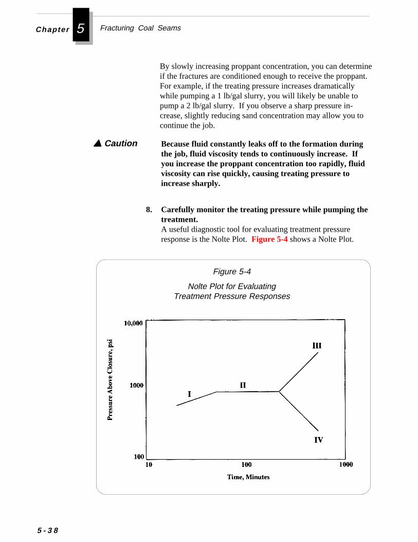
Fracturing Coal SeamsChapter 5
inet.
5 - 3 8
By slowly increasing proppant concentration, you can determif the fractures are conditioned enough to receive the proppanFor example, if the treating pressure increases dramaticallywhile pumping a 1 lb/gal slurry, you will likely be unable topump a 2 lb/gal slurry. If you observe a sharp pressure in-crease, slightly reducing sand concentration may allow you tocontinue the job.
Because fluid constantly leaks off to the formation duringthe job, fluid viscosity tends to continuously increase. Ifyou increase the proppant concentration too rapidly, fluidviscosity can rise quickly, causing treating pressure to
▲▲▲▲▲ Caution
increase sharply.
8. Carefully monitor the treating pressure while pumping thetreatment.A useful diagnostic tool for evaluating treatment pressureresponse is the Nolte Plot. Figure 5-4 shows a Nolte Plot.
Figure 5-4
Nolte Plot for EvaluatingTreatment Pressure Responses
rn
l
Performing a Fracture Treatment
Each of the “modes” in the Nolte Plot is explained below:
Mode I: Small Positive SlopeA small positive pressure increase indicates increasing fracturelength with confined height growth. This response is desirable.
Mode II: Constant PressureA constant pressure mode is potentially the most significant portionof the curve. The constant pressure mode is almost always fol-lowed by a sharp increase or decrease in pressure and never a retuto the preferable Mode I (increasing fracture length with confinedheight).
The cause of the constant pressure region (Mode II) can usually beinferred by interpreting the pressure behavior following the con-stant pressure region in Modes III and IV.
Mode III: Steep Positive SlopeWhen Mode II is followed by a steep pressure increase, the causecould be one of the following:
❖ Tip plugging (plugging of the entrance or tip of the fracturenear the wellbore)
❖ Bridging off of sand inside the fracture
❖ Leakoff of fluid to the formation
❖ Settling or “duning” of sand in the wellbore
The pressure trends indicated in the Nolte Plot are formationtreating pressures (downhole pressures). If you are measuring andanalyzing surface pressures only (not downhole pressures), severafactors could affect the surface pressures without necessarilyaffecting the formation treating pressures:
❖ Changing hydrostatic pressure of the fracturing fluid as thesand concentration increases
❖ Decreasing perforation friction pressure as the sand erodesthe perforations during the treatment
5 - 3 9
Fracturing Coal SeamsChapter 5
5 - 4 0
Because both of these situations decrease the surface treatingpressure, they could offset and mask increases in formation treat-ing pressures during Mode III. These conditions might also easilybe confused with decreasing formation treating pressure associatedwith Mode IV.
To assess the effects of hydrostatic pressure, you can run downholepressure gauges with a surface readout or a tubing “dead string.”Refer to Using a Tubing “Dead String" to Measure BottomholePressure, earlier in this chapter.
Mode IV: Negative SlopeWhen Mode II is followed by a decrease in pressure, the most likelycause is fracture height growth. Because the goal of fracturing is topropagate a fracture out laterally from the wellbore, this response isundesirable.
◆ If you observe a negative slope, you may try to reduce injectionrate to minimize fracture height growth.
9. If the estimated formation treating pressure increases as youincrease the proppant concentration, you have three options:
B. Cut sand concentration, then pump a pad (fluid withoutsand). If the treating pressure decreases, graduallyincrease sand concentration and continue the job.Some operators believe that during the fracture job, sand cansettle and accumulate or “dune” near the wellbore. Theyprefer to pump a pad to attempt to clear the dune away andthereby lower the treating pressure.
A. Increase the pump rate by about 20% and continuepumping the slurry at the same sand concentration untilscreenout.Increasing the pump rate may widen the fractures enough toaccept the fracture fluid. Some operators believe that youhave only a certain amount of time, or “window of opportu-nity,” within which to pump the slurry before screenoutoccurs. They prefer to continue pumping to place all theproppant they can before screenout.
-
Performing a Fracture Treatment
10. A sharp, sudden increase in treating pressure before theend of the job evidences a wellbore screenout or severebridging and plugging of sand in the wellbore. If youencounter a wellbore screenout, you should never try tocontinue pumping the sand slurry away. Continuing topump will result in excessive pump pressure and may crushthe sand in the near-wellbore fracture.
◆ If you encounter a wellbore screenout while pumping a gelor foamed gel treatment, shut down the pumps and stop thetreatment. You will likely have to wash the sand out of thewellbore using tubing. However, you may first try to flowback the well using one of the flowback methods describedlater in this chapter.
◆ If you encounter a wellbore screenout while pumping a waterfracture treatment, you may try the procedure below to re-establish the treating rate:
1. Shut down pumps and free flow the well back to thesurface pit until you get bottoms-up.
2. Monitor the “blooey” (return) line for dirty fluid and/orfluid with a high concentration of sand.
3. Pump clean fluid (without proppant) while graduallyincreasing the pump rate.
4. If you can re-establish the treating rate, start pumpingsand again.
5. If you cannot re-establish the treating rate, repeat thisprocedure.
6. If you have pumped two-thirds or more of the treatment,and you cannot re-establish a treating rate, you may wantto consider the job completed.
C. If the end of the job is near, increase the pump rate andcontinue pumping the fluid at a higher sand concentra-tion until the entire treatment is pumped or screenoutoccurs.Some operators increase sand concentration while continuing to pump at increased rate to try to maximize the amountof proppant they place before screenout occurs.
▲▲▲▲▲ Caution
5 - 4 1
Fracturing Coal SeamsChapter 5
5 - 4 2
The procedure above may not be useful for gel fracturetreatments. Because water has a lower viscosity and proppanttransport capability than gels, it is possible that “dunes” ofsand may develop in the fracture during a water fracturetreatment. These dunes may become immobile, which cancause increased treating pressures and wellbore screenout.Backflowing the well, as described above, may help to movethe dune enough to allow pumping the treatment again.Because gels have greater viscosity and better proppanttransport capabilities than water, sand duning is not as likelyduring a gel treatment. Therefore the procedure aboveprobably would not be as effective for a gel frac treatment.
11. Do not over-flush the wellbore after pumping the fracturetreatment.Over-flushing means pumping clean fluid (without proppant)in an attempt to displace into the fractures any sand-ladenfluid remaining in the wellbore once pumping is completed.Some operators over-flush to try to eliminate production ofsand after the fracture treatment. However, over-flushing hasnot been demonstrated to control sand production.
Over-flushing may wash away some of the near-wellboresand pack. When treating pressure is released, theunpropped fractures near the wellbore may close andthus severely restrict production.
12. Near the end of the job, observe and record these pres-sures at the surface to help in the design of future fracturetreatments:
• Final treating pressure before shutting down pumps.
• Initial Shut-in Pressure (ISIP) at surface as soon as thepumps shut down.
• Pressure fall-off after shut-in.Look for an inflection point, or sharp change, in the rate ofpressure decline. This inflection indicates the “closurepressure,” or pressure at which the fracture closes on theproppant.
▲▲▲▲▲ Caution
Performing a FractureTreatment
Flowing Back the Well After the TreatmentAs with most aspects of fracturing coalbed methane wells, theselection of a method for flowing the well back is generally contro-versial. There are many divergent opinions about the most effec-tive flowback technique. Three of the most common opinions arelisted below:
❖ Fractured wells should be flowed back at a slow rate imme-diately after the treatment to force the formation to close onthe proppant before the gel breaks. This method is called“forced closure.” If the fracture does not close on theproppant before the gel breaks, the sand may settle to thebottom of the fracture. If the fracture extended below thecoal seam, such sand settling could result in an unproppedfracture in the coal.“New Techniques and Quality Control Find Success inEnhancing Productivity and Minimizing ProppantFlowback, ” J.W. Ely et al, SPE Paper 20708, SPE AnnualTechnical Conference and Exhibition, 1990.
❖ Flowing back wells immediately after the fracture treatmentwill not prevent sand from settling in the fracture. Becauseflowing back the well only affects a small region near thewellbore, it will not prevent sand from settling in a fractureaway from the wellbore. Moreover, as the treating pressureof the shut-in well leaks off to the formation naturally, thefluid flows through the proppant pack at a rate greater thancould be achieved by flowing back the well.
As fracture fluid leaks off into the formation, pressure inthe fracture decreases. Eventually, the pressure declinesenough to allow the fracture to close on the proppant.
When the fracture closes, the fluid can only flow throughthe proppant pack, which creates increased frictionalpressure loss. Therefore, the decreased rate of pressuredecline you observe at the surface reflects the closure ofthe propped fracture.
5 - 4 3

Fracturing Coal SeamsChapter 5
5 - 4 4
fracture closes on the proppant (fracture closure) so thatpressures can be monitored. Monitoring pressures after thewell is shut-in will help you to determine how quickly thefracture closes on the proppant and the pressure at whichclosure occurs. (Closure pressure is the fluid pressurerequired to initiate the opening of an existing fracture. Thispressure is equal to and counteracts the stress in the rockperpendicular to the fracture plane. This stress, oftencalled closure stress, is the minimum principal in-situstress. Closure pressure is indicated by an inflection point,or sharp change, in the rate of pressure decline after thewell is shut-in.)“Experimental and Modeling Evidence for MajorChanges in Hydraulic Fracturing Design and FieldProcedures,” M.P. Cleary et al, SPE Paper 21494, SPEGas Technology Symposium, 1991.
❖ Fractured wells should not be flowed back until the fractur-ing gel breaks. Prematurely flowing back unbroken gelmay flush proppant out of the fracture at the wellbore andresult in poor conductivity near the wellbore, where it ismost needed.“Recent Advances in Hydraulic Fracturing,” SPE Mono-graph Vol. 12, J.L. Gidley et al, 1989.
A theoretical discussion of these varying opinions is beyond thescope of this guide. However, you may want to investigate each ofthem further to help you determine the best flowback method foryour particular application.
Most operators in the Black Warrior Basin generally use one ofthree methods (or a variation of these methods) to flow back wellsafter a fracture stimulation. These methods are:
• Shut-In with Slow Flowback
• Forced Closure Through Flowback
• High Rate Flowback
• Foam Treatment Flowback
rel
the
t-
ngo
obn
lesak
t
re
e
Performing a FractureTreatment
In this method, you shut in the well for a period of time followingthe treatment and then flow back the well at a slow rate. Someoperators believe this method is effective because it allows greaterecovery of the gel fracturing fluid. The shut-in period gives the gsufficient time to break. As the gel degrades with time, it flowsmore easily through the sand pack and into the wellbore. Otheroperators like this method because they believe it allows time for fracture to close on the proppant, thus providing a well proppedfracture.
Some operators dislike the slow flowback method because theybelieve it allows time for the proppant to settle in the fracture andthus allows the top portion of fracture to close without proppant init.
The length of the shut-in period depends on your purpose for shuting in the well. If you use the shut-in period to allow the gel timeto break, you can estimate the time for gel breakdown by consultiwith the service company pumping the treatment. You should alswatch the gel samples that were collected throughout the job andmake sure at least the gel pumped during the later stages of the jdid break. If there is a significant temperature difference betweethe surface and bottomhole (i.e., the coal seam is deep), the gel inthe formation may break before the gel sample on the surface. Insome cases, the gel sample may not break at all. If the gel sampdo not break, you can accept the service company’s estimated bretime and then monitor the fluid that is flowed back to see if it ap-pears to be gel or broken gel.
If you use this flowback method to allow time for the fracture toclose on the proppant, you should closely monitor well pressuresafter the fracture treatment and try to identify fracture closure as ioccurs. It is not possible to accurately predict closure pressure inadvance of the treatment. Moreover, the closure pressure forcoalbed methane wells cannot be estimated accurately from closupressure data from offset wells.
At the Rock Creek project, the shut-in with slow flowback methodhas been used successfully for gel fracture treatments. Experienchas demonstrated that this method produces the most effectivefracture treatment with the fewest production problems. Becauseslow flowback effectively reduces the amount of coal fines and
Shut-In with Slow Flowback
5 - 4 5
Fracturing Coal SeamsChapter 5
5 - 4 6
fracture proppant that enters the wellbore and surface productionequipment, it reduces costly wellbore cleanouts and downholepump replacements.
The procedures used to flow back a well and place it on productionat Rock Creek are listed below:
1. After pumping the fracture treatment, shut-in the welluntil the gel breaks (usually 1/2 day to 1 day).
2. If there is still pressure on the wellhead at the end of theshut-in period, flow the well back at a slow rate.
3. Continually monitor the fluid for proppant or coal fines.If you observe proppant or fines, decrease the flow rate asneeded to stop the flowback of proppant or fines.
4. After the well has been flowed back long enough to bleedoff wellhead pressure, remove the frac valve and re-installthe wellhead.
5. Run a string of production tubing to the bottom of the wellto wash out the wellbore.
You must wash any sand and debris out of the sump so youcan place the production pump at or below the perforations tominimize bottomhole pressure and maximize flowrate.
6. Pump clean fluid down the tubing-casing annulus and takereturns up the tubing string.
7. Lower the tubing string and wash the wellbore down to thebottom of the sump.
Pumping down the tubing and taking returns up the tubing-casing annulus may cause any debris in the well to flow intoperforations or slots and plug them. You may avoid thisproblem by washing the wellbore with air instead of water.
▲▲▲▲▲ Caution
7.
p-
st
d
-
Performing a FractureTreatment
8. Install the production pump and begin pumping the welldown.For information on pumping the well down, refer to Chapter
❈❈❈❈❈ Important
Flow the well back at a restricted rate within seconds or minutesafter you finish pumping the treatment. Procedures and an equiment schematic for this method are shown in Appendix C.
Some operators believe this method allows the fracture to closemore quickly, thereby preventing proppant from settling to thebottom of the fracture and leaving the top portion unpropped.However, because of the generally poor elastic properties of moshallow coals (as compared to sandstones), fracture closure willlikely be slow and/or incomplete. Evidence suggests this methomay work best in deep, low-permeability coalbeds, which exhibitgreater elastic properties.
Flow the well back at a very high rate (i.e., little or no flow restriction) a few minutes after you finish pumping the treatment.
A few operators believe this method flows back sand that wouldotherwise flow into the wellbore when the well is produced. Theybelieve any near-wellbore voids in the proppant pack caused byflowback are filled by other sand from deeper in the fracture.
The forced closure method may cause sand to flow into thewellbore if you flow the well back at an excessive rate. Thisproppant flowback may leave near-wellbore fracturesunpropped and thus restrict production.
▲▲▲▲▲ Caution
The decision to use the Shut-In with Slow Flowback method maydepend on the type of fracture fluid used. If using a fluid with poorproppant-carrying capacity (i.e., water), sand in the fracturecould quickly settle below the pay zone causing the fracturethrough the pay zone to close. Thus, when using a fluid with poorproppant carrying capacity, you may consider using the ForcedClosure method.
Forced Closure Through Flowback
High Rate Flowback
5 - 4 7
Fracturing Coal SeamsChapter 5
5 - 4 8
ren
k
Fracturing is usually required to create a productive coalbed meth-ane well, and it can represent the single greatest cost on the well.Therefore, it is prudent to evaluate the effectiveness of each fractutreatment so the design and implementation of future treatments cabe improved.
The evaluation of a fracture treatment is usually performed by areservoir engineer. For information on the reservoir engineeringaspects of fracture evaluation, refer to Additional Resources at theend of this chapter.
This section provides an overview of the field aspects of fractureevaluation. The techniques that have been used at the Rock Creeproject to evaluate the success of hydraulic fracture treatments are
• Production Comparison
• Pressure Transient Well Tests
Evaluating a Fracture Treatment
One of the advantages of using a foamed fluid is quick clean-up.Because foamed fracturing fluids contain 65-85% gas (usuallynitrogen), less liquid must be flowed back after a foam fracturingtreatment. Therefore, most operators start flowing back the foamtreatment as soon as possible after the end of the treatment.
At the Rock Creek project, as soon as the service company equip-ment is rigged down from the wellhead, a flowline to the produc-tion pit or frac tank is rigged up and flowback begins. As with gelfracture treatments, the flowback rate is restricted to preventproppant flowback into the wellbore.
The high rate flowback method may damage the fracturetreatment by pulling sand out of the fracture. This proppantflowback may leave near-wellbore fractures unpropped andthus restrict production. This method is not recommended.
▲▲▲▲▲ Caution
Foam Treatment Flowback
Evaluating a FractureTreatment
n
re
n
e
e
d
-
In some conventional gas fields, the simplest and most conclusiveway to evaluate a fracture treatment is to test the well before frac-turing and then compare the pre-frac production rate to the rateafter treatment. However, such production comparisons can bemisleading for coalbed methane wells.
In newly completed coalbed methane wells, pre-fracture productiotests are often unreliable indicators of the true reservoir propertiesof the coal because of poor communication with the natural fractusystem of the coal. Even though perforating or slotting may pen-etrate through the casing and cement, it is possible the penetratiointo the coal might be insufficient to penetrate the coal’s naturalfractures.
Comparisons with post-fracture production tests in offset wells canalso be misleading because of heterogeneities in the coals and thoverlying rock. The reservoir and rock properties of the coal andthe overlying rock can vary considerably over short distances.Some of the variables that may contribute to this heterogeneity arthe presence or absence of fractures in the overlying rock, stressregimes in the rock, cleat development within the coal, and thepresence of mineral filling in the cleat system.
Production comparisons may be helpful in evaluating fracturetreatments, but you should not rely greatly on them and you shoulnever use them as the only evaluation tool. If you do compareproduction from individual wells in a field, you should probablyexclude the upper and lower 5-10% of the wells (based on production rate) in order to make realistic comparisons.
At the Rock Creek project, production data is generally used assupport information in evaluating fracture treatments. Fracturetreatment evaluations are based primarily on well tests and datafrom monitor wells.
Production Comparison
• Response in Offset Wells
• Radioactive Tracers/Gamma Ray Log
• Tiltmeters
5 - 4 9
Fracturing Coal SeamsChapter 5
te
r-r-
testsion
nt-d
re
be
t
5 - 5 0
Pressure Transient Well TestsPost-fracture pressure transient well tests can help you to evaluathe success of fracture treatments by helping you determine theeffective length and conductivity of the created fracture. To esti-mate the effective fracture length, you usually must know the aveage permeability of the formation before the fracture job. To detemine the permeability, you must conduct a pre-fracture pressuretransient well test.
The procedures used to conduct post-fracture pressure transient are the same as those used on non-fractured wells. For informaton performing pressure transient well tests, refer to Chapter 9.
The techniques for analyzing well tests of fractured wells is differethan those used for non-fractured wells. Analysis of pressure transient tests is beyond the scope of this guide; however, you can fininformation on this topic in Additional Resources at the end ofChapter 9.
Response in Offset WellsBy monitoring the production and pressure responses in nearbyoffset wells, you may gain information useful in determining thedirection of the induced fracture. Responses in offset wells mayalso be incorporated into a reservoir simulation to estimate fractuheight and length.
In some coalbed methane fields, the distance between wells maytoo great to detect pressure responses to a fracture treatment inoffset wells. However, you may be able to gain useful informationby monitoring the closest offset wells for changes in reservoirpressures and produced fluid characteristics. Such changes mayhelp you determine communication with fractured coal intervalsand the orientation of the induced fracture.
The least expensive way to measure pressure responses in offsewells is by shooting acoustic fluid levels. However, the accuracyof measuring the fluid level is only approximately the length of ajoint of tubing, or about 30 feet. Thus, you can not detect smallpressure responses with this method.

y
f
n-
ymaed
le If a
,s
tti-to
ge
d
Evaluating a FractureTreatment
To detect pressure changes with greater accuracy, you can rundownhole pressure sensors in offset wells. Pressure sensors maprovide accurate and useful data, but their rental cost may bedifficult to justify. If you do use pressure sensors, try to take fulladvantage of them. For example, you can schedule a well testwhile the sensor is installed in the well to gain additional use from
Radioactive tracers can be used with the gamma ray log to helpdetermine the height of the induced fracture and the placement othe fracture treatment. However, some service companies nolonger provide the radioactive tracer service because of the potetial health risks to their workers. Because you might have diffi-culty in locating a company to provide the service, you shouldcheck with service companies well in advance of the fracture job.
In this technique, radioactive tracers are placed in the fracturingsand and/or fluid while it is pumped. Then after the stimulatedwell has been flowed back, a gamma ray log is run in the well. Bcomparing the post-fracture gamma ray log to a base log (a gamray log run before the fracture treatment), the effects of the injectfracturing fluids may be determined.
The gamma ray log usually run in combination with the cased hocement evaluation log is often used as the base gamma ray log. cased hole gamma ray log was not run before the treatment, youneed not run make a special logging run. You can use the openhole gamma ray log as the base log.
To help you correctly distinguish fracture height from fluid leakoffyou can place different radioactive isotopes in the different stageof the fracture treatment. For example, you can run differentisotopes in the pad, the first proppant stage, and the last proppanstage. A special gamma ray detector can be run that will differenate between the different isotopes. This technique will allow you distinguish between propped fracture height and fluid channelingbehind pipe. It may also help you determine whether the nearwellbore fracture is propped with the first stage sand, the last stasand, or a mixture of the two.
You should wait until the well has been flowed back and producefor a while before running the gamma ray log. This period of time
the pressure data.
Radioactive Tracers/Gamma Ray Log
5 - 5 1

Fracturing Coal SeamsChapter 5
u
l.
5 - 5 2
will help to eliminate traces of the radioactive isotopes in thewellbore and thus reduce the possibility of making erroneous loginterpretations. However, each isotope has a specific half-life. Yomust run the log before the shortest half-life of any of the isotopesexpires so the gamma ray log will still detect the radioactivity.
Using radioactive tracers may not always help you determineactual fracture height because tracers have a limited detectiondepth and because the fracture may not be in line with thewellbore.
When planning to use radioactive tracers to evaluate a fracturetreatment, consider the guidelines below:
■■■■■ Determine the types of information you want to obtain byusing tracers. Discuss the evaluation with the reservoirengineer for the project.For example, will it be helpful to know where the fluids wentor which proppant stage propped the near wellbore fracture?
■■■■■ Consult with a service company that will perform thefracture treatment to determine its capabilities and toobtain its recommendation for using radioactive tracers.
■■■■■ Make sure that either a cased hole or open hole gamma raylog has been run on the well before the fracture treatment.
■■■■■ Check with local regulatory agencies to learn about theirpolicies for using radioactive tracers.More than one agency may regulate radioactive substances.Agencies in some states will not allow the use of radioactivetracers in shallow seams.
❈❈❈❈❈ Important
Tiltmeters are sensitive geophysical instruments that are used tomeasure slight displacements in the earth’s surface from horizonta
Tiltmeters
A tiltmeter is essentially a bubble level. The primary component inthe tiltmeter is the tilt sensor, shown in Figure 5-5. The tilt sensorcontains a receptacle filled with two fluids. Each fluid has a
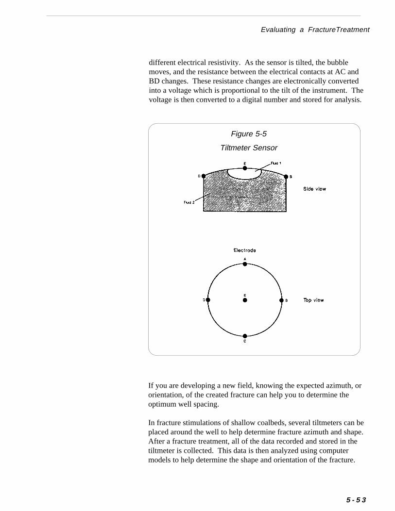
.
Evaluating a FractureTreatment
different electrical resistivity. As the sensor is tilted, the bubblemoves, and the resistance between the electrical contacts at AC andBD changes. These resistance changes are electronically convertedinto a voltage which is proportional to the tilt of the instrument. Thevoltage is then converted to a digital number and stored for analysis
Figure 5-5
Tiltmeter Sensor
ee.
If you are developing a new field, knowing the expected azimuth, ororientation, of the created fracture can help you to determine theoptimum well spacing.
In fracture stimulations of shallow coalbeds, several tiltmeters can bplaced around the well to help determine fracture azimuth and shapAfter a fracture treatment, all of the data recorded and stored in thetiltmeter is collected. This data is then analyzed using computermodels to help determine the shape and orientation of the fracture.
5 - 5 3
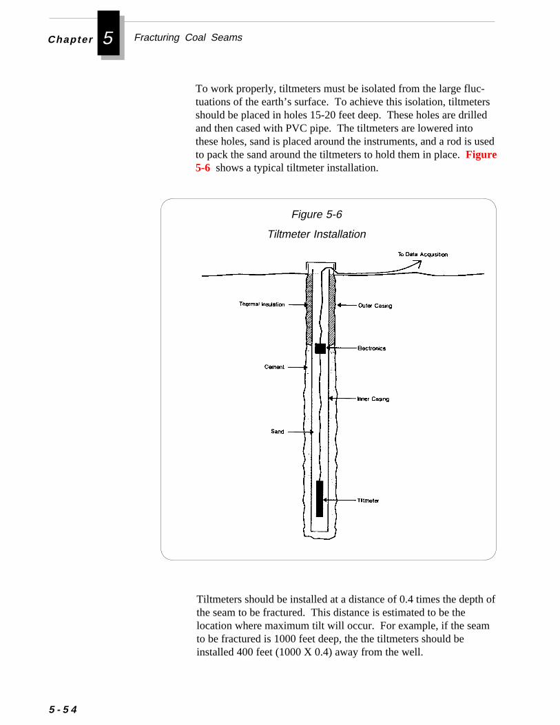
Fracturing Coal SeamsChapter 5
rsled
used
5 - 5 4
To work properly, tiltmeters must be isolated from the large fluc-tuations of the earth’s surface. To achieve this isolation, tiltmeteshould be placed in holes 15-20 feet deep. These holes are driland then cased with PVC pipe. The tiltmeters are lowered intothese holes, sand is placed around the instruments, and a rod isto pack the sand around the tiltmeters to hold them in place. Figure5-6 shows a typical tiltmeter installation.
Figure 5-6
Tiltmeter Installation
of
Tiltmeters should be installed at a distance of 0.4 times the depth the seam to be fractured. This distance is estimated to be thelocation where maximum tilt will occur. For example, if the seamto be fractured is 1000 feet deep, the the tiltmeters should beinstalled 400 feet (1000 X 0.4) away from the well.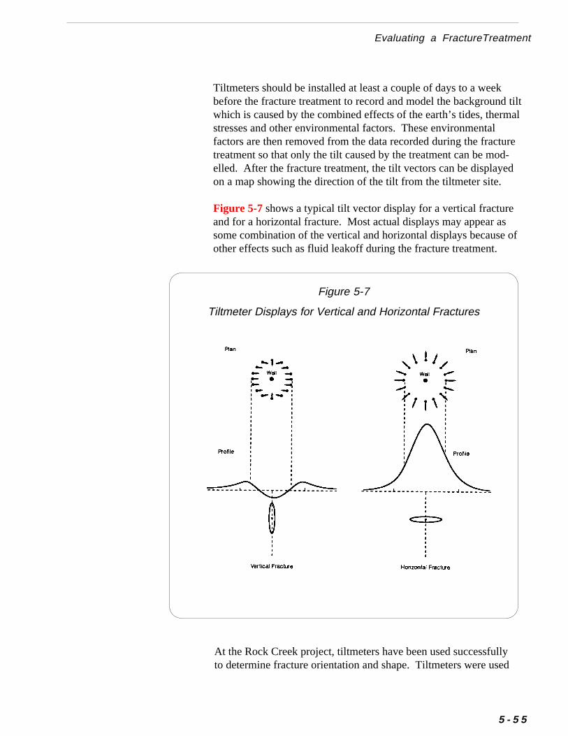
d tiltrmal
ured-ed
s of
Evaluating a FractureTreatment
Tiltmeters should be installed at least a couple of days to a weekbefore the fracture treatment to record and model the backgrounwhich is caused by the combined effects of the earth’s tides, thestresses and other environmental factors. These environmentalfactors are then removed from the data recorded during the fracttreatment so that only the tilt caused by the treatment can be moelled. After the fracture treatment, the tilt vectors can be displayon a map showing the direction of the tilt from the tiltmeter site.
Figure 5-7 shows a typical tilt vector display for a vertical fractureand for a horizontal fracture. Most actual displays may appear asome combination of the vertical and horizontal displays becauseother effects such as fluid leakoff during the fracture treatment.
Figure 5-7
Tiltmeter Displays for Vertical and Horizontal Fractures
ullysed
At the Rock Creek project, tiltmeters have been used successfto determine fracture orientation and shape. Tiltmeters were u
5 - 5 5
Fracturing Coal SeamsChapter 5
5 - 5 6
to record data when Wells P1A, P1B, P1C, and P4 were fractured.Analysis of the data for Well P1A indicated the Pratt coalseam (at478 feet) was fractured horizontally. Analysis of data for WellsP1B and P1A indicated the Mary Lee/Blue Creek coalseams (1039feet) and the Black Creek coalseam (1418 feet), respectively, werefractured vertically. The fracture of the Mary Lee in Well P4 alsowas found to be vertical.
Running tiltmeters is a sensitive and expensive operation. Toobtain useful data you must carefully coordinate the fracturetreatment with the service company providing the tiltmeters. Tohelp ensure a successful job, consider the guidelines below:
■ Discuss the fracture stimulation plan and the tiltmeterinstallation requirements with the tiltmeter service repre-sentative in advance of the job.
■ Drill holes for tiltmeters at least one week before the frac-ture treatment.
■ Make sure the tiltmeters are calibrated and installed atleast two days before the fracture treatment to recordbackground trends, which are needed for the analysis.
■ Inform the tiltmeter service representative of the startingtime for the fracture treatment.
■ Avoid scheduling the fracture treatment during stormyweather. Such weather conditions can adversely affect thedata.
■ Drill the tiltmeter holes as straight as possible.
■ Make sure to include the cost of drilling tiltmeter holes inthe cost estimate for running tiltmeters.

a-
Evaluating a FractureTreatment
For more information on tiltmeters, you may consult with compnies that provide specialized geophysical services.
❖ ❖ ❖
5 - 5 7
Fracturing Coal SeamsChapter 5
5 - 5 8
).
-
-
Additional Resources
Cleary, M.P., C.A. Wright, and T.B. Wright, “Experimental andModeling Evidence for Major Changes in Hydraulic FracturingDesign and Field Procedures,” SPE Paper 21494, presented at the1991 SPE Gas Technology Symposium, Houston (January 22-24
Ely, J.W., W.T. Arnold, and S.A. Holditch, “New Techniques andQuality Control Find Success in Enhancing Productivity andMinimizing Proppant Flowback,” SPE Paper 20708 presented atthe 1990 Annual Technical Conference and Exhibition, NewOrleans (September 23-25).
Gazonas, G.A., C.A. Wright, and M.D. Wood, “Tiltmeter Map-ping and Monitoring of Hydraulic Fracture Propagation in Coal:A Case Study in the Warrior Basin, Alabama,” Geology andCoalbed Methane Resources of the Northern San Juan Basin,Colorado, New Mexico, Rocky Mountain Association of Geolo-gists, Denver, 1988.
Gidley, J.L., S.A. Holditch, D.E. Nierode, and R.W. Veatch Jr.,“Recent Advances in Hydraulic Fracturing,” SPEMonograph 12, 1989.
Holditch, S.A. et al, “Enhanced Recovery of Coalbed MethaneThrough Hydraulic Fracturing,” SPE Paper 18250 presented atthe 1988 SPE Annual Technical Conference and Exhibition, Houston (October 2-5).
Holditch, S.A. and Associates, Inc., “ Hydraulic Fracturing ofCoal Seams,” a short course presented at the 1991 Coalbed Methane Symposium, Tuscaloosa, Alabama (May 13-16).Khodaverdian M., J.D. McLennan, A.H. Jones et al, “Examinationof Near-Wellbore Effects of Hydraulic Fracturing of Coal,” inRock Mechanics as a Multidisciplinary Science, Norman, Okla-homa, 1992.
Additional Resources
Lee, W.S., “ New Method of Minifrac Analysis Offers GreaterAccuracy and Enhanced Applicability,” SPE Paper 15041 pre-sented at the 1986 Eastern Regional Meeting, Columbus, Ohio(November 12-14).
McDaniel, B.W., “Benefits and Problems of Minifrac Applica-tions in Coalbed Methane Wells,” CIM/SPE Paper 90-103 pre-sented a the the 1990 CIM/SPE International Technical Meeting,Calgary (June 10-13).
Nierode, D.E., “ Comparison of Hydraulic Fracture Design Meth-ods to Observed Field Results,” SPE Paper 12059 presented at the1983 Annual Technical Conference and Exhibition, San Francisco(October 5-8).
Nolte, K.G., “ Determination of Fracture Parameters from Frac-turing Pressure Decline,” SPE Paper 8341 presented at the 1979Annual Technical Conference and Exhibition, Las Vegas (Septem-ber 23-26).
Nolte, K.G., “ A General Analysis of Fracturing Pressure DeclineAnalysis with Application to Three Models,” SPE FormationEvaluation, December 1986.
Nolte, K.G. and Smith, M.G., “ Interpretation of FracturingPressures,” Journal of Petroleum Technology, 1981.
Palmer, I.D., R.T. Fryar, K.A. Tumino, and R. Puri, “ComparisonBetween Gel-Fracture and Water-Fracture Stimulations in theBlack Warrior Basin,” Proceedings of the 1991 Coalbed MethaneSymposium, The University of Alabama, Tuscaloosa, Alabama,(May 13-16).
Puri, R., G.E. King, and I.D. Palmer, “Damage to Coal Permeabil-ity During Hydraulic Fracturing,” Proceedings of the 1991Coalbed Methane Symposium, The University of Alabama,Tuscaloosa, Alabama (May 13-16).
5 - 5 9
Fracturing Coal SeamsChapter 5
e
5 - 6 0
Shelley, R.F. and McGowen, J.M., “ Pump-in Test CorrelationPredicts Proppant Placement,” SPE Paper 15151 presented at th1986 Rocky Mountain Regional Meeting, Billings (May 19-21).
Soliman, M.Y., R.D. Kuhlman, and D.K. Poulsen, “MinifracAnalysis for a Heterogeneous Formation,” CIM/SPE Paper90-5 presented at the 1990 CIM/SPE International TechnicalMeeting, Calgary (June 10-13).
6 Selecting Production Equipment andFacilities
-onaloryoue
erter
M uch of the well equipment and production facilities for producing a coalbed methane field is the same as that used in a conventioil or gas field. However, operating experience in the Black WarriBasin has provided many useful adaptations and improvements may find particularly effective for operating a coalbed methanproject.
This chapter provides practical guidelines to help you select propequipment and facilities for your coalbed methane field. The chapwill guide you through:
• Estimating the Volume of Water to be Produced
• Pumping Equipment
• Power Supply for Pumping Equipment
• Surface Production Facilities
• Gas Compressors
• Gas Dehydration Equipment
6 Selecting Production Equipment and FacilitiesChapter
6 - 2
,dn-teneter
ereundst
ts
anreheg
ralc-tal
Estimating the Volume of Water to be ProducedTo initiate and maintain gas flow from low-pressure coal formationsyou must continuously remove water from the well. This co-producewater is one of the biggest differences between producing convetional natural gas and producing coalbed methane. Operators ofhave to pump water from wells for six months or longer beformethane is produced. When multiple coal seams are produced, waproduction can be high.
The volume of produced water will depend on the properties of thcoal seam, which can vary greatly from one area to another. Befoyou can begin planning the equipment and facilities for a field, yomust estimate the volume of water you will need to produce, treat adispose. The volume of produced water is often one of the moimportant factors in determining equipment and facility requiremenand overall project economics.
Though you may find it difficult to estimate produced water volumein a undeveloped area, you should use the best information you cobtain. Keep in mind that water production rates observed befofracturing a well may be substantially less than water rates after twell is fractured. The guidelines below may help you in estimatinwater production data.
■■■■■ When drilling exploratory wells or development wells, you canestimate water flow from formations by closely monitoringthe drilling pits.
■■■■■ When a well has been drilled to total depth (TD), trip to TDwith drillstring (or coiled tubing), inject compressed air, airmist, or nitrogen for several hours to clean out the wellbore,and observe water production rates at the surface.
■■■■■ Obtain data from other producers in the area if it is available.Seek data about formation permeability, initial and peak waterates,and cumulative water volumes to-date for specific coformations in the area. If producers are reluctant to share prodution data, you may find this data available as public information ayour state or regional oil and gas agencies or environmentagencies.
Pumping Equipment
■■■■■ Perform hydrologic (slug) tests in exploratory wells or coreholes to estimate the permeability of the coal seam.You can make a general approximation of the water influx ratebased on this permeability estimate. For information on perform-ing slug tests, refer to Chapter 9.
Table 6-1 shows a summary of the benefits and limitations of usingthese artifical lift methods for coalbed methane wells.
To maximize gas production from a coalbed methane well, you mustkeep the water level in the wellbore below the lowest producingcoalbed. Because coalbeds are usually relatively shallow, low-pressure formations, you must pump water from coalbed wells con-tinuously (or intermittently) to minimize bottomhole pressure andallow gas to flow into the wellbore.
This section will explain the benefits and limitations of the mostcommon methods used to pump water from coalbed wells. Thesemethods are:
• Beam Pumps
• Progressing Cavity Pumps
• Gas Lift
• Electric Submersible Pumps
Pumping Equipment
6 - 3
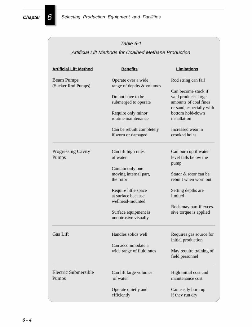
6 Selecting Production Equipment and FacilitiesChapter
6 - 4
Table 6-1
Artificial Lift Methods for Coalbed Methane Production
Artificial Lift Method Benefits Limitations
Beam Pumps Operate over a wide Rod string can fail(Sucker Rod Pumps) range of depths & volumes
Can become stuck ifDo not have to be well produces largesubmerged to operate amounts of coal fines
or sand, especially withRequire only minor bottom hold-downroutine maintenance installation
Can be rebuilt completely Increased wear inif worn or damaged crooked holes
Progressing Cavity Can lift high rates Can burn up if waterPumps of water level falls below the
pumpContain only onemoving internal part, Stator & rotor can bethe rotor rebuilt when worn out
Require little space Setting depths areat surface because limitedwellhead-mounted
Rods may part if exces-Surface equipment is sive torque is appliedunobtrusive visually
Gas Lift Handles solids well Requires gas source forinitial production
Can accommodate awide range of fluid rates May require training of
field personnel
Electric Submersible Can lift large volumes High initial cost andPumps of water maintenance cost
Operate quietly and Can easily burn upefficiently if they run dry

, a/
Pumping Equipment
Beam PumpsBeam pumps, also called sucker rod pumps, have served as aneffective, reliable, and relatively inexpensive method for removingliquids from wells since the early days of the oil industry.
The beam pumping system consists of a downhole plunger pumpsucker rod string, a surface pumping unit (pump jack), a gearboxspeed reducer and a prime mover (motor). Figure 6-1 shows atypical beam pumping system.
6 - 5
Figure 6-1
Beam Pump
6 Selecting Production Equipment and FacilitiesChapter
-dth,ed
;
mptire.ed
ter,aterer
o
lt alistsr aandor
6 - 6
For a beam pumping to operate effectively and with minimal maintenance, all components of the pumping system must be designeand sized properly. The system must accommodate the well depand the volume, viscosity, and abrasiveness of fluids to be produc(water and gas).
Beam pumps are relatively simple and durable. They require onlyminor routine maintenance. Special subsurface designs may berequired in extremely gassy wells or wells with large amounts ofsand and fines. Properly sized units can pump up to 2,500 BWPDhowever, pumping units pumping less than 600 BWPD are morecommon.
Because of the relatively shallow producing depths in the BlackWarrior Basin, operators in this area use beam pumping units withpeak torque ratings ranging from 40,000 inch-pounds to 228,000inch-pounds and stroke lengths ranging from 36 inches to 120inches.
Most operators in the Black Warrior Basin use a thin-wall (lowpressure) insert type of sucker rod pump, or plunger pump. This pusits in a seating nipple at the bottom of the tubing string, and the enpump can be retrieved by simply pulling the sucker rod stringBecause solids production requires frequent pump repairs in coalbmethane wells, this easy retrievability is a significant advantage.
Some operators use a tubing pump to pump large volumes of waespecially during initial production. The tubing pump has a barrel this installed in the tubing string. The plunger is lowered on the suckrod string and is latched into the barrel. You can retrieve the plungby pulling the rods; however, you must pull the tubing string tretrieve the barrel.
To select the best type of pump system for your operation, consutrained, experienced pump specialist. A competent pump speciawill discuss the particular requirements of your field, simulate variouproducing scenarios, and provide detailed computer analyses fovariety of possible pump designs. For example, pump specialists cexplain the benefits and limitations of combining various types ansizes of plungers, tubing, rod strings, pump jacks, and motors. Fmore information on beam pumping systems, refer to AdditionalResources the end of this chapter.
Selecting a Sucker Rod Pump and Equipment
esele
hehe
s
veing
Pumping Equipment
Operating experience in the Black Warrior Basin has produced thgeneral guidelines, which should help you in selecting downhoequipment for beam pumping units:
■ Install a tubing anchor at the bottom of the tubing string toeliminate tubing stretch.If the tubing is not anchored, the pump can pick up the weight of ttubing string on the upstroke. This weight can greatly reduce tefficiency of the pump. Tubing stretch is more pronouncedin deep wells.
■ In new wells, install a ring-type plunger pump initially. Afterthe well cleans up and stops producing appreciable amounts ofsand or coal fines, replace the ring-type pump with a metalplunger pump.Ring-type pumps contain non-metal parts which will not cut out aeasily as metal pump parts.
■ Install double standing valves and double travelling valves ineach pump.Installing two valves provides a backup in case the primary valfails. This step can reduce the cost of pulling pumps by extendthe time between pulling jobs.
an-
notand
■ In shallow, low-pressure wells, install the pump with a top-seating hold-down assembly. Figure 6-2 shows a pump installedwith a top-seating hold-down assembly.
The top-seating hold-down assembly provides these distinct advtages:
❖ Prevents the pump from becoming stuck because it does allow sand and coal fines to settle between the pump barrel the inside of tubing.
❖ The pump barrel cannot wear by rubbing against the tubingbecause the body of the pump pivots from its top and alignsin crooked holes more readily than other types of pumps.
6 - 7
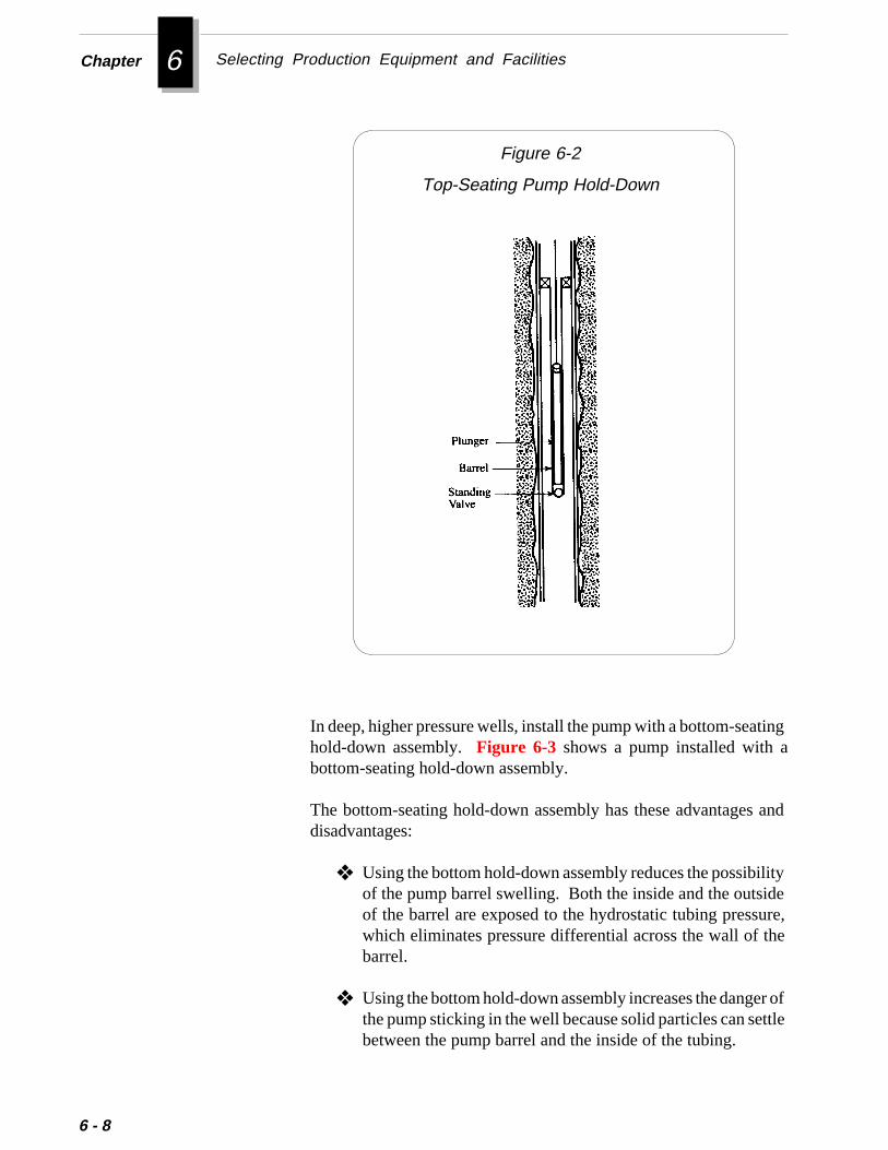
6 Selecting Production Equipment and FacilitiesChapter
ing
and
ityere,e
r ofttle
6 - 8
Figure 6-2
Top-Seating Pump Hold-Down
In deep, higher pressure wells, install the pump with a bottom-seathold-down assembly. Figure 6-3 shows a pump installed with abottom-seating hold-down assembly.
The bottom-seating hold-down assembly has these advantagesdisadvantages:
❖ Using the bottom hold-down assembly reduces the possibilof the pump barrel swelling. Both the inside and the outsidof the barrel are exposed to the hydrostatic tubing pressuwhich eliminates pressure differential across the wall of thbarrel.
❖ Using the bottom hold-down assembly increases the dangethe pump sticking in the well because solid particles can sebetween the pump barrel and the inside of the tubing.
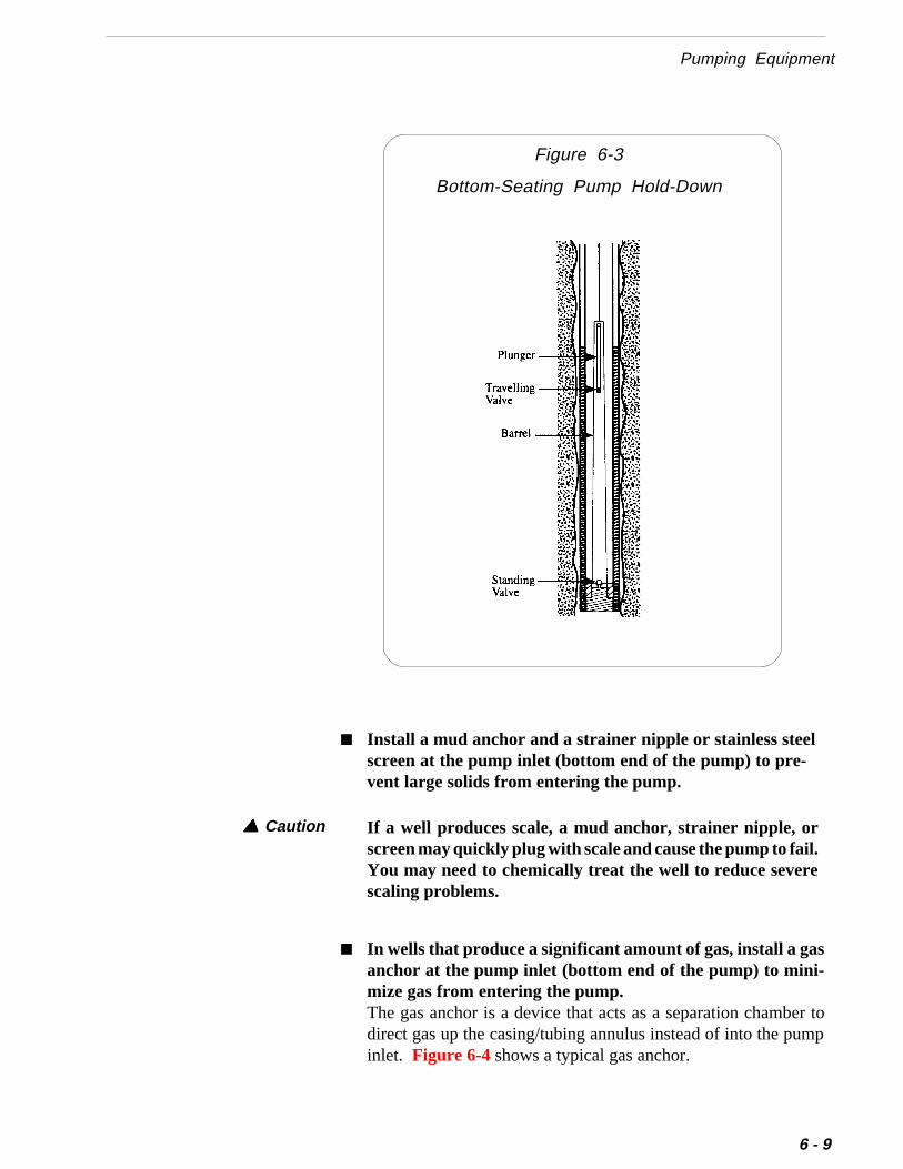
Pumping Equipment
Figure 6-3
Bottom-Seating Pump Hold-Down
■ Install a mud anchor and a strainer nipple or stainless steelscreen at the pump inlet (bottom end of the pump) to pre-vent large solids from entering the pump.
If a well produces scale, a mud anchor, strainer nipple, orscreen may quickly plug with scale and cause the pump to fail.You may need to chemically treat the well to reduce severescaling problems.
▲ ▲ ▲ ▲ ▲ Caution
er top
■ In wells that produce a significant amount of gas, install a gasanchor at the pump inlet (bottom end of the pump) to mini-mize gas from entering the pump.The gas anchor is a device that acts as a separation chambdirect gas up the casing/tubing annulus instead of into the puminlet. Figure 6-4 shows a typical gas anchor.
6 - 9

6 Selecting Production Equipment and FacilitiesChapter
e
6 - 1 0
ine
Gas AnchorFigure 6-4
These general guidelines will help you install the pump and rods in thwellbore:
■ Install a latching assembly, or “on/off tool”, between the topof the pump and the first sucker rod.
■ Order at least one set of “pony rods” (sucker rods in 2, 4, 6, and8 ft lengths) to allow you to properly fit the length of the rodstring to the tubing string.
■ Select a pumping tee and stuffing box assembly based on theoperating pressure of the separator. For most low-pressurecoalbed methane applications, a simple type stuffing boxworks well. For higher pressure applications, you may needto use a grease-packed type of stuffing box.The stuffing box provides a seal around the polished rod to contawater and gas in the tubing. The stuffing box also wipes thpolished rod with water to keep it lubricated.
Installing the Sucker Rod Pump and Rods

pn
perar
ouhehe
gs.
Pumping Equipment
This tool allows you to release the sucker rod string from the pumand pull the rods if the pump becomes stuck in the tubing. You cathen retrieve the pump by pulling the tubing.
■ Install a spray metal rod guide in the sucker rod string justabove the top of the pump.This guide centers the valve rod in the pump and centers the pumin the tubing. Centering these components helps eliminate suckrod whip, which can cause the pump plunger and barrel to weexcessively.
■ Install one or more joints of weight bar in the sucker rod stringdirectly above the pump.Weight bar will help prevent the rods from whipping and allow thepump to operate more smoothly.
■ Install rod guides (nylon or plastic) at regular intervals in thesucker rod string to prevent rod whipping and excessive rod andtubing wear. Spacing of guides depends on the deviation of thewell.More exotic rod guides are available for crooked wells.
■ Set the pump below the deepest producing coal seam to draw thefluid level below the lowermost perforations (or slots).Because shallow coal seams have very low reservoir pressures, ymust decrease the hydrostatic pressure of the fluid column in twellbore as much as possible to maximize the gas flow rate into twellbore.
■ Submerge the pump as deeply as possible in the fluid to reducethe amount of gas that enters the pump.
■ Some operators in the Black Warrior Basin set the polished rodclamp so that the plunger bumps the bottom of the pump on thedownstroke.“Bumping bottom” can help ensure the travelling valve and standinvalve operate properly by keeping valve seats free of debriHowever, “bumping bottom” can also subject the rod string toadditional stress, which can cause premature rod failure.
6 - 1 1
6 Selecting Production Equipment and FacilitiesChapter
6 - 1 2
ls
■ Some operators in the Black Warrior Basin run “no lock”sucker rod pumps to prevent gas locking.
Progressing cavity pumps are relatively new to the oil and gasindustry. They have been used extensively for coalbed methane welin a a number of areas of the Black Warrior Basin. In contrast to thebeam pump, which is driven by a reciprocating rod, the progressing
Progressing Cavity Pumps
rd
ls a
it,asp.
he,
led
ees
nd
lesss.
-temce
Selecting a Progressing Cavity Pump System
To select the best type of progressing cavity pump system for youoperation, consult a pump specialist who is trained and experiencewith progressing cavity pumps. A competent pump specialist wildiscuss the particular requirements of your field, simulate variouproducing scenarios, and provide detailed computer analyses ofvariety of possible pump designs.
cavity pump is driven by a rotating rod. Figure 6-5 shows a progress-ing cavity pump installed in a well.
The progressing cavity pump system consists of a surface drive una sucker rod string, and a subsurface pump. The surface drive unit han electric motor and sheaves which rotate the rod string and the pumThe key components of the subsurface pump are the rotor and tstator. The rotor is a single external helix with a circular cross-sectionprecision machined from high-strength steel. The stator is a doubinternal helix molded of an abrasion-resistant elastomer bondewithin an alloy steel tube. As the rotor turns within the stator, cavitiesprogress from the bottom suction end of the pump to the top dischargend, conveying the formation fluid up through the pump and into thtubing. A continuous seal between the rotor and the stator helicekeeps the fluid moving at a fixed rate directly proportional to therotational speed of the pump and the volume of the cavity.
Progressing cavity pumps can operate at a wide range of speeds alift varying amounts of fluids. In addition, progressing cavity pumpsusually cost less to install, occupy less space on the surface, and are visually prominent (a consideration in urban areas) than beam pump
Both progressing cavity pumps and beam pumps offer distinct advantages and disadvantages. In many cases, the decision to use one sysover the other is based on the specific application and the preferenof the operator.
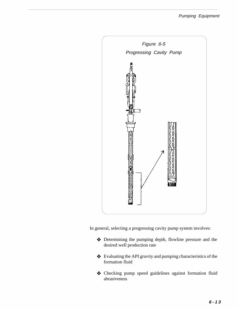
Figure 6-5
Progressing Cavity Pump
:
he
he
id
Pumping Equipment
In general, selecting a progressing cavity pump system involves
❖ Determining the pumping depth, flowline pressure and tdesired well production rate
❖ Evaluating the API gravity and pumping characteristics of tformation fluid
❖ Checking pump speed guidelines against formation fluabrasiveness
6 - 1 3
6 Selecting Production Equipment and FacilitiesChapter
6 - 1 4
ity
fer
d
These general guidelines will help you to install a progressing cavpump in the wellbore:
1. Attach the pump’s stator to the first joint of productiontubing and insert the tubing string into the well.
2. Run and set the production tubing.
3. Attach the pump’s rotor to the first sucker rod and insert thesucker rod string into the production tubing.
4. Install rod guides at regular intervals in the sucker rod stringto prevent excessive rod and tubing wear.
Installing a Progressing Cavity Pump
Operating experience in the Black Warrior Basin has shown thatyou should size the pump to run continuously instead of intermit-tently. Intermittent operation may allow sand or coal fines tosettle and plug the pump when you shut in the well. Continuousoperation keeps the sand moving up the wellbore.
For more information on progressing cavity pumping systems, reto Additional Resources at the end of this chapter.
❖ Evaluating pump compatibility with any chemical additivesto be used
❖ Determining the appropriate pump size and operating spee
❖ Determining the proper sucker rod size
❖ Selecting the proper surface drive head
❖ Selecting the appropriate prime mover and drive system
❈❈❈❈❈ Important
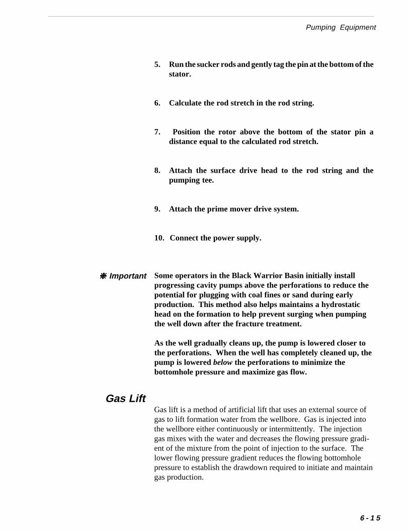
Pumping Equipment
Gas Lift
5. Run the sucker rods and gently tag the pin at the bottom of thestator.
6. Calculate the rod stretch in the rod string.
7. Position the rotor above the bottom of the stator pin adistance equal to the calculated rod stretch.
8. Attach the surface drive head to the rod string and thepumping tee.
9. Attach the prime mover drive system.
10. Connect the power supply.
Gas lift is a method of artificial lift that uses an external source ofgas to lift formation water from the wellbore. Gas is injected intothe wellbore either continuously or intermittently. The injectiongas mixes with the water and decreases the flowing pressure gradi-ent of the mixture from the point of injection to the surface. Thelower flowing pressure gradient reduces the flowing bottomholepressure to establish the drawdown required to initiate and maintaingas production.
Some operators in the Black Warrior Basin initially installprogressing cavity pumps above the perforations to reduce thepotential for plugging with coal fines or sand during earlyproduction. This method also helps maintains a hydrostatichead on the formation to help prevent surging when pumpingthe well down after the fracture treatment.
As the well gradually cleans up, the pump is lowered closer tothe perforations. When the well has completely cleaned up, thepump is lowered below the perforations to minimize thebottomhole pressure and maximize gas flow.
❈❈❈❈❈ Important
6 - 1 5
6 Selecting Production Equipment and FacilitiesChapter
d ingasaneringmorep the andted.
d the the
6 - 1 6
The gas lift system consists of a series of gas lift valves housemandrels which are spaced at intervals in the tubing string. Two lift injection methods have been used to produce coalbed methwells. The least common method is to inject gas down the tubing stand produce water and gas up the annulus. The method used often is to inject gas down the casing and produce water and gas utubing string. In either case, aerating the water reduces its densityallows it to flow to the surface where the gas and water are separaThe produced water is then sent to the water disposal system anmethane gas is either recycled to continue gas lifting or sent togathering system. Figure 6-6 shows a typical gas lift installation.
Figure 6-6
Gas Lift Installation
ps,ss.sal.
of-
fthe
ftg
asedsgithal.
s
ricer,se of
s totleallgthe
E
Pumping Equipment
Though not as popular as beam pumps or progressing cavity pumgas lift has been used in the Black Warrior Basin with some succeGas lift can be a particularly attractive method of artificial lift in areawhere electric power is unavailable or its cost makes it uneconomic
The main advantages of gas lift are the ability to handle productionsolids with little or no mechanical problems and the ability to accommodate a wide range of initial production rates.
A major limitation of a gas lift system is the need for a source ocompressed gas for initial operation. An additional disadvantage is need to train field people to operate the system properly.
If you install a gas lift system, you can run wireline-retrievable gas livalves to optimize performance and eliminate the cost of pullintubing when valve replacement is needed.
In 1985, GRI conducted a study to determine the applicability of glift to coalbed methane production in the Black Warrior Basin. Thstudy concluded that initiating production of coalbed methane fielusing gas lift is more cost effective than using conventional pumpinunits. The study also showed that as water production declines wtime, smaller conventional pumping units may be more economicFor more information on this study, refer to“A Field Evaluation of Gas Lift and Progressive Cavity Pumps aEffective Dewatering Methods for Coalbed Methane Wells.” SeeAdditional Resources at the end of this chapter.
Operators in the Black Warrior Basin have successfully used electsubmersible pumps to produce coalbed methane wells. Howevthese pumps have not gained widespread use in this basin becauproblems with coal fines and scales.
In the Deerlick Creek Field in the Black Warrior Basin, electricsubmersible pumps have been used successfully in bounding wellde-water the field. These wells pumped high rates of water but litgas. When these dewatering wells were temporarily shut-in, overproduction from the field declined significantly. Continued pumpinwith electric submersible pumps has increased dewatering of reservoir and increased gas production from the field.
lectric Submersible Pumps
6 - 1 7
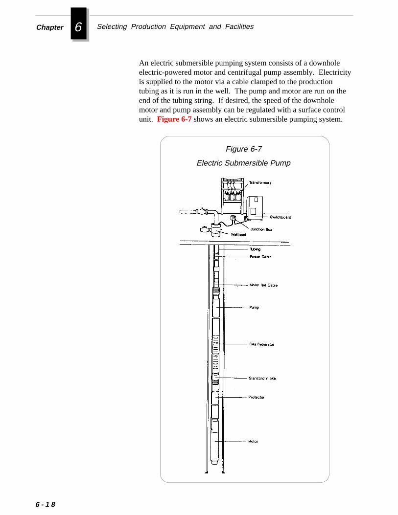
6 Selecting Production Equipment and FacilitiesChapter
eicity
the
trol.
6 - 1 8
An electric submersible pumping system consists of a downholelectric-powered motor and centrifugal pump assembly. Electris supplied to the motor via a cable clamped to the productiontubing as it is run in the well. The pump and motor are run on end of the tubing string. If desired, the speed of the downholemotor and pump assembly can be regulated with a surface conunit. Figure 6-7 shows an electric submersible pumping system
Figure 6-7
Electric Submersible Pump
Power Supply for Pumping Equipment
ity
en-
edo
Because the motor is cooled by fluid passing down the annulusto the intake of the pump, the pump is normally placed abovethe producing zone. Alternatively, a shroud can be installedwith the pump to direct fluid past the motor if the pump isplaced below the producing zone. In any case, the well shouldnever be pumped dry.
❈❈❈❈❈ Important
The main advantages of electric submersible pumps are their abilto lift large volumes of water and their quiet, efficient operation.Two significant limitations of electric submersible pumps are theirhigh cost (both purchase cost and installation/maintenance costs)and their susceptibility to burnout if they run dry.
Because electric submersible pumps can effectively lift largevolumes of water, they may be especially attractive in wells withhigh water production. For example, the water level may be highin a wellbore because of additional water influx from a non-coalzone. Similarly, a coal zone with a large permeability may producwater rates that preclude dewatering an extended area with convetional pumping units.
The heat generated by electric submersible pumps can causesevere deposition of scale on the downhole pump. This scalecan eventually plug the pump and cause it to burn up. Becausescale deposition presents serious problems in some parts of theBlack Warrior Basin, electric submersible pumps may not bepractical in these areas.
If an electric submersible pump becomes stuck in a well be-cause of sand or coal fines, it is usually difficult to retrievebecause the O.D. of the housing on the pump is larger than theO.D. of the production tubing above it.
❈❈❈❈❈ Important
Power Supply for Pumping EquipmentRegardless of the type of pumps you select to produce your coalbwells, you will need to decide how to power the pumps. You have twbasic choices of power supply:
• Natural Gas Power
• Electric Power
6 - 1 9
6 Selecting Production Equipment and FacilitiesChapter
.
.
6 - 2 0
You should base your decision of power supply on both the eco-nomic and the operational benefits and limitations of each method
Natural gas may provide the most efficient and cost-effectivepower source if your field is in a remote area without nearbyelectric power.
Natural gas power can provide these benefits:
❖ May have lower initial cost
❖ Can use low-cost natural gas produced on location
❖ Eliminates lengthy and costly negotiations with powercompanies
When compared to electric-powered pumps, natural gas-poweredpumps also have several disadvantages:
❖ Require higher maintenance
❖ Require a backup gas supply
❖ More susceptible to vandalism and theft
❖ Cold weather may interrupt gas supply
Natural Gas Power
Electric power may provide the most efficient and cost-effectivepower source if your field has ready access to existing power lines
In the Black Warrior Basin, most operators use electric powerbecause it requires relatively little maintenance and its cost can beamortized over several years with the power company.In most cases, electric power can provide these benefits:
❖ Requires low initial capital cost
❖ Provides a more reliable power supply
Electric Power
our
in
ry
nly
Power Supply for Pumping Equipment
❖ Requires lower maintenance
❖ Produces no air pollution
❖ Provides quieter operation
❖ Contains few parts that can be stolen
When compared to natural gas power, electric power also hasseveral disadvantages:
❖ May require a higher initial cost if you install your owndistribution system
❖ May require access rights-of-way for power lines
In general, you can supply electric power to your field by either:
• Installing Your Own Power Lines
• Utility Company Installation
Installing Your Own Power LinesIf electric power is available nearby, you may choose to install yown power distribution network in the field and then connect it tothe local utility system. The operator of the Rock Creek project the Black Warrior Basin elected to install such a field network.The operator estimates the total cost to clear right-of-ways andinstall the network at approximately $35,000 per mile of powerline.
If the field contains several wells grouped fairly closely together,you may consider taking delivery of the electricity from the powecompany at a single point and then installing your own secondarlines to the individual wells. This may be the most economicalmethod because you have only one meter and therefore incur oone demand charge from the power company.
The primary factors you should consider in installing your ownlines are:
Methods for Installing Electric Power
6 - 2 1
6 Selecting Production Equipment and FacilitiesChapter
6 - 2 2
❖ Initial cost for equipment and installation
❖ Cost to obtain and clear rights-of-way
❖ Ongoing cost to maintain the network
❖ Requirements for inspection by local government agenciesand the utility company
❖ Taking delivery of electricity at a single point (i.e., onemeter) to lower the demand charge
Utility Company InstallationThe alternative to installing your own field power network is to tohave a local utility company supply service to the field. The utilitycompany could either provide individual power lines to each wellsite based on a well’s estimated power needs or it could provideservice connect/disconnect boxes on poles placed at selected pointsthroughout the field.
The primary factors you should consider when having a utilitycompany install a power network are:
❖ Total cost for equipment and installation, and how paymentwill be structured
❖ Rates for usage of electricity, including any minimumcharge
❖ Responsibility for maintenance of lines
❖ Scheduling of installation to meet production needs
❖ Inspection requirements of the utility company beforebeginning or expanding service
❖ Union requirements of the utility company for connectingor disconnecting equipment (e.g., Are electrical specialistsrequired?)
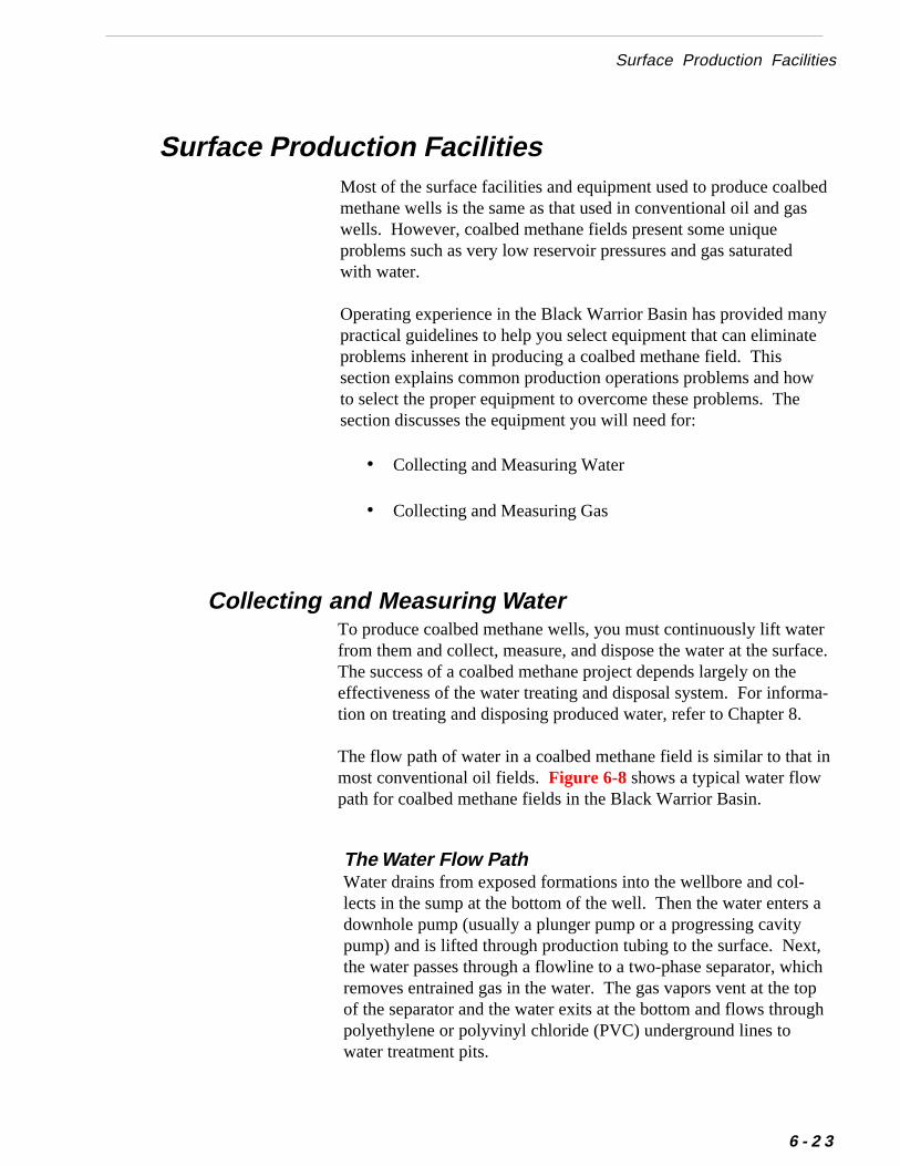
Surface Production Facilities
eds
nyte
w
erace.
a-
Surface Production FacilitiesMost of the surface facilities and equipment used to produce coalbmethane wells is the same as that used in conventional oil and gawells. However, coalbed methane fields present some uniqueproblems such as very low reservoir pressures and gas saturatedwith water.
Operating experience in the Black Warrior Basin has provided mapractical guidelines to help you select equipment that can eliminaproblems inherent in producing a coalbed methane field. Thissection explains common production operations problems and hoto select the proper equipment to overcome these problems. Thesection discusses the equipment you will need for:
• Collecting and Measuring Water
• Collecting and Measuring Gas
To produce coalbed methane wells, you must continuously lift watfrom them and collect, measure, and dispose the water at the surfThe success of a coalbed methane project depends largely on theeffectiveness of the water treating and disposal system. For informtion on treating and disposing produced water, refer to Chapter 8.
Collecting and Measuring Water
in
a
t,ichtopgh
The flow path of water in a coalbed methane field is similar to thatmost conventional oil fields. Figure 6-8 shows a typical water flowpath for coalbed methane fields in the Black Warrior Basin.
The Water Flow PathWater drains from exposed formations into the wellbore and col-lects in the sump at the bottom of the well. Then the water entersdownhole pump (usually a plunger pump or a progressing cavitypump) and is lifted through production tubing to the surface. Nexthe water passes through a flowline to a two-phase separator, whremoves entrained gas in the water. The gas vapors vent at the of the separator and the water exits at the bottom and flows throupolyethylene or polyvinyl chloride (PVC) underground lines towater treatment pits.
6 - 2 3
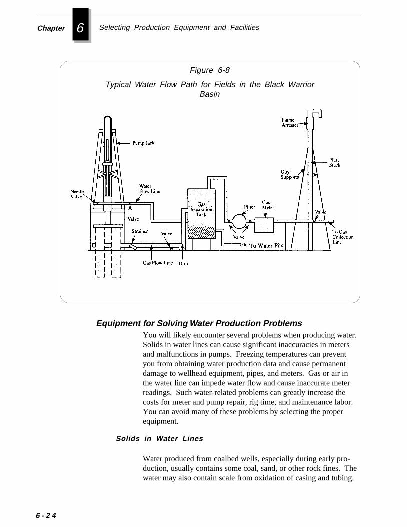
6 Selecting Production Equipment and FacilitiesChapter
Figure 6-8
Typical Water Flow Path for Fields in the Black WarriorBasin
6 - 2 4
r.st
nr
r.
heg.
You will likely encounter several problems when producing wateSolids in water lines can cause significant inaccuracies in meterand malfunctions in pumps. Freezing temperatures can prevenyou from obtaining water production data and cause permanentdamage to wellhead equipment, pipes, and meters. Gas or air ithe water line can impede water flow and cause inaccurate metereadings. Such water-related problems can greatly increase thecosts for meter and pump repair, rig time, and maintenance laboYou can avoid many of these problems by selecting the properequipment.
Water produced from coalbed wells, especially during early pro-duction, usually contains some coal, sand, or other rock fines. Twater may also contain scale from oxidation of casing and tubin
Equipment for Solving Water Production Problems
Solids in Water Lines
Surface Production Facilities
r
r
r,
In addition, if formation water contains a large amount of salts,precipitates may form in surface flow lines and further increase thetotal solids in the water.
Except for very large particles, most solids pass through the waterproduction and metering system without difficulty. The solidsremaining in the system usually accumulate in the housing chambeof the water meter, which can eventually impair and finally stop themeasuring mechanism. Some meters may, however, repeatedlymalfunction within several days after installation. Rock materialcan lodge in valve openings in the downhole pumping mechanism.Usually this material is coal or shale that has sloughed off forma-tions exposed in the wellbore. This material is most likely to plugand stop the downhole pump during the first few days of produc-tion, especially after the well has been stimulated.
Solution To prevent large solids from plugging and damagingthe surface equipment and meters, install a wire-wrapped screen(the type used in water wells) on the bottom of the pump.
Most large pieces of solid debris carried through the tubing settle inthe separator. You can remove the remaining solids suspended inthe flow system by installing a strainer downstream of the separatoand upstream of the water meter.
Produced water sometimes freezes inside surface lines, restrictingflow and causing leaks. Extended freezing weather conditions canpermanently damage wellhead equipment, pipes, and meters.
Gas-producing coals are normally several hundred feet deep, andthe water produced is usually warmer than winter surface tempera-tures. However, if you control pumping with a timer, there aretimes when no water is moving through surface lines. Waterremaining in the lines during these periods cools rapidly and mayfreeze.
Solution To prevent freezing, wrap surface lines with electricheat tape and then cover them with waterproof insulation. In areaswhere severe and prolonged freezing temperatures are common,bury water lines below the frostline. In addition, place meters,water filters, and separators inside small, insulated houses. Furtheyou can install heat lamps inside the buildings as a simple, effec
Freezing of Water Lines
6 - 2 5
6 Selecting Production Equipment and FacilitiesChapter
neorsd
sw
ern
6 - 2 6
tly.e,
- in
tive, and inexpensive prevention against freezing. Ventilate allhouses, especially those using heat lamps.
Use only fixtures and wiring approved and appropriate forsuch equipment enclosures.
Gas passing through positive-displacement water meters or turbimeters is measured as water and may account for significant errin production records. Gas enters water flow lines either dissolvein the water or as free gas drawn directly into the tubing by thedownhole pump.
Improper pump cycle settings or continuous pump operationswhich lower water level in the wellbore to the bottom of the pumpcause gas to be drawn directly into the tubing and pumped to thesurface. This gas in the water can cause large errors in meteredwater measurements. Tests conducted at wells where fluid levelwere known to be at or near the base of the downhole pump shometer readings from 20 to 75 percent greater than the actual vol-ume of water produced.
Solution You can remove gas from the water line and improvewater meter accuracy by installing a separator in the surface watflow system. Alternatively, you can install a simple 30 to 50 gallovented separation tank.
Air can enter water collection lines at high points in the line. Thisproblem may be more severe when wells are pumped intermittenbecause of long periods of no water movement through the linesWhen pockets of air or entrained gas are trapped in the water linthey compress much like a spring, preventing the water frommoving through the line.
Solution Install a vacuum breaker device at high points in thewater line. A vacuum breaker prevents a vacuum lock from stopping water flow in the line and releases air trapped at high pointsthe line.
Gas in Water Lines
Air Trapped in Water Collection Lines
▲ ▲ ▲ ▲ ▲ Caution
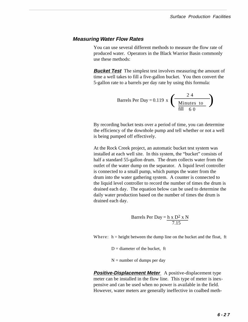
of
f
ell
fer
is the
ft
-
-
Surface Production Facilities
You can use several different methods to measure the flow rate produced water. Operators in the Black Warrior Basin commonlyuse these methods:
Bucket Test The simplest test involves measuring the amount otime a well takes to fill a five-gallon bucket. You then convert the5-gallon rate to a barrels per day rate by using this formula:
Barrels Per Day = 0.119 x
Measuring Water Flow Rates
)2 4( Minutes tofill 6 0
By recording bucket tests over a period of time, you can determinthe efficiency of the downhole pump and tell whether or not a weis being pumped off effectively.
At the Rock Creek project, an automatic bucket test system wasinstalled at each well site. In this system, the “bucket” consists ohalf a standard 55-gallon drum. The drum collects water from thoutlet of the water dump on the separator. A liquid level controlleis connected to a small pump, which pumps the water from thedrum into the water gathering system. A counter is connected tothe liquid level controller to record the number of times the drum drained each day. The equation below can be used to determinedaily water production based on the number of times the drum isdrained each day.
Barrels Per Day = h x D2 x N7.15
h = height between the dump line on the bucket and the float,
D = diameter of the bucket, ft
N = number of dumps per day
Where:
Positive-Displacement Meter A positive-displacement typemeter can be installed in the flow line. This type of meter is inexpensive and can be used when no power is available in the field.However, water meters are generally ineffective in coalbed meth
6 - 2 7
6 Selecting Production Equipment and FacilitiesChapter
d
he
S
6 - 2 8
ane fields because small amounts of coal fines, sand grains, orfracturing gel can easily plug the meter.
Turbine Meter This meter is essentially a water meter withturbine blades that is installed in line. Turbine meters can be sizefor the rate and volume of flow expected. Like the positive-displacement meter, the accuracy of the turbine meter is severelyimpaired by debris and flow rates outside the operating range of tmeter.
electing Other Equipment for Water ProductionThese guidelines will help you to properly select other equipmentfor producing water in a coalbed methane field:
■ When practical, install separators at each well site insteadof piping all produced water directly to a central separationfacility.Water carries fines and sludge that can cause plugging. Themore water you can remove at the well site, the less pluggingproblems you will have downstream.
■ Select water pipelines with a large enough diameter tocarry the estimated volume of produced water and tominimize frictional pressure losses, which increasebackpressure at the wellhead.
▲▲▲▲▲ CautionFlow lines that are too large in diameter can cause solids todrop out of the water and create plugging problems. Apipe partially full of water will tend to plug more easilythan a pipe full of moving water. To prevent solids fromsettling in the flow lines, the flow velocity should be aminimum of 3 ft/second.
■ If the frictional pressure losses from flow lines createsexcessive backpressure on the surface water facilities, youcan install booster pumps at the well sites to move the waterthrough the lines and reduce wellhead pressure.
h
nd
/
l
e
sing-
dany
Surface Production Facilities
Collecting and measuring gas in a coalbed methane field is mucthe same as in a low-pressure oil field. You will find many simi-larities in the flow path of the fluids, the production equipment, athe operational problems.
Coalbed methane wells usually produce gas through the casingproduction tubing annulus. The wells normally produce underminimum back-pressure to optimize gas desorption from the coaand drainage of the water. Once gas reaches the surface, it isnormally piped to a two-phase separator, which removes removwater from the gas. (Alternatively, the gas can be piped directlyinto the gas gathering system to reduce backpressure on the cahead.) Then the gas flows through an orifice meter with a3-pen chart recorder where it is measured. Next, the gas is pipethrough a field collection line to a gas scrubber, which removes
Collecting and Measuring Gas
The Gas Flow Path
the gas
aterasracyallds of
gasy
o gasents, ofrature
bilityon-
remaining water before the gas enters the compressor. Finally,gas exits the compressor, flows through a dehydrator and salesmeter, and finally, into the sales gas pipeline. Figure 6-9 shows atypical gas flow path for fields in the Black Warrior Basin.
You will likely experience several problems when producingcoalbed methane gas. Gas produced from coalbeds contains wvapor that condenses and collects along various points in the gline, including the meter. Water build-up decreases meter accuand can damage working components. The effects of even smamounts of water in gas lines are most pronounced during periofreezing weather. In addition, rock fines accumulate within the meter over time, causing measurement inaccuracy and possibldamage to the meter.
The moisture content of coalbed gas has to be sufficiently low tassure accurate measurement of gas flow. In addition, coalbedsold commercially must meet requirements of purchase agreemwhich usually limit the water content to approximately 7 poundswater per million cubic feet of gas measured at standard tempeand pressure.
As warm coalbed gas cools at the surface, it loses some of its ato carry water and the water therefore condenses. The water c
Equipment For Solving Gas Production Problems
Water in Gas Lines
6 - 2 9
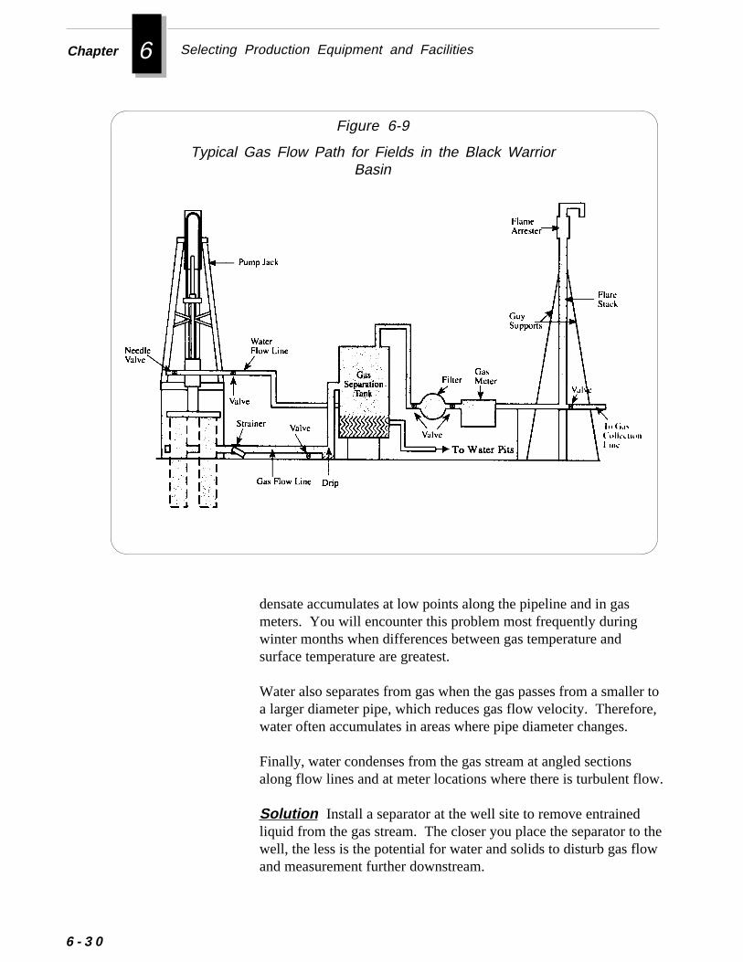
6 Selecting Production Equipment and FacilitiesChapter
Figure 6-9
Typical Gas Flow Path for Fields in the Black WarriorBasin
ller tore,
ow.
thew
6 - 3 0
densate accumulates at low points along the pipeline and in gasmeters. You will encounter this problem most frequently duringwinter months when differences between gas temperature andsurface temperature are greatest.
Water also separates from gas when the gas passes from a smaa larger diameter pipe, which reduces gas flow velocity. Therefowater often accumulates in areas where pipe diameter changes.
Finally, water condenses from the gas stream at angled sectionsalong flow lines and at meter locations where there is turbulent fl
Solution Install a separator at the well site to remove entrainedliquid from the gas stream. The closer you place the separator towell, the less is the potential for water and solids to disturb gas floand measurement further downstream.
r
l
Surface Production Facilities
Also, install drips at low points in the gas lines to remove liquidfrom the gas stream or liquid that has accumulated in the pipeline.A drip is simply a 10-15 foot length of pipe tied into the line. Thedrip collects water in the line and allows drainage of the waterthrough a valve in the pipe.
Drips are available in two styles: manual or automatic. You mustperiodically open a valve and drain a manual drip. Automatic dripsoperate with a float system that automatically dumps the collectedwater when it reaches a pre-set level.
Problems with water in gas lines increase during periods of lowtemperature because conditions for condensation are intensified.The problem becomes severe when temperatures drop belowfreezing. Even small amounts of ice in gas flow lines increasebackpressure and reduce gas production. Ice can also form in gasmeters and severely damage the instruments.
Solution To prevent ice formation in gas lines near the wellhead,wrap the lines with electric heat tape and then cover them withwaterproof fiberglass insulation. In addition, equip well sites withsmall insulated meters houses that contain heat lamps. Be sure toadequately ventilate the meter houses. Finally, increase the numbeof routine field inspections during especially cold weather to assureminimum condensate build up.
Under normal flowing conditions, particles of rock or other solidmaterial accumulate in most gas meters over time. If you do notcorrect this problem, solids will eventually cause any type of meterto malfunction. Rotary meters are the most susceptible to malfunc-tion because of close tolerance between components of the rotatingcartridge. Diaphragm meters usually continue to operate with smalamounts of solids build-up, but meter accuracy diminishes asportions of the meter’s measuring reservoir fill with solids. Tur-bine meters normally allow very small material (less than onemillimeter in diameter) to pass through its inner mechanisms.
Solution To prevent solids from plugging meters, install a car-tridge-type filter with a fiberglass filtering element or a line-strainer (a steel cartridge containing numerous 3/64-inch holes).
Solids in Gas Lines
Freezing of Gas Lines and Meters
6 - 3 1
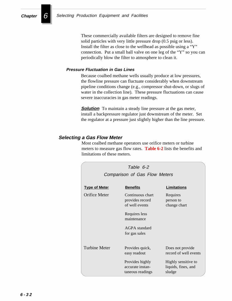
6 Selecting Production Equipment and FacilitiesChapter
e
can
es,ams ofuse
Setsure.
6 - 3 2
These commercially available filters are designed to remove finsolid particles with very little pressure drop (0.5 psig or less).Install the filter as close to the wellhead as possible using a “Y”connection. Put a small ball valve on one leg of the “Y” so you periodically blow the filter to atmosphere to clean it.
Because coalbed methane wells usually produce at low pressurthe flowline pressure can fluctuate considerably when downstrepipeline conditions change (e.g., compressor shut-down, or slugwater in the collection line). These pressure fluctuations can casevere inaccuracies in gas meter readings.
Solution To maintain a steady line pressure at the gas meter,install a backpressure regulator just downstream of the meter. the regulator at a pressure just slightly higher than the line pres
Table 6-2
Comparison of Gas Flow Meters
Most coalbed methane operators use orifice meters or turbinemeters to measure gas flow rates. Table 6-2 lists the benefits andlimitations of these meters.
Orifice Meter Continuous chart Requiresprovides record person toof well events change chart
Type of Mete r Benefits Limitations
Requires lessmaintenance
AGPA standardfor gas sales
Provides highly Highly sensitive toaccurate instan- liquids, fines, andtaneous readings sludge
Turbine Meter Provides quick, Does not provideeasy readout record of well events
Pressure Fluctuation in Gas Lines
Selecting a Gas Flow Meter
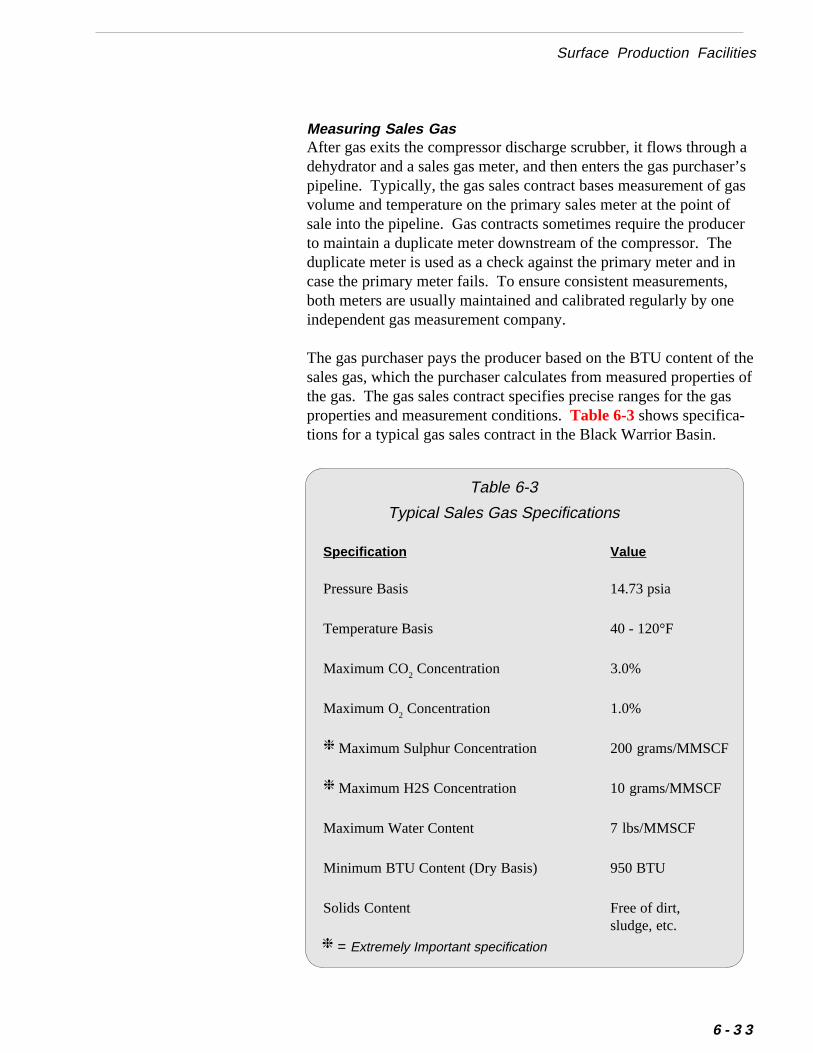
aser’sgasfcer
in,
f thees ofas
Surface Production Facilities
Measuring Sales GasAfter gas exits the compressor discharge scrubber, it flows throughdehydrator and a sales gas meter, and then enters the gas purchapipeline. Typically, the gas sales contract bases measurement of volume and temperature on the primary sales meter at the point osale into the pipeline. Gas contracts sometimes require the produto maintain a duplicate meter downstream of the compressor. Theduplicate meter is used as a check against the primary meter and case the primary meter fails. To ensure consistent measurementsboth meters are usually maintained and calibrated regularly by oneindependent gas measurement company.
The gas purchaser pays the producer based on the BTU content osales gas, which the purchaser calculates from measured propertithe gas. The gas sales contract specifies precise ranges for the gproperties and measurement conditions. Table 6-3 shows specifica-tions for a typical gas sales contract in the Black Warrior Basin.
Specification Value
Pressure Basis 14.73 psia
Temperature Basis 40 - 120°F
Maximum CO2 Concentration 3.0%
Maximum O2 Concentration 1.0%
❈ Maximum Sulphur Concentration 200 grams/MMSCF
❈ Maximum H2S Concentration 10 grams/MMSCF
Maximum Water Content 7 lbs/MMSCF
Minimum BTU Content (Dry Basis) 950 BTU
Solids Content Free of dirt,sludge, etc.
Table 6-3
Typical Sales Gas Specifications
❈ = Extremely Important specification
6 - 3 3
6 Selecting Production Equipment and FacilitiesChapter
to
6 - 3 4
Selecting Other Equipment for Gas Production
The guidelines below will help you to properly select other impor-tant equipment for producing gas from a coalbed methane field:
■■■■■ If the compressor discharge scrubber cannot dry the gas tothe required sales gas specifications, you can install a glycoldehydrator to further dry the gas.A glycol dehydrator circulates gas up through liquid glycol,which has an affinity for water. The water in the gas adheres the glycol, which is then heated to evaporate the water. Thede-watered glycol then recirculates back through a tower toremove more water.
■ Install a manual globe-type valve on the wellhead to regu-late gas flow rate and to control well surging.
Do not install a plate-type valve on the wellhead. Productionof any solids can quickly erode the seat on a plate valve.
Never vent gas without the approval of the oil and gasagencies and environmental agencies in your area.
■ When practical, avoid installing gas flow lines across lowareas. Attempt to place lines on level or only slightly slopingground to prevent water from accumulating in the lines.
■ Install a gas flare stack on the well site to vent gas during apilot test program or during an emergency in a producingfield.
■ Install a gas scrubber (small separator) upstream of theinlet to the gas compressor to prevent water from enteringand damaging the compressor.
■■■■■ If the gas scrubber will not drain quickly enough by grav-ity, you can install a small pneumatic pump and water level
▲ ▲ ▲ ▲ ▲ Caution
❈ ❈ ❈ ❈ ❈ Important
-nox.
raln be
on.asicue
nlytant
stype
tean-
w
Gas Compressors
controller on the scrubber to prevent water from filling itand then entering the compressor.This type of pump is especially effective in handling slugs ofwater, which are common in coalbed methane production.
■ When installing the separator, install a bypass line aroundthe separator.This bypass will allow you to re-route gas when you need towork on the separator. More importantly, it will enable you tobypass the separator later in a well’s life when the water contains little entrained gas. By bypassing the separator, you calower wellhead pressure and reduce leaking on the stuffing b
Because methane gas produced from coal seams has little natupressure, you must compress it to a higher pressure before it cadelivered to a pipeline for transportation and sale. Compressionequipment used for conventional natural gas production can beeasily adapted to the requirements of coalbed methane productiSelecting an efficient, reliable compressor package requires a bunderstanding of the various types of compressors and the uniqcharacteristics of coalbed methane production.
This section explains the design, benefits, and limitations of thetypes of compressors and drivers (compressor engines) commoused to compress coalbed methane gas. It also presents imporguidelines for selecting auxiliary compressor equipment.
The two basic types of compressors commonly used for coalbedmethane production are rotary compressors and reciprocatingcompressors. Both types are positive displacement compressorthat increase the pressure of gas by reducing its volume. Each has its own advantages and disadvantages .
The rotary design uses either vanes, lobes, or screws which rotawithin a casing to compress and displace gas. The principal advtage of this design is its ability to compress large quantities of lopressure gas. The rotary compressor is particularly suitable for
Types of Compressors
Rotary Compressors
Gas Compressors
6 - 3 5
6 Selecting Production Equipment and FacilitiesChapter
--
e line ar
and.tsally
-
ring tores-
me,e-pac-
oue,-ipro-
6 - 3 6
coalbed methane production as the first stage compressor in agathering system. These units are compact, have a lower initialcost than a reciprocating unit, and are simple to maintain.
The rotary compressor is at a disadvantage, however, when youneed a higher discharge pressure or when you encounter largepressure differentials or pressure fluctuations in the gas line. Because of its valve-less design, the rotary compressor always compresses gas to its designed discharge pressure, regardless of thpressure. Therefore, the rotary compressor is less efficient thanreciprocating unit when you operate at pressure conditions othethan those for which it was designed.
The reciprocating compressor consists of a piston moving back forth within a cylinder. Each stroke displaces a positive volumeSpring-loaded valves open whenever a pressure differential exisacross the valve. When the valve opens, suction gas automaticenters the cylinder and discharge gas exits.
The reciprocating compressor is the most widely used of all compression equipment. Although it is more complex than a rotaryunit, the reciprocating compressor operates more efficiently andcan accommodate higher discharge pressures, greater pressuredifferentials, and fluctuations in pressure and capacity.
You can use a multi-stage reciprocating compressor on coalbedmethane projects to meet the entire compression need -- gathethe wellhead gas at low pressure and increasing its pressure upthe pipeline pressure. You can also use it as a first-stage compsor in a gathering system and as a booster to the sales line.
Each compressor is designed to handle a specific range of volupressure and pressure differential. The cylinder’s piston displacment and and clearance volume determine the compressor’s caity. By adding clearance volume to the cylinder, you will reducethe compressor’s volumetric efficiency and its capacity. When yneed to change the compressor’s capacity or operating pressuryou can adjust the cylinder clearance by setting the variable volume pocket. Because of this adjustment, you can operate a reccating compressor more efficiently than a rotary compressor atother than design conditions.
Reciprocating Compressors
,s
to
s,
eds
er.lin.utith
t
to
ussing
y of
r
Gas Compressors
Types of DriversIn addition to selecting a compressor, you must also select thedriver, or engine, to power the compressor. For field applicationsyou have two alternatives for drivers: electric motors or natural gaengines. Although electric motors are simple, reliable, and easy operate and maintain, the cost of electric power usually dictatesusing natural gas engines for the savings in fuel cost. Natural gaengines also allow you to adjust capacity by varying engine speedbut regular A.C. motors do not.
You can choose from two basic types of engines: high-speedengines and integral engines. High speed engines operate at spefrom 900 to 1800 rpm. You can connect them directly to thecompressor with a coupling or by using V-belts (depending oncompressor operating speed).
Integral engines operate at speeds of 400 rpm and less. The powand compressor cylinders share a common frame and crankshaftAlthough they cost more initially than high-speed engines, integraengines are more efficient, more reliable, and cost less to maintaSome integral engines can be built as a skid-mounted package, bthe high-speed design provides more horsepower in less space wless weight than does an integral engine.
Selecting Gas Compressors
When selecting a gas compressor, consult a compressor specialiswho has experience with low pressure coalbed methane fields.Sizing a compressor for a particular application requires precisecalculation of several factors. Compression equipment supplierscan perform computer analyses to determine the best equipment use for your application.
When you meet with a compressor specialist, be prepared to discthe volumes of gas you expect to produce and compress. Prepara forecast of gas production for the life of the field will help thespecialist assess compression requirements and suggest a varietoptions.
In addition to the two primary components -compressor and drive- you may need other accessories to complete the compressorpackage. These items may include:
Selecting Auxiliary Compressor Equipment
6 - 3 7
6 Selecting Production Equipment and FacilitiesChapter
6 - 3 8
e
• Gas scrubbers and pumps
• High level shut-down controls
• Fuel filters
• Solids filters
• Pilot devices
• Catalytic converters
The design of the auxiliary equipment should accommodate yourparticular operating environment and the characteristics of methanproduced from coalbeds. The guidelines below have proveneffective in the Black Warrior Basin:
■■■■■ To prevent water from entering and damaging the com-pressor, you should install a gas scrubber (small waterseparation unit) on the compressor skid.Because coalbed methane is saturated with water vapor, aproduction separator may not remove all the water.
■■■■■ If the gas scrubber will not drain quickly enough by grav-ity, install a small pneumatic pump and water level control-ler on the scrubber to prevent water from filling it andthen entering the compressor.This type of pump is especially effective in handling slugs ofwater, which are common in coalbed methane production.
■■■■■ To protect the compressor from damaging slugs of waterthat might get through the scrubber, install an accuratehigh level shut-down control on the compressor controlpanel.
■■■■■ If you operate the compressor with a vacuum at the inlet,install a pneumatic pump on the scrubber.If the scrubber has a vacuum on the inside, opening a dumpvalve will not dump the water, but it could suck air into thesystem, causing further problems.
Gas Compressors
eam.
.e thes
-e
on
e the
res-t
-
nd.
■■■■■ Make sure fuel gas is taken downstream of the compressordischarge, after the gas has been dehydrated.Water can cause significant problems if it enters the engine’sfuel gas system.
■■■■■ Install a fuel filtering unit to further protect the fuel fromwater.
■■■■■ To prevent solids from entering the compressor, install afilter screen in front of the gas scrubber.Sometimes particles of coal or sand are carried in the gas strIf these contaminants enter the compressor, they will wear itsinternal parts.
■■■■■ To prevent excessive loading of the compressor, install apilot device that can control the suction pressure.A pilot device is a flow regulator that is controlled by pressureAs the pressure in the line to the compressor increases abovsuction pressure limit, the regulator restricts gas flow and thuthe inlet pressure as well.
The loading or required hydraulic horsepower of a given compressor is a function of the volume of gas compressed and thsuction and discharge pressures. Because coalbed methanefields produce at such low pressures, a small change in suctipressure can greatly affect the operating performance of thecompressor. An increase in the suction pressure can increashydraulic horsepower requirements, which can overload thecompressor and result in engine failure. Though every compsor is equipped with emergency shut-down devices to prevenhigh suction pressures, installing a pilot device to regulatesuction pressures to the compressor may help eliminate compressor shut-downs due to high suction pressures.
■■■■■ If temporary changes in field operating conditions requireadditional compression, you may consider leasing or pur-chasing satellite compressors instead of making costly modi-fications to the main compressor.You can easily move a small, skid-mounted compressor arouthe field to effectively meet temporary compression demands
6 - 3 9
6 Selecting Production Equipment and FacilitiesChapter
ir
t
s,
f
s
6 - 4 0
■■■■■ Check with the state and federal environmental agencies forrequirements on gas compressors.Environmental agencies may require that you include catalyticconverters on compressors to meet emissions standards for aquality. You may be able to avoid installing catalytic convertersby spacing compressors so that their combined emissions do noexceed the regulation limit for a given area. Depending on the sizeof the compressor, you may also have to obtain a permit from thestate environmental regulatory agency before the compressor isinstalled.
Selecting the proper gas compression equipment for your field iscritical to successful coalbed methane production. Once the equip-ment is installed, you must practice effective maintenance to helpensure consistent compressor operation. For information on main-taining gas compressors and equipment, refer to Chapter 7.
Gas Dehydration EquipmentBecause coalbed methane gas is produced at relatively low pressurethe gas can contain large amounts of water. This water must beremoved to prevent formation of hydrates in the transmission lines andto meet gas contract specifications. The most common method oremoving water from gas is by adsorption using liquid dessicants suchas glycols. You can use triethylene glycol (TEG), diethylene glycol(DEG), monoethylene glycol (MEG), or ethylene glycol (EG). TEGis used most often because it can withstand higher temperaturewithout degradation than DEG, MEG, or EG.
A glycol dehydrator system is composed of the equipment below:
❖ Inlet gas scrubber
❖ Glycol-gas contact tower
❖ Glycol heat exchanger
❖ Glycol regenerator
❖ Filter
❖ Glycol pump
Gas Dehydration Equipment
edas
eree
erl
thect.
d
icledss.
eryer ar.-
are,at is
In coalbed methane applications, gas dehydrators are usually installdownstream of the compressor and upstream of the tie-in to the gpurchaser's metering point and transmission line.
The gas from the compressor usually flows into an inlet gas scrubbthat is installed with the glycol dehydrator system. The purpose of thinlet gas scrubber is to prevent slugs of free water from entering thglycol-gas contact tower.
After flowing through the inlet gas scrubber, the gas stream enters thbottom of the glycol-gas contact tower. The inside of the contact towecontains trays or packing which facilitate contact between the glycoand the gas. When the gas contacts the glycol, the glycol absorbs water in the gas. The dry gas then exits through the top of the contatower and the water-rich glycol exits through the bottom of the tower
Before the glycol can be re-circulated, the water must be removefrom it. Therefore, the water-rich glycol flows from the contact towerinto the regenerator, where the glycol is heated (at atmospherpressure) to evaporate the water. The de-watered glycol is then cooby flowing it through the heat exchanger. The cooled glycol then flowback into the top of the contact tower to repeat the dehydration proces
Glycol circulation rates vary from about 2 to 5 gallons of glycol perpound of water to be removed. You can determine the amount of watthat must be removed by subtracting the contract water limit (usuallabout 7 lbs/MMSCF) from the amount of water present in the gas. Thamount of water in the gas can be measured in the field using eithehand-held moisture analyzer or an electronic moisture analyzeAlternatively, you can estimate water content from dew point correlations for natural gas.
The maximum amount of water that may be present in the gas isfunction of the temperature and pressure. At a constant temperatuthe water content of gas is higher at lower pressures and is lower higher pressures. Consequently, dehydrating gas at low pressuresboth difficult and expensive. To alleviate this problem, you shouldinstall dehydrators downstream of the compressor.
Glycol dehydrators are relatively easy to operate and maintain. Toensure efficient operation of the dehydrator, you should periodi-cally check the water content of the outlet gas to verify that it is ator below the maximum allowable value.
6 - 4 1
6 Selecting Production Equipment and FacilitiesChapter
6 - 4 2
thee.
thattracen thes is
ouwer
If gas flow through the dehydrator increases as production fromfield increases, you may need to adjust the glycol circulation rat
You should also check the volume of glycol in the system to ensureexcessive amounts of glycol are not being lost. Glycol absorbs a amount of gas at relatively low pressures. This gas is burned off iregenerator. A small amount of glycol may be lost when the gaburned.
In addition, you should periodically check the pH of the glycol. Yshould maintain the pH of the glycol between 6.0 and 7.5. At lopH levels, the glycol may decompose.
For more information on dehydrating gas, refer to “Engineering DataBook,” listed in Additional Resources at the end of this chapter.
❖ ❖ ❖
Additional Resources
o-
ey,
n-
m-
o-).
Additional Resources
“API Recommended Practice for Design Calculations for SuckerRod Pumping Systems (Conventional Units)”, API RP 11L, ThirdEdition, Dallas (February 1977).
“API Specification for Subsurface Pumps and Fittings, " API Spec11AX, Seventh Edition, Dallas (June 1979).
“Engineering Data Book,” Natural Gas Processers Suppliers Assciation (NGPSA), Tulsa, Oklahoma.
Graves, S.L., “ A Field Evaluation of Gas Lift and Progressive CavityPumps as Effective Dewatering Methods for Coalbed MethanWells,” Quarterly Review of Methane from Coal Seams TechnologVol. 3 no. 2 (September 1985).
Klein, S.T., “The Progressing Cavity Pump in Coalbed MethaneExtraction,” 1991 SPE Eastern Regional Meeting, Lexington, Ketucky (October 22-25).
Lambert, S.W., M.A. Trevits, and P.F. Steidl, “Vertical BoreholeDesign and Completion Practices to Remove Methane Gas froMineable Coalbeds,” U.S. Department of Energy, Carbondale Mining Technology Center, Carbondale, Illinois (1980).
“Petroleum Engineering Handbook,” Society of Petroleum Engi-neers, Richardson, Texas (1987).
Sykes, W.W., “Gathering Systems Concepts-Planning, Design, andConstruction,” Proceedings of the 1989 Coalbed Methane Sympsium, The University of Alabama, Tuscaloosa, Alabama (April 17-20
6 - 4 3
7 Operating Wells and ProductionEquipment
s
Operating coalbed methane wells and production equipmentrequires some specialized production techniques. These techniquehave been learned primarily through trial and error and observation inthe field. For example, field experience at the Rock Creek project hasshown that the manner in which you flow back a well after stimulationmay significantly affect its recovery. Similarly, the procedure you useto pump a well down may influence the productivity of the well.Experience has also shown that you can greatly reduce productiondowntime by learning to diagnose and correct common productionproblems.As you gain operating experience in a particular coalbed methanefield, you will undoubtedly develop techniques that work effectivelyin your area. This chapter will help you begin developing effectiveproduction strategies. It will guide you through:
• Preparing Surface Facilities for Production
• Unloading the Well
• Bringing the Well on Line
• Troubleshooting Well and Equipment Problems
7 Operating Wells and Production EquipmentChapter
-
7 - 2
Preparing Surface Facilities for ProductionAfter the well has been fractured and flowed back, and the pumpingunit has been installed, you should check the surface facilities andgathering system to make sure they are ready to receive productionfrom the well. Performing this check before you bring the well on linewill help prevent unsafe operating conditions, environmental inci-dents, and unnecessary downtime to correct facilities problems.
The various equipment you need to check may vary slightly from fieldto field. Regardless of the type of equipment used, this pre-productioncheck should include not only equipment at the wellhead, but also alldownstream lines and facilities such as separators, meter runs, gathering lines, drips, water treatment facilities and compressors.Before bringing wells on line, check the guidelines below:
■■■■■ Make sure you have complied with all applicable federal,state, and local safety and environmental regulations. Youalso may be required to notify certain regulatory agencies inyour area of your intent to begin production from the field.
■■■■■ Notify the gas purchaser of the date you will begin delivery ofgas so they have time to make any necessary preparations oradjustments. In addition, you should make sure the gascomposition will meet the contract specifications with the gaspurchaser.
■■■■■ Make sure flowlines and pipelines have been completed andare properly tied into the appropriate equipment.
■■■■■ If separation vessels are used, make sure that the drain valveis closed and that the liquid dump valve has been installed andis working properly.
■■■■■ If gas from the separator is to be vented, make sure you installthe proper equipment for venting according to regulatory
❈❈❈❈❈ Important
hereciescaluch
etions
ayells
,dr-
Unloading the Well
requirements.The type of gas venting equipment needed may depend on wyou are operating. Some state oil and gas regulatory agenrequire you to vent gas through a flare stack. Contact your loregulatory agencies to find out about equipment requirements sas height and minimum distance from the wellhead.
■■■■■ Open all flow valves between the wellhead and separationequipment.
■■■■■ Check all gas metering equipment to make sure it is ready tomeasure gas flow.Though gas flow will likely be small initially, you should pressurtest the meter run or metering assembly to make sure no connecare leaking.
■■■■■ Check orifice meters to make sure they are fitted with theproper size orifice plate for the volume of gas expected.
■■■■■ Check chart recorders or turbine flow meters to make sure theyare properly calibrated.
■■■■■ Before significant gas flow begins, check the gas compressor toensure that it has sufficient capacity for the gas.Since the compressor was first installed, loading conditions mhave changed because of additional gas production from other wor variations in suction and discharge pressures.
After verifying that the surface facilities are prepared for productionyou are ready to unload the well fluid to a pit or holding tank aninitiate gas production. Operators in the Black Warrior Basin geneally use one of two methods to unload coalbed methane wells:
• Injecting Compressed Air or Nitrogen
• Pumping the Well Down
Unloading the Well
7 - 3
7 Operating Wells and Production EquipmentChapter
blene
Byew
lduld
wnnd
gorters tothe
edal.nd
this.
thegasedtooternto
7 - 4
Injecting Compressed Air or Nitrogen
Pumping the Well Down
To unload wells and place them on production as quickly as possiafter flowing back the fracture treatment, some coalbed methaoperators inject compressed air or nitrogen into the wellbore. injecting air or nitrogen for a day or more, operators can lift all thwater out of a well, clean out any solid debris, and initiate gas florapidly.
Though this method is quicker than pumping a well down, it coupossibly damage the coal formation. To prevent damage, you shounload the well slowly. Lifting the fluids with air or nitrogen cansubject the formation to a large pressure drawdown. This drawdocould cause migration of coal fines into the created fractures asignificantly reduce the permeability of the fractures.
Bringing a well on production at an excessive flow rate can causesurging in the wellbore, which can plug perforations, pumps andsurface equipment. Surging the well may also damage formation
After flowing the well back following a fracture treatment andcleaning out the well to bottom, you can install the production tubinand downhole pump and begin pumping the well down. (Finformation on downhole pumps, see Chapter 6.) As you pump waout of the well, the reservoir pressure drops and methane startdesorb, or detach itself, from the surfaces of the coal and flow into wellbore.
Unlike most conventional gas wells, when you shut in a coalbmethane well, you may lose significant gas producing potentiWhen the well is shut in, water could encroach into the reservoir araise the reservoir pressure. Before gas production will resume, pressure must be reduced by once again pumping the well down
When you pump a well down, you create a pressure drop near wellbore which causes water and gas to flow to the wellbore. The saturation near the wellbore may be high initially. Thus, if you bleoff gas from the annulus (thus drawing down the gas pressure) rapidly, gas and water will surge into the wellbore. The surging wausually carries damaging coal fines through the perforations and ithe wellbore.
▲ ▲ ▲ ▲ ▲ Caution
lugare
tics,nceck
asheis
ngingfits:
n are
alve.
r
Unloading the Well
permeability and reduce gas production by plugging fractureswith coal fines.
Experience at the Rock Creek project has shown that wells can pwith coal fines and sand in as little as 15 to 20 minutes when they brought on stream too rapidly.
Because each coalbed methane well has unique flow characterisyou should base the rate at which you pump a well down on experiein the field or nearby offset fields. Operating experience at the RoCreek project and at other fields in the Black Warrior Basin hproduced a technique for pumping down wells that minimizes tpotential for producing coal fines and sand. You may find thtechnique useful in your area as well.
Production experience at the Rock Creek project suggests that brinew coalbed methane wells on stream slowly offers several bene
❖ Fewer well cleanouts
❖ Fewer problems with downhole and surface equipment
❖ Increased gas production over the life of the well
The procedures used at the Rock Creek project to pump wells dowdescribed below:
1. Keep the annular valve at the surface closed.Make sure the valve on the casing-tubing annulus is a globe vYou will use this valve to control gas flow whilepumping the well.
2. Begin pumping the well at a rate that begins to reduce the watelevel in the well.
3. Closely monitor the water production rate while pumping at arate near the design capacity of the pump.
Technique for Pumping Wells Down
7 - 5

7 Operating Wells and Production EquipmentChapter
7 - 6
❖ If you observe a sharp decrease in the water rate, check thepump to make sure it is operating properly. For informationon troubleshooting pumps, refer to Chapter 7.
❖ If the pump is operating properly, run an echometer surveyto determine the fluid level in the well.
If you are using a progressing cavity pump, maintain a fluidlevel above the pump at all times. Allowing the fluid level todrop below the pump could possibly burn up the motor.
4. Carefully monitor the fluid level by running echometersurveys in the well.
5. When the water level is at or near the pump intake, crack theglobe valve and begin flowing gas at a rate that maintains afairly constant or only slightly decreasing wellhead pressure.Your goal is to maintain sufficient backpressure on the casing toprevent surging of gas and water into the wellbore.
❖ If the annular pressure decreases sharply when you crack theannular valve, shut the valve and continue pumping the well.After several hours or a day, repeat step 4.
6. Continue pumping the well at a rate near the design capacityof the pump. Continue to monitor casinghead pressure andadjust the gas flow with the globe valve to maintain a rela-tively constant (or slowly decreasing) annular pressure.
Do not open the annular valve rapidly. Releasing the gastoo rapidly can cause surging of gas and water into thewellbore and plugging with coal fines and sand.
7. Continue to pump the well to decrease the fluid level in thewell.As annular gas pressure decreases, you may observe an in-creasing fluid level in the well if water influx from the coalseam is greater than the pump rate.
▲▲▲▲▲ Caution
▲▲▲▲▲ Caution
nt.nging
yes.heing
theamheu-eas
theay ae
zeto
alesasanas
e
Unloading the Well
The flow characteristics of each coalbed methane well are differeHowever, as you gain experience with a particular field or produciarea, you will be better able to determine the most effective pumprates for your wells.
Pumping a Well Down after a Foam Fracturing TreatmentIf you have fractured a well using a foam fracturing fluid, you maexperience problems with foam in separation equipment and flowlinMost formations can support a column of foam in the annulus. As tpressure in the annulus decreases, the foam bubbles burst, allowwater and any entrained solids to drop out of the foam. As long asfoam degrades in the wellbore, it causes no problem. However, if fomoves up the annulus at a high enough velocity, it can flow from twellbore into surface production facilities and cause water to accumlate in gas flowlines. If you flow an excessive amount of foam, thfoam can fill the water separation equipment and overflow into the gflowline.
Experience at the Rock Creek project has shown that reducing velocity of the foam by maintaining backpressure on the annulus mhelp prevent foam from flowing into surface equipment. To pumpwell down after treating it with a foam fracturing fluid, follow the samsteps explained in Technique for Pumping Wells Down, earlier in thischapter.
Monitoring Gas Specifications After a Foam FracturingTreatment
If you fracture a well using nitrogen-based foam, you should analythe produced gas for nitrogen concentration before flowing gas inthe sales pipeline. If the nitrogen concentration is greater than the sgas contract specifications, you will likely need to vent the early gproduction at the well site until the nitrogen concentration drops to acceptable level. If the produced gas is commingled with other g
Foam usually causes greater problems in cold weather becauswater condenses more readily at lower temperatures. Whenpumping the well down in cold weather, bleed off annular pressurevery slowly to prevent foam from entering the flowline. Duringwarm weather, foam tends to vaporize in surface flow lines, but itstill can condense in the field collection lines.
❈❈❈❈❈ Important
7 - 7
7 Operating Wells and Production EquipmentChapter
e
ay
7 - 8
from the field, the nitrogen concentration may be diluted sufficientlyto avoid venting gas.
Before venting any gas, you should obtain authorization fromthe local oil and gas agency and environmental agencies.
If the gas contains a high concentration of nitrogen, the BTUcontent of the gas may not be sufficient to run gas compressors ornatural gas-powered pumping units. Therefore, if the nitrogen-contaminated gas is the only gas available, you should order a tankof propane gas to power the compressor or pumping units until thenitrogen concentration declines sufficiently.
Bringing the Well On LineAfter you begin pumping the well and fluids reach the surface, you arready to flow the well into the production facilities. The proceduresbelow will help bring the well on line:
1. Adjust the rod linkage between the separator’s float arm andfloat valve to ensure the outlet valve closes at the bottom offloat travel.
2. Open the valve on the dump line.
3. Flow the produced water and gas into the separator.
4. Monitor the liquid level in the separator to ensure that the sizeof the dump valve is sufficient to discharge flow at maximumexpected water flow rate.
5. Continue to monitor the separator and well frequently duringthe early production time.
Because of the tight economic constraints of coalbed methaneproduction, your ability to quickly diagnose and correct operationalproblems is essential to success. Though some of the problems m
Troubleshooting Well and Equipment Problems
❈❈❈❈❈ Important
d
Troubleshooting Well and Equipment Problems
on
ed
be unique to coalbed methane, others are common to most oilfieloperations. This section will show you how to recognize andcorrect common problems with:
• Artificial Lift
• Production Tubing
• Separation Equipment
• Surface Piping
• Gas Compressors
Producing gas from coal seams requires continuously removingwater from the reservoir. Therefore, the artificial lift equipmentused to remove water must operate effectively and reliably.
This section explains how to diagnose and correct the most commoperational problems with the artificial lift methods listed below:
• Beam Pumps
• Progressing Cavity Pumps
• Electric Submersible Pumps
• Gas Lift
For a description of each of these methods and their use in coalbmethane wells, refer to Chapter 6.
Troubleshooting Artificial Lift Problems
ing, a
The beam pump, or sucker rod, is the artificial lift method mostwidely used to dewater coalbed methane wells. The beam pumpsystem consists of a downhole plunger pump, a sucker rod stringsurface pumping unit (pump jack), and a prime mover (motor).Figure 7-1 shows a typical beam pumping unit.
Troubleshooting Beam Pumps
7 - 9
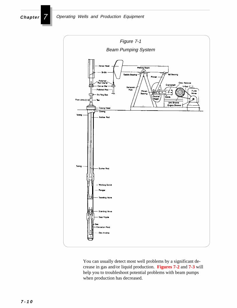
7 Operating Wells and Production EquipmentChapter
Figure 7-1
Beam Pumping System
7 - 1 0
You can usually detect most well problems by a significant de-crease in gas and/or liquid production. Figures 7-2 and 7-3 willhelp you to troubleshoot potential problems with beam pumpswhen production has decreased.

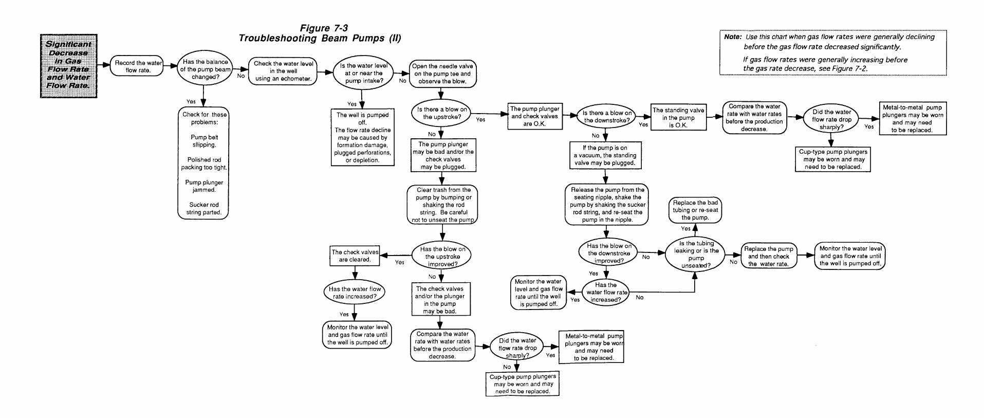
Troubleshooting Well and Equipment Problems
The guidelines below will help you further diagnose and correctproblems with the pump jack, prime mover, and rod string:
■■■■■ Make sure the pumping unit is balanced. You can checkthe balance two ways:
• Observe the difference in tension on the drive belt. If thetension on the upstroke is significantly different than thetension on the downstroke, then the unit is probably unbal-anced.
• Check the amperage on one leg of the pump motor usingamperage gauge. If the amperage on the upstroke is signifi-cantly different than the amperage on the downstroke, the unitis probably unbalanced.
■■■■■ If the pumping unit is out of balance:
• Make sure the pumping unit is properly aligned withthe wellhead.
• Make sure the rod guide is aligned vertically andlaterally with the tubing head.
• Adjust the counterbalance weights on the pumpingunit until the unit operates smoothly.
During early production, the water level in the annulus isusually high. Thus, the counter weights should be fairly closeto the pivot of the beam. As the water in the annulus falls,you may need to periodically adjust the counter weights awayfrom the pivot to compensate for the increased weight ofwater on the upstroke of the pump.
■■■■■ Reduce wear on the sucker rod string by:
• Periodically rotating the string 1/4 turn using a wrench or byinstalling an automatic rotator. This procedure will allow therods to wear more evenly.
• Running a short sucker rod, or “pony rod,” in the string.Then, whenever the string is pulled, re-run the string placingthe pony rod in a different location in the string. This proce-dure will prevent the string from continuing to wear in thesame places.
7 - 1 3
7 Operating Wells and Production EquipmentChapter
e
he
.t
-
7 - 1 4
T
The progressing cavity pump is probably the second most widelyused method of artificial lift for coalbed methane wells. Theprogressing cavity pump is used extensively in a number of areasin the Black Warrior Basin.The progressing cavity pump system consists of a surface driveunit, a sucker rod string, and a subsurface pump. The surface drivunit has an electric motor and sheaves which rotate the rod stringand the pump. The key components of the subsurface pump are trotor and the stator. The rotor is a single external helix with acircular cross-section, precision machined from high-strength steelThe stator is a double internal helix molded of an abrasion-resistanelastomer bonded within an alloy steel tube. As the rotor turnswithin the stator, cavities are formed which progress from thebottom, suction end of the pump to the top, discharge end, conveying the formation fluid up through the pump and into the tubing. A
• Running nylon rod guides on the rod string. You may run theguides on every rod joint or on every other joint, dependingon the amount of rod wear expected. Because the bottomportion of the hole is usually the most crooked, rods in thisarea usually wear the most.
■■■■■ To determine if the sucker rod string has parted, check theneedle valve on the pumping tee (wellhead assembly). Ifthere is no fluid production and the needle valve alternatesblowing and sucking air, then the rod string is likely parted.
■■■■■ Reverse the rotation of the motor every year by reversingthe electrical leads to the motor.This procedure will help the gears to wear more evenly.
■■■■■ Lubricate the pumping unit every 30-60 days or as specifiedby the manufacturer.
■■■■■ Change oil in the gearbox once a year. When you changethe oil, check for water in the bottom of the gearbox, andremove any water.
roubleshooting Progressing Cavity Pumps
he
Troubleshooting Well and Equipment Problems
continuous seal between the rotor and the stator helices keeps tfluid moving steadily, at a fixed rate directly proportional to therotational speed of the pump.
Progressing cavity pumps will burn up if they are not sub-merged in fluid. Therefore, you must periodically check thefluid level in the well using an echometer device. You can thenadjust the speed of the pump or change the size of the pump toensure that the pump remains submerged in fluid.
❈❈❈❈❈ Important
t-
t-
Many specialized techniques have been developed for troubleshooing electric submersible pumps. For information on these tech-niques, refer to Petroleum Engineering Handbook andThe Technology of Artificial Lift Methods, Vol. 2a . See Addi-tional Resources at the end of this chapter.
Figure 7-4 will help you to troubleshoot potential problems withprogressing cavity pumps when you notice production has declinedbelow expected levels.
For more information on progressing cavity pumps, see AdditionalResources at the end of this chapter.
The heat generated by electric submersible pumps can causesevere deposition of scale on the downhole pump. This scalecan eventually plug the pump and cause it to burn up. Becausescale deposition presents serious problems in some parts of theBlack Warrior Basin, electric submersible pumps may not bepractical in these areas.
Many specialized techniques have been developed for troubleshooing gas lift installations. For information on these techniques, referto Petroleum Engineering Handbook andThe Technology ofArtificial Lift Methods, Vol. 2a . See Additional Resources at theend of this chapter.
Troubleshooting Electric Submersible Pumps
Troubleshooting Gas Lift Installations
❈❈❈❈❈ Important
7 - 1 5
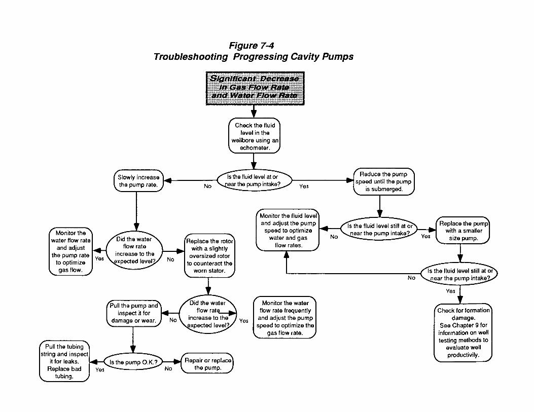
Troubleshooting Well and Equipment Problems
-
e of
Production Tubing
Regardless of the type of pump you select, the pump will eventually require repairs. The guidelines below will help you minimizeproduction downtime when a pump does go down.
■ Keep spare pumps on hand to avoid produc-tion downtime and workover rig time.Rebuilding pumps in the field is not as effective asinstalling a pump rebuilt in the shop.
■ When selecting people to service yourpumps, call only on those with experience inrepairing your particular type of pump.
■ For a plunger pump that is relatively new,you may be able to clean the check valves, replace rings orcups, and re-run the pump. However, you should sendolder pumps to the shop to make sure internal parts are notexcessively worn. The shop will check the tolerances ofinternal parts with a micrometer to make sure seals aregood and the pump is operating efficiently.
■ Be prepared to repair pumps more frequently during theearly production period of new wells. As production ofsolids decreases with time, pump repairs will likely becomefewer.
Leaks in the production tubing string can reduce pumping effi-ciency and decrease gas flow up the tubing/casing annulus. Onthe most common problems is connections that leak while underexternal or internal pressure. You can alleviate this problem byavoiding the following actions:
❖ Failing to sufficiently inspect each length of tubing and itsconnections
❖ Applying improper torque to the connections
Planning for Pump Repairs
7 - 1 7
7 Operating Wells and Production EquipmentChapter
7 - 1 8
❖ Failing to clean the threads properly before making up a con-nection
❖ Galling the threads by carelessly stabbing, making up toorapidly, using a damaged connection, over-torquing, or wob-bling pipe during makeup
❖ Dropping a string, even a very short distance
❖ Excessively making up and breaking out connections
❖ Mishandling tubing during transportation or at the well site
To extend the life of tubing strings at the Rock Creek project, when-ever a string is pulled, it is run back in the well in the reverse order.Thus, joints that were located near the top of the string end up nearthe bottom. This procedure prevents the sucker rod string fromwearing excessively in the same locations.
You can achieve the same goal by running a pup joint of tubing inthe string, and changing the location of the pup joint whenever youpull the tubing string.
Detecting Tubing LeaksIf you suspect a leak in the tubing string, you can use the simpleprocedure below to detect with reasonable certainty whether the tubinghas a major leak.
1. Check the pressure on the annulus.
2. Check the pressure on the needle valve on the pumping T.
3. If the pressure on the annulus and on the pumping T are thesame, or if both are on vacuum, the tubing likely has a leak.
To distinguish a tubing leak from other possible well problems, referto Figures 7-2 and 7-3.
To detect tubing leaks when you pull the tubing string, check forobvious cuts or holes, but also look for telltale water stains on the
are
y
to
e
an
n
s
Troubleshooting Well and Equipment Problems
outside of the tubing. Such stains often evidence small leaks that otherwise difficult to detect.
At the Rock Creek project most tubing leaks have been observed inthe lower portion of the tubing string because the wellbore is usuallmore deviated near the bottom. Wellbore deviation problems, andthus the number of tubing leaks, generally increase with depth.
To ensure trouble-free operation of instruments and meters used measure flow, you should prevent fines from entering the gatheringsystem. If gas carries even a small amount of fines, the velocity of thgas will quickly abrade or plug turbine meters and orifice plates.
Operating experience at the Rock Creek project has shown that you csignificantly reduce maintenance costs by removing fines at thewellhead before they can move into the collection system. You caeffectively control fines by installing a very fine mesh in-line filter atthe wellhead. A screen will protect downstream equipment, such aorifice meters, turbine meters, etc.
Surface Piping
of solids in vessels or their components. The guidelines below mayhelp you prevent many of the plugging problems caused by solids:
■■■■■ Periodically clean out the separator.If you observe sludge in the bottom of the separator, clean outthe vessel immediately.
■■■■■ Make sure check valves on separators areworking properly.When a check valve is working properly, you should hear aclicking sound as fluid passes through the valve.
■■■■■ Periodically flush out dump valves and check the valve seatsto make sure they seal properly. Also check the floatmechanism to make sure it operates properly.If the float is not cleaned regularly, it can stick and cause theseparator to overflow liquid into the gas line.
Separation EquipmentMost problems with separation equipment are caused by deposition
7 - 1 9
7 Operating Wells and Production EquipmentChapter
7 - 2 0
The gas compressor is perhaps the single most important equip-ment in a coalbed methane field. Because coalbed methane isproduced at such low pressures (1/2 - 30 psi in the Black War-rior Basin), it will not flow naturally into the pipeline. Thus,without an effectively operating compressor, you simply areunable to sell coalbed methane gas.
Compared to gas compression in conventional gas fields,coalbed methane gas compression is simpler in some ways.Because coalbed gas is approximately 98% methane, it containsno heavy hydrocarbons, which can damage compressor valves.
Be prepared to flush flowlines and collection lines withwater if you flow back a well that has been acidized. Theacid can loosen accumulated sludge in lines and causeplugging of downstream equipment.
■■■■■ Periodically check vacuum breakers in water lines to makesure the seat is clean so it will operate properly.If the seat is not clean, you may see water flowing out of theorifice in the vacuum breaker.
■■■■■ Periodically check drips to make sure they are not plugged.Check the float mechanism in automatic drips to make sureit is not stuck.During colder weather or after well stimulations, you may needto check drips more frequently because of the greater amountof water in the gas stream.
These additional guidelines below will help you to maintain thesurface piping system:
■■■■■ Periodically flush out surface flowlines and collection lineswith water to prevent buildup of sludge in the lines. Youcan often detect buildup of sludge by a pressure increase atthe wellsite pump used to move water through the collec-tion line.
▲▲▲▲▲ Caution
Gas Compressors
Gas Compressors
The greatest challenge in compressing coalbed methane is effec-tively removing water from the gas before compressing it. You cansolve this problem by selecting proper gas dehydration equipment.For information on selecting compressors and compressor equip-ment, refer to Chapter 6.
To ensure your compressor operates efficiently and continuously,you must practice a consistent maintenance program. The bestmaintenance program is probably the one recommended by thecompressor manufacturer. However, as you gain experience withyour field, you will likely learn additional maintenance practicesthat prove useful as well.
Compressor operators in the Black Warrior Basin generally followtwo separate maintenance schedules - an engine maintenanceschedule and a compressor maintenance schedule. They havefound the maintenance guidelines below especially effective inpreventing compressor problems:
■■■■■ Change the compressor oil about every 6 months. Changeoil filter every 1000 hours of operation.
■■■■■ Change the engine oil and filter every 1000 hours of opera-tion (approximately every 42 days).
■■■■■ Check the tolerance of engine valves to detect wear.By monitoring valve wear, you can estimate when downtime willbe required for engine repair. This forecasting will help you tocoordinate other necessary field repairs.
■■■■■ Torque the bolts which anchor the engine to its pad to main-tain proper alignment of the engine and the compressor.
■■■■■ Plan maintenance work so that all necessary work can beperformed at the same time to reduce downtime and wellshut-ins.
Maintaining the Compressor Engine
Maintaining the Compressor
7 - 2 1
7 Operating Wells and Production EquipmentChapter
7 - 2 2
■■■■■ Send a sample of the used compressor oil to a testing labora-tory to have it analyzed for contaminants.Contaminants in the oil, such as metal particles, may indicate thewearing and potential failure of internal components or leakingseals or gaskets.
■■■■■ Check the tightness of all external bolts on the compressorevery 1000 hours of operation. Tighten any loose bolts to theirproper torque.The constant vibration of the unit during operation can cause boltsto loosen.
■■■■■ Check the tolerance of compressor valves to detect wear aboutevery 3 months. At the same time, check the tolerance of therider bands on the pistons to detect wear.
■■■■■ Inspect the operation of relief valves monthly for safety.
The first step in preventing compressor failure is to install properequipment. For information on selecting compressors and compres-sor equipment for coalbed methane production, refer toChapter 6.
❖ ❖ ❖
Additional Resources
e
Additional Resources
Brown, K.E., "The Technology of Artificial Lift Methods, Volume2a,” Penwell Publishing Company, Tulsa (1977).
American Petroleum Institute, “Recommended Practice for Care andUse of Subsurface Pumps,” API RP 11AR, Third Edition, Wash-ington, DC (June 1989).
American Petroleum Institute, “API Specification for SubsurfacePumps and Fittings, ” API Spec 11AX, Seventh Edition, Dallas(June 1979).
Klein, S.T., Robbins & Myers, Inc. “The Progressing Cavity Pump inCoalbed Methane Extraction,” SPE Paper 23454, presented at th1991 SPE Eastern Regional Meeting, Lexington, Kentucky (October 22-25).
Society of Petroleum Engineers, “Petroleum Engineering Hand-book,” Richardson, Texas (1987).
7 - 2 3
8 Treating and Disposing ProducedWater
tedinginl caning the
ngionsire-ingter-
uld
op-
ment of a coalbed methane project. Some operators have initiaprojects and invested great time and money in drilling and completwells, but initially failed to sell any gas because of problems disposing produced water. Because water treatment and disposarepresent a large portion of daily operating costs, improper plannof this operation may result in unexpected costs which can impaireconomics of an otherwise profitable project.Water disposal problems often stem from not carefully investigatithe character of the produced water, treatment and disposal optavailable, the costs of the various options, and the regulatory requments that govern those options. A geological and engineerevaluation at the outset of the project can help prevent many warelated problems.
This chapter provides an overview of the main issues you shoconsider in developing a plan to manage produced water.
• Characteristics of Coalbed Methane Produced Water
• Regulations and Permitting for Water Disposal
• Considerations for Designing a Water Disposal System
• Methods for Treating and Disposing Produced Water
M anaging produced water is critical to the successful devel
Chapter 8 Treating and Disposing Produced Water
8 -
nd
a
In the Black Warrior Basin, gas usually begins to flow from a well1-30 days after dewatering has begun. Some wells, though, mayrequire pumping for several weeks or months to initiate methaneflow. Within the first month of a well’s life, water productionusually decreases by as much as 70%-90% of initial rate beforestabilizing to a slow decline. At some point, this decline normallyreaches a plateau for the rest of the well’s life. The time requiredto reach a steady water rate depends on the size of the reservoir athe well spacing. The larger the reservoir and the greater the wellspacing, the longer will be the dewatering period .
Characteristics of Coalbed Methane Produced Water
The rate of water removal from a coalbed methane well usuallydepends on geologic features, formation permeability, completionmethods, and the size of the pumps used. Water production from typical degasification well is usually greater at the start of pumpingand decreases gradually as the seam is dewatered. This waterproduction scenario appears to apply to wells that produce bothinitial high and low volumes of water (Kuuskraa and Brandenburg,1989; Simpson, 1989).
Varying qualities and quantities of water are co-pro-duced with methane gas. Many factors affect thequality of produced waters; however, the type anddepth of coal seams have the greatest influence. Ingeneral, waters produced from deeper coals appear tobe more mineralized than waters from shallow coals,which are more likely to have hydraulic connections
with less mineralized shallow groundwaters (Burkett, Hall, andMcDaniel, 1991).
The quality of water produced from coalbed reservoirs varieswidely from region to region. In some areas, the quality of theproduced water is comparable to that of drinking water. Theprincipal constituent influencing the quality of coalbed methanewaters is the concentration of total dissolved solids (TDS), whichincludes the concentration of chlorides. Total dissolved solidsconcentrations range from 500 to 27,000 mg/l in waters generatedin the eastern United States, and from 200 to 4,000 mg/l in thewestern United States (Lee-Ryan et al., 1991).
2
.
.
Characteristics of Coalbed Methane Produced Water
Scale from Coalbed Methane WaterScale is the product of precipitation and crystallization of mineralsfrom produced water. The formation of scale in the wellbore and inproduction facilities can restrict flow and damage equipment.
The factors that affect deposition of scale are:
❖ Mingling of incompatible waters
❖ Contact time
❖ Temperature change
❖ Pressure drop
❖ Evaporation
❖ Agitation
❖ pH
One or more of these factors can cause scale deposition in theformation matrix, fractures, perforations, wellbore, downhole pumps,tubing, casing, flowlines, and water disposal systems.
In the Black Warrior Basin, scale is frequently found in downholepumps and it has been observed on perforations by downhole cameraIn most cases, this scale is caused by pressure drop and agitationScaling can cause serious production declines; however, the calciumcarbonate scaling in the Black Warrior Basin has been removed bypumping an HCL acid treatment with an iron sequestering agent.
In some cases, scale may also form outside casing and in the inducedfractures. Scale inside fractures can severely restrict gas flow, and isdifficult to remove.
The composition of scale depends on the composition of the watersthat produce them. The most common scale deposits found inconventional oil fields are calcium carbonate, gypsum, barium sulfate,and sodium chloride. In the Black Warrior Basin, you are most likelyto encounter calcium carbonate scale.
Calcium Carbonate Scale
Calcium carbonate scale is usually caused by a change in pressurewhich releases CO2
from bicarbonate ions(HCO3-1). When the CO2
is released from solution, the pH increases, the solubility of dissolved
8 - 3
Chapter 8 Treating and Disposing Produced Water
rtedse
8 - 4
carbonates decreases, and the more soluble bicarbonates are conveto less soluble carbonates. Calcium carbonate scale exhibits thecharacteristics:
❖ Scaling increases with increased temperature
❖ Scaling increases with increased pH
❖ Scaling increases with increased contact time
❖ Scaling increases with increased turbulence
❖ Scaling increases with water agitation
Calcium carbonate scaling will decrease as the total salt content ofwater (excluding Ca+ ions) increases to a concentration of 120 g ofNaCl per 1000 g of water. Further increases in NaCl concentrationwill decrease CaCO3 solubility and thus cause scaling to increase.
Gypsum ScaleGypsum scale is composed of calcium sulfate. Gypsum scaleexhibits these characteristics:
❖ Scaling increases with a pressure decrease
❖ Scaling increases with water agitation
❖ Scaling is not affected by a pH of 6-8
Barium Sulfate ScaleBarium sulfate scaling is usually caused by the mingling of twounlike waters, one containing soluble salts of barium and the othercontaining sulfate ions. Barium sulfate scale exhibits these charac-teristics:
❖ Scaling increases with a temperature decrease
❖ Scaling increases with a pressure decrease
❖ Scaling increases as hydrates evaporate
Iron scales are often caused by corrosion products such as variousiron oxides and iron sulfide. Sulfate-reducing bacteria can produce
Iron Scales
le isoled toelyved
low a
ateratu-te
s:
,aleale
ed.
inard
se
Characteristics of Coalbed Methane Produced Water
hydrogen sulfide, which reacts with iron in solution or with steelsurfaces to form iron sulfide. If oxygen is introduced to a system,it can react with iron to form a precipitate or with steel surfaces toform an oxide coating.
Predicting the Scaling Tendency of WaterThe tendency of coalbed methane produced water to cause scausually discovered through experience in an area. Though downhwater samples (recovered at reservoir conditions) can be analyzepredict downhole scaling characteristics, this type of analysis is rarperformed in coalbed methane operations because of the cost involin obtaining samples at reservoir pressure and temperature.
The analysis of water samples taken at the surface does not alaccurate prediction of downhole scaling. However, you may havesurface sample analyzed to approximate the tendency of a producedwater to create calcium carbonate scale. In general, produced wwill have a tendency to create scale if the calcium carbonate supersration of the water is greater than 10 percent of the bicarbonaalkalinity content.
Identifying Scale
You can identify the various types of scale by using these method
X-Ray DiffractionThe most common method for identifying scale, X-ray diffractioninvolves directing a beam of X-rays onto a powdered sample of sccrystals. Because each crystalline chemical compound in the scdiffracts X-rays in a characteristic manner, the scale can be identifiThis method requires the least amount of sample.
Chemical AnalysisIn this method, samples of scale are crushed and then dissolvedchemical solution. The elements are then analyzed by standtitration and precipitation techniques.
EffervescenceThis method is used to identify calcium carbonate (CaCO3) scale. Ifa sample is CaCO3, it will bubble when you drop hydrochloric acid(HCl) on it. However, this test may not work if the sample containiron sulfide or iron carbonate. The odor of sulphur indicates thpresence of sulfide scale.
8 - 5
Chapter 8 Treating and Disposing Produced Water
8 -
Removing ScaleOperators in the Black Warrior Basin have used both mechanicaland chemical methods to remove scale. The most common me-chanical method is reperforating and/or running a bit and scraperthrough the perforations. The most successful chemical treatmentmethod is pumping HCL acid with an iron sequestering agent.
Preventing Scale
Regulations and Permitting for Water DisposalIn the Black Warrior Basin of Alabama, the operation of coalbedmethane fields is regulated by the State of Alabama Oil and Gas Board(OGB). The OGB issues permits for drilling of all coalbed methanewells, and regulates site maintenance, wellbore configuration andproduction procedures.
Production waters are generally regulated and managed according tothe specific disposal method used. For example, disposal of watersinto wells, often practiced in the conventional gas industry, is regu-lated under the Safe Drinking Water Act via the Underground Injec-tion Control Program. In contrast, waters produced in the coalbedmethane industry, which usually are discharged to surface watersbecause of the shallow coal horizons and the relatively fresh waters,require a NPDES (National Pollution Discharge Elimination System)permit under the Clean Water Act. This permit is issued by the
In the Black Warrior Basin, an effective method forpreventing scale is to pump scale inhibitors in fracturingtreatments. Fracturing service companies can recommend aninhibitor for your application. If you encounter a serious scaleproblem, you may consider continuously treating for scale downthe annulus.
Before pumping any chemical into a well, make sure the chemi-cal is tested to ensure it is compatible with the formation waterand that it is non-damaging to the coal. Make sure also thatthe chemical can be handled under the project’s regulatorydischarge permit (i.e., NPDES, etc.)
For more information on the chemistry of coalbed methane waters,refer to Additional Resources at the end of this chapter.
▲▲▲▲▲ Caution
6
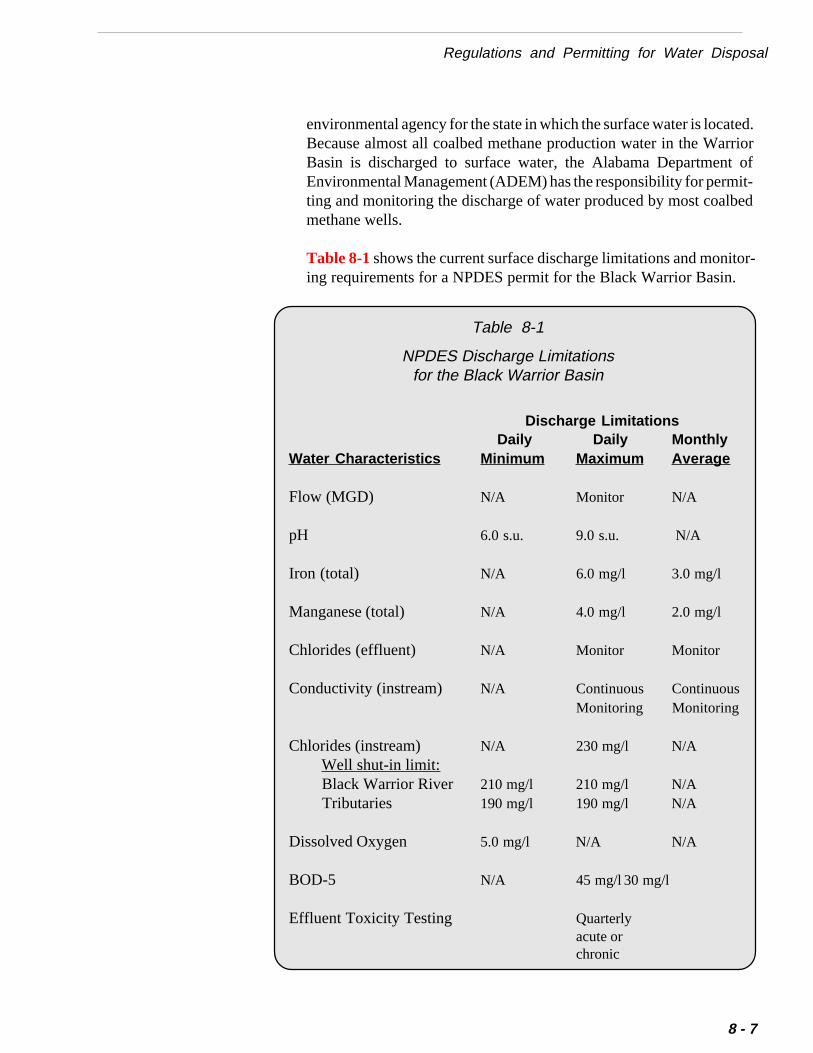
ted.riort ofit-ed
or-
Regulations and Permitting for Water Disposal
Discharge Limitations Daily Daily Monthly
Water Characteristics Minimum Maximum Average
Flow (MGD) N/A Monitor N/A
pH 6.0 s.u. 9.0 s.u. N/A
Iron (total) N/A 6.0 mg/l 3.0 mg/l
Manganese (total) N/A 4.0 mg/l 2.0 mg/l
Chlorides (effluent) N/A Monitor Monitor
Conductivity (instream) N/A Continuous ContinuousMonitoring Monitoring
Chlorides (instream) N/A 230 mg/l N/A Well shut-in limit: Black Warrior River 210 mg/l 210 mg/l N/A Tributaries 190 mg/l 190 mg/l N/A
Dissolved Oxygen 5.0 mg/l N/A N/A
BOD-5 N/A 45 mg/l 30 mg/l
Effluent Toxicity Testing Quarterlyacute orchronic
environmental agency for the state in which the surface water is locaBecause almost all coalbed methane production water in the WarBasin is discharged to surface water, the Alabama DepartmenEnvironmental Management (ADEM) has the responsibility for permting and monitoring the discharge of water produced by most coalbmethane wells.
Table 8-1 shows the current surface discharge limitations and moniting requirements for a NPDES permit for the Black Warrior Basin.
Table 8-1
NPDES Discharge Limitationsfor the Black Warrior Basin
8 - 7
Chapter 8 Treating and Disposing Produced Water
8
For information on discharge regulations and permitting require-ments in your area, contact the state oil and gas agency and envi-ronmental agency in the area.
Coalbed methane wells can produce large amounts of water as theinitial reservoir pressure is reduced. They then typically showfairly rapid decline in water rates and produce for an extendedperiod at a constant low water rate.
Considerations for Designing a Water DisposalSystem
To design an effective and economical water disposal system, youfirst must consider the environmental regulations and permittingrequirements for water disposal in your area. Once you understandthese restrictions, you can begin evaluating the field criteria thatwill influence your selection of a treatment and disposal system.
To design the system, you will need to know or estimate these fiveparameters:
• Production start-up schedule
• Water flow rates from each well
• Variations in flow rates over the life of the project
• Water quality
• Assimilative capacity of the discharge stream or river
Production Start-Up ScheduleThe first step in determining field disposal requirements is toprepare a schedule of estimated production start-up dates for eachof the planned wells. This schedule, which is based on drilling andcompletion schedules, will help you in estimating the total waterrate over the life of the field. The timing of initial well productioncan significantly influence the amount of water that must be treatedand disposed at any given time.
Water Flow Rates From Each Well
- 8
),
ter
.
Visan
W
g/l
ned
ial
toit.
Considerations for Designing a Water Disposal System
You can estimate water flow rates using a variety of techniques.You can incorporate permeability values from wells into a hydro-logic model. You can also predict rates using a reservoir modeldesigned for coalbed methane reservoirs.
Some operators in the Black Warrior Basin use a more field-ori-ented approach to estimate water flow rates from wells that havebeen drilled but not yet produced. While drilling the well, theyclosely monitor the drilling pits to gauge the rate of water influxfrom each water zone penetrated. After drilling to total depth (TDthey clean out the wellbore by injecting compressed air at TD forseveral hours while monitoring water returns at the surface.Though this technique is used primarily to determine the size ofpump needed for the well, you may also use it to approximate wadisposal requirements for individual wells. You cannot use thismethod if there are any water bearing sands open to the wellbore
ariations in Flow Rates Over the Life of the ProjectJust as important as initial flow rates and the timing of new wells the variation in water flow rates over the life of the project. You cuse reservoir simulations or flow rate histories from nearby offsetwells to estimate water production profiles for individual wells.
ater QualityThe principal constituent influencing the quality of coalbed meth-ane waters is the concentration of total dissolved solids (TDS),which includes the concentration of chlorides. Total dissolvedsolids concentrations range from 500 to 27,000 mg/l in watersgenerated in the eastern United States, and from 200 to 4,000 min the western United States (Lee-Ryan et al., 1991).
Other constituents in coalbed methane waters likely to requiretreatment include biochemical oxygen demand (BOD) and totaliron. Typically, the concentration of dissolved oxygen must beincreased before disposal.
The quality of the total produced water stream will determine thetype of discharge method you can use (these methods are explailater in this chapter). For example, in Alabama, water producedfrom coalbed methane wells can be treated like any other industror municipal waste stream. Thus, if the water meets permit stan-dards, surface discharge of the water is allowed. To discharge ina surface water, you must apply for and receive an NPDES perm
8 - 9
Chapter 8 Treating and Disposing Produced Water
to
r
Mnd-fgeueafy
ep-le,nd
k
ers
8 -
This permit will allow discharge into streams as long as the dis-charge is monitored and remains within permit requirements.
Assimilative Capacity of the Discharge Stream or RiverAssimilative capacity is the maximum concentration of chloridesthat the state regulatory agency allows an operator to discharge ina stream. Assimilative capacity is determined based on historicalstream flow during drought conditions. Currently, the state ofAlabama defines the maximum assimilative capacity for chloridesas 230 mg/l. However, when the in-stream chlorides concentrationreaches 190 mg/l, the wells must be shut in.
For a detailed discussion of how these five parameters can beincorporated into a comprehensive water management model, refeto the paper by Burkett, McDaniel, and Hall (See AdditionalResources at the end of this chapter).
ethods for Treating and Disposing Produced WaterDeveloping a plan to manage produced waters requires an understaing of the character of the produced water, the working range oavailable processes, the cost of the various options, and a knowledof treatment constraints for existing environmental regulations. Yoshould also contact the appropriate regulatory agency in your arbefore finalizing plans for water treatment to ensure the plans satisthe current regulations.
Economic development of coalbed methane requires an effectivproduction water management strategy. To ensure that field develoment proceeds in an environmentally sound manner and on scheduyou should develop a comprehensive plan to manage the treatment adisposal of produced water. Such a plan for a field in the BlacWarrior Basin is described by Burkett, Hall, and McDaniel (SeeAdditional Resources at the end of this chapter).
Treatment and disposal options for coalbed methane produced watin the Black Warrior Basin can generally be divided into threecategories:
• Treating Water and Disposing on the Surface• Disposing Water in Disposal Wells• Disposing Water after Well Stimulations
1 0

T
ion.romr-sing
eamayron-
s.
al
s
d
partet
Methods for Treating and Disposing Produced Water
reating Water and Disposing on the Surface
In areas where regulations allow its use, treatment of producedwaters and surface disposal is the lowest cost water disposal optThis method requires an NPDES permit, which can be obtained fthe state or federal Environmental Protection Agency (EPA). Suface disposal has become the method most widely used for dispocoalbed methane produced waters in the Black Warrior Basin ofAlabama because of the water chemistry, sustained seasonal strflow, and porous soil. Though regulations on surface disposal mbe tightened in the future, this method currently provides an envimentally acceptable and cost-effective option where applicable.
Currently, NPDES permitting approves two types of surface dis-posal: direct land application and controlled discharge into stream
Direct Land Application
Applying produced water directly to the land typically involvesmoving water from the well to a nearby area of vegetation via aburied flowline, and dispersing the water on the ground with acommon lawn sprinkler head.
Though direct land application is probably the least costly disposmethod, the requirements for this option are relatively strict. Forexample, the State of Alabama requires that the total dissolvedsolids (TDS) concentration does not exceed 2000 mg/l, and thewater must be applied in such a way that there is no soil erosionrunoff into nearby streams.
Land application was used initially in the Brookwood and OakGrove coalbed methane fields in Alabama. As deeper coal seamwere drilled and produced, waters with higher concentrations ofTDS were encountered. Because the higher TDS levels precludecontinuing land application, the operators switched to controlledstream disposal.
Recent environmental regulations in Alabama require that a two-technical evaluation be performed before any new water dischargpermit will be issued. Phase one of this evaluation covers currensoil and hydrology conditions in the area of operation. Phase twocovers engineering aspects of the field operation, including fieldequipment and production facilities.
8 - 1 1
Chapter 8 Treating and Disposing Produced Water
r
8 - 1 2
Other states may or may not have similar permitting requirements.For current regulations in your area of operation, contact the stateenvironmental agency.
Controlled Discharge into Streams
Currently, surface stream dilution for water disposal requires thatthe instream chloride concentration remains below 230 mg/l andthat the iron concentration in the discharge water has a monthlyaverage no greater than 3 mg/l. The operator is required to monitothe water upstream and downstream of the discharge point and tocomply with daily limits for various effluent characteristics.
s
Most operators in the Black Warrior Basin treat coalbed methaneproduced water by pooling the water into a treatment pond, aerat-ing the water to remove iron, allowing solids to settle out, and thendischarging the water into a stream through an EPA-approveddiffuser nozzle. These water systems also contain a storage pondto hold water during periods of low stream flow when dischargevolumes must be reduced. Figure 8-1 shows the flow of water in atypical water disposal system in the Black Warrior Basin.
Because the aeration treatment oxidizes the water and separatessuspended solids, it increases dissolved oxygen levels and reducedissolved iron (and other trace metals, if present), biochemicaloxygen demand (BOD), volatile organic compounds, if present,and total suspended solids (TSS).
f
hens,
ega-tion.
acityondsque
Methods for Treating and Disposing Produced Water
Figure 8-1
Typical Water Disposal System in the Black Warrior Basin
❈ ❈ ❈ ❈ ❈ Important In cases where stream flows are much greater than the flow odischarged fluids, relatively high amounts of chlorides can bedischarged with little increase in the chloride concentration in tstream. In streams with low flow or with seasonal flow variatioproduced water discharge may be limited.
Unlike TDS concentration and other permit parameters that ardetermined by instream concentrations, the limit of iron or mannese in the water is based on its discharge (effluent) concentraAt the Rock Creek Project, two lined ponds with capacities of34,000 gal and 400,000 gal provide treatment and holding capin case the produced water exceeds regulatory limits. These palso allow aeration of the water to precipitate iron. This techni
8 - 1 3
Chapter 8 Treating and Disposing Produced Water
la
beheto
s
m
ts
8 - 1 4
d
ed
n
has successfully reduced iron concentrations to meet the disposapermit requirements. This type of system may require some extrstorage capacity in case of occasional upsets in the system.
Some of the highest iron measurements in treatment ponds may caused by algae growth. Algae accumulations on the bottom of tpond can collect settling iron precipitates. Often this algae floats the surface, bringing the precipitated iron with it. When watersamples are collected, this algae may be collected inadvertently,skewing iron measurements far above true levels. Experience haalso shown that agitating the water by aeration can inhibit growthof floating algae accumulations.
Algae growth is a function of the pH of the water. During hotsummer weather, accelerated growth of algae in smaller settlingponds may elevate the pH level of water in the pond. You canusually reduce the pH to permit levels by shading the pond fromthe sun.
When stream disposal is used, provisions must be made to allowyear-round operation of the field even during periods of low streaflow. For example, many streams in the Black Warrior Basinapproach near-zero flow during the summer and fall months. Inmost cases, storage of produced water is the only alternative toshutting-in wells. Storage, however, can be impractical for fieldswith high water rates unless the technical and economic constrainof large-scale temporary storage can be overcome. Toward thisobjective, Luckianow and Hall present an informative review ofselected storage alternatives, design requirements, constructionconstraints, regulatory requirements, and cost data (see AdditionalResources at the end of this chapter).
Safety of In-Stream DisposalBecause many producers in the Black Warrior Basin have obtainepermits to discharge into streams, several studies have been per-formed to assure environmental safety. A key conclusion of thesestudies was that stream discharges could safely occur at levelsspecified by permits without adversely affecting biota (O'Neill etal, 1989; Drottar et al, 1989; O'Neill et al, 1991a; O'Neill et al,1991b). In these studies, in-stream chlorides levels were increasuntil significant changes in biota were observed. These changesdid not occur until chlorides exceeded 593 mg/l, a value more tha200% greater than the current maximum permitted concentration(O'Neill et al, 1989).
Methods for Treating and Disposing Produced Water
n aresal-
tes-there
edend
ofay
teivepitals.oval
aycial
ater
Disposing Water in Disposal WellsFew injection wells are currently in use in the Black Warrior Basibecause most formations in this area are of low permeability andnot suitable for injection. Most attempts to complete water dispowells in the Black Warrior Basin have been unsuccessful and significantly more expensive than surface disposal methods.
Injection wells are more commonly used for water disposal in stawhere coalbed methane produced water is treated like a conventional oil and gas waste stream, where surface stream flow is nosufficient year round to assimilate produced waters, and where tare formations that will accept the necessary disposal volumes.
Disposing Water After Well StimulationsAfter fracturing a well, you will need to dispose the water producback. The method you use to treat and dispose the water will depprimarily on the regulations in the state where you operate.
For example, in the Black Warrior Basin of Alabama, if the quality the frac water meets state specifications for land application, you mdispose it by spraying it directly on vegetated land. To facilitatreatment of frac water, you should keep drilling pits open to recethe initial production from fractured wells. You can use the lined at the well site for aeration and/or mixing water treatment chemicYou should check with the state regulatory agencies to obtain apprto keep the pits open for initial production.
If you cannot treat the water to meet permit discharge criteria, you mneed to transport the water via a permitted truck to commerinjection wells for disposal.
The primary constituents you should check in produced fracture ware listed below:
❖ Chlorides concentration
❖ pH
❖ Dissolved oxygen concentration
❖ Biochemical oxygen demand (BOD)
8 - 1 5

Chapter 8 Treating and Disposing Produced Water
8 - 1 6
If-ve
Occasionally, after a well is stimulated the concentration of totalorganic carbon, or BOD, can be higher than specifications allow. the well was shut-in for an extended period of time before production, any bacteriacide included with the fracture treatment may halost its effectiveness. Such fracture waters are often most effec-tively treated separately, rather than mixing them with the entirewater process stream.
As environmental issues continue to gain prominence, thetreatment and disposal of produced water will become anincreasingly sensitive operation. To ensure that your watertreatment and disposal practices satisfy state regulations, makesure you review and understand all relevant regulations .
❖ ❖ ❖
❈ ❈ ❈ ❈ ❈ Important
Additional Resources
,
il
a,
of
-
Additional Resources
Burkett, W.C., R. McDaniel, and W.L. Hall, “ The Evaluation andImplementation of a Comprehensive Production Water Manage-ment Plan,” Proceedings of the 1991 Coalbed Methane SymposiumTuscaloosa, Alabama (May 13-17).
Drottar, K.R., D.R. Mount, and S.J. Patti, 1989, “Biomonitoring ofCoalbed Methane Produced Water from the Cedar Cove, AlabamaDegasification Field,” Proceedings of the 1989 Coalbed MethaneSymposium, The University of Alabama, Tuscaloosa, Alabama (Apr17-20).
Kuuskraa, V.A. and C.F. Brandenburg, “Coalbed Methane Sparks aNew Energy Industry,” Oil & Gas Journal, October 9, 1989.
Lee-Ryan, P.B., J.P. Fillo, J.T.Tallon, and J.M. Evans, “Evaluation ofManagement Options for Coalbed Methane Produced Water,” Pro-ceedings of the 1991 Coalbed Methane Symposium, TuscaloosAlabama (May 13-17).
Luckianow, B.J., “Economics of Production Water Storage,” Pro-ceedings of the 1991 Coalbed Methane Symposium, The University Alabama, Tuscaloosa, Alabama (May 13-17).
Luckianow, B.J., and W.L. Hall, “ Water Storage Key Factor inCoalbed Methane Production,” Oil & Gas Journal, Mar 11, 1991.
O’Neill, P.E., S.C. Harris, and M.F. Mattee, 1989, "Stream Monitor-ing of Coalbed Methane Produced Water from the Cedar CoveDegasification Field, Alabama,” Proceedings of the 1989 CoalbedMethane Symposium, The University of Alabama, Tuscaloosa, Alabama (April 17-20).
8 - 1 7
Chapter 8 Treating and Disposing Produced Water
8 - 1 8
e
O’Neill, P.E. et al, 1991a, “Long Term Biomonitoring of a ProducedWater Discharge from the Cedar Cove Degasification Field, Ala-bama,” GRI Topical Report, GRI-90/0233, (January).
O’Neill, P.E. et al, 1991b, “Long Term Biomonitoring of a ProducedWater Discharge from the Cedar Cove Degasification Field, Ala-bama,” Proceedings of the 1991 Coalbed Methane Symposium, ThUniversity of Alabama, Tuscaloosa, Alabama (May 13-17).
Schraufnagel, R.A., “Coalbed Methane Production,” in “Hydrocar-bons from Coal,” American Association of Petroleum Geologists(AAPG), Tulsa, Oklahoma, not yet published.
Schraufnagel, R.A., and S.D. Spafford, “Multiple Coal SeamsProject Progress Report,” Quarterly Review of Methane FromMultiple Coal Seam Technology, V 7 N 3 (March).
Simpson, T.E., “Environmental Overview, Coalbed Methane GasDevelopment in Alabama, 1984-1989,” Dames & Moore, 1989.

9 Testing the Well
t
d
T o determine the economic feasibility of a coalbed methane well,you must evaluate the production potential of the coal seams beforefracturing and producing the well. You can obtain the reservoir datafor this evaluation from open hole logs, cores, and pressure transientests. (For a list of information you can obtain from log and coreanalysis, refer to Chapter 3.) If the evaluation indicates the coal seamhas potential for economical production, the well should be fracturedand placed on production. After placing the well on production, youshould check the gas and water rates periodically using well tests toensure the well is producing at an optimum level.
This chapter explains methods for obtaining the reservoir data needeto assess the productive potential of coalbed methane wells. You willfind information to help you in:
• Performing Pressure Transient Tests
• Evaluating Production from Multiple-Seam Wells
Chapter 9 Testing the Well
d
-
d
reee
nin
s
e
ek
9 - 2
Performing Pressure Transient Tests
Pressure transient well tests can provide important information forassessing the production potential and economic feasibility of coalbemethane wells. This information includes estimates of reservoirpressure, permeability, wellbore damage, wellbore storage, porositycompressibility product, as well as fracture length and conductivity inhydraulically fractured wells. Pressure transient tests can also be useto estimate the distance to a reservoir discontinuity.
The two most important properties for predicting the performance ofa coalbed methane reservoir are permeability and reservoir pressuwith respect to desorption pressure. You can obtain both of thesparameters from well tests. To be productive, coal seams must havsufficient permeability to allow withdrawal of enough water to lowerthe reservoir pressure below the desorption pressure of the coal. Whereservoir pressure drops below the desorption pressure, gas will begto flow from the coal to the wellbore.
Well tests may be performed on either single wells or multiple wells.Single-well tests are more commonly used and are usually lesexpensive than multiple-well tests. Multiple-well tests are used todetermine communication between wells, porosity-compressibilityproducts, and the orientation of permeability.
The slug test is particularly suited to coalbed methane wells becausno surface flow-control or downhole pumping is required. Most othersingle well and multiple-well test methods require pumping from orinjecting into the well at a constant rate.
This section explains the most commonly used well tests for obtainingcoal reservoir properties and the procedures used at the Rock Creproject to perform them. These tests are:
• Slug Tests
• Injection/Fall-off Tests
• Interference Tests
• Pressure Buildup Tests
eg
Performing Pressure Transient Tests
Slug TestsSlug tests are the simplest and least expensive tests. They arecommonly used on coalbed methane wells because they can beperformed with a minimal amount of manpower and equipment.
A slug test involves the instantaneous injection or withdrawal of aspecific slug, or volume of water into or from the wellbore. Theincrease or decrease in wellbore pressure is then measured versus timuntil the pressure approaches the pressure measured before the sluwas initiated. The results of the slug test can be matched with type-curves developed by Ramey and others (1975) to determine perme-ability with respect to both wellbore storage and skin effects.
Most slug tests used on coalbed methane wells are run by injecting aslug of fresh water into the wellbore rather than withdrawing a slug offluid from the wellbore.
The main advantages of the slug test are:
❖ Low cost
❖ Simple to design and perform
❖ Simple to analyze using type curve analysis
The only equipment needed to run a slug test is listed below:
❖ Workover rig to prepare the well for test (if required)
❖ Equipment to slug water into the wellbore (buckets ofwater, a small pump, or a vacuum truck)
The main disadvantages of the slug test are:
❖ Not valid for two-phase flow
❖ Reservoir must be under-pressured
❖ Limited radius of investigation
❖ Duration of test is long
❖ Difficult to interpret reservoir heterogeneities
9 - 3
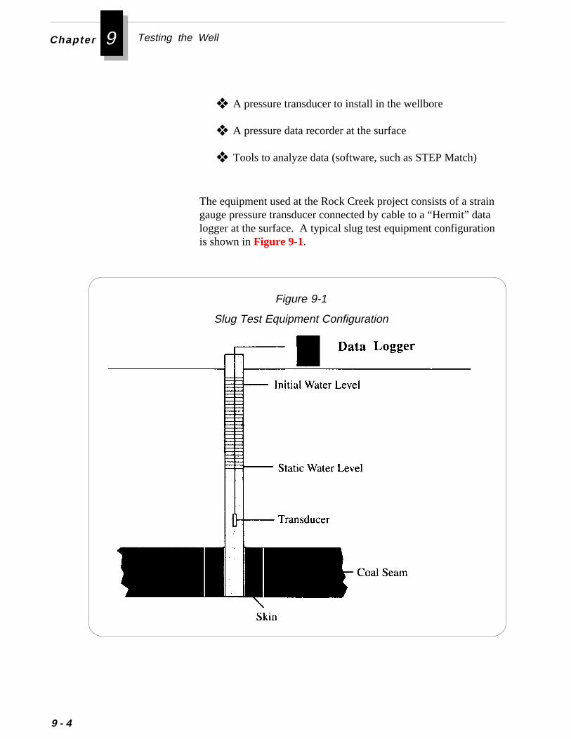
Chapter 9 Testing the Well
traindatation
9 - 4
❖ A pressure transducer to install in the wellbore
❖ A pressure data recorder at the surface
❖ Tools to analyze data (software, such as STEP Match)
The equipment used at the Rock Creek project consists of a sgauge pressure transducer connected by cable to a “Hermit” logger at the surface. A typical slug test equipment configurais shown in Figure 9-1.
Figure 9-1
Slug Test Equipment Configuration
rtrg
thatil-
str, for
e
Performing Pressure Transient Tests
Designing a Slug Test
The three main considerations in designing a slug test are:
❖ Tubular Size
❖ Tubular Configuration
❖ Method of Slugging
Tubular SizeThe most important consideration is the diameter of the tubing ocasing through which the well will be slugged. The duration of the tesis directly proportional to the square of the radius of the tubing ocasing used. The duration of the test increases with increasindiameters because as the tubing size increases, the volume of water must flow into the coal seam increases. Consequently, the permeabity of the coal seam directly affects the duration of the test. Tominimize the time required to test the well, you can use the smalletubing size that is economically and operationally feasible. Howevedecreasing the test time also decreases the radius of investigationthe test.
You can estimate the minimum test duration for a unique type curvmatch by using the equation below:
t = 43,700 µ re2 , hrs kh
where:
t = minimum duration of the test, hrs
k = permeability of the formation, md
h = thickness of the zone, ft
µ = viscosity of the slugged fluid, cp
re = internal radius of the tubing or casing through whichthe well is slugged, ft
9 - 5
Chapter 9 Testing the Well
.
r
t
9 - 6
Performing a Slug Test
Tubular ConfigurationIf you conduct the slug test down the casing, you will not need anyadditional equipment. However, if you conduct the test down thetubing string, you must run a packer on the tubing to isolate the annulusIf you do not seal off the annulus, the benefit of using a small tubingstring (shorter test duration) will be negated.
Method of SluggingTo perform a slug test, you must load a volume of water into the tubingor casing. The methods most commonly used to load the slug of wateinto the tubing or casing are:
❖ Dumping pails of water into the tubing
❖ Pumping the water with a chemical pump
❖ Pumping the water with the small pump on a vacuum truck
The method you use to load the well depends on the permeability of thecoal and on the volume of water needed for the slug. The higher thecoal permeability, the more rapidly you can load the water slug.
You can estimate the volume of water needed for the slug if you knowthe static fluid level for the coal seam you are testing. The maximumvolume of water required for the slug is the volume needed to fill thetubing or casing from the static fluid level to the surface.
The procedures used at the Rock Creek project to perform a slug tesare explained below:
1. Isolate the zone of interest.If more than one zone is open to the wellbore during a slug test,you may not obtain any useful data about either zone. The zoneof interest should be isolated using bridge plugs and packers ifnecessary.
2. If the well is slugged through a tubing/packer assembly, testthe tubing/casing annulus to make sure the packer is notleaking.
,ll
s
e
-
,re
t
d
Performing Pressure Transient Tests
Fluid leaking into the well from the annulus would require usingmultiple storage coefficients, which would make the test difficultto analyze. If perforated intervals are above the zone of interestyou may not be able to test the packer unless those zones wisupport a minimal amount of pressure.
An alternative method of determining that the packer is providingisolation is by pumping water into the annulus and monitoring thedownhole data recorder for a pressure response.
3. After installing the tubing/packer assembly, lower the pres-sure transducer into the wellbore.Place the transducer deep enough in the wellbore so that it remainbelow the fluid level throughout the test, but not so deep that thehydrostatic pressure of the fluid above the transducer exceeds thtool’s maximum pressure rating at any time during the test.
4. Allow the well time to equilibrate before beginning the slugtest.At the Rock Creek Project, Saulsberry et al have developed aspreadsheet program which can help you estimate the time required for the well to equilibrate and the equilibration pressure. Ifyou cannot wait the required time before beginning the slug testyou can begin the test and use the estimated equilibration pressuas the initial pressure before the slugged volume.
5. Inject a slug of water into the formation.At the Rock Creek project, it was learned that the best way to injecwater depends on the permeability and/or skin of the zone beingtested. For wells that do not take fluid rapidly, you can inject theslug by pouring buckets of water into the tubing. If a well is fairlypermeable, you may need to use a pump or a vacuum truck to loathe tubing with the slug of water.
6. Start the data recording equipment at the instant the slug ofwater is injected into the wellbore.The early time data of a slug test is important to the interpreta-tion of the pressure responses. To ensure that the early timedata is recorded, you may need two people to initiate the test.
9 - 7
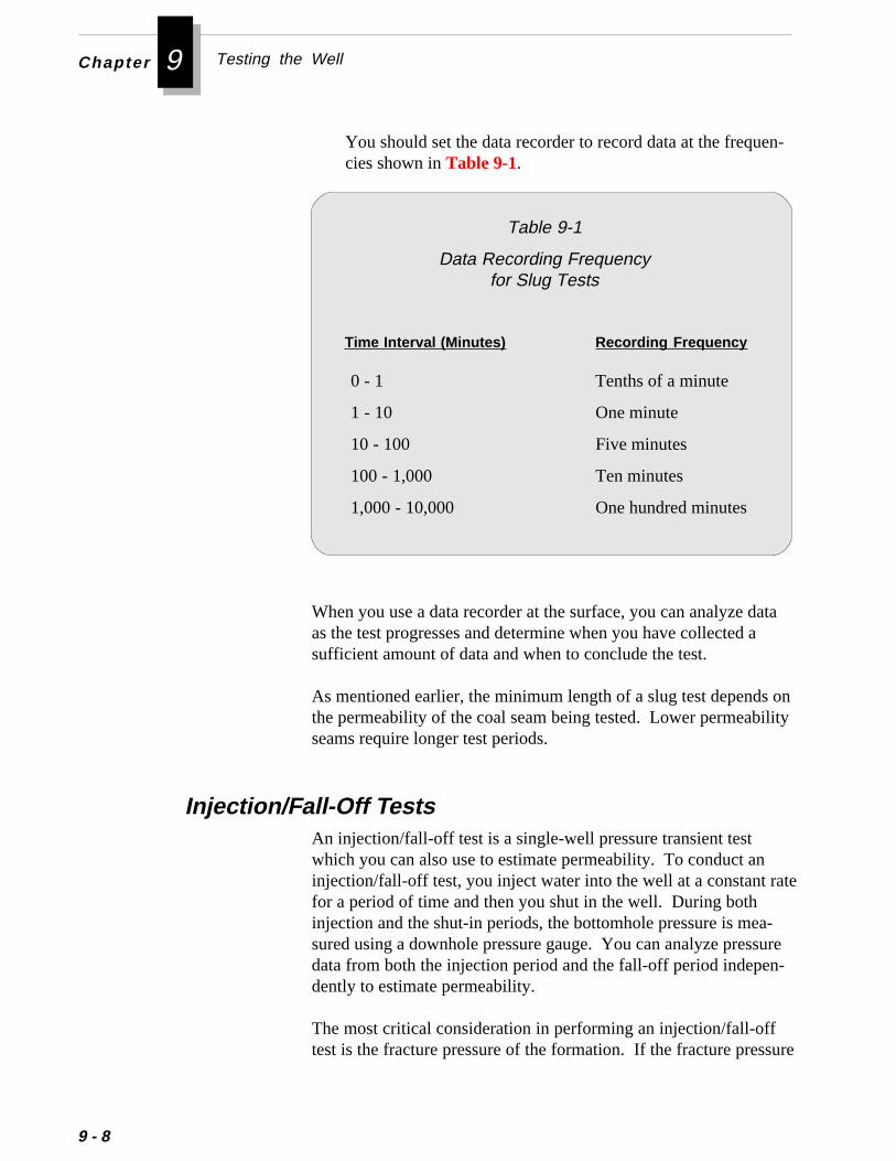
Chapter 9 Testing the Well
n-
ta
onity
te
-ure-
ure
9 - 8
You should set the data recorder to record data at the frequecies shown in Table 9-1.
Table 9-1
Data Recording Frequencyfor Slug Tests
Time Interval (Minutes) Recording Frequency
0 - 1 Tenths of a minute
1 - 10 One minute
10 - 100 Five minutes
100 - 1,000 Ten minutes
1,000 - 10,000 One hundred minutes
When you use a data recorder at the surface, you can analyze daas the test progresses and determine when you have collected asufficient amount of data and when to conclude the test.
As mentioned earlier, the minimum length of a slug test dependsthe permeability of the coal seam being tested. Lower permeabilseams require longer test periods.
An injection/fall-off test is a single-well pressure transient testwhich you can also use to estimate permeability. To conduct aninjection/fall-off test, you inject water into the well at a constant rafor a period of time and then you shut in the well. During bothinjection and the shut-in periods, the bottomhole pressure is measured using a downhole pressure gauge. You can analyze pressdata from both the injection period and the fall-off period independently to estimate permeability.
The most critical consideration in performing an injection/fall-offtest is the fracture pressure of the formation. If the fracture press
Injection/Fall-Off Tests
ta
te.
es
Performing Pressure Transient Tests
is exceeded during the injection period, the injection pressure dais meaningless. The late-time data from the shut-in period couldpossibly be useful if the induced fracture closes soon enough forsome of the pressure fall-off to measure the natural coal seamresponse. However, a permeability estimate derived from the latime data should be considered the upper bound for permeability
The main advantages of the injection/fall-off test are:
❖ Can provide a larger radius of investigation
❖ Relatively quick to perform
❖ May be used for post-fracture analysis
The disadvantages of this type of test are:
❖ Relatively expensive
❖ Difficult to perform in low permeability coal seams becausvery low injection rates must be maintained (sometimes alow as 0.04 GPM).
The equipment needed to perform a slug test are:
❖ Workover rig to install the tubular equipment downhole
❖ Low rate pump
❖ Low rate water meter
❖ Supply of water
❖ Slickline (wireline) unit to install pressure gauges anddownhole shut-in tool
❖ Pressure gauges
❖ Downhole shut-in tool
9 - 9
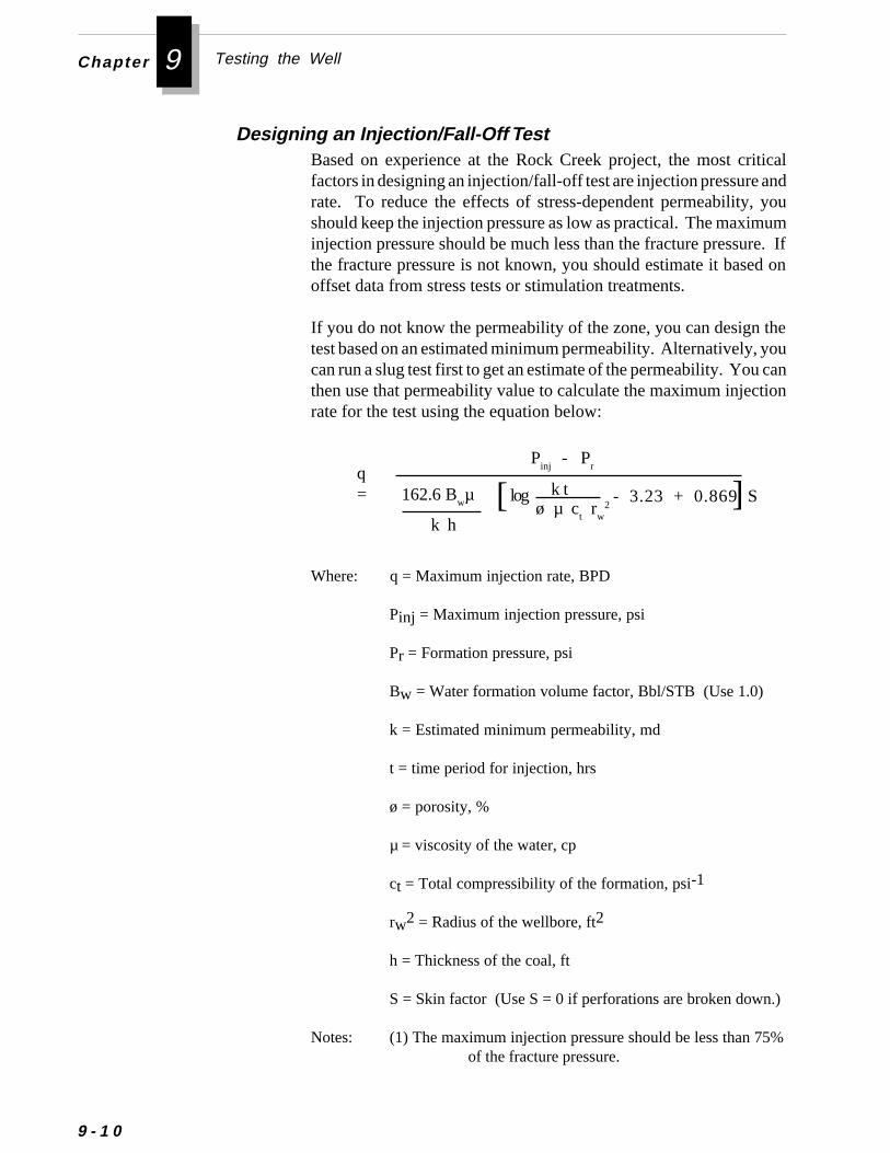
Chapter 9 Testing the Well
9 - 1 0
Designing an Injection/Fall-Off Test
Where: q = Maximum injection rate, BPD
Pinj = Maximum injection pressure, psi
Pr = Formation pressure, psi
Bw = Water formation volume factor, Bbl/STB (Use 1.0)
k = Estimated minimum permeability, md
t = time period for injection, hrs
ø = porosity, %
µ = viscosity of the water, cp
ct = Total compressibility of the formation, psi-1
rw2 = Radius of the wellbore, ft2
h = Thickness of the coal, ft
S = Skin factor (Use S = 0 if perforations are broken down.)
Notes: (1) The maximum injection pressure should be less than 75%of the fracture pressure.
Based on experience at the Rock Creek project, the most criticalfactors in designing an injection/fall-off test are injection pressure andrate. To reduce the effects of stress-dependent permeability, youshould keep the injection pressure as low as practical. The maximuminjection pressure should be much less than the fracture pressure. Ifthe fracture pressure is not known, you should estimate it based onoffset data from stress tests or stimulation treatments.
If you do not know the permeability of the zone, you can design thetest based on an estimated minimum permeability. Alternatively, youcan run a slug test first to get an estimate of the permeability. You canthen use that permeability value to calculate the maximum injectionrate for the test using the equation below:
- 3.23 + 0.869 Sq=
k h
k tø µ c
t r
w2[ log162.6 B
wµ
Pinj
- Pr
]
Performing Pressure Transient Tests
(2) The time period should be based on the injection period(e.g., 24 hours for a 24-hour injection period).
The fall-off portion of the test normally yields the most useful infor-mation. To increase the amount and quality of information obtainedduring this period, you can install a downhole shut-in plug afterinjection to reduce the wellbore storage effects.
Before beginning an injection/fall-off test, you should make thefollowing preparations:
1. Contact the service company who will perform the test andfind out what equipment they will provide and what equip-ment you need to provide.The service company will usually supply water, pumps, and allmetering equipment for the job.
2. Prepare the well for the test.This step includes installing the appropriate bottomhole assemblythat will hold the pressure gauges and the downhole shut-in plug(if one is to be used).
A typical bottomhole assembly would include:
❖ Joint of tubing with bull plug on bottom
❖ Perforated sub
❖ Packer
❖ Seating nipple for the downhole shut-in plug
❖ Tubing to the surface
As an alternative to the joint of tubing on bottom, you can installthe perforated sub with a bull plug on bottom and the joint of pipein between the perforated sub and the packer. This configurationis a matter of preference.
Preparing for an Injection/Fall-Off Test
9 - 1 1
Chapter 9 Testing the Well
ve
d
9 - 1 2
To install the pressure gauges, there must be sufficientdistance between the end of the tubing (bull-plugged joint)and the seat nipple. To ensure you have sufficient clearanceto set the shut-in plug after the injection period, find out thelength of the tandem pressure gauges from the servicecompany representative .
3. Make sure the surface connections include:
❖ Full opening ball valve large enough to allow the downholeshut-in plug to pass through. This valve will allow the wellto be shut-in after the injection is concluded. This valvemay be needed because the plug might need pressure aboit to hold it in place (depending on the pressure below theplug). The plug is designed to withstand a certain differen-tial pressure.
❖ Tapped nipple with pressure gauge. This gauge will be useto monitor pressure on the tubing during the shut-in period.
4. Check and record the volume and quality of water onlocation.You must keep an accurate record of volume of water pumpedinto the well during the test.
Water containing debris can prevent the plug from properlyseating in the nipple.
5. Pressure test the injection lines to the maximum allowablesurface pressure.
◆◆◆◆◆ If no valve is installed between the injection line and theconnection to the tubing, you should observe the injectionlines for leaks during the job.
◆◆◆◆◆ If you observe a leak during the job, attempt to fix the leakwhile continuing to inject, if possible.
❈❈❈❈❈ Important
Once you begin injection, you should not discontinueinjecting unless safety or environmental regulations arethreatened. Water that is not fresh should never be allowedto drain onto the ground.
◆◆◆◆◆ If you continue injecting with a leaking line, collect and
❈❈❈❈❈ Important
▲▲▲▲▲ Caution
e
o
f
li-the
Performing Pressure Transient Tests
measure the volume of leaked water so you can determinthe actual injection volume.
Performing an Injection/Fall-Off TestThe procedures used at the Rock Creek project to perform a slugtest are explained below:
1. Run the tools in the hole.
◆◆◆◆◆ If the tubing is not new, you should make a dummy run intthe hole with sinker bars (sized as close to the O.D. of thetools as necessary) on slickline.
2. Allow the gauges to sit in the well for a least one hour tomeasure the current pressure trend (if any) in the reser-voir.
3. Fill the tubing with water as quickly as possible, unless youare testing the well at a pressure below the hydrostaticpressure.Make sure the needle valve on the lubricator is open to allowair and/or gas to escape as the tubing is filled.
4. After the tubing is filled, fill the lubricator with water.Loosen the top nut on the lubricator so pressure will bleed ofthe lubricator while it fills with water.
As the lubricator is filled with water, the injection pressure wilincrease due to the increasing hydrostatic column in the lubrcator. The maximum pressure increase due to the height of lubricator depends on the height of the lubricator above theinjection point. This pressure can be calculated using theequation below.
ÐP = h x ð x 0.052 , psi
where:h = height of the lubricator above the tubing, ft
ð = density of the water, lb/gal
9 - 1 3
Chapter 9 Testing the Well
9 - 1 4
5. Measure and record the volume of water left on locationwhen injection is completed.
6. Calculate the average injection rate during the test usingthe equations below:
Injection Volume = Initial Volume - Final Volume - TubingVolume - Lubricator Volume
Average Injection Rate = Injection VolumeInjection Time
Remember to take into account the volume of water used tofill the tubing and the lubricator.
The calculated average injection volume should be close to thevalue measured by the water meters on location.
7. After concluding the injection period, set a tubing plug inthe seating nipple.
8. Pressure up the tubing above the plug to make sure theplug is set.Because most plugs will withstand a limited amount of differ-ential pressure, the pressure that is left on the tubing while thewell is shut-in should exceed the final injection pressure beforethe plug was set.
9. Wait for the well pressure to fall off.
10. After the pressure has fallen off completely, retrieve thedownhole shut-in tool with a wireline retrieving tool andretrieve the downhole pressure gauges.
ce by
inu-gw
oir-
-the
.- or
are:
ods
Performing Pressure Transient Tests
11. Analyze the pressure data.The bottomhole pressure data recorded during the injectionportion of the test is often erratic (even though injection ratesmay have been stable) and is therefore difficult to analyze.The data obtained during the fall-off portion of the test usuallyprovides the most useful information.
Interference Tests
An interference test is a multiple-well test withan active well and one or more observation wells. In an interferentest, a pressure transient is applied to the formation to be testedeither injecting fluid into or withdrawing fluid from the active well.The pressure response to the applied stress is then monitored contously in the active well and all of the observation wells. In designinan interference test, it is important to select an injection rate loenough not to fracture the formation.
Multiple-well tests generally yield more information about a coalbedmethane reservoir than single-well tests. In addition to static reservpressure and intrinsic permeability, multiple-well tests can also provide directional permeability, porosity-compressibility product, leakage from an adjacent aquifer through a semi-permeable barrier, or location of a no-flow or constant-head boundary within the coal seamMultiple-well tests are most useful for determining directional permeability. Interference tests can be analyzed using either type curvesthe straight-line method.
The main advantages of interference tests over other tests methods
❖ Generally tests a larger portion of the coalbed reservoir
❖ Provides more information about the reservoir
The main disadvantages of interference tests over other tests methare:
❖ Expensive❖ Lengthy test period❖ Sometimes difficult to analyze
9 - 1 5
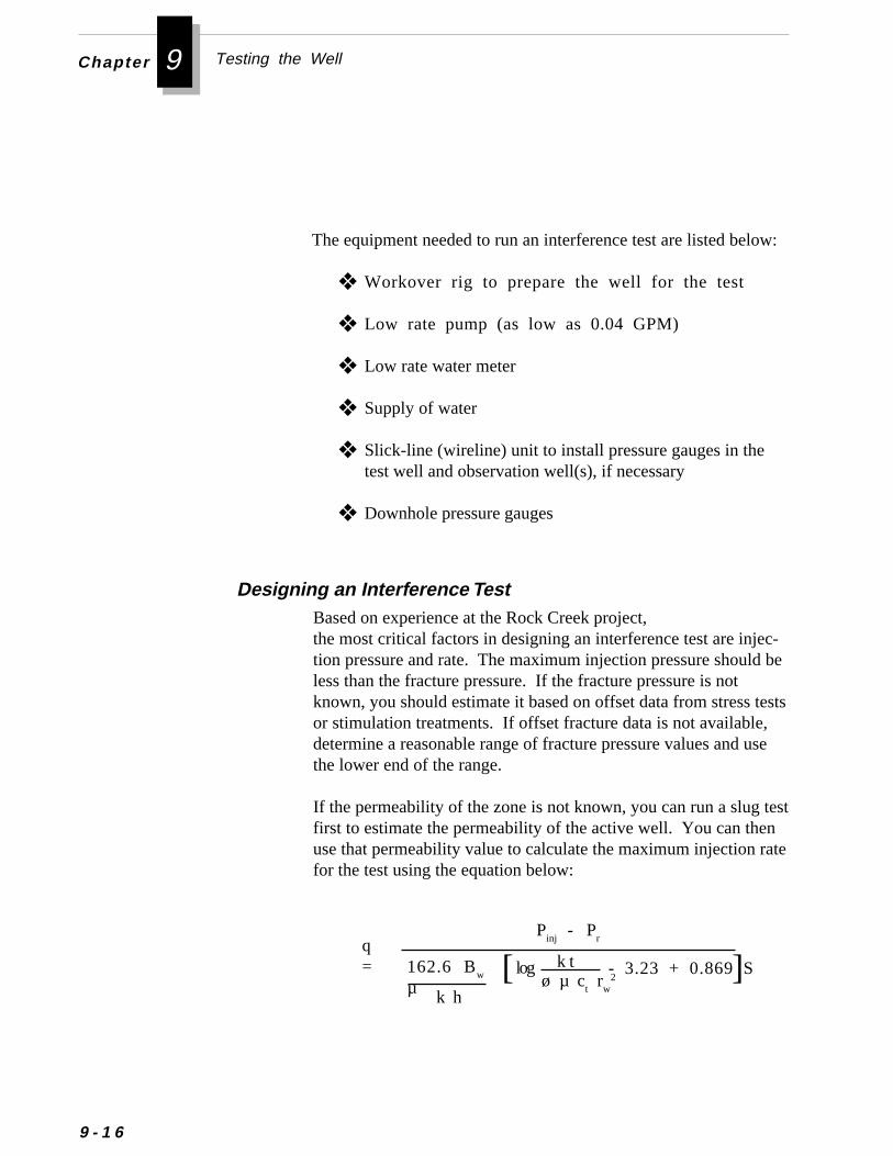
Chapter 9 Testing the Well
c- be
ests
se
est
te
9 - 1 6
w:
Based on experience at the Rock Creek project,the most critical factors in designing an interference test are injetion pressure and rate. The maximum injection pressure shouldless than the fracture pressure. If the fracture pressure is notknown, you should estimate it based on offset data from stress tor stimulation treatments. If offset fracture data is not available,determine a reasonable range of fracture pressure values and uthe lower end of the range.
If the permeability of the zone is not known, you can run a slug tfirst to estimate the permeability of the active well. You can thenuse that permeability value to calculate the maximum injection rafor the test using the equation below:
Designing an Interference Test
The equipment needed to run an interference test are listed belo
❖ Workover rig to prepare the well for the test
❖ Low rate pump (as low as 0.04 GPM)
❖ Low rate water meter
❖ Supply of water
❖ Slick-line (wireline) unit to install pressure gauges in thetest well and observation well(s), if necessary
❖ Downhole pressure gauges
- 3.23 + 0.869 Sq=
k h
k tø µ c
t r
w2[ log162.6 B
w
µ
Pinj
- Pr
]
%
Performing Pressure Transient Tests
ng
ll
lyug
Where: q = Maximum injection rate, BPD
Pinj = Maximum injection pressure, psi
Pr = Formation pressure, psi
Bw = Water formation volume factor, Bbl/STB (Use 1.0)
k = Estimated minimum permeability, md
t = time period for injection, hrs
ø = porosity, %
µ = viscosity of the water, cp
ct = Total compressibility of the formation, psi-1
rw2 = Radius of the wellbore, ft2
h = Thickness of the coal, ft
S = Skin factor (Use S = 0 if perforations are broken down.)
Notes: (1) The maximum injection pressure should be less than 75of the fracture pressure.
(2) The time period should be based on the injection period(e.g., 24 hours for a 24-hour injection period).
Before beginning an interference test, you should make the followipreparations:
1. Contact the service company who will perform the test andfind out what equipment they will provide and what you needto provide.The service company will usually supply water, pumps, and ametering equipment for the job.
2. Prepare the well for the test.This step includes installing the appropriate bottomhole assembthat will hold the pressure gauges and the downhole shut-in pl(if one is to be used).
Preparing for an Interference Test
9 - 1 7
Chapter 9 Testing the Well
9 - 1 8
A typical bottomhole assembly would include:
❖ Joint of tubing with bull plug on bottom
❖ Perforated sub
❖ Packer
❖ Seating nipple for the downhole shut-in plug
❖ Tubing to the surface
The surface connections should include:
❖ A ball valve on the injection tubing so that the well canshut-in after the injection is concluded
❖ A tapped nipple with a pressure gauge so that pressure onthe tubing can be monitored during the shut-in period
Performing an Interference TestThe procedures used at the Rock Creek project to perform an interfer-
ence test are explained below:
1. Run the tools in the hole.If the tubing is not new, you should make a dummy run into thehole with sinker bars (sized as close to the O.D. of the tools asnecessary) on slickline.
2. Fill the tubing with water as quickly as possible.Make sure the needle valve on the lubricator is open to allow airand/or gas to escape as the tubing is filled.
3. Measure and record the volume of water left on location wheninjection is completed.
4. Calculate the average injection rate during the test using theequations below:Remember to take into account the volume of water used to fillthe tubing and the lubricator.
e
l
Performing Pressure Transient Tests
The calculated average injection volume should be close to thvalue measured by the water meters on location.
Injection Volume = Initial Volume - Final Volume - TubingVolume - Lubricator Volume
Average Injection Rate = Injection VolumeInjection Time
5. Continue injecting until you observe a pressure response inoffsets wells.
6. After concluding the injection period, continue to monitorthe pressures in the test well and in each observation welluntil all pressures have stabilized.
7. After all pressures have stabilized, run in the hole andretrieve the pressure gauges.
8. Analyze the pressure data.
Pressure buildup testing of coalbed methane wells is difficult toperform because almost all coalbed methane wells are on artificialift. Artificial lift equipment prevents installation of downholepressure gauges while the well is flowing. To install gauges on alift well, you would first have to shut-in the well and remove thelift equipment from the wellbore. This procedure would cause theloss of valuable early time data. To perform a successful builduptest, two alternative methods have been tried.
Pressure Buildup Tests
9 - 1 9
Chapter 9 Testing the Well
9 - 2 0
Using a Well Sounder
The first method is the use of an automatic well sounder (AWS).This method has been used on pumping oil wells for many years.It simply involves connecting an AWS machine to the annulus ofthe well to be tested. After the sounder is installed, it is set torecord some data points under stabilized pumping conditions.Then the well is shut in. The sounder continues to record the fluidlevels and converts them to pressures until the pre-programmedtime ends or the sounder is stopped manually.
The advantages to this method are:
❖ Easy to operate
❖ Relatively inexpensive (no rig work required)
The disadvantages to this method are:
❖ The accuracy of pressure measurement is no greater thanthe fluid column weight across the length of one joint oftubing
❖ Two-phase flow may complicate the analysis
❖ Wellbore storage effects are usually significant
❖ Pressure readings may be inaccurate if the fluid level isbelow a set of perforations
The other technique for performing a buildup test was developed at theRock Creek project. This method involves measuring the pressure atthe surface rather than downhole. You can use this method only onwells that have a working fluid level below the perforations of theinterval to be tested.
This technique is based on the premise that surface pressure can beaccurately extrapolated to the bottomhole pressure as long as the fluidlevel remains below the perforations. Thus, the bottomhole pressurecan be estimated during the shut-in period until the fluid level risesabove the perforations.
Using the Rock Creek Technique

suresuresingwen” typeTheuentt” is
lineins.
e
-
s
if
-
le
Evaluating Production from Multiple-Seam Wells
The only equipment required for this technique is an “In-Situ” prestransducer, “Bowen” wiper and a “Hermit” data recorder. The prestransducer is installed in the piping from the side outlet of the cahead. The cable for the pressure transducer is run through a “Bowiper rubber that can hold the low pressures observed during thisof test. The cable is then connected to the “Hermit” recorder. “Hermit” pressure recorder should be programmed to record freqearly time data. After all the equipment is connected, the “Hermistarted and within 10 seconds, the pumping unit is stopped, the flowvalve on the annulus is closed, and the pressure buildup test beg
The main advantages to this method are:
❖ Inexpensive
❖ Easy to run (no outside services required)
❖ Can be performed frequently
Evaluating Production from Multiple-Seam Wells
The limitations of this method are:
❖ Can only be used on wells with a working fluid level below thperforations
❖ Two-phase flow may occur in the formation, which complicates the analysis
To optimize production from any well, you should have procedurein place for predicting and identifying production trends. Whenproduction deviates from these trends, you must then determine your expectations of well performance were valid. If they arevalid, then you must determine if the well has any mechanicalproblems. For information on identifying and correcting mechanical problems with wells, refer to Chapter 6.
This section explains ways to evaluate the production from multipseams. It will introduce you to:
• Typical Coalbed Methane Production Decline Curves
9 - 2 1
Chapter 9 Testing the Well
9 - 2
e
irs.
d
e is
• Determining Production from Individual Seams in a Mul-tiple-Seam Well
• Recognizing Reservoir Problems
The production decline curves of coalbed methane wells are quitdifferent than those from conventional wells. This difference isrelated to the unique characteristics of coalbed methane reservoCoal seams contain natural fractures, or cleats, that are usuallysaturated with water. The methane gas in the seams is adsorbeonto the coal. To produce the gas, it must first be desorbed fromthe coal. This desorption occurs after enough water has beenproduced from the seam to reduce the pressure in the seam to thdesorption pressure of the coal. When the pressure in the seamat or below the desorption pressure, the gas will desorb from thecoal and flow through the cleats to the induced fracture andthrough the fracture to the wellbore. You can determine the des-orption pressure from core tests.
Typical Coalbed Methane Production Decline Curves
l.
o
n
.
Monitoring the production performance of a single-seam coalbedmethane well is much easier than monitoring a multiple-seam welWhen production is commingled from several zones, it is difficultto accurately determine production rates and pressures for indi-vidual seams. Many of the coalbed methane wells in the BlackWarrior Basin produce from three or more seams.
Determining Production from Individual Seams in aMultiple-Seam Well
Because water must be removed from the coal seam tlower the pressure, the initial production from a coalbed methanewell is water. After enough water has been produced to lower thepressure, gas production will begin. At this point water, productiowill often begin to decline. Figure 9-2 shows a typical productiondecline for coalbed methane wells in the Black Warrior Basin.During the production of a well, you should monitor fluid levelsand production rates to make sure the well is producing at anoptimum level. You should also attempt to keep the fluid levelbelow the coal seam and minimize backpressure on the wellhead
2
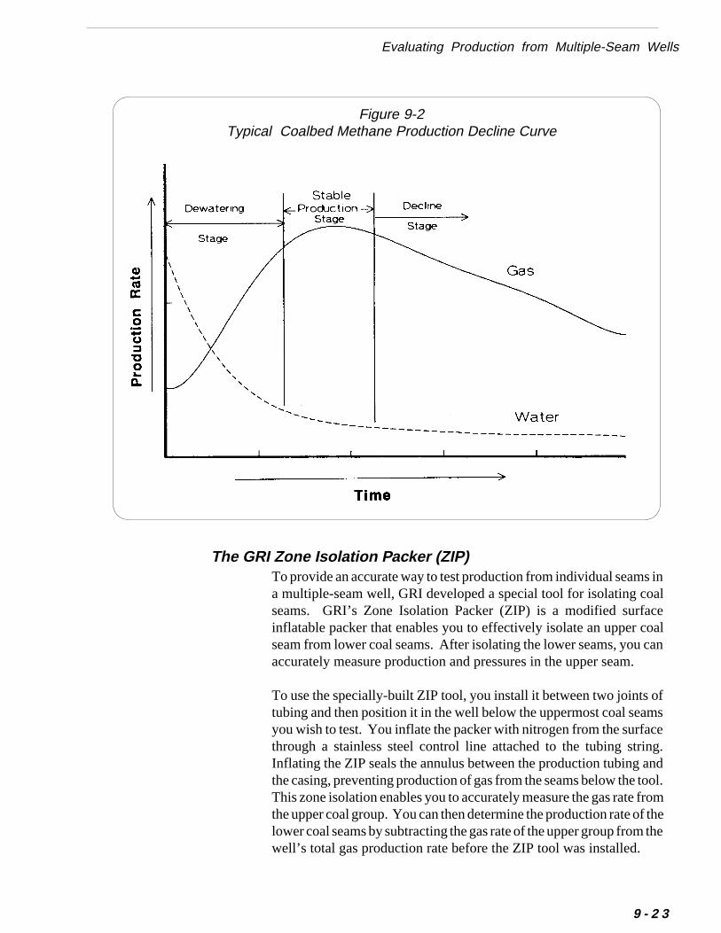
Evaluating Production from Multiple-Seam Wells
inlealan
fs
eg.ndol.omthethe
Figure 9-2Typical Coalbed Methane Production Decline Curve
To provide an accurate way to test production from individual seams a multiple-seam well, GRI developed a special tool for isolating coaseams. GRI’s Zone Isolation Packer (ZIP) is a modified surfacinflatable packer that enables you to effectively isolate an upper coseam from lower coal seams. After isolating the lower seams, you caccurately measure production and pressures in the upper seam.
To use the specially-built ZIP tool, you install it between two joints otubing and then position it in the well below the uppermost coal seamyou wish to test. You inflate the packer with nitrogen from the surfacthrough a stainless steel control line attached to the tubing strinInflating the ZIP seals the annulus between the production tubing athe casing, preventing production of gas from the seams below the toThis zone isolation enables you to accurately measure the gas rate frthe upper coal group. You can then determine the production rate of lower coal seams by subtracting the gas rate of the upper group from well’s total gas production rate before the ZIP tool was installed.
The GRI Zone Isolation Packer (ZIP)
9 - 2 3
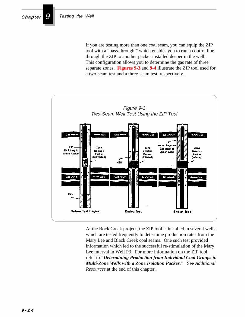
Chapter 9 Testing the Well
9 - 2 4
If you are testing more than one coal seam, you can equip the ZIPtool with a “pass-through,” which enables you to run a control linethrough the ZIP to another packer installed deeper in the well.This configuration allows you to determine the gas rate of threeseparate zones. Figures 9-3 and 9-4 illustrate the ZIP tool used fora two-seam test and a three-seam test, respectively.
Figure 9-3Two-Seam Well Test Using the ZIP Tool
At the Rock Creek project, the ZIP tool is installed in several wellswhich are tested frequently to determine production rates from theMary Lee and Black Creek coal seams. One such test providedinformation which led to the successful re-stimulation of the MaryLee interval in Well P3. For more information on the ZIP tool,refer to “Determining Production from Individual Coal Groups inMulti-Zone Wells with a Zone Isolation Packer.” See AdditionalResources at the end of this chapter.
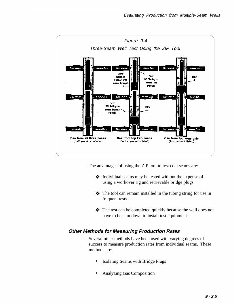
Three-Seam Well Test Using the ZIP Tool
Figure 9-4
not
se
Evaluating Production from Multiple-Seam Wells
The advantages of using the ZIP tool to test coal seams are:
❖ Individual seams may be tested without the expense ofusing a workover rig and retrievable bridge plugs
❖ The tool can remain installed in the tubing string for use infrequent tests
❖ The test can be completed quickly because the well does
Several other methods have been used with varying degrees ofsuccess to measure production rates from individual seams. Themethods are:
• Isolating Seams with Bridge Plugs
• Analyzing Gas Composition
Other Methods for Measuring Production Rates
have to be shut down to install test equipment
9 - 2 5
Chapter 9 Testing the Well
ell
fn
-
er
d if
-
9 - 2 6
This method is expensive and time consuming. To use thismethod, a workover rig is needed to install the retrievable bridgeplugs and to retrieve them later. Before beginning the test, the wmust be shut in to install the plugs, and the well must be pumpeddown to stabilize production rates.
You can use flowmeters, gradiomanometers, and temperaturesurveys to approximate the flow rates of individual perforatedintervals in the wellbore. Though this method has been improved
This method involves analyzing the composition of the total pro-duced water stream and then comparing it with the composition owater produced from individual coal seams. This method has beeused with some success to estimate the water production fromindividual coal seams.
As with comparing gas compositions, this method can be successful only if there are distinct differences in water chemistry betweenthe coal seams. Even if the differences are great, you can onlyestimate the water production from the individual seams. Youwould have to infer the gas production based on the premise thatthere is a reliable and consistent correlation between gas and watproduction in each coal group.
This method involves analyzing the composition of the total gasstream and then comparing it with the composition of gas producefrom individual coal seams. A study was conducted to determinegas production rates could be estimated accurately using gas composition analysis. This method was not successful because of therelatively small variations in the compositions of the coal seams.
Production Logging and Camera Surveys
Analyzing Water Composition
Analyzing Gas Composition
• Analyzing Water Composition
• Production Logging and Camera Surveys
Isolating Seams with Bridge Plugs
ll
e
Evaluating Production from Multiple-Seam Wells
over the years, you may still find it difficult to estimate productionrates from individual seams because many seams produce at ex-tremely low rates.
Camera surveys cannot be used to obtain quantitative productionestimates. However, you can use camera surveys to see whetherfluid is flowing into the wellbore, and if so, which intervals areproducing that fluid. For more information on production loggingtools and camera surveys, refer to Chapter 3.
Recognizing Reservoir ProblemsThe key to evaluating production performance is understandingwhy some wells in your coalbed methane field are good producersand why others are poor producers. Is it because of geological orreservoir conditions? Is it because of completion or stimulationtechnique? Or is it because of operational procedures? Mostlikely, some combination of these factors influences overall pro-duction performance.
Production tests may help you determine that each seam in the weis not producing at optimum rates. If you have eliminated thepossibility of mechanical problems with the artificial lift equipmentor surface equipment, then you must conclude the problem isassociated with the reservoir. Some of the most common coalbedmethane reservoir problems are:
• Scale Deposition in the Formation
• Insufficient Fracture Stimulation
• Depletion of the Coal Seam
Some of the coal seams in the Black Warrior Basin contain waterswith a high tendency for scaling. Scaling can occur in surfaceequipment and downhole equipment as well as in perforations andin the formation. Though you can easily observe scaling in equip-ment and in perforations (with a camera survey), you cannot ob-serve scaling in the formation. To determine if scaling has oc-curred in the formation, you must use pressure transient tests toassess formation damage. If formation damage exists, it could havbeen caused by scale. For information on the scaling tendency ofcoalbed methane produced water, refer to Chapter 8.
9 - 2 7

Chapter 9 Testing the Well
s.
fal
9 - 2 8
Poor production performance could also be caused by insufficientfracture stimulation of the coal seams or by depletion of the seamYou can diagnose these reservoir problems by analyzing pressuretransient tests and by simulating reservoir performance using oneof the commercially available computer models for coalbed meth-ane reservoirs.
To make well-informed production management decisions, youshould attempt to gather and analyze quality data from a variety oindependent sources. This practice will help ensure the operationas well as economic success of your coalbed methane project.
❖ ❖ ❖
a-
s
gy
h-
ey
Additional Resources
Additional Resources
Koenig, R.A., and R.A. Schraufnagel, “Application of the Slug Testin Coalbed Methane Testing,” Proceedings of the 1987 CoalbedMethane Symposium, The University of Alabama, Tuscaloosa, Albama (November 16-19).
Koenig, R.A. and P.B. Stubbs, ”Interference Testing of a CoalbedMethane Reservoir,” Proceedings of the 1986 Unconventional GaTechnology Symposium, Louisville, Kentucky (May 18-21).
McKee, C.R., “Well Testing,” GRI Coalbed Methane Workshop,Pittsburgh, Pennsylvania (February 6-7, 1989).
Rushing, J.A. et al, “Analysis of Slug Test Data From HydraulicallyFractured Coalbed Methane Wells,” SPE Paper 21492, Texas A&MUniversity/Society of Petroleum Engineers, SPE Gas TechnoloSymposium, Houston (January 23-25, 1991).
Rushing, J.A. et al, “Slug Testing in Multiple Coal Seams Intersectedby a Single, Vertical Fracture,” SPE Paper 22945, Texas A&MUniversity/Society of Petroleum Engineers, 1991 SPE Annual Tecnical Conference and Exhibition, Dallas (October 6-9).
Saulsberry, J.L., S.W. Lambert, and Dobscha, F.X., “DeterminingProduction from Individual Coal Groups in Multi-Zone Wells witha Zone Isolation Packer,” Proceedings of the 1991 Coalbed MethanSymposium, The University of Alabama, Tuscaloosa, Alabama (Ma13-16).
9 - 2 9
Appendix ASummary of Permitting Requirements
forDrilling a Coalbed Methane Well in Alabama
(State Oil and Gas Board of Alabama)
-
Summary of Permitting Requirements for Drilling aCoalbed Methane Well in Alabama
A summary of the permitting requirements of the State Oil and Gas Board of Alabamaare listed below:
Permit to DrillBefore you can spud a well in the State of Alabama, you must submit a Form OGBI (Application for Permit to Drill, Deepen, Convert, or Amend). This form must be accompanied by the following:
• Permit Fee
• Certified Survey Plat (Triplicate)
• Affadavit of Ownership or Control, Form OGB- 11.
• Bond, Form OGB-3 or OGB-4.
• Organization Report, Form OGB-5
This permit may not be approved until all other applicable environmental regulations havebeen approved by other agencies.
Drilling OperationsDuring drilling operations, an agent of the State Oil and Gas Board of Alabama(Board) must be notified and approval obtained prior to performing any of the follow-ing operations:
• Construction of any pit
• Spudding
• Setting surface casing
• Slotting casing
• Running intermediate or production pipe
• Cleaning
• Perforating
• Chemical treatment or fracturing
• Logging
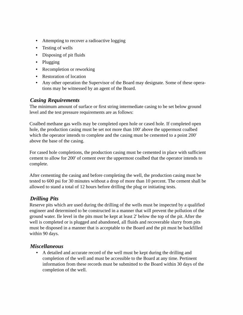
• Attempting to recover a radioactive logging
• Testing of wells
• Disposing of pit fluids
• Plugging
• Recompletion or reworking
• Restoration of location• Any other operation the Supervisor of the Board may designate. Some of these opera-
tions may be witnessed by an agent of the Board.
Casing RequirementsThe minimum amount of surface or first string intermediate casing to be set below groundlevel and the test pressure requirements are as follows:
Coalbed methane gas wells may be completed open hole or cased hole. If completed openhole, the production casing must be set not more than 100' above the uppermost coalbedwhich the operator intends to complete and the casing must be cemented to a point 200'above the base of the casing.
For cased hole completions, the production casing must be cemented in place with sufficientcement to allow for 200' of cement over the uppermost coalbed that the operator intends tocomplete.
After cementing the casing and before completing the well, the production casing must betested to 600 psi for 30 minutes without a drop of more than 10 percent. The cement shall beallowed to stand a total of 12 hours before drilling the plug or initiating tests.
Drilling PitsReserve pits which are used during the drilling of the wells must be inspected by a qualifiedengineer and determined to be constructed in a manner that will prevent the pollution of theground water. Ile level in the pits must be kept at least 2' below the top of the pit. After thewell is completed or is plugged and abandoned, all fluids and recoverable slurry from pitsmust be disposed in a manner that is acceptable to the Board and the pit must be backfilledwithin 90 days.
Miscellaneous• A detailed and accurate record of the well must be kept during the drilling and
completion of the well and must be accessible to the Board at any time. Pertinentinformation from these records must be submitted to the Board within 30 days of thecompletion of the well.
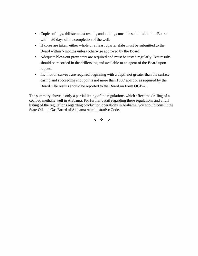
ts
he
• Copies of logs, drillstem test results, and cuttings must be submitted to the Board
within 30 days of the completion of the well.
• If cores are taken, either whole or at least quarter slabs must be submitted to the
Board within 6 months unless otherwise approved by the Board.
• Adequate blow-out preventers are required and must be tested regularly. Test resul
should be recorded in the drillers log and available to an agent of the Board upon
request.
• Inclination surveys are required beginning with a depth not greater than the surface
casing and succeeding shot points not more than 1000' apart or as required by the
Board. The results should be reported to the Board on Form OGB-7.
The summary above is only a partial listing of the regulations which affect the drilling of acoalbed methane well in Alabama. For further detail regarding these regulations and a fulllisting of the regulations regarding production operations in Alabama, you should consult tState Oil and Gas Board of Alabama Administrative Code.
v v v
Appendix BSummary of Permitting Requirements
forDrilling a Coalbed Methane Well in Alabama
(State Oil and Gas Board of Alabama)
1
QUALITY CONTROL GUIDELINESGAS RESEARCH INSTITUTE
QUALITY CONTROL AND JOB SUPERVISION GUIDELINESFOR STIMULATION TREATMENTS
INTRODUTION
Quality control is a key element in the successful implementation of any stimulation treat-
ment. Simply stated, attention to quality control is needed to ensure that the stimulation treat-
ment is pumped as designed. Often times, quality control is considered the responsibility of
the service company alone, but frankly, ensuring a successful job is the responsibility of both
the operator and the service company. Attention to detail by both the operator and the service
company and close cooperation between the two before, during, and after the job is certain to
increase the quality of service in any stimulation treatment.
The guidelines which follow this discussion should assist the engineer in the quality con-
trol and job supervision of stimulation treatments. The guidelines include a comprehensive
supervision checklist to remind the engineer of equipment needed for the job, safety concerns,
and questions to ask before, during, and after the job. The tables that follow the checklist
permit the engineer to prepare a complete summary of the job (injection rates, injection pres-
sures, fluid and proppant volumes, etc.), as well as an inventory of all products on location
before and after the treatment. An important responsibility of the stimulation engineer is to
obtain a reliable record of what actually occurred during the treatment; these guidelines and
tables should help meet this responsibility.
While these guidelines can be used for quality control and supervision of any stimulation
treatment, we have attempted to tailor them for use in Appalachian Basin reservoirs where
possible. While quality control problems are not unique to this area, proper job execution in
Appalachian Basin reservoirs is especially important due primarily to the smaller treatments
pumped routinely. Quality control on smaller, shorter treatments is often more troublesome
than for the much larger stimulation treatments typically pumped in the western and south-
western United States. On larger volume treatments involving high pressure, high temperature
Page
QUALITY CONTROL GUIDELINES
d
of
y
al
r
-
-
ke
Page 2
wells, there is often more time to correct mistakes. In addition, the reservoir pressure an
temperature themselves may help reduce cleanup problems created by gel lumping or lack
sufficient breaker.
The combination of low pressures and low temperatures frequently encountered in man
Appalachian Basin reservoirs provides for an environment that is not as tolerant of procedur
mistakes. Unbroken gel or gel lumping, which may be only inconveniences in well cleanup fo
most wells, can result in the failure of a stimulation treatment in the Appalachian Basin. Pre
and post-fracture inventory of materials, fluid quality assurance, real-time monitoring of chemi
cal additives, and attention to details such as flush volume and proper flowback can often ma
the difference between success and failure in low-pressure, low-temperature reservoirs.
GAS RESEARCH INSTITUTE
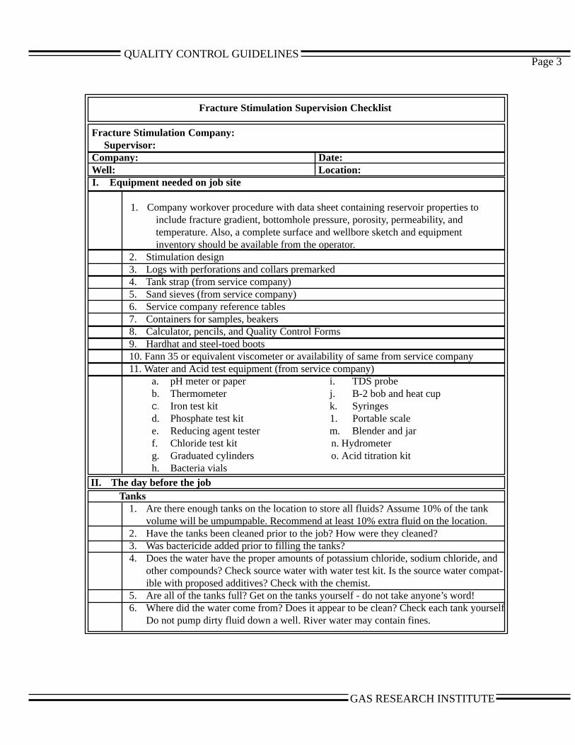
QUALITY CONTROL GUIDELINES
-
lf
Page 3
Fracture Stimulation Supervision Checklist
Fracture Stimulation Company:Supervisor:
Company: Date:Well: Location:
I. Equipment needed on job site
1. Company workover procedure with data sheet containing reservoir properties toinclude fracture gradient, bottomhole pressure, porosity, permeability, andtemperature. Also, a complete surface and wellbore sketch and equipmentinventory should be available from the operator.
2. Stimulation design3. Logs with perforations and collars premarked4. Tank strap (from service company)5. Sand sieves (from service company)6. Service company reference tables7. Containers for samples, beakers8. Calculator, pencils, and Quality Control Forms9. Hardhat and steel-toed boots10. Fann 35 or equivalent viscometer or availability of same from service company11. Water and Acid test equipment (from service company)
a. pH meter or paper i. TDS probeb. Thermometer j. B-2 bob and heat cupC. Iron test kit k. Syringesd. Phosphate test kit 1. Portable scalee. Reducing agent tester m. Blender and jarf. Chloride test kit n. Hydrometerg. Graduated cylinders o. Acid titration kith. Bacteria vials
II. The day before the jobTanks
1. Are there enough tanks on the location to store all fluids? Assume 10% of the tankvolume will be umpumpable. Recommend at least 10% extra fluid on the location.
2. Have the tanks been cleaned prior to the job? How were they cleaned?3. Was bactericide added prior to filling the tanks?4. Does the water have the proper amounts of potassium chloride, sodium chloride, and
other compounds? Check source water with water test kit. Is the source water compatible with proposed additives? Check with the chemist.
5. Are all of the tanks full? Get on the tanks yourself - do not take anyone’s word!6. Where did the water come from? Does it appear to be clean? Check each tank yourse
Do not pump dirty fluid down a well. River water may contain fines.
GAS RESEARCH INSTITUTE
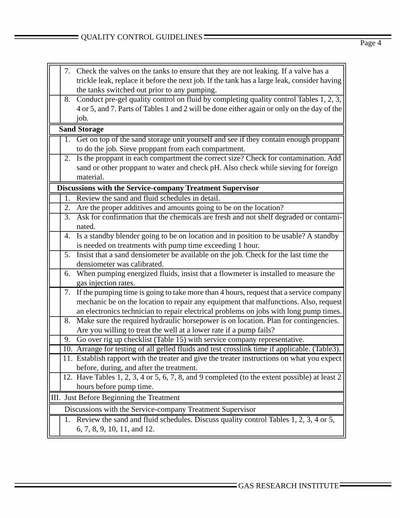
QUALITY CONTROL GUIDELINES
ng
,the
ant
dd
i-
by
nyests.s.
).ect
st 2
,
Page 4
7. Check the valves on the tanks to ensure that they are not leaking. If a valve has atrickle leak, replace it before the next job. If the tank has a large leak, consider havithe tanks switched out prior to any pumping.
8. Conduct pre-gel quality control on fluid by completing quality control Tables 1, 2, 34 or 5, and 7. Parts of Tables 1 and 2 will be done either again or only on the day of job.
Sand Storage1. Get on top of the sand storage unit yourself and see if they contain enough propp
to do the job. Sieve proppant from each compartment.2. Is the proppant in each compartment the correct size? Check for contamination. A
sand or other proppant to water and check pH. Also check while sieving for foreignmaterial.
Discussions with the Service-company Treatment Supervisor1. Review the sand and fluid schedules in detail.2. Are the proper additives and amounts going to be on the location?3. Ask for confirmation that the chemicals are fresh and not shelf degraded or contam
nated.4. Is a standby blender going to be on location and in position to be usable? A stand
is needed on treatments with pump time exceeding 1 hour.5. Insist that a sand densiometer be available on the job. Check for the last time the
densiometer was calibrated.6. When pumping energized fluids, insist that a flowmeter is installed to measure the
gas injection rates.7. If the pumping time is going to take more than 4 hours, request that a service compa
mechanic be on the location to repair any equipment that malfunctions. Also, requan electronics technician to repair electrical problems on jobs with long pump time
8. Make sure the required hydraulic horsepower is on location. Plan for contingencieAre you willing to treat the well at a lower rate if a pump fails?
9. Go over rig up checklist (Table 15) with service company representative. 10. Arrange for testing of all gelled fluids and test crosslink time if applicable. (Table3 11. Establish rapport with the treater and give the treater instructions on what you exp
before, during, and after the treatment. 12. Have Tables 1, 2, 3, 4 or 5, 6, 7, 8, and 9 completed (to the extent possible) at lea
hours before pump time.
III. Just Before Beginning the Treatment
Discussions with the Service-company Treatment Supervisor1. Review the sand and fluid schedules. Discuss quality control Tables 1, 2, 3, 4 or 5
6, 7, 8, 9, 10, 11, and 12.
GAS RESEARCH INSTITUTE

QUALITY CONTROL GUIDELINESQUALITY CONTROL GUIDELINESPage 5
2. Specify whether clean or dirty volumes will be recorded. Clean volumes are fluidvolumes with no sand. Dirty volumes are the slurry volumes. Also check to see ifthe volumes will be displayed in barrels or gallons.Dirty volume, bbl = Clean volume, bbl + (lb/gal sand x 0.00109)
= bbl + ( lb/gal x 0.00109)= bbl
orDirty volume, gal = Clean volume, gal + (lb sand x 0.0456)
= gal + ( lb x 0.0456)= gal
3. Calculate the foam quality that will be pumped (if applicable).
Quality - Nitrogen Rate, scf/min x Volume Factor, bbl/scf
Liquid Rate, bbl/min + Nitrogen Rate x Volume Factor
Calculate required sand addition at the blender, PPA
PPA, lb/gal - Desired Bottomhole Sand Concentration, lb/gal
(1-Quality)
Check with the treater to ensure the blender can handle the required PPA additional
rate!
PPA Addition Rate, lb/min PPA x Clean Rate, gal/min
Calculate Foam Volumes
Clean Volume, gal or bbl
Foam Volume, gal or bbl = (1-Quality)
4. Finalize the pumping schedule on Table 4 or 5.5. Get on top of the tanks YOURSELF and gauge ALL frac tanks using a tank strap.
HAVE THE TREATER PRESENT . Having the treater gauge the tanks with youwill prevent any disagreements about fluid volumes after the job is finished. Thisstep should be completed only after all tanks have been rolled and viscosified.
6. Set up a system with the treater for numbering the tanks in the order that theywill be drained. This helps keep track of the fluid volumes during the job.
7. Fill in the Frac Tank Tracking Chart (Table 8). This will help you keep track ofhow much fluid is left at any point during the job.
8. Arrange with the treater to have someone knowledgeable and dependable on top ofthe frac tanks. He or she should be there all the time that the job is being pumped toensure a smooth uninterrupted flow of the proposed pumping schedule.
9. Impress upon the treater the adverse consequences if the pumps lose prime duringthe job because the tanks were sucked too low. When the fluid level in the frac tankdrops below the suction valve, air is sucked into the pumps, causing the blenderpumps to lose prime. The sand concentration becomes extremely high, and the ratehas to be reduced. The sand concentration then tends to drop very low while thepumps regain prime. This chaos normally takes 5 to 10 min to correct -- 10 min isa lot of fluid at 50 bbl/min!
GAS RESEARCH INSTITUTEGAS RESEARCH INSTITUTE
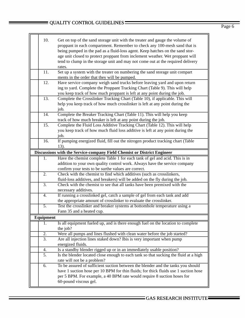
QUALITY CONTROL GUIDELINESQUALITY CONTROL GUIDELINESPage 6
10. Get on top of the sand storage unit with the treater and gauge the volume ofproppant in each compartment. Remember to check any 100-mesh sand that isbeing pumped in the pad as a fluid-loss agent. Keep hatches on the sand stor-age unit closed to protect proppant from inclement weather. Wet proppant willtend to clump in the storage unit and may not come out at the required deliveryrates.
11. Set up a system with the treater on numbering the sand storage unit compartments in the order that they will be pumped.
12. Have service company weigh sand trucks before leaving yard and upon returning to yard. Complete the Proppant Tracking Chart (Table 9). This will helpyou keep track of how much proppant is left at any point during the job.
13. Complete the Crosslinker Tracking Chart (Table 10), if applicable. This willhelp you keep track of how much crosslinker is left at any point during thejob.
14. Complete the Breaker Tracking Chart (Table 11). This will help you keeptrack of how much breaker is left at any point during the job.
15. Complete the Fluid Loss Additive Tracking Chart (Table 12). This will helpyou keep track of how much fluid loss additive is left at any point during thejob.
16. If pumping energized fluid, fill out the nitrogen product tracking chart (Table13).
Discussions with the Service-company Field Chemist or District Engineer1. Have the chemist complete Table 1 for each tank of gel and acid. This is in
addition to your own quality control work. Always have the service companyconfirm your tests to be surthe values are correct.
2. Check with the chemist to find which additives (such as crosslinkers,fluid-loss additives, and breakers) will be added on the fly during the job.
3. Check with the chemist to see that all tanks have been premixed with thenecessary additives.
4. If running a crosslinked gel, catch a sample of gel from each tank and addthe appropriate amount of crosslinker to evaluate the crosslinker.
5. Test the crosslinker and breaker systems at bottomhole temperature using aFann 35 and a heated cup.
Equipment1. Is all equipment fueled up, and is there enough fuel on the location to complete
the job?2. Were all pumps and lines flushed with clean water before the job started?3. Are all injection lines staked down? Ibis is very important when pump
energized fluids.4. Is a standby blender rigged up or in an immediately usable position?5. Is the blender located close enough to each tank so that sucking the fluid at a high
rate will not be a problem?6. To be assured of sufficient suction between the blender and the tanks you should
have 1 suction hose per 10 BPM for thin fluids; for thick fluids use 1 suction hoseper 5 BPM. For example, a 40 BPM rate would require 8 suction hoses for60-pound viscous gel.
GAS RESEARCH INSTITUTEGAS RESEARCH INSTITUTE
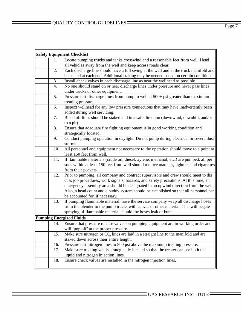
QUALITY CONTROL GUIDELINES
ndns.
es
en
r
st
t at
rttes
isnell.l can
s
nd
Page 7
Safety Equipment Checklist1. Locate pumping trucks and tanks crosswind and a reasonable feet from well. Head
all vehicles away from the well and keep access roads clear.2. Each discharge line should have a full swing at the well and at the truck manifold a
be staked at each end. Additional staking may be needed based on certain conditio3. Install check valves in each discharge line as near the wellhead as possible.4. No one should stand on or near discharge lines under pressure and never pass lin
under trucks or other equipment.5. Pressure test discharge lines from pump to well at 500± psi greater than maximum
treating pressure.6. Inspect wellhead for any low pressure connections that may have inadvertently be
added during well servicing.7. Bleed off lines should be staked and in a safe direction (downwind, downhill, and/o
to a pit).8. Ensure that adequate fire fighting equipment is in good working condition and
strategically located.9. Conduct pumping operation in daylight. Do not pump during electrical or severe du
storms.10. All personnel and equipment not necessary to the operation should move to a poin
least 150 feet from well.11. If flammable materials (crude oil, diesel, xylene, methanol, etc.) are pumped, all pe
sons within at least 150 feet from well should remove matches, lighters, and cigarefrom their pockets.
12. Prior to pumping, all company and contract supervisors and crew should meet to dcuss job procedures, work signals, hazards, and safety precautions. At this time, aemergency assembly area should be designated in an upwind direction from the wAlso, a head count and a buddy system should be established so that all personnebe accounted for, if necessary.
13. If pumping flammable material, have the service company wrap all discharge hosefrom the blender to the pump trucks with canvas or other material. This will negatespraying of flammable material should the hoses leak or burst.
Pumping Energized Fluids14. Ensure that pressure release valves on pumping equipment are in working order a
will ‘pop off’ at the proper pressure.15. Make sure nitrogen or C0
2 lines are laid in a straight line to the manifold and are
staked down across their entire length.16. Pressure test nitrogen lines to 500 psi above the maximum treating pressure.17. Make sure treating van is strategically located so that the treater can see both the
liquid and nitrogen injection lines.18. Ensure check valves are installed in the nitrogen injection lines.
GAS RESEARCH INSTITUTE
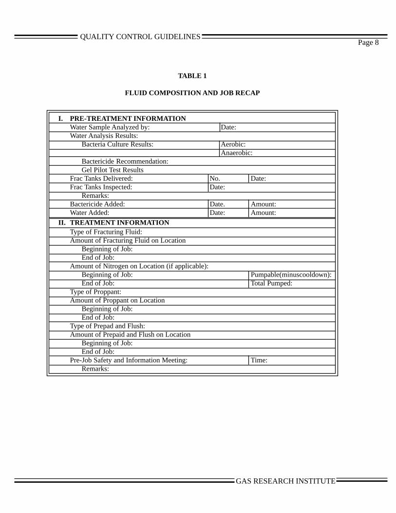
QUALITY CONTROL GUIDELINESPage 8
TABLE 1
FLUID COMPOSITION AND JOB RECAP
I. PRE-TREATMENT INFORMATIONWater Sample Analyzed by: Date:Water Analysis Results:
Bacteria Culture Results: Aerobic:Anaerobic:
Bactericide Recommendation:Gel Pilot Test Results
Frac Tanks Delivered: No. Date:Frac Tanks Inspected: Date:
Remarks:Bactericide Added: Date. Amount:Water Added: Date: Amount:
II. TREATMENT INFORMATIONType of Fracturing Fluid:Amount of Fracturing Fluid on Location
Beginning of Job:End of Job:
Amount of Nitrogen on Location (if applicable):Beginning of Job: Pumpable(minuscooldown):End of Job: Total Pumped:
Type of Proppant:Amount of Proppant on Location
Beginning of Job:End of Job:
Type of Prepad and Flush:Amount of Prepaid and Flush on Location
Beginning of Job:End of Job:
Pre-Job Safety and Information Meeting: Time:Remarks:
GAS RESEARCH INSTITUTE
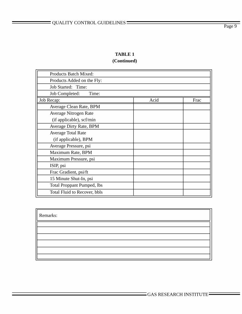
QUALITY CONTROL GUIDELINESPage 9
TABLE 1(Continued)
Products Batch Mixed:Products Added on the Fly:Job Started: Time:Job Completed: Time:
Job Recap: Acid FracAverage Clean Rate, BPMAverage Nitrogen Rate (if applicable), scf/minAverage Dirty Rate, BPMAverage Total Rate (if applicable), BPMAverage Pressure, psiMaximum Rate, BPMMaximum Pressure, psiISIP, psiFrac Gradient, psi/ft15 Minute Shut-In, psiTotal Proppant Pumped, lbs
Total Fluid to Recover, bbls
Remarks:
GAS RESEARCH INSTITUTE
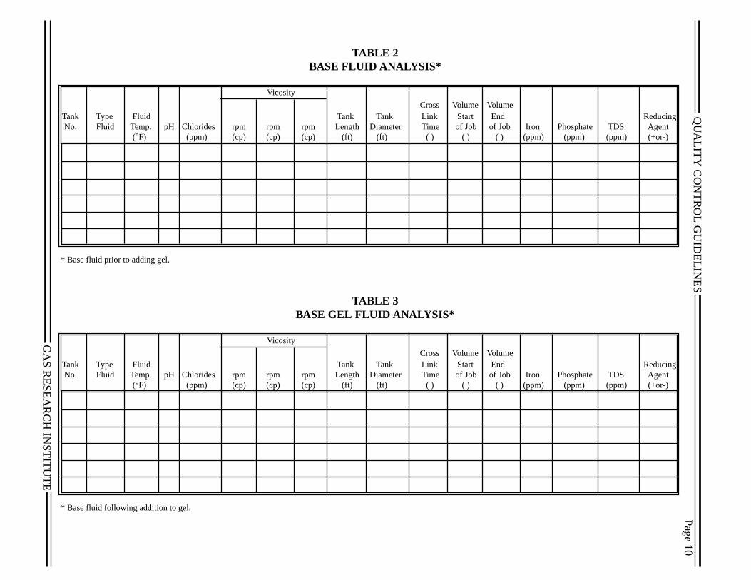
QU
ALIT
Y C
ON
TR
OL G
UID
ELIN
ES
GA
S R
ES
EA
RC
H IN
ST
ITU
TE
TABLE 2BASE FLUID ANALYSIS*
Vicosity
Cross Volume VolumeTank Type Fluid Tank Tank Link Start End Reducing No. Fluid Temp. pH Chlorides rpm rpm rpm Length Diameter Time of Job of Job Iron Phosphate TDS Agent
(°F) (ppm) (cp) (cp) (cp) (ft) (ft) ( ) ( ) ( ) (ppm) (ppm) (ppm) (+or-)
* Base fluid prior to adding gel.
TABLE 3BASE GEL FLUID ANALYSIS*
Vicosity
Cross Volume VolumeTank Type Fluid Tank Tank Link Start End Reducing No. Fluid Temp. pH Chlorides rpm rpm rpm Length Diameter Time of Job of Job Iron Phosphate TDS Agent
(°F) (ppm) (cp) (cp) (cp) (ft) (ft) ( ) ( ) ( ) (ppm) (ppm) (ppm) (+or-)
* Base fluid following addition to gel.
Pag
e 10
QU
ALIT
Y C
ON
TR
OL G
UID
ELIN
ES
GA
S R
ES
EA
RC
H IN
ST
ITU
TE
Pa
TABLE 4PROPOSED GELLED FLUID PUMPING SCHEDULE*
During Treatment Checks Clean Dirty Proppant
Type Stage Stage Proppant Stage Proppant Cross Fluid SandStage Fluid Volume Volume Concentration Weight Remaining Linked Volumes Volumes
( ) ( ) (ppg) (lbs) (lbs) ( ) ( )
*Use this schedule for gelled fluid fracture treatments
ge 11

QU
ALIT
Y C
ON
TR
OL G
UID
ELIN
ES
GA
S R
ES
EA
RC
H IN
ST
ITU
TE
s
P
TABLE 5PROPOSED FOAM PUMPING SCHEDULE*
During Treatment Checks Clean Dirty Proppant
Type Stage Stage Proppant Stage Proppant Cross Fluid SandStage Fluid Volume Volume Concentration Weight Remaining Linked Volumes Volume
( ) ( ) (ppg) (lbs) (lbs) ( ) ( )
*Use this schedule for foam fracture treatments
age 12

QU
ALIT
Y C
ON
TR
OL G
UID
ELIN
ES
GA
S R
ES
EA
RC
H IN
ST
ITU
TE
rcent On
TABLE 12TABLE 12
DESCRIPTION OF FRACTURE PROPPANTS
Compartment No. Proppant Type
Sieve Sizes Percent On Percent On Percent On Percent On Percent On Percent On Percent On Percent On Percent On Pe
8
10
12
16
20
25
30
35
40
60
80
100
120
140
Pan
*If this data not available on location, have service company supply recent sieve analysis on sand in yard.
Page 13

QUALITY CONTROL GUIDELINESPage 14
TABLE 7DESCRIPTION OF FRACTURE FLUIDS
Fluid Type:Base Fluid:Salts Added: Type Amount /1000 galBase Gel: Type Amount /1000 galCrosslinker: Type Amount /1000 galBactericide: Type Amount /1000 galSurfactant: Type Amount /1000 galBuffer: Type Amount /1000 galBreaker: Type Amount /1000 galFluid Loss: Type Amount /1000 gal
Type Amount /1000 galType Amount /1000 gal
GAS RESEARCH INSTITUTE

QUALITY CONTROL GUIDELINESPage 15
TABLE 8FRAC TANK TRACKING CHART
GaugedVolume PumpableVolume* Volume onTank No. in Tank in Tank LocationAfter Treatment
( ) ( ) ( )
Total
*Pumpable volume = gauged volume - 10% of tank volume. (Some tank configurations may allowmore or less fluid removal. Consult with the treater as to pumpable tank volume.)
GAS RESEARCH INSTITUTE
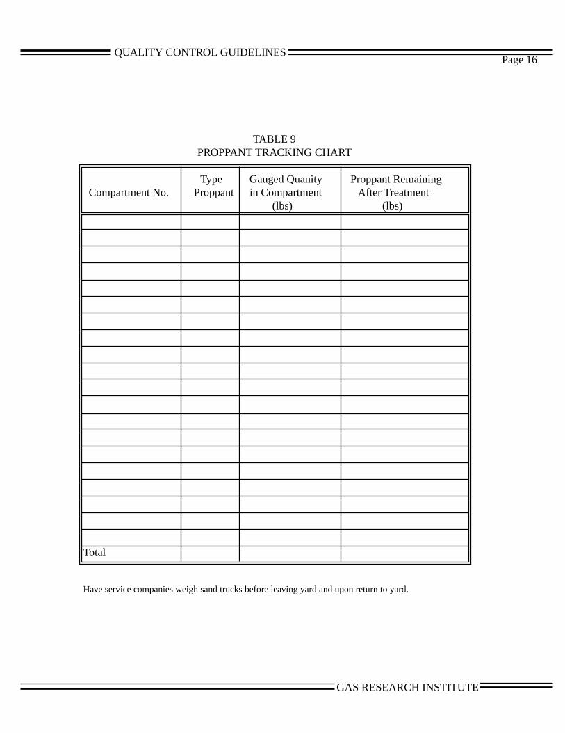
QUALITY CONTROL GUIDELINESPage 16
TABLE 9PROPPANT TRACKING CHART
Type Gauged Quanity Proppant Remaining Compartment No. Proppant in Compartment After Treatment
(lbs) (lbs)
Total
Have service companies weigh sand trucks before leaving yard and upon return to yard.
GAS RESEARCH INSTITUTE
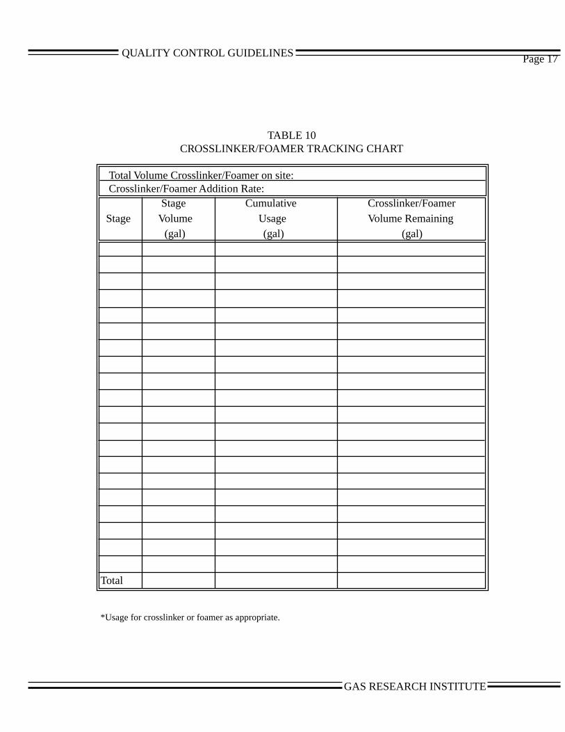
QUALITY CONTROL GUIDELINES Page 17
TABLE 10CROSSLINKER/FOAMER TRACKING CHART
Total Volume Crosslinker/Foamer on site:Crosslinker/Foamer Addition Rate:
Stage Cumulative Crosslinker/Foamer Stage Volume Usage Volume Remaining
(gal) (gal) (gal)
Total
*Usage for crosslinker or foamer as appropriate.
GAS RESEARCH INSTITUTE
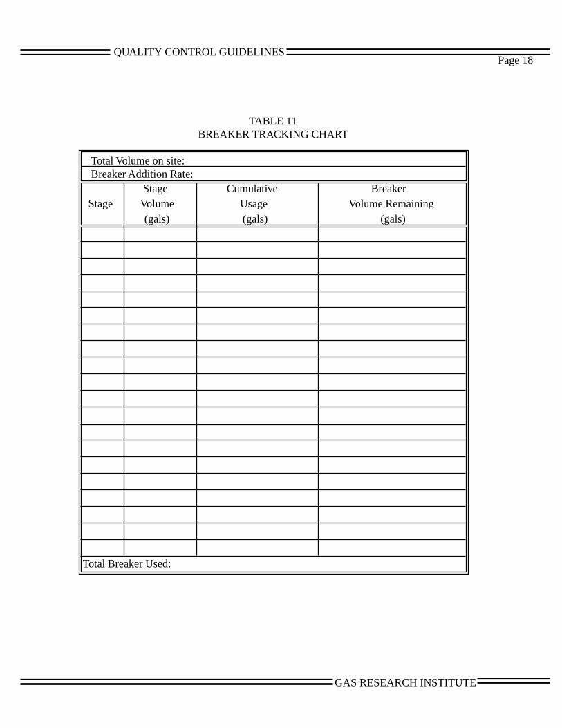
QUALITY CONTROL GUIDELINESPage 18
TABLE 11BREAKER TRACKING CHART
Total Volume on site:Breaker Addition Rate:
Stage Cumulative Breaker Stage Volume Usage Volume Remaining
(gals) (gals) (gals)
Total Breaker Used:
GAS RESEARCH INSTITUTE
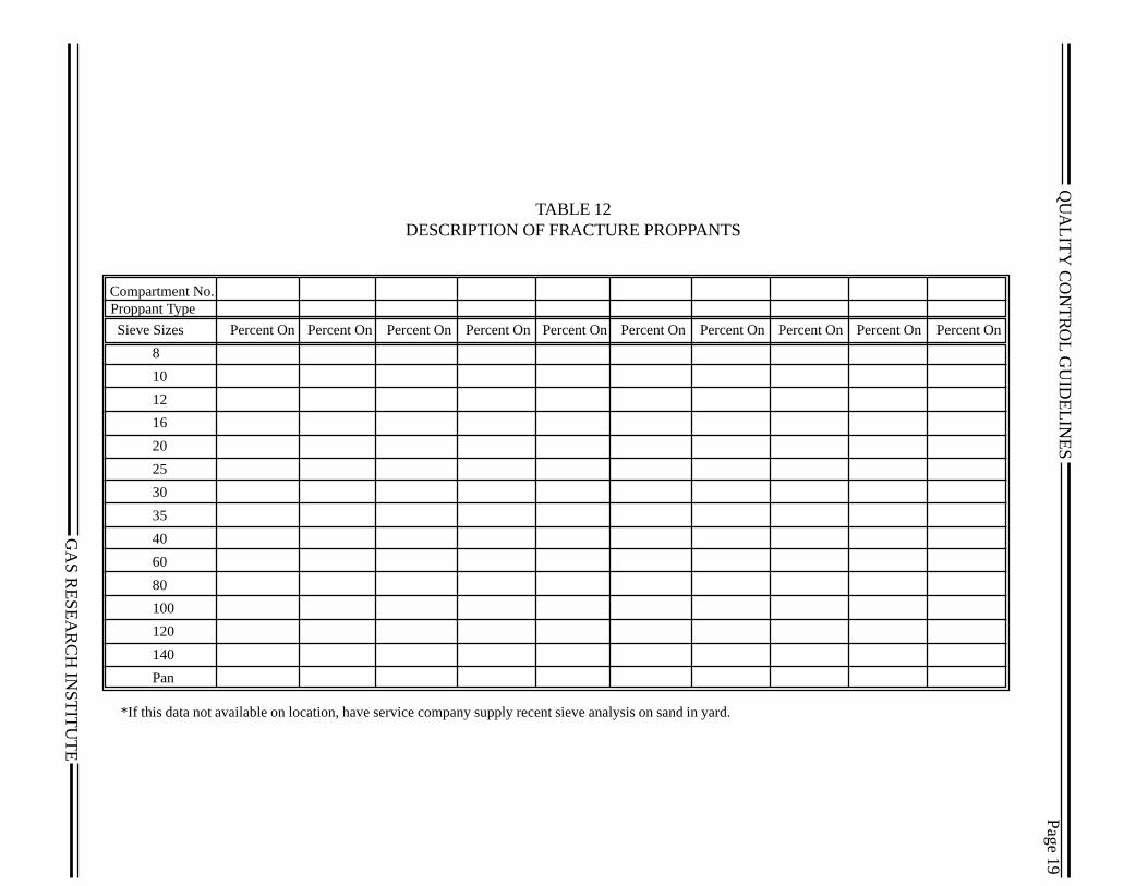
QU
ALIT
Y C
ON
TR
OL G
UID
ELIN
ES
TABLE 12
cent On
GA
S R
ES
EA
RC
H IN
ST
ITU
T
TABLE 12DESCRIPTION OF FRACTURE PROPPANTS
Compartment No. Proppant Type
Sieve Sizes Percent On Percent On Percent On Percent On Percent On Percent On Percent On Percent On Percent On Per
8
10
12
16
20
25
30
35
40
60
80
100
120
140
Pan
*If this data not available on location, have service company supply recent sieve analysis on sand in yard.
E
Page 19

QU
ALIT
Y C
ON
TR
OL G
UID
ELIN
ES
GA
S R
ES
EA
RC
H IN
ST
ITU
TABLE 13NITROGEN PRODUCTION TRACKING CHART
Truck 1 Truck 2 Truck 3 Truck 4 Truck 5 Total Planned % Remaining % Remaining % Remaining % Remaining % Remaining Volume
Stage Usage Remaining1 Volume2 Remaining Volume Remaining Volume Remaining Volume Remaining Volume Used (scf) (scf) (scf) (scf) (scf) (scf) (scf)
1Read from guage on service company nitrogen truck.2Obtain volimes from service company charts for the nitrogen truck.
TE
Page 20
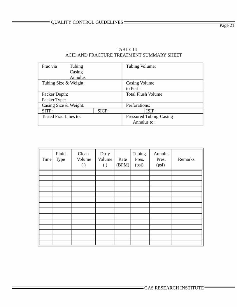
QUALITY CONTROL GUIDELINESPage 21
TABLE 14ACID AND FRACTURE TREATMENT SUMMARY SHEET
Frac via Tubing Tubing Volume:CasingAnnulus
Tubing Size & Weight: Casing Volumeto Perfs:
Packer Depth: Total Flush Volume:Packer Type:Casing Size & Weight: Perforations:SITP: SICP: ISIP:Tested Frac Lines to: Pressured Tubing-Casing
Annulus to:
Fluid Clean Dirty Tubing AnnulusTime Type Volume Volume Rate Pres. Pres. Remarks
( ) ( ) (BPM) (psi) (psi)
GAS RESEARCH INSTITUTE
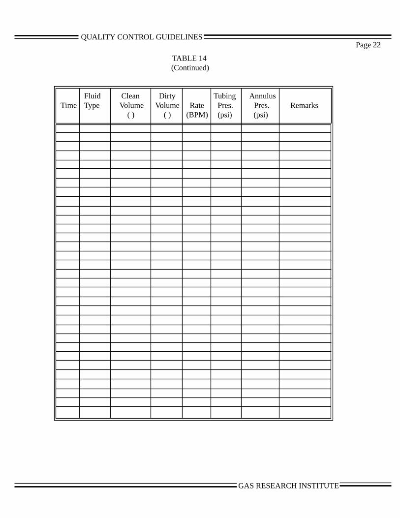
QUALITY CONTROL GUIDELINES 22
TABLE 14(Continued)
Fluid Clean Dirty Tubing AnnulusTime Type Volume Volume Rate Pres. Pres. Remarks
( ) ( ) (BPM) (psi) (psi)
Page
GAS RESEARCH INSTITUTE

QUALITY CONTROL GUIDELINESPage 23
ele
n
d
asheeryps
r.
tty.rs
off
TABLE 15 RIG UP CHECKLIST
1. Compact rig-up - minimum iron usedThis is a judgment call that will come with experience. What we are looking for here is utilization ofthe smallest amount of flexible iron possible. We have seen many times, simply because of personnlacking expertise or insome occasions ignorance or laziness, a large amount of iron is placed on thlocation. In addition to being dangerous and just more material which may leak or fail, excessive irocan cause high treating pressures and inefficient use of hydraulic horsepower. A compact locationwhere very little iron is used from the trucks to a manifold and then a single large line to the wellheaat a relatively safe distance is your goal. Trucks parked helter skelter around location and little caretaken in positioning the trucks for maximum efficiency should be discussed with the service com-pany.
2. Safe practical distance from the wellhead.Some years ago, major oil companies specified 100 or 200 ft from the wellhead for all their treatments. We are all aware that in many cases, particularly mountainous terrain, this simply is not possible. We believe that efforts should be made to remove fuel tanks, engines and other devices as farpossible from the wellhead should a fire or leak occur. You need to use common sense protecting twellhead and equipment in the event of a disaster. There are some locations where you must be vclose to the wellhead to get the equipment on location. In this case, we recommend having the pumand fluid ends located in the proximity of the wellhead, and the drive engines, blenders, and otherassorted equipment as far away as possible.
3. Treating iron large enough to accommodate anticipated treating rate.Typical sizes of treating iron available from service companies are 2-inch, 3-inch, and 4-inch. A goodworking rule of thumb for a 2-inch iron is 8 bbls/min maximum rate; 3-inch, 20 bbls/min; and 4-inch,37 bbls/min. A major consideration is that above these rates excessive friction pressures may occuAlso, when using proppants, you would expect a much shorter life on the iron in relation to pumpingabrasive fluids, i.e., proppants. It should be noted that this rate or the total rate that we are talkingabout is from the final manifold that comes together from all of the trucks going to the wellhead.Obviously, each of the individual trucks does not have to have 4-inch iron if you are going to bepumping at 30 bbls/min. Typically, you may have 2- or 3-inch iron coming from the individual truckswhose rate may not exceed 8 to 10 bbls/min.
4. A check valve properly installed near the wellhead.The most common mistake in the use of check valves is placing them at great distances from thewellhead. The check valve is the last resort should your iron part between the check valve and thetreating equipment. This no flow/return flow valve should be as close as possible to the injection poingoing into the well. Many times the vibration that typically occurs on a fracture treatments occurs aor near the wellhead. If one parts the pipe downstream of the check valve, then it has no functionalitYou need to question the personnel to be sure they are using a flapper type check valve if ball sealeor large materials are going to be used compared to a dart type check valve which can be plugged with ball sealers or diverting agents. Flapper type check valves need to be positioned so that theflapper will close in event of no positive flow through the pipe.
GAS RESEARCH INSTITUTE
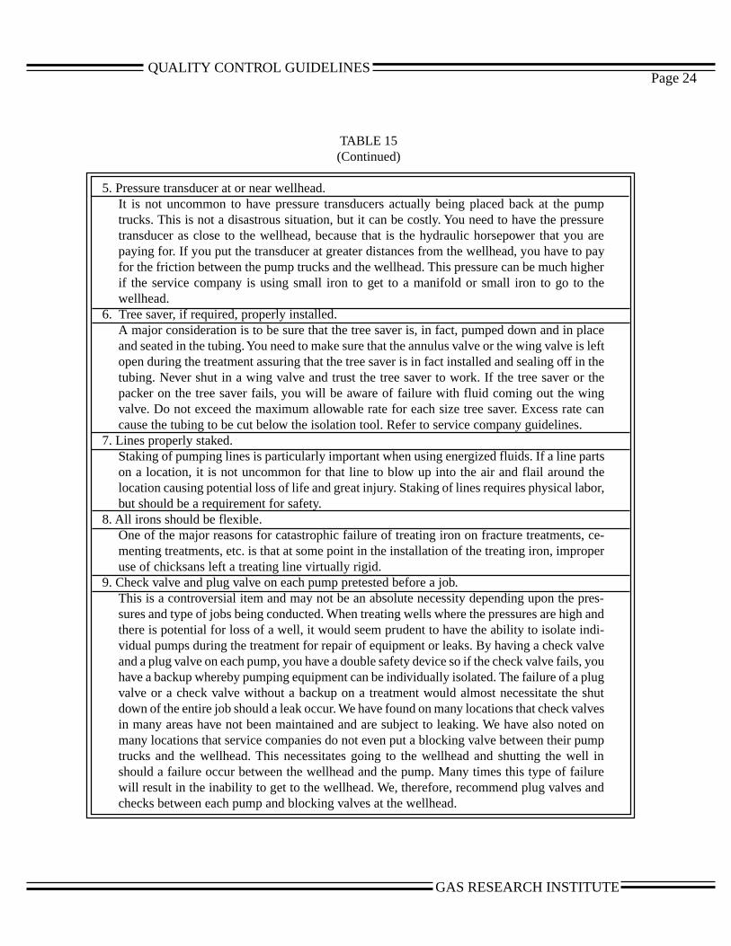
QUALITY CONTROL GUIDELINESPage 24
TABLE 15(Continued)
5. Pressure transducer at or near wellhead.It is not uncommon to have pressure transducers actually being placed back at the pumptrucks. This is not a disastrous situation, but it can be costly. You need to have the pressuretransducer as close to the wellhead, because that is the hydraulic horsepower that you arepaying for. If you put the transducer at greater distances from the wellhead, you have to payfor the friction between the pump trucks and the wellhead. This pressure can be much higherif the service company is using small iron to get to a manifold or small iron to go to thewellhead.
6. Tree saver, if required, properly installed.A major consideration is to be sure that the tree saver is, in fact, pumped down and in placeand seated in the tubing. You need to make sure that the annulus valve or the wing valve is leftopen during the treatment assuring that the tree saver is in fact installed and sealing off in thetubing. Never shut in a wing valve and trust the tree saver to work. If the tree saver or thepacker on the tree saver fails, you will be aware of failure with fluid coming out the wingvalve. Do not exceed the maximum allowable rate for each size tree saver. Excess rate cancause the tubing to be cut below the isolation tool. Refer to service company guidelines.
7. Lines properly staked.Staking of pumping lines is particularly important when using energized fluids. If a line partson a location, it is not uncommon for that line to blow up into the air and flail around thelocation causing potential loss of life and great injury. Staking of lines requires physical labor,but should be a requirement for safety.
8. All irons should be flexible.One of the major reasons for catastrophic failure of treating iron on fracture treatments, ce-menting treatments, etc. is that at some point in the installation of the treating iron, improperuse of chicksans left a treating line virtually rigid.
9. Check valve and plug valve on each pump pretested before a job.This is a controversial item and may not be an absolute necessity depending upon the pres-sures and type of jobs being conducted. When treating wells where the pressures are high andthere is potential for loss of a well, it would seem prudent to have the ability to isolate indi-vidual pumps during the treatment for repair of equipment or leaks. By having a check valveand a plug valve on each pump, you have a double safety device so if the check valve fails, youhave a backup whereby pumping equipment can be individually isolated. The failure of a plugvalve or a check valve without a backup on a treatment would almost necessitate the shutdown of the entire job should a leak occur. We have found on many locations that check valvesin many areas have not been maintained and are subject to leaking. We have also noted onmany locations that service companies do not even put a blocking valve between their pumptrucks and the wellhead. This necessitates going to the wellhead and shutting the well inshould a failure occur between the wellhead and the pump. Many times this type of failurewill result in the inability to get to the wellhead. We, therefore, recommend plug valves andchecks between each pump and blocking valves at the wellhead.
GAS RESEARCH INSTITUTE
QUALITY CONTROL GUIDELINES
en-
st
in
s,
Page 25
TABLE 15(Continued)
10. Check minimum and maximum rates for trailer manifold, if used.It happens many times that pigs, manifold trailers, ground manifolds, or other terminology usedfor this type of equipment are designed for a maximum rate or in many cases for a minimum rate.Ile same restrictions apply on maximum rate through the manifold trailer as far as discharge lines.If you are going to have to pump 40 or 50 bbl/min and you have a 3-inch I.D. discharge line in themanifold trailer or the manifold itself, severe corrosion or friction will occur in the manifold.Additionally, these trailer manifolds or ground manifolds have large I.D. suctions. This can causea great deal of proppant settling and potential plugging off on low viscosity delayed crosslink jobsor foam frac treatments where high proppant concentrations are being pumped. Discuss the pottial settling out of high concentrations of proppant in low viscosity fluids with the service com-pany if trailer manifolds are going to be used where these conditions exist.
11. Check for sufficient suction hose and evaluate velocity per hose.It is very common to find insufficient suction hose being used between the frac tanks and theblender and additionally insufficient hose being used on the discharge side of the blender. A goodrule of thumb for 10 to 20 ft sections of 4-inch hose on the backside of the blender is that you muhave one hose per 10 bbl/min of suction required for thin fluid, i.e., prepad or flush fluid. Youshould have one 4-inch hose for 5 bbl/min if pumping a 50 or 60 lb viscous gel. In the case of thedischarge side where you are using pressurizing pumps, you need at least one hose for 10 bbl/mof discharge rate. Obviously, you need to consider the length of hosing and add additional hoses ifthere are indications of pumps starving, i.e., not getting fluid. This becomes a very importantconsideration on large treatments where many trucks are positioned at fairly large distances fromthe pressurizing blender.
There is another consideration that needs to be taken into account when using high concentrationsof proppant, as in foam fracturing treatments. Here, you need to maintain high velocities per hoseto keep settling out and slugging of proppants occurring in low viscosity fluids. Where pumpingvery high concentrations of proppants such as 18 to 21 lb/gal from the blender to the pump truckyou need to keep the hose length as short as possible and use as small an I.D. hose as will achievethe necessary rate without starving the pump.
12. Check horsepower and plunger sizes of pumps on location.This would appear to be something that is obvious and not the responsibility of the quality controlengineer. That simply is not the case. You need to question the service engineer and find out theplunger size and horsepower of all trucks on location. By doing so and having him give you a flowrate versus pressure at various gear rates for the pumps, you have a backup for flow should flowmetersor other devices fail during the treatment. Additionally, it is not uncommon to have equipment onlocation that is not suited for the pumping pressures anticipated on the treatment. This would occurif large size plungers were on location where very high pressure pumping would occur. Humanbeings are used to set up equipment, and people make mistakes. The use of equipment not de-signed for high pressure pumping or alternatively high rate pumping where small size plungers areon pumps on location can cause very rapid failure of this equipment
GAS RESEARCH INSTITUTE
QUALITY CONTROL GUIDELINES
r.
Page 26
TABLE 15(Continued)
13. Check flow monitoring equipment before the job.It is always advisable to circulate the equipment on location and be sure that flowmeters,densiometers, etc. are functioning prior to starting the treatment. This should be done the daybefore or early in the morning of the treatment so that any electronic problems can be worked outand not delay treatments. Ensure that the flowmeters are properly sized for the designed pumprates. This is especially important on foam treatments, because liquid pump rates are typicallymuch lower than on normal non-foam treatments. Know the minimum flow rate the meters canmeasure accurately. This applies to all types of meters (turbine, venturi, mass, etc.).
14. Estimate available fluid removable from the tanks.Depending upon the type of frac tanks used, there is always a certain portion that is simply notpractically removed from that tank during that treatment. With large lay down 500 bbl tanks, it isnot uncommon that you will leave 50 bbls or so of fluid in the tank. Attempting to suck lower thanthis on small volume or high rate treatments can cause loss of suction resulting in catastrophicproblems at the blender. Work with the service company along these lines making sure that youhave sufficient fluid to do the fracture treatment. Another approach would be to use work tanks tosupply fluid to the primary fracturing blender. The work tanks are kept full, providing good hydro-static pressure, by pumping from the other tanks into the work tank using a centrifugal pump oranother blender. This will allow you to draw the fluid level in the other tanks as low as possiblewithout the potential for losing suction at the primary blender. On large fracture treatments it isnot uncommon to use two or three work tanks. It is never a good practice to suck out of 8 or 10tanks simultaneously on a treatment. This allows no visual monitoring of pump rate during atreatment. You can very easily suck one of the tanks all the way down and lose prime, potentiallyscreening out the well.
15. Check placement of proppant storage to assure convenient movement and access to standby blendeIt obviously does no good to have standby blenders if you cannot get proppant to that blenderduring the treatment. A standby blender should be one that can immediately come on if you losethe primary equipment. The standby blender should be primed up and running before and duringthe treatment. It is also good practice to ask the service company to bring on the standby blenderduring the prepad of the treatment to see its efficiency in doing so, and then go back to the primaryequipment. You need to physically look and be sure that proppant can get to the blender. Oneneeds to check suction hoses and discharge hoses and be sure they are properly rigged up andchemical can be transferred and added when using a standby blender.
16. Double check working pressure rating on frac iron.We recommend physically walking around looking at the iron, and questioning the people onlocation if something does not look right. You should ask the personnel if all the iron is, in fact, thesame pressure rating. A common problem here are fittings or connections at the wellhead that mayor may not be supplied by the service company. Examples of disastrous occurrences are using lowpressure L’s or T’s as crossover to the service company equipment. Double checking this equip-ment is an absolute must for safety and prevention of potential catastrophic accidents.
GAS RESEARCH INSTITUTE
QUALITY CONTROL GUIDELINES
Appendix CProcedures and Surface Equipment
forImplementing the Forced Closure Fracturing Technique
(Excerpt from “New Techniques and Quality ControlFind Success in Enhancing Productivity and
Minimizing Proppant Flowback”Ely, Arnold, and Holditch, 1990, SPE 20708)
GAS RESEARCH INSTITUTE

FORCED CLOSURE IMPLEMENTATION PROCEDURE
1. Be sure that the wellhead and flowback manifold system are installed and tested sothe well can be flowed back within 30 seconds of completing flush. Figure 12illustrates a typical surface layout for forced closure implementation.
2. If a liquid fracturing fluid is used, install a flow meter capable of monitoring ratesfrom 10to 20 gallons per minute downstream of a variable choke. If a foam frac-turing fluid is used, no flow meter is needed. The flowback rate of gas can becalculated from the pressure drop across the orifice.
3. Isolate the choke and flowmeter with a block valve during the treatment-
4. Insure that the choke is fully closed and isolated prior to starting the fracture treatment.
5. Within 30 seconds after completing the flush, open the block valve with the chokestill closed. If the choke fails, the block valve can be used as a back-up to regulateflow rate.
6. Open the choke slowly. Do not exceed a flowback rate of 10-15 gallons per minutefor liquids or an equivalent rate for gases.
7. Monitor pressure vs time to detect fracture closure.
8. Continue to flow at a low rate for 30 minutes after near wellbore fracture closurehas been detected.
9. The flowback rate can then be increased to 20-25 gallons per minute for liquids orequivalent rates for gases.
10. Continue flowing for an additional ’30 minutes. For normal pressured or energizedproduced fluids to measure sand content.wells, the flowback rate ran eventually beincreased to 1-2 BPM. Always monitor the produced fluids to measure sandcontent.
11.Choke back the well as necessary when gas or oil flow rates become large.
12.Flow the well for several days or weeks using choke sizes no larger than 10-12/64inch.
13.Monitor and record all data concerning flowing pressures and oil, gas and water flow rates.
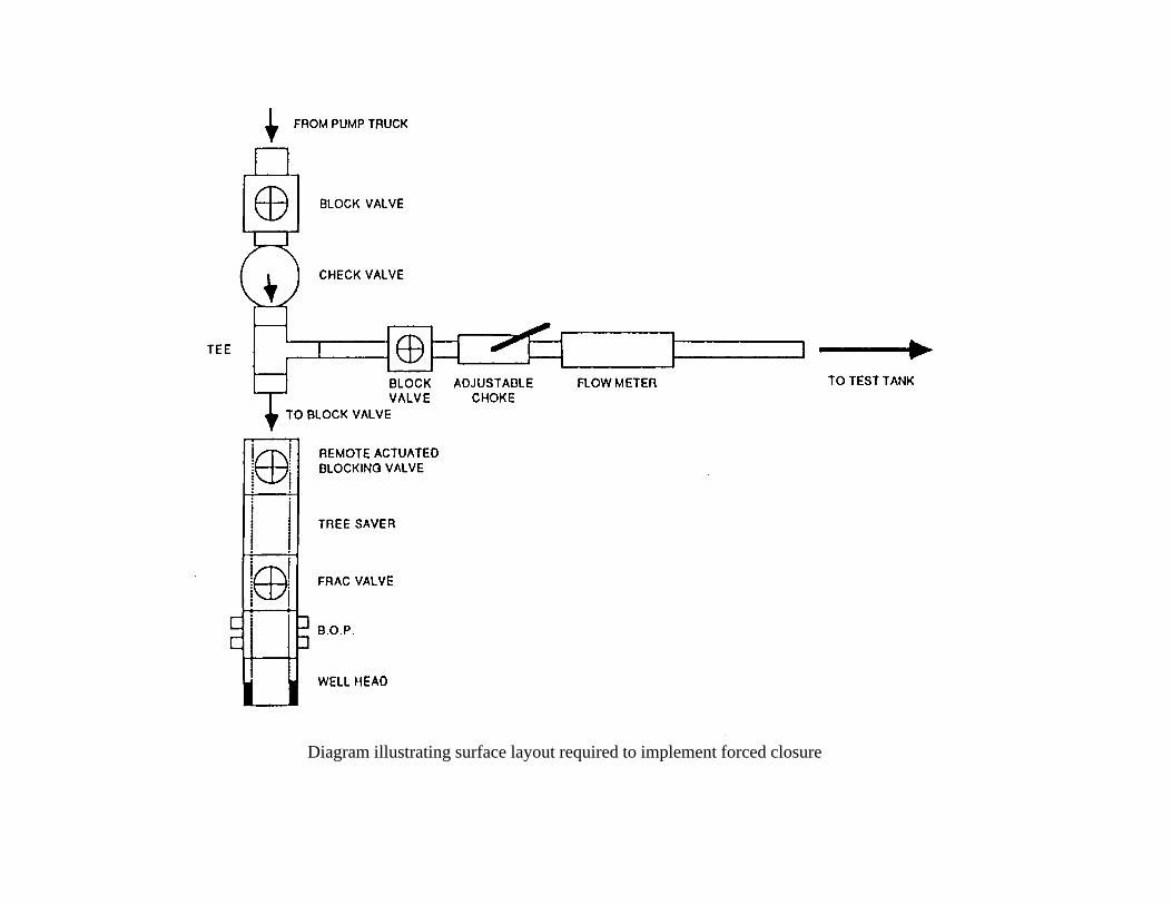
Diagram illustrating surface layout required to implement forced closure