Embed Size (px)
Citation preview
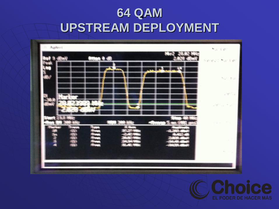
64 QAM
UPSTREAM
DEPLOYMENT
64 QAM UPSTREAM DEPLOYMENT
Why 64-QAM?
Higher upstream data throughput required for:
Voice, growing SMB’s using DOCSIS , Gamers, Peer to Peer.
Up to 120 Mbs for 4 bonded channels for DOCSIS 3 in the upstream.
Competition.
Business Services
Upstream 64-QAM: What Does it Take?
Cable 101 practices
A comprehensive and effective preventive maintenance
program
Aggressive leakage and ingress control
Tracking down high-transmit level modems
Manageable node sizes
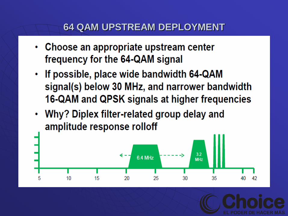
Placing of 64-QAM carrier signal between 20 and 30 MHz
center frequency
64 QAM UPSTREAM DEPLOYMENT
Upstream 64 QAM Challenges
Once interference occurs in voice the data cannot be
retransmitted.
Measurements are more difficult because the signals are bursty.
64 QAM looses 3 dB of headroom because the maximum modem output is 52 dBmV as opposed to 58 dBmV for QPSK
64 QAM UPSTREAM DEPLOYMENT
More Upstream Challenges with 64 QAM
64 QAM is less robust than 16 QAM
Requires better BER and MER
QAM means that the carrier is amplitude modulated and therefore more susceptible to amplitude based impairments such as:
Ingress
Micro-reflections
Compression
64 QAM UPSTREAM DEPLOYMENT
More Upstream Challenges with 64 QAM
One question that comes up is whether or not return
path Fabry Perot (FP) lasers will work with 64-QAM.
The short answer is yes, but a little “it depends” is
applicable here.
• In particular, can upstream optical links support the
additional channel loading of multiple bonded channels?
64 QAM UPSTREAM DEPLOYMENT
More Upstream Challenges with 64 QAM
Properly set up FP links will support one or two
64-QAM channels in the real world, but more than that really requires DFB or digital return links.
FP lasers simply don’t have the bit error rate (BER)
dynamic range to handle a bunch of channels.
Pay particular attention to upstream fiber link
alignment—this is critical, and can significantly
affect CNR and MER (“upstream SNR”)
64 QAM UPSTREAM DEPLOYMENT
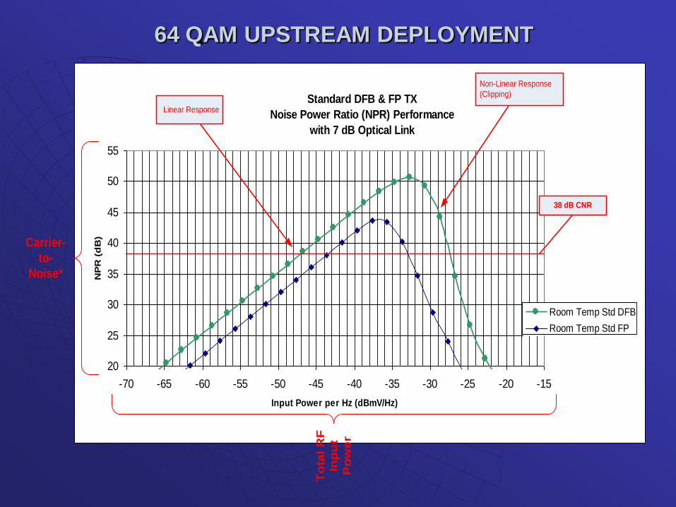
Standard DFB & FP TX
Noise Power Ratio (NPR) Performance
with 7 dB Optical Link
20
25
30
35
40
45
50
55
-70 -65 -60 -55 -50 -45 -40 -35 -30 -25 -20 -15
Input Power per Hz (dBmV/Hz)
NP
R (
dB
)
Room Temp Std DFB
Room Temp Std FP
Carrier-
to-
Noise*
To
tal R
F
Inp
ut
Po
we
r
38 dB CNR
Linear Response
Non-Linear Response
(Clipping)
64 QAM UPSTREAM DEPLOYMENT
64 QAM UPSTREAM DEPLOYMENT
Transit time and velocity of propagation
A signal takes a certain amount of time to pass through a filter
• The transit time through the filter is a function of the filter’s velocity of propagation (also called velocity factor)
• Velocity of propagation is the speed that an electromagnetic signal travels through some medium, usually expressed as a percentage of the speed of light in a vacuum
64 QAM UPSTREAM DEPLOYMENT
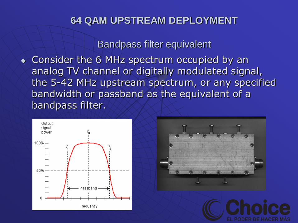
Bandpass filter equivalent
64 QAM UPSTREAM DEPLOYMENT
Bandpass filter equivalent
Consider the 6 MHz spectrum occupied by an
analog TV channel or digitally modulated signal, the 5-42 MHz upstream spectrum, or any specified bandwidth or passband as the equivalent of a bandpass filter.
64 QAM UPSTREAM DEPLOYMENT
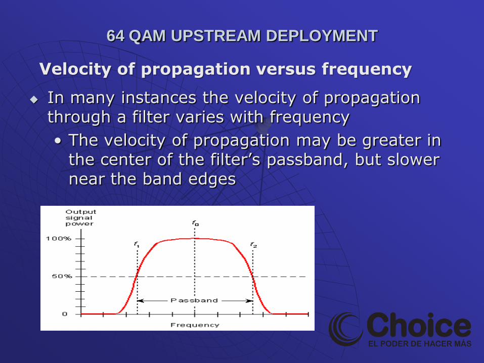
In many instances the velocity of propagation through a filter varies with frequency
• The velocity of propagation may be greater in the center of the filter’s passband, but slower near the band edges
Velocity of propagation versus frequency
The time required for a signal to pass through a filter—or any device for that matter—is called delay
• Absolute delay is the delay a signal experiences passing through the device at some reference frequency
64 QAM UPSTREAM DEPLOYMENT
64 QAM
UPSTREAM DEPLOYMENT
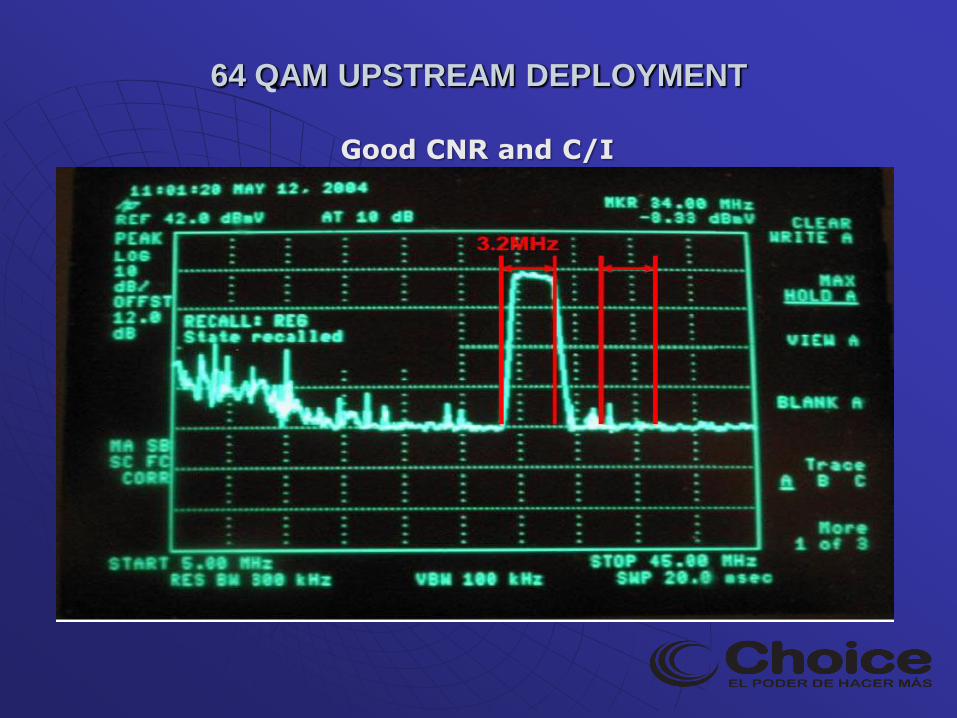
Good CNR and C/I
64 QAM UPSTREAM DEPLOYMENT
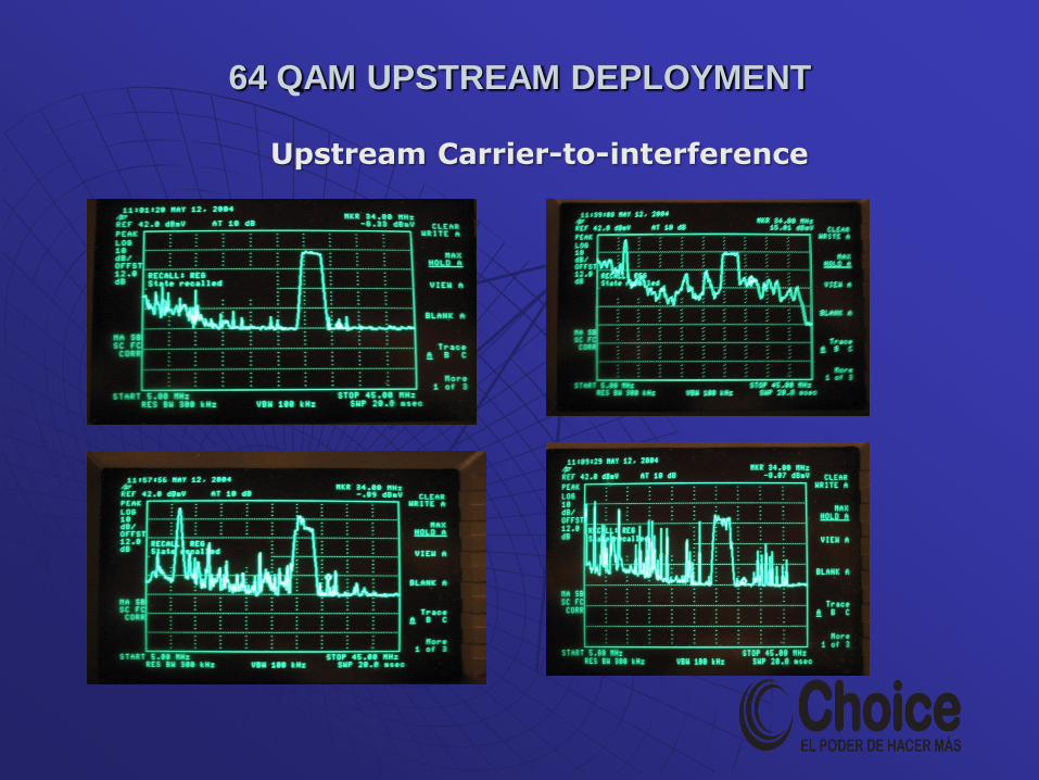
Upstream Carrier-to-interference
64 QAM UPSTREAM DEPLOYMENT
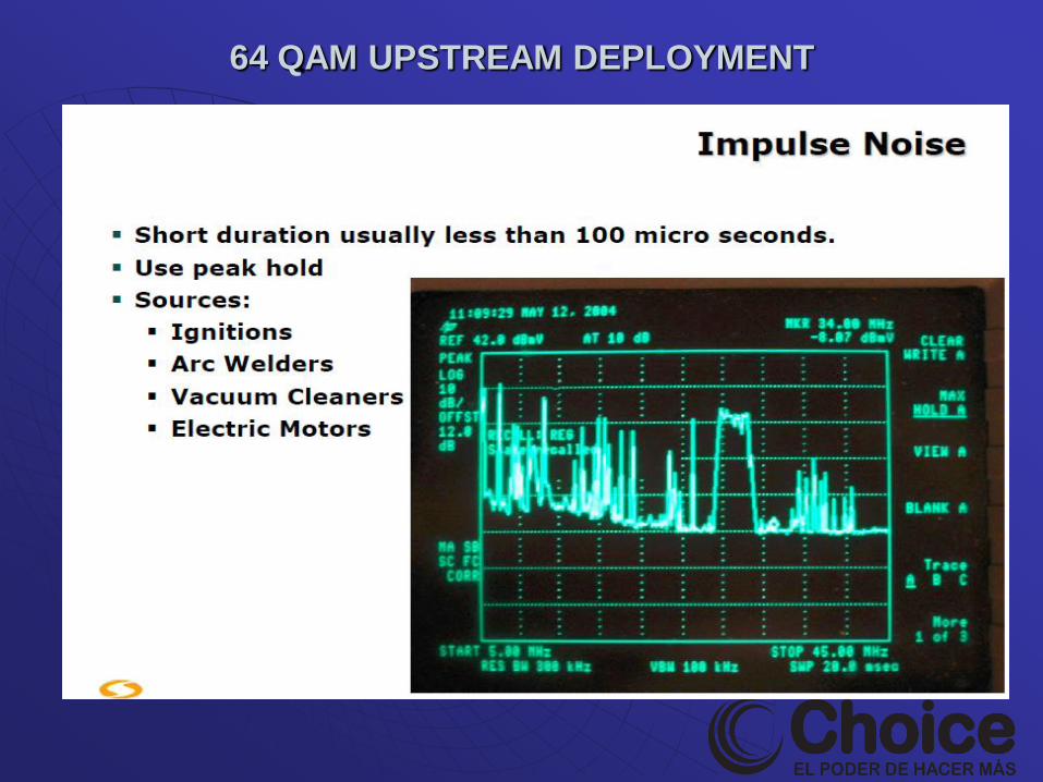
64 QAM UPSTREAM DEPLOYMENT
Impact of BER on 64QAM upstream signal.
Bit Error Rate (BER) is an important concept to understand in any digital transmission system since it is a major indicator of the quality of the digital system.
As data is transmitted some of the bits may not be reproduced at the receiver correctly. The more bits that are incorrect, the more the signal will be affected.
BER is a ratio of incorrect bits to the total number of bits measured.
Its important to know what portion of the bits are in error so you can determine how much margin the system has before failure.
64 QAM UPSTREAM DEPLOYMENT
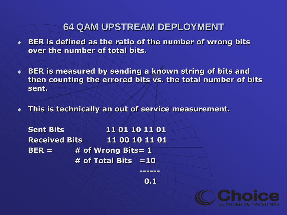
BER is defined as the ratio of the number of wrong bits over the number of total bits.
BER is measured by sending a known string of bits and then counting the errored bits vs. the total number of bits sent.
This is technically an out of service measurement.
Sent Bits 11 01 10 11 01
Received Bits 11 00 10 11 01
BER = # of Wrong Bits= 1
# of Total Bits =10
------
0.1
64 QAM UPSTREAM DEPLOYMENT
64 QAM UPSTREAM DEPLOYMENT
64 QAM UPSTREAM DEPLOYMENT
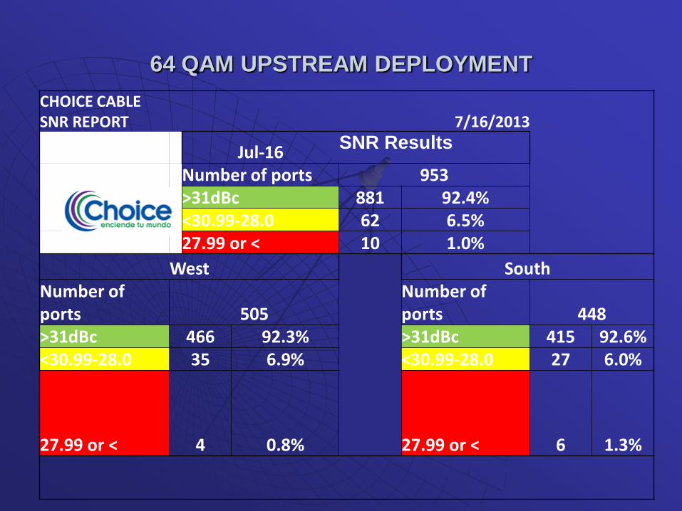
CHOICE CABLE SNR REPORT 7/16/2013
Jul-16 SNR Results
Number of ports 953
>31dBc 881 92.4%
<30.99-28.0 62 6.5%
27.99 or < 10 1.0%
West South Number of ports 505
Number of ports 448
>31dBc 466 92.3% >31dBc 415 92.6% <30.99-28.0 35 6.9% <30.99-28.0 27 6.0%
27.99 or < 4 0.8% 27.99 or < 6 1.3%
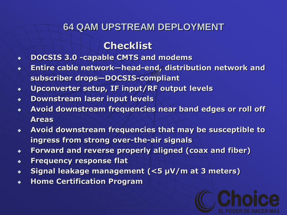
Checklist DOCSIS 3.0 -capable CMTS and modems
Entire cable network—head-end, distribution network and
subscriber drops—DOCSIS-compliant
Upconverter setup, IF input/RF output levels
Downstream laser input levels
Avoid downstream frequencies near band edges or roll off
Areas
Avoid downstream frequencies that may be susceptible to
ingress from strong over-the-air signals
Forward and reverse properly aligned (coax and fiber)
Frequency response flat
Signal leakage management (<5 μV/m at 3 meters)
Home Certification Program
64 QAM UPSTREAM DEPLOYMENT
Final
Questions?
64 QAM UPSTREAM DEPLOYMENT