Embed Size (px)
Citation preview

Available at: http://www.fema.gov/plan/prevent/earthquake/fema74/ Last Modified: January 2011
FEMA E-74 6: Seismic Protection of Nonstructural Components Page 6-247
6.4 MECHANICAL, ELECTRICAL, AND PLUMBING COMPONENTS
6.4.3 PRESSURE PIPING
6.4.3.4 PIPE RISERS
This category covers pipe risers for pressure piping, that is, vertical runs of pressurized piping such as those used in multistory buildings. Risers are typically supported by a combination of wall-mounted supports and additional floor-mounted or roof-mounted supports at the locations of penetrations. Due to their length, thermal movement may be an important consideration and seismic restraints must be designed to accommodate the anticipated inter-story drift and the thermal movement.
TYPICAL CAUSES OF DAMAGE
Pipe risers must be designed to accommodate inter-story drift between adjacent floors, that is, differential movement between the points of support located on different floors of the building. If the pipe supports are not designed to accommodate this movement during an earthquake, the supports may fail or the pipes or pipe joints may fail and leak. Improperly supported pipes can become dislodged and fall; unbraced risers can sway and impact adjacent items.
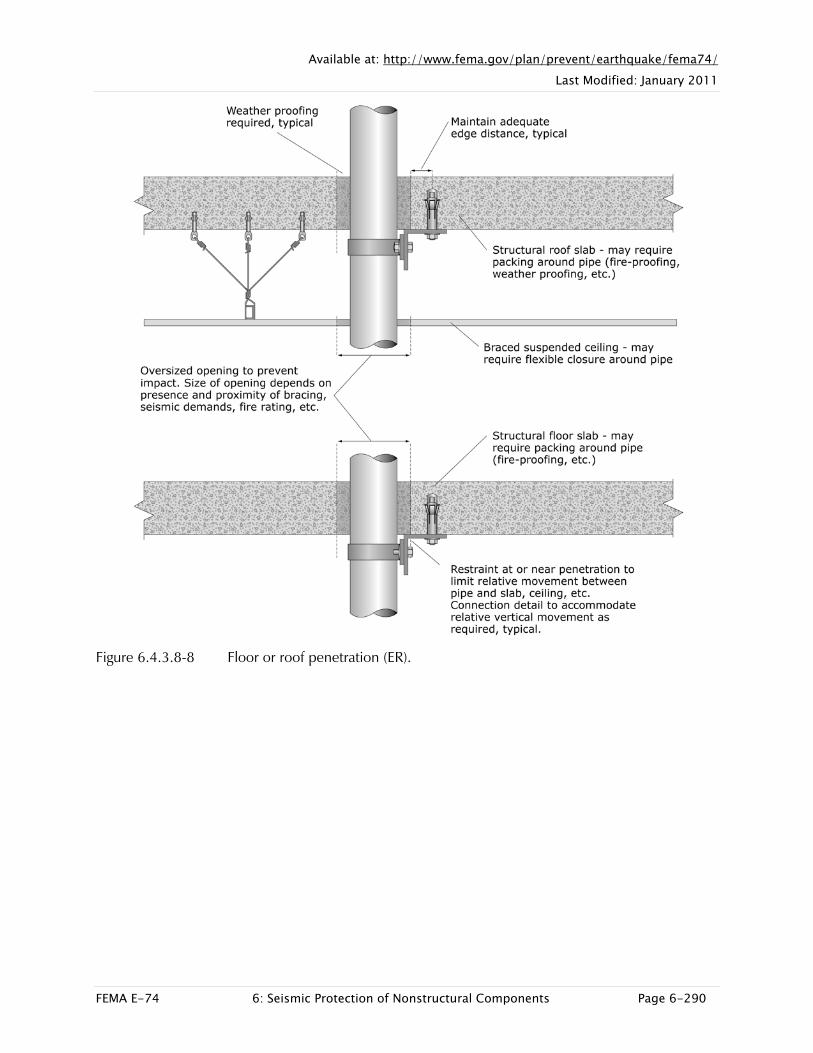
Pipes are vulnerable at penetrations, thus floor and roof penetrations must be sufficiently oversized to prevent impact. Unrestrained movement of pipes at penetrations may damage the piping and pipe restraints but may also damage flooring, ceilings, partitions, insulation, fire-proofing or other architectural finishes. For insulated risers, the piping insulation may also be damaged if the pipe chafes at the restraint. If risers are mounted to lightweight partitions, the partitions may be damaged unless they have been designed and braced to resist the piping loads.
Because risers often involve very long pipe runs, the thermal movement may be significant. Unless seismic restraints are designed to accommodate thermal movement, the piping, pipe joints or rigid seismic restraints could be damaged under operating conditions and fail to perform properly in an earthquake.
Pipe risers in multistory buildings are typically located in utility shafts or pipe chases; thus, they usually do not pose a significant falling hazard to occupants but riser damage could cause significant leakage resulting in property losses and business outage.

Available at: http://www.fema.gov/plan/prevent/earthquake/fema74/ Last Modified: January 2011
FEMA E-74 6: Seismic Protection of Nonstructural Components Page 6-248
Damage Examples
Figure 6.4.3.4-1 Movement of unbraced risers damaged ceiling finishes and insulation in the 1994 magnitude-6.7 Northridge Earthquake (Photo courtesy of Mason Industries).
SEISMIC MITIGATION CONSIDERATIONS
See the general discussion of pipe bracing in Section 6.4.3.1. Standard steel pipe expands or contracts at a rate of 0.8 inch per 100 feet per 100
degrees Fahrenheit; supports and bracing for tall risers or piping subject to large temperature variations must be explicitly designed to accommodate thermal movement. Riser details for chilled water piping may need to accommodate additional insulation. Riser calculations should be performed assuming the full weight of water is at the bottom of the pipe riser.
Pipe risers require vertical support (longitudinal restraints) as well as lateral bracing. Risers are typically supported and braced by a combination of wall-mounted restraints and floor- or roof-mounted supports or guides at the locations of penetrations. They

Available at: http://www.fema.gov/plan/prevent/earthquake/fema74/ Last Modified: January 2011
FEMA E-74 6: Seismic Protection of Nonstructural Components Page 6-249
may also be supported by hangers located on horizontal branch lines within 24 inches of the centerline of the riser. Suspended support details are sometimes used at the top of the riser. The pipes may be rigidly mounted, for instance at the base of the riser, or mounted with elastomeric pads, sliding guides or vibration isolation. Specially designed riser clamps are often used to provide vertical support for pipe risers. Isolated piping should be supported independently from rigidly braced piping; rigid pipe attachments to lightweight walls may cause vibration problems under operating conditions.
All vertical risers should have lateral restraints at the top and bottom of the riser and at each intermediate floor at a maximum spacing of 30 foot intervals. When installed as a riser, nonductile piping, such as no-hub cast iron piping, should include joint stabilizers where the joints are unsupported between floors.
Pipe penetrations through structural elements such as beams, walls, and slabs must be coordinated with a structural engineer. Pipe penetrations through nonstructural walls, architectural finishes or roof membranes must be coordinated with an architect. Riser penetrations may require thermal insulation, fire proofing, sound proofing or weather proofing and unless properly detailed, these architectural and safety features may be compromised during an earthquake. See Section 6.4.3.8 for additional information about detailing pipe penetrations.
Available at: http://www.fema.gov/plan/prevent/earthquake/fema74/ Last Modified: January 2011
FEMA E-74 6: Seismic Protection of Nonstructural Components Page 6-250
Mitigation Examples
Figure 6.4.3.4-2 Riser supports provide lateral restraint with vertical sliding guides that allow thermal movement; restraint hardware consisting of tube sections is welded to either side of pipe (Photo courtesy of Mason Industries).

Available at: http://www.fema.gov/plan/prevent/earthquake/fema74/ Last Modified: January 2011
FEMA E-74 6: Seismic Protection of Nonstructural Components Page 6-251
Figure 6.4.3.4-3 Different schemes for riser supports at floor penetrations with vibration isolation: first one with restraint hardware welded to pipe, second with two sets of riser clamps, and third with riser clamp inside the insulation (Photos courtesy of Mason Industries).

Available at: http://www.fema.gov/plan/prevent/earthquake/fema74/ Last Modified: January 2011
FEMA E-74 6: Seismic Protection of Nonstructural Components Page 6-252
Figure 6.4.3.4-4 Insulated boiler pipe risers with welded lugs (small pipe sections) which travel vertically in guides providing lateral seismic restraint (Photo courtesy of Eduardo Fierro, BFP Engineers).

Available at: http://www.fema.gov/plan/prevent/earthquake/fema74/ Last Modified: January 2011
FEMA E-74 6: Seismic Protection of Nonstructural Components Page 6-253
Mitigation Details
Figure 6.4.3.4-5 Wall-mounted pipe riser restraint/support (ER).

Available at: http://www.fema.gov/plan/prevent/earthquake/fema74/ Last Modified: January 2011
FEMA E-74 6: Seismic Protection of Nonstructural Components Page 6-254
Figure 6.4.3.4-6 Riser restraint/support at floor penetrations – variations with pipe clamp, vibration isolation, and sliding guides (ER).

Available at: http://www.fema.gov/plan/prevent/earthquake/fema74/ Last Modified: January 2011
FEMA E-74 6: Seismic Protection of Nonstructural Components Page 6-255
Figure 6.4.3.4-7 Riser restraint/support at roof penetration – variations with U-bolt or pipe clamp (ER).

Available at: http://www.fema.gov/plan/prevent/earthquake/fema74/ Last Modified: January 2011
FEMA E-74 6: Seismic Protection of Nonstructural Components Page 6-256
Figure 6.4.3.4-8 Roof penetration with vibration isolation (ER).

Available at: http://www.fema.gov/plan/prevent/earthquake/fema74/ Last Modified: January 2011
FEMA E-74 6: Seismic Protection of Nonstructural Components Page 6-257
6.4 MECHANICAL, ELECTRICAL, AND PLUMBING COMPONENTS
6.4.3 PRESSURE PIPING
6.4.3.5 FLOOR-MOUNTED SUPPORTS
This category covers floor-mounted supports for pressure piping. Floor-mounted supports may be used to support either horizontal or vertical pipe runs with or without vibration isolation, either indoors or outdoors. Floor-mounted supports typically involve steel shapes anchored to structural framing or a structural concrete slab. These supports may have one cantilevered support member, one propped cantilever member, or be built up of multiple elements to form a trapeze or braced frame.
TYPICAL CAUSES OF DAMAGE
Failure of pipe supports may result in damage to the support in question, damage to adjacent supports which are overloaded due to the initial failure, damage to the piping or pipe joints, damage to insulation, leakage of the contents, and outage of the system that the pipes support. Joints may fail if the layout of the seismic restraints is poor or where the restraints are inadequate for the anticipated forces and displacements. Piping damage may occur at building separations, seismic joints, or penetrations if the piping has not been detailed to account for the differential movement.
Several failure mechanisms exist for floor-mounted supports: failure at base if anchorage is undersized, yielding of cantilever elements causing excessive deflection, and buckling of braced elements if braces are undersized.
Unrestrained piping supported directly on the floor is vulnerable to damage due to excessive movement. Section 6.4.3.8 provides more information about potential damage at pipe penetrations.
Low lying piping, regardless of the mounting details, is vulnerable to damage due to items falling from above. Pipes may be knocked loose or crushed if heavy items fall on them.

Available at: http://www.fema.gov/plan/prevent/earthquake/fema74/ Last Modified: January 2011
FEMA E-74 6: Seismic Protection of Nonstructural Components Page 6-258
Damage Examples
Figure 6.4.3.5-1 Pipe and support assembly seem intact but photo shows evidence of longitudinal movement of the pipe in the U-bolts (Photo courtesy of BFP Engineers). A rubber pad was installed between the U-bolt and pipe in order to increase the friction coefficient, but was not sufficient to provide longitudinal restraint.

Available at: http://www.fema.gov/plan/prevent/earthquake/fema74/ Last Modified: January 2011
FEMA E-74 6: Seismic Protection of Nonstructural Components Page 6-259
Figure 6.4.3.5-2 Damage to piping, stud wall and finishes due to movement of poorly restrained floor-mounted piping in the 1994 magnitude-6.7 Northridge Earthquake (Photo courtesy of Mason Industries).
SEISMIC MITIGATION CONSIDERATIONS
Horizontal and vertical pipe runs need vertical, lateral, and longitudinal restraints. Floor-mounted supports can be used to provide restraint for any combination of these loads, can be designed for many different configurations, may be used with or without vibration isolation, and may be used either indoors or outdoors.
Longitudinal restraints require positive support to the pipe with a pipe clamp or welded lug; U-bolts do not provide sufficient longitudinal restraint, as observed in Figure 6.4.3.5-1. For insulated piping, longitudinal restraint hardware may need to be located beneath the insulation in order to prevent longitudinal slip.
In an existing concrete slab, care must be taken to locate rebar or post-tensioned tendons prior to drilling holes for anchor bolts. If the base plate for the pipe support is near the edge of a concrete curb or slab, care must be taken to provide sufficient edge distance and embedment for the anchor bolts. Some types of anchors are not recommended for use with vibratory loads. FEMA 414, Installing Seismic Restraints for
Available at: http://www.fema.gov/plan/prevent/earthquake/fema74/ Last Modified: January 2011
FEMA E-74 6: Seismic Protection of Nonstructural Components Page 6-260
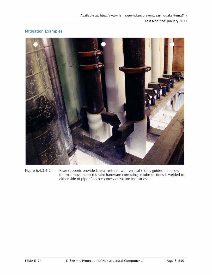
Duct and Pipe (2004) provides additional precautions regarding the installation of anchor bolts and general guidance on pipe restraints.
Mitigation Examples
Figure 6.4.3.5-3 Floor-mounted supports for insulated pipe with vibration isolation (Photo courtesy of Mason Industries).

Available at: http://www.fema.gov/plan/prevent/earthquake/fema74/ Last Modified: January 2011
FEMA E-74 6: Seismic Protection of Nonstructural Components Page 6-261
Figure 6.4.3.5-4 Floor/ground-mounted supports for industrial piping in Chile; piping undamaged in the 2010 magnitude-8.8 Chile Earthquake. Pipe supports include concrete pedestal, base plate, and built-up welded support stand. (Photos courtesy of Antonio Iruretagoyena, Rubén Boroschek & Associates).

Available at: http://www.fema.gov/plan/prevent/earthquake/fema74/ Last Modified: January 2011
FEMA E-74 6: Seismic Protection of Nonstructural Components Page 6-262
Figure 6.4.3.5-5 Floor-mounted supports for industrial piping in Chile; piping undamaged in the 2010 Chile Earthquake. The Chilean Industrial Code (Norma Chilena 2369) requires that shear forces be resisted by shear keys as shown; lower photo is detail of piping at upper right (Photos courtesy of Antonio Iruretagoyena, Rubén Boroschek & Associates).

Available at: http://www.fema.gov/plan/prevent/earthquake/fema74/ Last Modified: January 2011
FEMA E-74 6: Seismic Protection of Nonstructural Components Page 6-263
Mitigation Details
Figure 6.4.3.5-6 Floor-mounted single vertical pipe support (ER).

Available at: http://www.fema.gov/plan/prevent/earthquake/fema74/ Last Modified: January 2011
FEMA E-74 6: Seismic Protection of Nonstructural Components Page 6-264
Figure 6.4.3.5-7 Floor-mounted pipe stand (strut frame) (ER).

Available at: http://www.fema.gov/plan/prevent/earthquake/fema74/ Last Modified: January 2011
FEMA E-74 6: Seismic Protection of Nonstructural Components Page 6-265
Figure 6.4.3.5-8 Floor-mounted pipe stand (steel shapes) (ER).

Available at: http://www.fema.gov/plan/prevent/earthquake/fema74/ Last Modified: January 2011
FEMA E-74 6: Seismic Protection of Nonstructural Components Page 6-266
6.4 MECHANICAL, ELECTRICAL, AND PLUMBING COMPONENTS
6.4.3 PRESSURE PIPING
6.4.3.6 ROOF-MOUNTED SUPPORTS
This category covers roof-mounted supports for pressure piping. Roof-mounted supports may be used to support either horizontal or vertical pipe runs. Roof-mounted supports consist of wood blocking or steel shapes anchored to structural framing or a structural concrete slab and may be mounted with or without vibration isolation. These supports may be flush with the roof surface, have one cantilevered support member, one propped cantilever member, or be built up of multiple elements to form a trapeze or braced frame.
TYPICAL CAUSES OF DAMAGE
Failure of pipe supports may result in damage to the support in question, damage to adjacent supports which are overloaded due to the initial failure, damage to the piping, damage to insulation or roofing, leakage of the contents, and outage of the system that the pipes support. Joints may fail if the layout of the seismic restraints is poor or where the restraints are inadequate for the anticipated forces and displacements. Piping damage may occur at locations where piping runs across roof separations or seismic joints if the piping has not been detailed to account for the differential movement.
Seismic accelerations are often highest at the roof level and thus roof-mounted items are particularly vulnerable to failure unless properly designed. Several failure mechanisms exist for roof-mounted supports: failure at base if anchorage is undersized, yielding of cantilever elements causing excessive deflection, and buckling of braced elements if braces are undersized.
Unrestrained piping supported directly on the roof is vulnerable to damage due to excessive movement. Unanchored wood sleepers may overturn or slide.
Damage to roof-mounted items may also result in damage to the roofing membrane causing subsequent water damage.
Available at: http://www.fema.gov/plan/prevent/earthquake/fema74/ Last Modified: January 2011
FEMA E-74 6: Seismic Protection of Nonstructural Components Page 6-267
Damage Examples
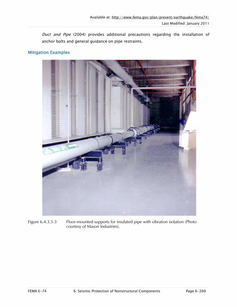
Figure 6.4.3.6-1 Damaged supports and piping on roof-mounted HVAC unit in the 1994 magnitude-6.7 Northridge Earthquake (Photo courtesy of Mason Industries). Both the roof-mounted wood sleepers and strut supports failed.

Available at: http://www.fema.gov/plan/prevent/earthquake/fema74/ Last Modified: January 2011
FEMA E-74 6: Seismic Protection of Nonstructural Components Page 6-268
Figure 6.4.3.6-2 Unrestrained wood sleepers on roof-mounted piping slid a foot in either
direction in 2010 magnitude-6.5 Eureka Earthquake (Photos courtesy of Maryann Phipps, Estructure).

Available at: http://www.fema.gov/plan/prevent/earthquake/fema74/ Last Modified: January 2011
FEMA E-74 6: Seismic Protection of Nonstructural Components Page 6-269
Figure 6.4.3.6-3 Unrestrained roof-mounted piping broke at the connection to the equipment in the 2010 Eureka Earthquake. Piping mounted on wood sleepers should typically be restrained to the roof, not free to slide (Photo courtesy of Maryann Phipps, Estructure).
SEISMIC MITIGATION CONSIDERATIONS
Pipe runs need vertical, lateral and longitudinal restraints. Roof-mounted supports can be used to provide restraint for any combination of these loads, can be designed for many different configurations, and may be used with or without vibration isolation. Longitudinal restraints require positive support to the pipe with a pipe clamp or welded lug; U-bolts do not provide effective longitudinal restraint.
Seismic accelerations are often highest at the roof level; roof-mounted supports may need to be more robust than those located elsewhere in a building. They additionally need to be protected from corrosion and deterioration or they will be ineffective during an earthquake.
In an existing concrete roof slab, care must be taken to locate rebar or post-tensioned tendons prior to drilling holes for anchor bolts. If the base plate for the pipe support is near the edge of a concrete curb or slab, care must be taken to provide sufficient edge distance and embedment for the anchor bolts. Some types of anchors are not

Available at: http://www.fema.gov/plan/prevent/earthquake/fema74/ Last Modified: January 2011
FEMA E-74 6: Seismic Protection of Nonstructural Components Page 6-270
recommended for use with vibratory loads. FEMA 414, Installing Seismic Restraints for Duct and Pipe (2004) provides additional precautions regarding the installation of anchor bolts.
Weatherproofing is an important consideration for roof-mounted supports; any penetration of the roof membrane must be adequately sealed to prevent roof leakage. Refer to Section 6.4.3.8 for additional discussion of pipe penetrations.
Seismic restraint hardware for any exterior exposure should be specified using materials or coatings to reduce corrosion and may require periodic painting or replacement to maintain the effectiveness of the restraint. Items exposed to salt air, or deicing compounds such as in a parking structure, may be especially at risk.
Mitigation Examples
Figure 6.4.3.6-4 Roof-mounted supports with vibration isolation (Photo courtesy of Mason Industries).
Available at: http://www.fema.gov/plan/prevent/earthquake/fema74/ Last Modified: January 2011
FEMA E-74 6: Seismic Protection of Nonstructural Components Page 6-271
Mitigation Details
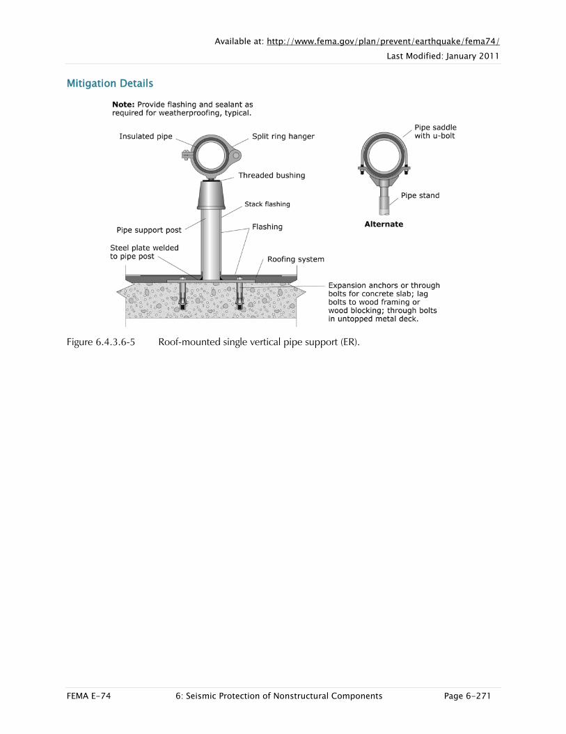
Figure 6.4.3.6-5 Roof-mounted single vertical pipe support (ER).

Available at: http://www.fema.gov/plan/prevent/earthquake/fema74/ Last Modified: January 2011
FEMA E-74 6: Seismic Protection of Nonstructural Components Page 6-272
Figure 6.4.3.6-6 Roof-mounted pipe stand (ER).
Available at: http://www.fema.gov/plan/prevent/earthquake/fema74/ Last Modified: January 2011
FEMA E-74 6: Seismic Protection of Nonstructural Components Page 6-273
6.4 MECHANICAL, ELECTRICAL, AND PLUMBING COMPONENTS
6.4.3 PRESSURE PIPING
6.4.3.7 WALL-MOUNTED SUPPORTS
This category covers wall-mounted supports for pressure piping. Wall-mounted supports may be used to support either horizontal or vertical pipe runs, may be used with or without vibration isolation, and may be used either indoors or outdoors. Wall-mounted supports may be mounted flush or be built up out of assemblies of steel shapes anchored to structural framing or a structural wall.
TYPICAL CAUSES OF DAMAGE
Failure of pipe supports may result in damage to the support in question, damage to adjacent supports which are overloaded due to the initial failure, damage to the piping or pipe joints, damage to insulation, leakage of the contents, and outage of the system that the pipes support.
Joints may fail if the layout of the seismic restraints is poor or where the restraints are inadequate for the anticipated forces and displacements. Piping damage may occur at building separations or seismic joints if the piping has not been detailed to account for the differential movement. Wall-mounted piping often passes thru penetrations; piping may be vulnerable unless the penetrations are properly detailed.
Several failure mechanisms exist for wall-mounted supports: failure at wall plate if anchorage is undersized, yielding of cantilever elements causing excessive deflection, and buckling of braced elements if braces are undersized. Piping attached to nonstructural walls or walls of insufficient strength may also result in damage to the wall or partition and the architectural finishes or fire-proofing.

Available at: http://www.fema.gov/plan/prevent/earthquake/fema74/ Last Modified: January 2011
FEMA E-74 6: Seismic Protection of Nonstructural Components Page 6-274
Damage Examples
Figure 6.4.3.7-1 Wall-mounted supports for horizontal and vertical pipe runs with exterior exposure. Photo shows minor damage at wall penetration of green pipe and minor movement at some U-bolts, but restraints generally performed well (Photo courtesy of Eduardo Fierro, BFP Engineers). Note that lateral restraint near an elbow can be used to provide longitudinal restraint for a perpendicular pipe run.

Available at: http://www.fema.gov/plan/prevent/earthquake/fema74/ Last Modified: January 2011
FEMA E-74 6: Seismic Protection of Nonstructural Components Page 6-275
Figure 6.4.3.7-2 Pipe supports attached to wall of damaged silo (Photo courtesy of Eduardo Fierro, BFP Engineers). In spite of structural damage to silo, cast-in-place pipe supports were still intact and the piping did not fall.
SEISMIC MITIGATION CONSIDERATIONS
Horizontal and vertical pipe runs need vertical, lateral and longitudinal restraints. Wall-mounted supports can be used to provide restraint for any combination of these loads, can be designed for many different configurations, may be used with or without vibration isolation, and may be used either indoors or outdoors. Pipes may be mounted flush to the wall or offset; make sure to check that the wall or partition is capable of carrying the piping loads and will not develop vibration problems.
Longitudinal restraints require positive support to the pipe with a pipe clamp or welded lug; U-bolts do not provide sufficient longitudinal restraint. For insulated piping, longitudinal restraint hardware may need to be located beneath the insulation in order to prevent longitudinal slip.
In an existing concrete or masonry wall, care must be taken to locate rebar prior to drilling holes for anchor bolts so the rebar is not cut. Anchorage for isolated piping should be independent of anchorage for rigidly mounted pipe. In addition, some types of anchors are not recommended for use with vibratory loads. FEMA 414, Installing Seismic Restraints for Duct and Pipe (2004), provides additional precautions regarding the installation of anchor bolts and general guidance on pipe restraints.

Available at: http://www.fema.gov/plan/prevent/earthquake/fema74/ Last Modified: January 2011
FEMA E-74 6: Seismic Protection of Nonstructural Components Page 6-276
Mitigation Examples
Figure 6.4.3.7-3 Wall-mounted pipe restraint examples using standard strut shapes and connectors (Photo courtesy of Cynthia Perry, BFP Engineers). Bottom view still under construction; pipes temporarily attached with plastic ties.

Available at: http://www.fema.gov/plan/prevent/earthquake/fema74/ Last Modified: January 2011
FEMA E-74 6: Seismic Protection of Nonstructural Components Page 6-277
Mitigation Details
Figure 6.4.3.7-4 Surface-mount to structural wall (ER).

Available at: http://www.fema.gov/plan/prevent/earthquake/fema74/ Last Modified: January 2011
FEMA E-74 6: Seismic Protection of Nonstructural Components Page 6-278
Figure 6.4.3.7-5 Wall-mount with steel shape or struts welded to concrete wall (ER).

Available at: http://www.fema.gov/plan/prevent/earthquake/fema74/ Last Modified: January 2011
FEMA E-74 6: Seismic Protection of Nonstructural Components Page 6-279
Figure 6.4.3.7-6 Wall-mount using strut channels to metal stud wall (ER).

Available at: http://www.fema.gov/plan/prevent/earthquake/fema74/ Last Modified: January 2011
FEMA E-74 6: Seismic Protection of Nonstructural Components Page 6-280
Figure 6.4.3.7-7 Wall-mount to stud wall with pre-manufactured brackets (ER).
Available at: http://www.fema.gov/plan/prevent/earthquake/fema74/ Last Modified: January 2011
FEMA E-74 6: Seismic Protection of Nonstructural Components Page 6-281
6.4 MECHANICAL, ELECTRICAL, AND PLUMBING COMPONENTS
6.4.3 PRESSURE PIPING
6.4.3.8 PENETRATIONS
This section addresses locations where pressure piping passes through floor, roof, or wall penetrations in either architectural or structural components. Penetrations usually fall into one of three categories: 1) the penetration is sufficiently oversized to prevent impact between the pipe and surrounding wall or slab; 2) a seismic restraint is located at or near the penetration so the pipe and surrounding wall or slab are constrained to move together; or 3) the penetration is not properly detailed and becomes an unintended restraint in the piping run which may result in damage to the piping, wall, slab, or finishes. Structural and nonstructural elements may require strengthening around penetrations or may need special detailing to provide fire-proofing, sound-proofing, and weather-proofing or improve the appearance of architectural finishes.
TYPICAL CAUSES OF DAMAGE
Pipe movement at penetrations often results in damage to architectural finishes, fire-proofing, and insulation. Failure of joints at or near penetrations may result in leakage causing further damage to these components.
Where pipes pass through unreinforced masonry walls, the opening may create a point of weakness resulting in crack propagation from the opening. Lightweight partitions or ceilings are also frequently damaged by movement of unrestrained piping. Pipe movement at penetrations may also result in damage to electrical lines in the wall or ceiling space.

Available at: http://www.fema.gov/plan/prevent/earthquake/fema74/ Last Modified: January 2011
FEMA E-74 6: Seismic Protection of Nonstructural Components Page 6-282
Damage Examples
Figure 6.4.3.8-1 Damage to ceilings, gypsum board partitions, fire-proofing, and insulation in the 1994 magnitude-6.7 Northridge Earthquake (Photo courtesy of Mason Industries). Note that the blue piping has joints located in the wall space which leaked, resulting in additional damage.

Available at: http://www.fema.gov/plan/prevent/earthquake/fema74/ Last Modified: January 2011
FEMA E-74 6: Seismic Protection of Nonstructural Components Page 6-283
Figure 6.4.3.8-2 Exterior stucco damage at wall penetration for fire protection piping in the 2001 magnitude-8.4 Peru Earthquake (Photos courtesy of Eduardo Fierro, : BFP Engineers).
Available at: http://www.fema.gov/plan/prevent/earthquake/fema74/ Last Modified: January 2011
FEMA E-74 6: Seismic Protection of Nonstructural Components Page 6-284
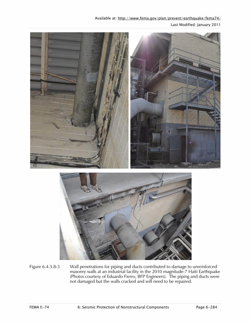
Figure 6.4.3.8-3 Wall penetrations for piping and ducts contributed to damage to unreinforced masonry walls at an industrial facility in the 2010 magnitude-7 Haiti Earthquake (Photos courtesy of Eduardo Fierro, BFP Engineers). The piping and ducts were not damaged but the walls cracked and will need to be repaired.

Available at: http://www.fema.gov/plan/prevent/earthquake/fema74/ Last Modified: January 2011
FEMA E-74 6: Seismic Protection of Nonstructural Components Page 6-285
SEISMIC MITIGATION CONSIDERATIONS
As described above, there are two different approaches for avoiding damage at pipe penetrations. Either the penetration should be designed to be oversized to avoid contact between the pipe and the wall or slab, or the pipe should be restrained at or near the penetration so the pipe and wall or slab are constrained to move together.
Penetrations should be oversized wherever possible to allow for differential movement of pipe supports and the structural elements they are attached to on either side of the wall, floor, or roof slab. Alternatively, lateral restraints for the piping should be provided close to the penetration to prevent impact between the pipe and the opening. Where piping crosses from one building to another, flexible connections may also be required near the penetration.
Pipes often fail or leak at joints; pipe joints should be not be located within penetrations where they will leak into a wall cavity or are inaccessible for inspection and repair.
Penetrations through structural walls, slabs, or framing must be coordinated with a structural engineer; structural walls, slabs, or framing elements may require strengthening around penetrations. For large openings such as a pipe chase, this may involve extra trim steel around the opening or additional framing members beneath a slab. Penetrations in a structural steel girder may require welded reinforcement plates around the opening. For locating penetrations in existing concrete or masonry walls or concrete slabs, care must be taken to locate rebar or post-tensioned tendons prior to drilling holes for pipe penetrations so these elements are not cut.
Penetrations through nonstructural walls should be coordinated with an architect to ensure that fire-proofing, sound-proofing, weather-proofing, insulation requirements and finishes on either side of the opening are not compromised. Roof penetrations have particular issues related to weather-proofing and corrosion protection; care must be taken to avoid leakage at roof penetrations. Where penetrations pass through weak materials such as unreinforced masonry or lightweight partitions, these elements may require strengthening.
Detailing at penetrations often involves several layers of material and finishes each of which require attention; penetrations through structural elements may involve both the engineer and the architect. For instance, a penetration through a masonry wall with interior plaster and exterior stucco will require detailing for all three of these materials. The damage shown in Figure 6.4.3.8-2 occurred because although the masonry penetration was oversized and filled with packing, the exterior stucco was placed flush with the pipe resulting in stucco damage during the earthquake.

Available at: http://www.fema.gov/plan/prevent/earthquake/fema74/ Last Modified: January 2011
FEMA E-74 6: Seismic Protection of Nonstructural Components Page 6-286
Pipe risers that pass through floor and roof penetrations must be detailed so the seismic restraints can also accommodate longitudinal thermal movement of the pipe. If allowance for thermal movement is not included in the design, the seismic restraints may be damaged under operating conditions and fail to perform properly in an earthquake.
Penetrations in exit corridors needed for emergency egress may warrant special care; similarly, penetrations in boiler rooms or locations with fuel lines or hazardous materials may also warrant special detailing to maintain the fire-proofing of the space in the event of a post-earthquake fire.
FEMA 414, Installing Seismic Restraints for Duct and Pipe (2004), provides additional precautions regarding the installation of anchor bolts and general guidance on pipe restraints.
Mitigation Examples
Figure 6.4.3.8-4 Wall penetrations with lateral restraints at trapeze in foreground, flexible couplings with independent vertical supports, and sealant at each wall penetration (Photo courtesy of Mason Industries).

Available at: http://www.fema.gov/plan/prevent/earthquake/fema74/ Last Modified: January 2011
FEMA E-74 6: Seismic Protection of Nonstructural Components Page 6-287
Figure 6.4.3.8-5 Floor penetration with oversized opening and vertical and lateral restraints immediately above floor (Photo courtesy of Mason Industries).

Available at: http://www.fema.gov/plan/prevent/earthquake/fema74/ Last Modified: January 2011
FEMA E-74 6: Seismic Protection of Nonstructural Components Page 6-288
Figure 6.4.3.8-6 Series of pipe penetrations through a full-height CMU partition wall. Note pipe suspended from floor above; partition anchored to floor below and detailed with steel clip angles intended to provide lateral restraint for the wall but allow relative slip between the wall and slab above. The hangers will move with the floor above and the pipe at penetration will move with the wall. Lateral restraints are located immediately above floor (Photo courtesy Cynthia Perry, BFP Engineers).

Available at: http://www.fema.gov/plan/prevent/earthquake/fema74/ Last Modified: January 2011
FEMA E-74 6: Seismic Protection of Nonstructural Components Page 6-289
Mitigation Details
Figure 6.4.3.8-7 Wall penetration (ER).
Available at: http://www.fema.gov/plan/prevent/earthquake/fema74/ Last Modified: January 2011
FEMA E-74 6: Seismic Protection of Nonstructural Components Page 6-290
Figure 6.4.3.8-8 Floor or roof penetration (ER).

Available at: http://www.fema.gov/plan/prevent/earthquake/fema74/ Last Modified: January 2011
FEMA E-74 6: Seismic Protection of Nonstructural Components Page 6-291
6.4 MECHANICAL, ELECTRICAL, AND PLUMBING COMPONENTS
6.4.4 FIRE PROTECTION PIPING
6.4.4.1 SUSPENDED FIRE PROTECTION PIPING
This category covers fire protection sprinkler systems and piping. These systems and piping are subject to the requirements in NFPA 13, Standard Installation of Sprinkler Systems (NFPA, 2007a). In some seismic zones (Design Categories C, D, E, and F), additional requirements in ASCE/SEI 7-10, Minimum Design Loads for Buildings and other Structures (ASCE, 2010), may apply.
TYPICAL CAUSES OF DAMAGE
Fire protection piping systems are sensitive to both acceleration and deformation. Vulnerable locations include joints, bends, connections to rigidly mounted equipment and risers subjected to significant relative movement between floors.
Sprinkler heads are often damaged due to conflict with ceiling systems; this conflict may also result in impact damage to the ceiling or subsequent water damage.
Fluids may leak from damaged joints or broken pipe; property losses and business outages are often attributed to fluid leaks from fire suppression piping. Facilities may need to be evacuated if the fire suppression system is compromised.
Damage to any part of the fire protection system may compromise its functionality; in addition to the piping, the pumps, holding tanks, control panels, control sensors, smoke detection equipment, fire doors, etc. must all be operational. If a fire breaks out following an earthquake and the fire suppression system is not functional, significant property losses may result.

Available at: http://www.fema.gov/plan/prevent/earthquake/fema74/ Last Modified: January 2011
FEMA E-74 6: Seismic Protection of Nonstructural Components Page 6-292
Damage Examples
Figure 6.4.4.1-1 Sprinkler pipe ruptured at the elbow joint due to differential motion within the ceiling plenum. Water leakage from broken fire sprinklers and water lines contributed to the decision to close this hospital for several days following the 1994 magnitude-6.7 Northridge Earthquake (Photo courtesy of Robert Reitherman).

Available at: http://www.fema.gov/plan/prevent/earthquake/fema74/ Last Modified: January 2011
FEMA E-74 6: Seismic Protection of Nonstructural Components Page 6-293
Figure 6.4.4.1-2 Wall-mounted pipe restraint failed due to inadequate connection to structural framing in the 2001 magnitude-8.4 Peru Earthquake (Photo courtesy of Eduardo Fierro, BFP Engineers).
Figure 6.4.4.1-3 Damage to suspended fire protection piping from the 1994 Northridge Earthquake. Failed vibration isolators at left; failed C-clamps without beam clamp restraining straps shown at right (Photos courtesy of Mason Industries).

Available at: http://www.fema.gov/plan/prevent/earthquake/fema74/ Last Modified: January 2011
FEMA E-74 6: Seismic Protection of Nonstructural Components Page 6-294
Figure 6.4.4.1-4 Collapse of water tank at left and broken piping disabled the fire protection system at this power plant in Port-au-Prince and led to the temporary plant closure in the 2010 magnitude-7 Haiti Earthquake (Photo courtesy of Eduardo Fierro, BFP Engineers).
Figure 6.4.4.1-5 Unanchored holding tank slid on concrete pad, breaking fire protection piping and disabling the fire protection system in the 2010 Haiti Earthquake. In this case, the piping was well anchored but the tank was unrestrained (Photo courtesy of Eduardo Fierro, BFP Engineers).
Available at: http://www.fema.gov/plan/prevent/earthquake/fema74/ Last Modified: January 2011
FEMA E-74 6: Seismic Protection of Nonstructural Components Page 6-295
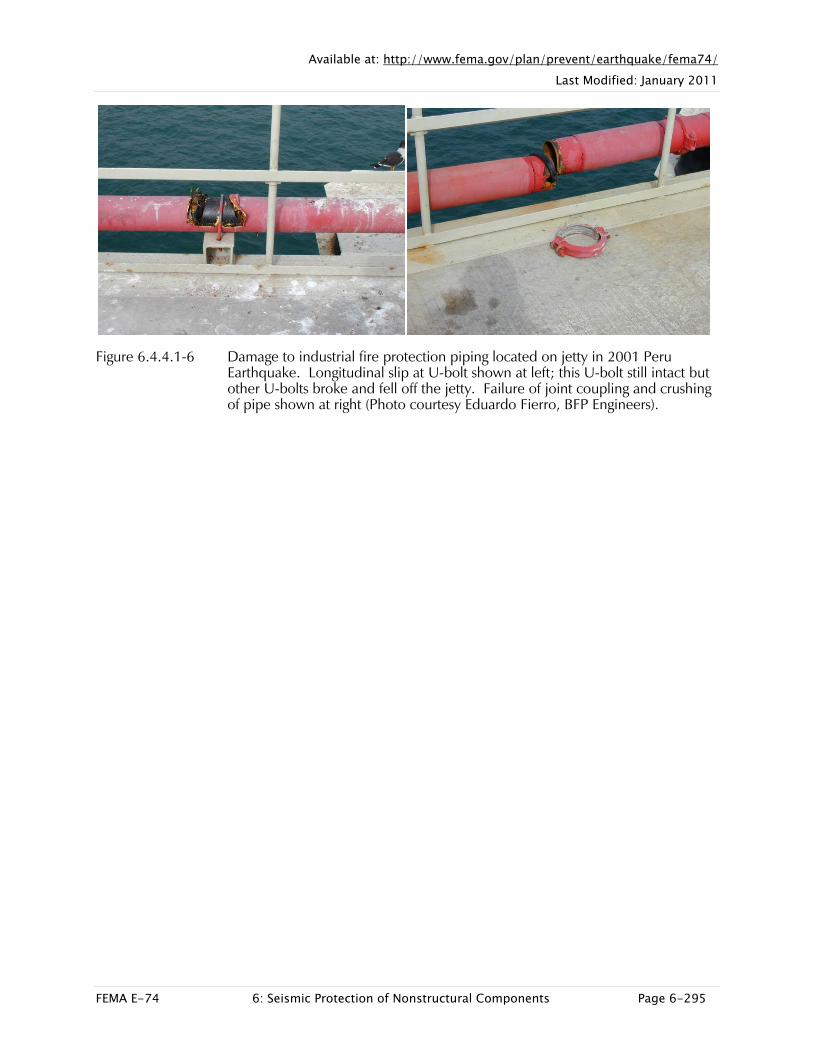
Figure 6.4.4.1-6 Damage to industrial fire protection piping located on jetty in 2001 Peru Earthquake. Longitudinal slip at U-bolt shown at left; this U-bolt still intact but other U-bolts broke and fell off the jetty. Failure of joint coupling and crushing of pipe shown at right (Photo courtesy Eduardo Fierro, BFP Engineers).

Available at: http://www.fema.gov/plan/prevent/earthquake/fema74/ Last Modified: January 2011
FEMA E-74 6: Seismic Protection of Nonstructural Components Page 6-296
Figure 6.4.4.1-7 Conflicts between the sprinkler heads and several types of ceiling finishes resulted in damage to the ceilings, sprinkler heads and subsequent water damage at the Concepción airport in the 2010 magnitude-8.8 Chile Earthquake (Photos courtesy of Rodrigo Retamales, Rubén Boroschek & Associates).

Available at: http://www.fema.gov/plan/prevent/earthquake/fema74/ Last Modified: January 2011
FEMA E-74 6: Seismic Protection of Nonstructural Components Page 6-297
SEISMIC MITIGATION CONSIDERATIONS
ASCE 7-10, Minimum Design Loads for Buildings (ASCE, 2010), Section 13.1.3.1 specifies that systems required for life-safety purposes after an earthquake, such as fire protection systems, be classified as designated seismic systems and designed using a component importance factor, Ip, of 1.5. Designated seismic systems may require engineering calculations, equipment certification, special inspection, etc. Check the jurisdiction and applicable code for other requirements.
NFPA 13, Standard for Installation of Sprinkler Systems (NFPA, 2007a), provides specific requirements for fire suppression systems and piping. Refer to 2006 IBC, International Building Code (ICC, 2006), and ASCE/SEI 7-10 Section 13.6.8 for other seismic design requirements. NFPA 13 contains prescriptive requirements for the layout of fire protection piping, with minimum spacing for vertical, lateral, and longitudinal seismic restraints. While NFPA 13 includes some exemptions for small diameter piping or hangers less than 6” long, these exemptions are not recognized explicitly in the 2006 IBC and may not provide adequate protection in areas of high seismicity. Check with the jurisdiction for applicable requirements and exemptions.
Fire suppression systems include many components, all of which must be properly restrained or anchored for the system to function as intended. Pumps, holding tanks, control panels, control sensors, piping and sprinkler heads must all be protected from earthquake damage. In addition to seismic restraints for each component, it is important to check for potential conflicts with other structural and nonstructural elements and for falling hazards.
Seismic restraint details for pressure piping shown in Sections 6.4.3.1 through 6.4.3.8 can be adapted for use with fire protection piping. One significant difference is that components, supports, and seismic restraint hardware for fire protection systems must all be certified (UL listed, FM approved, etc.). This requirement also applies to seismic restraint components for fire protection control panels, pumps, and holding tanks.
Some proprietary systems are available that reduce the vulnerability of sprinkler heads in suspended ceiling grids. One such system provides flexible sprinkler drops so the sprinkler head can move freely with the ceiling grid (see Figure 6.4.4.1-11); this proprietary system has been shake table tested. Another system is an “integrated” ceiling system where the ceiling grid, acoustical panels, lighting, ducts and air diffusers, and sprinkler piping are all shop assembled in modules; this system alleviates the problem of differential movement of the component parts. These types of solutions may greatly reduce the seismic vulnerability of sprinkler heads. Check the internet for these and other proprietary systems.

Available at: http://www.fema.gov/plan/prevent/earthquake/fema74/ Last Modified: January 2011
FEMA E-74 6: Seismic Protection of Nonstructural Components Page 6-298
Two details are included here that are unique to fire protection systems. Figure 6.4.4.1-11 provides one type of detail for a sprinkler drop and Figure 6.4.4.1-12 provides a detail for an end of line restraint required for feeds or cross mains.
Several engineered seismic bracing systems are commercially available and can be customized for most applications. Check the internet for these proprietary systems and whether they are UL listed, OSHPD approved, FM approved, etc. as required.
For California schools and essential facilities, DSA Policy 10-01, Plan Submittal Requirements: Automatic Fire Sprinkler Systems (AFSS) (California Department of General Services, 2010b), states that as of July 2010, deferred submittals for fire protection systems will no longer be accepted. These systems must be submitted as a complete package as part of the initial project submittal.
Mitigation Examples
Figure 6.4.4.1-8 There was no damage to the fire suppression equipment in this control room in the 2001 Peru Earthquake because the pump and the control panel were well anchored and the piping had flexible connections with adequate sized wall penetration and no overhead falling hazards (Photo courtesy of Eduardo Fierro, BFP Engineers).

Available at: http://www.fema.gov/plan/prevent/earthquake/fema74/ Last Modified: January 2011
FEMA E-74 6: Seismic Protection of Nonstructural Components Page 6-299
Figure 6.4.4.1-9 Transverse and longitudinal restraints on fire protection distribution line (Photo courtesy of Cynthia Perry, BFP Engineers).
Figure 6.4.4.1-10 Flexible hose between sprinkler line and ceiling allowing the sprinkler head to move with the suspended ceiling without causing damage to the sprinkler system (Photo courtesy of Flexhead).

Available at: http://www.fema.gov/plan/prevent/earthquake/fema74/ Last Modified: January 2011
FEMA E-74 6: Seismic Protection of Nonstructural Components Page 6-300
Mitigation Details
Figure 6.4.4.1-11 Flexible sprinkler drop (ER).
Figure 6.4.4.1-12 End of line restraint (ER).