Embed Size (px)
Citation preview
Concepts & ExamplesScreenOS Reference Guide
Administration
Release 6.3.0, Rev. 01
Juniper Networks, Inc.1194 North Mathilda Avenue
Sunnyvale, California 94089
USA
408-745-2000
www.juniper.net
Revision 01Published: 2009-08-20

Juniper Networks, the Juniper Networks logo, JUNOS, NetScreen, ScreenOS, and Steel-Belted Radius are registered trademarks of Juniper Networks, Inc. inthe United States and other countries. JUNOSe is a trademark of Juniper Networks, Inc. All other trademarks, service marks, registered trademarks, orregistered service marks are the property of their respective owners.Juniper Networks assumes no responsibility for any inaccuracies in this document. Juniper Networks reserves the right to change, modify, transfer, orotherwise revise this publication without notice.Products made or sold by Juniper Networks or components thereof might be covered by one or more of the following patents that are owned by or licensedto Juniper Networks: U.S. Patent Nos. 5,473,599, 5,905,725, 5,909,440, 6,192,051, 6,333,650, 6,359,479, 6,406,312, 6,429,706, 6,459,579, 6,493,347,6,538,518, 6,538,899, 6,552,918, 6,567,902, 6,578,186, and 6,590,785.Copyright © 2009, Juniper Networks, Inc.All rights reserved. Printed in USA.
Revision HistoryAugust 2009—Revision 01
Content subject to change. The information in this document is current as of the date listed in the revision history.
SOFTWARE LICENSE
The terms and conditions for using this software are described in the software license contained in the acknowledgment to your purchase order or, to theextent applicable, to any reseller agreement or end-user purchase agreement executed between you and Juniper Networks. By using this software, youindicate that you understand and agree to be bound by those terms and conditions.
Generally speaking, the software license restricts the manner in which you are permitted to use the software and may contain prohibitions against certainuses. The software license may state conditions under which the license is automatically terminated. You should consult the license for further details.
For complete product documentation, please see the Juniper Networks Web site at www.juniper.net/techpubs.
ii ■
END USER LICENSE AGREEMENT
READ THIS END USER LICENSE AGREEMENT (“AGREEMENT”) BEFORE DOWNLOADING, INSTALLING, OR USING THE SOFTWARE. BY DOWNLOADING,INSTALLING, OR USING THE SOFTWARE OR OTHERWISE EXPRESSING YOUR AGREEMENT TO THE TERMS CONTAINED HEREIN, YOU (AS CUSTOMEROR IF YOU ARE NOT THE CUSTOMER, AS A REPRESENTATIVE/AGENT AUTHORIZED TO BIND THE CUSTOMER) CONSENT TO BE BOUND BY THISAGREEMENT. IF YOU DO NOT OR CANNOT AGREE TO THE TERMS CONTAINED HEREIN, THEN (A) DO NOT DOWNLOAD, INSTALL, OR USE THE SOFTWARE,AND (B) YOU MAY CONTACT JUNIPER NETWORKS REGARDING LICENSE TERMS.
1. The Parties. The parties to this Agreement are (i) Juniper Networks, Inc. (if the Customer’s principal office is located in the Americas) or Juniper Networks(Cayman) Limited (if the Customer’s principal office is located outside the Americas) (such applicable entity being referred to herein as “Juniper”), and (ii)the person or organization that originally purchased from Juniper or an authorized Juniper reseller the applicable license(s) for use of the Software (“Customer”)(collectively, the “Parties”).
2. The Software. In this Agreement, “Software” means the program modules and features of the Juniper or Juniper-supplied software, for which Customerhas paid the applicable license or support fees to Juniper or an authorized Juniper reseller, or which was embedded by Juniper in equipment which Customerpurchased from Juniper or an authorized Juniper reseller. “Software” also includes updates, upgrades and new releases of such software. “EmbeddedSoftware” means Software which Juniper has embedded in or loaded onto the Juniper equipment and any updates, upgrades, additions or replacementswhich are subsequently embedded in or loaded onto the equipment.
3. License Grant. Subject to payment of the applicable fees and the limitations and restrictions set forth herein, Juniper grants to Customer a non-exclusiveand non-transferable license, without right to sublicense, to use the Software, in executable form only, subject to the following use restrictions:
a. Customer shall use Embedded Software solely as embedded in, and for execution on, Juniper equipment originally purchased by Customer from Juniperor an authorized Juniper reseller.
b. Customer shall use the Software on a single hardware chassis having a single processing unit, or as many chassis or processing units for which Customerhas paid the applicable license fees; provided, however, with respect to the Steel-Belted Radius or Odyssey Access Client software only, Customer shall usesuch Software on a single computer containing a single physical random access memory space and containing any number of processors. Use of theSteel-Belted Radius or IMS AAA software on multiple computers or virtual machines (e.g., Solaris zones) requires multiple licenses, regardless of whethersuch computers or virtualizations are physically contained on a single chassis.
c. Product purchase documents, paper or electronic user documentation, and/or the particular licenses purchased by Customer may specify limits toCustomer’s use of the Software. Such limits may restrict use to a maximum number of seats, registered endpoints, concurrent users, sessions, calls,connections, subscribers, clusters, nodes, realms, devices, links, ports or transactions, or require the purchase of separate licenses to use particular features,functionalities, services, applications, operations, or capabilities, or provide throughput, performance, configuration, bandwidth, interface, processing,temporal, or geographical limits. In addition, such limits may restrict the use of the Software to managing certain kinds of networks or require the Softwareto be used only in conjunction with other specific Software. Customer’s use of the Software shall be subject to all such limitations and purchase of all applicablelicenses.
d. For any trial copy of the Software, Customer’s right to use the Software expires 30 days after download, installation or use of the Software. Customermay operate the Software after the 30-day trial period only if Customer pays for a license to do so. Customer may not extend or create an additional trialperiod by re-installing the Software after the 30-day trial period.
e. The Global Enterprise Edition of the Steel-Belted Radius software may be used by Customer only to manage access to Customer’s enterprise network.Specifically, service provider customers are expressly prohibited from using the Global Enterprise Edition of the Steel-Belted Radius software to support anycommercial network access services.
The foregoing license is not transferable or assignable by Customer. No license is granted herein to any user who did not originally purchase the applicablelicense(s) for the Software from Juniper or an authorized Juniper reseller.
4. Use Prohibitions. Notwithstanding the foregoing, the license provided herein does not permit the Customer to, and Customer agrees not to and shallnot: (a) modify, unbundle, reverse engineer, or create derivative works based on the Software; (b) make unauthorized copies of the Software (except asnecessary for backup purposes); (c) rent, sell, transfer, or grant any rights in and to any copy of the Software, in any form, to any third party; (d) removeany proprietary notices, labels, or marks on or in any copy of the Software or any product in which the Software is embedded; (e) distribute any copy ofthe Software to any third party, including as may be embedded in Juniper equipment sold in the secondhand market; (f) use any ‘locked’ or key-restrictedfeature, function, service, application, operation, or capability without first purchasing the applicable license(s) and obtaining a valid key from Juniper, evenif such feature, function, service, application, operation, or capability is enabled without a key; (g) distribute any key for the Software provided by Juniperto any third party; (h) use the Software in any manner that extends or is broader than the uses purchased by Customer from Juniper or an authorized Juniperreseller; (i) use Embedded Software on non-Juniper equipment; (j) use Embedded Software (or make it available for use) on Juniper equipment that theCustomer did not originally purchase from Juniper or an authorized Juniper reseller; (k) disclose the results of testing or benchmarking of the Software toany third party without the prior written consent of Juniper; or (l) use the Software in any manner other than as expressly provided herein.
5. Audit. Customer shall maintain accurate records as necessary to verify compliance with this Agreement. Upon request by Juniper, Customer shall furnishsuch records to Juniper and certify its compliance with this Agreement.
■ iii
6. Confidentiality. The Parties agree that aspects of the Software and associated documentation are the confidential property of Juniper. As such, Customershall exercise all reasonable commercial efforts to maintain the Software and associated documentation in confidence, which at a minimum includesrestricting access to the Software to Customer employees and contractors having a need to use the Software for Customer’s internal business purposes.
7. Ownership. Juniper and Juniper’s licensors, respectively, retain ownership of all right, title, and interest (including copyright) in and to the Software,associated documentation, and all copies of the Software. Nothing in this Agreement constitutes a transfer or conveyance of any right, title, or interest inthe Software or associated documentation, or a sale of the Software, associated documentation, or copies of the Software.
8. Warranty, Limitation of Liability, Disclaimer of Warranty. The warranty applicable to the Software shall be as set forth in the warranty statement thataccompanies the Software (the “Warranty Statement”). Nothing in this Agreement shall give rise to any obligation to support the Software. Support servicesmay be purchased separately. Any such support shall be governed by a separate, written support services agreement. TO THE MAXIMUM EXTENT PERMITTEDBY LAW, JUNIPER SHALL NOT BE LIABLE FOR ANY LOST PROFITS, LOSS OF DATA, OR COSTS OR PROCUREMENT OF SUBSTITUTE GOODS OR SERVICES,OR FOR ANY SPECIAL, INDIRECT, OR CONSEQUENTIAL DAMAGES ARISING OUT OF THIS AGREEMENT, THE SOFTWARE, OR ANY JUNIPER ORJUNIPER-SUPPLIED SOFTWARE. IN NO EVENT SHALL JUNIPER BE LIABLE FOR DAMAGES ARISING FROM UNAUTHORIZED OR IMPROPER USE OF ANYJUNIPER OR JUNIPER-SUPPLIED SOFTWARE. EXCEPT AS EXPRESSLY PROVIDED IN THE WARRANTY STATEMENT TO THE EXTENT PERMITTED BY LAW,JUNIPER DISCLAIMS ANY AND ALL WARRANTIES IN AND TO THE SOFTWARE (WHETHER EXPRESS, IMPLIED, STATUTORY, OR OTHERWISE), INCLUDINGANY IMPLIED WARRANTY OF MERCHANTABILITY, FITNESS FOR A PARTICULAR PURPOSE, OR NONINFRINGEMENT. IN NO EVENT DOES JUNIPERWARRANT THAT THE SOFTWARE, OR ANY EQUIPMENT OR NETWORK RUNNING THE SOFTWARE, WILL OPERATE WITHOUT ERROR OR INTERRUPTION,OR WILL BE FREE OF VULNERABILITY TO INTRUSION OR ATTACK. In no event shall Juniper’s or its suppliers’ or licensors’ liability to Customer, whetherin contract, tort (including negligence), breach of warranty, or otherwise, exceed the price paid by Customer for the Software that gave rise to the claim, orif the Software is embedded in another Juniper product, the price paid by Customer for such other product. Customer acknowledges and agrees that Juniperhas set its prices and entered into this Agreement in reliance upon the disclaimers of warranty and the limitations of liability set forth herein, that the samereflect an allocation of risk between the Parties (including the risk that a contract remedy may fail of its essential purpose and cause consequential loss),and that the same form an essential basis of the bargain between the Parties.
9. Termination. Any breach of this Agreement or failure by Customer to pay any applicable fees due shall result in automatic termination of the licensegranted herein. Upon such termination, Customer shall destroy or return to Juniper all copies of the Software and related documentation in Customer’spossession or control.
10. Taxes. All license fees payable under this agreement are exclusive of tax. Customer shall be responsible for paying Taxes arising from the purchase ofthe license, or importation or use of the Software. If applicable, valid exemption documentation for each taxing jurisdiction shall be provided to Juniper priorto invoicing, and Customer shall promptly notify Juniper if their exemption is revoked or modified. All payments made by Customer shall be net of anyapplicable withholding tax. Customer will provide reasonable assistance to Juniper in connection with such withholding taxes by promptly: providing Juniperwith valid tax receipts and other required documentation showing Customer’s payment of any withholding taxes; completing appropriate applications thatwould reduce the amount of withholding tax to be paid; and notifying and assisting Juniper in any audit or tax proceeding related to transactions hereunder.Customer shall comply with all applicable tax laws and regulations, and Customer will promptly pay or reimburse Juniper for all costs and damages relatedto any liability incurred by Juniper as a result of Customer’s non-compliance or delay with its responsibilities herein. Customer’s obligations under thisSection shall survive termination or expiration of this Agreement.
11. Export. Customer agrees to comply with all applicable export laws and restrictions and regulations of any United States and any applicable foreignagency or authority, and not to export or re-export the Software or any direct product thereof in violation of any such restrictions, laws or regulations, orwithout all necessary approvals. Customer shall be liable for any such violations. The version of the Software supplied to Customer may contain encryptionor other capabilities restricting Customer’s ability to export the Software without an export license.
12. Commercial Computer Software. The Software is “commercial computer software” and is provided with restricted rights. Use, duplication, or disclosureby the United States government is subject to restrictions set forth in this Agreement and as provided in DFARS 227.7201 through 227.7202-4, FAR 12.212,FAR 27.405(b)(2), FAR 52.227-19, or FAR 52.227-14(ALT III) as applicable.
13. Interface Information. To the extent required by applicable law, and at Customer's written request, Juniper shall provide Customer with the interfaceinformation needed to achieve interoperability between the Software and another independently created program, on payment of applicable fee, if any.Customer shall observe strict obligations of confidentiality with respect to such information and shall use such information in compliance with any applicableterms and conditions upon which Juniper makes such information available.
14. Third Party Software. Any licensor of Juniper whose software is embedded in the Software and any supplier of Juniper whose products or technologyare embedded in (or services are accessed by) the Software shall be a third party beneficiary with respect to this Agreement, and such licensor or vendorshall have the right to enforce this Agreement in its own name as if it were Juniper. In addition, certain third party software may be provided with theSoftware and is subject to the accompanying license(s), if any, of its respective owner(s). To the extent portions of the Software are distributed under andsubject to open source licenses obligating Juniper to make the source code for such portions publicly available (such as the GNU General Public License(“GPL”) or the GNU Library General Public License (“LGPL”)), Juniper will make such source code portions (including Juniper modifications, as appropriate)available upon request for a period of up to three years from the date of distribution. Such request can be made in writing to Juniper Networks, Inc., 1194N. Mathilda Ave., Sunnyvale, CA 94089, ATTN: General Counsel. You may obtain a copy of the GPL at http://www.gnu.org/licenses/gpl.html, anda copy of the LGPL at http://www.gnu.org/licenses/lgpl.html.
15. Miscellaneous. This Agreement shall be governed by the laws of the State of California without reference to its conflicts of laws principles. The provisionsof the U.N. Convention for the International Sale of Goods shall not apply to this Agreement. For any disputes arising under this Agreement, the Partieshereby consent to the personal and exclusive jurisdiction of, and venue in, the state and federal courts within Santa Clara County, California. This Agreementconstitutes the entire and sole agreement between Juniper and the Customer with respect to the Software, and supersedes all prior and contemporaneous
iv ■

agreements relating to the Software, whether oral or written (including any inconsistent terms contained in a purchase order), except that the terms of aseparate written agreement executed by an authorized Juniper representative and Customer shall govern to the extent such terms are inconsistent or conflictwith terms contained herein. No modification to this Agreement nor any waiver of any rights hereunder shall be effective unless expressly assented to inwriting by the party to be charged. If any portion of this Agreement is held invalid, the Parties agree that such invalidity shall not affect the validity of theremainder of this Agreement. This Agreement and associated documentation has been written in the English language, and the Parties agree that the Englishversion will govern. (For Canada: Les parties aux présentés confirment leur volonté que cette convention de même que tous les documents y compris toutavis qui s'y rattaché, soient redigés en langue anglaise. (Translation: The parties confirm that this Agreement and all related documentation is and will bein the English language)).
■ v

vi ■

Abbreviated Table of Contents
About This Guide xix
Part 1 AdministrationChapter 1 Administration 3Chapter 2 Monitoring Security Devices 65
Part 2 IndexIndex 127
Abbreviated Table of Contents ■ vii

viii ■
Administration
Table of Contents
About This Guide xix
Document Conventions ................................................................................xixDocument Feedback .....................................................................................xxiRequesting Technical Support ......................................................................xxii
Part 1 Administration
Chapter 1 Administration 3
Federal Information Processing Standards (FIPS) ............................................3Power-On Self-Test ...................................................................................4
Config-Data Integrity Test ...................................................................5Firmware Integrity Test ......................................................................5
Self-Test on Demand by Administrator .....................................................5Self-Test After Key Generation ..................................................................5Periodic Self-Test ......................................................................................6
Management with the Web User Interface ......................................................6WebUI Help ..............................................................................................7
Copying the Help Files to a Local Drive ..............................................7Pointing the WebUI to the New Help Location ....................................7
HyperText Transfer Protocol .....................................................................8Session ID .................................................................................................8Secure Sockets Layer ................................................................................9
SSL Configuration .............................................................................11Redirecting HTTP to SSL ...................................................................12
Management with the Command Line Interface ............................................13Telnet .....................................................................................................14Securing Telnet Connections ...................................................................15Secure Shell ............................................................................................15
Client Requirements .........................................................................16Basic SSH Configuration on the Device .............................................17Authentication ..................................................................................18Binding a PKA key to administrator .................................................19Binding a PKA certificate to administrator ........................................20SSH and Vsys ...................................................................................20Host Key ..........................................................................................21Host Certificate .................................................................................22Example: SSHv1 with PKA for Automated Logins .............................22
Table of Contents ■ ix
Secure Copy ............................................................................................23WebUI ..............................................................................................24CLI ....................................................................................................24
Serial Console .........................................................................................24Remote Console ......................................................................................25
Remote Console Using V.92 Modem Port .........................................25Remote Console Using an AUX Port .................................................26
Modem Port ............................................................................................27Management with the Network and Security Manager ..................................27
Initiating Connectivity Between NSM Agent and the MGT System ...........28Enabling, Disabling, and Unsetting NSM Agent .......................................29
WebUI ..............................................................................................29CLI ....................................................................................................30WebUI ..............................................................................................30CLI ....................................................................................................30
Setting the Primary Server IP Address of the Management System .........30WebUI ..............................................................................................30CLI ....................................................................................................30
Setting Alarm and Statistics Reporting ....................................................30WebUI ..............................................................................................31CLI ....................................................................................................31
Configuration Synchronization ................................................................32Example: Viewing the Configuration State ........................................32Example: Retrieving the Configuration Hash ....................................32
Retrieving the Configuration Timestamp ................................................33WebUI ..............................................................................................33CLI ....................................................................................................33
Controlling Administrative Traffic ..................................................................33MGT and VLAN1 Interfaces .....................................................................34
Example: Administration Through the MGT Interface .......................35Example: Administration Through the VLAN1 Interface ...................35
Setting Administrative Interface Options ................................................36WebUI ..............................................................................................36CLI ....................................................................................................37
Setting Manage IPs for Multiple Interfaces ..............................................37WebUI ..............................................................................................38CLI ....................................................................................................39
Levels of Administration ................................................................................39Root Administrator .................................................................................39
Role Attributes ..................................................................................40Read/Write Administrator .......................................................................41Read-Only Administrator ........................................................................41Virtual System Administrator ..................................................................41Virtual System Read-Only Administrator .................................................42
Defining Admin Users ...................................................................................42Example: Adding a Read-Only Admin .....................................................42
WebUI ..............................................................................................42CLI ....................................................................................................43
Example: Modifying an Admin ...............................................................43WebUI ..............................................................................................43CLI ....................................................................................................43
x ■ Table of Contents
Administration
Example: Deleting an Admin ..................................................................43WebUI ..............................................................................................43CLI ....................................................................................................43
Example: Configuring Admin Accounts for Dialup Connections ..............43WebUI ..............................................................................................44CLI ....................................................................................................44
Example: Clearing an Admin’s Sessions ..................................................44WebUI ..............................................................................................45CLI ....................................................................................................45
Securing Administrative Traffic .....................................................................45WebUI ....................................................................................................45CLI ..........................................................................................................45Changing the Port Number .....................................................................46
WebUI ..............................................................................................46CLI ....................................................................................................46
Changing the Admin Login Name and Password ....................................46Example: Changing an Admin User’s Login Name and
Password ...................................................................................47Example: Changing Your Own Password .........................................48Setting the Minimum Length of the Root Admin Password ..............48
Resetting the Device to the Factory Default Settings ...............................48Restricting Administrative Access ...........................................................49
Example: Restricting Administration to a Single Workstation ...........49Example: Restricting Administration to a Subnet .............................50Restricting the Root Admin to Console Access .................................50Monitoring Admin access .................................................................50
VPN Tunnels for Administrative Traffic ...................................................52Administration Through a Route-Based Manual Key VPN Tunnel .....52Administration Through a Policy-Based Manual Key
VPN Tunnel ................................................................................56Password Policy ............................................................................................60
Setting a Password Policy .......................................................................61CLI ....................................................................................................61
Removing a Password Policy ..................................................................61CLI ....................................................................................................61
Viewing a Password Policy ......................................................................62Recovering from a Rejected Default Admin Password ............................62
CLI ....................................................................................................62Creating a Login Banner ................................................................................62
Chapter 2 Monitoring Security Devices 65
Storing Log Information ................................................................................65Event Log ......................................................................................................66
Viewing the Event Log by Severity Level and Keyword ...........................67WebUI ..............................................................................................67CLI ....................................................................................................67WebUI ..............................................................................................67CLI ....................................................................................................67
Table of Contents ■ xi
Table of Contents
WebUI ..............................................................................................68CLI ....................................................................................................68
Sorting and Filtering the Event Log .........................................................68WebUI ..............................................................................................69CLI ....................................................................................................69
Downloading the Event Log ....................................................................69Example: Downloading the Entire Event Log ....................................69Example: Downloading the Event Log for Critical Events .................70
Traffic Log .....................................................................................................70WebUI ....................................................................................................70CLI ..........................................................................................................71WebUI ....................................................................................................71CLI ..........................................................................................................71Viewing the Traffic Log ...........................................................................71
WebUI ..............................................................................................71CLI ....................................................................................................71WebUI ..............................................................................................71CLI ....................................................................................................72WebUI ..............................................................................................73CLI ....................................................................................................73WebUI ..............................................................................................73CLI ....................................................................................................73
Removing the Reason for Close Field ......................................................73WebUI ..............................................................................................75CLI ....................................................................................................75
Self Log .........................................................................................................75WebUI ....................................................................................................75CLI ..........................................................................................................75Viewing the Self Log ...............................................................................76
WebUI ..............................................................................................76CLI ....................................................................................................76WebUI ..............................................................................................77CLI ....................................................................................................77
Storing Debug Information .....................................................................77Downloading the Self Log .......................................................................78
WebUI ..............................................................................................78CLI ....................................................................................................78
Downloading the Asset Recovery Log ............................................................78WebUI ....................................................................................................78CLI ..........................................................................................................79
Traffic Alarms ................................................................................................79Example: Policy-Based Intrusion Detection .............................................79
WebUI ..............................................................................................79CLI ....................................................................................................80
Example: Compromised System Notification ..........................................80WebUI ..............................................................................................80CLI ....................................................................................................81
Example: Sending Email Alerts ...............................................................81WebUI ..............................................................................................81CLI ....................................................................................................81
xii ■ Table of Contents
Administration

Security Alarms and Audit Logs .....................................................................82Enabling Security Alarms ........................................................................82
WebUI ..............................................................................................83CLI ....................................................................................................83WebUI ..............................................................................................83CLI ....................................................................................................83CLI ....................................................................................................84
Setting Potential-Violation Security Alarms .............................................84Example: Configuring a Device to Trigger a Potential-Violation
Alarm .........................................................................................85Configuring Exclude Rules ......................................................................85
Example: Setting an Exclude Rule to Exclude an Event for the AuditLog .............................................................................................86
Syslog ............................................................................................................86Enabling Syslog on Backup Devices ........................................................87
WebUI ..............................................................................................87CLI ....................................................................................................88
Example: Enabling Multiple Syslog Servers .............................................88WebUI ..............................................................................................88CLI ....................................................................................................88
WebTrends .............................................................................................89WebUI ..............................................................................................90CLI ....................................................................................................90
Simple Network Management Protocol .........................................................91SNMPv1 and SNMPv2c Implementation Overview .................................93SNMPv3 Implementation Overview ........................................................94Defining a Read/Write SNMP Community ...............................................95
WebUI ..............................................................................................95CLI ....................................................................................................96
Configuring a MIB Filter in the SNMP Community ..................................96Example ...........................................................................................97
Example: Configuring an SNMPv3 packet ...............................................98WebUI ..............................................................................................98CLI ..................................................................................................100
VPN Tunnels for Self-Initiated Traffic ...........................................................101Example: Self-Generated Traffic Through a Route-Based Tunnel ...........102
WebUI (Device-A) ...........................................................................103CLI (Device-A) .................................................................................105WebUI (Device-B) ...........................................................................106CLI (Device-B) .................................................................................108
Example: Self-Generated Traffic Through a Policy-Based Tunnel ...........109WebUI (Device-A) ...........................................................................111CLI (Device-A) .................................................................................113WebUI (Device-B) ...........................................................................114CLI (Device-B) .................................................................................115
Viewing Screen Counters .............................................................................116WebUI ..................................................................................................123CLI ........................................................................................................123
Table of Contents ■ xiii
Table of Contents

Part 2 Index
Index ...........................................................................................................127
xiv ■ Table of Contents
Administration

List of Figures
About This Guide xixFigure 1: Images in Illustrations ....................................................................xxi
Part 1 AdministrationChapter 1 Administration 3
Figure 2: WebUI ..............................................................................................6Figure 3: Session ID with a NAT device ...........................................................8Figure 4: Session ID with Source IP Address ....................................................9Figure 5: SSL Client to Server ........................................................................10Figure 6: Redirection of HTTP to SSL .............................................................13Figure 7: Establishing a Telnet Connection ....................................................14Figure 8: SSH Traffic Flow .............................................................................16Figure 9: SSH Connection ..............................................................................16Figure 10: Remote Console Management Connection ...................................26Figure 11: Remote Console Management Connection ...................................27Figure 12: Security Device with NSM Agent Enabled .....................................28Figure 13: Setting Management IPs for Multiple Interfaces ............................38Figure 14: Administration Through a Route-Based Manual Key VPN
Tunnel ....................................................................................................53Figure 15: Administration Through a Policy-Based Manual Key VPN
Tunnel ....................................................................................................57Chapter 2 Monitoring Security Devices 65
Figure 16: Traffic Through a Route-Based Tunnel ........................................103Figure 17: Traffic Through a Policy-Based Tunnel ........................................110
List of Figures ■ xv

xvi ■ List of Figures
Administration
List of Tables
Part 1 AdministrationChapter 1 Administration 3
Table 1: Cryptographic Algorithms ..................................................................4Table 2: Privileges for Administrators According to Role Attribute ................40
Chapter 2 Monitoring Security Devices 65Table 3: Reason Codes for Session Close .......................................................74Table 4: WELF Logs .......................................................................................89Table 5: RFC List ...........................................................................................91Table 6: Trap Alarm Types ............................................................................92Table 7: Proxy IDs for Route-Based Tunnel .................................................102Table 8: Proxy IDs for Policy-Based Tunnel .................................................110Table 9: Screen Counters .............................................................................116Table 10: Hardware Counters ......................................................................118Table 11: Flow Counters ..............................................................................119
List of Tables ■ xvii

xviii ■ List of Tables
Administration
About This Guide
Juniper Networks security devices provide different ways for you to manage thedevices, either locally or remotely. This guide contains the following chapters:
■ “Administration” on page 3 explains the different means available for managinga security device both locally and remotely. This chapter also explains theprivileges pertaining to each of the four levels of network administrators thatcan be defined.
■ “Monitoring Security Devices” on page 65 explains various monitoring methodsand provides guidance in interpreting monitoring output.
■ Document Conventions on page xix
■ Document Feedback on page xxi
■ Requesting Technical Support on page xxii
Document Conventions
This document uses the conventions described in the following sections:
■ Web User Interface Conventions on page xix
■ Command Line Interface Conventions on page xx
■ Naming Conventions and Character Types on page xx
■ Illustration Conventions on page xxi
Web User InterfaceConventions
The Web user interface (WebUI) contains a navigational path and configurationsettings. To enter configuration settings, begin by clicking a menu item in thenavigation tree on the left side of the screen. As you proceed, your navigation pathappears at the top of the screen, with each page separated by angle brackets.
The following example shows the WebUI path and parameters for defining an address:
Policy > Policy Elements > Addresses > List > New: Enter the following, then clickOK:
Address Name: addr_1IP Address/Domain Name: IP/Netmask: (select), 10.2.2.5/32Zone: Untrust
To open Online Help for configuration settings, click the question mark (?) in theupper right of the screen.
Document Conventions ■ xix
The navigation tree also provides a Help > Config Guide configuration page to helpyou configure security policies and Internet Protocol Security (IPSec). Select an optionfrom the list, and follow the instructions on the page. Click the ? character in theupper right for Online Help on the Config Guide.
Command Line InterfaceConventions
The following conventions are used to present the syntax of command line interface(CLI) commands in text and examples.
In text, commands are in boldface type and variables are in italic type.
In examples:
■ Variables are in italic type.
■ Anything inside square brackets [ ] is optional.
■ Anything inside braces { } is required.
■ If there is more than one choice, each choice is separated by a pipe ( | ). Forexample, the following command means “set the management options for theethernet1, the ethernet2, or the ethernet3 interface”:
set interface { ethernet1 | ethernet2 | ethernet3 } manage
NOTE: When entering a keyword, you only have to type enough letters to identifythe word uniquely. Typing set adm u whee j12fmt54 will enter the command setadmin user wheezer j12fmt54. However, all the commands documented in thisguide are presented in their entirety.
Naming Conventions andCharacter Types
ScreenOS employs the following conventions regarding the names of objects—suchas addresses, admin users, auth servers, IKE gateways, virtual systems, VPN tunnels,and zones—defined in ScreenOS configurations:
■ If a name string includes one or more spaces, the entire string must be enclosedwithin double quotes; for example:
set address trust “local LAN” 10.1.1.0/24
■ Any leading spaces or trailing text within a set of double quotes are trimmed;for example, “ local LAN ” becomes “local LAN”.
■ Multiple consecutive spaces are treated as a single space.
■ Name strings are case-sensitive, although many CLI keywords are case-insensitive.For example, “local LAN” is different from “local lan” .
ScreenOS supports the following character types:
■ Single-byte character sets (SBCS) and multiple-byte character sets (MBCS).Examples of SBCS are ASCII, European, and Hebrew. Examples of MBCS—alsoreferred to as double-byte character sets (DBCS)—are Chinese, Korean, andJapanese.
xx ■ Document Conventions
Administration
■ ASCII characters from 32 (0x20 in hexadecimals) to 255 (0xff), except doublequotes ( “), which have special significance as an indicator of the beginning orend of a name string that includes spaces.
NOTE: A console connection only supports SBCS. The WebUI supports both SBCSand MBCS, depending on the character sets that your browser supports.
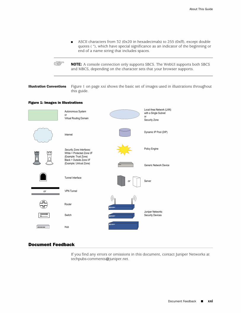
Illustration Conventions Figure 1 on page xxi shows the basic set of images used in illustrations throughoutthis guide.
Figure 1: Images in Illustrations
Document Feedback
If you find any errors or omissions in this document, contact Juniper Networks [email protected].
Document Feedback ■ xxi
About This Guide
Requesting Technical Support
Technical product support is available through the Juniper Networks TechnicalAssistance Center (JTAC). If you are a customer with an active J-Care or JNASC supportcontract, or are covered under warranty, and need postsales technical support, youcan access our tools and resources online or open a case with JTAC.
■ JTAC policies—For a complete understanding of our JTAC procedures and policies,review the JTAC User Guide located athttp://www.juniper.net/customers/support/downloads/710059.pdf.
■ Product warranties—For product warranty information, visithttp://www.juniper.net/support/warranty/.
■ JTAC hours of operation—The JTAC centers have resources available 24 hours aday, 7 days a week, 365 days a year.
Self-Help Online Toolsand Resources
For quick and easy problem resolution, Juniper Networks has designed an onlineself-service portal called the Customer Support Center (CSC) that provides you withthe following features:
■ Find CSC offerings—http://www.juniper.net/customers/support/
■ Search for known bugs—Find productdocumentation—http://www.juniper.net/techpubs/
■ Find solutions and answer questions using our Knowledge Base—http://kb.juniper.net/
■ Download the latest versions of software and review your release notes—http://www.juniper.net/customers/csc/software/
■ Search technical bulletins for relevant hardware and softwarenotifications—http://www.juniper.net/alerts/
■ Join and participate in the Juniper Networks Community Forum—http://www.juniper.net/company/communities/
■ Open a case online in the CSC Case Manager—http://www.juniper.net/customers/cm/
■ To verify service entitlement by product serial number, use our Serial NumberEntitlement (SNE) Tool—https://tools.juniper.net/SerialNumberEntitlementSearch/
Opening a Case withJTAC
You can open a case with JTAC on the Web or by telephone.
■ Use the Case Manager tool in the CSC at http://www.juniper.net/customers/cm/.
■ Call 1-888-314-JTAC (1-888-314-5822—toll free in USA, Canada, and Mexico).
For international or direct-dial options in countries without toll-free numbers, visitus at http://www.juniper.net/customers/support/requesting-support/.
xxii ■ Requesting Technical Support
Administration

Part 1
Administration
■ Administration on page 3
■ Monitoring Security Devices on page 65
Administration ■ 1

2 ■ Administration
Administration
Chapter 1
Administration
This chapter describes management methods and tools, methods for securingadministrative traffic, and the administrative privilege levels that you can assign toadmin users. This chapter contains the following sections:
■ Federal Information Processing Standards (FIPS) on page 3
■ Management with the Web User Interface on page 6
■ Management with the Command Line Interface on page 13
■ Management with the Network and Security Manager on page 27
■ Controlling Administrative Traffic on page 33
■ Levels of Administration on page 39
■ Defining Admin Users on page 42
■ Securing Administrative Traffic on page 45
■ Password Policy on page 60
■ Creating a Login Banner on page 62
Federal Information Processing Standards (FIPS)
Federal Information Processing Standards (FIPS) specify the security requirementsthat a cryptographic module employed within a security system should comply with.FIPS requires that the system provide a self-test function for cryptographic algorithmsat power on and conditional test. Juniper Networks security devices comply withFIPS by supporting this self-test on power-on.
Juniper Networks security devices support the self-test functions for the followingsituations:
■ At power on
■ On demand
■ After key generation
■ For periodic self-tests
Table 1 on page 4 lists the algorithms that the system tests as part of the FIPSrequirements.
Federal Information Processing Standards (FIPS) ■ 3
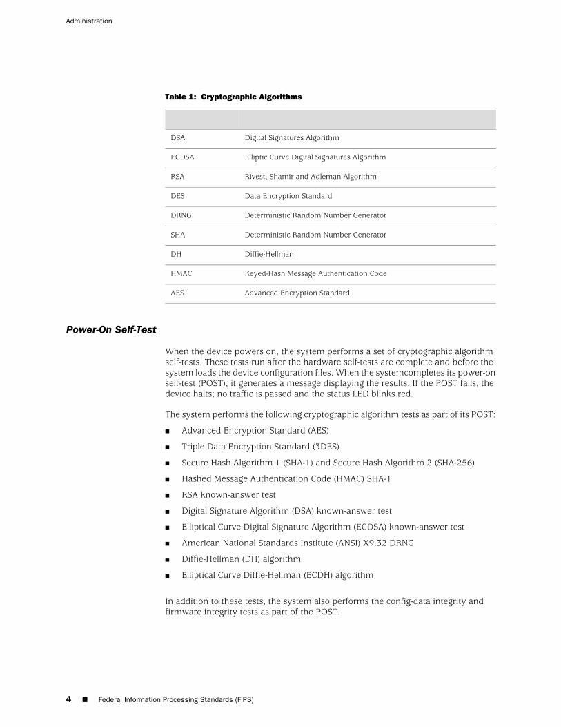
Table 1: Cryptographic Algorithms
Digital Signatures AlgorithmDSA
Elliptic Curve Digital Signatures AlgorithmECDSA
Rivest, Shamir and Adleman AlgorithmRSA
Data Encryption StandardDES
Deterministic Random Number GeneratorDRNG
Deterministic Random Number GeneratorSHA
Diffie-HellmanDH
Keyed-Hash Message Authentication CodeHMAC
Advanced Encryption StandardAES
Power-On Self-Test
When the device powers on, the system performs a set of cryptographic algorithmself-tests. These tests run after the hardware self-tests are complete and before thesystem loads the device configuration files. When the systemcompletes its power-onself-test (POST), it generates a message displaying the results. If the POST fails, thedevice halts; no traffic is passed and the status LED blinks red.
The system performs the following cryptographic algorithm tests as part of its POST:
■ Advanced Encryption Standard (AES)
■ Triple Data Encryption Standard (3DES)
■ Secure Hash Algorithm 1 (SHA-1) and Secure Hash Algorithm 2 (SHA-256)
■ Hashed Message Authentication Code (HMAC) SHA-1
■ RSA known-answer test
■ Digital Signature Algorithm (DSA) known-answer test
■ Elliptical Curve Digital Signature Algorithm (ECDSA) known-answer test
■ American National Standards Institute (ANSI) X9.32 DRNG
■ Diffie-Hellman (DH) algorithm
■ Elliptical Curve Diffie-Hellman (ECDH) algorithm
In addition to these tests, the system also performs the config-data integrity andfirmware integrity tests as part of the POST.
4 ■ Federal Information Processing Standards (FIPS)
Administration

Config-Data Integrity Test
In a config-data integrity test, the system calculates the SHA1 value for theconfiguration data and writes it in a new file. Whenever the system executes theconfig-data integrity test, it recalculates the hash value based on the configurationdata and compares it with the hash value stored in the new file. If both values arethe same, the device passes the config-data test.
Similarly, the system calculates the checksum of the public key infrastructure (PKI)database and stores it in flash memory. Whenever the PKI data changes, thechecksum is recalculated and stored in the flash. When the config-data integrity testis executed, the system recalculates the checksum using the latest PKI database andcompares it with the checksum stored in flash memory. If both checksums match,the PKI database is uncorrupted.
Firmware Integrity Test
Whenever the system administrator downloads the image using the save softwarecommand or through the boot loader, the system verifies the digital signature of theimage against the original digital image that was signed using DSA. If the verificationfails, the system does not write the image to the flash.
In the current release, you can configure a default gateway to download a boot loaderor a new image from a TFTP server when upgrading using the boot loader method.After initialization, the boot loader prompts you to provide an input. To upgrade theboot loader from the TFTP server, press the X and A keys simultaneously. You canhit any key for downloading a new image from the TFTP server. For the boot loaderto start the TFTP process, you should specify the IP address of your device, the maskof the subnet, the gateway to be used, and the IP address of your TFTP server. If thedevice address and the TFTP server address are not in the same subnet segment,the boot loader uses the specified gateway to initiate the TFTP process.
Self-Test on Demand by Administrator
The administrator can invoke the FIPS self-test at run time with the exec fips-modeself-test command. The cryptographic algorithms that are tested are similar to thosetested at self-test on power up. In addition to those tests, the system also performsthe config-data and firmware integrity tests as part of the self-test on demand. If thedevice fails the self-test, the system sends an error message to the console and thebuffer and stores it in the event log. If the periodic self-test is running when theadministrator invokes the self-test on demand, the system prompts the admin to tryagain later.
Any audit, cryptographic, or security administrator can execute the self-test ondemand.
Self-Test After Key Generation
Administrators can configure the FIPS self-test to run immediately after the generationof a key by using the set fips-mode self-test afterkeygen command. This option is
Federal Information Processing Standards (FIPS) ■ 5
Chapter 1: Administration
available only for asymmetric cryptographic algorithms such as DSA, RSA, ECDSA,and ECDH. The system will run pair-wise consistency tests on these algorithms.
NOTE: Only cryptographic administrators can enable and disable the self-test afterkey generation feature.
Periodic Self-Test
Administrators can also configure the system to run periodic self-tests by using theset fips-mode self-test interval command. Administrators can set the run intervalfor these tests from 1 to 24 hours. The cryptographic algorithms run during periodicself-tests are the same as those run at POST. Additionally, the system also performsthe config-data and firmware integrity tests as part of the periodic self-test.
NOTE: Only security administrators can configure the periodic self-test feature.
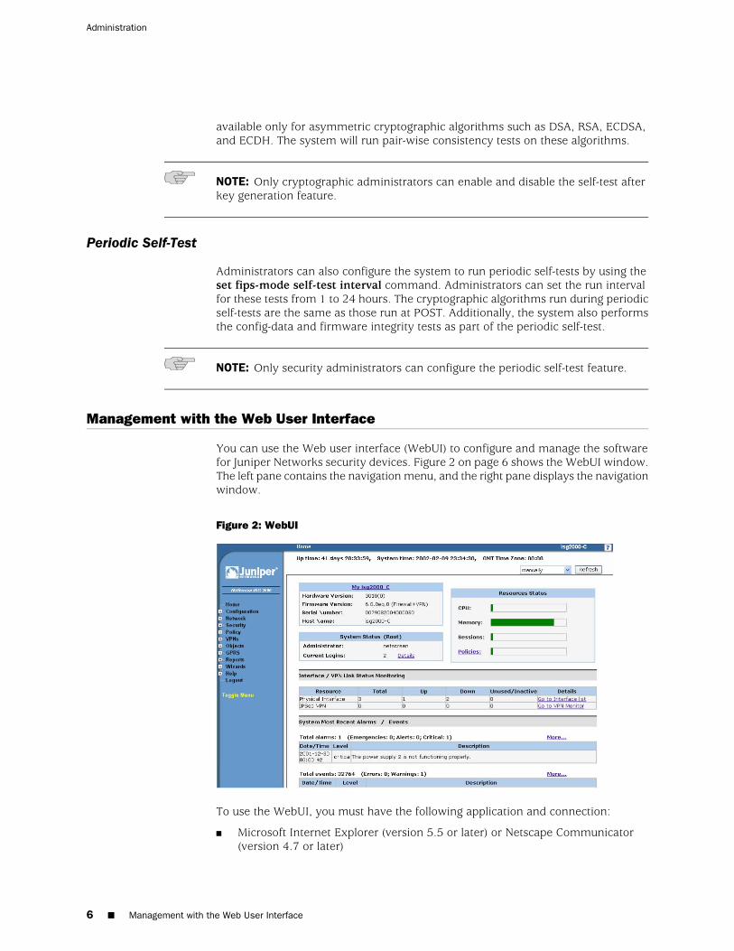
Management with the Web User Interface
You can use the Web user interface (WebUI) to configure and manage the softwarefor Juniper Networks security devices. Figure 2 on page 6 shows the WebUI window.The left pane contains the navigation menu, and the right pane displays the navigationwindow.
Figure 2: WebUI
To use the WebUI, you must have the following application and connection:
■ Microsoft Internet Explorer (version 5.5 or later) or Netscape Communicator(version 4.7 or later)
6 ■ Management with the Web User Interface
Administration
■ TCP/IP network connection to the security device
WebUI Help
You can view Help files for the WebUI athttp://help.juniper.net/help/english/screenos_version/filename.htm(for example, http://help.juniper.net/help/english/6.2.0/620_Help.htm).
You also have the option of relocating the Help files. You might want to store themlocally and point the WebUI to either the administrator’s workstation or a securedserver on the local network. In case you do not have Internet access, storing the Helpfiles locally provides accessibility to them you otherwise would not have.
Copying the Help Files to a Local Drive
The Help files are available on the documentation CD. You can modify the WebUIto point to the Help files on the CD in your local CD drive. You can also copy the filesfrom the CD to a server on your local network or to another drive on your workstationand configure the WebUI to invoke the Help files from that location.
NOTE: If you want to run the Help files directly from the documentation CD, youcan skip this procedure. Proceed to “Pointing the WebUI to the New Help Location”on page 7.
1. Load the documentation CD in the CD drive of your workstation.
2. Navigate to the CD drive and copy the directory named help.
3. Navigate to the location where you want to store the Help directory and pastethe Help directory there.
Pointing the WebUI to the New Help Location
You must now redirect the WebUI to point to the new location of the Help directory.Change the default URL to the new file path, where path is the specific path to theHelp directory from the administrator’s workstation.
1. Configuration > Admin > Management: In the Help Link Path field, replace thedefault URL:
http://help.juniper.net/help/english/screenos_version/filename.htm
with
(for local drive) file://path…/help
or
(for local server) http://server_name…/path/help
2. Click Apply.
Management with the Web User Interface ■ 7
Chapter 1: Administration
When you click the help link in the upper right corner of the WebUI, the devicenow uses the new path that you specified in the Help Link Path field to locatethe appropriate Help file.
HyperText Transfer Protocol
With a standard browser, you can access, monitor, and control your network securityconfigurations remotely using HyperText Transfer Protocol (HTTP).
You can secure HTTP administrative traffic by encapsulating it in a virtual privatenetwork (VPN) tunnel or by using the Secure Sockets Layer (SSL) protocol. You canfurther secure administrative traffic by completely separating it from network usertraffic. To do this, you can run all administrative traffic through the MGTinterface—available on some security devices—or bind an interface to the MGT zoneand devote it exclusively to administrative traffic.
NOTE: For more information, see “Secure Sockets Layer” on page 9, “MGT andVLAN1 Interfaces” on page 34, and “VPN Tunnels for Administrative Traffic” on page52.
Session ID
The security device assigns each HTTP administrative session a unique session ID.For security devices that support virtual systems (vsys), the ID is globally uniqueacross all systems—root and vsys.
Each session ID is a 39-byte number resulting from the combination of fivepseudo-randomly generated numbers. The randomness of the ID generation—versusa simple numerical incremental scheme—makes the ID nearly impossible to predict.Furthermore, the randomness combined with the length of the ID makes accidentalduplication of the same ID for two concurrent administrative sessions extremelyunlikely.
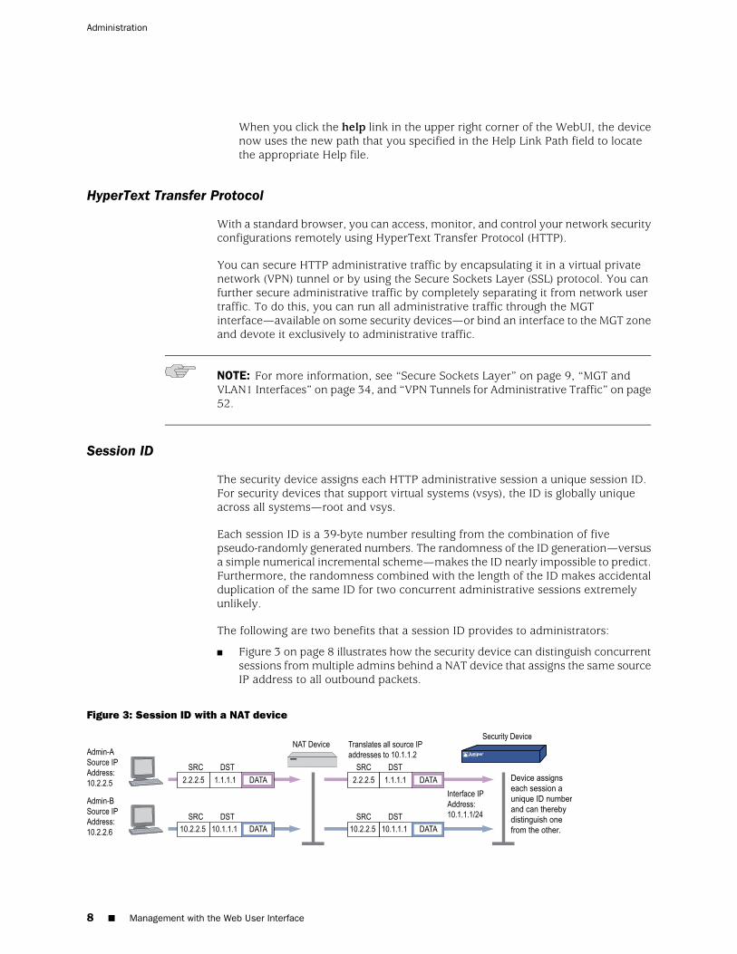
The following are two benefits that a session ID provides to administrators:
■ Figure 3 on page 8 illustrates how the security device can distinguish concurrentsessions from multiple admins behind a NAT device that assigns the same sourceIP address to all outbound packets.
Figure 3: Session ID with a NAT device
8 ■ Management with the Web User Interface
Administration
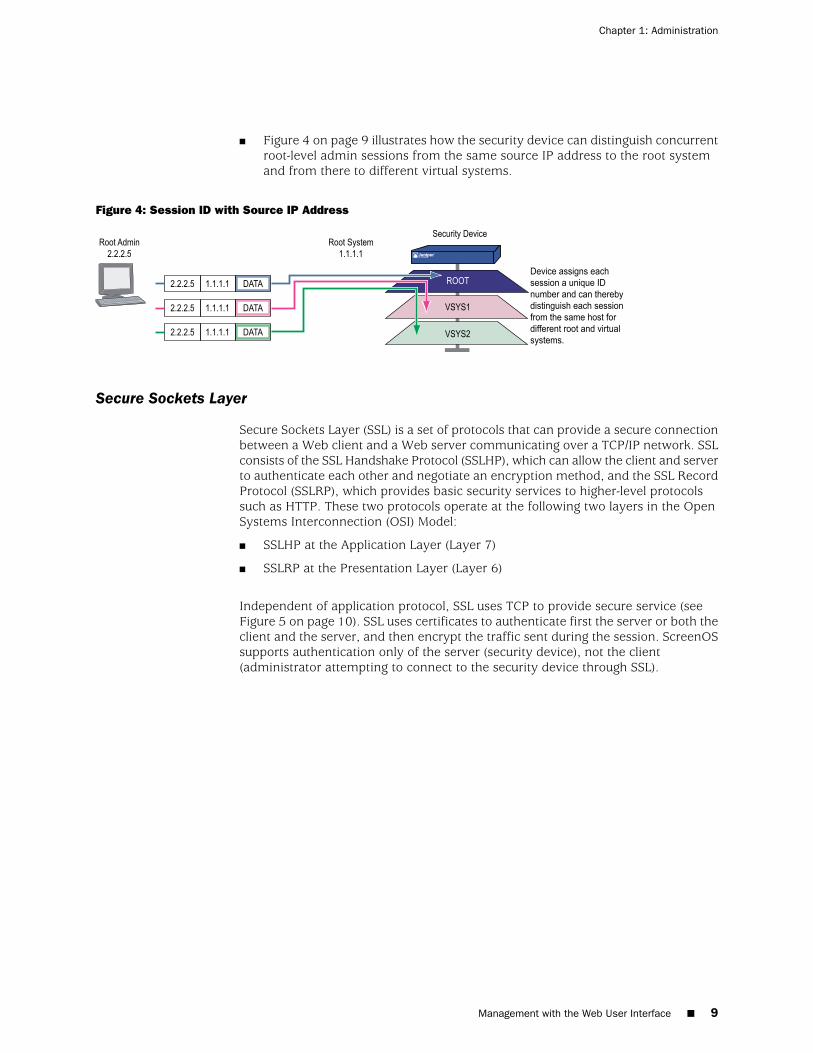
■ Figure 4 on page 9 illustrates how the security device can distinguish concurrentroot-level admin sessions from the same source IP address to the root systemand from there to different virtual systems.
Figure 4: Session ID with Source IP Address
Secure Sockets Layer
Secure Sockets Layer (SSL) is a set of protocols that can provide a secure connectionbetween a Web client and a Web server communicating over a TCP/IP network. SSLconsists of the SSL Handshake Protocol (SSLHP), which can allow the client and serverto authenticate each other and negotiate an encryption method, and the SSL RecordProtocol (SSLRP), which provides basic security services to higher-level protocolssuch as HTTP. These two protocols operate at the following two layers in the OpenSystems Interconnection (OSI) Model:
■ SSLHP at the Application Layer (Layer 7)
■ SSLRP at the Presentation Layer (Layer 6)
Independent of application protocol, SSL uses TCP to provide secure service (seeFigure 5 on page 10). SSL uses certificates to authenticate first the server or both theclient and the server, and then encrypt the traffic sent during the session. ScreenOSsupports authentication only of the server (security device), not the client(administrator attempting to connect to the security device through SSL).
Management with the Web User Interface ■ 9
Chapter 1: Administration
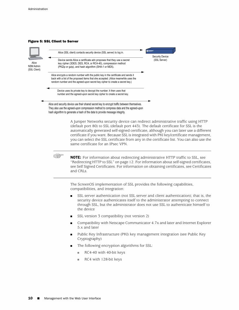
Figure 5: SSL Client to Server
A Juniper Networks security device can redirect administrative traffic using HTTP(default port 80) to SSL (default port 443). The default certificate for SSL is theautomatically generated self-signed certificate, although you can later use a differentcertificate if you want. Because SSL is integrated with PKI key/certificate management,you can select the SSL certificate from any in the certificate list. You can also use thesame certificate for an IPsec VPN.
NOTE: For information about redirecting administrative HTTP traffic to SSL, see“Redirecting HTTP to SSL” on page 12. For information about self-signed certificates,see Self Signed Certificates. For information on obtaining certificates, see Certificatesand CRLs.
The ScreenOS implementation of SSL provides the following capabilities,compatibilities, and integration:
■ SSL server authentication (not SSL server and client authentication); that is, thesecurity device authenticates itself to the administrator attempting to connectthrough SSL, but the administrator does not use SSL to authenticate himself tothe device
■ SSL version 3 compatibility (not version 2)
■ Compatibility with Netscape Communicator 4.7x and later and Internet Explorer5.x and later
■ Public Key Infrastructure (PKI) key management integration (see Public KeyCryptography)
■ The following encryption algorithms for SSL:
■ RC4-40 with 40-bit keys
■ RC4 with 128-bit keys
10 ■ Management with the Web User Interface
Administration
■ DES: Data Encryption Standard with 56-bit keys
■ 3DES: Triple DES with 168-bit keys
■ The same authentication algorithms for SSL as for VPNs:
■ Message Digest version 5 (MD5)—128-bit keys
■ Secure Hash Algorithm version 1 (SHA-1)—160-bit keys
■ Secure Hash Algorithm version 2 (SHA-2)—256-bit keys
NOTE: The RC4 algorithms are always paired with MD5; DES and 3DES are alwayspaired with SHA-1.
SSL Configuration
The basic steps for setting up SSL are as follows:
1. Make use of the self-signed certificate that the security device automaticallygenerates during its initial bootup, or create another self-signed certificate, orobtain a CA-signed certificate and load it on the device.
NOTE: Check your browser to see how strong the ciphers can be and which onesyour browser supports. (Both the security device and your browser must support thesame kind and size of ciphers you use for SSL.) In Internet Explorer 5x, click Help,About Internet Explorer, and read the section about cipher strength. To obtain theadvanced security package, click Update Information. In Netscape Communicator,click Help, About Communicator, and read the section about RSA. To change theSSL configuration settings, click Security Info, Navigator, Configure SSL v3.For more information, see Self Signed Certificates. For details on requesting andloading a certificate, see Certificates and CRLs.
2. Enable SSL management.
NOTE: SSL is enabled by default.
WebUI
Configuration > Admin > Management: Enter the following, then click Apply:
SSL: (select)Port: Use the default port number (443) or change it to another.Certificate: Select the certificate you intend to use from the drop-down list.Cipher: Select the cipher you intend to use from the drop-down list.
Management with the Web User Interface ■ 11
Chapter 1: Administration
NOTE: If you change the SSL port number, the admins need to specify the nondefaultport number when entering the URL in their browser.
CLI
set ssl port numset ssl cert id_numset ssl encrypt { { 3des | des } sha-1 | { rc4 | rc4-40 } | md5 }set ssl enablesave
NOTE: To learn the ID number for a certificate, use the following command:get pki x509 list cert.
3. Configure the interface through which you manage the security device to permitSSL management:
WebUI
Network > Interfaces > Edit (for the interface you want to manage): Select the SSLmanagement service check box, then click OK.
CLI
set interface interface manage sslsave
1. Connect to the security device through the SSL port. When you enter the IPaddress for managing the security device in the browser’s URL field, change httpto https, and follow the IP address with a colon and the HTTPS (SSL) port numberif you have changed it from the default. For example:
https://123.45.67.89:1443).
Redirecting HTTP to SSL
The security device can redirect administrative traffic using HTTP (default port 80)to SSL (default port 443), as shown in Figure 6 on page 13.
During the SSL handshake, the security device sends Alice its certificate. Alice encryptsa random number with the public key contained in the certificate and sends it backto the device, which uses its private key to decrypt the number. Both participantsthen use the shared random number and a negotiated secret key cipher (3DES, DES,RC4, or RC4-40) to create a shared secret key, which they use to encrypt trafficbetween themselves. They also use an agreed-upon compression method (PKZip orgzip) to compress data and an agreed-upon hash algorithm (SHA-1 or MD-5) togenerate a hash of the data to provide message integrity.
12 ■ Management with the Web User Interface
Administration
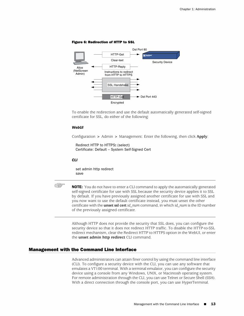
Figure 6: Redirection of HTTP to SSL
Alice(NetScreen
Admin)Instructions to redirectfrom HTTP to HTTPS
Dst Port 80
HTTP-Get
HTTP-Get
HTTP-Reply
Dst Port 443
Encrypted
SSL Handshake
Security DeviceClear-text
To enable the redirection and use the default automatically generated self-signedcertificate for SSL, do either of the following:
WebUI
Configuration > Admin > Management: Enter the following, then click Apply:
Redirect HTTP to HTTPS: (select)Certificate: Default – System Self-Signed Cert
CLI
set admin http redirectsave
NOTE: You do not have to enter a CLI command to apply the automatically generatedself-signed certificate for use with SSL because the security device applies it to SSLby default. If you have previously assigned another certificate for use with SSL andyou now want to use the default certificate instead, you must unset the othercertificate with the unset ssl cert id_num command, in which id_num is the ID numberof the previously assigned certificate.
Although HTTP does not provide the security that SSL does, you can configure thesecurity device so that it does not redirect HTTP traffic. To disable the HTTP-to-SSLredirect mechanism, clear the Redirect HTTP to HTTPS option in the WebUI, or enterthe unset admin http redirect CLI command.
Management with the Command Line Interface
Advanced administrators can attain finer control by using the command line interface(CLI). To configure a security device with the CLI, you can use any software thatemulates a VT100 terminal. With a terminal emulator, you can configure the securitydevice using a console from any Windows, UNIX, or Macintosh operating system.For remote administration through the CLI, you can use Telnet or Secure Shell (SSH).With a direct connection through the console port, you can use HyperTerminal.
Management with the Command Line Interface ■ 13
Chapter 1: Administration
NOTE: For a complete listing of the ScreenOS CLI commands, see the ScreenOS CLIReference Guide: IPv4 Command Descriptions.
Telnet
Telnet is a login and terminal emulation protocol that uses a client/server relationshipto connect to and remotely configure network devices over a TCP/IP network. Youcan create a connection with the Telnet client program on the security device bylaunching a Telnet server program on the admin workstation or other security device.After logging in, the administrator can issue CLI commands, which are sent to theTelnet program on the security device, effectively configuring the device as if operatingthrough a direct connection. Using Telnet to manage security devices requires thefollowing application and connection:
■ Telnet software on the admin workstation or other security device
■ Ethernet connection to the security device
NOTE: The Telnet client program is not available at the vsys level.
If you want to remotely check service availability using a telnet client, we recommendthat you connect to a Juniper Networks security device using Telnet/SSH rather thanconsole
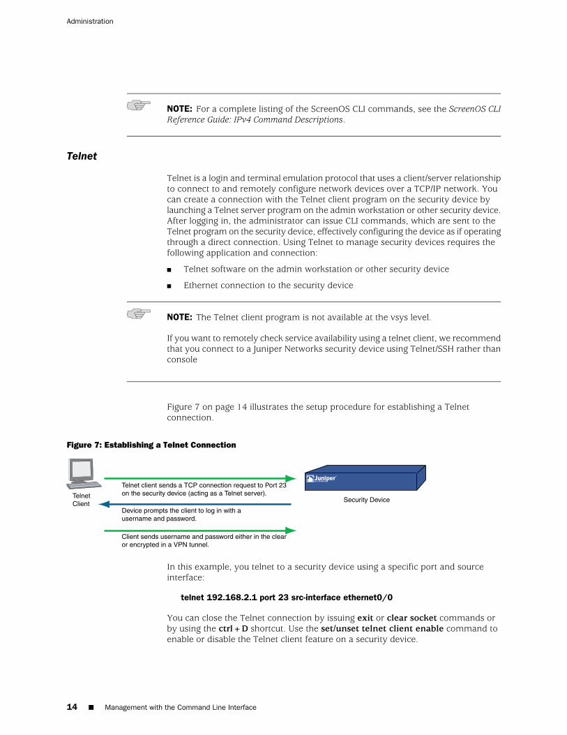
Figure 7 on page 14 illustrates the setup procedure for establishing a Telnetconnection.
Figure 7: Establishing a Telnet Connection
Telnet client sends a TCP connection request to Port 23on the security device (acting as a Telnet server).
Device prompts the client to log in with ausername and password.
Client sends username and password either in the clearor encrypted in a VPN tunnel.
TelnetClient
Security Device
In this example, you telnet to a security device using a specific port and sourceinterface:
telnet 192.168.2.1 port 23 src-interface ethernet0/0
You can close the Telnet connection by issuing exit or clear socket commands orby using the ctrl+D shortcut. Use the set/unset telnet client enable command toenable or disable the Telnet client feature on a security device.
14 ■ Management with the Command Line Interface
Administration
To minimize an unauthorized user’s chances of logging into a device, you can limitthe number of unsuccessful login attempts allowed before the security deviceterminates a Telnet session. This restriction also protects against certain types ofattacks, such as automated dictionary attacks.
By default, the device allows up to three unsuccessful login attempts before it closesthe Telnet session. To change this number, enter the following command:
set admin access attempts number
NOTE: You must use the CLI to set this restriction.
Securing Telnet Connections
You can secure Telnet traffic by completely separating it from network user traffic.Depending upon your security device model, you can run all administrative trafficthrough the MGT interface or devote an interface such as the DMZ entirely toadministrative traffic.
In addition, to ensure that admin users use a secure connection when they managea security device through Telnet, you can require such users to Telnet only througha virtual private network (VPN) tunnel. After you have set this restriction, the devicedenies access if anyone tries to Telnet without going through a VPN tunnel.
NOTE: For information about VPN tunnels, see Virtual Private Networks.
To restrict Telnet access through a VPN:
set admin telnet access tunnel
NOTE: You must use the CLI to set this restriction.
Secure Shell
The built-in Secure Shell (SSH) server on a Juniper Networks security device providesa means by which administrators can remotely and securely manage the device inusing applications that are SSH-aware. SSH allows you to open a remote commandshell securely and execute commands. SSH provides protection from IP or DNSspoofing attacks and password or data interception.
You can choose to run either an SSH version 1 (SSHv1) or an SSH version 2 (SSHv2)server on the device. SSHv2 is considered more secure than SSHv1 and is currentlybeing developed as the IETF standard. However, SSHv1 has been widely deployedand is commonly used. Note that SSHv1 and SSHv2 are not compatible. That is, youcannot use an SSHv1 client to connect to an SSHv2 server on the security device andyou cannot use an SSHv2 client to connect to an SSHv1 server on the security device.
Management with the Command Line Interface ■ 15
Chapter 1: Administration
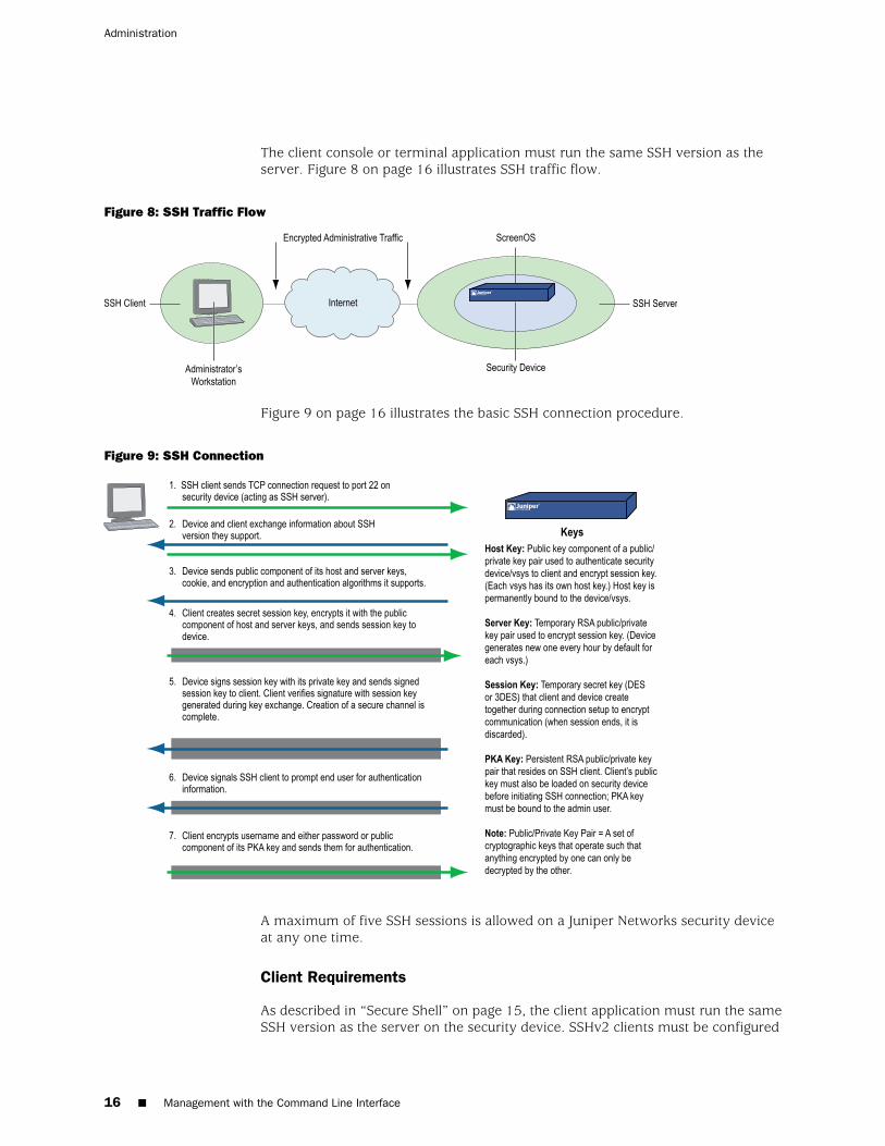
The client console or terminal application must run the same SSH version as theserver. Figure 8 on page 16 illustrates SSH traffic flow.
Figure 8: SSH Traffic Flow
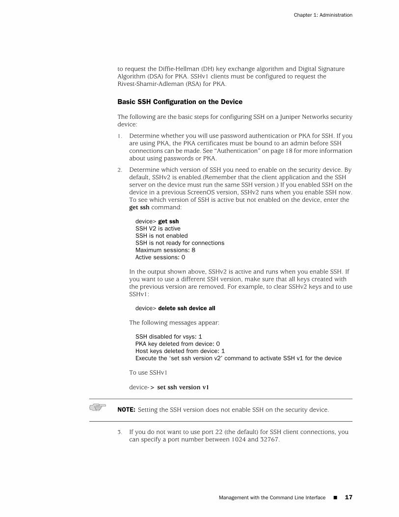
Figure 9 on page 16 illustrates the basic SSH connection procedure.
Figure 9: SSH Connection
A maximum of five SSH sessions is allowed on a Juniper Networks security deviceat any one time.
Client Requirements
As described in “Secure Shell” on page 15, the client application must run the sameSSH version as the server on the security device. SSHv2 clients must be configured
16 ■ Management with the Command Line Interface
Administration
to request the Diffie-Hellman (DH) key exchange algorithm and Digital SignatureAlgorithm (DSA) for PKA. SSHv1 clients must be configured to request theRivest-Shamir-Adleman (RSA) for PKA.
Basic SSH Configuration on the Device
The following are the basic steps for configuring SSH on a Juniper Networks securitydevice:
1. Determine whether you will use password authentication or PKA for SSH. If youare using PKA, the PKA certificates must be bound to an admin before SSHconnections can be made. See “Authentication” on page 18 for more informationabout using passwords or PKA.
2. Determine which version of SSH you need to enable on the security device. Bydefault, SSHv2 is enabled.(Remember that the client application and the SSHserver on the device must run the same SSH version.) If you enabled SSH on thedevice in a previous ScreenOS version, SSHv2 runs when you enable SSH now.To see which version of SSH is active but not enabled on the device, enter theget ssh command:
device> get sshSSH V2 is activeSSH is not enabledSSH is not ready for connectionsMaximum sessions: 8Active sessions: 0
In the output shown above, SSHv2 is active and runs when you enable SSH. Ifyou want to use a different SSH version, make sure that all keys created withthe previous version are removed. For example, to clear SSHv2 keys and to useSSHv1:
device> delete ssh device all
The following messages appear:
SSH disabled for vsys: 1PKA key deleted from device: 0Host keys deleted from device: 1Execute the ‘set ssh version v2’ command to activate SSH v1 for the device
To use SSHv1
device-> set ssh version v1
NOTE: Setting the SSH version does not enable SSH on the security device.
3. If you do not want to use port 22 (the default) for SSH client connections, youcan specify a port number between 1024 and 32767.
Management with the Command Line Interface ■ 17
Chapter 1: Administration
NOTE: You can also use the WebUI to change the port number and enable SSHv2and SCP on the Configuration > Admin > Management page.
device-> set admin ssh port 1024
4. Enable SSH for the root system or for the virtual system. See “SSH and Vsys” onpage 20 for additional information about enabling and using SSH for a vsys.
To enable SSH for the root system:
device-> set ssh enable
To enable SSH for a vsys, you need to first enter the vsys and then enable SSH:
device-> set vsys v1device(v1)-> set ssh enable
5. Enable SSH on the interface on which the SSH client will connect.
device-> set interface manage ssh
6. Distribute the host certificate to the SSH client. See “Host Certificate” on page22 for more information.
Authentication
An administrator can connect to a Juniper Networks security device with SSH usingone of two authentication methods:
■ Password Authentication: This method is used by administrators who need toconfigure or monitor a security device. The SSH client initiates an SSH connectionto the device. If SSH manageability is enabled on the interface receiving theconnection request, the device signals the SSH client to prompt the user for ausername and password. When the SSH client has this information, it sends itto the device, which compares it with the username and password in the adminuser’s account. If they match, the device authenticates the user. If they do notmatch, the device rejects the connection request.
■ Public Key Authentication with key (PKA key): This method provides increasedsecurity over the password authentication method and allows you to runautomated scripts. Instead of a username and password, the SSH client sends ausername and the public key component of a public/private key pair. The devicecompares it with up to four public keys that can be bound to an admin. If oneof the keys matches, the device authenticates the user. If none of them matches,the device rejects the connection request.
■ Public Key Authentication with certificate (PKA certificate): This method isvery similar to PKA with key, but instead of using raw keys, PKI certificates areused. The public key is embedded in the PKI certificate. This method requiresthat the certificate be loaded to the security device and then bound to anadministrators account. This method provides increased security over PKA withkeys in that the certificate contains the information identify the owner of the
18 ■ Management with the Command Line Interface
Administration

certificate and the identity of the CA that has verified the identity. Thisauthentication method is supported by SSHv2 only.
NOTE: The supported authentication algorithms are RSA for SSHv1 and DSA forSSHv2.
Both authentication methods require the establishment of a secure connection beforethe SSH client logs in. After an SSH client has established an SSH connection withthe device, he must authenticate himself either with a username and password orwith a PKA certificate.
Both password authentication and PKA require that you create an account for theadmin user on the device and enable SSH manageability on the interface throughwhich you intend to manage the device with an SSH connection. (For informationabout creating an admin user account, see “Defining Admin Users” on page 42.) Thepassword authentication method does not require any further set up on the SSHclient.
Binding a PKA key to administrator
To prepare for PKA, you must first perform the following tasks:
1. On the SSH client, generate a public and private key pair using a key generationprogram. (The key pair is either RSA for SSHv1 or DSA for SSHv2. See the SSHclient application documentation for more information.)
NOTE: If you want to use PKA for automated logins, you must also load an agent onthe SSH client to decrypt the private key component of the PKA public/private keypair and hold the decrypted version of the private key in memory.
2. Move the public key from the local SSH directory to a directory on your TFTPserver, and launch the TFTP program.
3. To load the public key from the TFTP server to the device, enter one of thefollowing CLI commands:
For SSHv1:
exec ssh tftp pka-rsa [ username name ] file-name name_str ip-addr tftp_ip_addr
For SSHv2:
exec ssh tftp pka-dsa [ user-name name ] file-name name_str ip-addr tftp_ip_addr
4. Bind the PKA key, a public key to the administrative account of the administratorthat who processes the associated private key. The following CLI commands canbe used to bind the PKA key to an administrators account:
set ssh pka-dsa key pka-keyset ssh pka-dsa user-name login-id key pka-key
Management with the Command Line Interface ■ 19
Chapter 1: Administration
The user-name option is only available to the root admin, so that only the rootadmin can bind to another admin. When you—as the root admin or as aread/write admin—enter the command without a username, the device bindsthe PKA certificate to your own admin account; that is, it binds the certificate tothe admin who enters the command.
NOTE: The security device supports up to four PKA public keys per admin user.
When an administrator attempts to log in via SSH on an interface that has SSHmanageability enabled, the device first checks if a public key is bound to thatadministrator. If so, the device authenticates the administrator using PKA. If a publickey is not bound to the administrator, the device prompts for a username andpassword. (You can use the following command to force an admin to use only thePKA method: set admin ssh password disable username name_str.) Regardless ofthe authentication method you intend the administrator to use, when you initiallydefine his or her account, you still must include a password, even though when youlater bind a public key to this user, the password becomes irrelevant.
Binding a PKA certificate to administrator
1. Using the SSH client or a key generation utility generate a public key pair.
2. Using certificate request utility generate a certificate request with the public keypair embedded.
3. Submit the certificate request to a CA to generate a certificate.
4. Store the PKA certificate in the security devices PKI DB. The PKI system willassign a unique key-id to the certificate.
5. To bind the PKA certificate to an administrative account use the followingcommands:
set ssh pka-dsa cert cert-idset ssh pka-dsa user-name login-id cert-id cert-id
The user-name option is only available to the ROOT privileged admin, since only theROOT privileged admin is permitted to bind PKA certificates to the accounts belongingto other administrators will a non-ROOT privileged level. When no login-id is specified,the PKA certificate is bound to the account of the administrator executing thecommand.
NOTE: The security device supports up to four PKA public certificates per administrator
SSH and Vsys
For security devices that support vsys, you can enable and configure SSH for eachvsys. SSH uses Host Keys or Host Certificates to provide a means to identify a server
20 ■ Management with the Command Line Interface
Administration

side entity to the SSH client. Each device has its own host key (see “Host Key” onpage 21) and maintains and manages a PKA key for the admin of the system.
In the case of Host Certificates (see “Host Certificate” on page 22), a single HostCertificate is used to identity the root system and all VSYS. This single Host Certificatemust first be created and explicitly bound to the security devices SSH server/device.
The maximum number of SSH sessions is a device-wide limit and is between 2 and24, depending upon the device. If the maximum number of SSH clients are alreadylogged into the device, no other SSH client can log into the SSH server. The rootsystem and the vsys share the same SSH port number. This means that if you changethe SSH port from the default port 22, the port is changed for all vsys as well.
NOTE: When you deploy a large number of virtual systems on a single device, beaware that if many or all vsys admins use SSH, the storage reserved for PKI objectscan fill up.
Host Key
The host key allows the security device to identify itself to an SSH client. On devicesthat support virtual systems (vsys), each vsys has its own host key. When SSH is firstenabled on a vsys (for devices that support vsys) or on a device, a host key isgenerated that is unique to the vsys or device. The host key is permanently boundto the vsys or device and the same host key is used if SSH is disabled and thenenabled again.
The host key on the device must be distributed to the SSH client in one of two ways:
■ Manually—the root or vsys admin sends the host key to the client admin userwith email, telephone, and so on. The receiving admin stores the host key in theappropriate SSH file on the SSH client system. (The SSH client applicationdetermines the file location and format.)
■ Automatically—When the SSH client connects to the device, the SSH server sendsthe unencrypted public component of the host key to the client. The SSH clientsearches its local host key database to see if the received host key is mapped tothe address of the device. If the host key is unknown (there is no mapping tothe device address in the client’s host key database), the Admin user might beable to decide whether to accept the host key. Otherwise, the connection isterminated. (See the appropriate SSH client documentation for information onaccepting unknown host keys.)
To verify that the SSH client has received the correct host key, the Admin user onthe client system can generate the SHA hash of the received host key. The clientAdmin user can then compare this SHA hash with the SHA hash of the host key onthe device. On the device, you can display the SHA hash of the host key by executingthe CLI command get ssh host-key.
Management with the Command Line Interface ■ 21
Chapter 1: Administration

Host Certificate
The host certificate allows the device to identify itself on the SSH client application.The SSH client application loads a local certificate to the device with the subject namessh-cert-dsa along with the related CA certificate and CRL. The security device assignsa certificate ID to each host certificate and stores it in the PKI database.
Before binding the host certificate to the device, perform the following steps:
1. Disable SSH for all vsys and delete all host keys:
delete ssh device all
2. Set SSH version to the active version:
set ssh version 2
Once the certificate is loaded, the root-admin can force the device to use the hostcertificate by using the CLI command;
set ssh host-identity cert-dsa cert-id
where cert-id denotes the ID of the host certificate.
When the SSH client application connects to the device, the device sends the hostcertificate to the SSH client application. The application performs assured certificationof the device based on the host certificate.
To unbind the host certificate from the device use the delete ssh device all command.
Binding a Host certificate to a device is not permitted in the following situations:
■ No version of SSH is active
■ SSH version1 is active
■ SSH is enabled for any vsys
■ The host key is still bound to any VSYS.
■ The certificate-ID does not exist.
■ The host certificate has an invalid subject name.
Example: SSHv1 with PKA for Automated Logins
In this example, you (as the root admin) set up SSHv1 public key authentication(PKA) for a remote host that runs an automated script. The sole purpose for thisremote host to access the device is to download the configuration file every night.Because authentication is automated, no human intervention is necessary when theSSH client logs into the device.
22 ■ Management with the Command Line Interface
Administration
You define an admin user account named cfg, with password cfg and read-writeprivileges. You enable SSH manageability on interface ethernet1, which is bound tothe Untrust zone.
You have previously used a key generation program on your SSH client to generatean RSA public/private key pair, moved the public key file, which has the filename“idnt_cfg.pub”, to a directory on your TFTP server, and launched the TFTP program.The IP address of the TFTP server is 10.1.1.5.
WebUI
Configuration > Admin > Administrators > New: Enter the following, then clickOK:
Name: cfgNew Password: cfgConfirm Password: cfgPrivileges: Read-Write (select)SSH Password Authentication: (select)
Network > Interfaces > Edit (for ethernet1): Select SSH in Service Options, thenclick OK.
NOTE: You can only load a public key file for SSH from a TFTP server with the execssh command.
CLI
set admin user cfg password cfg privilege allset interface ethernet1 manage sshexec ssh tftp pka-rsa username cfg file-name idnt_cfg.pub ip-addr 10.1.1.5save
Secure Copy
Secure Copy (SCP) provides a way for a remote client to transfer files to or from thesecurity device using the SSH protocol. (The SSH protocol provides authentication,encryption, and data integrity to the SCP connection.) The device acts as an SCPserver to accept connections from SCP clients on remote hosts.
SCP requires that the remote client be authenticated before file transfer commences.SCP authentication is exactly the same process used to authenticate SSH clients. TheSCP client can be authenticated with either a password or a PKA key. Once the SCPclient is authenticated, one or more files can be transferred to or from the device.The SCP client application determines the exact method for specifying the sourceand destination filenames; see the SCP client application documentation.
SCP is disabled by default on the device. To enable SCP, you must also enable SSH.
Management with the Command Line Interface ■ 23
Chapter 1: Administration
WebUI
Configuration > Admin > Management: Select the following, then click Apply:
Enable SSH: (select)Enable SCP: (select)
CLI
set ssh enableset scp enablesave
The following is an example of an SCP client command to copy the configurationfile from flash memory on a device (administrator name is “juniper” and the IPaddress is 10.1.1.1) to the file “ns_sys_config_backup” on the client system:
scp [email protected]:ns_sys_config ns_sys_config_backup
You can also copy a ScreenOS image to and from a device. To save an image named“ns.5.1.0r1” to a device from an SCP client, enter the following SCP client command,in which the administrator's login name is “juniper” and the IP address of the deviceis 10.1.1.1:
scp ns.5.1.0r1 [email protected]:image
Then enter the reset command to reboot the security device to load and run the newScreenOS image.
To copy a ScreenOS image from a device to an SCP client and name the saved image“current_image_backup,” enter the following SCP client command:
scp [email protected]:image current_image_backup
You need to consult your SCP client application documentation for information onhow to specify the administrator name, device IP address, source file, and destinationfile.
Serial Console
You can manage a security device through a direct serial connection from theadministrator’s workstation to the device with the console port. Although a directconnection is not always possible, this is the most secure method for managing thedevice provided that the location around the device is secure.
NOTE: To prevent unauthorized users from logging in remotely as the root admin,you can require the root admin to log into the device through the console only. Foradditional information on this restriction, see “Restricting the Root Admin to ConsoleAccess” on page 50.
24 ■ Management with the Command Line Interface
Administration
Depending on your Juniper Networks security device model, creating a serialconnection requires one of the following cables:
■ A female DB-9 to male DB-25 straight-through serial cable
■ A female DB-9 to male DB-9 straight-through serial cable
■ A female DB-9 to male MiniDIN-8 serial cable
■ A female DB-9 to RJ-45 adapter with an RJ-45 to RJ-45 straight-through Ethernetcable
You will also need HyperTerminal software (or another kind of VT100 terminalemulator) on the management workstation, with the HyperTerminal port settingsconfigured as follows:
■ Serial communications 9600 bps
■ 8 bit
■ No parity
■ 1 stop bit
■ No flow control
NOTE: For more details on using HyperTerminal, see the ScreenOS CLI ReferenceGuide: IPv4 Command Descriptions or the documentation for your device.
Remote Console
You can remotely access the console interface on a security device by dialing intoit. There are two ways of dialing into the console:
■ “Remote Console Using V.92 Modem Port” on page 25
■ “Remote Console Using an AUX Port” on page 26
Remote Console Using V.92 Modem Port
You can remotely manage the security devices that are equipped with v.92 modemports by dialing into the port and accessing the console interface. To use remoteconsole, you connect the v.92 modem port on the device to a telephone line, anddial into the device using a remote computer with a modem. You use a terminalprogram such as HyperTerminal to establish the console session.
In order to use remote console connection, you must first enable remote managementwith the following CLI command:
set interface serialx/0 modem auxenablesave
Figure 10 on page 26 shows how to connect the device for remote consolemanagement.
Management with the Command Line Interface ■ 25
Chapter 1: Administration
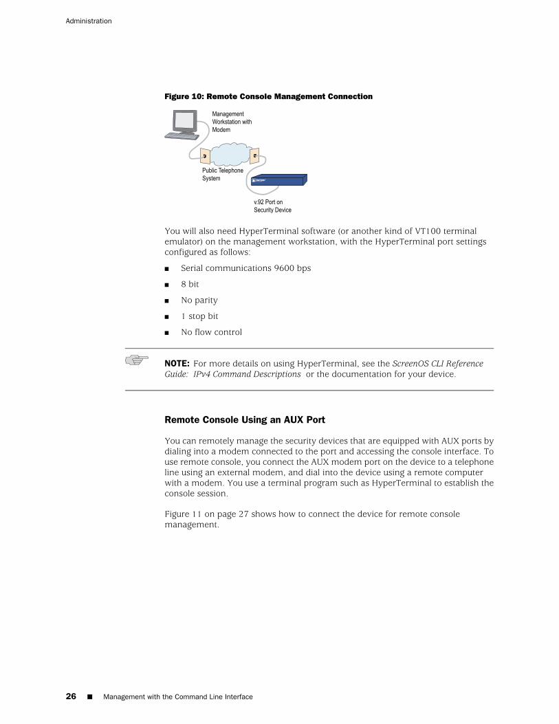
Figure 10: Remote Console Management Connection
You will also need HyperTerminal software (or another kind of VT100 terminalemulator) on the management workstation, with the HyperTerminal port settingsconfigured as follows:
■ Serial communications 9600 bps
■ 8 bit
■ No parity
■ 1 stop bit
■ No flow control
NOTE: For more details on using HyperTerminal, see the ScreenOS CLI ReferenceGuide: IPv4 Command Descriptions or the documentation for your device.
Remote Console Using an AUX Port
You can remotely manage the security devices that are equipped with AUX ports bydialing into a modem connected to the port and accessing the console interface. Touse remote console, you connect the AUX modem port on the device to a telephoneline using an external modem, and dial into the device using a remote computerwith a modem. You use a terminal program such as HyperTerminal to establish theconsole session.
Figure 11 on page 27 shows how to connect the device for remote consolemanagement.
26 ■ Management with the Command Line Interface
Administration
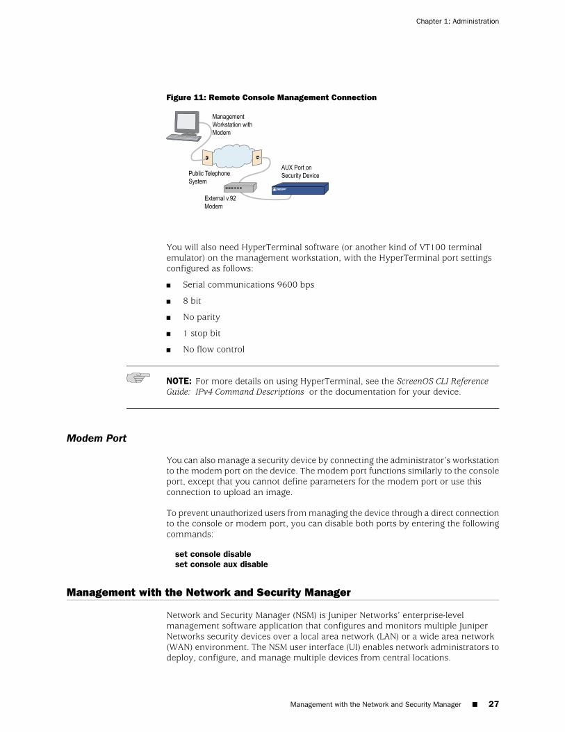
Figure 11: Remote Console Management Connection
You will also need HyperTerminal software (or another kind of VT100 terminalemulator) on the management workstation, with the HyperTerminal port settingsconfigured as follows:
■ Serial communications 9600 bps
■ 8 bit
■ No parity
■ 1 stop bit
■ No flow control
NOTE: For more details on using HyperTerminal, see the ScreenOS CLI ReferenceGuide: IPv4 Command Descriptions or the documentation for your device.
Modem Port
You can also manage a security device by connecting the administrator’s workstationto the modem port on the device. The modem port functions similarly to the consoleport, except that you cannot define parameters for the modem port or use thisconnection to upload an image.
To prevent unauthorized users from managing the device through a direct connectionto the console or modem port, you can disable both ports by entering the followingcommands:
set console disableset console aux disable
Management with the Network and Security Manager
Network and Security Manager (NSM) is Juniper Networks’ enterprise-levelmanagement software application that configures and monitors multiple JuniperNetworks security devices over a local area network (LAN) or a wide area network(WAN) environment. The NSM user interface (UI) enables network administrators todeploy, configure, and manage multiple devices from central locations.
Management with the Network and Security Manager ■ 27
Chapter 1: Administration
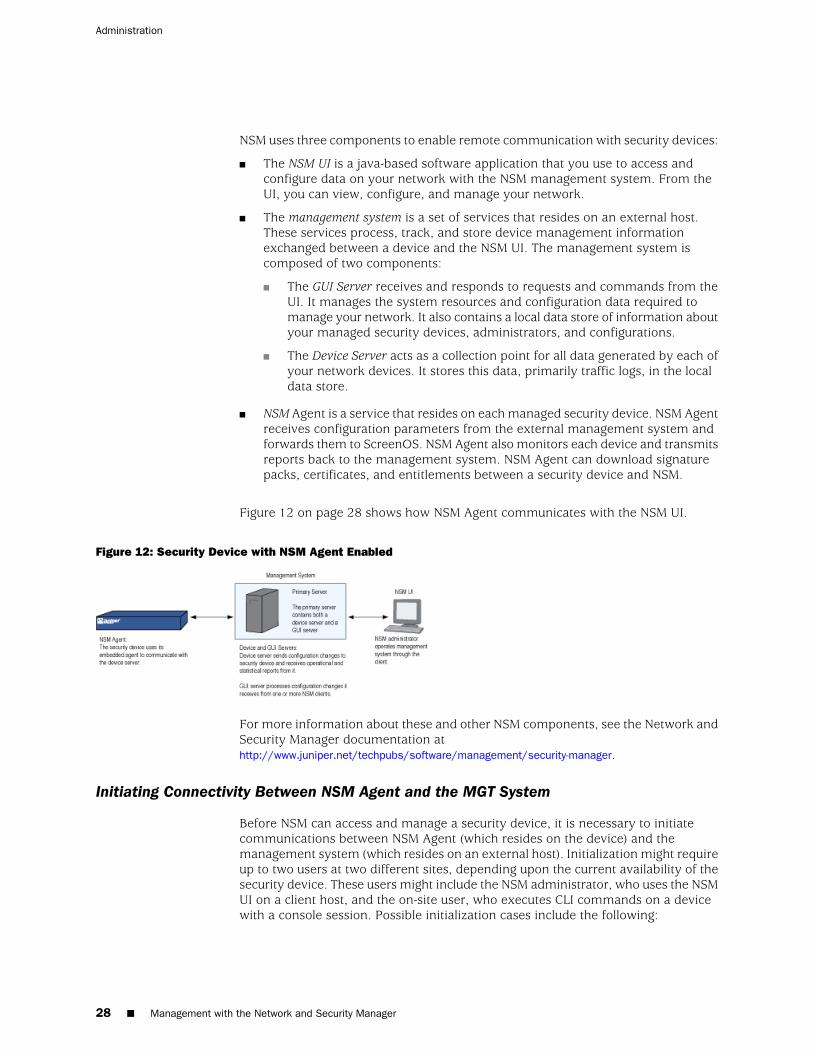
NSM uses three components to enable remote communication with security devices:
■ The NSM UI is a java-based software application that you use to access andconfigure data on your network with the NSM management system. From theUI, you can view, configure, and manage your network.
■ The management system is a set of services that resides on an external host.These services process, track, and store device management informationexchanged between a device and the NSM UI. The management system iscomposed of two components:
■ The GUI Server receives and responds to requests and commands from theUI. It manages the system resources and configuration data required tomanage your network. It also contains a local data store of information aboutyour managed security devices, administrators, and configurations.
■ The Device Server acts as a collection point for all data generated by each ofyour network devices. It stores this data, primarily traffic logs, in the localdata store.
■ NSM Agent is a service that resides on each managed security device. NSM Agentreceives configuration parameters from the external management system andforwards them to ScreenOS. NSM Agent also monitors each device and transmitsreports back to the management system. NSM Agent can download signaturepacks, certificates, and entitlements between a security device and NSM.
Figure 12 on page 28 shows how NSM Agent communicates with the NSM UI.
Figure 12: Security Device with NSM Agent Enabled
For more information about these and other NSM components, see the Network andSecurity Manager documentation athttp://www.juniper.net/techpubs/software/management/security-manager.
Initiating Connectivity Between NSM Agent and the MGT System
Before NSM can access and manage a security device, it is necessary to initiatecommunications between NSM Agent (which resides on the device) and themanagement system (which resides on an external host). Initialization might requireup to two users at two different sites, depending upon the current availability of thesecurity device. These users might include the NSM administrator, who uses the NSMUI on a client host, and the on-site user, who executes CLI commands on a devicewith a console session. Possible initialization cases include the following:
28 ■ Management with the Network and Security Manager
Administration
■ Case 1: A device already has a known IP address and is reachable over yournetwork infrastructure.
In this case, the NSM administrator adds the device using the NSM UI on theclient host. (No on-site user is necessary.) The device automatically connectsback to the management system and is ready to send configuration informationto the NSM database that resides there.
■ Case 2: The IP address is unreachable.
In this case, both users perform initialization tasks. The administrator adds thedevice through the NSM UI. The administrator also determines which CLIcommands the on-site user needs and delivers them to the user, who thenexecutes them through the console. The device then automatically connects withthe management system and is ready to send configuration information to theNSM database.
■ Case 3: The device is a new appliance and contains the factory default settings.
In this case, both users perform initialization tasks. The on-site user can use anencrypted configuration script, called a configlet, which the NSM administratorgenerates. The process is as follows:
1. The administrator selects the device platform and ScreenOS version, usingthe Add Device wizard in the NSM UI.
2. The administrator edits the device and enters the desired configuration.
3. The administrator activates the device.
4. The administrator generates and delivers the Configlet file (or the necessaryCLI commands, as with Case 2) to the on-site user.
5. The on-site user executes Configlet (or the CLI commands).
For more information, see the Network and Security Manager documentation athttp://www.juniper.net/techpubs/software/management/security-manager.
Enabling, Disabling, and Unsetting NSM Agent
Before a security device can communicate with the management system, you mustenable Network and Security Manager (NSM) Agent residing on the device.
If you want to unset NSM, use the unset nsmgmt all command. This command setsNSM Agent to its initial defaults, so it acts as though it was never connected to NSM.Use the unset nsmgmt all command when you want to reconfigure the NSM settings.
To enable NSM Agent on the security device, do either of the following:
WebUI
Configuration > Admin > NSM: Select Enable Communication with Network andSecurity Manager (NSM), then click Apply.
Management with the Network and Security Manager ■ 29
Chapter 1: Administration
CLI
set nsmgt enablesave
To disable NSM Agent on the device, do either of the following:
WebUI
Configuration > Admin > NSM: Clear Enable Communication with Network andSecurity Manager (NSM), then click Apply.
CLI
unset nsmgt enablesave
Setting the Primary Server IP Address of the Management System
The IP address by which NSM Agent identifies the external management systemservers is a configurable parameter.
In the following example you set the primary server IP address to 1.1.1.100.
WebUI
Configuration > Admin > NSM: Enter the following, then click Apply:
Primary IP Address/Name: 1.1.1.100
CLI
set nsmgmt server primary 1.1.1.100save
Setting Alarm and Statistics Reporting
NSM Agent monitors the device events and transmits reports back to the managementsystem. This allows the NSM administrator to view the events from the NSM UI.
The categories of events tracked by NSM Agent are as follows:
■ Alarms report potentially dangerous attacks or traffic anomalies, including attacksdetected through deep inspection.
■ Log events report changes in a device’s configuration and non-severe changesthat occur on a device.
■ Protocol distribution events report messages generated by the following protocols:
30 ■ Management with the Network and Security Manager
Administration
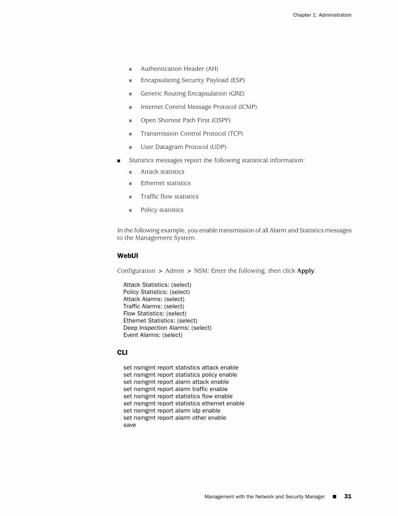
■ Authentication Header (AH)
■ Encapsulating Security Payload (ESP)
■ Generic Routing Encapsulation (GRE)
■ Internet Control Message Protocol (ICMP)
■ Open Shortest Path First (OSPF)
■ Transmission Control Protocol (TCP)
■ User Datagram Protocol (UDP)
■ Statistics messages report the following statistical information:
■ Attack statistics
■ Ethernet statistics
■ Traffic flow statistics
■ Policy statistics
In the following example, you enable transmission of all Alarm and Statistics messagesto the Management System.
WebUI
Configuration > Admin > NSM: Enter the following, then click Apply:
Attack Statistics: (select)Policy Statistics: (select)Attack Alarms: (select)Traffic Alarms: (select)Flow Statistics: (select)Ethernet Statistics: (select)Deep Inspection Alarms: (select)Event Alarms: (select)
CLI
set nsmgmt report statistics attack enableset nsmgmt report statistics policy enableset nsmgmt report alarm attack enableset nsmgmt report alarm traffic enableset nsmgmt report statistics flow enableset nsmgmt report statistics ethernet enableset nsmgmt report alarm idp enableset nsmgmt report alarm other enablesave
Management with the Network and Security Manager ■ 31
Chapter 1: Administration
Configuration Synchronization
If the ScreenOS configuration is changed from the last time it was synchronized withNSM, then the security device notifies the NSM administrator of the change. Forexample, the device sends a message when a device administrator uses console,telnet, SSH, or the WebUI to change a security device configuration. Changing theconfiguration with any application other than NSM causes it to be unsynchronized.The NSM configuration file must be synchronized with the security deviceconfiguration file for NSM to work correctly. The synchronization is achieved whenyou import the configuration file to NSM. For information about importing devices,see the Network and Security Manager documentation athttp://www.juniper.net/techpubs/software/management/security-manager,
The following example displays the command used to view the configuration status.
Example: Viewing the Configuration State
In the following example, you view the configuration synchronization state of asecurity device.
WebUI
NOTE: You must use the CLI to retrieve the running configuration state.
CLI
get config nsmgmt-dirty
NOTE: If applications other than NSM applications have not changed the configurationfile, then the command returns a blank; otherwise, it returns a “yes.”
Example: Retrieving the Configuration Hash
NSM uses the configuration hash to verify the configuration synchronization of asecurity device. In the following example, you retrieve the running configurationhash for a specific virtual system.
WebUI
NOTE: You must use the CLI to retrieve the running configuration hash.
CLI
device-> enter vsys vsys1
32 ■ Management with the Network and Security Manager
Administration
device(vsys1)-> get config hasha26a16cd6b8ef40dc79d5b2ec9e1ab4fdevice(vsys1)->device(vsys1)-> exit
Retrieving the Configuration Timestamp
A security device provides two configuration timestamps—running-config andsaved-config. The running-config timestamp is when the set or unset command waslast executed for each virtual system. The saved-config timestamp is when the deviceconfiguration was last saved.
In the following example, the security device retrieves the last running and savedconfiguration timestamps for the vsys1 virtual system:
WebUI
NOTE: You must use the CLI to retrieve the running and saved configurationtimestamps.
CLI
get config timestamp vsys vsys1get config saved timestamp
NOTE: If you omit vsys vsys_name from the command, the security device retrievesthe configuration timestamp for the root system. If the timestamp is unavailable,then an “unknown” message is displayed.
Controlling Administrative Traffic
ScreenOS provides the following options for configuring and managing the securitydevice:
■ WebUI: Selecting this option allows the interface to receive HTTP traffic formanagement with the Web user interface (WebUI).
■ Telnet: A terminal emulation program for TCP/IP networks such as the Internet,Telnet is a common way to remotely control network devices. Selecting thisoption enables Telnet manageability.
■ SSH: You can administer the security device from an Ethernet connection or adial-in modem using SSH. You must have an SSH client that is compatible withVersion 1.5 of the SSH protocol. These clients are available for Windows 95 andlater, Windows NT, Linux, and UNIX. The security device communicates withthe SSH client through its built-in SSH server, which provides device configurationand management services. Selecting this option enables SSH manageability.
Controlling Administrative Traffic ■ 33
Chapter 1: Administration
■ SNMP: The security device supports both SNMPv1 and SNMPv2c, and all relevantManagement Information Base II (MIB II) groups, as defined in RFC1213. Selectingthis option enables SNMP manageability.
■ SSL: Selecting this option allows the interface to receive HTTPS traffic for securemanagement of the security device with the WebUI.
■ Network and Security Manager: Selecting this option allows the interface toreceive NSM traffic.
■ Ping: Selecting this option allows the security device to respond to an ICMP echorequest, or ping, which determines whether a specific IP address is accessibleover the network.
■ Ident-Reset: Services like Mail and FTP send identification requests. If theyreceive no acknowledgement, they send the request again. While the request isprocessing, there is no user access. By enabling the Ident-reset option, the securitydevice sends a TCP reset announcement in response to an IDENT request to port113 and restores access that has been blocked by an unacknowledgedidentification request.
To use these options, you enable them on one or more interfaces, depending onyour security and administrative needs.
MGT and VLAN1 Interfaces
Some Juniper Networks security devices have a physical interface—Management(MGT)—dedicated exclusively for management traffic. You can use this interface formanagement traffic when interfaces are in NAT, route, or transparent mode.
In transparent mode, you can configure all security devices to allow administrationthrough the logical interface, VLAN1. To enable management traffic to reach theVLAN1 interface, you must enable the management options you want both on VLAN1and on the Layer 2 zones—V1-Trust, V1-Untrust, V1-DMZ, user-defined Layer 2zone—through which the management traffic passes to reach VLAN1.
In transparent mode, the VLAN1 logical interface supports the DHCP client withAUTOCONFIG feature. This feature is supported on SSG 5 and SSG 20 platforms.
The process of VLAN1 interface working as DHCP client to do AUTOCONFIG is asfollows:
1. The environment variable is set by the set envar dhcp autocfg=yescommand. TheDHCP client and AUTOCONFIG will be set on the UNTRUST interface.
2. The config file on TFTP server is loaded and saved to the flash. The config fileturns the device into pure transparent mode and configure VLAN1 as DHCP clientand set AUTOCONFIG on.
3. The VLAN1 interface again loads the config file as the DHCP client is set for thefirst time.
34 ■ Controlling Administrative Traffic
Administration

NOTE: The repeated config file loading will not impact the transparent mode.
4. If the SSG 5 or SSG 20 resets, at first, the device loads the configuration in theFlash. The VLAN1 then works as DHCP client to get the IP address of the deviceand loads the config file again. The config file is loaded from the TFTP serverand saved again in the flash. The device is set to transparent mode.
NOTE: When the DHCP client with the AUTOCONFIG feature is enabled, you canaccess the device using WEB, Telnet, SSH, and Ping until the DHCP is donesuccessfully and the you know the IP address that is allocated to the device.
To maintain the highest level of security, Juniper Networks recommends that youlimit administrative traffic exclusively to the VLAN1 or MGT interface and user trafficto the security zone interfaces. Separating administrative traffic from network usertraffic greatly increases administrative security and ensures constant managementbandwidth.
Example: Administration Through the MGT Interface
In this example, you set the IP address of the MGT interface to 10.1.1.2/24 and enablethe MGT interface to receive Web and SSH administrative traffic.
WebUI
Network > Interfaces > Edit (for mgt): Enter the following, then click OK:
IP Address/Netmask: 10.1.1.2/24Management Services: WebUI, SSH: (select)
CLI
set interface mgt ip 10.1.1.2/24set interface mgt manage webset interface mgt manage sshsave
Example: Administration Through the VLAN1 Interface
In this example, you set the IP address of the VLAN1 interface to 10.1.1.1/24 andenable the VLAN1 interface to receive Telnet and Web administrative traffic throughthe V1-Trust zone.
WebUI
Network > Interfaces > Edit (for VLAN1): Enter the following, then click OK:
IP Address/Netmask: 10.1.1.1/24Management Services: WebUI, Telnet: (select)
Controlling Administrative Traffic ■ 35
Chapter 1: Administration
Network > Zones > Edit (for V1-Trust): Select the following, then click OK:
Management Services: WebUI, Telnet: (select)
CLI
set interface vlan1 ip 10.1.1.1/24set interface vlan1 manage webset interface vlan1 manage telnetset interface vlan1 dhcp clientset interface vlan1 dhcp client settings autoconfigset zone v1-trust manage webset zone v1-trust manage telnetsave
Setting Administrative Interface Options
On security devices that have multiple physical interfaces for network traffic, but nophysical MGT interface, you might dedicate one physical interface exclusively foradministration, separating management traffic completely from network user traffic.For example, you might have local management access the device through aninterface bound to the Trust zone and remote management through an interfacebound to the Untrust zone.
In this example, you bind ethernet1 to the Trust zone and ethernet3 to the Untrustzone. You assign ethernet1 the IP address 10.1.1.1/24 and give it the Manage IPaddress 10.1.1.2. (Note that the Manage IP address must be in the same subnet asthe security zone interface IP address.) You also allow ethernet1 to receive Web andTelnet traffic. You then assign ethernet3 the IP address 1.1.1.1/24 and block alladministrative traffic to that interface.
WebUI
Network > Interfaces > Edit (for ethernet1): Enter the following, then click Apply:
Zone Name: TrustStatic IP: (select this option when present)IP Address/Netmask: 10.1.1.1/24Manage IP: 10.1.1.2Management Services: WebUI: (select) SNMP: (clear)Telnet: (select)SSL: (clear)SSH: (clear)
Enter the following, then click OK:
Interface Mode: NATNetwork > Interfaces > Edit (for ethernet3):
Enter the following, then click OK:
Zone Name: Untrust
36 ■ Controlling Administrative Traffic
Administration
Static IP: (select this option when present)IP Address/Netmask: 1.1.1.1/24Management Services: WebUI: (clear) SNMP: (clear) Telnet: (clear)SSL: (clear) SSH: (clear)
CLI
set interface ethernet1 zone trustset interface ethernet1 ip 10.1.1.1/24set interface ethernet1 manage-ip 10.1.1.2set interface ethernet1 manage webunset interface ethernet1 manage snmpset interface ethernet1 manage telnetunset interface ethernet1 manage sslunset interface ethernet1 manage sshset interface ethernet1 natset interface ethernet3 zone untrustset interface ethernet3 ip 1.1.1.1/24save
NOTE: When you bind an interface to any security zone other than the Trust andV1-Trust zones, all management options are disabled by default. Therefore, in thisexample, you do not have to disable the management options on ethernet3.
Setting Manage IPs for Multiple Interfaces
Any physical, redundant, or aggregate interface or sub-interface you bind to a securityzone can have at least two IP addresses:
■ An interface IP address, which connects to a network
■ A logical Manage IP address for receiving administrative traffic
When a security device is a backup unit in a redundant group for high availability(HA), you can access and configure the unit through its Manage IP address (oraddresses)
NOTE: The Manage IP address differs from the VLAN1 address in the following twoways:When the security device is in transparent mode, the VLAN1 IP address can be theendpoint of a VPN tunnel, but the Manage IP address cannot.You can define multiple Manage IP addresses—one for each network interface—butyou can only define one VLAN1 IP address—for the entire system.
Controlling Administrative Traffic ■ 37
Chapter 1: Administration
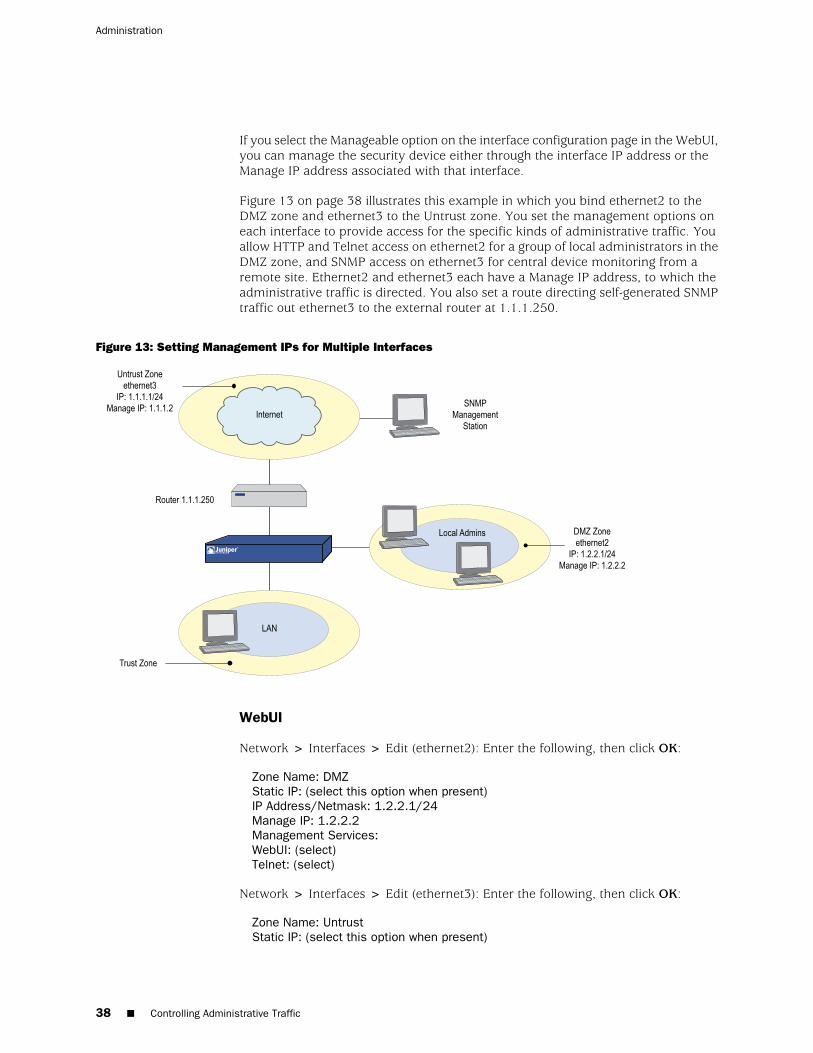
If you select the Manageable option on the interface configuration page in the WebUI,you can manage the security device either through the interface IP address or theManage IP address associated with that interface.
Figure 13 on page 38 illustrates this example in which you bind ethernet2 to theDMZ zone and ethernet3 to the Untrust zone. You set the management options oneach interface to provide access for the specific kinds of administrative traffic. Youallow HTTP and Telnet access on ethernet2 for a group of local administrators in theDMZ zone, and SNMP access on ethernet3 for central device monitoring from aremote site. Ethernet2 and ethernet3 each have a Manage IP address, to which theadministrative traffic is directed. You also set a route directing self-generated SNMPtraffic out ethernet3 to the external router at 1.1.1.250.
Figure 13: Setting Management IPs for Multiple Interfaces
WebUI
Network > Interfaces > Edit (ethernet2): Enter the following, then click OK:
Zone Name: DMZStatic IP: (select this option when present)IP Address/Netmask: 1.2.2.1/24Manage IP: 1.2.2.2Management Services:WebUI: (select)Telnet: (select)
Network > Interfaces > Edit (ethernet3): Enter the following, then click OK:
Zone Name: UntrustStatic IP: (select this option when present)
38 ■ Controlling Administrative Traffic
Administration
IP Address/Netmask: 1.1.1.1/24Manage IP: 1.1.1.2Management Services: SNMP: (select)
CLI
set interface ethernet2 zone dmzset interface ethernet2 ip 1.2.2.1/24set interface ethernet2 manage-ip 1.2.2.2set interface ethernet2 manage webset interface ethernet2 manage telnetset interface ethernet3 zone untrustset interface ethernet3 ip 1.1.1.1/24set interface ethernet3 manage-ip 1.1.1.2set interface ethernet3 manage snmpsave
Levels of Administration
Juniper Networks security devices support multiple administrative users. For anyconfiguration changes made by an administrator, the security device logs the followinginformation:
■ The name of the administrator making the change
■ The IP address from which the change was made
■ The time of the change
There are several levels of administrative user. The availability of some of these levelsdepends on the model of your Juniper Networks security device. The following sectionslist all the admin levels and the privileges for each level. These privileges are onlyaccessible to an admin after he or she successfully logs in with a valid username andpassword.
Root Administrator
The root administrator has complete administrative privileges. There is only one rootadministrator per security device. The root administrator has the following privileges:
■ Manages the root system of the security device
■ Adds, removes, and manages all other administrators
■ Assigns role attributes to all other administrators
■ Establishes and manages virtual systems and assigns physical or logical interfacesto them
■ Creates, removes, and manages virtual routers (VRs)
■ Adds, removes, and manages security zones
■ Assigns interfaces to security zones
■ Performs asset recovery
Levels of Administration ■ 39
Chapter 1: Administration
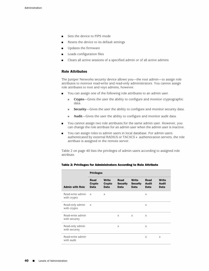
■ Sets the device to FIPS mode
■ Resets the device to its default settings
■ Updates the firmware
■ Loads configuration files
■ Clears all active sessions of a specified admin or of all active admins
Role Attributes
The Juniper Networks security device allows you—the root admin—to assign roleattributes to nonroot read-write and read-only administrators. You cannot assignrole attributes to root and vsys admins, however.
■ You can assign one of the following role attributes to an admin user.
■ Crypto—Gives the user the ability to configure and monitor cryptographicdata.
■ Security—Gives the user the ability to configure and monitor security data.
■ Audit—Gives the user the ability to configure and monitor audit data.
■ You cannot assign two role attributes for the same admin user. However, youcan change the role attribute for an admin user when the admin user is inactive.
■ You can assign roles to admin users in local database. For admin usersauthenticated by external RADIUS or TACACS+ authentication servers, the roleattribute is assigned in the remote server.
Table 2 on page 40 lists the privileges of admin users according to assigned roleattribute.
Table 2: Privileges for Administrators According to Role Attribute
Privileges
Admin with Role
WriteAuditData
ReadAuditData
WriteSecurityData
ReadSecurityData
WriteCryptoData
ReadCryptoData
xxxRead-write adminwith crypto
xxRead-only adminwith crypto
xxxRead-write adminwith security
xxRead-only adminwith security
xxRead-write adminwith audit
40 ■ Levels of Administration
Administration
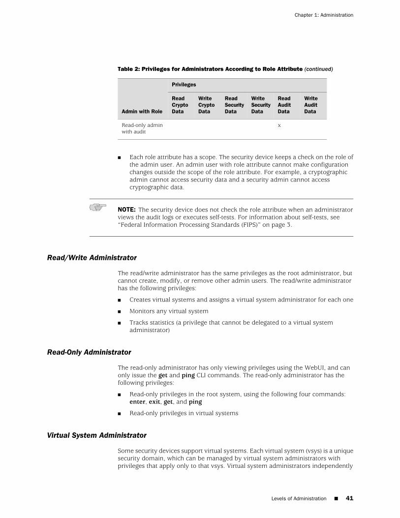
Table 2: Privileges for Administrators According to Role Attribute (continued)
Privileges
Admin with Role
WriteAuditData
ReadAuditData
WriteSecurityData
ReadSecurityData
WriteCryptoData
ReadCryptoData
xRead-only adminwith audit
■ Each role attribute has a scope. The security device keeps a check on the role ofthe admin user. An admin user with role attribute cannot make configurationchanges outside the scope of the role attribute. For example, a cryptographicadmin cannot access security data and a security admin cannot accesscryptographic data.
NOTE: The security device does not check the role attribute when an administratorviews the audit logs or executes self-tests. For information about self-tests, see“Federal Information Processing Standards (FIPS)” on page 3.
Read/Write Administrator
The read/write administrator has the same privileges as the root administrator, butcannot create, modify, or remove other admin users. The read/write administratorhas the following privileges:
■ Creates virtual systems and assigns a virtual system administrator for each one
■ Monitors any virtual system
■ Tracks statistics (a privilege that cannot be delegated to a virtual systemadministrator)
Read-Only Administrator
The read-only administrator has only viewing privileges using the WebUI, and canonly issue the get and ping CLI commands. The read-only administrator has thefollowing privileges:
■ Read-only privileges in the root system, using the following four commands:enter, exit, get, and ping
■ Read-only privileges in virtual systems
Virtual System Administrator
Some security devices support virtual systems. Each virtual system (vsys) is a uniquesecurity domain, which can be managed by virtual system administrators withprivileges that apply only to that vsys. Virtual system administrators independently
Levels of Administration ■ 41
Chapter 1: Administration
manage virtual systems through the CLI or WebUI. On each vsys, the virtual systemadministrator has the following privileges:
■ Creates and edits auth, IKE, L2TP, XAuth, and Manual Key users
■ Creates and edits services
■ Creates and edits policies
■ Creates and edits addresses
■ Creates and edits VPNs
■ Modifies the virtual system administrator login password
■ Creates and manages security zones
■ Adds and removes virtual system read-only administrators
Virtual System Read-Only Administrator
A virtual system read-only administrator has the same set of privileges as a read-onlyadministrator, but only within a specific virtual system. A virtual system read-onlyadministrator has viewing privileges for his particular vsys through the WebUI, andcan only issue the enter, exit, get, and ping CLI commands within his vsys.
NOTE: For more information on virtual systems, see Virtual Systems.
Defining Admin Users
The root administrator is the only one who can create, modify, and remove adminusers. In the following example, the one performing the procedure must be a rootadministrator.
Example: Adding a Read-Only Admin
In this example, you—as the root admin—add a read-only administrator namedRoger with password 2bd21wG7.
WebUI
Configuration > Admin > Administrators > New: Enter the following, then clickOK:
Name: RogerNew Password: 2bd21wG7Confirm New Password: 2bd21wG7Privileges: Read-Only (select)Role: None (default)
NOTE: The password can be up to 31 characters long and is case sensitive.
42 ■ Defining Admin Users
Administration
CLI
set admin user Roger password 2bd21wG7 privilege read-onlysave
Example: Modifying an Admin
In this example, you—as the root admin—change Roger’s privileges from read-onlyto read/write and assign a security role attribute. Roger and the root admin sharethe same privilege in managing security-related configuration changes.
WebUI
Configuration > Admin > Administrators > Edit (for Roger): Enter the following,then click OK:
Name: RogerNew Password: 2bd21wG7Confirm New Password: 2bd21wG7Privileges: Read-Write (select)Role: Security (select)
CLI
unset admin user Rogerset admin user Roger password 2bd21wG7 privilege allset admin user Roger role securitysave
Example: Deleting an Admin
In this example, you—as the root admin—delete the admin user Roger.
WebUI
Configuration > Admin > Administrators: Click Remove in the Configure columnfor Roger.
CLI
unset admin user Rogersave
Example: Configuring Admin Accounts for Dialup Connections
Some devices support a modem connection for outbound dialup disaster recoverysituations. You can set up trustee accounts for the interface, for the modem or forboth the interface and modem. This section describes the two types of trustees:
■ Interface trustee
Defining Admin Users ■ 43
Chapter 1: Administration
An interface trustee only has access to the WebUI and is restricted to the signalingmethods and IP address assignment for the primary Untrust interface.
For devices with ADSL interfaces, an interface trustee has control over thefollowing characteristics:
■ Layer 1 characteristics: VPI/VCI, multiplexing mode, RFC1483 bridged orrouted
■ Layer 2 signaling methods (PPPoE or PPPoA, and their parameters)
■ IP address assignment methods (statically defined by an administrator, ordynamically acquired from the circuit through PPPoE or PPPoA).
For devices with only ethernet interfaces, an interface trustee can controlhow the interface IP address is assigned (statically defined by administrator,or dynamically acquired from the circuit with DHCP or PPPoE).
■ Modem trustee
A modem trustee only has access to the WebUI and is restricted to Modem andISP settings for the serial interface. A modem trustee can created, modify, anddelete modem definitions to suit their specific needs, and can create, modify,and delete the settings for ISP1 and ISP2. A modem trustee can view theconfigurations for ISP3 and ISP4, and can test connectivity for any defined ISPand phone number.
You can view all administrator accounts by entering the get admin user command,or you can view only the trustee accounts by entering the get admin user trusteecommand.
In the following example, you configure a Read/Write modem trustee account forRichard Brockie. You set his username to be sdonovan and his password to be !23fb.
WebUI
Configuration > Admin > Administrators
CLI
set admin user sdonovan password !23fb privilege allset admin user sdonovan trustee modem
Example: Clearing an Admin’s Sessions
In this example, you—as the root admin—terminate all active sessions of the adminuser Roger. When you execute the following command, the security device closesall active sessions and automatically logs off Roger from the system.
44 ■ Defining Admin Users
Administration
WebUI
NOTE: You must use the CLI to clear an admin’s sessions.
CLI
clear admin name Rogersave
Securing Administrative Traffic
To secure the security device during setup, perform the following steps:
1. On the WebUI, change the administrative port.
See “Changing the Port Number” on page 46.
2. Change the username and password for administration access.
See “Changing the Admin Login Name and Password” on page 46
3. Define the management client IP addresses for the admin users.
See “Restricting Administrative Access” on page 49.
4. Turn off any unnecessary interface management service options.
See “Controlling Administrative Traffic” on page 33.
5. Disable the ping and ident-reset service options on the interfaces, both of whichrespond to requests initiated by unknown parties and can reveal informationabout your network:
WebUI
Network > Interfaces > Edit (for the interface you want to edit): Disable the followingservice options, then click OK:
Ping: Selecting this option allows the security device to respond to an ICMP echorequest, or “ping,” which determines whether a specific IP address is accessible fromthe device.
Ident-Reset: When a service such as Mail or FTP sends an identification request andreceives no acknowledgment, it sends the request again. While the request is inprogress, user access is disabled. With the Ident-Reset check box enabled, the securitydevice automatically restores user access.
CLI
unset interface interface manage ping
Securing Administrative Traffic ■ 45
Chapter 1: Administration
unset interface interface manage ident-reset
Changing the Port Number
Changing the port number to which the security device listens for HTTP managementtraffic improves security. The default setting is port 80, the standard port numberfor HTTP traffic. After you change the port number, you must then enter the newport number in the URL field in your browser when you next attempt to contact thesecurity device. (In the following example, the administrator needs to enterhttp://188.30.12.2:15522.)
In this example, the IP address of the interface bound to the Trust zone is 10.1.1.1/24.To manage the security device with the WebUI on this interface, you must use HTTP.To increase the security of the HTTP connection, you change the HTTP port numberfrom 80 (the default) to 15522.
WebUI
Configuration > Admin > Management: In the HTTP Port field, enter 15522, thenclick Apply.
CLI
set admin port 15522save
Changing the Admin Login Name and Password
By default, the initial login name for security devices is netscreen. The initial passwordis also netscreen. Because these have been widely published, we recommend youchange the login name and password immediately. The login name and passwordare both case-sensitive. They can contain any character that can be entered fromthe keyboard with the exception of ? and ". Record the new admin login name andpassword in a secure manner.
WARNING: Be sure to record your new password. If you forget it, you must resetthe security device to its factory settings, and all your configurations will be lost. Formore information, see “Resetting the Device to the Factory Default Settings” on page48.
Admin users for the security device can be authenticated using the internal databaseor an external auth server. When the admin user logs into the security device, it firstchecks the local internal database for authentication. If there is no entry present andan external auth server is connected, it then checks for a matching entry in theexternal auth server database. After an admin user successfully logs into an externalauth server, the security device maintains the admin’s login status locally.
46 ■ Securing Administrative Traffic
Administration
NOTE: Juniper Networks supports RADIUS, SecurID, and LDAP servers for adminuser authentication. (For more information, see Admin Users.) Although the rootadmin account must be stored on the local database, you can store root-levelread/write and root-level read-only admin users on an external auth server. To storeroot-level and vsys-level admin users on an external auth server and query theirprivileges, the server must be RADIUS and you must load the netscreen.dct file onit.For more information about admin user levels, see “Levels of Administration” onpage 39. For more about using external auth servers, see External AuthenticationServers.
When the root admin changes any attribute of an admin user’s profile—username,password, or privilege—any administrative session that the admin currently has openautomatically terminates. If the root admin changes any of these attributes for himself,or if a root-level read/write admin or vsys read/write admin changes his ownpassword, all of that user’s currently open admin sessions terminate, other than theone in which he made the change.
NOTE: The behavior of an HTTP or HTTPS session using the WebUI is different.Because HTTP does not support a persistent connection, any change that you maketo your own user profile automatically logs you out of that and all other open sessions.
Example: Changing an Admin User’s Login Name and Password
In this example, you—as the root admin—change a read/write administrator’s loginname from “John” to “Smith” and his password from xL7s62a1 to 3MAb99j2.
NOTE: Instead of using actual words for passwords, which might be guessed ordiscovered through a dictionary attack, you can use an apparently random string ofletters and numbers. To create such a string that you can easily remember, composea sentence and use the first letter from each word. For example, “Charles will be 6years old on November 21” becomes “Cwb6yooN21.”For more information, see “Levels of Administration” on page 39.
WebUI
Configuration > Admin > Administrators > Edit (for John): Enter the following,then click OK:
Name: SmithNew Password: 3MAb99j2Confirm New Password: 3MAb99j2
CLI
unset admin user Johnset admin user Smith password 3MAb99j2 privilege all
Securing Administrative Traffic ■ 47
Chapter 1: Administration
save
Example: Changing Your Own Password
Admin users with read/write privileges can change their own administrator password,but not their login name. In this example, an administrator with read/write privilegesand the login name “Smith” changes his password from 3MAb99j2 to ru494Vq5.
WebUI
Configuration > Admin > Administrators > Edit (for first entry): Enter the following,then click OK:
Name: SmithNew Password: ru494Vq5Confirm New Password: ru494Vq5
CLI
set admin password ru494Vq5save
Setting the Minimum Length of the Root Admin Password
In some corporations, one person might initially configure the device as the rootadmin, but another person later assumes the role of root admin and manages thedevice. To prevent the subsequent root admin from using short passwords that arepotentially easier to decode, the initial root admin can set a minimum lengthrequirement for the root admin’s password to any number from 1 to 31.
You can set the minimum password length only if you are the root admin and yourown password meets the minimum length requirement you are attempting to set.Otherwise, the security device displays an error message.
To specify a minimum length for the root admin’s password, enter the following CLIcommand:
set admin password restrict length number
NOTE: You must use the CLI to set this restriction.
Resetting the Device to the Factory Default Settings
If the admin password is lost, you can use the following procedure to reset the securitydevice to its default settings. The configurations will be lost, but access to the devicewill be restored. To perform this operation, you need to make a console connection,which is described in detail in ScreenOS CLI Reference Guide: IPv4 CommandDescriptions and the documentation for your device.
48 ■ Securing Administrative Traffic
Administration
NOTE: By default, the device recovery feature is enabled. You can disable it byentering the unset admin device-reset command. Also, if the security device is inFIPS mode, the recovery feature is automatically disabled.
1. At the login prompt, enter the serial number of the device.
2. At the password prompt, enter the serial number again.
The following message appears:
!!!! Lost Password Reset !!!! You have initiated a command to reset the device tofactory defaults, clearing all current configuration, keys and settings. Would youlike to continue? y/n
3. Press the y key.
The following message appears:
!! Reconfirm Lost Password Reset !! If you continue, the entire configuration ofthe device will be erased. In addition, a permanent counter will be incrementedto signify that this device has been reset. This is your last chance to cancel thiscommand. If you proceed, the device will return to factory default configuration,which is: System IP: 192.168.1.1; username: netscreen; password: netscreen.Would you like to continue? y/n
4. Press the y key to reset the device. You can now log in using netscreen as thedefault username and password.
Restricting Administrative Access
You can administer security devices from one or multiple addresses of a subnet. Bydefault, any host on the trusted interface can administer a security device. To restrictthis ability to specific workstations, you must configure management client IPaddresses.
Example: Restricting Administration to a Single Workstation
In this example, the administrator at the workstation with the IP address 172.16.40.42is the only administrator specified to manage the security device.
WebUI
Configuration > Admin > Permitted IPs: Enter the following, then click Add:
IP Address / Netmask: 172.16.40.42/32
CLI
set admin manager-ip 172.16.40.42/32save
Securing Administrative Traffic ■ 49
Chapter 1: Administration
Example: Restricting Administration to a Subnet
In this example, the group of administrators with workstations in the 172.16.40.0/24subnet are specified to manage a security device.
WebUI
Configuration > Admin > Permitted IPs: Enter the following, then click Add:
IP Address / Netmask: 172.16.40.0/24
CLI
set admin manager-ip 172.16.40.0 255.255.255.0set admin manager-ip 3ffe:7777::1/32set admin manager-ip 3ffe:7777::1/24save
Restricting the Root Admin to Console Access
You can also require the root admin to log into the security device through the consoleonly. This restriction requires the root admin to have physical access to the deviceto log in, thus preventing unauthorized users from logging in remotely as the rootadmin. After you have set this restriction, the device denies access if anyone triesto log in as the root admin through other means, such as the WebUI, Telnet, or SSH,even if these management options are enabled on the ingress interface.
To restrict the access of the root admin to the console only, enter the followingcommand:
set admin root access console
NOTE: You must use the CLI to set this restriction.
Monitoring Admin access
ScreenOS provides the following features to monitor and control the admin accessto the security devices:
Lock and unlock interactive session
Users will be able to lock and unlock the current active session by using Exitcommand.
Auto lock after inactivity
ScreenOS supports this feature by employing three components:
50 ■ Securing Administrative Traffic
Administration

■ When the administrator is inactive on the terminal for a specified period of timethe device automatically locks the session. Root-admins can specify the timeperiod of inactivity after which the device locks the session by using the setconsole time command.
■ When the administrator locks a session by using the exit command or when thedevice auto-locks the session, the security device clears all contents or overwritesthe contents on display devices making it unreadable. About 50 empty lines willbe flushed out on the display devices.
■ After locking the session, any activity other than unlocking the session will bedisabled. Users will be denied access to data in ScreenOS withoutreauthentication.
Restrict admin access based on time
ScreenOS restricts the admin access to users based on location by using the setadmin manager command. For example, the following command restrictsmanagement to a single host with IP address 10.1.10.100:
set admin manager-ip 10.1.10.100 255.255.255.255
To restrict admin access based on time, use the set admin user user_name accessschedule scheduler_name. When a new connection initiated by certain admin comesat firewall, the scheduler bound to the admin is checked to see if the permit timewindow is open. If not, the connection request will be rejected. The scheduler willbe checked every 10 seconds and once the stop time is due, the admin will berestricted access to the security device.
You can view details of admins who are currently active by using the get activeadmin user login command:
ssg5-serial-> get admin user login
No Name Vsys Date Time Source IP Addr Auth Type Role Time Remain--- ---------- ---------- ---------- -------- ------- --------------- ------- --- ---------- ---------- ---------- -------- ------- --------------- -------1 kkk Root 2008-04-23 17:53:01 console 0.0.0.0 local - N/A 2 kkk Root 2008-04-23 17:49:26 web 2.2.2.2 local - N/A
To view details of all administrators use the get admin user command:
ssg5-serial-> get admin user
Name Privilege Role Scheduler -------------- --------------- ---------------kkk Root - N/A rrr Read-Write - N/A jjj Read-Only - N/A bbb Read-Only - N/A 11 Read-Only - N/A
Securing Administrative Traffic ■ 51
Chapter 1: Administration
VPN Tunnels for Administrative Traffic
You can use virtual private network (VPN) tunnels to secure remote management ofa security device from either a dynamically assigned or fixed IP address. Using aVPN tunnel, you can protect any kind of traffic, such as NSM, HTTP, Telnet, or SSH.(For information about creating a VPN tunnel to secure self-initiated traffic such asNSM reports, syslog reports, or SNMP traps, see “Configuring a MIB Filter in theSNMP Community” on page 96.)
Juniper Networks security devices support two types of VPN tunnel configurations:
■ Route-based VPNs: The security device uses route table entries to direct trafficto tunnel interfaces, which are bound to VPN tunnels.
■ Policy-based VPNs: The security device uses the VPN tunnel names specificallyreferenced in policies to direct traffic through VPN tunnels.
For each VPN tunnel configuration type, there are the following types of VPN tunnel:
■ Manual key: You manually set the three elements that define a SecurityAssociation (SA) at both ends of the tunnel: a Security Parameters Index (SPI),an encryption key, and an authentication key. To change any element in the SA,you must manually enter it at both ends of the tunnel.
■ AutoKey IKE with pre-shared key: One or two pre-shared secrets—one forauthentication and one for encryption—function as seed values. Using them, theIKE protocol generates a set of symmetrical keys at both ends of the tunnel; thatis, the same key is used to encrypt and decrypt. At predetermined intervals,these keys are automatically regenerated.
■ AutoKey IKE with certificates: Using the Public Key Infrastructure (PKI), theparticipants at both ends of the tunnel use a digital certificate (for authentication)and an RSA public/private key pair (for encryption). The encryption isasymmetrical; that is, one key in a pair is used to encrypt and the other todecrypt.
NOTE: For a complete description of VPN tunnels, see Virtual Private Networks. Formore information on NetScreen-Remote, see the NetScreen-Remote VPN ClientAdministrator Guide.
If you use a policy-based VPN configuration, you must create an address book entrywith the IP address of an interface in any zone other than the one to which theoutgoing interface is bound. You can then use that as the source address in policiesreferencing the VPN tunnel. This address also serves as the end entity address forthe remote IPsec peer. If you are using a route-based VPN configuration, such anaddress book entry is unnecessary.
Administration Through a Route-Based Manual Key VPN Tunnel
Figure 14 on page 53 illustrates an example in which you set up a route-based ManualKey VPN tunnel to provide confidentiality for administrative traffic. The tunnel extends
52 ■ Securing Administrative Traffic
Administration
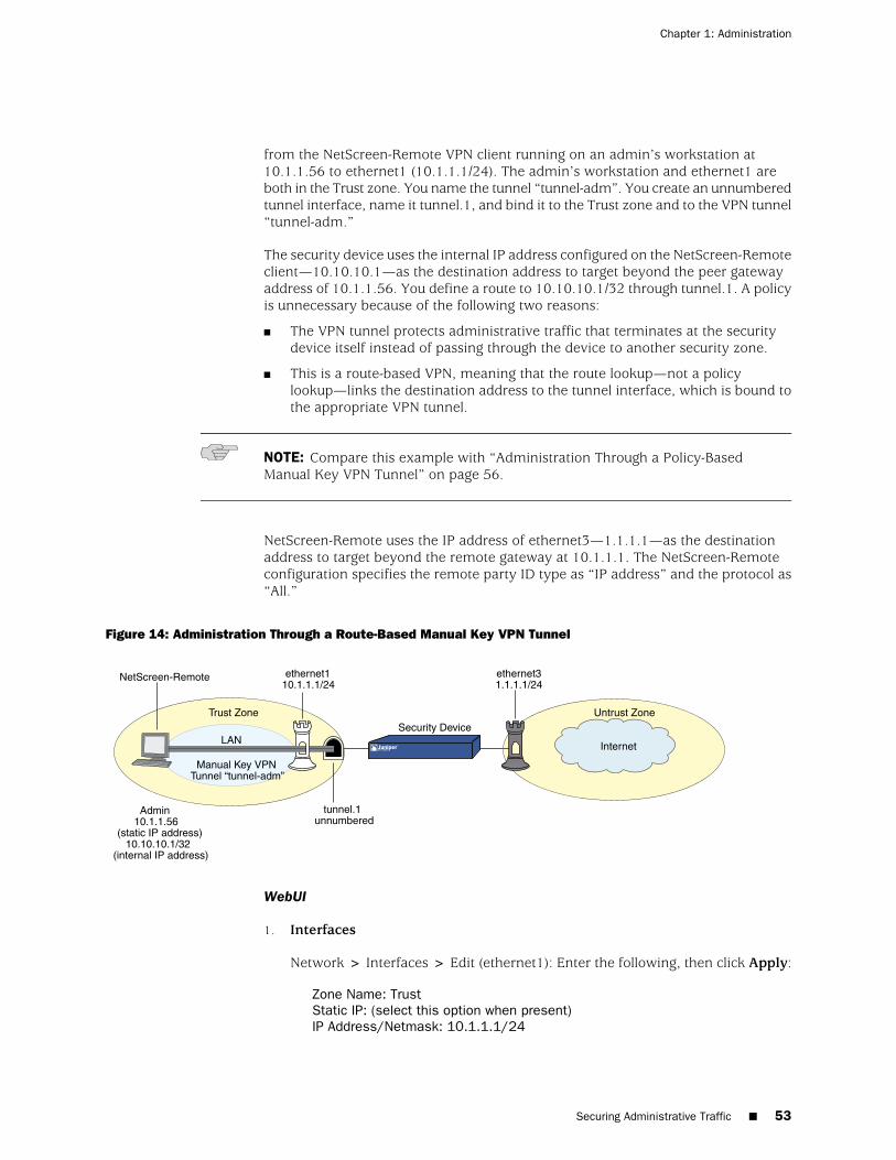
from the NetScreen-Remote VPN client running on an admin’s workstation at10.1.1.56 to ethernet1 (10.1.1.1/24). The admin’s workstation and ethernet1 areboth in the Trust zone. You name the tunnel “tunnel-adm”. You create an unnumberedtunnel interface, name it tunnel.1, and bind it to the Trust zone and to the VPN tunnel“tunnel-adm.”
The security device uses the internal IP address configured on the NetScreen-Remoteclient—10.10.10.1—as the destination address to target beyond the peer gatewayaddress of 10.1.1.56. You define a route to 10.10.10.1/32 through tunnel.1. A policyis unnecessary because of the following two reasons:
■ The VPN tunnel protects administrative traffic that terminates at the securitydevice itself instead of passing through the device to another security zone.
■ This is a route-based VPN, meaning that the route lookup—not a policylookup—links the destination address to the tunnel interface, which is bound tothe appropriate VPN tunnel.
NOTE: Compare this example with “Administration Through a Policy-BasedManual Key VPN Tunnel” on page 56.
NetScreen-Remote uses the IP address of ethernet3—1.1.1.1—as the destinationaddress to target beyond the remote gateway at 10.1.1.1. The NetScreen-Remoteconfiguration specifies the remote party ID type as “IP address” and the protocol as“All.”
Figure 14: Administration Through a Route-Based Manual Key VPN Tunnel
LAN
Untrust ZoneTrust Zone
Manual Key VPNTunnel “tunnel-adm”
ethernet110.1.1.1/24
ethernet31.1.1.1/24
NetScreen-Remote
Admin10.1.1.56
(static IP address)10.10.10.1/32
(internal IP address)
Security Device
tunnel.1unnumbered
Internet
WebUI
1. Interfaces
Network > Interfaces > Edit (ethernet1): Enter the following, then click Apply:
Zone Name: TrustStatic IP: (select this option when present)IP Address/Netmask: 10.1.1.1/24
Securing Administrative Traffic ■ 53
Chapter 1: Administration
Select the following, then click OK:
Interface Mode: NAT
Network > Interfaces > Edit (ethernet3): Enter the following, then click OK:
Zone Name: UntrustStatic IP: (select this option when present)IP Address/Netmask: 1.1.1.1/24
Network > Interfaces > New Tunnel IF: Enter the following, then click OK:
Tunnel Interface Name: Tunnel.1Zone (VR): Trust (trust-vr)Unnumbered: (select) Interface: ethernet1(trust-vr)
NOTE: The unnumbered tunnel interface borrows the IP address of the specifiedsecurity zone interface.
2. VPN
VPNs > Manual Key > New: Enter the following, then click OK:
VPN Tunnel Name: tunnel-admGateway IP: 10.1.1.56Security Index (HEX Number): 5555 (Local) 5555 (Remote)Outgoing Interface: ethernet1ESP-CBC: (select)Encryption Algorithm: DES-CBCGenerate Key by Password: netscreen1Authentication Algorithm: MD5Generate Key by Password: netscreen2
> Advanced: Enter the following, then click Return to set the advanced optionsand return to the basic configuration page:
Bind to Tunnel Interface: (select), Tunnel.1
NOTE: Because NetScreen-Remote processes passwords into keys differently thando other Juniper Networks products, after you configure the tunnel you need to dothe following: (1) Return to the Manual Key Configuration dialog box (click Edit inthe Configure column for “tunnel-adm”); (2) copy the generated hexadecimal keys;(3) use those hexadecimal keys when configuring the NetScreen-Remote end of thetunnel.
3. Route
Network > Routing > Destination > trust-vr New: Enter the following, thenclick OK:
54 ■ Securing Administrative Traffic
Administration
Network Address/Netmask: 10.10.10.1/32Gateway: (select)Interface: Tunnel.1Gateway IP Address: 0.0.0.0
CLI
1. Interfaces
set interface ethernet1 zone trustset interface ethernet1 ip 10.1.1.1/24set interface ethernet1 natset interface ethernet3 zone untrustset interface ethernet3 ip 1.1.1.1/24set interface tunnel.1 zone trustset interface tunnel.1 ip unnumbered interface ethernet1
NOTE: The unnumbered tunnel interface borrows the IP address of the specifiedsecurity zone interface.
2. VPN
set vpn tunnel-adm manual 5555 5555 gateway 10.1.1.56 outgoing ethernet1esp des password netscreen1 auth md5 password netscreen2
set vpn tunnel-adm bind interface tunnel.1
NOTE: Because NetScreen-Remote processes passwords into keys differently thando other Juniper Networks products, after you configure the tunnel you need to dothe following: (1) Enter get vpn admin-tun; (2) copy the hexadecimal keys generatedby “netscreen1” and “netscreen2” ; (3) use those hexadecimal keys when configuringthe NetScreen-Remote end of the tunnel.
3. Route
set vrouter trust-vr route 10.10.10.1/32 interface tunnel.1save
NetScreen-Remote Security Policy Editor
1. Click Options > Global Policy Settings, and select the Allow to Specify InternalNetwork Address check box.
2. Click Options > Secure > Specified Connections.
3. Click Add a new connection, and enter Admin next to the new connection iconthat appears.
4. Configure the connection options:
Connection Security: Secure
Securing Administrative Traffic ■ 55
Chapter 1: Administration
Remote Party Identity and Addressing:ID Type: IP Address, 1.1.1.1Protocol: AllConnect using Secure Gateway Tunnel: (select) ID Type: IP Address, 10.1.1.1
5. Click the PLUS symbol, located to the left of the UNIX icon, to expand theconnection policy.
6. Click My Identity, in the Select Certificate drop-down list, choose None, and inthe Internal Network IP Address, enter 10.10.10.1.
7. Click Security Policy, and select Use Manual Keys.
8. Click the PLUS symbol, located to the left of the Security Policy icon, then clickthe PLUS symbol to the left of Key Exchange (Phase 2) to expand the policyfurther.
9. Click Proposal 1, then select the following IPsec protocols:
Encapsulation Protocol (ESP): (select)Encrypt Alg: DESHash Alg: MD5Encapsulation: Tunnel
10. Click Inbound Keys, and in the Security Parameters Index field, enter 5555.
11. Click Enter Key, enter the following, then click OK:
Choose key format: BinaryESP Encryption Key: dccbee96c7e546bcESP Authentication Key: dccbe9e6c7e546bcb0b667794ab7290c
NOTE: These are the two generated keys that you copied after configuring the securitydevice.
12. Click Outbound Keys, and, in the Security Parameters Index field, enter 5555.
13. Click Enter Key, enter the following, then click OK:
Choose key format: BinaryESP Encryption Key: dccbee96c7e546bcESP Authentication Key: dccbe9e6c7e546bcb0b667794ab7290c
14. Click Save.
Administration Through a Policy-Based Manual Key VPN Tunnel
Figure 15 on page 57 illustrates an example in which you set up a policy-basedManual Key VPN tunnel for administrative traffic. The tunnel extends from theNetScreen-Remote VPN client running on an admin’s workstation at 10.1.1.56 toethernet1 (10.1.1.1/24). The admin’s workstation and ethernet1 are both in the Trustzone. You name the tunnel “tunnel-adm” and bind it to the Trust zone.
56 ■ Securing Administrative Traffic
Administration
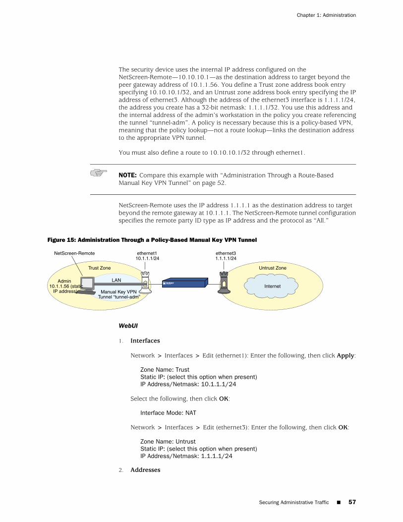
The security device uses the internal IP address configured on theNetScreen-Remote—10.10.10.1—as the destination address to target beyond thepeer gateway address of 10.1.1.56. You define a Trust zone address book entryspecifying 10.10.10.1/32, and an Untrust zone address book entry specifying the IPaddress of ethernet3. Although the address of the ethernet3 interface is 1.1.1.1/24,the address you create has a 32-bit netmask: 1.1.1.1/32. You use this address andthe internal address of the admin’s workstation in the policy you create referencingthe tunnel “tunnel-adm”. A policy is necessary because this is a policy-based VPN,meaning that the policy lookup—not a route lookup—links the destination addressto the appropriate VPN tunnel.
You must also define a route to 10.10.10.1/32 through ethernet1.
NOTE: Compare this example with “Administration Through a Route-BasedManual Key VPN Tunnel” on page 52.
NetScreen-Remote uses the IP address 1.1.1.1 as the destination address to targetbeyond the remote gateway at 10.1.1.1. The NetScreen-Remote tunnel configurationspecifies the remote party ID type as IP address and the protocol as “All.”
Figure 15: Administration Through a Policy-Based Manual Key VPN Tunnel
Untrust ZoneTrust Zone
Admin10.1.1.56 (static
IP address) Manual Key VPNTunnel “tunnel-adm”
ethernet110.1.1.1/24
ethernet31.1.1.1/24
NetScreen-Remote
InternetLAN
WebUI
1. Interfaces
Network > Interfaces > Edit (ethernet1): Enter the following, then click Apply:
Zone Name: TrustStatic IP: (select this option when present)IP Address/Netmask: 10.1.1.1/24
Select the following, then click OK:
Interface Mode: NAT
Network > Interfaces > Edit (ethernet3): Enter the following, then click OK:
Zone Name: UntrustStatic IP: (select this option when present)IP Address/Netmask: 1.1.1.1/24
2. Addresses
Securing Administrative Traffic ■ 57
Chapter 1: Administration
Policy > Policy Elements > Addresses > Lists > New: Enter the following, thenclick OK:
Address Name: Untrust-IFIP Address/Domain Name: IP/Netmask: (select), 1.1.1.1/32Zone: Untrust
Policy > Policy Elements > Addresses > Lists > New: Enter the following, thenclick OK:
Address Name: adminIP Address/Domain Name: IP/Netmask: (select), 10.10.10.1/32Zone: Trust
3. VPN
VPNs > Manual Key > New: Enter the following, then click OK:
VPN Tunnel Name: tunnel-admGateway IP: 10.1.1.56Security Index (HEX Number): 5555 (Local) 5555 (Remote)Outgoing Interface: ethernet1ESP-CBC: (select)Encryption Algorithm: DES-CBCGenerate Key by Password: netscreen1Authentication Algorithm: MD5Generate Key by Password: netscreen2
NOTE: Because NetScreen-Remote processes passwords into keys differently thando other Juniper Networks products, after you configure the tunnel you need to dothe following: (1) Return to the Manual Key Configuration dialog box (click Edit inthe Configure column for “tunnel-adm”); (2) copy the generated hexadecimal keys;(3) use those hexadecimal keys when configuring the NetScreen-Remote end of thetunnel.
4. Route
Network > Routing > Destination > trust-vr New: Enter the following, thenclick OK:
Network Address/Netmask: 10.10.10.1/32Gateway: (select) Interface: ethernet1 Gateway IP Address: 0.0.0.0
5. Policies
Policies > (From: Trust, To: Untrust) New: Enter the following, then click OK:
Source Address: Address Book Entry: (select), admin
58 ■ Securing Administrative Traffic
Administration
Destination Address: Address Book Entry: (select), Untrust-IFService: AnyAction: TunnelTunnel: VPN: tunnel-admModify matching bidirectional VPN policy: (select)Position at Top: (select)
CLI
1. Interfaces
set interface ethernet1 zone trustset interface ethernet1 ip 10.1.1.1/24set interface ethernet1 natset interface ethernet3 zone untrustset interface ethernet3 ip 1.1.1.1/24
2. Addresses
set address trust admin 10.10.10.1/32set address untrust Untrust-IF 1.1.1.1/32
3. VPN
set vpn tunnel-adm manual 5555 5555 gateway 10.1.1.56 outgoing ethernet1 esp des password netscreen1 auth md5 password netscreen2
NOTE: Because NetScreen-Remote processes passwords into keys differently thando other Juniper Networks products, after you configure the tunnel you need to dothe following: (1) Enter get vpn admin-tun; (2) copy the hexadecimal keys generatedby “netscreen1” and “netscreen2” ; (3) use those hexadecimal keys when configuringthe NetScreen-Remote end of the tunnel.
4. Route
set vrouter trust-vr route 10.10.10.1/32 interface ethernet1
5. Policies
set policy top from trust to untrust admin Untrust-IF any tunnel vpn tunnel-admset policy top from untrust to trust Untrust-IF admin any tunnel vpn tunnel-admsave
NetScreen-Remote Security Policy Editor
1. Click Options > Secure > Specified Connections.
2. Click Add a new connection, and enter Admin next to the new connection iconthat appears.
Securing Administrative Traffic ■ 59
Chapter 1: Administration
3. Configure the connection options:
Connection Security: SecureRemote Party Identity and Addressing: ID Type: IP Address, 1.1.1.1 Protocol: All Connect using Secure Gateway Tunnel: (select) ID Type: IP Address, 10.1.1.1
4. Click the PLUS symbol, located to the left of the UNIX icon, to expand theconnection policy.
5. Click My Identity, and, in the Select Certificate drop-down list, choose None.
6. Click Security Policy, and select Use Manual Keys.
7. Click the PLUS symbol, located to the left of the Security Policy icon, and thenthe PLUS symbol to the left of Key Exchange (Phase 2) to expand the policyfurther.
8. Click Proposal 1, and select the following IPsec protocols:
Encapsulation Protocol (ESP): (select)Encrypt Alg: DESHash Alg: MD5Encapsulation: Tunnel
9. Click Inbound Keys, and in the Security Parameters Index field, enter 5555.
10. Click Enter, enter the following, and click OK:
Choose key format: BinaryESP Encryption Key: dccbee96c7e546bcESP Authentication Key: dccbe9e6c7e546bcb0b667794ab7290c
NOTE: These are the two generated keys that you copied after configuring the securitydevice.
11. Click Outbound Keys, and in the Security Parameters Index field, enter 5555.
12. Click Enter Key, enter the following, then click OK:
Choose key format: BinaryESP Encryption Key: dccbee96c7e546bcESP Authentication Key: dccbe9e6c7e546bcb0b667794ab7290c
13. Click Save.
Password Policy
The password policy feature allows you to enforce a minimum length and acomplexity scheme for administrator (admin) and authenticated (auth) userpasswords. The password policy feature is intended for use in a local database, andtherefore is useful in environments where the Windows directory or RADIUS are notavailable to provide centralized password policy enforcement.
60 ■ Password Policy
Administration
Setting a Password Policy
You can create a password policy to require that admin and auth passwords fulfillone or both of the following:
■ Minimum length
■ Complexity
The range for password minimum length is 1 to 32 characters. Use the followingcommand to create a password policy requiring a minimum length of 8 charactersfor admin passwords:
set password-policy user-type admin minimum-length 8
Password complexity means passwords must include at least two uppercase letters,two lowercase letters, and two alphanumeric and two non-alphanumeric characters;for example: AAbb12@#. To require that passwords contain complexity, you setcomplexity to 1. To unset the complexity requirement, set complexity to 0. Use thefollowing command to create a password policy requiring that auth passwords containcomplexity:
set password-policy user-type auth complexity 1
In the following example, you create a password policy for admin and auth accountsrequiring complexity and a minimum length of 8 characters:
CLI
set password-policy user-type admin minimum-length 8set password-policy user-type admin complexity 1set password-policy user-type auth minimum-length 8set password-policy user-type auth complexity 1save
NOTE: You can configure a password policy only from the command line interface(CLI).
Removing a Password Policy
Use the unset password-policy command to delete a password policy. When youremove a password policy, the password requirement for the account reverts to thedefault settings. In the following example, you remove the minimum lengthrequirement for auth passwords.
CLI
unset password-policy user-type auth minimum-length
Password Policy ■ 61
Chapter 1: Administration

Viewing a Password Policy
Use the get password-policy command to display the password policy for adminand auth users.
Recovering from a Rejected Default Admin Password
When you delete (unset) the root admin account on a device on which you have apassword policy configured, you might need to set a new admin password beforelogging off the system. This is because ScreenOS reverts to the default password(netscreen) when you delete the root admin account. If you have a password policyrequiring complexity, or a minimum length greater than 9 characters, your next loginattempt will fail. If this happens, use the asset recovery procedure to gain access tothe device. Refer to the installation and configuration guide for your device for details.
In the following example, you delete the admin account named admin2005, thendisplay the current password policy. As shown, the policy specifies that passwordsmust have a minimum length of 8 characters, and use complexity (a minimum oftwo uppercase, two lowercase, two alphanumeric, and two non-alphanumericcharacters). You then create a new admin account named admin2006 and set apassword for it that fulfills the minimum length and complexity requirements of thepassword policy.
CLI
unset admin admin2005get password-policy
user-type: adminpassword minimum length: 8password complexity scheme: 1
user-type: authpassword minimum length: 8password complexity scheme: 1
set admin admin2006 password AAbb12@#save
NOTE: You can configure an admin account only from the command line interface(CLI).
Creating a Login Banner
The size of the login banner is increased to a maximum of 4Kbytes. This providesspace for terms of use statements, which are presented before administrators andauthenticated users log into the security device and into protected resources behindthe device. The login banner is a clear text ASCII file you create and store on thesecurity device, the file must be called usrterms.txt. You activate the banner by
62 ■ Creating a Login Banner
Administration

restarting of the device. If the banner file is greater than 4Kbytes, the security devicewill not accept it and will continue using existing banners entered through the CLIand the WebUI.
When activated, the login banner is used globally by the root device and all virtualsystems (vsys). You cannot differentiate or customize between or within a vsys. Thelogin banner preempts all individually defined administrative access banners andfirewall authentication banners. After entering a username and password, the usermust click the Login button. Pressing the Enter key will not log the user into thedevice.
Use the SCP utility to securely copy the banner file to the security device. With thefollowing command, an administrator with username netscreen copies the bannerfile my_large_banner.txt to a security device at IP address 1.1.1.2. The banner filemust be saved on the security device as usrterms.txt.
You must restart the device to activate the new banner. To modify the banner file,create a new file and overwrite the existing one with the new one.
To remove the banner, issue the following command on the security device:
device-> delete file usrterms.txt
This disables the login banner feature after you restart the device.
Creating a Login Banner ■ 63
Chapter 1: Administration

64 ■ Creating a Login Banner
Administration
Chapter 2
Monitoring Security Devices
This chapter discusses the following topics about monitoring Juniper Networks securitydevices. It contains the following sections:
■ Storing Log Information on page 65
■ Event Log on page 66
■ Traffic Log on page 70
■ Self Log on page 75
■ Downloading the Asset Recovery Log on page 78
■ Traffic Alarms on page 79
■ Security Alarms and Audit Logs on page 82
■ Syslog on page 86
■ Simple Network Management Protocol on page 91
■ VPN Tunnels for Self-Initiated Traffic on page 101
■ Viewing Screen Counters on page 116
Storing Log Information
All Juniper Networks security devices allow you to store event and traffic log datainternally (in flash storage) and externally (in a number of locations). Although storinglog information internally is convenient, the amount of device memory is limited.When the internal storage space completely fills up, the security device beginsoverwriting the oldest log entries with the latest ones. If this first-in-first-out (FIFO)mechanism occurs before you save the logged information, you can lose data. Tomitigate such data loss, you can store event and traffic logs externally in a syslog orWebTrends server or in the NetScreen-Global PRO database. The security devicesends new event and traffic log entries to an external storage location every second.
The following list provides the possible destinations for logged data:
■ Console: A destination for all log entries to appear when you are troubleshootinga security device through the console. Optionally, you might elect to have onlyalarm messages (critical, alert, emergency) appear here to alert you immediatelyif you happen to be using the console at the time an alarm is triggered.
■ Internal: Allows you store a limited number of log entries.
■ Email: A method for sending event and traffic logs to remote administrators.
Storing Log Information ■ 65
■ SNMP: In addition to the transmission of SNMP traps, a security device can alsosend alarm messages (critical, alert, emergency) from its event log to an SNMPcommunity.
■ Syslog: All event and traffic log entries that a security device can store internally,it can also send to a syslog server. Because syslog servers have a much greaterstorage capacity than the internal flash storage on a security device, sendingdata to a syslog server can mitigate data loss that might occur when log entriesexceed the maximum internal storage space. Syslog stores alert- andemergency-level events in the security facility that you specify, and all otherevents (including traffic data) in the facility you specify.
■ WebTrends: Allows you to view log data for critical-, alert-, and emergency-levelevents in a more graphical format than syslog, which is a text-based tool.
■ CompactFlash (PCMCIA): Allows you to store data on a CompactFlash card.
■ USB: Allows you to store data on a USB flash drive. When you set USB as the logdestination, the system sends log messages to a file on the USB flash drive. Thelog file is named hostname_date.evt_log, where hostname is the system hostnameat boot time, and date is date on which the device was last started. Logging toUSB is disabled by default; use the set log usb enable CLI command to enableUSB logging.
Use the set log... destination... command to set the severity levels for all logdestinations. The following example logs all system module messages of level criticalor higher to the USB flash drive:
set log module system level critical destination usb
Event Log
ScreenOS provides an event log for monitoring system events such asadmin-generated configuration changes, and self-generated messages and alarmsregarding operational behavior and attacks. The security device categorizes systemevents by the following severity levels:
■ Emergency: Messages on SYN attacks, Tear Drop attacks, and Ping of Deathattacks. For more information on these types of attacks, see Attack Detectionand Defense Mechanisms.
■ Alert: Messages about conditions that require immediate attention, such asfirewall attacks and the expiration of license keys.
■ Critical: Messages about conditions that probably affect the functionality of thedevice, such as high availability (HA) status changes.
■ Error: Messages about error conditions that probably affect the functionality ofthe device, such as a failure in antivirus scanning or in communicating with SSHservers.
■ Warning: Messages about conditions that could affect the functionality of thedevice, such as a failure to connect to email servers or authentication failures,timeouts, and successes.
■ Notification: Messages about normal events, including configuration changesinitiated by an admin.
66 ■ Event Log
Administration
■ Information: Messages that provide general information about system operations.
■ Debugging: Messages that provide detailed information used for debuggingpurposes.
The event log displays the date, time, level and description of each system event.You can view system events for each category stored in flash storage on the securitydevice through the WebUI or the CLI. You can also open or save the file to the locationyou specify, and then use an ASCII text editor (such as Notepad or WordPad) to viewthe file. Alternatively, you can send them to an external storage space (see “StoringLog Information” on page 65).
NOTE: For detailed information about the messages that appear in the event log, seethe ScreenOS Message Log Reference Guide.
Viewing the Event Log by Severity Level and Keyword
You can view the event log stored in the device by using the CLI or the WebUI. Youcan display log entries by severity level and search the event log by keyword in boththe WebUI and CLI.
To display the event log by severity level, do either of the following:
WebUI
Reports > System Log > Event: Select a severity level from the Log Level drop-downlist.
CLI
get event level { emergency | alert | critical | error | warning | notification | information | debugging }
To search the event log by keyword, do either of the following:
WebUI
Reports > System Log > Event: Enter a word or phrase up to 15 characters in lengthin the search field, then click Search.
CLI
get event include word_string
In this example, you view event log entries with a “warning” severity level and do asearch for the keyword AV.
Event Log ■ 67
Chapter 2: Monitoring Security Devices
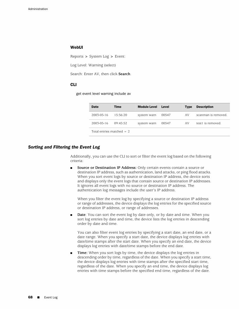
WebUI
Reports > System Log > Event:
Log Level: Warning (select)
Search: Enter AV, then click Search.
CLI
get event level warning include av
DescriptionTypeLevelModule LevelTimeDate
scanman is removed.AV00547system warn15:56:202003-05-16
test1 is removed.AV00547system warn09:45:522003-05-16
Total entries matched = 2
Sorting and Filtering the Event Log
Additionally, you can use the CLI to sort or filter the event log based on the followingcriteria:
■ Source or Destination IP Address: Only certain events contain a source ordestination IP address, such as authentication, land attacks, or ping flood attacks.When you sort event logs by source or destination IP address, the device sortsand displays only the event logs that contain source or destination IP addresses.It ignores all event logs with no source or destination IP address. Theauthentication log messages include the user’s IP address.
When you filter the event log by specifying a source or destination IP addressor range of addresses, the device displays the log entries for the specified sourceor destination IP address, or range of addresses.
■ Date: You can sort the event log by date only, or by date and time. When yousort log entries by date and time, the device lists the log entries in descendingorder by date and time.
You can also filter event log entries by specifying a start date, an end date, or adate range. When you specify a start date, the device displays log entries withdate/time stamps after the start date. When you specify an end date, the devicedisplays log entries with date/time stamps before the end date.
■ Time: When you sort logs by time, the device displays the log entries indescending order by time, regardless of the date. When you specify a start time,the device displays log entries with time stamps after the specified start time,regardless of the date. When you specify an end time, the device displays logentries with time stamps before the specified end time, regardless of the date.
68 ■ Event Log
Administration
When you specify both a start and end time, the device displays log entries withtime stamps within the specified time period.
■ Message Type ID Number: You can display event log entries for a specificmessage type ID number, or you can display log entries with message type IDnumbers within a specified range. The device displays log entries with themessage type ID number(s) you specified, in descending order by date and time.
In this example you view event log entries that contain source IP addresses withinthe range 10.100.0.0 to 10.200.0.0. The log entries are also sorted by source IPaddress.
WebUI
NOTE: You must use the CLI to sort the event log by address entries.
CLI
get event sort-by src-ip 10.100.0.0-10.200.0.0
Downloading the Event Log
You can open or save the event log to the location you specify, and then use an ASCIItext editor (such as Notepad or WordPad) to view the file. Alternatively, you can sendthe log entries to an external storage space (see “Storing Log Information” on page65). You can download the entire event log through the WebUI. You can downloadthe event log by severity level through the CLI.
Example: Downloading the Entire Event Log
In this example, you download the event log to the local directory. Using the WebUI,you download it to C:\netscreen\logs. Using the CLI, you download it to the rootdirectory of a TFTP server at the IP address 10.1.1.5. You name the file“evnt07-02.txt.”
WebUI
1. Reports > System Log > Event: Click Save.
The File Download dialog box prompts you to open the file (using an ASCII editor)or save it to disk.
2. Select the Save option, then click OK.
The File Download dialog box prompts you to choose a directory.
3. Specify C:\netscreen\logs, name the file evnt07-02.txt, then click Save.
Event Log ■ 69
Chapter 2: Monitoring Security Devices
CLI
get event > tftp 10.1.1.5 evnt07-02.txt
Example: Downloading the Event Log for Critical Events
In this example, you download the critical events entered in the event log to the rootdirectory of a TFTP server at the IP address 10.1.1.5. You name the filecrt_evnt07-02.txt.
WebUI
NOTE: You must use the CLI to download entries by severity level.
CLI
get event level critical > tftp 10.1.1.5 crt_evnt07-02.txt
Traffic Log
The Juniper Networks security device can monitor and record traffic that it permitsor denies based on previously configured policies. You can enable the logging optionfor each policy that you configure. When you enable the logging option for a policythat permits traffic, the device records the traffic allowed by that policy. When youenable the logging option for a policy that denies traffic, the device records trafficthat attempted to pass through the device, but was dropped because of that policy.
A traffic log notes the following elements for each session:
■ Date and time that the connection started
■ Duration
■ Source address and port number
■ Translated source address and port number
■ Destination address and port number
■ The duration of the session
■ The service used in the session
To log all traffic that a security device receives, you must enable the logging optionfor all policies. To log specific traffic, enable logging only on policies that apply tothat traffic. To enable the logging option on a policy, do either of the following:
WebUI
Policies > (From: src_zone, To: dst_zone) New: Select Logging and then click OK.
70 ■ Traffic Log
Administration
CLI
set policy from src_zone to dst_zone src_addr dst_addr service action log
In addition to logging traffic for a policy, the device can also maintain a count inbytes of all network traffic to which the policy was applied. When you enable thecounting option, the device includes the following information when it displays trafficlog entries
■ Bytes transmitted from a source to a destination
■ Bytes transmitted from a destination to a source
You can enable counting on a policy from the WebUI and from the CLI.
WebUI
Policies > (From: src_zone, To: dst_zone) New > Advanced: Select Counting, clickReturn, then click OK.
CLI
set policy from src_zone to dst_zone src_addr dst_addr service action log count
Viewing the Traffic Log
You can view traffic log entries stored in flash storage on the security device usingeither the WebUI or the CLI.
WebUI
Policies > Logging (for policy ID number)
or
Reports > Policies > Logging (for policy ID number)
CLI
get log traffic policy number
Example: Viewing Traffic Log Entries
In this example, you view the traffic log details of a policy with ID number 3, andfor which you have previously enabled logging:
WebUI
Policies: Click the Logging icon for the policy with ID number 3.
Traffic Log ■ 71
Chapter 2: Monitoring Security Devices
The following information appears:
■ Date/Time: 2003-01-09 21:33:43
■ Duration: 1800 sec.
■ Source IP Address/Port: 1.1.1.1:1046
■ Destination IP Address/Port: 10.1.1.5:80
■ Service: HTTP
■ Reason for Close: Age out
■ Translated Source IP Address/Port: 1.1.1.1:1046
■ Translated Destination IP Address/Port: 10.1.1.5:80
■ Policy ID number: 3
CLI
get log traffic policy 3
Sorting and Filtering the Traffic Log
Similar to the event log, when you use the CLI to view the traffic log, you can sort orfilter the log entries according to the following criteria:
■ Source or Destination IP Address: You can sort the traffic log by source ordestination IP address. You can also filter the traffic log by specifying a sourceor destination IP address or range of addresses.
■ Date: You can sort the traffic log by date only, or by date and time. The devicelists the log entries in descending order by date and time.
You can also filter event log entries by specifying a start date, an end date, or adate range. When you specify a start date, the device displays log entries withdate/time stamps after the start date. When you specify an end date, the devicedisplays log entries with date/time stamps before the end date.
■ Time: When you sort the traffic log by time, the device displays the log entriesin descending order by time, regardless of the date. When you specify a starttime, the device displays log entries with time stamps after the specified starttime, regardless of the date. When you specify an end time, the device displayslog entries with time stamps before the specified end time, regardless of thedate. When you specify both a start and end time, the device displays log entrieswith time stamps within the specified time period.
Example: Sorting the Traffic Log by Time
In this example you view the traffic log sorted by time with a time stamp after 1:00a.m.
72 ■ Traffic Log
Administration
WebUI
NOTE: The ability to sort the traffic log by time is available only through the CLI.
CLI
get log traffic sort-by time start-time 01:00:00
Downloading the Traffic Log
You can also open or save the log to the location you specify, and then use an ASCIItext editor (such as Notepad or WordPad) to view the file.
Alternatively, you can send traffic log entries to an external storage space (see “StoringLog Information” on page 65). The security device makes an entry in the traffic logwhen a session terminates. When you enable the security device to send traffic logentries to an external storage location, it sends new entries every second. Becausethe security device makes a traffic log entry when a session closes, the security devicesends traffic log entries for all sessions that have closed within the past second. Youcan also include traffic log entries with event log entries sent by email to an admin.
In this example, you download the traffic log for a policy with ID number 12. Forthe WebUI, you download it to the local directory “C:\netscreen\logs”. For the CLI,you download it to the root directory of a TFTP server at the IP address 10.10.20.200.You name the file “ traf_log11-21-02.txt.”
WebUI
1. Reports > Policies > Logging (for policy ID 12): Click Save.
The File Download dialog box prompts you to open the file (using an ASCII editor)or save it to disk.
2. Select the Save option, then click OK.
The File Download dialog box prompts you to choose a directory.
3. Specify C:\netscreen\logs, name the file traf_log11-21-02.txt, then click Save.
CLI
get log traffic policy 12 > tftp 10.10.20.200 traf_log11-21-02.txt
Removing the Reason for Close Field
By default ScreenOS records and displays the reason for session close so that youcan differentiate session creation messages from session close messages. If you donot want the reason to display, you can explicitly configure the device not to displaythe field.
Traffic Log ■ 73
Chapter 2: Monitoring Security Devices
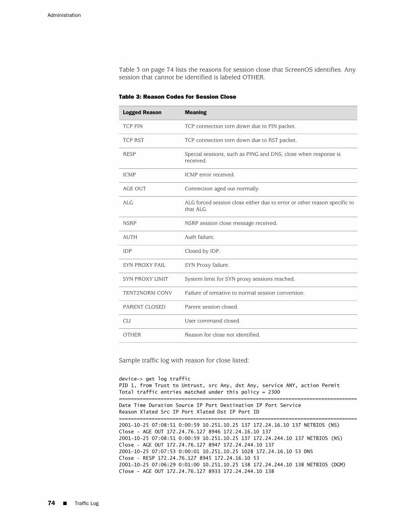
Table 3 on page 74 lists the reasons for session close that ScreenOS identifies. Anysession that cannot be identified is labeled OTHER.
Table 3: Reason Codes for Session Close
MeaningLogged Reason
TCP connection torn down due to FIN packet.TCP FIN
TCP connection torn down due to RST packet.TCP RST
Special sessions, such as PING and DNS, close when response isreceived.
RESP
ICMP error received.ICMP
Connection aged out normally.AGE OUT
ALG forced session close either due to error or other reason specific tothat ALG.
ALG
NSRP session close message received.NSRP
Auth failure.AUTH
Closed by IDP.IDP
SYN Proxy failure.SYN PROXY FAIL
System limit for SYN proxy sessions reached.SYN PROXY LIMIT
Failure of tentative to normal session conversion.TENT2NORM CONV
Parent session closed.PARENT CLOSED
User command closed.CLI
Reason for close not identified.OTHER
Sample traffic log with reason for close listed:
device-> get log trafficPID 1, from Trust to Untrust, src Any, dst Any, service ANY, action PermitTotal traffic entries matched under this policy = 2300================================================================================Date Time Duration Source IP Port Destination IP Port ServiceReason Xlated Src IP Port Xlated Dst IP Port ID================================================================================2001-10-25 07:08:51 0:00:59 10.251.10.25 137 172.24.16.10 137 NETBIOS (NS)Close - AGE OUT 172.24.76.127 8946 172.24.16.10 1372001-10-25 07:08:51 0:00:59 10.251.10.25 137 172.24.244.10 137 NETBIOS (NS)Close - AGE OUT 172.24.76.127 8947 172.24.244.10 1372001-10-25 07:07:53 0:00:01 10.251.10.25 1028 172.24.16.10 53 DNSClose - RESP 172.24.76.127 8945 172.24.16.10 532001-10-25 07:06:29 0:01:00 10.251.10.25 138 172.24.244.10 138 NETBIOS (DGM)Close - AGE OUT 172.24.76.127 8933 172.24.244.10 138
74 ■ Traffic Log
Administration

2001-10-25 07:06:11 0:03:16 10.251.10.25 2699 172.24.60.32 1357 TCP PORT 1357Close - TCP FIN 172.24.76.127 8921 172.24.60.32 1357
Sample traffic log without reason for close listed:
device-> get log trafficPID 1, from Trust to Untrust, src Any, dst Any, service HTTP, action PermitTotal traffic entries matched under this policy = 1538================================================================================Date Time Duration Source IP Port Destination IP Port ServiceXlated Src IP Port Xlated Dst IP Port ID================================================================================2002-07-19 15:53:11 0:01:33 10.251.10.25 2712 207.17.137.108 80 HTTP10.251.10.25 2712 207.17.137.108 802002-07-19 15:51:33 0:00:12 10.251.10.25 2711 66.163.175.128 80 HTTP10.251.10.25 2711 66.163.175.128 802002-07-19 15:41:33 0:00:12 10.251.10.25 2688 66.163.175.128 80 HTTP10.251.10.25 2688 66.163.175.128 802002-07-19 15:31:39 0:00:18 10.251.10.25 2678 66.163.175.128 80 HTTP10.251.10.25 2678 66.163.175.128 80
In the following example, you configure the device to not display the reason forclosing sessions because it interferes with a script that you want to run on the trafficlog. You must use the command line interface to change the log output style.
WebUI
Not available.
CLI
set log traffic detail 0save
Self Log
ScreenOS provides a self log to monitor and record all packets terminated at thesecurity device. For example, if you disable some management options on aninterface—such as WebUI, SNMP, and ping—and HTTP, SNMP, or ICMP traffic issent to that interface, entries appear in the self log for each dropped packet.
To activate the self log, do one of the following:
WebUI
Configuration > Report Settings > Log Settings: Select the Log Packets Terminatedto Self check box, then click Apply.
CLI
set firewall log-self
Self Log ■ 75
Chapter 2: Monitoring Security Devices
When you enable the self log, the security device logs the entries in two places: theself log and the traffic log. Similar to the traffic log, the self log displays the date,time, source address/port, destination address/port, duration, and service for eachdropped packet terminating at the security device. Self log entries typically have asource zone of Null and a destination zone of “self.”
Viewing the Self Log
You can view the self log, which is stored in flash storage on the security device,through either the CLI or WebUI.
WebUI
Reports > System Log > Self
CLI
get log self
Sorting and Filtering the Self Log
Similar to the event and traffic logs, when you use the CLI to view the self log, youcan sort or filter the log entries according to the following criteria:
■ Source or Destination IP Address: You can sort the self log by source ordestination IP address. You can also filter the self log by specifying a source ordestination IP address or range of addresses.
■ Date: You can sort the self log by date only, or by date and time. The device liststhe log entries in descending order by date and time.
You can also filter self log entries by specifying a start date, an end date, or adate range. When you specify a start date, the device displays log entries withdate/time stamps after the start date. When you specify an end date, the devicedisplays log entries with date/time stamps before the end date.
■ Time: When you sort the self log by time, the security device displays the logentries in descending order by time, regardless of the date. When you specify astart time, the device displays log entries with time stamps after the specifiedstart time, regardless of the date. When you specify an end time, the devicedisplays log entries with time stamps before the specified end time, regardlessof the date. When you specify both a start and end time, the device displays logentries with time stamps within the specified time period.
Example: Filtering the Self Log by Time
In this example, you filter self log entries by the end time. The security device displayslog entries with time stamps before the specified end time:
76 ■ Self Log
Administration
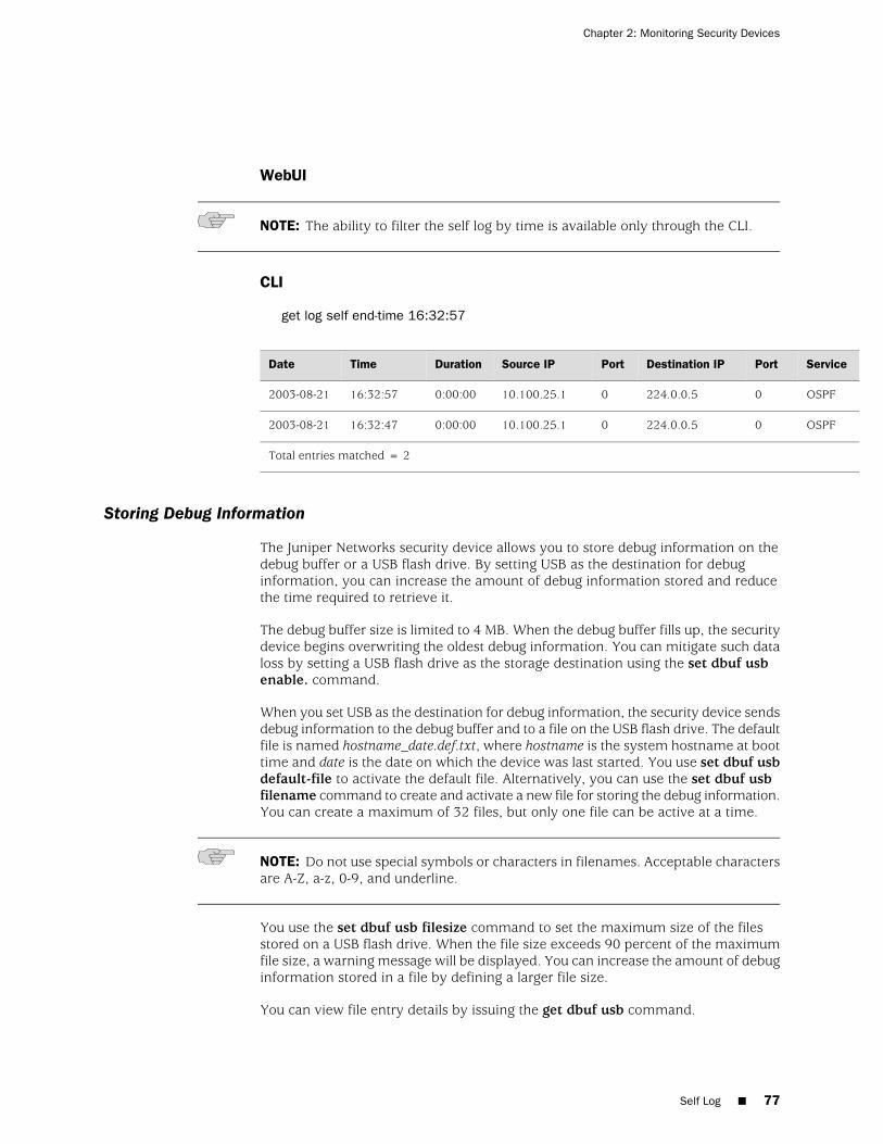
WebUI
NOTE: The ability to filter the self log by time is available only through the CLI.
CLI
get log self end-time 16:32:57
ServicePortDestination IPPortSource IPDurationTimeDate
OSPF0224.0.0.5010.100.25.10:00:0016:32:572003-08-21
OSPF0224.0.0.5010.100.25.10:00:0016:32:472003-08-21
Total entries matched = 2
Storing Debug Information
The Juniper Networks security device allows you to store debug information on thedebug buffer or a USB flash drive. By setting USB as the destination for debuginformation, you can increase the amount of debug information stored and reducethe time required to retrieve it.
The debug buffer size is limited to 4 MB. When the debug buffer fills up, the securitydevice begins overwriting the oldest debug information. You can mitigate such dataloss by setting a USB flash drive as the storage destination using the set dbuf usbenable. command.
When you set USB as the destination for debug information, the security device sendsdebug information to the debug buffer and to a file on the USB flash drive. The defaultfile is named hostname_date.def.txt, where hostname is the system hostname at boottime and date is the date on which the device was last started. You use set dbuf usbdefault-file to activate the default file. Alternatively, you can use the set dbuf usbfilename command to create and activate a new file for storing the debug information.You can create a maximum of 32 files, but only one file can be active at a time.
NOTE: Do not use special symbols or characters in filenames. Acceptable charactersare A-Z, a-z, 0-9, and underline.
You use the set dbuf usb filesize command to set the maximum size of the filesstored on a USB flash drive. When the file size exceeds 90 percent of the maximumfile size, a warning message will be displayed. You can increase the amount of debuginformation stored in a file by defining a larger file size.
You can view file entry details by issuing the get dbuf usb command.
Self Log ■ 77
Chapter 2: Monitoring Security Devices

Downloading the Self Log
You can also save the log as a text file to a location you specify, and then use anASCII text editor (such as Notepad or WordPad) to view it.
In this example, you download a self log to the local directory “C:\netscreen\logs”(WebUI) or to the root directory of a TFTP server at the IP address 10.1.1.5 (CLI).You name the file “self_log07-03-02.txt.”
WebUI
1. Reports > System Log > Self: Click Save.
The File Download dialog box prompts you to open the file (using an ASCII editor)or save it to disk.
2. Select the Save option, then click OK.
The File Download dialog box prompts you to choose a directory.
3. Specify C:\netscreen\logs, name the file self_log07-03-02.txt, then click Save.
CLI
get log self > tftp 10.1.1.5 self_log07-03-02.txt
Downloading the Asset Recovery Log
A Juniper Networks security device provides an asset recovery log to displayinformation about each time the device is returned to its default settings using theasset recovery procedure (see “Resetting the Device to the Factory Default Settings”on page 48). In addition to viewing the asset recovery log through the WebUI or CLI,you can also open or save the file to the location you specify. Use an ASCII text editor(such as Notepad) to view the file.
In this example, you download the asset recovery log to the local directory“C:\netscreen\logs” (WebUI) or to the root directory of a TFTP server at the IP address10.1.1.5 (CLI). You name the file “sys_rst.txt,”
WebUI
1. Reports > System Log > Asset Recovery: Click Save.
The File Download dialog box prompts you to open the file (using an ASCII editor)or save it to disk.
2. Select the Save option, then click OK.
The File Download dialog box prompts you to choose a directory.
3. Specify C:\netscreen\logs, name the file sys_rst.txt, then click Save.
78 ■ Downloading the Asset Recovery Log
Administration
CLI
get log asset-recovery > tftp 10.1.1.5 sys_rst.txt
Traffic Alarms
The security device supports traffic alarms when traffic exceeds thresholds that youhave defined in policies. You can configure the security device to alert you throughone or more of the following methods whenever the security device generates atraffic alarm:
■ Console
■ Internal (Event Log)
■ SNMP
■ Syslog
■ WebTrends
■ NetScreen-Global PRO
You set alarm thresholds to detect anomalous activity. To know what constitutesanomalous activity, you must first establish a baseline of normal activity. To createsuch a baseline for network traffic, you must observe traffic patterns over a periodof time. Then, after you have determined the amount of traffic that you consider asnormal, you can set alarm thresholds above that amount. Traffic exceeding thatthreshold triggers an alarm to call your attention to a deviation from the baseline.You can then evaluate the situation to determine what caused the deviation andwhether you need to take action in response.
You can also use traffic alarms to provide policy-based intrusion detection andnotification of a compromised system. Examples of the use of traffic alarms for thesepurposes are provided below.
Example: Policy-Based Intrusion Detection
In this example, there is a Web server with IP address 211.20.1.5 (and name “web1”)in the DMZ zone. You want to detect any attempts from the Untrust zone to accessthis Web server with Telnet. To accomplish this, you create a policy denying Telnettraffic from any address in the Untrust zone destined to the Web server named web1in the DMZ zone, and you set a traffic alarm threshold at 64 bytes. Because thesmallest size of IP packet is 64 bytes, even one Telnet packet attempting to reachthe Web server from the Untrust zone will trigger an alarm.
WebUI
Policy > Policy Elements > Addresses > List > New: Enter the following, then clickOK:
Traffic Alarms ■ 79
Chapter 2: Monitoring Security Devices
Address Name: web1IP Address/Domain Name: IP/Netmask: (select), 211.20.1.5/32Zone: DMZ
Policies > (From: Untrust, To: DMZ) New: Enter the following, then click OK:
Source Address: Address Book Entry: (select), AnyDestination Address: Address Book Entry: (select), web1Service: TelnetAction: Deny
> Advanced: Enter the following, then click Return to set the advanced options andreturn to the basic configuration page:
Counting: (select)Alarm Threshold: 64 Bytes/Sec, 0 Kbytes/Min
CLI
set address dmz web1 211.20.1.5/32set policy from untrust to dmz any web1 telnet deny count alarm 64 0save
Example: Compromised System Notification
In this example, you use traffic alarms to provide notification of a compromisedsystem. You have an FTP server with IP address 211.20.1.10 (and name ftp1) in theDMZ zone. You want to allow FTP-get traffic to reach this server. You don’t wanttraffic of any kind to originate from the FTP server. The occurrence of such trafficwould indicate that the system has been compromised, perhaps by a virus similarto the NIMDA virus. You define an address for the FTP server in the Global zone, sothat you can then create two global policies.
WebUI
Policy > Policy Elements > Addresses > List > New: Enter the following, then clickOK:
Address Name: ftp1IP Address/Domain Name: IP/Netmask: (select), 211.20.1.10/32Zone: Global
Policies > (From: Global, To: Global) New: Enter the following, then click OK:
Source Address: Address Book Entry: (select), AnyDestination Address: Address Book Entry: (select), ftp1Service: FTP-GetAction: Permit
80 ■ Traffic Alarms
Administration
Policies > (From: Global, To: Global) New: Enter the following, then click OK:
Source Address: Address Book Entry: (select), ftp1Destination Address: Address Book Entry: (select), AnyService: ANYAction: Deny
> Advanced: Enter the following, then click Return to set the advanced options andreturn to the basic configuration page:
Counting: (select)Alarm Threshold: 64 Bytes/Sec, 0 Kbytes/Min
CLI
set address global ftp1 211.20.1.10/32set policy global any ftp1 ftp-get permitset policy global ftp1 any deny count alarm 64 0save
Example: Sending Email Alerts
In this example, you set up notification by email alerts when there is an alarm. Themail server is at 172.16.10.254, the first email address to be notified [email protected], and the second address is [email protected]. The securitydevice includes traffic logs with event logs sent with email.
WebUI
Configuration > Report Settings > Email: Enter the following information, then clickApply:
Enable E-Mail Notification for Alarms: (select)Include Traffic Log: (select) SMTP Server Name: 172.16.10.254E-Mail Address 1: [email protected] Address 2: [email protected]
NOTE: If you have DNS enabled, you can also use a hostname for the mail server,such as mail.juniper.net.
CLI
set admin mail alertset admin mail mail-addr1 [email protected] admin mail mail-addr2 [email protected] admin mail server-name 172.16.10.254set admin mail traffic-logsave
Traffic Alarms ■ 81
Chapter 2: Monitoring Security Devices
Security Alarms and Audit Logs
Juniper Networks security devices enable you to configure automatic security alarms.When the security device detects a security violation (event), it alerts the networksecurity administrator and the users in the network with a security alarm. The securityalarm is displayed on the console.
NOTE: You need to have security administrator privileges to configure and monitorsecurity alarms and audit logs.
The security device provides an auditable event log for monitoring all security events.An audit log records the following elements for each event:
■ Date and time the audit log was generated
■ Module that generated the audit log
■ Severity level of the event
■ Type of the event
■ Detailed description of each security alarm event
■ Acknowledgment ID (unique)
■ ID of the authenticated user
■ Source IP address
■ Destination IP address and port number
■ Exclude rule ID
ScreenOS supports persistent storage mechanisms such as the syslog server, whichstores all audit logson a remote server. You can also save the audit log files to anexternal storage device. For more information about external storage space, see“Storing Log Information” on page 65.
NOTE: For detailed information about the messages that appear in the audit log, seethe ScreenOS Message Log Reference Guide.
Enabling Security Alarms
You can configure the security device to generate an automatic alarm when it detectsa security violation.
To log all alarms that a security device receives, you must enable the security alarmoption. You can enable security alarms through the WebUI or the CLI.
82 ■ Security Alarms and Audit Logs
Administration
WebUI
Configuration > Admin > Audit Setting: Enter the following, then click Apply:
Enable Alarm Security: (select)
CLI
set alarm security enable
In addition to enabling security alerts, you can configure the security device to sendaudible security alarms at regular intervals.
■ Audible Alarms—The security device displays security alarm messages onconsoles with an audible bell sound. The audible message is displayed on consolesthat are logged in, logging out, or logging into the network when the admin isacknowledging the security alarm.
■ Local-force—By default, the audible security alarm is visible to a local systemonly if the security administrator has logged in. By enabling the local-force feature,the security device displays the security alarm on a local system regardless ofwhether a security administrator is logged in or not.
■ Alarm Interval—The security device sends the audible alert message at regularintervals. The default interval is 10 seconds. You can set a maximum interval of3600 seconds.
■ Alarm Overwrite—The maximum number of alarm events the security devicecan store is 100. When a new alarm event occurs, the security device drops thenewest security alarm by default. However, you can configure the security deviceto overwrite the oldest event in the log with the new event.
WebUI
Configuration > Admin > Audit Setting: Enter the following, then click Apply:
Use Alarm Security Audible: (select)Use Alarm Security Local-Force: (select)Use Alarm Security Overwrite: (select)Alarm Security Interval (seconds): 10
CLI
set alarm security audibleset alarm security local-forceunset alarm security overwrite disableset alarm security interval number
Viewing Security Alarms
You can use the following CLI commands to view the details of a single security alarmand statistics for all security alarms.
Security Alarms and Audit Logs ■ 83
Chapter 2: Monitoring Security Devices
CLI
To view the details of a security alarm:
get alarm security ack-id number
To view statistics for all security alarms:
get alarm security statistics
The output of the get alarm security command displays the following elements:
■ TOTAL—Total number of security alarms
■ ACTIVE—Number of security alarms currently not acknowledged
■ ACKED—Number of security alarms manually acknowledged by the securityadministrator
■ AUTO ACKED—Number of security alarms auto-acknowledged
■ OVERWRITTEN—Number of security alarms overwritten by new events
■ LOG EXCLUDED—Number of security alarms excluded by the exclude rules
Acknowledging Security Alarms
When a security alarm is triggered, you can execute the exec alarm securitycommand to acknowledge it:
exec alarm security ack-id number
All consoles—connected to the network—then display the acknowledged securityalarm, and the alarm status becomes inactive. Once the security alarm isacknowledged (manually or automatically), it becomes inactive and an audit log isgenerated. The security administrator can retrieve the details of each acknowledgedsecurity alarm from the audit log.
You can use the exec alarm security all command to acknowledge all active securityalarms.
exec alarm security all
Setting Potential-Violation Security Alarms
Juniper Networks security devices enable you to configure a set of rules for monitoringevents, including thresholds for each event type. If any of the rules is violated, thesecurity device triggers a potential-violation security alarm.
A potential-violation security alarm is triggered if any of the following events exceedsits threshold value:
■ Authentication violations
■ Policy violations
84 ■ Security Alarms and Audit Logs
Administration
■ Replays of security attributes
■ Encryption failures
■ Decryption failures
■ Key-generation failures
■ Cryptographic and noncryptographic module self-test failures
■ Internet Key Exchange (IKE) Phase 1 authentication failures
■ IKE Phase 2 authentication failures
Once an event exceeds its threshold value, the security device triggers apotential-violation security alarm. The default threshold value is 3 for any event.
NOTE: The potential-violation security alarm does not support IPv6 traffic.
Example: Configuring a Device to Trigger a Potential-Violation Alarm
In this example, you configure the security device to trigger an alarm when thenumber of encryption, decryption, and IKE Phase 1/Phase 2 failures exceeds thepotential-violation threshold value of 5. You also configure the security device totrigger an alarm when the number of policy failures exceeds 5 per minute.
When any of these threshold values is exceeded, the security device triggers a securityalarm and alerts the security administrator.
NOTE: You must use the CLI to configure potential-violation security alarms.
CLI
set alarm security potential-violation encryption-failures 5 set alarm security potential-violation decryption-failures 5 set alarm security potential-violation ike-p1-failures 5 set alarm security potential-violation ike-p2-failures 5 set alarm security potential-violation policy-violation rate 5 per minute save
For more information about potential-violation commands, see the ScreenOS CLIReference Guide: IPv4 Command Descriptions.
Configuring Exclude Rules
You can set rules to exclude some audit logs from being generated. You must havesecurity administrator privileges to include or exclude auditable events from the auditlog.
You can configure exclude rules based on the following attributes:
Security Alarms and Audit Logs ■ 85
Chapter 2: Monitoring Security Devices
■ Exclude ID—Identity of the exclude rule
■ User ID—Identity of the authenticated user
■ Event Type—Log type or event type
■ Network Addresses—Source IP address, destination IP address, and destinationport
By default, no exclude rule is set and the security device generates all logs. Youcannot set more than 10 exclude rules. However, you can modify the existing rulesaccording to the requirements of your network. Excluded security alarms are notgenerated in the audit log.
Example: Setting an Exclude Rule to Exclude an Event for the Audit Log
In this example, you—as the root admin—configure an exclude rule to prevent afailure event from being generated in the audit log.
You can use the WebUI or the CLI to configure an exclude rule.
WebUI
Configuration > Admin > Exclude Rules: Enter the following, then click Add:
Rule ID: 1User ID: adminEvent Type: 2Source IP address: 2.2.2.0Destination IP Address: 3.3.3.0Destination Port: 80Event Result: Failure (select)
The Configured Exclude Rules table displays all exclude rules configured on thesecurity device.
CLI
set log exclude-id 1 user-id sam event-type 2 src-ip 2.2.2.0 dst-ip 3.3.3.0 dst-port 80 failure
To view the configured exclude rules:
get log exclude
The security device displays all active exclude rules that you have configured.
Syslog
A security device can generate syslog messages for system events at predefinedseverity levels (see the list of severity levels in “Syslog” on page 86) and, optionally,for traffic that policies permit across a firewall. It sends these messages to up to four
86 ■ Syslog
Administration
designated syslog hosts running on UNIX and Linux systems. For each syslog host,you can specify the following:
■ Whether the security device includes traffic log entries or event log entries, orboth.
■ Whether to send traffic through a VPN tunnel to the syslog server and—if througha VPN tunnel—which interface to use as the source interface (see “Example:Self-Generated Traffic Through a Route-Based Tunnel” on page 102 and “Example:Self-Generated Traffic Through a Policy-Based Tunnel” on page 109).
■ The port to which the security device sends syslog messages.
■ The security facility, which classifies and sends emergency and alert levelmessages to the syslog host; and the regular facility, which classifies and sendsall other messages for events unrelated to security.
By default, the security device sends messages to syslog hosts with User DatagramProtocol (UDP) on port 514. To increase the reliability of the message delivery, youcan change the transport protocol for each syslog host to Transmission ControlProtocol (TCP) on port 514.
You can use syslog messages to create email alerts for the system administrator orto display messages on the console of the designated host using UNIX syslogconventions.
NOTE: On UNIX and Linux platforms, modify the /etc/rc.d/init.d/syslog file so thatthe syslog retrieves information from the remote source (syslog -r).
Enabling Syslog on Backup Devices
In an Active/Passive NSRP configuration where one device acts as a primary and theother as its backup, only the primary device sends all the syslog messages to thesyslog server. Whereas the backup devices in an NSRP cluster send only the eventlog messages. To allow an administrator to effectively monitor the backup devices,all the syslog messages need to be backed up on the syslog server. Hence in thecurrent release, ScreenOS allows you to configure the backup devices to send all thesyslog messages to the syslog server. This configuration is synced to the primarydevice in an NSRP Active/Passive cluster. You can verify the status of the syslogbackup on a backup device by issuing the CLI command get syslog backup. Bydefault, syslog backup is disabled.
To enable the backup device to send all the syslog messages:
WebUI
Configuration > Report Settings > Syslog: Enter the following, then click Apply:
Enable syslog backup: Select this option to send logs from the backup device to the specified syslog servers.
Syslog ■ 87
Chapter 2: Monitoring Security Devices
CLI
set syslog backup enablesave
Example: Enabling Multiple Syslog Servers
In this example, you configure the security device to send event and traffic logs withTCP to three syslog servers at the following IP addresses/port numbers:
■ 1.1.1.1/1514
■ 2.2.2.1/2514
■ 3.3.3.1/3514
You set both the security and facility levels to Local0.
WebUI
Configuration > Report Settings > Syslog: Enter the following, then click Apply:
Enable syslog messages: Select this option to send logs to the specified syslog servers.No.: Select 1, 2, and 3 to indicate you are adding 3 syslog servers. IP/Hostname: 1.1.1.1, 2.2.2.1, 3.3.3.1Port: 1514, 2514, 3514 Security Facility: Local0, Local0, Local0Facility: Local0, Local0, Local0Event Log: (select)Traffic Log: (select)TCP: (select)
CLI
set syslog config 1.1.1.1 port 1514set syslog config 1.1.1.1 log allset syslog config 1.1.1.1 facilities local0 local0set syslog config 1.1.1.1 transport tcpset syslog config 2.2.2.1 port 2514set syslog config 2.2.2.1 log allset syslog config 2.2.2.1 facilities local0 local0set syslog config 2.2.2.1 transport tcpset syslog config 3.3.3.1 port 3514set syslog config 3.3.3.1 log allset syslog config 3.3.3.1 facilities local0 local0set syslog config 2.2.2.1 transport tcpset syslog enablesave
88 ■ Syslog
Administration
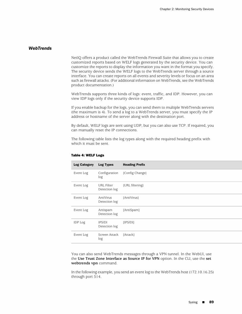
WebTrends
NetIQ offers a product called the WebTrends Firewall Suite that allows you to createcustomized reports based on WELF logs generated by the security device. You cancustomize the reports to display the information you want in the format you specify.The security device sends the WELF logs to the WebTrends server through a sourceinterface. You can create reports on all events and severity levels or focus on an areasuch as firewall attacks. (For additional information on WebTrends, see the WebTrendsproduct documentation.)
WebTrends supports three kinds of logs: event, traffic, and IDP. However, you canview IDP logs only if the security device supports IDP.
If you enable backup for the logs, you can send them to multiple WebTrends servers(the maximum is 4). To send a log to a WebTrends server, you must specify the IPaddress or hostname of the server along with the destination port.
By default, WELF logs are sent using UDP, but you can also use TCP. If required, youcan manually reset the IP connections.
The following table lists the log types along with the required heading prefix withwhich it must be sent.
Table 4: WELF Logs
Heading PrefixLog TypesLog Category
[Config Change]Configurationlog
Event Log
[URL filtering]URL FilterDetection log
Event Log
[AntiVirus]AntiVirusDetection log
Event Log
[AntiSpam]AntispamDetection log
Event Log
[IPS/DI]IPS/DIDetection log
IDP Log
[Attack]Screen Attacklog
Event Log
You can also send WebTrends messages through a VPN tunnel. In the WebUI, usethe Use Trust Zone Interface as Source IP for VPN option. In the CLI, use the setwebtrends vpn command.
In the following example, you send an event log to the WebTrends host (172.10.16.25)through port 514.
Syslog ■ 89
Chapter 2: Monitoring Security Devices
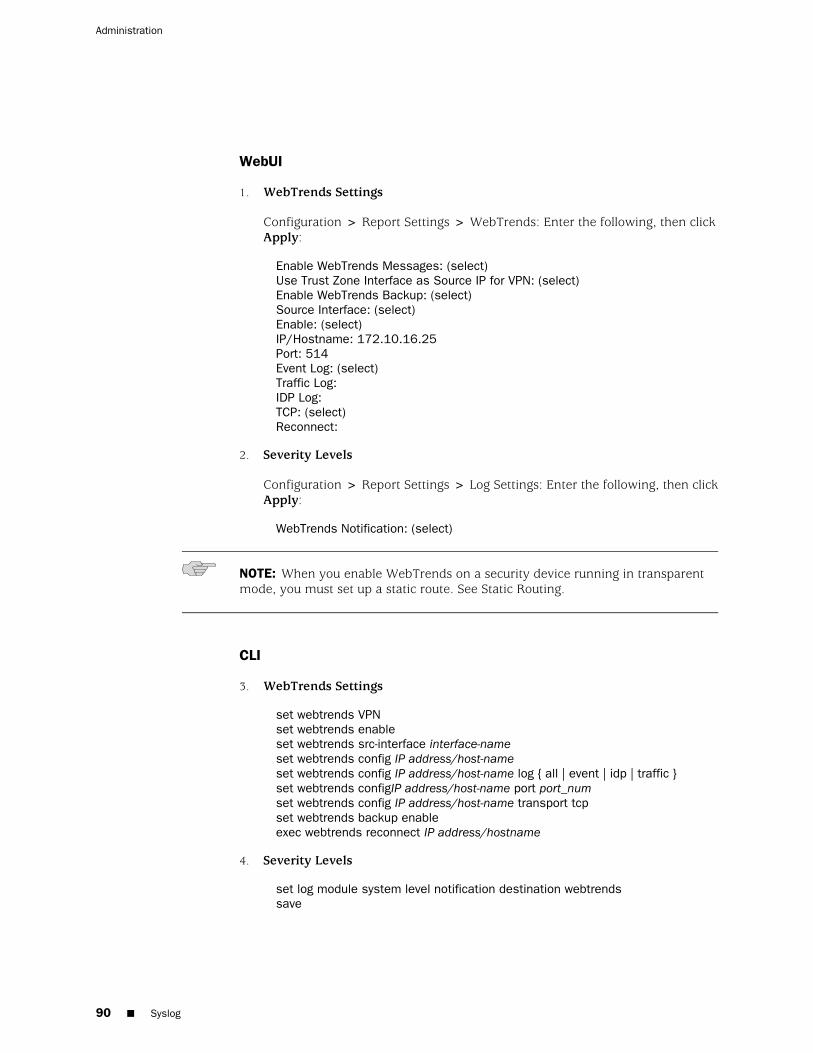
WebUI
1. WebTrends Settings
Configuration > Report Settings > WebTrends: Enter the following, then clickApply:
Enable WebTrends Messages: (select)Use Trust Zone Interface as Source IP for VPN: (select)Enable WebTrends Backup: (select)Source Interface: (select)Enable: (select)IP/Hostname: 172.10.16.25Port: 514Event Log: (select)Traffic Log:IDP Log:TCP: (select)Reconnect:
2. Severity Levels
Configuration > Report Settings > Log Settings: Enter the following, then clickApply:
WebTrends Notification: (select)
NOTE: When you enable WebTrends on a security device running in transparentmode, you must set up a static route. See Static Routing.
CLI
3. WebTrends Settings
set webtrends VPNset webtrends enableset webtrends src-interface interface-nameset webtrends config IP address/host-nameset webtrends config IP address/host-name log { all | event | idp | traffic }set webtrends configIP address/host-name port port_numset webtrends config IP address/host-name transport tcpset webtrends backup enableexec webtrends reconnect IP address/hostname
4. Severity Levels
set log module system level notification destination webtrendssave
90 ■ Syslog
Administration
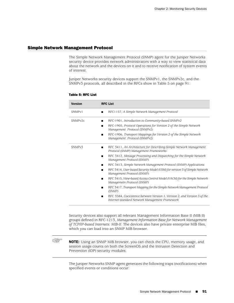
Simple Network Management Protocol
The Simple Network Management Protocol (SNMP) agent for the Juniper Networkssecurity device provides network administrators with a way to view statistical dataabout the network and the devices on it and to receive notification of system eventsof interest.
Juniper Networks security devices support the SNMPv1, the SNMPv2c, and theSNMPv3 protocols, all described in the RFCs show in Table 5 on page 91:
Table 5: RFC List
RFC ListVersion
■ RFC1157, A Simple Network Management ProtocolSNMPv1
■ RFC-1901, Introduction to Community-based SNMPv2
■ RFC-1905, Protocol Operations for Version 2 of the Simple NetworkManagement Protocol (SNMPv2)
■ RFC-1906, Transport Mappings for Version 2 of the Simple NetworkManagement Protocol (SNMPv2)
SNMPv2c
■ RFC 3411, An Architecture for Describing Simple Network ManagementProtocol (SNMP) Management Frameworks
■ RFC 3412, Message Processing and Dispatching for the Simple NetworkManagement Protocol (SNMP)
■ RFC 3413, Simple Network Management Protocol (SNMP) Applications
■ RFC 3414, User-based Security Model (USM) for version 3 of Simple NetworkManagement Protocol (SNMP)
■ RFC 3415, View-based Access Control Model (VACM) for the Simple NetworkManagemetn Protocol (SNMP)
■ RFC 3417, Transport Mapping for the Simple Network Management Protocol(SNMP)
■ RFC 3584, Coexistence between Version 1, Version 2, and Version 3 of theInternet-standard Network Management Framework
SNMPv3
Security devices also support all relevant Management Information Base II (MIB II)groups defined in RFC-1213, Management Information Base for Network Managementof TCP/IP-based Internets: MIB-II. The devices also have private enterprise MIB files,which you can load into an SNMP MIB browser.
NOTE: Using an SNMP MIB browser, you can check the CPU, memory usage, andsession usage counts on both the ScreenOS and the Intrusion Detection andPrevention (IDP) security modules.
The Juniper Networks SNMP agent generates the following traps (notifications) whenspecified events or conditions occur:
Simple Network Management Protocol ■ 91
Chapter 2: Monitoring Security Devices
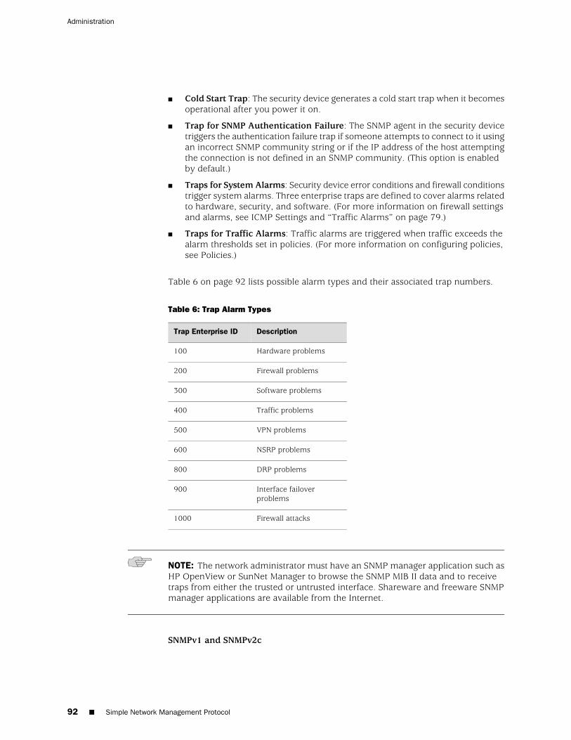
■ Cold Start Trap: The security device generates a cold start trap when it becomesoperational after you power it on.
■ Trap for SNMP Authentication Failure: The SNMP agent in the security devicetriggers the authentication failure trap if someone attempts to connect to it usingan incorrect SNMP community string or if the IP address of the host attemptingthe connection is not defined in an SNMP community. (This option is enabledby default.)
■ Traps for System Alarms: Security device error conditions and firewall conditionstrigger system alarms. Three enterprise traps are defined to cover alarms relatedto hardware, security, and software. (For more information on firewall settingsand alarms, see ICMP Settings and “Traffic Alarms” on page 79.)
■ Traps for Traffic Alarms: Traffic alarms are triggered when traffic exceeds thealarm thresholds set in policies. (For more information on configuring policies,see Policies.)
Table 6 on page 92 lists possible alarm types and their associated trap numbers.
Table 6: Trap Alarm Types
DescriptionTrap Enterprise ID
Hardware problems100
Firewall problems200
Software problems300
Traffic problems400
VPN problems500
NSRP problems600
DRP problems800
Interface failoverproblems
900
Firewall attacks1000
NOTE: The network administrator must have an SNMP manager application such asHP OpenView or SunNet Manager to browse the SNMP MIB II data and to receivetraps from either the trusted or untrusted interface. Shareware and freeware SNMPmanager applications are available from the Internet.
SNMPv1 and SNMPv2c
92 ■ Simple Network Management Protocol
Administration

Security devices are not shipped with a default configuration for the SNMP manager.To configure your security device for SNMP, you must first create communities,define their associated hosts, and assign permissions (read/write or read-only).
When you create an SNMP community, you can specify whether the communitysupports SNMPv1, SNMPv2c, or both SNMP versions, as required by the SNMPmanagement stations. (For backward compatibility with earlier ScreenOS releasesthat only support SNMPv1, security devices support SNMPv1 by default.) If an SNMPcommunity supports both SNMP versions, you must specify a trap version for eachcommunity member.
For security reasons, an SNMP community member with read/write privileges canchange only the following variables on a security device:
■ sysContact—Contact information for the security device admin in the event thatthe SNMP admin needs to contact the admin for the security device. This canbe the security admin’s name, email address, telephone number, office location,or a combination of such information.
■ sysLocation—The physical location of the security device. This can be the nameof a country, city, building, or its exact location on a rack in a network operationscenter (NOC).
■ sysName—The name that SNMP administrators use for the security device. Byconvention, this is a fully qualified domain name (FQDN), but it can be somethingelse.
■ snmpEnableAuthenTraps—This enables or disables the ability of the SNMPagent in the security device to generate a trap whenever someone attempts tocontact the SNMP agent with an incorrect SNMP community name.
■ ipDefaultTTL—The default value inserted into the time-to-live (TTL) field in theIP header of datagrams originating from the security device whenever theTransport Layer protocol does not supply a TTL value.
■ ipForwarding—This indicates whether or not the security device forwardstraffic—other than that destined for the security device itself. By default, thesecurity device indicates that it does not forward traffic.
SNMPv3
Security devices are not shipped with a default configuration for SNMPv3. To configureyour security device for SNMPv3 , you must first create a unique engine ID to identifyan SNMP entity and a user-based security model (USM) with the respective privilegeand password.
When you create a USM user, you can specify the authentication type (MD5, SHA,or None). The authentication type is used to compute identical message digests forthe same block of data. It requires a password and uses Data Encryption Standard(DES) to encrypt and decrypt the SNMPv3 packets.
SNMPv1 and SNMPv2c Implementation Overview
Juniper Networks has implemented SNMP in its devices in the following ways:
Simple Network Management Protocol ■ 93
Chapter 2: Monitoring Security Devices
■ SNMP administrators are grouped in SNMP communities. A device can supportup to three communities, with up to eight members in each community.
■ A community member can be either a single host or a subnet of hosts, dependingon the netmask you use when defining the member. By default, the securitydevice assigns an SNMP community member with a 32-bit netmask(255.255.255.255), which defines it as a single host.
■ If you define an SNMP community member as a subnet, any device on thatsubnet can poll the security device for SNMP MIB information. However, thesecurity device cannot send an SNMP trap to a subnet, only to an individual host.
■ Each community has either read-only or read/write permission for the MIB IIdata.
■ Each community can support SNMPv1, SNMPv2c, or both. If a communitysupports both versions of SNMP, you must specify a trap version for eachcommunity member.
■ You can allow or deny receipt of traps for each community.
■ You can access the MIB II data and traps through any physical interface.
■ Each system alarm (a system event classified with a severity level of critical,alert, or emergency) generates a single enterprise SNMP trap to each of the hostsin each community that is set to receive traps.
■ The security device sends Cold Start/Link Up/Link Down traps to all hosts incommunities that you set to receive traps.
■ If you specify trap-on for a community, you also have the option to allow trafficalarms.
■ You can send SNMP messages through a route-based or policy-based VPN tunnel.For more information, see “Configuring a MIB Filter in the SNMP Community”on page 96.
SNMPv3 Implementation Overview
Juniper Networks has implemented SNMPv3 in its devices in the following ways:
■ An administrator can define a USM user in the SNMPv3 framework. A devicecan support up to 32 users.
■ The security device administrator can create the view-based access control model(VACM) views. Each view is tagged with an object identifier and mask values. Adevice can support up to 32 VACM views.
■ The security device administrator can create a VACM access group. For eachaccess group you can define the security model, security level, and the privilegeaccess. A device can support up to 32 VACM access groups.
■ The security device administrator can create a group to map an SNMPv3 USMuser, an SNMPv1 community, or an SNMPv2c community, in combination witha VACM access group.
■ The security device administrator can configure an SNMPv1 or SNMPv2ccommunity under an SNMPv3 framework. In an SNMPv3 community, theadministrator can enforce access control to SNMPv1 or SNMPv2c requests aswell. Each community has a tag name.
94 ■ Simple Network Management Protocol
Administration
■ The administrator can configure the trap details such as filters, target parameters,and target address.
■ The SNMPv3 filters are configured by an administrator. A device can support upto 32 SNMPv3 filters.
■ Each filter is attached to a target (host).
■ The target parameter is used when sending a trap to a target. The administratorcan configure an SNMPv3 target parameter. A device can support up to 32 targetparameters.
■ Each target has an IPv4 or IPv6 address/netmask.
■ You can enter both the IPv4 and IPv6 addresses. The system sends the trap tothe target if the mask is 32 for IPv4 addresses or 128 for IPv6 addresses.
■ Each target has a trap port and a tag.
■ You can specify 8 tags to a target.
Defining a Read/Write SNMP Community
In this example, you create an SNMP community named MAge11. You assign itread/write privileges and enable its members to receive MIB II data and traps. It hasthe members 1.1.1.5/32 and 1.1.1.6/32. Each of these members has an SNMPmanager application running a different version of SNMP: SNMPv1 and SNMPv2c.The community name functions as a password and needs to be protected.
You provide contact information for the local admin of the security device in casean SNMP community member needs to contact him—name: [email protected] also provide the location of the security device—location: 3-15-2. These numbersindicate that the device is on the third floor, in the fifteenth row, in the second positionin that row.
You also enable the SNMP agent to generate traps whenever someone illegallyattempts an SNMP connection to the security device. Authentication failure traps isa global setting that applies to all SNMP communities and is disabled by default.
Finally, you enable SNMP manageability on ethernet1, an interface that you havepreviously bound to the Trust zone. This is the interface through which the SNMPmanager application communicates with the SNMP agent in the security device.
WebUI
Configuration > Report Settings > SNMP: Enter the following settings, then clickApply:
System Contact: [email protected]: 3-15-2Enable Authentication Fail Trap: (select)
Configuration > Report Settings > SNMP > New Community: Enter the followingsettings, then click OK:
Community Name: MAge11
Simple Network Management Protocol ■ 95
Chapter 2: Monitoring Security Devices
Permissions:Write: (select)Trap: (select)Including Traffic Alarms: (clear)Version: ANY (select)Hosts IP Address/Netmask and Trap Version:1.1.1.5/32 v11.1.1.6/32 v2c
Network > Interfaces > Edit (for ethernet1): Enter the following settings, then clickOK:
Service Options:Management Services: SNMP
CLI
set snmp contact [email protected] snmp location 3-15-2set snmp auth-trap enableset snmp community MAge11 read-write trap-on version anyset snmp host Mage 1.1.1.5/32 trap v1set snmp host Mage 1.1.1.6/32 trap v2set interface ethernet1 manage snmpsave
Configuring a MIB Filter in the SNMP Community
An SNMP agent can encounter problems when different devices from the samemanagement domain report conflicting IP address ranges. This issue is widelyobserved in NAT deployments where the tendency is to use similar IP address rangesin the private domain. However, by configuring a MIB filter in the SNMP community,you can now resolve the issue of overlapping addresses by filtering conflicting privateIP addresses that exist in the same domain.
As root admin, you can configure the MIB filter to either include or exclude an IPaddress entry from the address list of the following MIB tables:
■ atTable
■ ipAddrTable
■ ipNetToMediaTable
■ ipRouteTable
When you configure the MIB filter to exclude an IP address, all IP addresses areincluded except the one being filtered. Likewise, if you configure the MIB filter toinclude an IP address, only the filtered address is included in the MIB table and allother IP addresses are excluded. Each MIB filter you configure should be bound toits related SNMP community.
96 ■ Simple Network Management Protocol
Administration
NOTE: You cannot configure a MIB filter to both include and exclude IP addressesat the same time.
Example
In this example, you (as the root admin) configure a MIB filter filter-private-addressto exclude private network IP addresses 192.168.0.0/16 and 10.10.0.0/16. The MIBfilter is bound to the SNMP community comm_vzband the SNMP host IP address is202.100.1.1/32.
You can use the WebUI and the CLI to create and bind a MIB filter to the SNMPcommunity.
WebUI
Configuration > Report Settings > SNMP > MIB Filter Edit: Enter the following,then click Apply:
MIB Filter Name: filter-private-addressType: IP (select)Action: Exclude (select)
Configuration > Report Settings > SNMP > MIB Filter Edit: Enter the following,then click Add:
IP: 192.168.0.0Netmask: 255.255.0.0IP: 10.10.0.0Netmask: 255.255.0.0
Configuration > Report Setting > SNMP > Community Edit: Enter the following,then click OK:
Community Name: comm_vzbPermission:Write: (select)Trap: (select)Including Traffic Alarms: (clear)Version: ANY (select)MIB Filter: filter_private_address (select)Host IP Address: 202.100.1.1Netmask: 255.255.255.255Trap: V2C
CLI
1. Creating a MIB Filter:
set snmp mib-filter name filter-private-address type ip action exclude
2. Adding an Entry to the MIB Filter:
Simple Network Management Protocol ■ 97
Chapter 2: Monitoring Security Devices
set snmp mib-filter filter-private-address ip 192.168.0.0/255.255.0.0set snmp mib-filter filter-private-address ip 10.10.0.0/255.255.0.0
3. Binding a MIB Filter to the SNMP Community:
set snmp community comm_vzb read-write version any set snmp community comm_vzb mib-filter filter-private-address
4. Assigning a Host to the SNMP Community:
set snmp host comm_vzb 202.100.1.1/255.255.255.255 trap v2save
Example: Configuring an SNMPv3 packet
In this example, you (as the root admin) configure an SNMPv3 packet.
WebUI
1. Engine-ID
NOTE: Local engine ID configuration is optional. A local-engine ID is to identify anSNMP entity. By default, the serial number of the device is assigned as the value ofthe local engine ID.
Configuration > Report Settings > SNMPv3: Enter the following settings, thenclick Apply:
Local-engine id: netscreen
2. USM User
Configuration > Report Settings > SNMPv3 > USM User > New User: Enterthe following settings, then click OK:
User Name: netscreenAuthentication Type: (select)Authentication Password: netscreenPrivacy Protocol: (select)Privacy Password: netscreen
3. View
Configuration > Report Settings > SNMPv3 > VACM > New View: Enter thefollowing settings, then click OK:
View Name: test-view
Configuration > Report Settings > SNMPv3 >VACM > View Databse Edit:Enter the following settings, then click Add:
Subtree OID: .1
98 ■ Simple Network Management Protocol
Administration
Subtree Mask: FFType: (select)
4. Access Group
Configuration > Report Settings > SNMPv3 >VACM > New Access Group:Enter the following settings, then click OK:
Group Name: test-grpSecurity Model: (select)Security Level: (select)Read View: (select)Write View: (select)Notification View: (select)
5. Group Mapping
Configuration > Report Settings > SNMPv3 > VACM > New Sec-to-groupMapping: Enter the following settings, then click OK:
Security Model: (select)User Name: (select)Community: (read only)Group Name: (select)
6. Community
NOTE: The community name must be unique.
Configuration > Report Settings > SNMPv3 > Community > New Community:Enter the following settings, then click OK:
Community Name: publicTag: public
7. Trap
Configuration > Report Settings > SNMPv3 >Trap > New Filter: Enter thefollowing settings, then click OK:
Filter Name: test-filter
Configuration > Report Settings > SNMPv3 > Trap > Filter Database Edit:Enter the following settings, then click Add:
Subtree OID: .1Subtree Mask: FFType: (select)
8. Target Parameter
Configuration > Report Settings > SNMPv3 > Trap > New Target Parameter:Enter the following settings, then click OK:
Simple Network Management Protocol ■ 99
Chapter 2: Monitoring Security Devices
Target Parameter Name: test-paramFilter Name: (select)Security Model: (select)Security Level: (select)User Name: (select)
9. Target Address
Configuration > Report Settings > SNMPv3 > Trap > New Target Address:Enter the following settings, then click OK:
Target Name: test-targetTarget IPv4 Address/Netmask: 192.168.1.1/32Trap Port: 162Target Parameter: (select)Taglist: (select)
CLI
1. Engine ID
set snmpv3 local-engine id netscreen
2. USM User
set snmpv3 user netscreen auth md5 auth-pass netscreen priv des priv-passnetscreen
3. View
set snmpv3 view name test-viewset snmpv3 view test-view oid .1 mask FF type include
4. Access Group
set snmpv3 access group test-grp sec-model usm sec-level priv read test-view
5. Group Mapping
set snmpv3 group-mapping sec-model usm user netscreen group test-grp
6. Community
set snmpv3 community public tag public
7. Trap
set snmpv3 filter name test-filterset snmpv3 filter test-filter oid .1 mask FF type include
8. Target Parameter
set snmpv3 target-param test-param filter test-filter sec-model usm sec-level privuser netscreen
100 ■ Simple Network Management Protocol
Administration
9. Target Address
set snmpv3 target test-target address 192.168.1.1/32 port 162 target-paramtest-param
VPN Tunnels for Self-Initiated Traffic
You can use virtual private network (VPN) tunnels to secure remote monitoring of asecurity device from a fixed IP address. Using a VPN tunnel, you can protect trafficaddressed to and initiated from a security device. Types of traffic initiated from asecurity device can include NetScreen-Global PRO reports, event log entries sent tosyslog and WebTrends servers, and SNMP MIB traps.
Juniper Networks security devices support two types of VPN tunnel configurations:
■ Route-Based VPNs: The security device uses route table entries to direct trafficto tunnel interfaces, which are bound to VPN tunnels.
To send traffic such as event log entries, NetScreen-Global PRO reports, or SNMPtraps generated by the security device through a route-based VPN tunnel, youmust manually enter a route to the proper destination. The route must point tothe tunnel interface that is bound to the VPN tunnel through which you want thesecurity device to direct the traffic. No policy is required.
■ Policy-Based VPNs: The security device uses the VPN tunnel names specificallyreferenced in policies to direct traffic through VPN tunnels.
To send self-initiated traffic through a policy-based VPN tunnel, you must includethe source and destination addresses in the policy. For the source address, usethe IP address of an interface on the security device. For the destination address,use the IP address of the storage server or SNMP community member’sworkstation, if it is located behind a remote security device. If the remote SNMPcommunity member uses the NetScreen-Remote VPN client to make VPNconnections to the local security device, use an internal IP address defined onthe NetScreen-Remote as the destination address.
If either the remote gateway or the end entity has a dynamically assigned IP address,then the security device cannot initiate the formation of a VPN tunnel because theseaddresses cannot be predetermined, and thus you cannot define routes to them. Insuch cases, the remote host must initiate the VPN connection. After either apolicy-based or route-based VPN tunnel is established, both ends of the tunnel caninitiate traffic if policies permit it. Also, for a route-based VPN, there must be a routeto the end entity through a tunnel interface bound to the VPN tunnel—either becauseyou manually entered the route or because the local security device received theroute through the exchange of dynamic routing messages after a tunnel wasestablished. (For information about dynamic routing protocols, see Routing.) Youcan also use VPN monitoring with the rekey option or IKE heartbeats to ensure thatonce the tunnel is established, it remains up regardless of VPN activity. (For moreinformation about these options, seeVPN Monitoring and Monitoring Mechanisms.)
For each VPN tunnel configuration type, you can use any of the following types ofVPN tunnel:
VPN Tunnels for Self-Initiated Traffic ■ 101
Chapter 2: Monitoring Security Devices
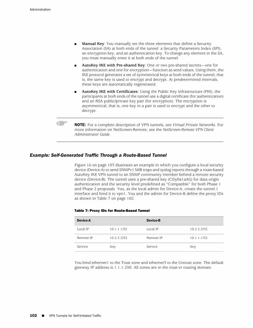
■ Manual Key: You manually set the three elements that define a SecurityAssociation (SA) at both ends of the tunnel: a Security Parameters Index (SPI),an encryption key, and an authentication key. To change any element in the SA,you must manually enter it at both ends of the tunnel.
■ AutoKey IKE with Pre-shared Key: One or two pre-shared secrets—one forauthentication and one for encryption—function as seed values. Using them, theIKE protocol generates a set of symmetrical keys at both ends of the tunnel; thatis, the same key is used to encrypt and decrypt. At predetermined intervals,these keys are automatically regenerated.
■ AutoKey IKE with Certificates: Using the Public Key Infrastructure (PKI), theparticipants at both ends of the tunnel use a digital certificate (for authentication)and an RSA public/private key pair (for encryption). The encryption isasymmetrical; that is, one key in a pair is used to encrypt and the other todecrypt.
NOTE: For a complete description of VPN tunnels, see Virtual Private Networks. Formore information on NetScreen-Remote, see the NetScreen-Remote VPN ClientAdministrator Guide.
Example: Self-Generated Traffic Through a Route-Based Tunnel
Figure 16 on page 103 illustrates an example in which you configure a local securitydevice (Device-A) to send SNMPv1 MIB traps and syslog reports through a route-basedAutoKey IKE VPN tunnel to an SNMP community member behind a remote securitydevice (Device-B). The tunnel uses a pre-shared key (Ci5y0a1aAG) for data originauthentication and the security level predefined as “Compatible” for both Phase 1and Phase 2 proposals. You, as the local admin for Device-A, create the tunnel.1interface and bind it to vpn1. You and the admin for Device-B define the proxy IDsas shown in Table 7 on page 102.
Table 7: Proxy IDs for Route-Based Tunnel
Device-BDevice-A
10.2.2.2/32Local IP10.1.1.1/32Local IP
10.1.1.1/32Remote IP10.2.2.2/32Remote IP
AnyServiceAnyService
You bind ethernet1 to the Trust zone and ethernet3 to the Untrust zone. The defaultgateway IP address is 1.1.1.250. All zones are in the trust-vr routing domain.
102 ■ VPN Tunnels for Self-Initiated Traffic
Administration
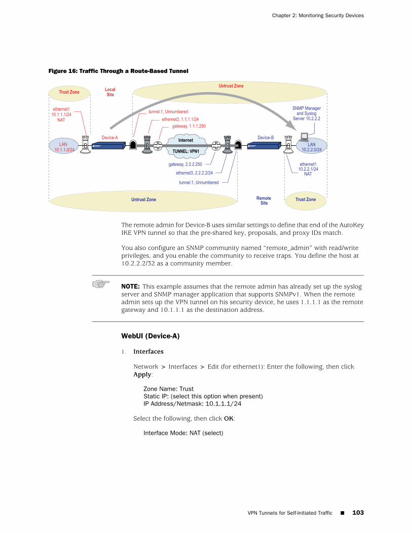
Figure 16: Traffic Through a Route-Based Tunnel
The remote admin for Device-B uses similar settings to define that end of the AutoKeyIKE VPN tunnel so that the pre-shared key, proposals, and proxy IDs match.
You also configure an SNMP community named “remote_admin” with read/writeprivileges, and you enable the community to receive traps. You define the host at10.2.2.2/32 as a community member.
NOTE: This example assumes that the remote admin has already set up the syslogserver and SNMP manager application that supports SNMPv1. When the remoteadmin sets up the VPN tunnel on his security device, he uses 1.1.1.1 as the remotegateway and 10.1.1.1 as the destination address.
WebUI (Device-A)
1. Interfaces
Network > Interfaces > Edit (for ethernet1): Enter the following, then clickApply:
Zone Name: TrustStatic IP: (select this option when present)IP Address/Netmask: 10.1.1.1/24
Select the following, then click OK:
Interface Mode: NAT (select)
VPN Tunnels for Self-Initiated Traffic ■ 103
Chapter 2: Monitoring Security Devices
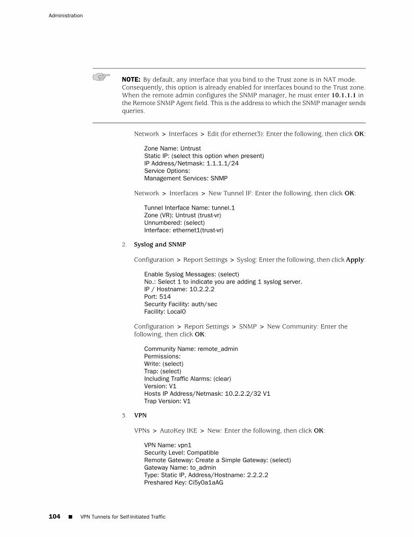
NOTE: By default, any interface that you bind to the Trust zone is in NAT mode.Consequently, this option is already enabled for interfaces bound to the Trust zone.When the remote admin configures the SNMP manager, he must enter 10.1.1.1 inthe Remote SNMP Agent field. This is the address to which the SNMP manager sendsqueries.
Network > Interfaces > Edit (for ethernet3): Enter the following, then click OK:
Zone Name: UntrustStatic IP: (select this option when present)IP Address/Netmask: 1.1.1.1/24Service Options:Management Services: SNMP
Network > Interfaces > New Tunnel IF: Enter the following, then click OK:
Tunnel Interface Name: tunnel.1Zone (VR): Untrust (trust-vr)Unnumbered: (select)Interface: ethernet1(trust-vr)
2. Syslog and SNMP
Configuration > Report Settings > Syslog: Enter the following, then click Apply:
Enable Syslog Messages: (select)No.: Select 1 to indicate you are adding 1 syslog server.IP / Hostname: 10.2.2.2Port: 514Security Facility: auth/secFacility: Local0
Configuration > Report Settings > SNMP > New Community: Enter thefollowing, then click OK:
Community Name: remote_adminPermissions:Write: (select)Trap: (select)Including Traffic Alarms: (clear)Version: V1Hosts IP Address/Netmask: 10.2.2.2/32 V1Trap Version: V1
3. VPN
VPNs > AutoKey IKE > New: Enter the following, then click OK:
VPN Name: vpn1Security Level: CompatibleRemote Gateway: Create a Simple Gateway: (select)Gateway Name: to_adminType: Static IP, Address/Hostname: 2.2.2.2Preshared Key: Ci5y0a1aAG
104 ■ VPN Tunnels for Self-Initiated Traffic
Administration
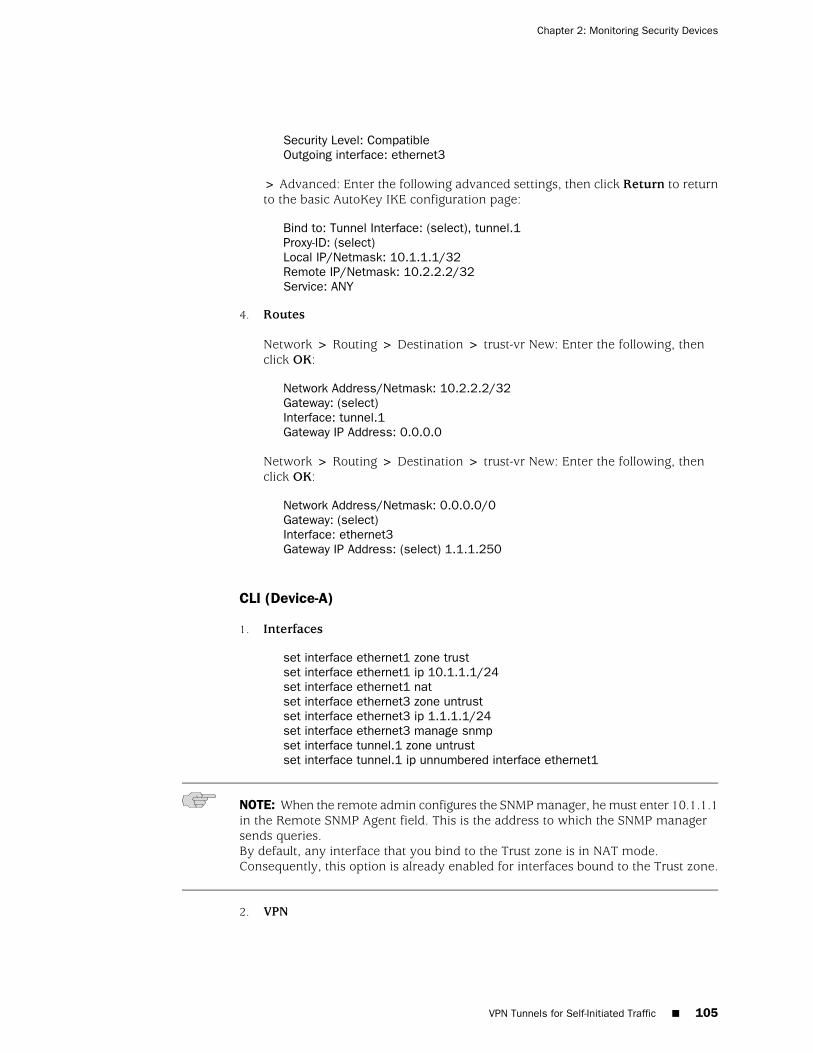
Security Level: CompatibleOutgoing interface: ethernet3
> Advanced: Enter the following advanced settings, then click Return to returnto the basic AutoKey IKE configuration page:
Bind to: Tunnel Interface: (select), tunnel.1Proxy-ID: (select)Local IP/Netmask: 10.1.1.1/32Remote IP/Netmask: 10.2.2.2/32Service: ANY
4. Routes
Network > Routing > Destination > trust-vr New: Enter the following, thenclick OK:
Network Address/Netmask: 10.2.2.2/32Gateway: (select)Interface: tunnel.1Gateway IP Address: 0.0.0.0
Network > Routing > Destination > trust-vr New: Enter the following, thenclick OK:
Network Address/Netmask: 0.0.0.0/0Gateway: (select)Interface: ethernet3Gateway IP Address: (select) 1.1.1.250
CLI (Device-A)
1. Interfaces
set interface ethernet1 zone trustset interface ethernet1 ip 10.1.1.1/24set interface ethernet1 natset interface ethernet3 zone untrustset interface ethernet3 ip 1.1.1.1/24set interface ethernet3 manage snmpset interface tunnel.1 zone untrustset interface tunnel.1 ip unnumbered interface ethernet1
NOTE: When the remote admin configures the SNMP manager, he must enter 10.1.1.1in the Remote SNMP Agent field. This is the address to which the SNMP managersends queries.By default, any interface that you bind to the Trust zone is in NAT mode.Consequently, this option is already enabled for interfaces bound to the Trust zone.
2. VPN
VPN Tunnels for Self-Initiated Traffic ■ 105
Chapter 2: Monitoring Security Devices
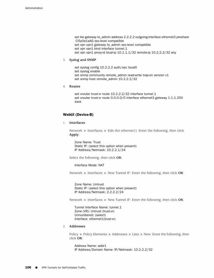
set ike gateway to_admin address 2.2.2.2 outgoing-interface ethernet3 preshare Ci5y0a1aAG sec-level compatibleset vpn vpn1 gateway to_admin sec-level compatibleset vpn vpn1 bind interface tunnel.1set vpn vpn1 proxy-id local-ip 10.1.1.1/32 remote-ip 10.2.2.2/32 any
3. Syslog and SNMP
set syslog config 10.2.2.2 auth/sec local0set syslog enableset snmp community remote_admin read-write trap-on version v1set snmp host remote_admin 10.2.2.2/32
4. Routes
set vrouter trust-vr route 10.2.2.2/32 interface tunnel.1set vrouter trust-vr route 0.0.0.0/0 interface ethernet3 gateway 1.1.1.250save
WebUI (Device-B)
1. Interfaces
Network > Interfaces > Edit (for ethernet1): Enter the following, then clickApply:
Zone Name: TrustStatic IP: (select this option when present)IP Address/Netmask: 10.2.2.1/24
Select the following, then click OK:
Interface Mode: NAT
Network > Interfaces > New Tunnel IF: Enter the following, then click OK:
Zone Name: UntrustStatic IP: (select this option when present)IP Address/Netmask: 2.2.2.2/24
Network > Interfaces > New Tunnel IF: Enter the following, then click OK:
Tunnel Interface Name: tunnel.1Zone (VR): Untrust (trust-vr)Unnumbered: (select)Interface: ethernet1(trust-vr)
2. Addresses
Policy > Policy Elements > Addresses > Lists > New: Enter the following, thenclick OK:
Address Name: addr1IP Address/Domain Name: IP/Netmask: 10.2.2.2/32
106 ■ VPN Tunnels for Self-Initiated Traffic
Administration
Zone: Trust
Policy > Policy Elements > Addresses > Lists > New: Enter the following, thenclick OK:
Address Name: ns-aIP Address/Domain Name: IP/Netmask: 10.1.1.1/32Zone: Untrust
3. Service Group
Policy > Policy Elements > Services > Groups > New: Enter the followinggroup name, move the following services, then click OK:
Group Name: s-grp1
Select Syslog and use the << button to move the service from the AvailableMembers column to the Group Members column.
Select SNMP and use the << button to move the service from the AvailableMembers column to the Group Members column.
4. VPN
VPNs > AutoKey IKE > New: Enter the following, then click OK:
VPN Name: vpn1Security Level: CompatibleRemote Gateway: Create a Simple Gateway: (select)Gateway Name: to_adminType: Static IP, Address/Hostname: 1.1.1.1Preshared Key: Ci5y0a1aAGSecurity Level: CompatibleOutgoing Interface: ethernet3
> Advanced: Enter the following advanced settings, then click Return to returnto the basic AutoKey IKE configuration page:
Bind to: Tunnel Interface: (select), tunnel.1Proxy-ID: (select)Local IP/Netmask: 10.2.2.2/32Remote IP/Netmask: 10.1.1.1/32Service: Any
5. Routes
Network > Routing > Destination > trust-vr New: Enter the following, thenclick OK:
Network Address/Netmask:10.1.1.1/32Gateway: (select)Interface: tunnel.1Gateway IP Address: 0.0.0.0
VPN Tunnels for Self-Initiated Traffic ■ 107
Chapter 2: Monitoring Security Devices
Network > Routing > Destination > trust-vr New: Enter the following, thenclick OK:
Network Address/Netmask: 0.0.0.0/0Gateway: (select)Interface: ethernet3Gateway IP Address: (select) 2.2.2.250
6. Policies
Policies > (From: Trust, To: Untrust) New: Enter the following, then click OK:
Source Address:Address Book Entry: (select), addr1Destination Address:Address Book Entry: (select), ns-aService: s-grp1Action: PermitPosition at Top: (select)
Policies > (From: Untrust, To: Trust) New: Enter the following, then click OK:
Source Address:Address Book Entry: (select), ns-aDestination Address:Address Book Entry: (select), addr1Service: s-grp1Action: PermitPosition at Top: (select)
CLI (Device-B)
1. Interfaces
set interface ethernet1 zone trustset interface ethernet1 ip 10.2.2.1/24set interface ethernet1 natset interface ethernet3 zone untrustset interface ethernet3 ip 2.2.2.2/24set interface tunnel.1 zone untrustset interface tunnel.1 ip unnumbered interface ethernet1
2. Addresses
set address trust addr1 10.2.2.2/32set address untrust ns-a 10.1.1.1/32
3. Service Group
set group service s-grp1 set group service s-grp1 add syslogset group service s-grp1 add snmp
4. VPN
108 ■ VPN Tunnels for Self-Initiated Traffic
Administration
set ike gateway to_admin address 1.1.1.1 outgoing-interface ethernet3 preshare Ci5y0a1aAG sec-level compatibleset vpn vpn1 gateway to_admin sec-level compatibleset vpn vpn1 bind interface tunnel.1set vpn vpn1 proxy-id local-ip 10.2.2.2/32 remote-ip 10.1.1.1/32 any
5. Routes
set vrouter trust-vr route 10.1.1.1/32 interface tunnel.1set vrouter trust-vr route 0.0.0.0/0 interface ethernet3 gateway 2.2.2.250
6. Policies
set policy top from trust to untrust addr1 ns-a s-grp1 permitset policy top from untrust to trust ns-a addr1 s-grp1 permitsave
Example: Self-Generated Traffic Through a Policy-Based Tunnel
In this example (illustrated in Figure 17 on page 110), you configure a local securitydevice (Device-A) to send SNMPv2c MIB traps and syslog reports through apolicy-based AutoKey IKE VPN tunnel (vpn1) to an SNMP community member behinda remote security device (Device-B). The tunnel uses a preshared key (Ci5y0a1aAG)for data origin authentication and the security level predefined as “ompatible” forboth Phase 1 and Phase 2 proposals.
NOTE: This example assumes that the remote admin has already set up the syslogserver and an SNMP manager application that supports SNMPv2c. When the remoteadmin sets up the VPN tunnel on his security device, he uses 1.1.1.1 as the remotegateway and 10.1.1.1 as the destination address.
Both you and the remote admin bind ethernet1 to the Trust zone, and ethernet3 tothe Untrust zone on Device-A and Device-B. The default gateway IP address forDevice-A is 1.1.1.250. The default gateway IP address for Device-B is 2.2.2.250. Allzones are in the trust-vr routing domain.
VPN Tunnels for Self-Initiated Traffic ■ 109
Chapter 2: Monitoring Security Devices
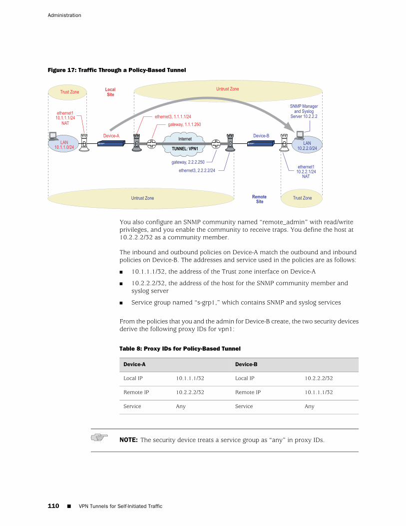
Figure 17: Traffic Through a Policy-Based Tunnel
You also configure an SNMP community named “remote_admin” with read/writeprivileges, and you enable the community to receive traps. You define the host at10.2.2.2/32 as a community member.
The inbound and outbound policies on Device-A match the outbound and inboundpolicies on Device-B. The addresses and service used in the policies are as follows:
■ 10.1.1.1/32, the address of the Trust zone interface on Device-A
■ 10.2.2.2/32, the address of the host for the SNMP community member andsyslog server
■ Service group named “s-grp1,” which contains SNMP and syslog services
From the policies that you and the admin for Device-B create, the two security devicesderive the following proxy IDs for vpn1:
Table 8: Proxy IDs for Policy-Based Tunnel
Device-BDevice-A
10.2.2.2/32Local IP10.1.1.1/32Local IP
10.1.1.1/32Remote IP10.2.2.2/32Remote IP
AnyServiceAnyService
NOTE: The security device treats a service group as “any” in proxy IDs.
110 ■ VPN Tunnels for Self-Initiated Traffic
Administration
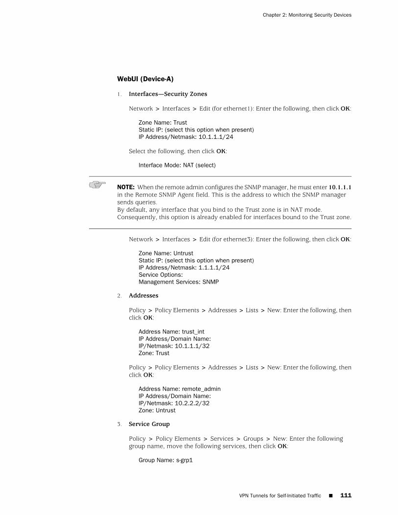
WebUI (Device-A)
1. Interfaces—Security Zones
Network > Interfaces > Edit (for ethernet1): Enter the following, then click OK:
Zone Name: TrustStatic IP: (select this option when present)IP Address/Netmask: 10.1.1.1/24
Select the following, then click OK:
Interface Mode: NAT (select)
NOTE: When the remote admin configures the SNMP manager, he must enter 10.1.1.1in the Remote SNMP Agent field. This is the address to which the SNMP managersends queries.By default, any interface that you bind to the Trust zone is in NAT mode.Consequently, this option is already enabled for interfaces bound to the Trust zone.
Network > Interfaces > Edit (for ethernet3): Enter the following, then click OK:
Zone Name: UntrustStatic IP: (select this option when present)IP Address/Netmask: 1.1.1.1/24Service Options:Management Services: SNMP
2. Addresses
Policy > Policy Elements > Addresses > Lists > New: Enter the following, thenclick OK:
Address Name: trust_intIP Address/Domain Name:IP/Netmask: 10.1.1.1/32Zone: Trust
Policy > Policy Elements > Addresses > Lists > New: Enter the following, thenclick OK:
Address Name: remote_adminIP Address/Domain Name:IP/Netmask: 10.2.2.2/32Zone: Untrust
3. Service Group
Policy > Policy Elements > Services > Groups > New: Enter the followinggroup name, move the following services, then click OK:
Group Name: s-grp1
VPN Tunnels for Self-Initiated Traffic ■ 111
Chapter 2: Monitoring Security Devices
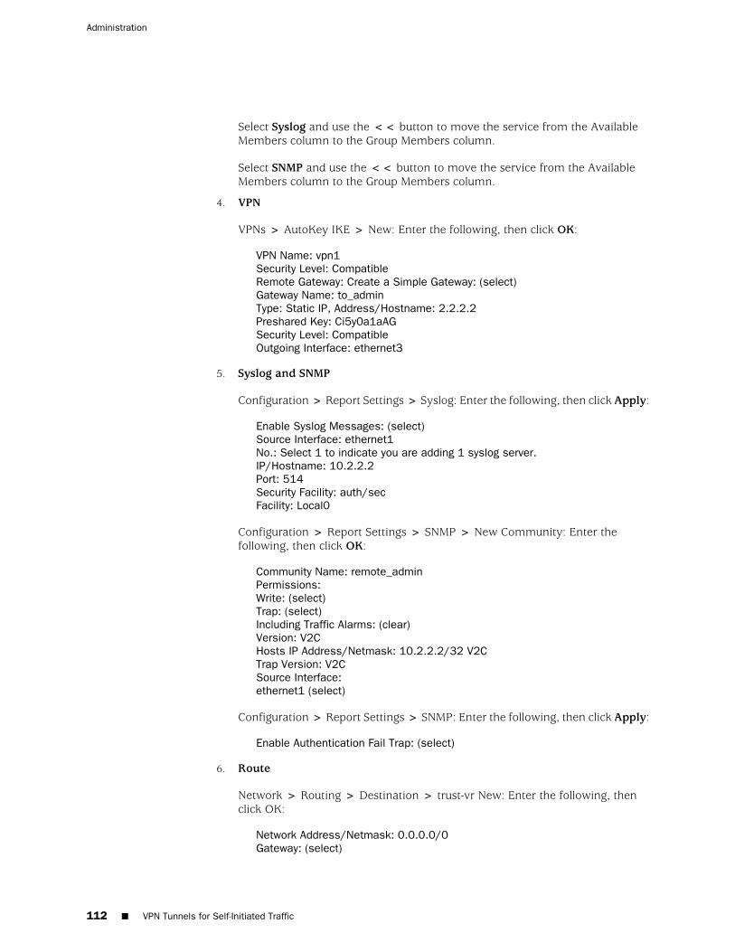
Select Syslog and use the << button to move the service from the AvailableMembers column to the Group Members column.
Select SNMP and use the << button to move the service from the AvailableMembers column to the Group Members column.
4. VPN
VPNs > AutoKey IKE > New: Enter the following, then click OK:
VPN Name: vpn1Security Level: CompatibleRemote Gateway: Create a Simple Gateway: (select)Gateway Name: to_adminType: Static IP, Address/Hostname: 2.2.2.2Preshared Key: Ci5y0a1aAGSecurity Level: CompatibleOutgoing Interface: ethernet3
5. Syslog and SNMP
Configuration > Report Settings > Syslog: Enter the following, then click Apply:
Enable Syslog Messages: (select)Source Interface: ethernet1No.: Select 1 to indicate you are adding 1 syslog server.IP/Hostname: 10.2.2.2Port: 514Security Facility: auth/secFacility: Local0
Configuration > Report Settings > SNMP > New Community: Enter thefollowing, then click OK:
Community Name: remote_adminPermissions:Write: (select)Trap: (select)Including Traffic Alarms: (clear)Version: V2CHosts IP Address/Netmask: 10.2.2.2/32 V2CTrap Version: V2CSource Interface:ethernet1 (select)
Configuration > Report Settings > SNMP: Enter the following, then click Apply:
Enable Authentication Fail Trap: (select)
6. Route
Network > Routing > Destination > trust-vr New: Enter the following, thenclick OK:
Network Address/Netmask: 0.0.0.0/0Gateway: (select)
112 ■ VPN Tunnels for Self-Initiated Traffic
Administration
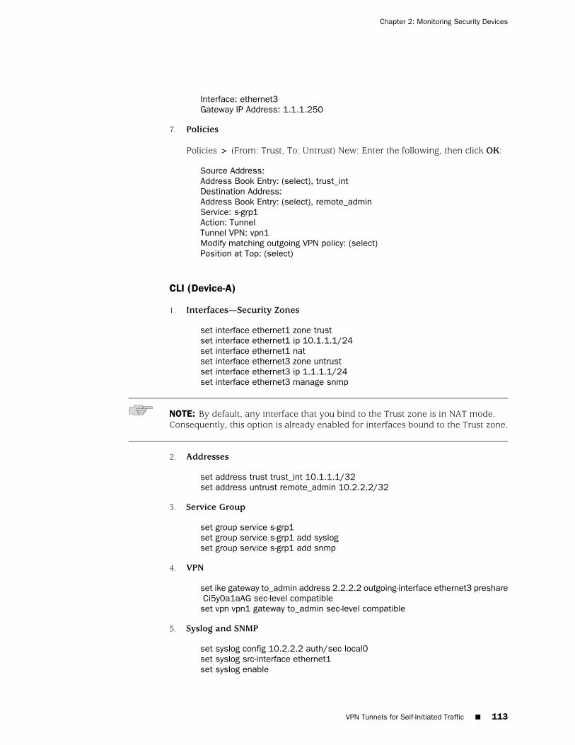
Interface: ethernet3Gateway IP Address: 1.1.1.250
7. Policies
Policies > (From: Trust, To: Untrust) New: Enter the following, then click OK:
Source Address:Address Book Entry: (select), trust_intDestination Address:Address Book Entry: (select), remote_adminService: s-grp1Action: TunnelTunnel VPN: vpn1Modify matching outgoing VPN policy: (select)Position at Top: (select)
CLI (Device-A)
1. Interfaces—Security Zones
set interface ethernet1 zone trustset interface ethernet1 ip 10.1.1.1/24set interface ethernet1 natset interface ethernet3 zone untrustset interface ethernet3 ip 1.1.1.1/24set interface ethernet3 manage snmp
NOTE: By default, any interface that you bind to the Trust zone is in NAT mode.Consequently, this option is already enabled for interfaces bound to the Trust zone.
2. Addresses
set address trust trust_int 10.1.1.1/32set address untrust remote_admin 10.2.2.2/32
3. Service Group
set group service s-grp1 set group service s-grp1 add syslogset group service s-grp1 add snmp
4. VPN
set ike gateway to_admin address 2.2.2.2 outgoing-interface ethernet3 preshare Ci5y0a1aAG sec-level compatibleset vpn vpn1 gateway to_admin sec-level compatible
5. Syslog and SNMP
set syslog config 10.2.2.2 auth/sec local0set syslog src-interface ethernet1set syslog enable
VPN Tunnels for Self-Initiated Traffic ■ 113
Chapter 2: Monitoring Security Devices
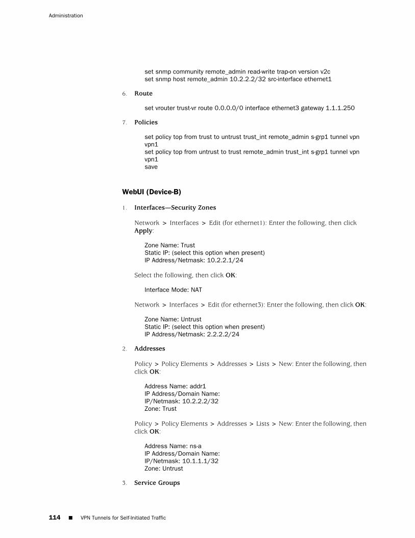
set snmp community remote_admin read-write trap-on version v2cset snmp host remote_admin 10.2.2.2/32 src-interface ethernet1
6. Route
set vrouter trust-vr route 0.0.0.0/0 interface ethernet3 gateway 1.1.1.250
7. Policies
set policy top from trust to untrust trust_int remote_admin s-grp1 tunnel vpn vpn1set policy top from untrust to trust remote_admin trust_int s-grp1 tunnel vpn vpn1save
WebUI (Device-B)
1. Interfaces—Security Zones
Network > Interfaces > Edit (for ethernet1): Enter the following, then clickApply:
Zone Name: TrustStatic IP: (select this option when present)IP Address/Netmask: 10.2.2.1/24
Select the following, then click OK:
Interface Mode: NAT
Network > Interfaces > Edit (for ethernet3): Enter the following, then click OK:
Zone Name: UntrustStatic IP: (select this option when present)IP Address/Netmask: 2.2.2.2/24
2. Addresses
Policy > Policy Elements > Addresses > Lists > New: Enter the following, thenclick OK:
Address Name: addr1IP Address/Domain Name:IP/Netmask: 10.2.2.2/32Zone: Trust
Policy > Policy Elements > Addresses > Lists > New: Enter the following, thenclick OK:
Address Name: ns-aIP Address/Domain Name:IP/Netmask: 10.1.1.1/32Zone: Untrust
3. Service Groups
114 ■ VPN Tunnels for Self-Initiated Traffic
Administration
Policy > Policy Elements > Services > Group: Enter the following group name,move the following services, then click OK:
Group Name: s-grp1
Select Syslog and use the << button to move the service from the AvailableMembers column to the Group Members column.
Select SNMP and use the << button to move the service from the AvailableMembers column to the Group Members column.
4. VPN
VPNs > AutoKey IKE > New: Enter the following, then click OK:
VPN Name: vpn1Security Level: CompatibleRemote Gateway: Create a Simple Gateway: (select)Gateway Name: to_adminType: Static IP, IP Address: 1.1.1.1Preshared Key: Ci5y0a1aAGSecurity Level: CompatibleOutgoing interface: ethernet3
5. Route
Network > Routing > Routing Table > trust-vr New: Enter the following, thenclick OK:
Network Address/Netmask: 0.0.0.0/0Gateway: (select)Interface: ethernet3Gateway IP Address: (select) 2.2.2.250
6. Policies
Policies > (From: Trust, To: Untrust) New: Enter the following, then click OK:
Source Address:Address Book Entry: (select), addr1Destination Address:Address Book Entry: (select), ns-aService: s-grp1Action: TunnelTunnel VPN: vpn1Modify matching outgoing VPN policy: (select)Position at Top: (select)
CLI (Device-B)
1. Interfaces—Security Zones
set interface ethernet1 zone trustset interface ethernet1 ip 10.2.2.1/24set interface ethernet1 nat
VPN Tunnels for Self-Initiated Traffic ■ 115
Chapter 2: Monitoring Security Devices
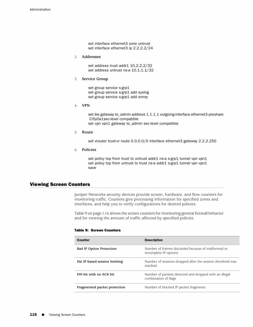
set interface ethernet3 zone untrustset interface ethernet3 ip 2.2.2.2/24
2. Addresses
set address trust addr1 10.2.2.2/32set address untrust ns-a 10.1.1.1/32
3. Service Group
set group service s-grp1 set group service s-grp1 add syslogset group service s-grp1 add snmp
4. VPN
set ike gateway to_admin address 1.1.1.1 outgoing-interface ethernet3 preshare Ci5y0a1sec-level compatibleset vpn vpn1 gateway to_admin sec-level compatible
5. Route
set vrouter trust-vr route 0.0.0.0/0 interface ethernet3 gateway 2.2.2.250
6. Policies
set policy top from trust to untrust addr1 ns-a s-grp1 tunnel vpn vpn1set policy top from untrust to trust ns-a addr1 s-grp1 tunnel vpn vpn1save
Viewing Screen Counters
Juniper Networks security devices provide screen, hardware, and flow counters formonitoring traffic. Counters give processing information for specified zones andinterfaces, and help you to verify configurations for desired policies.
Table 9 on page 116 shows the screen counters for monitoring general firewall behaviorand for viewing the amount of traffic affected by specified policies.
Table 9: Screen Counters
DescriptionCounter
Number of frames discarded because of malformed orincomplete IP options
Bad IP Option Protection
Number of sessions dropped after the session threshold wasreached
Dst IP-based session limiting
Number of packets detected and dropped with an illegalcombination of flags
FIN bit with no ACK bit
Number of blocked IP packet fragmentsFragmented packet protection
116 ■ Viewing Screen Counters
Administration
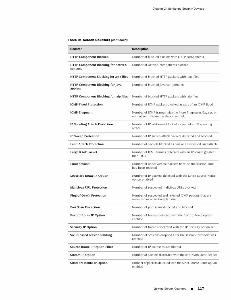
Table 9: Screen Counters (continued)
DescriptionCounter
Number of blocked packets with HTTP componentsHTTP Component Blocked
Number of ActiveX components blockedHTTP Component Blocking for ActiveXcontrols
Number of blocked HTTP packets with .exe filesHTTP Component Blocking for .exe files
Number of blocked Java componentsHTTP Component Blocking for Javaapplets
Number of blocked HTTP packets with .zip filesHTTP Component Blocking for .zip files
Number of ICMP packets blocked as part of an ICMP floodICMP Flood Protection
Number of ICMP frames with the More Fragments flag set, orwith offset indicated in the Offset field
ICMP Fragment
Number of IP addresses blocked as part of an IP spoofingattack
IP Spoofing Attack Protection
Number of IP sweep attack packets detected and blockedIP Sweep Protection
Number of packets blocked as part of a suspected land attackLand Attack Protection
Number of ICMP frames detected with an IP length greaterthan 1024
Large ICMP Packet
Number of undeliverable packets because the session limithad been reached
Limit Session
Number of IP packets detected with the Loose Source Routeoption enabled
Loose Src Route IP Option
Number of suspected malicious URLs blockedMalicious URL Protection
Number of suspected and rejected ICMP packets that areoversized or of an irregular size
Ping-of-Death Protection
Number of port scans detected and blockedPort Scan Protection
Number of frames detected with the Record Route optionenabled
Record Route IP Option
Number of frames discarded with the IP Security option setSecurity IP Option
Number of sessions dropped after the session threshold wasreached
Src IP-based session limiting
Number of IP source routes filteredSource Route IP Option Filter
Number of packets discarded with the IP Stream identifier setStream IP Option
Number of packets detected with the Strict Source Route optionenabled
Strict Src Route IP Option
Viewing Screen Counters ■ 117
Chapter 2: Monitoring Security Devices
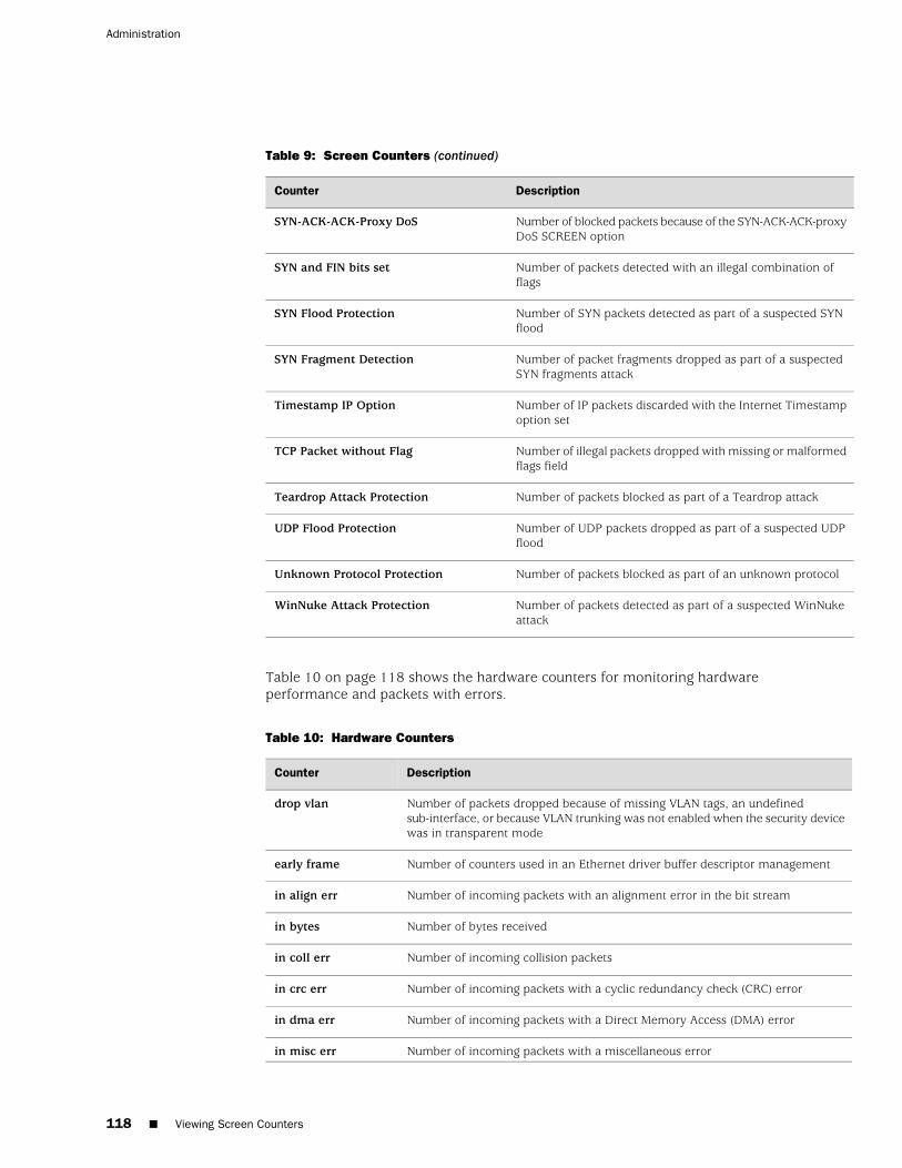
Table 9: Screen Counters (continued)
DescriptionCounter
Number of blocked packets because of the SYN-ACK-ACK-proxyDoS SCREEN option
SYN-ACK-ACK-Proxy DoS
Number of packets detected with an illegal combination offlags
SYN and FIN bits set
Number of SYN packets detected as part of a suspected SYNflood
SYN Flood Protection
Number of packet fragments dropped as part of a suspectedSYN fragments attack
SYN Fragment Detection
Number of IP packets discarded with the Internet Timestampoption set
Timestamp IP Option
Number of illegal packets dropped with missing or malformedflags field
TCP Packet without Flag
Number of packets blocked as part of a Teardrop attackTeardrop Attack Protection
Number of UDP packets dropped as part of a suspected UDPflood
UDP Flood Protection
Number of packets blocked as part of an unknown protocolUnknown Protocol Protection
Number of packets detected as part of a suspected WinNukeattack
WinNuke Attack Protection
Table 10 on page 118 shows the hardware counters for monitoring hardwareperformance and packets with errors.
Table 10: Hardware Counters
DescriptionCounter
Number of packets dropped because of missing VLAN tags, an undefinedsub-interface, or because VLAN trunking was not enabled when the security devicewas in transparent mode
drop vlan
Number of counters used in an Ethernet driver buffer descriptor managementearly frame
Number of incoming packets with an alignment error in the bit streamin align err
Number of bytes receivedin bytes
Number of incoming collision packetsin coll err
Number of incoming packets with a cyclic redundancy check (CRC) errorin crc err
Number of incoming packets with a Direct Memory Access (DMA) errorin dma err
Number of incoming packets with a miscellaneous errorin misc err
118 ■ Viewing Screen Counters
Administration
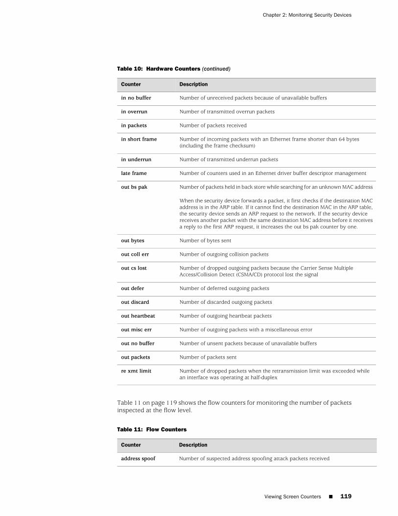
Table 10: Hardware Counters (continued)
DescriptionCounter
Number of unreceived packets because of unavailable buffersin no buffer
Number of transmitted overrun packetsin overrun
Number of packets receivedin packets
Number of incoming packets with an Ethernet frame shorter than 64 bytes(including the frame checksum)
in short frame
Number of transmitted underrun packetsin underrun
Number of counters used in an Ethernet driver buffer descriptor managementlate frame
Number of packets held in back store while searching for an unknown MAC address
When the security device forwards a packet, it first checks if the destination MACaddress is in the ARP table. If it cannot find the destination MAC in the ARP table,the security device sends an ARP request to the network. If the security devicereceives another packet with the same destination MAC address before it receivesa reply to the first ARP request, it increases the out bs pak counter by one.
out bs pak
Number of bytes sentout bytes
Number of outgoing collision packetsout coll err
Number of dropped outgoing packets because the Carrier Sense MultipleAccess/Collision Detect (CSMA/CD) protocol lost the signal
out cs lost
Number of deferred outgoing packetsout defer
Number of discarded outgoing packetsout discard
Number of outgoing heartbeat packetsout heartbeat
Number of outgoing packets with a miscellaneous errorout misc err
Number of unsent packets because of unavailable buffersout no buffer
Number of packets sentout packets
Number of dropped packets when the retransmission limit was exceeded whilean interface was operating at half-duplex
re xmt limit
Table 11 on page 119 shows the flow counters for monitoring the number of packetsinspected at the flow level.
Table 11: Flow Counters
DescriptionCounter
Number of suspected address spoofing attack packets receivedaddress spoof
Viewing Screen Counters ■ 119
Chapter 2: Monitoring Security Devices
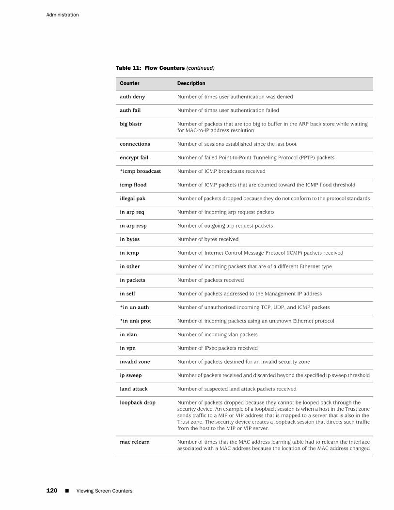
Table 11: Flow Counters (continued)
DescriptionCounter
Number of times user authentication was deniedauth deny
Number of times user authentication failedauth fail
Number of packets that are too big to buffer in the ARP back store while waitingfor MAC-to-IP address resolution
big bkstr
Number of sessions established since the last bootconnections
Number of failed Point-to-Point Tunneling Protocol (PPTP) packetsencrypt fail
Number of ICMP broadcasts received*icmp broadcast
Number of ICMP packets that are counted toward the ICMP flood thresholdicmp flood
Number of packets dropped because they do not conform to the protocol standardsillegal pak
Number of incoming arp request packetsin arp req
Number of outgoing arp request packetsin arp resp
Number of bytes receivedin bytes
Number of Internet Control Message Protocol (ICMP) packets receivedin icmp
Number of incoming packets that are of a different Ethernet typein other
Number of packets receivedin packets
Number of packets addressed to the Management IP addressin self
Number of unauthorized incoming TCP, UDP, and ICMP packets*in un auth
Number of incoming packets using an unknown Ethernet protocol*in unk prot
Number of incoming vlan packetsin vlan
Number of IPsec packets receivedin vpn
Number of packets destined for an invalid security zoneinvalid zone
Number of packets received and discarded beyond the specified ip sweep thresholdip sweep
Number of suspected land attack packets receivedland attack
Number of packets dropped because they cannot be looped back through thesecurity device. An example of a loopback session is when a host in the Trust zonesends traffic to a MIP or VIP address that is mapped to a server that is also in theTrust zone. The security device creates a loopback session that directs such trafficfrom the host to the MIP or VIP server.
loopback drop
Number of times that the MAC address learning table had to relearn the interfaceassociated with a MAC address because the location of the MAC address changed
mac relearn
120 ■ Viewing Screen Counters
Administration
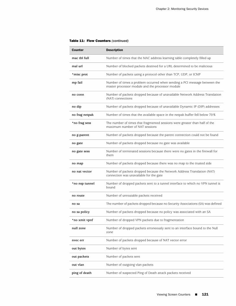
Table 11: Flow Counters (continued)
DescriptionCounter
Number of times that the MAC address learning table completely filled upmac tbl full
Number of blocked packets destined for a URL determined to be maliciousmal url
Number of packets using a protocol other than TCP, UDP, or ICMP*misc prot
Number of times a problem occurred when sending a PCI message between themaster processor module and the processor module
mp fail
Number of packets dropped because of unavailable Network Address Translation(NAT) connections
no conn
Number of packets dropped because of unavailable Dynamic IP (DIP) addressesno dip
Number of times that the available space in the netpak buffer fell below 70%no frag netpak
The number of times that fragmented sessions were greater than half of themaximum number of NAT sessions
*no frag sess
Number of packets dropped because the parent connection could not be foundno g-parent
Number of packets dropped because no gate was availableno gate
Number of terminated sessions because there were no gates in the firewall forthem
no gate sess
Number of packets dropped because there was no map to the trusted sideno map
Number of packets dropped because the Network Address Translation (NAT)connection was unavailable for the gate
no nat vector
Number of dropped packets sent to a tunnel interface to which no VPN tunnel isbound
*no nsp tunnel
Number of unroutable packets receivedno route
The number of packets dropped because no Security Associations (SA) was definedno sa
Number of packets dropped because no policy was associated with an SAno sa policy
Number of dropped VPN packets due to fragmentation*no xmit vpnf
Number of dropped packets erroneously sent to an interface bound to the Nullzone
null zone
Number of packets dropped because of NAT vector errornvec err
Number of bytes sentout bytes
Number of packets sentout packets
Number of outgoing vlan packetsout vlan
Number of suspected Ping of Death attack packets receivedping of death
Viewing Screen Counters ■ 121
Chapter 2: Monitoring Security Devices
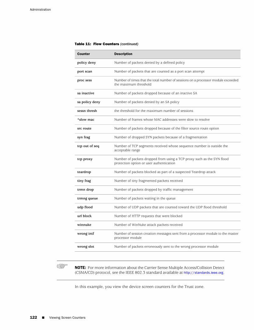
Table 11: Flow Counters (continued)
DescriptionCounter
Number of packets denied by a defined policypolicy deny
Number of packets that are counted as a port scan attemptport scan
Number of times that the total number of sessions on a processor module exceededthe maximum threshold
proc sess
Number of packets dropped because of an inactive SAsa inactive
Number of packets denied by an SA policysa policy deny
the threshold for the maximum number of sessionssessn thresh
Number of frames whose MAC addresses were slow to resolve*slow mac
Number of packets dropped because of the filter source route optionsrc route
Number of dropped SYN packets because of a fragmentationsyn frag
Number of TCP segments received whose sequence number is outside theacceptable range
tcp out of seq
Number of packets dropped from using a TCP proxy such as the SYN floodprotection option or user authentication
tcp proxy
Number of packets blocked as part of a suspected Teardrop attackteardrop
Number of tiny fragmented packets receivedtiny frag
Number of packets dropped by traffic managementtrmn drop
Number of packets waiting in the queuetrmng queue
Number of UDP packets that are counted toward the UDP flood thresholdudp flood
Number of HTTP requests that were blockedurl block
Number of WinNuke attack packets receivedwinnuke
Number of session creation messages sent from a processor module to the masterprocessor module
wrong intf
Number of packets erroneously sent to the wrong processor modulewrong slot
NOTE: For more information about the Carrier Sense Multiple Access/Collision Detect(CSMA/CD) protocol, see the IEEE 802.3 standard available at http://standards.ieee.org.
In this example, you view the device screen counters for the Trust zone.
122 ■ Viewing Screen Counters
Administration

WebUI
Reports > Counters > Zone Screen: Select Trust from the Zone drop-down list.
CLI
get counter screen zone trust
Viewing Screen Counters ■ 123
Chapter 2: Monitoring Security Devices

124 ■ Viewing Screen Counters
Administration

Part 2
Index
■ Index on page 127
Index ■ 125

126 ■ Index
Administration
Index
Aadministration
CLI........................................................................13restricting.............................................................49WebUI....................................................................6
administrative traffic....................................................35alarms
email alert.............................................................79NSM, reporting to.................................................30thresholds.............................................................79traffic....................................................................79
asset recovery log........................................................78auth
priv.......................................................................94AutoKey IKE VPN...................................................52, 96
Bback store..................................................................119bit stream..................................................................118browser requirements....................................................6
Ccables, serial................................................................24CLI...............................................................................13command line interface See CLICommunity..................................................................91CompactFlash..............................................................65configuration................................................................94console........................................................................65
Ddevices, resetting to factory defaults............................48DIP.............................................................................121dynamic IP See DIP
Eemail alert notification...........................................81, 90event log......................................................................66
Ffactory defaults, resetting devices to............................48filter source route.......................................................122
HHelp files........................................................................7HTTP session ID.............................................................8HyperText Transfer Protocol See HTTP
IIdent-Reset...................................................................34in-short error..............................................................119inactive SA.................................................................122interfaces
manageable..........................................................37management options............................................33
internal flash storage....................................................65IP addresses
Manage IP.............................................................37NSM servers..........................................................30
LLocal Engine................................................................91
Boots....................................................................94logging.........................................................................65
asset recovery log.................................................78CompactFlash (PCMCIA).......................................65console.................................................................65email....................................................................65event log...............................................................65internal.................................................................65NSM......................................................................30self log..................................................................75SNMP..............................................................65, 91syslog..............................................................65, 86USB.......................................................................65WebTrends.....................................................65, 86
Mmanage IP....................................................................37
Index ■ 127
management client IP addresses..................................49Management information base II See MIB IImanagement methods
CLI........................................................................13console.................................................................24SSL..........................................................................9Telnet...................................................................14WebUI....................................................................6
management optionsinterfaces..............................................................33manageable..........................................................37MGT interface.......................................................34NSM......................................................................33ping......................................................................33SNMP....................................................................33SSH.......................................................................33SSL........................................................................33Telnet...................................................................33transparent mode.................................................34VLAN1..................................................................34WebUI..................................................................33
manual keys, VPNs................................................52, 96MD5
SHA......................................................................94messages
alert......................................................................66critical...................................................................66debug....................................................................66emergency............................................................66error.....................................................................66info.......................................................................66notification...........................................................66warning................................................................66WebTrends...........................................................86
MGT interface, management options...........................34MIB II...........................................................................91modem ports.........................................................25, 27
NNAT vector error........................................................121Network Address Translation (NAT)...........................121Network and Security Manager See NSMNSM
definition..............................................................27enabling NSM Agent.............................................29events, reporting...................................................30initial connectivity setup.......................................28logging..................................................................30management options............................................33management system......................................28, 30NSM Agent......................................................27, 30reporting events....................................................30UI..........................................................................27
NSM Agent.............................................................27, 28enabling................................................................29events, reporting...................................................30
Oobject identifier............................................................94OID..............................................................................91
Ppackets......................................................................122
address spoofing attack......................................119collision......................................................118, 119denied................................................................122dropped......................................................121, 122fragmented.........................................................122incoming............................................................118Internet Control Message Protocol
(ICMP).....................................................117, 120IPsec...................................................................120land attack..........................................................120Network Address Translation (NAT)....................121Point to Point Tunneling Protocol (PPTP)............120received......................................118, 119, 120, 121transmitted underrun..........................................119unreceivable.......................................................119unroutable..........................................................121
parent connection......................................................121passwords
forgetting..............................................................46root admin............................................................47
PCMCIA........................................................................65ping management options...........................................33PKI keys.......................................................................10Point-to-Point Tunneling Protocol (PPTP)...................120ports, modem........................................................24, 27protocol distribution, NSM, reporting to.......................30
RRADIUS........................................................................47root admin, logging in..................................................50
SSA policy....................................................................122SCP
enabling................................................................23example client command.....................................23
Secure Copy See SCPSecure Shell See SSHSecure Sockets Layer See SSLSecurity
ModelLevel..............................................................94
128 ■ Index
Administration
Security Associations (SA)..........................................121self log.........................................................................75serial cables ................................................................24session ID......................................................................8SMTP server IP.............................................................81SNMP.....................................................................34, 91
cold start trap.......................................................91configuration........................................................93encryption......................................................93, 96management options............................................33
SNMP communityprivate..................................................................93public....................................................................93
SNMP traps100, hardware problems.......................................91200, firewall problems..........................................91300, software problems........................................91400, traffic problems............................................91500, VPN problems...............................................91allow or deny........................................................93system alarm........................................................91traffic alarm..........................................................91types.....................................................................91
SNMPv3encryption............................................................94framework............................................................91
source route...............................................................122SSH..............................................................................15
authentication method priority.............................18automated logins..................................................22connection procedure...........................................16forcing PKA authentication only............................18loading public keys, TFTP...............................18, 23management options............................................33password authentication.......................................18PKA......................................................................18
SSL.................................................................................9SSL Handshake Protocol See SSLHPSSL management options.............................................33SSLHP............................................................................9statistics, reporting to NSM..........................................30syslog...........................................................................65
encryption............................................................96facility...................................................................86host......................................................................86hostname..............................................86, 103, 110messages..............................................................86port.......................................................................86security facility......................................................86
Ttag
target....................................................................94TCP proxy..................................................................122Telnet...........................................................................14
Telnet management options........................................33Telnet, logging in with..................................................14traffic alarms................................................................79transparent mode, management options.....................34
UUSB..............................................................................65User-based Access Model
USM......................................................................91users, multiple administrative......................................39USM
user......................................................................94
VVACM
views....................................................................94View-based Access Control Model
VACM...................................................................91virtual private networks See VPNsvirtual systems
admins..................................................................41read-only admins..................................................41
VLAN1, management options......................................34VPNs
AutoKey IKE...................................................52, 96for administrative traffic.......................................96manual key...........................................................96manual keys.........................................................52
WWeb user interface See WebUIWebTrends............................................................65, 86
encryption......................................................86, 96messages..............................................................86
WebUI............................................................................6Help files.................................................................7management options............................................33
Index ■ 129
Index

130 ■ Index
Administration


![[XLS] · Web view400 630 630 400 630 990 990 630 630 630 630 990 990 990 990 990 990 400 400 990 630 990 630 630 400 990 990 990 990 990 630 630 990 990 630 630 990 990 990 990 990](https://img.pdfslide.us/doc/110x75/5af695027f8b9a5b1e8f4d8f/xls-view400-630-630-400-630-990-990-630-630-630-630-990-990-990-990-990-990-400.jpg)