Embed Size (px)
Citation preview
Series CKP1[Built-in strong magnet type]
Clevis width12.5 mm is now available.
16.5 mm/19.5 mm
Easy speed adjustmentEasy speed adjustment
Easy fine speed adjustment with screw adjustment construction
[Series CKP1/Built-in strong magnet type]
D-P79WSE, D-P74L/Z
Magnetic field resistant auto switchesMountable from 3 directions[Series CKG1/Built-in standard magnet type]
D-P3DWA, D-P4DWPossible to select depending on the application
Total tube length
Total tube length
Speed controller valve
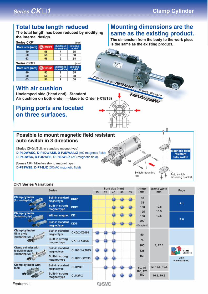
Total tube length reduced
Hexagonwrench
Total tube length
reduced by
(CKP1�40)
7mm
Retaining construction with crimping
Clevis is mounted.
Made to OrderWith air cushion on both ends (-X1515) is added.
CAT.EUS20-225Bb-UK
NewNewRoHS
Series CK�1
Clamp Cylinderø40, ø50, ø63
Series CK�1 Clamp Cylinder
[Series CKG1/Built-in standard magnet type]
D-P3DWASC, D-P3DWASE, D-P3DWA/L/Z (AC magnetic field)
D-P4DWSC, D-P4DWSE, D-P4DWL/Z (AC magnetic field)
[Series CKP1/Built-in strong magnet type]
D-P79WSE, D-P74L/Z (DC/AC magnetic field)
Switch mountingrod
Auto switch mounting bracket
Magnetic fieldresistant
auto switch
Total tube length reduced
Bore size [mm] CKP1 Shorteneddimensions
58
56
56
7
2
2
Existingmodel
[mm]
65
58
58
40
50
63
Series CKP1
Bore size [mm] CKG1 Shorteneddimensions
53
56
56
2
2
2
Existingmodel
[mm]
55
58
58
40
50
63
Series CKG1
NewNew
NewNew
Mounting dimensions are the same as the existing product.
With air cushionUnclamped side (Head end)···Standard
Air cushion on both ends·······Made to Order (-X1515)
Piping ports are located on three surfaces.
Total tube length reduced
Total tube length reducedMounting dimension
Mounting dimensionInterchangeable
Interchangeable
The dimension from the body to the work piece
is the same as the existing product.
The total length has been reduced by modifying
the internal design.
Possible to mount magnetic field resistant auto switch in 3 directions
CK1 Series Variations
32 40 50 6325
Bore size [mm]Series Page
Clevis width[mm]
Stroke[mm]
12, 16.5, 19.5
16.5, 19.5
Built-in standard
magnet type
Built-in strong
magnet type
CLK2G�
CLK2P�
Clamp cylinder with lock
Built-in standard
magnet type
Built-in strong
magnet type
CLKG�-X2095
CLKP�-X2095
Clamp cylinder with lock/Slim style(Rod mounting style)
Built-in standard
magnet type
Built-in strong
magnet type
CKG�-X2095
CKP�-X2095
Clamp cylinder/Slim style(Rod mounting style)
9, 12.5
50
75
100
125
150
∗Except ø40
50, 75
100, 125
150
yestyle)
stylestyle)
Without magnet
50
75
100
125
150
200∗
12.5
16.5
19.5CK1
CKG1
Clamp cylinder(Band mounting style)
Clamp cylinder(Rod mounting style)
P.6
P.1
Built-in standard
magnet type
Built-in strong
magnet type
Built-in standard
magnet type
CKG1
CKP1
Visitwww.smc.eu
1Features 1
RoHS
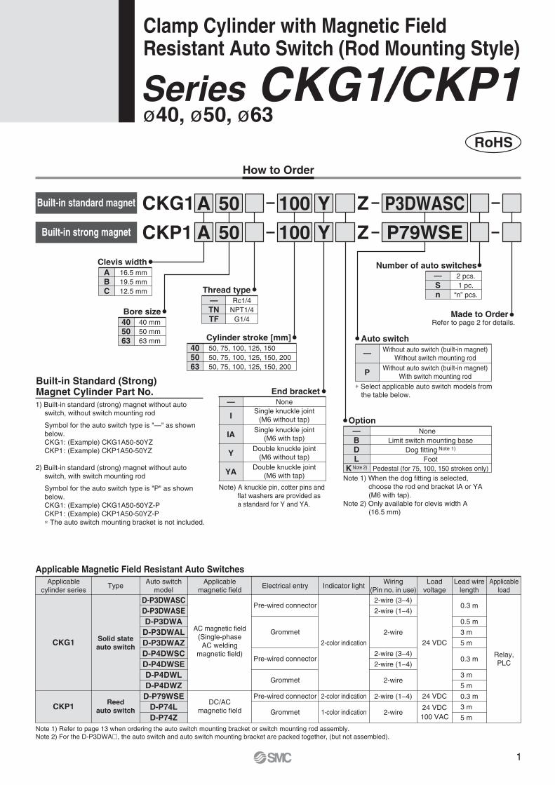
Clamp Cylinder with Magnetic Field Resistant Auto Switch (Rod Mounting Style)
ø40, ø50, ø63Series CKG1/CKP1
How to Order
D-P3DWASC
D-P3DWASE
D-P3DWA
D-P3DWAL
D-P3DWAZ
D-P4DWSC
D-P4DWSE
D-P4DWL
D-P4DWZ
D-P79WSE
D-P74L
D-P74Z
TypeApplicable
cylinder series
Auto switch
model
Applicable
magnetic fieldElectrical entry
AC magnetic field
(Single-phase
AC welding
magnetic field)
DC/AC
magnetic field
Indicator lightLoad
voltage
2-wire (1−4)
2-wire
24 VDC
24 VDC
24 VDC
100 VAC
Relay,
PLC
Applicable
load
Pre-wired connector
Grommet
2-color indication
2-color indication
1-color indication
Wiring
(Pin no. in use)
Solid state
auto switch
Reed
auto switch
CKG1
CKP1
Lead wire
length
0.3 m
3 m
5 m
Note 1) Refer to page 13 when ordering the auto switch mounting bracket or switch mounting rod assembly.
Note 2) For the D-P3DWA�, the auto switch and auto switch mounting bracket are packed together, (but not assembled).
Applicable Magnetic Field Resistant Auto Switches
CKG1Built-in standard magnet
405063
Cylinder stroke [mm]
50, 75, 100, 125, 150
50, 75, 100, 125, 150, 200
50, 75, 100, 125, 150, 200
A Y100
CKP1
Z
ZBuilt-in strong magnet
50
50A Y100 P79WSE
None
End bracket
I
IA
Y
YA
—Single knuckle joint
(M6 without tap)
Single knuckle joint
(M6 with tap)
Double knuckle joint
(M6 without tap)
Double knuckle joint
(M6 with tap)
Number of auto switches
Sn
— 2 pcs.
1 pc.
“n” pcs.
Auto switch
P
—Without auto switch (built-in magnet)
Without switch mounting rod
Without auto switch (built-in magnet)
With switch mounting rod
∗ Select applicable auto switch models from
the table below.
Note) A knuckle pin, cotter pins and
flat washers are provided as
a standard for Y and YA.
1) Built-in standard (strong) magnet without auto
switch, without switch mounting rod
Symbol for the auto switch type is "—" as shown
below.
CKG1: (Example) CKG1A50-50YZ
CKP1: (Example) CKP1A50-50YZ
2) Built-in standard (strong) magnet without auto
switch, with switch mounting rod
Symbol for the auto switch type is "P" as shown
below.
CKG1: (Example) CKG1A50-50YZ-P
CKP1: (Example) CKP1A50-50YZ-P
∗ The auto switch mounting bracket is not included.
Built-in Standard (Strong) Magnet Cylinder Part No.
P3DWASC
None
Option
BDL
K Note 2)
—Limit switch mounting base
Dog fitting Note 1)
Foot
Pedestal (for 75, 100, 150 strokes only)
Note 1) When the dog fitting is selected,
choose the rod end bracket IA or YA
(M6 with tap).
Note 2) Only available for clevis width A
(16.5 mm)
Refer to page 2 for details.Made to Order
ABC
16.5 mm
19.5 mm
12.5 mm
Clevis width
405063
40 mm
50 mm
63 mm
Bore size
Thread type
TNTF
— Rc1/4
NPT1/4
G1/4
Pre-wired connector
Grommet
Pre-wired connector
Grommet
2-wire (3−4)
2-wire (1−4)
2-wire
2-wire (3−4)
2-wire (1−4)
2-wire
0.3 m
0.5 m
3 m
5 m
0.3 m
3 m
5 m
1
CKG1
CKP1
Series CK�1
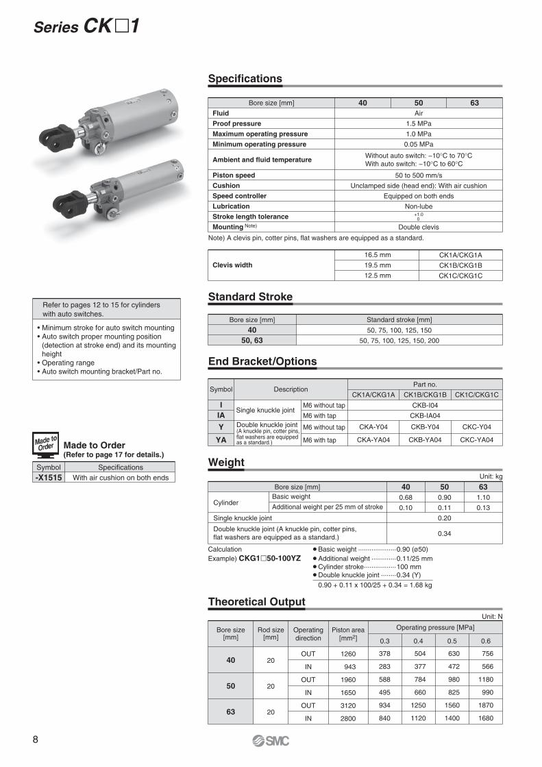
Made to Order(Refer to page 17 for details.)
Symbol Specifications
With air cushion on both ends-X1515
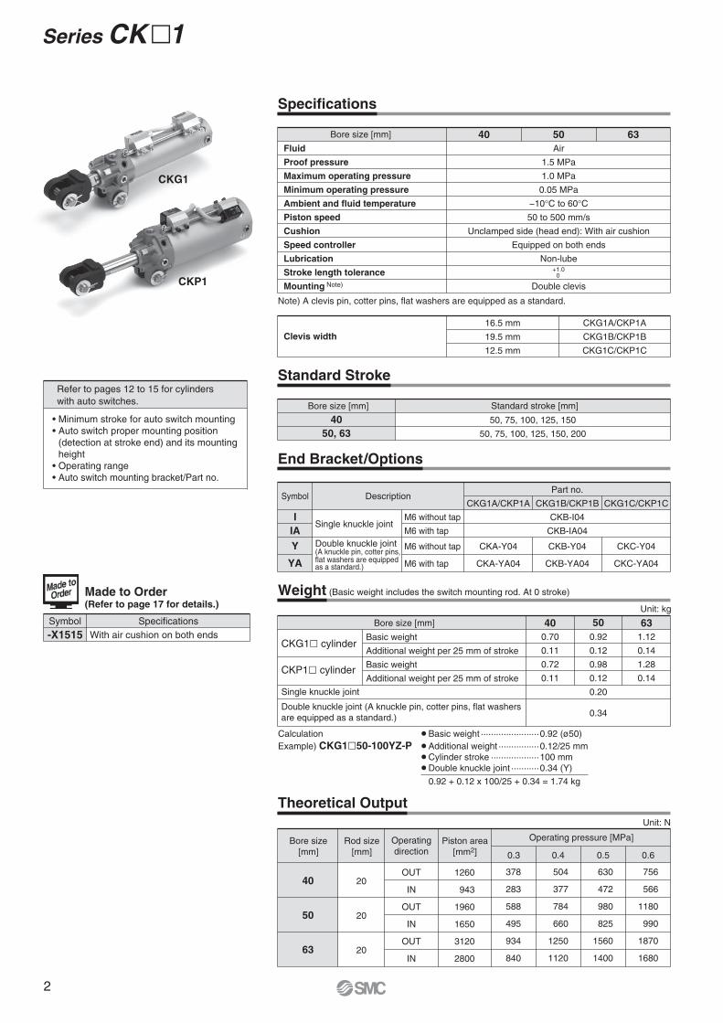
Standard Stroke
40
50, 63
50, 75, 100, 125, 150
50, 75, 100, 125, 150, 200
Theoretical Output
Operating
direction
Unit: N
40
50
63
20
20
20
OUT
IN
OUT
IN
OUT
IN
1260
943
1960
1650
3120
2800
0.6
Specifications
Clevis width
Note) A clevis pin, cotter pins, flat washers are equipped as a standard.
16.5 mm
19.5 mm
12.5 mm
CKG1A/CKP1A
CKG1B/CKP1B
CKG1C/CKP1C
Fluid
Proof pressure
Maximum operating pressure
Minimum operating pressure
Ambient and fluid temperature
Piston speed
Cushion
Speed controller
Lubrication
Stroke length tolerance
Mounting Note)
Air
1.5 MPa
1.0 MPa
0.05 MPa
−10°C to 60°C50 to 500 mm/s
Unclamped side (head end): With air cushion
Equipped on both ends
Non-lube
Double clevis
5040 63
+1.0 0
End Bracket/Options
I
IA
Y
YA
CKA-Y04
CKA-YA04
CKB-I04
CKB-IA04
CKB-Y04
CKB-YA04
Single knuckle joint
Double knuckle joint (A knuckle pin, cotter pins, flat washers are equipped as a standard.)
M6 without tap
M6 with tap
M6 without tap
M6 with tap
Symbol DescriptionPart no.
CKG1A/CKP1A CKG1B/CKP1B
CKC-Y04
CKC-YA04
CKG1C/CKP1C
Weight (Basic weight includes the switch mounting rod. At 0 stroke)
0.70
0.11
0.72
0.11
0.92
0.12
0.98
0.12
0.20
0.34
1.12
0.14
1.28
0.14
CKG1� cylinder
CKP1� cylinder
Basic weight
Additional weight per 25 mm of stroke
Basic weight
Additional weight per 25 mm of stroke
Single knuckle joint
Double knuckle joint (A knuckle pin, cotter pins, flat washers
are equipped as a standard.)
40 50 63
Unit: kg
Calculation ¡Basic weight ·······················0.92 (ø50)
Example) CKG1�50-100YZ-P ¡Additional weight ················0.12/25 mm
¡Cylinder stroke ···················100 mm
¡Double knuckle joint ···········0.34 (Y)
0.92 + 0.12 x 100/25 + 0.34 = 1.74 kg
756
566
1180
990
1870
1680
0.5
630
472
980
825
1560
1400
0.4
504
377
784
660
1250
1120
0.3
378
283
588
495
934
840
(detection at stroke end) and its mounting
height
Auto switch mounting bracket/Part no.
Refer to pages 12 to 15 for cylinders
with auto switches.
Bore size
[mm]
Operating pressure [MPa]Rod size
[mm]
Piston area
[mm2]
Bore size [mm]
Bore size [mm] Standard stroke [mm]
Bore size [mm]
2
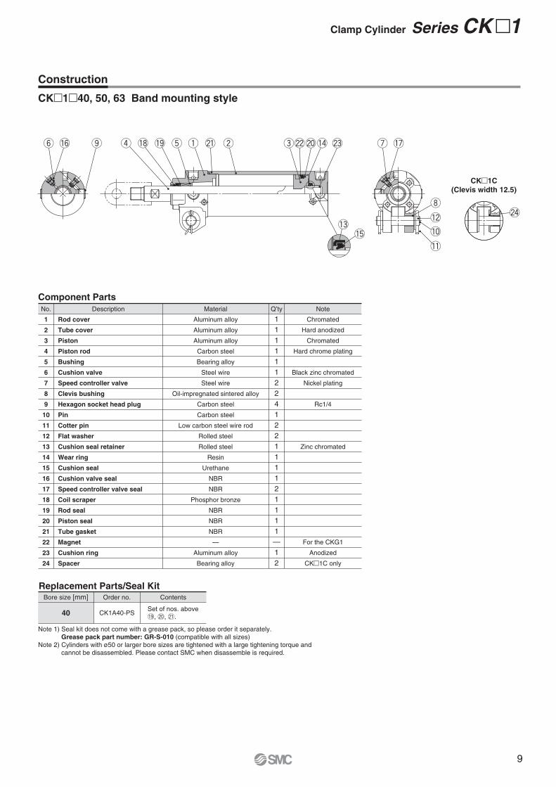
Clamp Cylinder Series CK�1
#0
y!6 @4@8 o u !7 @9 @6 @5 @7
#0
i
!2
!0
!1
q @1 w e @2 @0 !4y !6 @4 @3 o t!9!8r u !7 @8 @5 @6 @7
@9
i
!2
!0
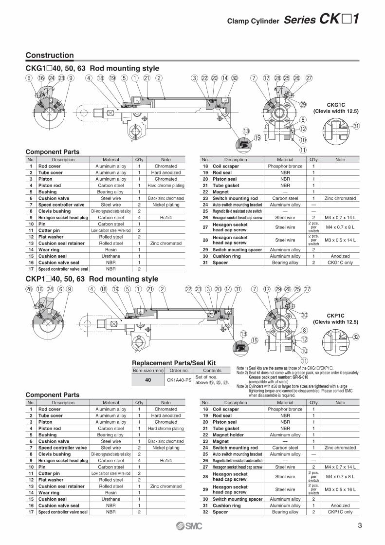
!1Component Parts
Rod cover
Tube cover
Piston
Piston rod
Bushing
Cushion valve
Speed controller valve
Clevis bushing
Hexagon socket head plug
Pin
Cotter pin
Flat washer
Cushion seal retainer
Wear ring
Cushion seal
Cushion valve seal
Speed controller valve seal
Aluminum alloy
Aluminum alloy
Aluminum alloy
Carbon steel
Bearing alloy
Steel wire
Steel wire
Oil-impregnated sintered alloy
Carbon steel
Carbon steel
Low carbon steel wire rod
Rolled steel
Rolled steel
Resin
Urethane
NBR
NBR
1
1
1
1
1
1
2
2
4
1
2
2
1
1
1
1
2
Chromated
Hard anodized
Chromated
Hard chrome plating
Black zinc chromated
Nickel plating
Rc1/4
Zinc chromated
1
2
3
4
5
6
7
8
9
10
11
12
13
14
15
16
17
No. Description Material Q’ty Note
Component Parts
CKP1�40, 50, 63 Rod mounting style
Coil scraper
Rod seal
Piston seal
Tube gasket
Magnet
Switch mounting rod
Auto switch mounting bracket
Magnetic field resistant auto switch
Hexagon socket head cap screw
Hexagon socket head cap screw
Hexagon socket head cap screw
Switch mounting spacer
Cushion ring
Spacer
Phosphor bronze
NBR
NBR
NBR
—
Carbon steel
Aluminum alloy
—
Steel wire
Steel wire
Steel wire
Aluminum alloy
Aluminum alloy
Bearing alloy
1
1
1
1
1
1
—
—
2
2
1
2
2 pcs.per
switch
2 pcs.per
switch
2 pcs.per
switch
2 pcs.per
switch
Zinc chromated
M4 x 0.7 x 14 L
M4 x 0.7 x 8 L
M3 x 0.5 x 14 L
Anodized
CKG1C only
18
19
20
21
22
23
24
25
26
27
28
29
30
31
No. Description Material Q’ty Note
Rod cover
Tube cover
Piston
Piston rod
Bushing
Cushion valve
Speed controller valve
Clevis bushing
Hexagon socket head plug
Pin
Cotter pin
Flat washer
Cushion seal retainer
Wear ring
Cushion seal
Cushion valve seal
Speed controller valve seal
Aluminum alloy
Aluminum alloy
Aluminum alloy
Carbon steel
Bearing alloy
Steel wire
Steel wire
Oil-impregnated sintered alloy
Carbon steel
Carbon steel
Low carbon steel wire rod
Rolled steel
Rolled steel
Resin
Urethane
NBR
NBR
1
1
1
1
1
1
2
2
4
1
2
2
1
1
1
1
2
Chromated
Hard anodized
Chromated
Hard chrome plating
Black zinc chromated
Nickel plating
Rc1/4
Zinc chromated
1
2
3
4
5
6
7
8
9
10
11
12
13
14
15
16
17
No. Description Material Q’ty Note
Coil scraper
Rod seal
Piston seal
Tube gasket
Magnet holder
Magnet
Switch mounting rod
Auto switch mounting bracket
Magnetic field resistant auto switch
Hexagon socket head cap screw
Hexagon socket head cap screw
Hexagon socket head cap screw
Switch mounting spacer
Cushion ring
Spacer
Phosphor bronze
NBR
NBR
NBR
Aluminum alloy
—
Carbon steel
Aluminum alloy
—
Steel wire
Steel wire
Steel wire
Aluminum alloy
Aluminum alloy
Bearing alloy
1
1
1
1
1
1
1
—
—
2
2
1
2
Zinc chromated
M4 x 0.7 x 14 L
M4 x 0.7 x 8 L
M3 x 0.5 x 16 L
Anodized
CKP1C only
18
19
20
21
22
23
24
25
26
27
28
29
30
31
32
No. Description Material Q’ty Note
Note 1) Seal kits are the same as those of the CKG1�/CKP1�.Note 2) Seal kit does not come with a grease pack, so please order it separately.
Grease pack part number: GR-S-010 (compatible with all sizes)
Note 3) Cylinders with ø50 or larger bore sizes are tightened with a large tightening torque and cannot be disassembled. Please contact SMC when disassemble is required.
Bore size (mm) Order no. Contents
CK1A40-PS40
Replacement Parts/Seal Kit
Set of nos.
above !9, @0, @1.
!3!5
#1q @1 w e@2 @3 @0 !4t!9!8r
!3!5
Construction
CKG1�40, 50, 63 Rod mounting style
CKG1C
(Clevis width 12.5)
#1
CKP1C
(Clevis width 12.5)
#2
3
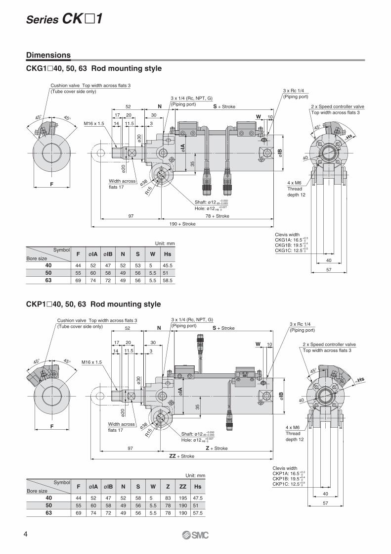
Dimensions
CKG1�40, 50, 63 Rod mounting style
CKP1�40, 50, 63 Rod mounting style
40
50
63
F
44
55
69
52
60
74
47
58
72
52
49
49
58
56
56
5
5.5
5.5
83
78
78
195
190
190
47.5
51
57.5
øIA øIB N S W Z ZZ Hs
40
50
63
Symbol
Bore size
44
55
69
52
60
74
47
58
72
52
49
49
53
56
56
5
5.5
5.5
45.5
51
58.5
F øIA øIB N S W Hs
Unit: mm
Symbol
Bore size
Unit: mm
R15
ø38
M16 x 1.5
97 78 + Stroke
190 + Stroke
3 x 1/4 (Rc, NPT, G)
(Piping port) S + StrokeN52
30
3
2017
14 11.5
Width across
flats 17
ø2
0
ø3
0
35
øIA
W 10
3 x Rc 1/4
(Piping port)
øIB
Shaft: ø12
Hole: ø12
−0.050d9−0.093
+0.027H8 0
40
≈Hs
45°
4 x M6
Thread
depth 12
2 x Speed controller valve
Top width across flats 3
57
40
Clevis widthCKP1A: 16.5CKP1B: 19.5CKP1C: 12.5
+0.30
+0.40
+0.50
3 x 1/4 (Rc, NPT, G)
(Piping port)
M16 x 1.5
97
ZZ + Stroke
Z + Stroke
Width across
flats 17
ø20
ø38
R15
35
øIA
3 x Rc 1/4
(Piping port)
øIB
10W
S + StrokeN52
30
11.5
2017
14
ø30
3
Shaft: ø12
Hole: ø12
−0.050d9−0.093
+0.027H8 0
40
45°
2 x Speed controller valve
Top width across flats 3
57
40
Clevis widthCKG1A: 16.5CKG1B: 19.5CKG1C: 12.5
≈Hs
+0.30
+0.40
+0.50
4 x M6
Thread
depth 12
45° 45°
F
Cushion valve Top width across flats 3
(Tube cover side only)
45° 45°
F
Cushion valve Top width across flats 3
(Tube cover side only)
Series CK�1
4

5
RoHS
Refer to page 8 for details.
Made to Order
CK1
ABC
16.5 mm
19.5 mm
12.5 mm
Clevis width
405063
Cylinder stroke [mm]
50, 75, 100, 125, 150
50, 75, 100, 125, 150, 200
50, 75, 100, 125, 150, 200
A Y100 Z
Z
None
End bracket
Note) A knuckle pin, cotter pins and flat washers are provided
as a standard for Y and YA.
IIAY
YA
—Single knuckle joint (M6 without tap)
Single knuckle joint (M6 with tap)
Double knuckle joint (M6 without tap)
Double knuckle joint (M6 with tap)
A
50
Y100
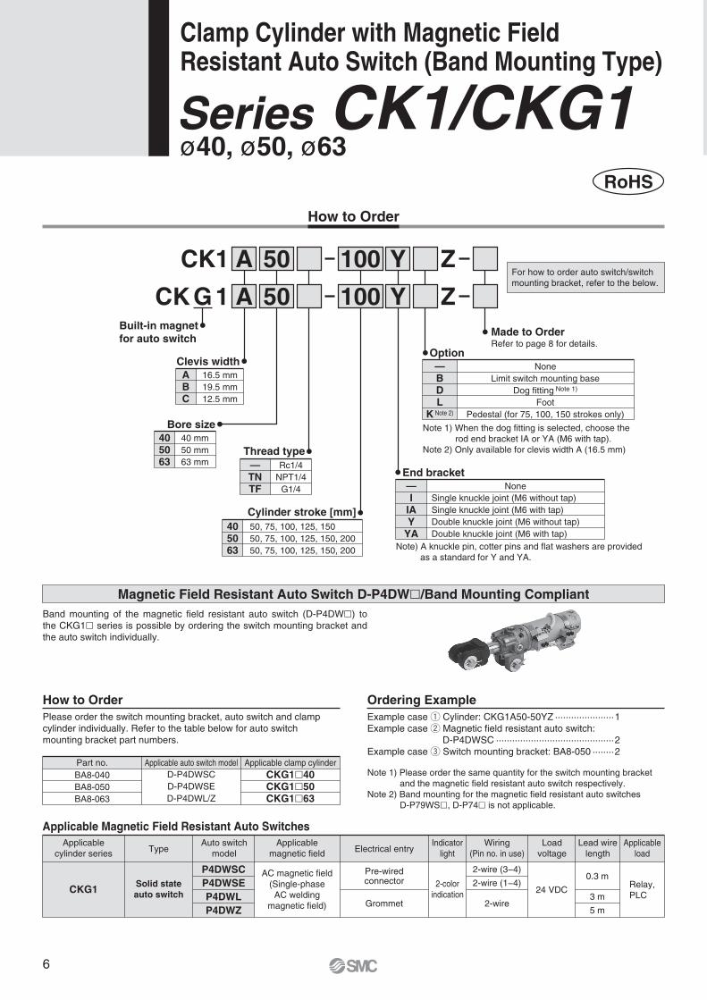
Magnetic Field Resistant Auto Switch D-P4DW�/Band Mounting Compliant
Please order the switch mounting bracket, auto switch and clamp
cylinder individually. Refer to the table below for auto switch
mounting bracket part numbers.
How to Order
Example case q Cylinder: CKG1A50-50YZ ······················1
Example case w Magnetic field resistant auto switch:
D-P4DWSC ············································2
Example case e Switch mounting bracket: BA8-050 ········2
Note 1) Please order the same quantity for the switch mounting bracket
and the magnetic field resistant auto switch respectively.
Note 2) Band mounting for the magnetic field resistant auto switches
D-P79WS�, D-P74� is not applicable.
Ordering Example
Part no. Applicable auto switch model Applicable clamp cylinder
BA8-040
BA8-050
BA8-063
D-P4DWSC
D-P4DWSE
D-P4DWL/Z
CKG1�40CKG1�50CKG1�63
TypeApplicable
cylinder series
Auto switch
model
P4DWSC
P4DWSE
P4DWL
P4DWZ
Applicable
magnetic fieldElectrical entry
AC magnetic field
(Single-phase
AC welding
magnetic field)
Indicator
light
Load
voltage
2-wire (3−4)
2-wire (1−4)
2-wire
24 VDCRelay,
PLC
Applicable
load
Applicable Magnetic Field Resistant Auto Switches
Pre-wiredconnector
Grommet
2-color
indication
Wiring
(Pin no. in use)
Solid state
auto switchCKG1
Lead wire
length
0.3 m
3 m
5 m
50
For how to order auto switch/switch
mounting bracket, refer to the below.
Band mounting of the magnetic field resistant auto switch (D-P4DW�) to
the CKG1� series is possible by ordering the switch mounting bracket and
the auto switch individually.
ø40, ø50, ø63Series CK1/CKG1
How to Order
None
Option
BDL
K Note 2)
—Limit switch mounting base
Dog fitting Note 1)
Foot
Pedestal (for 75, 100, 150 strokes only)
Note 1) When the dog fitting is selected, choose the
rod end bracket IA or YA (M6 with tap).
Note 2) Only available for clevis width A (16.5 mm)Thread type
—TNTF
Rc1/4
NPT1/4
G1/4
Clamp Cylinder with Magnetic Field Resistant Auto Switch (Band Mounting Type)
405063
40 mm
50 mm
63 mm
Bore size
1CK GBuilt-in magnet
for auto switch
6
ABC
16.5 mm
19.5 mm
12.5 mm
Clevis width
405063
Cylinder stroke [mm]
50, 75, 100, 125, 150
50, 75, 100, 125, 150, 200
50, 75, 100, 125, 150, 200
CK G 1 Z
None
End bracket
Note) A knuckle pin, cotter pins and flat washers are
provided as a standard for Y and YA.
IIAY
YA
—Single knuckle joint (M6 without tap)
Single knuckle joint (M6 with tap)
Double knuckle joint (M6 without tap)
Double knuckle joint (M6 with tap)
A
405063
40 mm
50 mm
63 mm
Bore size
Y100 M9BW50
ø40, ø50, ø63
RoHS
How to Order
None
Option
BDL
K Note 2)
—Limit switch mounting base
Dog fitting Note 1)
Foot
Pedestal (for 75, 100, 150 strokes only)
Note 1) When the dog fitting is selected, choose the
rod end bracket IA or YA (M6 with tap).
Note 2) Only available for clevis width A (16.5 mm)
Thread type
TNTF
— Rc1/4
NPT1/4
G1/4
2 pcs.
1 pc.
—S
Number of auto switches
Without auto switch
(Built-in magnet)
∗ For applicable auto switches,
refer to the table below.
∗ Auto switches are shipped together,
(but not assembled).
—
Auto switch
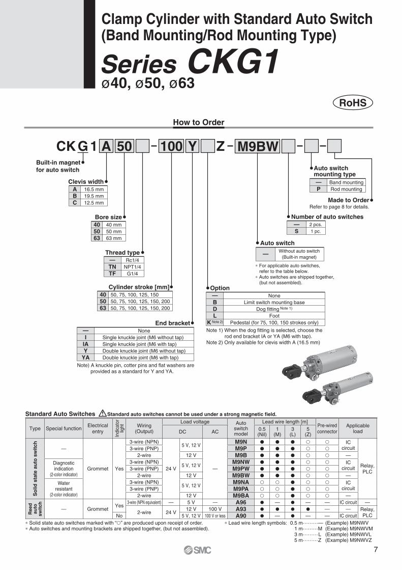
Series CKG1Clamp Cylinder with Standard Auto Switch (Band Mounting/Rod Mounting Type)
Built-in magnet
for auto switch
Made to Order
Band mounting
Rod mounting
Auto switchmounting type
P
—
Refer to page 8 for details.
Standard Auto Switches Standard auto switches cannot be used under a strong magnetic field.
Type Special functionElectrical
entry
Ind
ica
tor
ligh
t Wiring(Output)
Load voltage Auto switch model
Lead wire length [m]Pre-wired
connectorApplicable
loadDC AC0.5(Nil)
1(M)
3(L)
5(Z)
So
lid
sta
te a
uto
sw
itch
—
Grommet Yes
3-wire (NPN)
24 V
5 V, 12 V
—
M9N � � � � � ICcircuit
Relay,
PLC
3-wire (PNP) M9P � � � � �2-wire 12 V M9B � � � � � —
Diagnostic indication
(2-color indicator)
3-wire (NPN)5 V, 12 V
M9NW � � � � � ICcircuit3-wire (PNP) M9PW � � � � �
2-wire 12 V M9BW � � � � � —
Waterresistant
(2-color indicator)
3-wire (NPN)5 V, 12 V
M9NA � � � � � ICcircuit3-wire (PNP) M9PA � � � � �
2-wire 12 V M9BA � � � � � —
Reed
au
to
sw
itch
— GrommetYes
3-wire (NPN equivalent) — 5 V — A96 � — � — — IC circuit —
2-wire 24 V12 V 100 V A93 � � � � — — Relay,
PLCNo 5 V, 12 V 100 V or less A90 � — � — — IC circuit
∗ Solid state auto switches marked with “�” are produced upon receipt of order.∗ Auto switches and mounting brackets are shipped together, (but not assembled).
∗ Lead wire length symbols: 0.5 m……… — (Example) M9NWV 1 m……… M (Example) M9NWVM 3 m……… L (Example) M9NWVL 5 m……… Z (Example) M9NWVZ
7
Series CK�1
Made to Order(Refer to page 17 for details.)
Symbol Specifications
With air cushion on both ends-X1515
Specifications
Clevis width
16.5 mm
19.5 mm
12.5 mm
CK1A/CKG1A
CK1B/CKG1B
CK1C/CKG1C
Fluid
Proof pressure
Maximum operating pressure
Minimum operating pressure
Ambient and fluid temperature
Piston speed
Cushion
Speed controller
Lubrication
Stroke length tolerance
Mounting Note)
Air
1.5 MPa
1.0 MPa
0.05 MPa
Bore size [mm] 5040 63
50 to 500 mm/s
Unclamped side (head end): With air cushion
Equipped on both ends
Non-lube
Double clevis
Without auto switch: −10°C to 70°CWith auto switch: −10°C to 60°C
Note) A clevis pin, cotter pins, flat washers are equipped as a standard.
+1.0 0
Standard Stroke
40
50, 63
50, 75, 100, 125, 150
50, 75, 100, 125, 150, 200
Bore size [mm] Standard stroke [mm]
End Bracket/Options
I
IA
Y
YA
CKA-Y04
CKA-YA04
CKB-I04
CKB-IA04
CKB-Y04
CKB-YA04
CKC-Y04
CKC-YA04
Single knuckle jointM6 without tap
M6 with tap
M6 without tap
M6 with tap
Symbol DescriptionPart no.
CK1A/CKG1A CK1B/CKG1B CK1C/CKG1C
Weight
0.68
0.10
0.90
0.11
0.20
0.34
1.10
0.13Cylinder
Basic weight
Additional weight per 25 mm of stroke
Single knuckle joint
Double knuckle joint (A knuckle pin, cotter pins,
flat washers are equipped as a standard.)
Bore size [mm] 40 50 63
Unit: kg
Theoretical Output
Bore size[mm]
Operating
direction
Operating pressure [MPa]
Unit: N
40
50
63
Rod size[mm]
20
20
20
Piston area
[mm2]
OUT
IN
OUT
IN
OUT
IN
1260
943
1960
1650
3120
2800
0.6
756
566
1180
990
1870
1680
0.5
630
472
980
825
1560
1400
0.4
504
377
784
660
1250
1120
0.3
378
283
588
495
934
840
Calculation ¡Basic weight ····················0.90 (ø50)
Example) CKG1�50-100YZ ¡Additional weight ·············0.11/25 mm
¡Cylinder stroke·················100 mm
¡Double knuckle joint ········0.34 (Y)
0.90 + 0.11 x 100/25 + 0.34 = 1.68 kg
(detection at stroke end) and its mounting
height
Auto switch mounting bracket/Part no.
Double knuckle joint (A knuckle pin, cotter pins, flat washers are equipped as a standard.)
Refer to pages 12 to 15 for cylinders
with auto switches.
8
Construction
CK�1�40, 50, 63 Band mounting style
Rod cover
Tube cover
Piston
Piston rod
Bushing
Cushion valve
Speed controller valve
Clevis bushing
Hexagon socket head plug
Pin
Cotter pin
Flat washer
Cushion seal retainer
Wear ring
Cushion seal
Cushion valve seal
Speed controller valve seal
Coil scraper
Rod seal
Piston seal
Tube gasket
Magnet
Cushion ring
Spacer
Aluminum alloy
Aluminum alloy
Aluminum alloy
Carbon steel
Bearing alloy
Steel wire
Steel wire
Oil-impregnated sintered alloy
Carbon steel
Carbon steel
Low carbon steel wire rod
Rolled steel
Rolled steel
Resin
Urethane
NBR
NBR
Phosphor bronze
NBR
NBR
NBR
—
Aluminum alloy
Bearing alloy
1
1
1
1
1
1
2
2
4
1
2
2
1
1
1
1
2
1
1
1
1
—
1
2
Chromated
Hard anodized
Chromated
Hard chrome plating
Black zinc chromated
Nickel plating
Rc1/4
Zinc chromated
For the CKG1
Anodized
CK�1C only
1
2
3
4
5
6
7
8
9
10
11
12
13
14
15
16
17
18
19
20
21
22
23
24
Component PartsNo. Description Material Q’ty Note
Bore size [mm] Order no. Contents
CK1A40-PS40
Replacement Parts/Seal Kit
Note 1) Seal kit does not come with a grease pack, so please order it separately.
Grease pack part number: GR-S-010 (compatible with all sizes)
Note 2) Cylinders with ø50 or larger bore sizes are tightened with a large tightening torque and
cannot be disassembled. Please contact SMC when disassemble is required.
Set of nos. above
!9, @0, @1.
!3!5
r !8 !9 t q @1 w e @0!4 @3@2
i
!2
!0
!1
u !7y !6 o
CK�1C
(Clevis width 12.5)
@4
Clamp Cylinder Series CK�1
9
44
57
2 x ø3
ø12
−
0.0
50
d9−
0.0
93
15
17
19
ø30
Press-fit spring pin
ø3 x 38 L
2 x M6 thread depth 11 (for IA type)
17
ø30
19
15
20
Press-fit spring pin
ø3 x 38 L
2 x M6 thread depth 11 (for YA type)
ø12 +0.027H8 0 Shaft: ø12
−0.050d9−0.093
Hole: ø12 +0.027H8 0
20
25
60
45
15
17 2
020
2 x M6 thread depth 11 (for IA type)
19.5
−0.2
−0.5
35
18∗
57
40 A
60
45
15
17 2
020
2 x M6 thread depth 11 (for YA type)
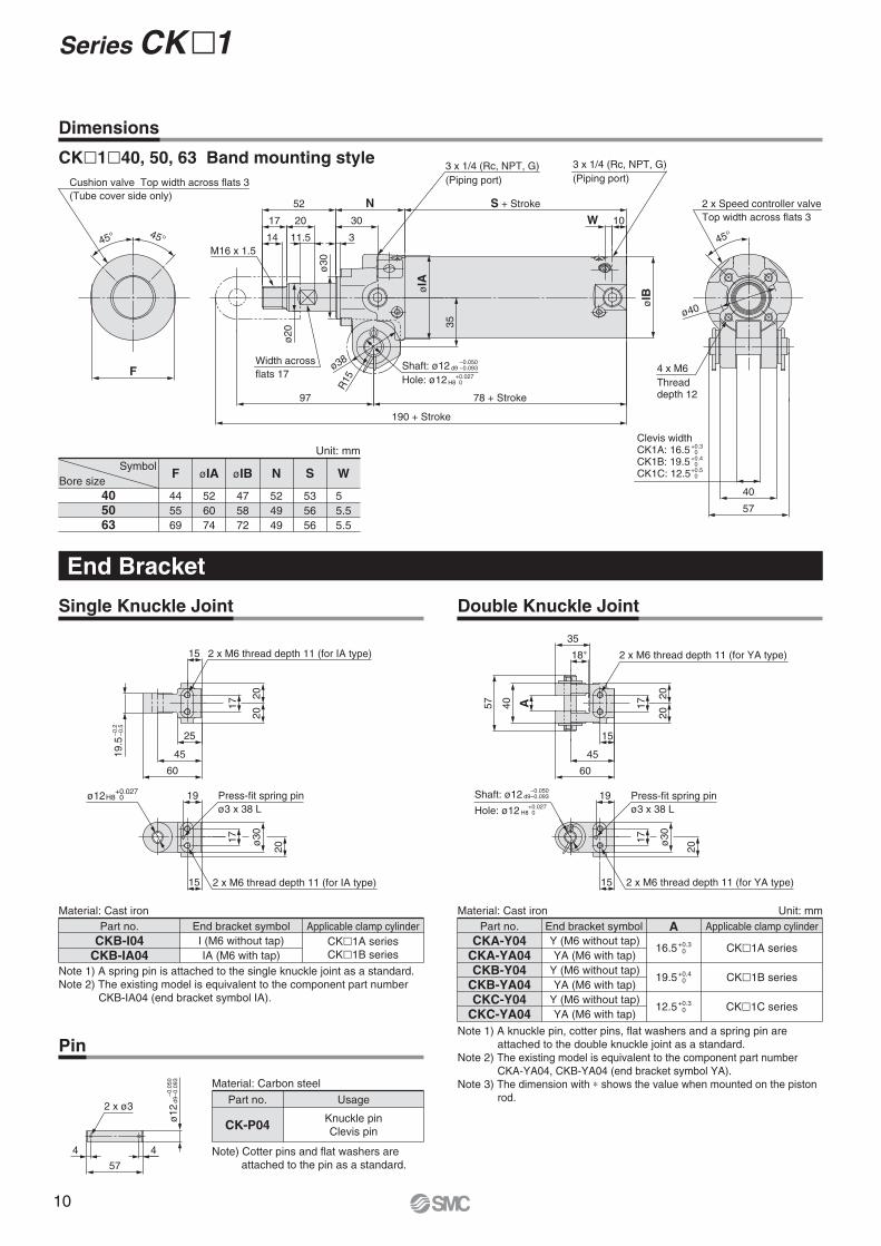
Dimensions
CK�1�40, 50, 63 Band mounting style
405063
Symbol
Bore size
44
55
69
52
60
74
47
58
72
52
49
49
53
56
56
5
5.5
5.5
Unit: mm
F øIA øIB N S W
Single Knuckle Joint
Pin
Double Knuckle Joint
Material: Cast iron
Part no. End bracket symbol Applicable clamp cylinder
CKB-I04CKB-IA04
CK�1A series
CK�1B series
I (M6 without tap)
IA (M6 with tap)
Material: Carbon steel
Material: Cast iron Unit: mm
Y (M6 without tap)
YA (M6 with tap)
Y (M6 without tap)
YA (M6 with tap)
Y (M6 without tap)
YA (M6 with tap)
Part no. End bracket symbol Applicable clamp cylinderACKA-Y04
CKA-YA04CKB-Y04
CKB-YA04CKC-Y04
CKC-YA04
CK�1A series
CK�1B series
CK�1C series
End Bracket
Part no. Usage
CK-P04Knuckle pin
Clevis pin
Note) Cotter pins and flat washers are
attached to the pin as a standard.
45°
4 x M6
Thread depth 12
ø40
57
40
2 x Speed controller valve
Top width across flats 3
Clevis widthCK1A: 16.5CK1B: 19.5CK1C: 12.5
+0.30
+0.40
+0.50
Note 1) A knuckle pin, cotter pins, flat washers and a spring pin are
attached to the double knuckle joint as a standard.
Note 2) The existing model is equivalent to the component part number
CKA-YA04, CKB-YA04 (end bracket symbol YA).
Note 3) The dimension with ∗ shows the value when mounted on the piston
rod.
16.5+0.30
19.5+0.40
12.5+0.30
Note 1) A spring pin is attached to the single knuckle joint as a standard.
Note 2) The existing model is equivalent to the component part number
CKB-IA04 (end bracket symbol IA).
45° 45°
Cushion valve Top width across flats 3
(Tube cover side only)
FShaft: ø12
Hole: ø12
−0.050d9 −0.093
+0.027H8 0
M16 x 1.5
190 + Stroke
78 + Stroke97
R15
Width across
flats 17
ø2
0
ø38
øIB
10W
S + StrokeN
30
3
52
2017
14 11.5
ø30
35
øIA
3 x 1/4 (Rc, NPT, G)
(Piping port)3 x 1/4 (Rc, NPT, G)
(Piping port)
Series CK�1
10
ø4
0
1758.75
75
1745
20
3097
45°
50
30.2
60
4.5
42.5
1520
4 x M5 x 0.8
Limit switchmounting base
Dog fitting
45
60
ø40
49
6
12 60
48
ø9
Foot
Clevis pin
57
34
16
50
30
15
809
5
KZZ
KL2
KYKS
35
45
KL1
15KX25
5
50KC
KZ
Kθ
Pedestal
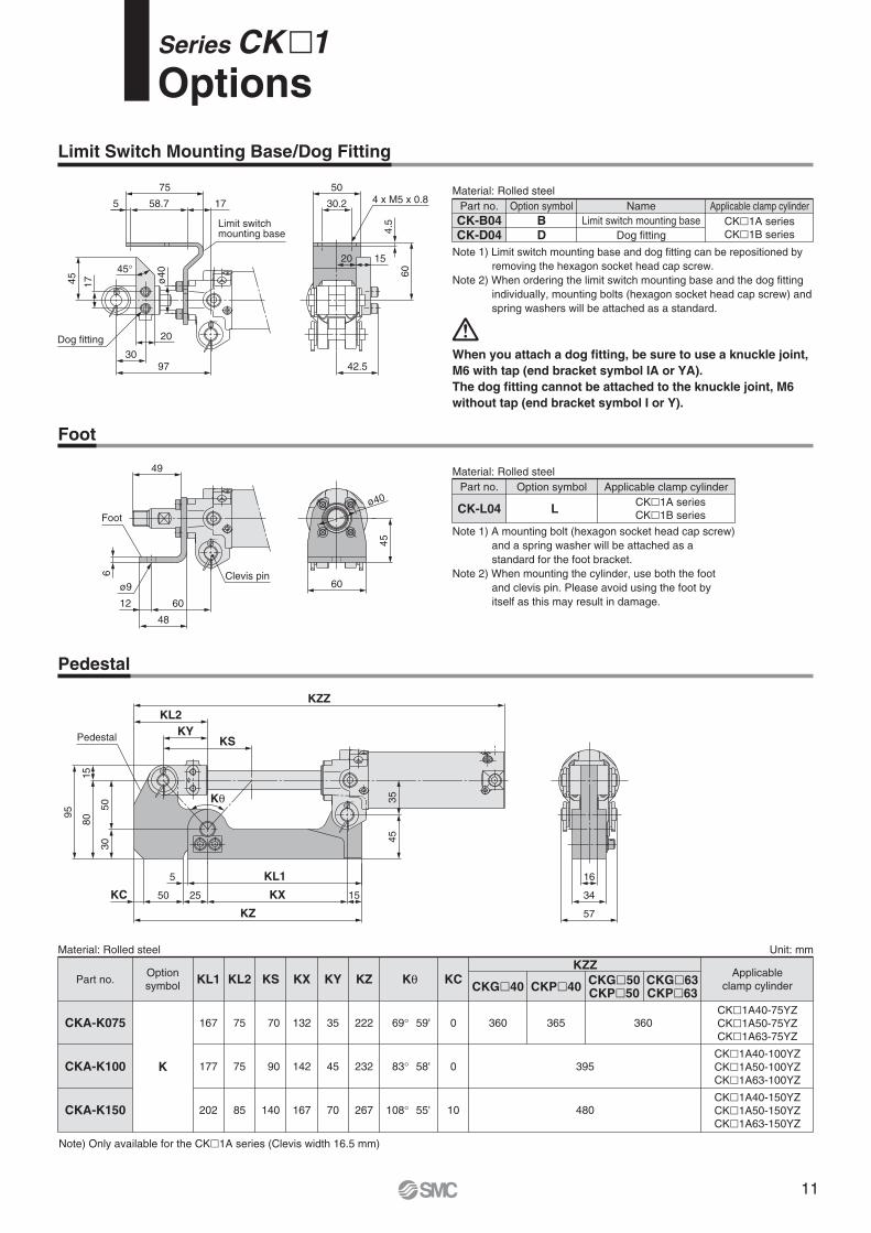
Series CK�1Options
Material: Rolled steel
Note 1) Limit switch mounting base and dog fitting can be repositioned by
removing the hexagon socket head cap screw.
Note 2) When ordering the limit switch mounting base and the dog fitting
individually, mounting bolts (hexagon socket head cap screw) and
spring washers will be attached as a standard.
Part no. Name Applicable clamp cylinder
CK-B04CK-D04
Option symbol
BD
CK�1A series
CK�1B series
Limit switch mounting base
Dog fitting
When you attach a dog fitting, be sure to use a knuckle joint,
M6 with tap (end bracket symbol IA or YA).
The dog fitting cannot be attached to the knuckle joint, M6
without tap (end bracket symbol I or Y).
Foot
Pedestal
Material: Rolled steel
Material: Rolled steel Unit: mm
Part no.
CKA-K075
CKA-K100
CKA-K150
KZ
222
232
267
KY
35
45
70
KX
132
142
167
KS
70
90
140
KL2
75
75
85
KL1
167
177
202
Option
symbol
K
KC
0
0
10
KθCKG�40 CKP�40
KZZ
CKG�50CKP�50
CKG�63CKP�63
395
480
360 365 360
Applicable
clamp cylinder
CK�1A40-75YZ
CK�1A50-75YZ
CK�1A63-75YZ
CK�1A40-100YZ
CK�1A50-100YZ
CK�1A63-100YZ
CK�1A40-150YZ
CK�1A50-150YZ
CK�1A63-150YZ
69°
83°
108°
59'
58'
55'
Note 1) A mounting bolt (hexagon socket head cap screw)
and a spring washer will be attached as a
standard for the foot bracket.
Note 2) When mounting the cylinder, use both the foot
and clevis pin. Please avoid using the foot by
itself as this may result in damage.
Part no. Applicable clamp cylinder
CK-L04CK�1A series
CK�1B series
Option symbol
L
Limit Switch Mounting Base/Dog Fitting
Note) Only available for the CK�1A series (Clevis width 16.5 mm)
11
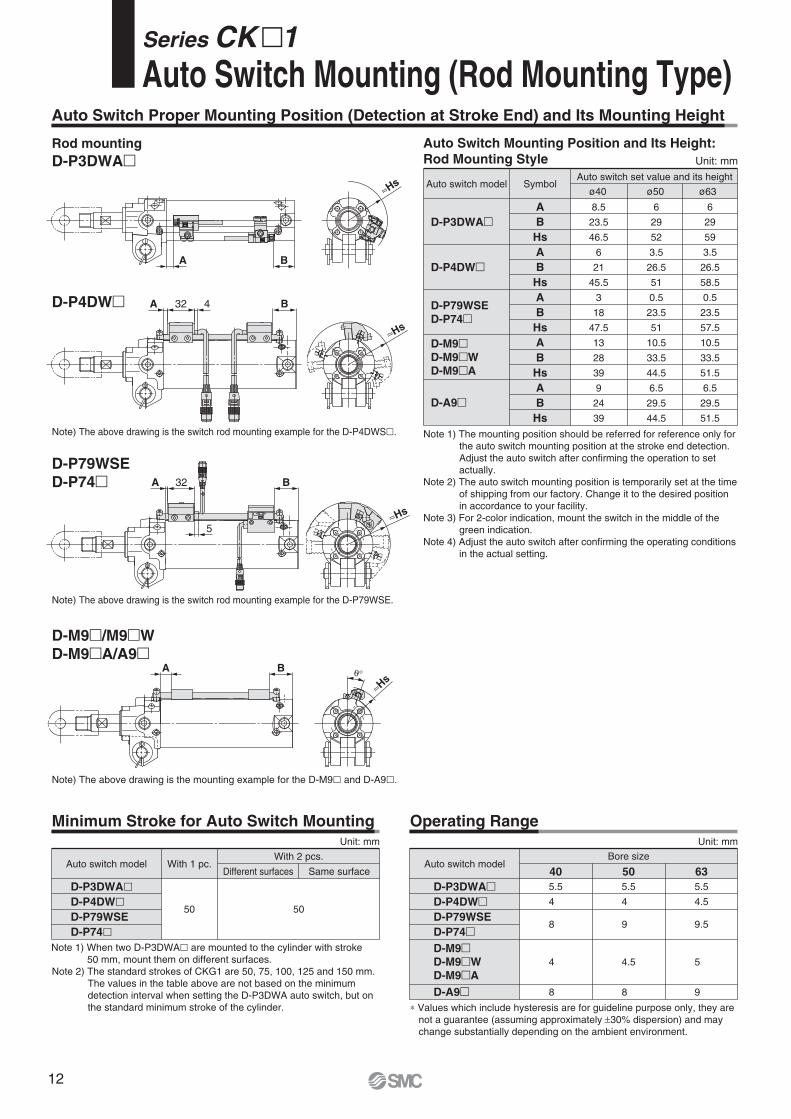
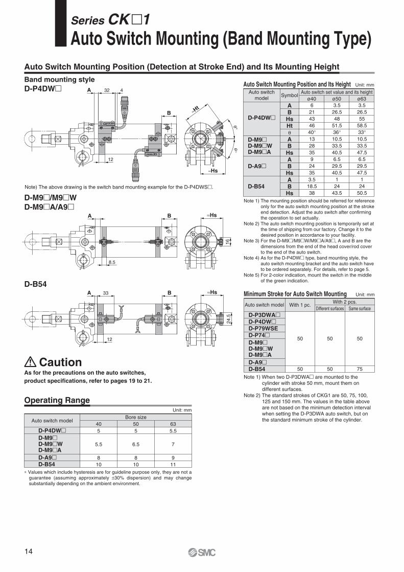
Auto Switch Proper Mounting Position (Detection at Stroke End) and Its Mounting Height
Series CK�1Auto Switch Mounting (Rod Mounting Type)
Note 1) The mounting position should be referred for reference only for
the auto switch mounting position at the stroke end detection.
Adjust the auto switch after confirming the operation to set
actually.
Note 2) The auto switch mounting position is temporarily set at the time
of shipping from our factory. Change it to the desired position
in accordance to your facility.
Note 3) For 2-color indication, mount the switch in the middle of the
green indication.
Note 4) Adjust the auto switch after confirming the operating conditions
in the actual setting.
Auto Switch Mounting Position and Its Height:
Rod Mounting Style Unit: mm
Minimum Stroke for Auto Switch MountingUnit: mm
Auto switch model
D-P3DWA�D-P4DW�D-P79WSE
D-P74�
With 1 pc.
50
Different surfaces Same surface
With 2 pcs.
50
Unit: mm
Operating Range
Note) The above drawing is the switch rod mounting example for the D-P79WSE.
≈Hs
∗ Values which include hysteresis are for guideline purpose only, they are
not a guarantee (assuming approximately ±30% dispersion) and may
change substantially depending on the ambient environment.
Note 1) When two D-P3DWA� are mounted to the cylinder with stroke
50 mm, mount them on different surfaces.
Note 2) The standard strokes of CKG1 are 50, 75, 100, 125 and 150 mm.
The values in the table above are not based on the minimum
detection interval when setting the D-P3DWA auto switch, but on
the standard minimum stroke of the cylinder.
Rod mounting
D-P3DWA�
D-P4DW�
Note) The above drawing is the switch rod mounting example for the D-P4DWS�.
≈Hs
≈Hs
D-P79WSE
D-P74�
D-M9�/M9�W
D-M9�A/A9�
Note) The above drawing is the mounting example for the D-M9� and D-A9�.
B32A
5
32 4 BA
A B
BA θ°
≈Hs
D-P4DW�
D-A9�
D-P3DWA�
D-P79WSE
D-P74�
D-M9�D-M9�W
D-M9�A
A
B
Hs
A
B
Hs
A
B
Hs
A
B
Hs
A
B
Hs
ø63ø50ø40Auto switch model Symbol
Auto switch set value and its height
Auto switch model
5.5
4
8
4
8
5.5
4
9
4.5
8
5.5
4.5
9.5
5
9
Bore size
D-P3DWA�D-P4DW�D-P79WSE
D-P74�
D-A9�
D-M9�D-M9�W
D-M9�A
40 50 63
6
29
59
3.5
26.5
58.5
0.5
23.5
57.5
10.5
33.5
51.5
6.5
29.5
51.5
6
29
52
3.5
26.5
51
0.5
23.5
51
10.5
33.5
44.5
6.5
29.5
44.5
8.5
23.5
46.5
6
21
45.5
3
18
47.5
13
28
39
9
24
39
12
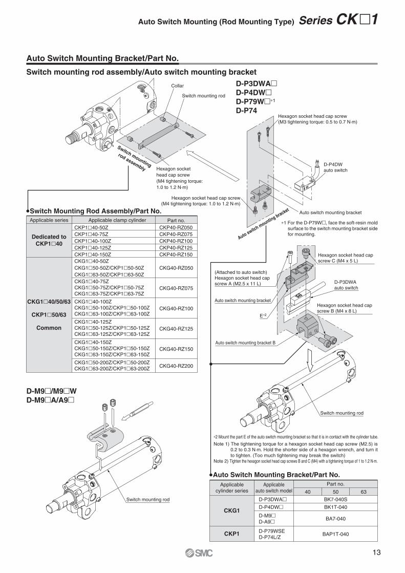
∗2 Mount the part E of the auto switch mounting bracket so that it is in contact with the cylinder tube.
Note 1) The tightening torque for a hexagon socket head cap screw (M2.5) is
0.2 to 0.3 N·m. Hold the shorter side of a hexagon wrench, and turn it
to tighten. (Too much tightening may break the switch)
Note 2) Tighten the hexagon socket head cap screws B and C (M4) with a tightening torque of 1 to 1.2 N·m.
Switch mounting rod
Switch mounting rod
D-M9�/M9�W
D-M9�A/A9�
(Attached to auto switch)
Hexagon socket head cap
screw A (M2.5 x 11 L)
Auto switch mounting bracket
E∗2
Auto switch mounting bracket B
Hexagon socket head cap
screw B (M4 x 8 L)
D-P3DWA
auto switch
Hexagon socket head cap
screw C (M4 x 5 L)
Auto switch m
ounting bracket
Hexagon socket head cap screw
(M3 tightening torque: 0.5 to 0.7 N·m)
D-P4DW
auto switch
Hexagon socket head cap screw
(M4 tightening torque: 1.0 to 1.2 N·m)
Auto switch mounting bracket
∗1 For the D-P79W�, face the soft-resin mold
surface to the switch mounting bracket side
for mounting.
Switch Mounting Rod Assembly/Part No.
CKP40-RZ050
CKP40-RZ075
CKP40-RZ100
CKP40-RZ125
CKP40-RZ150
CKG40-RZ050
CKG40-RZ075
CKG40-RZ100
CKG40-RZ125
CKG40-RZ150
CKG40-RZ200
Applicable clamp cylinderApplicable series Part no.
CKP1�40-50Z
CKP1�40-75Z
CKP1�40-100Z
CKP1�40-125Z
CKP1�40-150Z
CKG1�40-150Z
CKG1�50-150Z/CKP1�50-150Z
CKG1�63-150Z/CKP1�63-150Z
CKG1�50-200Z/CKP1�50-200Z
CKG1�63-200Z/CKP1�63-200Z
CKG1�40-50Z
CKG1�50-50Z/CKP1�50-50Z
CKG1�63-50Z/CKP1�63-50Z
CKG1�40-75Z
CKG1�50-75Z/CKP1�50-75Z
CKG1�63-75Z/CKP1�63-75Z
CKG1�40-100Z
CKG1�50-100Z/CKP1�50-100Z
CKG1�63-100Z/CKP1�63-100Z
CKG1�40-125Z
CKG1�50-125Z/CKP1�50-125Z
CKG1�63-125Z/CKP1�63-125Z
Dedicated to
CKP1�40
CKG1�40/50/63
CKP1�50/63
Common
Switch mounting
rod assembly
Collar
Switch mounting rod
Hexagon socket
head cap screw
(M4 tightening torque:
1.0 to 1.2 N·m)
Auto Switch Mounting Bracket/Part No.
Switch mounting rod assembly/Auto switch mounting bracket
Auto Switch Mounting Bracket/Part No.
Applicable
cylinder series
Applicable
auto switch model
Part no.
635040
BA7-040D-M9�D-A9�
CKP1 BAP1T-040D-P79WSE
D-P74L/Z
CKG1
BK7-040S
BK1T-040
D-P3DWA�D-P4DW�
D-P3DWA�D-P4DW�D-P79W�∗1
D-P74
Auto Switch Mounting (Rod Mounting Type) Series CK�1
13
D-B54
24.5
≈Hs
≈Hs
16
B33A
12
A
8.5
B
B
4A 32
12
≈Hs
≈Ht
θ°θ°
As for the precautions on the auto switches,
product specifications, refer to pages 19 to 21.
Caution
Auto Switch Mounting Position (Detection at Stroke End) and Its Mounting Height
Series CK�1Auto Switch Mounting (Band Mounting Type)
Minimum Stroke for Auto Switch Mounting Unit: mm
Auto switch model
D-A9�D-B54
With 1 pc.Different surfaces
50
50
50
50
50
75
Same surface
With 2 pcs.
Note 1) The mounting position should be referred for reference
only for the auto switch mounting position at the stroke
end detection. Adjust the auto switch after confirming
the operation to set actually.
Note 2) The auto switch mounting position is temporarily set at
the time of shipping from our factory. Change it to the
desired position in accordance to your facility.
Note 3) For the D-M9�/M9�W/M9�A/A9�, A and B are the
dimensions from the end of the head cover/rod cover
to the end of the auto switch.
Note 4) As for the D-P4DW� type, band mounting style, the
auto switch mounting bracket and the auto switch have
to be ordered separately. For details, refer to page 5.
Note 5) For 2-color indication, mount the switch in the middle
of the green indication.
Auto Switch Mounting Position and Its Height Unit: mm
Auto switch
model
D-A9�
D-B54
Symbol
AB
HsHtθAB
HsAB
HsAB
Hs
Auto switch set value and its height
ø63ø50ø40
D-M9�D-M9�WD-M9�A
D-M9�D-M9�WD-M9�A
D-P4DW�
D-P3DWA�D-P4DW�D-P79WSED-P74�
Note 1) When two D-P3DWA� are mounted to the
cylinder with stroke 50 mm, mount them on
different surfaces.
Note 2) The standard strokes of CKG1 are 50, 75, 100,
125 and 150 mm. The values in the table above
are not based on the minimum detection interval
when setting the D-P3DWA auto switch, but on
the standard minimum stroke of the cylinder.
Band mounting style
D-P4DW�
Note) The above drawing is the switch band mounting example for the D-P4DWS�.
Unit: mm
Auto switch model
5
5.5
8
10
5
6.5
8
10
Bore size
D-P4DW�
D-A9�D-B54
D-M9�D-M9�WD-M9�A
40 50
5.5
7
9
11
63
Operating Range
∗ Values which include hysteresis are for guideline purpose only, they are not a
guarantee (assuming approximately ±30% dispersion) and may change
substantially depending on the ambient environment.
D-M9�/M9�W
D-M9�A/A9�
3.5
26.5
55
58.5
33°10.5
33.5
47.5
6.5
29.5
47.5
1
24
50.5
3.5
26.5
48
51.5
36°10.5
33.5
40.5
6.5
29.5
40.5
1
24
43.5
6
21
43
46
40°13
28
35
9
24
35
3.5
18.5
38
14
Series CK�1
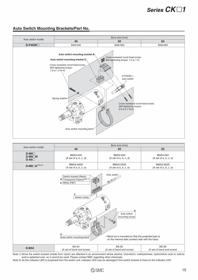
Auto Switch Mounting Brackets/Part No.
Note 1) Since the switch bracket (made from nylon) are affected in an environment where alcohol, chloroform, methylamines, hydrochloric acid or sulfuric
acid is splashed over, so it cannot be used. Please contact SMC regarding other chemicals.
Note 2) As the indicator LED is projected from the switch unit, indicator LED may be damaged if the switch bracket is fixed on the indicator LED.
Auto switch modelBore size [mm]
40 50 63
D-P4DW� BA8-040 BA8-050 BA8-063
Auto switch mounting bracket DCross recessed round head screw
(M4 tightening torque: 1.0 to 1.2)
Auto switch mounting bracket B
Cross recessed round head screw
(M3 tightening torque:
0.5 to 0.7 N·m)
D-P4DW�auto switch
Auto switch mounting band
Cross recessed round head screw
(M4 tightening torque:
1.0 to 1.2 N·m)
Spring washer
Auto switch modelBore size [mm]
40 50 63
D-M9�D-M9�WD-A9�
BMA3-040
(A set of a, b, c, d)
BMA3-050
(A set of a, b, c, d)
BMA3-063
(A set of a, b, c, d)
D-M9�ANote 2) BMA3-040S
(A set of a, b, c, e)
BMA3-050S
(A set of a, b, c, e)
BMA3-063S
(A set of a, b, c, e)
∗ Band (a) is mounted so that the projected part is
on the internal side (contact side with the tube).
Switch bracket (Resin)
Transparent (Nylon)Note 1)
White (PBT)
d
e
Auto switch mounting band
a
Auto switch
mounting screw
b
Switch holder
c
Auto switch
D-B54BA-04
(A set of band and screw)
BA-05
(A set of band and screw)
BA-06
(A set of band and screw)
15
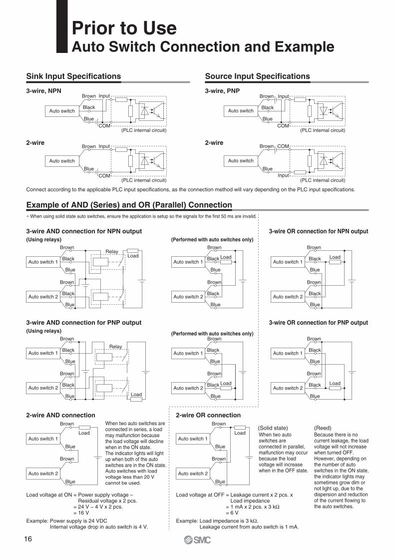
Prior to UseAuto Switch Connection and Example
Relay
Relay
Input
COM
COM
Input
COM
Input
COM
Input
2-wire OR connection2-wire AND connection
3-wire OR connection for PNP output
(Performed with auto switches only)(Using relays)
3-wire AND connection for PNP output
3-wire OR connection for NPN output
(Performed with auto switches only)(Using relays)
3-wire AND connection for NPN output
(PLC internal circuit)
(PLC internal circuit)
(PLC internal circuit)
(PLC internal circuit)
2-wire
3-wire, PNP
2-wire
3-wire, NPN
Load
Load
Load
Load Load
Load Load
Load
Blue
Black
Brown
Auto switch 2
Blue
Black
Brown
Auto switch 1
Blue
Black
Brown
Auto switch 2
Blue
Black
Brown
Auto switch 1
Blue
Black
Brown
Auto switch 2
Blue
Black
Brown
Auto switch 1
Blue
Black
Brown
Auto switch 2
Blue
Black
Brown
Auto switch 1
Blue
Brown
Auto switch 2
Blue
Brown
Auto switch 1
Blue
Black
Brown
Auto switch 2
Blue
Black
Brown
Auto switch 1
Blue
Brown
Auto switch 2
Blue
Brown
Auto switch 1
Blue
Black
Brown
Auto switch 2
Blue
Black
Brown
Auto switch 1
Blue
Brown
Blue
Brown
Blue
Black
Brown
Blue
Black
Brown
Auto switch
Auto switch
Auto switch
Auto switch
Example of AND (Series) and OR (Parallel) Connection
Sink Input Specifications Source Input Specifications
Load voltage at ON = Power supply voltage – Residual voltage x 2 pcs.
= 24 V − 4 V x 2 pcs.= 16 V
Example: Power supply is 24 VDCInternal voltage drop in auto switch is 4 V.
Load voltage at OFF = Leakage current x 2 pcs. x Load impedance
= 1 mA x 2 pcs. x 3 kΩ= 6 V
Example: Load impedance is 3 kΩ.Leakage current from auto switch is 1 mA.
(Solid state) (Reed)When two auto switches are connected in series, a load may malfunction because the load voltage will decline when in the ON state.The indicator lights will light up when both of the auto switches are in the ON state.Auto switches with load
voltage less than 20 V
cannot be used.
When two auto switches are connected in parallel, malfunction may occur because the load voltage will increase when in the OFF state.
Because there is no current leakage, the load voltage will not increase when turned OFF. However, depending on the number of auto switches in the ON state, the indicator lights may sometimes grow dim or not light up, due to the dispersion and reduction of the current flowing to the auto switches.
Connect according to the applicable PLC input specifications, as the connection method will vary depending on the PLC input specifications.
∗ When using solid state auto switches, ensure the application is setup so the signals for the first 50 ms are invalid.
16
Symbol
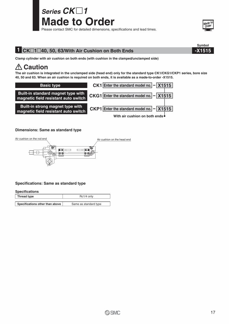
-X1515CK�1�40, 50, 63/With Air Cushion on Both Ends1
Clamp cylinder with air cushion on both ends (with cushion in the clamped/unclamped side)
X1515CK1 Enter the standard model no.
X1515Enter the standard model no.
X1515Enter the standard model no.
CKG1Built-in standard magnet type with
magnetic field resistant auto switch
CKP1Built-in strong magnet type with
magnetic field resistant auto switch
Basic type
With air cushion on both ends
The air cushion is integrated in the unclamped side (head end) only for the standard type CK1/CKG1/CKP1 series, bore size
40, 50 and 63. When an air cushion is required on both ends, it is available as a made-to-order -X1515.
Caution
Specifications
Rc1/4 only
Same as standard typeSpecifications other than above
Thread type
Air cushion on the rod end Air cushion on the head end
Dimensions: Same as standard type
Specifications: Same as standard type
Series CK �1 Made to OrderPlease contact SMC for detailed dimensions, specifications and lead times.
17
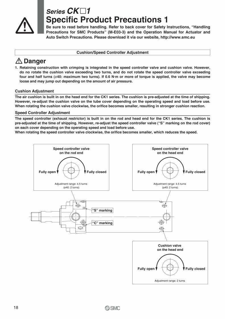
Cushion/Speed Controller Adjustment
1. Retaining construction with crimping is integrated in the speed controller valve and cushion valve. However, do no rotate the cushion valve exceeding two turns, and do not rotate the speed controller valve exceeding four and half turns (ø40: maximum two turns). If 0.6 N·m or more of torque is applied, the valve may become loose and may jump out depending on the amount of air pressure.
Danger
Speed controller valve
on the rod end
Adjustment range: 4.5 turns
(ø40: 2 turns)
Fully closedFully open
sc
Speed controller valve
on the head end
Adjustment range: 4.5 turns
(ø40: 2 turns)
Fully closedFully open
Cushion valve
on the head end
Adjustment range: 2 turns
Fully closedFully open
“S” marking
“C” marking
Cushion AdjustmentThe air cushion is built in on the head end for the CK1 series. The cushion is pre-adjusted at the time of shipping. However, re-adjust the cushion valve on the tube cover depending on the operating speed and load before use. When rotating the cushion valve clockwise, the orifice becomes smaller, resulting in stronger cushion reaction.
Speed Controller AdjustmentThe speed controller (exhaust restrictor) is built in on the rod and head end for the CK1 series. The cushion is pre-adjusted at the time of shipping. However, re-adjust the speed controller valve (“S” marking on the rod cover) on each cover depending on the operating speed and load before use.When rotating the speed controller valve clockwise, the orifice becomes smaller, which reduces the speed.
Be sure to read before handling. Refer to back cover for Safety Instructions, “Handling
Precautions for SMC Products” (M-E03-3) and the Operation Manual for Actuator and
Auto Switch Precautions. Please download it via our website, http://www.smc.eu
Series CK�1Specific Product Precautions 1
18
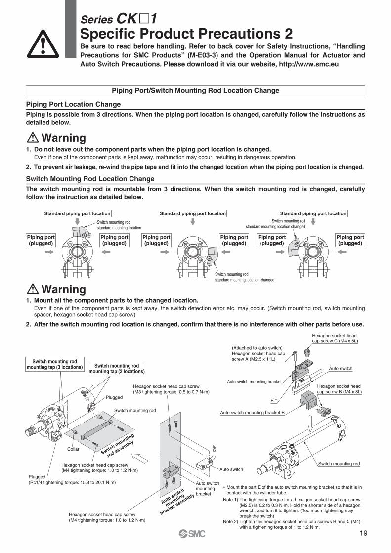
Piping Port Location Change
Piping is possible from 3 directions. When the piping port location is changed, carefully follow the instructions as
detailed below.
1. Do not leave out the component parts when the piping port location is changed.
Even if one of the component parts is kept away, malfunction may occur, resulting in dangerous operation.
2. To prevent air leakage, re-wind the pipe tape and fit into the changed location when the piping port location is changed.
Warning
Switch Mounting Rod Location Change
The switch mounting rod is mountable from 3 directions. When the switch mounting rod is changed, carefully
follow the instruction as detailed below.
1. Mount all the component parts to the changed location.
Even if one of the component parts is kept away, the switch detection error etc. may occur. (Switch mounting rod, switch mounting spacer, hexagon socket head cap screw)
2. After the switch mounting rod location is changed, confirm that there is no interference with other parts before use.
Warning
Piping Port/Switch Mounting Rod Location Change
Be sure to read before handling. Refer to back cover for Safety Instructions, “Handling
Precautions for SMC Products” (M-E03-3) and the Operation Manual for Actuator and
Auto Switch Precautions. Please download it via our website, http://www.smc.eu
Series CK�1Specific Product Precautions 2
Standard piping port location
Piping port(plugged)
Piping port(plugged)
Switch mounting rod
standard mounting location
Switch mounting rod
standard mounting location changed
Piping port(plugged)
Piping port(plugged)
Standard piping port location
Switch mounting rod
standard mounting location changed
Piping port(plugged)
Piping port(plugged)
Standard piping port location
Hexagon socket head cap screw
(M4 tightening torque: 1.0 to 1.2 N·m)
Hexagon socket head cap screw
(M3 tightening torque: 0.5 to 0.7 N·m)
Auto switch
Auto switch mountingbracket
Auto switch
mounting
bracket a
ssembly
Switch m
ounting
rod assembly
Plugged
(Rc1/4 tightening torque: 15.8 to 20.1 N·m)
Collar
Hexagon socket head cap screw
(M4 tightening torque: 1.0 to 1.2 N·m)
Plugged
Switch mounting rod
Switch mounting rodmounting tap (3 locations) Switch mounting rod
mounting tap (3 locations)
∗ Mount the part E of the auto switch mounting bracket so that it is in
contact with the cylinder tube.
Note 1) The tightening torque for a hexagon socket head cap screw
(M2.5) is 0.2 to 0.3 N·m. Hold the shorter side of a hexagon
wrench, and turn it to tighten. (Too much tightening may
break the switch)
Note 2) Tighten the hexagon socket head cap screws B and C (M4)
with a tightening torque of 1 to 1.2 N·m.
Hexagon socket head
cap screw C (M4 x 5L)
Auto switch
Auto switch mounting bracket
E ∗
Auto switch mounting bracket B
Hexagon socket head
cap screw B (M4 x 8L)
Switch mounting rod
(Attached to auto switch)
Hexagon socket head cap
screw A (M2.5 x 11L)
19

Handling
Magnetic field resistant auto switches D-P79WSE/D-P74�
are specifically for use with built-in strong magnet type
cylinders and are not compatible with general auto
switches or cylinders. Built-in strong magnet type
cylinders are labelled as follows.
Mounting
1. The minimum stroke for mounting magnetic field
resistant auto switches is 50 mm.
2. In order to fully use the capacity of magnetic field
resistant auto switches, strictly observe the
following precautions.
1) Do not allow the magnetic field to occur when the cylinder
piston is moving.
2) When a welding cable or welding gun electrodes are near
the cylinder, change the auto switch position to fall within
the operational ranges shown in the graphs on page 21, or
move the welding cable away from the cylinder.
3) Cannot be used in an environment where welding cables
surround the cylinder.
4) Please consult with SMC when a welding cable and welding
gun electrodes (something energised with secondary current)
are near multiple auto switches.
3. In an environment where spatter directly hits the
lead wire, cover the lead wire with protective
tubing.
Use protective tubing with inside diameter of ø8 or
more that has excellent heat resistance and
flexibility.
4. Be careful not to drop objects, make dents, or
apply excessive impact force when handling.
5. When operating two or more cylinders with
magnetic field resistant auto switches in parallel
and proximity, separate the auto switches from
other cylinder tubes by an additional 30 mm or
more.
6. Avoid wiring in a manner in which repeated
bending stress or tension is applied to lead wires.
7. Please consult with SMC regarding use in an
environment with constant water and coolant
splashing.
8. Be careful of the mounting direction of the mag-
netic field resistant auto switch D-P79WSE.
Be sure to face the soft-resin mold surface to the
switch mounting bracket side for mounting.
(Refer to page 12 for mounting example and the auto switch
guide for soft-resin mold surface.)
Wiring/Current and Voltage
1. Always connect the auto switch to the power
supply after the load has been connected.
2. Series connection
When auto switches are connected in series as
shown below:
Note that the voltage drop due to the internal resistance of the
LED increases.
Magnetic field resistant cylinder with built-in magnet
(For use with auto switch D-P7)
Load
Be sure to read before handling. Refer to back cover for Safety Instructions, “Handling
Precautions for SMC Products” (M-E03-3) and the Operation Manual for Actuator and
Auto Switch Precautions. Please download it via our website, http://www.smc.eu
Series CK�1Specific Product Precautions 3
20
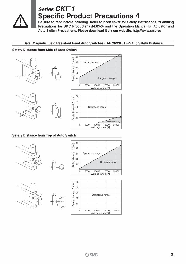
Safety Distance from Side of Auto Switch
Safety Distance from Top of Auto Switch
0 5000 10000 15000 20000
10
20
30
40
50
Welding current [A]
Sa
fety
dis
tan
ce
L1
[m
m]
0 5000 10000 15000 20000
10
20
30
40
50
Welding current [A]
Safe
ty d
ista
nce L
2 [m
m]
0 5000 10000 15000 20000
10
20
30
40
50
Welding current [A]
Safe
ty d
ista
nce L
2 [m
m]
0 5000 10000 15000 20000
10
20
30
40
50
Welding current [A]
Safe
ty d
ista
nce L
1 [
mm
]
L1
L2
L1
L1
L1
L2
L2L2
Data: Magnetic Field Resistant Reed Auto Switches (D-P79WSE, D-P74�) Safety Distance
Operational range
Dangerous range
Operational range
Dangerous range
Operational range
Dangerous range
Operational range
Be sure to read before handling. Refer to back cover for Safety Instructions, “Handling
Precautions for SMC Products” (M-E03-3) and the Operation Manual for Actuator and
Auto Switch Precautions. Please download it via our website, http://www.smc.eu
Series CK�1Specific Product Precautions 4
21
≈41.
5
≈38
45°45°M
ax. 26.5
41.2
26
12 +0.5+0.2
Speed controller valve Cushion valve
12
12
432
2034 + Stroke
70 + Stroke55
137 + Stroke
5612
9.5
25
ø28
R12
ø12
4
4
28
20
ø40
26
5
Width across
flats 36
M10 x 1.25
3 x Rc1/8
3 x Rc1/8
Shaft: ø10
Hole: ø10
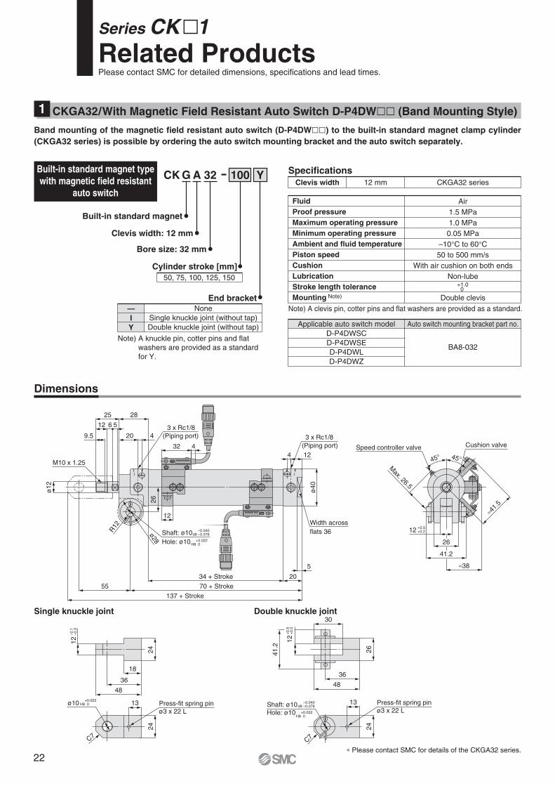
Dimensions
∗ Please contact SMC for details of the CKGA32 series.
Double knuckle jointSingle knuckle joint
24
13
C7
Press-fit spring pin
ø3 x 22 LShaft: ø10
Hole: ø10
–0.040d9 –0.076
+0.022H8 0
–0.040d9 –0.076
+0.022H8 0
18
36
48
24
12
–0
.1–
0.3
13
24
Press-fit spring pin
ø3 x 22 L
ø10 +0.022H8 0
C7
30
48
36
26
12
41.2
+0
.5+
0.2
CKGA32/With Magnetic Field Resistant Auto Switch D-P4DW�� (Band Mounting Style)1
CK G A 32 100 YBuilt-in standard magnet type
with magnetic field resistant
auto switch
Specifications
12 mm CKGA32 seriesClevis width
Note) A clevis pin, cotter pins and flat washers are provided as a standard.
Air
1.5 MPa
1.0 MPa
0.05 MPa
–10°C to 60°C50 to 500 mm/s
With air cushion on both ends
Non-lube
Double clevis
Fluid
Proof pressure
Maximum operating pressure
Minimum operating pressure
Ambient and fluid temperature
Piston speed
Cushion
Lubrication
Stroke length tolerance
Mounting Note)
+1.00
Built-in standard magnet
Clevis width: 12 mm
Bore size: 32 mm
Cylinder stroke [mm]
50, 75, 100, 125, 150
Applicable auto switch model
D-P4DWSC
D-P4DWSE
D-P4DWL
D-P4DWZ
Auto switch mounting bracket part no.
BA8-032
None
Single knuckle joint (without tap)
Double knuckle joint (without tap)
—
I
Y
End bracket
Note) A knuckle pin, cotter pins and flat
washers are provided as a standard
for Y.
Band mounting of the magnetic field resistant auto switch (D-P4DW��) to the built-in standard magnet clamp cylinder
(CKGA32 series) is possible by ordering the auto switch mounting bracket and the auto switch separately.
(Piping port)
(Piping port)
Series CK�1Related ProductsPlease contact SMC for detailed dimensions, specifications and lead times.
22
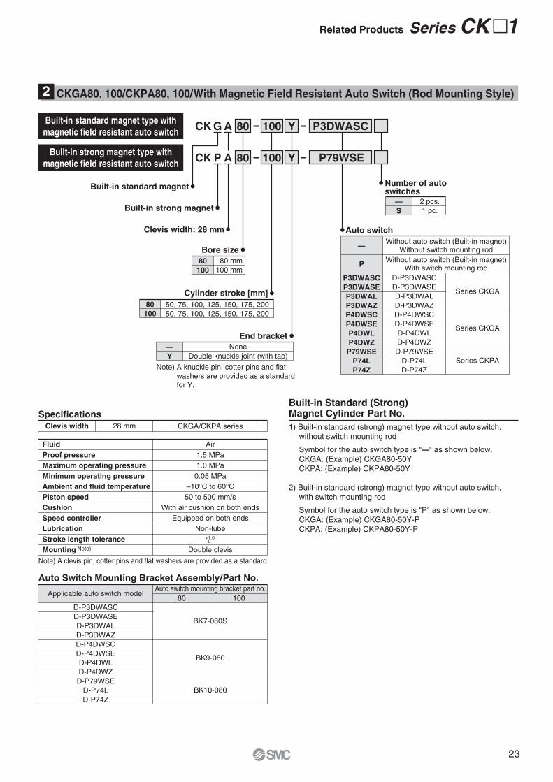
CKGA80, 100/CKPA80, 100/With Magnetic Field Resistant Auto Switch (Rod Mounting Style)2
P3DWASCCK G A 80 YBuilt-in standard magnet type with
magnetic field resistant auto switch
Specifications
28 mm CKGA/CKPA seriesClevis width
Note) A clevis pin, cotter pins and flat washers are provided as a standard.
Air
1.5 MPa
1.0 MPa
0.05 MPa
–10°C to 60°C50 to 500 mm/s
With air cushion on both ends
Equipped on both ends
Non-lube
Double clevis
Fluid
Proof pressure
Maximum operating pressure
Minimum operating pressure
Ambient and fluid temperature
Piston speed
Cushion
Speed controller
Lubrication
Stroke length tolerance
Mounting Note)
+1.0 0
1) Built-in standard (strong) magnet type without auto switch,
without switch mounting rod
Symbol for the auto switch type is "—" as shown below.
CKGA: (Example) CKGA80-50Y
CKPA: (Example) CKPA80-50Y
2) Built-in standard (strong) magnet type without auto switch,
with switch mounting rod
Symbol for the auto switch type is "P" as shown below.
CKGA: (Example) CKGA80-50Y-P
CKPA: (Example) CKPA80-50Y-P
Built-in standard magnet
Built-in strong magnet
Clevis width: 28 mm
100
P79WSECK P A 80 Y
2 pcs.
1 pc.
—
S
Number of autoswitches
Built-in strong magnet type with
magnetic field resistant auto switch100
80 mm
100 mm
80
100
Bore size
50, 75, 100, 125, 150, 175, 200
50, 75, 100, 125, 150, 175, 200
80
100
Cylinder stroke [mm]
Note) A knuckle pin, cotter pins and flat
washers are provided as a standard
for Y.
None
Double knuckle joint (with tap)
—
Y
End bracket
—
P
P3DWASC
P3DWASE
P3DWAL
P3DWAZ
P4DWSC
P4DWSE
P4DWL
P4DWZ
P79WSE
P74L
P74Z
Without auto switch (Built-in magnet)Without switch mounting rod
Without auto switch (Built-in magnet)With switch mounting rod
D-P3DWASC
D-P3DWASE
D-P3DWAL
D-P3DWAZ
D-P4DWSC
D-P4DWSE
D-P4DWL
D-P4DWZ
D-P79WSE
D-P74L
D-P74Z
Series CKGA
Series CKGA
Series CKPA
Auto switch
Built-in Standard (Strong) Magnet Cylinder Part No.
Auto Switch Mounting Bracket Assembly/Part No.
Applicable auto switch model
D-P3DWASC
D-P3DWASE
D-P3DWAL
D-P3DWAZ
D-P4DWSC
D-P4DWSE
D-P4DWL
D-P4DWZ
D-P79WSE
D-P74L
D-P74Z
Auto switch mounting bracket part no.
80 100
BK9-080
BK7-080S
BK10-080
Related Products Series CK�1
23
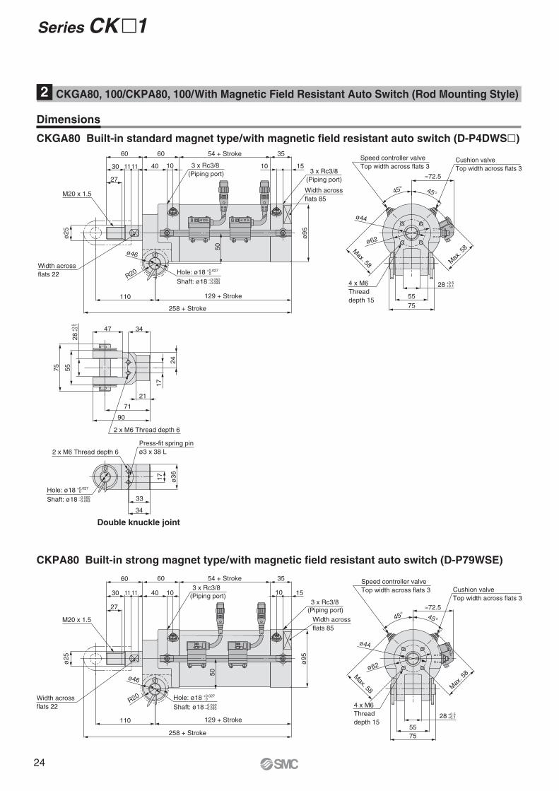
Dimensions
CKGA80 Built-in standard magnet type/with magnetic field resistant auto switch (D-P4DWS�)
CKPA80 Built-in strong magnet type/with magnetic field resistant auto switch (D-P79WSE)
Double knuckle joint
Hole: ø18 +0.027 0
Shaft: ø18 –0.050 –0.093
Hole: ø18 +0.027 0
Shaft: ø18 –0.050 –0.093
Hole: ø18 +0.027 0
Shaft: ø18 –0.050 –0.093
28 +0.5 +0.1
28
+0.5
+
0.1
17
24
3447
75
55
2 x M6 Thread depth 6
21
71
90
ø36
33
34
2 x M6 Thread depth 6
Press-fit spring pin
ø3 x 38 L
17
Speed controller valve
Top width across flats 3
≈72.5
45°
55
75
ø62
ø44
45°
Cushion valve
Top width across flats 3
4 x M6
Thread
depth 15
28 +0.5 +0.1
Speed controller valve
Top width across flats 3
≈72.5
45°
55
75
ø62
ø44
45°
Cushion valve
Top width across flats 3
4 x M6
Thread
depth 15
1111
ø46
27
ø2
5
110
258 + Stroke
30
60
50
R20
ø9
5
129 + Stroke
1510
3554 + Stroke
1040
60
SMC
Width across
flats 85
Width across
flats 22
SMC
M20 x 1.5
3 x Rc3/83 x Rc3/8
ø46
27
ø25
11
110
258 + Stroke
1130
60
50
R20
ø95
129 + Stroke
1510
3554 + Stroke
1040
60
Width across
flats 85
Width across
flats 22
M20 x 1.5
3 x Rc3/8
3 x Rc3/8
Max. 58 M
ax. 5
8
Max. 58 M
ax. 5
8
(Piping port)(Piping port)
(Piping port)
(Piping port)
Series CK�1
CKGA80, 100/CKPA80, 100/With Magnetic Field Resistant Auto Switch (Rod Mounting Style)2
24
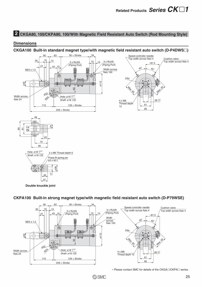
∗ Please contact SMC for details of the CKGA�/CKPA� series.
≈81.5
85
61
Max. 65 M
ax. 6
5
45° 45°
4 x M6
Thread depth 12
Speed controller needle
Top width across flats 4Cushion valve
Top width across flats 4
Double knuckle joint
4 x M6
Thread depth
12
Speed controller needle
Top width across flats 4
45° 45°
≈81.5
Max. 65
Cushion valve
Top width across flats 4
Max
. 65
61
85
85
61
90
70
25
24
48
ø38
37
32 17
Press-fit spring pin
ø5 x 40 L
2 x M6 Thread depth 6
28
+0.5
+
0.1
28 +0.5 +0.1
28 +0.5 +0.1
CKGA100 Built-in standard magnet type/with magnetic field resistant auto switch (D-P4DWS�)
CKPA100 Built-in strong magnet type/with magnetic field resistant auto switch (D-P79WSE)
101310
ø52
R24
259 + Stroke
ø1
12
50
ø3
0
129 + Stroke
56 + Stroke
SMC
SMC
Width across
flats 100
3 x Rc3/8
M24 x 1.5
3 x Rc3/830
63
43 1027
34
14
110
56
10 13
ø52
R24
259 + Stroke
110
ø112
50
ø30
129 + Stroke
27
30
56
43 10
63 56 + Stroke 34
1410
Width
across flats 100
3 x Rc3/8
M24 x 1.5
3 x Rc3/8
ø44
ø44
Dimensions
Hole: ø18 +0.027 0
Shaft: ø18 –0.050 –0.093
Hole: ø18 +0.027 0
Shaft: ø18 –0.050 –0.093
Hole: ø18 +0.027 0
Shaft: ø18 –0.050 –0.093
Width across
flats 24
Width across
flats 24
CKGA80, 100/CKPA80, 100/With Magnetic Field Resistant Auto Switch (Rod Mounting Style)2
(Piping Port)(Piping Port)
(Piping Port) (Piping Port)
Related Products Series CK�1
25
For details about this product, refer to the catalogue at www.smc.eu
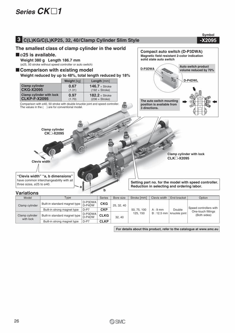
Series CK�1
Clamp cylinder
CK�-X2095
Clamp cylinder with lock
CLK�-X2095
VariationsModel Bore sizeSeriesType Stroke [mm] Clevis width End bracket Option
Clamp cylinder
Clamp cylinder
with lock
Built-in standard magnet type
Built-in strong magnet type
Built-in standard magnet type
Built-in strong magnet type
D-P3DWAD-P4DW
D-P3DWAD-P4DW
D-P7
D-P7
Speed controllers with
One-touch fittings
(Both sides)
Double
knuckle joint
A : 9 mm
B : 12.5 mm
25, 32, 40
32, 40
50, 75, 100
125, 150
CKG
CKP
CLKG
CLKP
Compact auto switch (D-P3DWA)
Setting part no. for the model with speed controller. Reduction in selecting and ordering labor.
The auto switch mounting position is available from 3 directions.
Clevis width
�ø25 is available.Weight 380 g Length 186.7 mm(ø25, 50 stroke without speed controller or auto switch)
�Comparison with existing modelWeight reduced by up to 48%, total length reduced by 18%
The smallest class of clamp cylinder in the world
Clamp cylinder
CKG-X2095
Comparison with ø40, 50 stroke with double knuckle joint and speed controller.The values in the ( ) are for conventional model.
Clamp cylinder with lock
CLKP-F-X2095
0.67(1.31)
0.97(1.70)
146.7 + Stroke
(192 + Stroke)
182.2 + Stroke
(236 + Stroke)
Length [mm]Weight [kg]
Symbol
-X2095C(L)KG/C(L)KP25, 32, 40/Clamp Cylinder Slim Style3
“Clevis width” “a, b dimensions” have common interchangeability with all
three sizes, ø25 to ø40.
Magnetic field resistant 2-color indication solid state auto switch
D-P4DWL
D-P3DWAAuto switch product volume reduced by 70%
ba
26

Lithuania +370 5 2308118 www.smclt.lt [email protected]
Netherlands +31 (0)205318888 www.smcpneumatics.nl [email protected]
Norway +47 67129020 www.smc-norge.no [email protected]
Poland +48 (0)222119616 www.smc.pl [email protected]
Portugal +351 226166570 www.smc.eu [email protected]
Romania +40 213205111 www.smcromania.ro [email protected]
Russia +7 8127185445 www.smc-pneumatik.ru [email protected]
Slovakia +421 (0)413213212 www.smc.sk [email protected]
Slovenia +386 (0)73885412 www.smc.si [email protected]
Spain +34 902184100 www.smc.eu [email protected]
Sweden +46 (0)86031200 www.smc.nu [email protected]
Switzerland +41 (0)523963131 www.smc.ch [email protected]
Turkey +90 212 489 0 440 www.smcpnomatik.com.tr [email protected]
UK +44 (0)845 121 5122 www.smcpneumatics.co.uk [email protected]
Specifications are subject to change without prior notice and any obligation on the part of the manufacturer.
SMC CORPORATION Akihabara UDX 15F, 4-14-1, Sotokanda, Chiyoda-ku, Tokyo 101-0021, JAPAN Phone: 03-5207-8249 FAX: 03-5298-53621st printing UY printing UY 00 Printed in Spain
Austria +43 (0)2262622800 www.smc.at [email protected]
Belgium +32 (0)33551464 www.smcpneumatics.be [email protected]
Bulgaria +359 (0)2807670 www.smc.bg [email protected]
Croatia +385 (0)13707288 www.smc.hr [email protected]
Czech Republic +420 541424611 www.smc.cz [email protected]
Denmark +45 70252900 www.smcdk.com [email protected]
Estonia +372 6510370 www.smcpneumatics.ee [email protected]
Finland +358 207513513 www.smc.fi [email protected]
France +33 (0)164761000 www.smc-france.fr [email protected]
Germany +49 (0)61034020 www.smc-pneumatik.de [email protected]
Greece +30 210 2717265 www.smchellas.gr [email protected]
Hungary +36 23511390 www.smc.hu [email protected]
Ireland +353 (0)14039000 www.smcpneumatics.ie [email protected]
Italy +39 0292711 www.smcitalia.it [email protected]
Latvia +371 67817700 www.smclv.lv [email protected]
Safety Instructions Be sure to read “Handling Precautions for SMC Products” (M-E03-3) before using.
SMC Corporation (Europe)
1. The compatibility of the product is the responsibility of the
person who designs the equipment or decides its specifications.Since the product specified here is used under various operating conditions, its
compatibility with specific equipment must be decided by the person who designs
the equipment or decides its specifications based on necessary analysis and test
results. The expected performance and safety assurance of the equipment will be
the responsibility of the person who has determined its compatibility with the
product. This person should also continuously review all specifications of the
product referring to its latest catalogue information, with a view to giving due
consideration to any possibility of equipment failure when configuring the
equipment.
2. Only personnel with appropriate training should operate
machinery and equipment.The product specified here may become unsafe if handled incorrectly. The
assembly, operation and maintenance of machines or equipment including our
products must be performed by an operator who is appropriately trained and
experienced.
3. . Do not service or attempt to remove product and
machinery/equipment until safety is confirmed.
1. The inspection and maintenance of machinery/equipment should only be
performed after measures to prevent falling or runaway of the driven objects
have been confirmed.
2. When the product is to be removed, confirm that the safety measures as
mentioned above are implemented and the power from any appropriate source
is cut, and read and understand the specific product precautions of all relevant
products carefully.
3. Before machinery/equipment is restarted, take measures to prevent
unexpected operation and malfunction.
4. Contact SMC beforehand and take special consideration of safety
measures if the product is to be used in any of the following
conditions.
1. Conditions and environments outside of the given specifications, or use
outdoors or in a place exposed to direct sunlight.
2. Installation on equipment in conjunction with atomic energy, railways, air
navigation, space, shipping, vehicles, military, medical treatment, combustion
and recreation, or equipment in contact with food and beverages, emergency
stop circuits, clutch and brake circuits in press applications, safety equipment
or other applications unsuitable for the standard specifications described in the
product catalogue.
3. An application which could have negative effects on people, property, or
animals requiring special safety analysis.
4. Use in an interlock circuit, which requires the provision of double interlock for
possible failure by using a mechanical protective function, and periodical
checks to confirm proper operation.
Warning
Limited warranty and Disclaimer/Compliance Requirements The product used is subject to the following “Limited warranty and Disclaimer”
and “Compliance Requirements”.
Read and accept them before using the product.
1. The product is provided for use in manufacturing industries.
The product herein described is basically provided for peaceful use in
manufacturing industries.
If considering using the product in other industries, consult SMC beforehand and
exchange specifications or a contract if necessary.
If anything is unclear, contact your nearest sales branch.
Caution
Limited warranty and Disclaimer
1. The warranty period of the product is 1 year in service or 1.5 years after
the product is delivered.∗2)
Also, the product may have specified durability, running distance or
replacement parts. Please consult your nearest sales branch.
2. For any failure or damage reported within the warranty period which is clearly our
responsibility, a replacement product or necessary parts will be provided.
This limited warranty applies only to our product independently, and not to any
other damage incurred due to the failure of the product.
3. Prior to using SMC products, please read and understand the warranty terms
and disclaimers noted in the specified catalogue for the particular products.
∗2) Vacuum pads are excluded from this 1 year warranty.
A vacuum pad is a consumable part, so it is warranted for a year after it is delivered.
Also, even within the warranty period, the wear of a product due to the use of the vacuum pad
or failure due to the deterioration of rubber material are not covered by the limited warranty.
Compliance Requirements
1. The use of SMC products with production equipment for the manufacture of
weapons of mass destruction (WMD) or any other weapon is strictly prohibited.
2. The exports of SMC products or technology from one country to another are
governed by the relevant security laws and regulations of the countries involved
in the transaction. Prior to the shipment of a SMC product to another country,
assure that all local rules governing that export are known and followed.
These safety instructions are intended to prevent hazardous situations and/or equipment damage. These instructions indicate the level of potential hazard with the labels of “Caution,” “Warning” or “Danger.” They are all important notes for safety and must be followed in addition to International Standards (ISO/IEC)∗1), and other safety regulations.
∗1) ISO 4414: Pneumatic fluid power – General rules relating to systems.
ISO 4413: Hydraulic fluid power – General rules relating to systems.
IEC 60204-1: Safety of machinery – Electrical equipment of machines.
(Part 1: General requirements)
ISO 10218-1: Manipulating industrial robots - Safety.
etc.
Caution indicates a hazard with a low level of risk which, if not avoided, could result in minor or moderate injury.
Warning indicates a hazard with a medium level of risk which, if not avoided, could result in death or serious injury.
Caution:
Warning:
Danger :Danger indicates a hazard with a high level of risk which, if not avoided, will result in death or serious injury.
Safety Instructions