Embed Size (px)
Citation preview

63
OUTLINE OF EARTHQUAKE PROVISIONS
IN THE RECENTLY REVISED JAPANESE BUILDING CODE
Hiroyuki Aoyama*
ABSTRACT:
The revised building code of Japan, to become effective in June, 1981, is reviewed. It features a two-phase design for earthquakes. The first phase design is for medium earthquake motions, and this is basically the unchanged traditional seismic design. The new second phase design is intended to give protection to buildings in case of severe ground shaking. It requires the checking of several aspects of the building that has been proportioned by the first phase design. These include storey drift, vertical stiffness distribution, horizontal accentricity and ultimate lateral load carrying capacity. Both phases of the design are reviewed in detail, with some numerical examples where it is appropriate to illustrate the design procedure. Some provisions are discussed in the light of recent earthquake damage in Japan. A comparison with New Zealand seismic design loadings is also made.
1. INTRODUCTION:
The seismic design of Japanese buildings is changing drastically. During the period 1980-1981, the building code of Japan has experienced its largest revision since its first version in 19 24. The central feature of the revision is the introduction of a two-phase design for earthquakes. The traditional seismic design is retained, with some alteration, as the first phase design for earthquakes. This aims at the safety and serviceability of buildings during medium earthquake motions. The new, second phase design for earthquakes is being added to give safety against severe ground shaking.
The history of seismic design in Japanese building code started in 1924 when the Urban Building Law was revised, as a consequence of the disaster of great Kanto earthquake of 1923. This adopted a set of structural provisions including a seismic coefficient of 0.1. After World War II the Building Standard Law replaced the Urban Building Law with much more elaborate provisions for various aspects of structural design. The standard value of seismic coefficient was raised to 0.2. The essential feature of seismic design was, however, unchanged as this increase in seismic loading was accompanied by comparable increase in the allowable stresses for various materials .
Both the Urban Building Law and the Building Standard Law specified only loadings and allowable stresses, and certain minimum requirements for the detailing of members. Details of structural design, such as methods of structural analysis and the proportioning of members, are specified in the Structural
Standards issued by the Architectual Institute of Japan (AIJ). These Standards, prepared separately for each structural material, have served as the supplements to the Law. They have been revised more frequently to adapt new knowledge and to provide for new materials as they developed.
A particularly important event regarding seismic design was the 1968 Tokachi-oki earthquake which caused significant damage to modern buildings which were designed in accordance with building regulations then in force. Various actions were undertaken as a consequence of this event. A partial revision of the Building Standard Law, a large scale revision of AIJ Standards incorporating ultimate strength design in shear of reinforced concrete, the establishment of review procedure of existing buildings for seismic safety, were some of the changes. Also a five-year-project of the Ministry of Construction, conducted from 1972 to 1977, aimed at establishing a new and rational seismic design method. This was released in 1977, as a proposal for a new aseismic design method for buildings.
The following year, another important event took place, the 197 8 Miyagiken-oki earthquake. Damage was as severe as in the 1968 Tokachi-oki earthquake. It also demonstrated the more complicated characteristics of urban disaster in the city of Sendai with more than 6 00,000 population. This earthquake gave a great momentum in the implementation of the Ministry of Construction proposal. In July, 1980, a revision of the Enforcement Order of the Building Standard Law was released. It was also announced that this Order, together with supplementary documents, would be enforced from the first of June, 1981.
*Professor, Department of Architecture, University of Tokyo, Japan, (Visiting Professor, University of Canterbury, 1980)
BULLETIN OF THE NEW ZEALAND NATIONAL SOCIETY
In this paper a simple review of this revised seismic design method is attempted It will be several years before sufficient experience is accumulated to enable a
EARTHQUAKE ENGINEERING, VOL. 14, NO. 2, JUNE 1981
64
thorough critical review of this Order to be made. The author believes that Japanese engineers are also likely to benefit from developments in seismic design in New Zealand. This paper was written also with the hope that it will contribute to an increased exchange of relevent information between Japan and New Zealand.
2. TYPES OF CONSTRUCTION IN JAPAN:
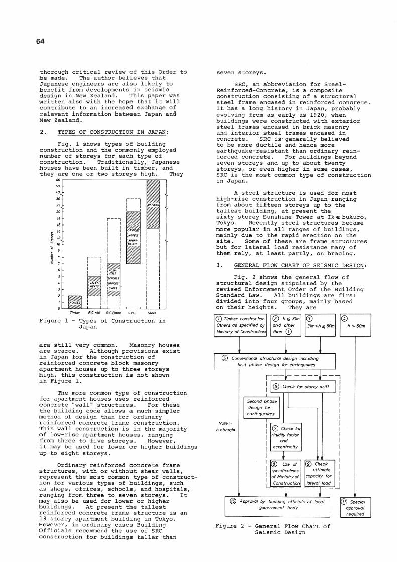
Fig. 1 shows types of building construction and the commonly employed number of storeys for each type of construction. Traditionally, Japanese houses have been built in timber, and they are one or two storeys high. They
60
R.C.Wail R.C.Fmme
Figure 1 - Types of Construction in Japan
are still very common. Masonry houses are scarce. Although provisions exist in Japan for the construction of reinforced concrete block masonry apartment houses up to three storeys high, this construction is not shown in Figure 1.
The more common type of construction for apartment houses uses reinforced concrete "wall" structures. For these the building code allows a much simpler method of design than for ordinary reinforced concrete frame construetion. This wall construction is in the majority of low-rise apartment houses, ranging from three to five storeys. However, it may be used for lower or higher buildings up to eight storeys.
Ordinary reinforced concrete frame structures, with or without shear walls, represent the most common type of construction for various types of buildings, such as shops, offices, schools, and hospitals, ranging from three to seven storeys. It may also be used for lower or.higher buildings. At present the tallest reinforced concrete frame structure is an 18 storey apartment building in Tokyo. However, in ordinary cases Building Officials recommend the use of SRC construction for buildings taller than
seven storeys.
SRC, an abbreviation for Steel-Reinforced-Concrete, is a composite construction consisting of a structural steel frame encased in reinforced concrete. It has a long history in Japan, probably evolving from as early as 1920, when buildings were constructed with exterior steel frames encased in brick masonry and interior steel frames encased in concrete. SRC is- generally believed to be more ductile and hence more earthquake-resistant than ordinary reinforced concrete. For buildings beyond seven storeys and up to about twenty storeys, or even higher in some cases, SRC is the most common type of construction in Japan.
A steel structure is used for most high-rise construction in Japan ranging from about fifteen storeys up to the tallest building, at present the sixty storey Sunshine Tower at Ik e bukuro, Tokyo. Recently steel structures became more popular in all ranges of buildings, mainly due to the rapid erection on the site. Some of these are frame structures but for lateral load resistance many of them rely, at least partly, on bracing.
3. GENERAL FLOW CHART OF SEISMIC DESIGN:
Fig. 2 shows the general flow of structural design stipulated by the revised Enforcement Order of the Building Standard Law. All buildings are first divided into four groups, mainly based on their heights. They are
(J) Timber construction Others, as specified by Ministry of Construction
(D hg 31m and other than ®
® 31m <h ^ 60m
© h > 60m
(s) Conventional structural design including first phase design for earthquakes
Note h~ height
@ Check for storey drift
Second phase design for
earthquakes
@ Check for rigidity factor
and eccentricity
® Use of specifications of Ministry of Construction
(9) Check ultimate
capacity for lateral load
@ Approval by building officials of local government body
@ Special approval required
Figure 2 - General Flow Chart of Seismic Design

65
shown in the boxes marked as (1), (2), (3) and (4).
For buildings taller than 60 m (box 4)) provisions of the Building Standard Law do not apply directly. These high-rise buildings are to be designed by the "special study", usually incorporating time-history non-linear response analyses. The design is then subjected to the technical review by the Highrise Building Structure Review Committee of the Building Center of Japan. Upon its recommendation, a special approval of the structural design is issued by the Ministry of Construction.
For buildings, not exceeding 60 m in height, the basic intent of the general flow in Fig. 2 is to make a two-phase design. This means that an additional design phase, hereafter called the second phase design for earthquakes, follows the conventional structural design, including the traditional seismic design, hereafter called the first phase design for earthquakes . The first phase design is for strong earthquakes which can occur several times during the life time of the building. The second phase design is intended mainly for severe or extraordinary earthquakes which could occur once in the life time of the building.
The application of the two-phase design is shown in Fig. 2, for three different groups of buildings up to 60 m in height, in boxes (1), (2) and (3). For all of these buildings, conventional structural design is carried out first, box (5), including the first phase seismic design. As explained later, this is an allowable stress design for permanent and temporary loadings, also taking ultimate strength into account. Major changes in the code relevent to this phase of the design is the method of seismic force evaluation.
Box (1) is for buildings of the most prevalent construction type in Japan. A detailed description of these buildings is given later. They include low-rise buildings of reinforced concrete with a generous amount of shear walls. For these buildings there is ample experience in Japan in seismic design and also evidence of seismic behaviour. The first phase design, basically unchanged from the rules of the former building cose, should be successful in providing sufficient seismic resistance for these buildings to withstand severe earthquakes. Hence the second phase design need not be applied to these buildings.
For buildings of boxes (2) and (3), the second phase design follows. The most important step in the second phase design is the evaluation of ultimate capacity for lateral load in box (9) . However, other considerations, listed in boxes (6), (7) and (8), are also included in the second phase design.
The evaluation of storey drift, box(6), is intended to eliminate flexible structures which might experience excessively large lateral deflection under the seismic
loading. In the case of ordinary reinforced concrete buildings this check will never be critical. However, the results of calculations are needed later for items given in box (7) or (9).
For buildings whose height is up to 31 m, box (2), there is a choice of flow into boxes (7) and (8), or into box (9). Box (7) requires a check for the rigidity factor and the eccentricity. The rigidity factor refers to the vertical distribution of lateral stiffness. The purpose of this check is to eliminate buildings with one or more flexible storeys among the other storeys, such as the soft first storey. Checking for eccentricity is necessary to provide protection against excessive torsional deformation. These checks are followed by satisfying a set of additional minimum requirements sepcified by the Ministry of Construction, Box (8), to ensure certain levels of strength and ductility. Thus, the option of boxes (7) and (8) is intended to allow exemption from the evaluation of the ultimate capacity for lateral load for buildings up to 31 m in height, if they have a reasonably regular structural system conforming with the additional minimum requirements.
However, there is no such choice for buildings exceeding 31 m in height, box (3). These must be evaluated and checked for the ultimate lateral load carrying capacity. This route is the most straightforward application of the philosophy of the two-phase design.
The purpose of the check for ultimate capacity for lateral load is to evaluate the actual strength of the structure by means of limit analysis, and to ascertain that the response deformations would indeed lie within the ductility capacity provided.
The structural design and drawings must be presented to the local government body for approval by the Building Official of the city, town, or prefecture, as conforming to the requirements of the Building Standard Law.
4. FIRST PHASE DESIGN FOR EARTHQUAKES:
4.1 Load Combinations and Design Method -
The first phase design for earthquakes, as shown in box (5) of Fig. 2, is a part of conventional structural design as prescribed by the Enforcement Order of the Building Standard Law, which considers in usual circumstances five kinds of loading. These are : dead load, D, live Load, L, snow load, S, wind forces, W, and seismic forces, E• For permanent loading, the following load combinations are to be considered:
F = D + L (1)
F = D + L + S (in designated snowy areas)(la)
For short time (temporary) loading, the following load combinations are to be considered:
F = D + L 4- S (2)
66
D + L + W (3) 4.3 The Seismic Zone Factor -
F = D + L + S + W
(in designated snowy areas) (3a)
F = D + L + E (4)
F = D + L + S + E (in designated snowy areas) (4a)
In the case of reinforced concrete buildings, Eqs. (2) (3) or (3a) will never be critical because of the dominance of dead load, hence only Eqs. (1) and (4), or Eqs (2a) and (4a) , are used.
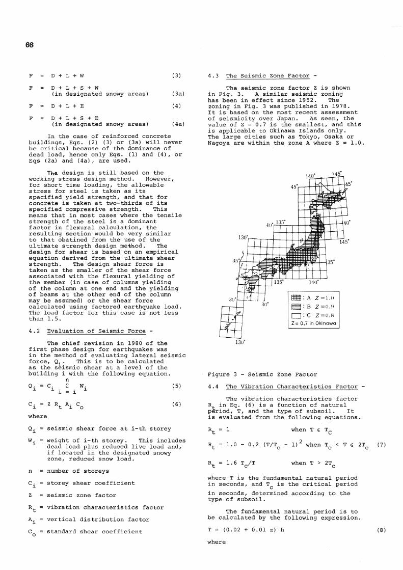
The seismic zone factor Z is shown in Fig. 3. A similar seismic zoning has been in effect since 1952. The zoning in Fig. 3 was published in 1978. It is based on the most recent assessment of seismicity over Japan. As seen, the value of Z = 0.7 is the smallest, and this is applicable to Okinawa Islands only. The large cities such as Tokyo, Osaka or Nagoya are within the zone A where Z = 1.0,
The design is still based on the working stress design method. However, for short time loading, the allowable stress for steel is taken as its specified yield strength, and that for concrete is taken at two-thirds of its specified compressive strength. This means that in most cases where the tensile strength of the steel is a dominant factor in flexural calculation, the resulting section would be very similar to that obatined from the use of the ultimate strength design method. The design for shear is based on an empirical equation derived from the ultimate shear strength. The design shear force is taken as the smaller of the shear force associated with the flexural yielding of the member (in case of columns yielding of the column at one end and the yielding of beams at the other end of the column may be assumed) or the shear force calculated using factored earthquake load. The load factor for this case is not less than 1.5.
4.2 Evaluation of Seismic Force -
The chief revision in 1980 of the first phase design for earthquakes was in the method of evaluating lateral seismic force, . This is to be calculated as the seismic shear at a level of the building i with the following equation.
n Q i
C i
W i
Z R. A. C t l o
(5)
(6)
where
Z =
R t =
A i = c =
seismic shear force at i-th storey
weight of i-th storey. This includes dead load plus reduced live load and, if located in the designated snowy zone, reduced snow load.
number of storeys
storey shear coefficient
seismic zone factor
vibration characteristics factor
vertical distribution factor
standard shear coefficient
: A z =i.(j HI: B z=o.9 I |: C Z=o.8 Z - 0.7 in Okinawa
130°
Figure 3 - Seismic Zone Factor
4.4 The Vibration Characteristics Factor -
The vibration characteristics factor R t in Eq. (6) is a function of natural period, T, and the type of subsoil. It is evaluated from the following equations.
when T ^ T_
1.0 0.2 (T/T - 1 ) * when T < T £ 2T c c c
(7)
1.6 T c/T when T > 2T
where T is the fundamental natural period in seconds, and T^ is the critical period in seconds, determined according to the type of subsoil.
The fundamental natural period is to be calculated by the following expression.
T = (0.02 + 0.01 a) h (8)
where

67
h = height of the building in metres
a = ratio of the height of storeys, consisting of steel columns and girders, to the entire height h
TABLE 1 - VALUES OF T
This means that T = structures and T = structures.
0.03 h for steel 0.02 h for concrete
Type JZT Soil {very soft)
Type S Soil (soft)
Type I Soil (hard)
0 tO 2.0
Natural Period (sec)
Figure 4 - Vibration Characteristics Factor R,
The critical period T is given in Table 1. The resultin§ value of R t is shown in Fig. 4.
When the period of vibration is more accurately evaluated by a suitable method, or the vibration characteristics coefficient is evaluated by a special study considering structural behaviour during earthquakes, such as soil-structure interaction, the value of R̂_ may be taken less than the value given by Eqs. (7) and (8), but not less than 3/4 of the value given by these equations.
4.5 Vertical Distribution Factor -
The vertical distribution factor A. in Eq. (6) specifies the distribution or lateral seismic forces, and is to be calculated by the following expression
A. = 1 + {- -a.) 2T 1 + 3T (9)
where = non dimensional weight (or height)
by the following expression n Z W.
(10) n Z W.
i = 1 1
Type of Soil
Type I
Type II
Type III
Description of Soil
Rock, stiff sand or gravel, and other soils mainly consisting of tertiary or older layers or any other soil that is shown by a special study to possess a natural period similar to above soils
0.4
Other than type I or Type III
3.6
Alluvium mainly consisting of organic or other soft soil (including fill if any) whose depth is 30 m or greater^ reclaimed land from swamps or muddy shoal 0.8 where the ground depth is 3 m or greater and less than 30 years have passed since the reclamation, or any other soil that is shown by special study to possess a natural period similar to above soils
0 1 2 3 4 5 6 7 8
' V&/ ' 1+3T
K 0 L-
where = weight of i-th storey
n = number of storeys Figure 5 - The vertical Distribution
Factor A. x

68
As seen in Fig. 5, the vertical distribution factor is close to a uniform value for shorter periods. Larger portion of lateral force is to be assigned to the top of the building in long period structures.
Fig. 6 shows values of the vertical distribution factor A. (Fig. 6a) and associated lateral fo£ce dis tribution for special cases of structures with uniform mass per storey and identical storey heights of 3.6 m. A^ in the lowest storey is always 1.0. The value of A^ in the uppermost storey increases as the number of storeys increases. The terms and T in Eq. (9) can be easily determined for these structures. Fig. 6b shows the distribution of floor forces for a- given value of total base shear. This was simply obtained from computing the differences of storey shear forces determined with the vertical distribution factors, A^, given in Fig. 6a. The distribution of forces with height may be compared with the linear variation which would be used for the identical structure in New Zealand.
When the vertical distribution of seismic force is evaluated by a special study considering the dynamic characteristics such as spectral modal analysis, Eqs. (9) and (10) need not be used.
4.6 Standard Shear Coefficient -
The standard shear coefficient C o
in Eq. (6) has been determined to be not less than 0.2 for the first phase seismic design. An exception is the case of wooden buildings in designated soft subsoil areas, when the value of C Q
must be not less than 0.3. Eq. (6) will also be used later for ultimate capacity for lateral load in the second phase seismic design, in which case the value of the standard shear coefficient C must be not less than 1.0. o
In the commentary of the revised Building Standard L a w ^ ) f it is explicitly stated that the adopted two-phase design procedure for earthquakes can be regarded as the design for two different intensities of earthquake motion. The first phase design, with the adoption of C Q = 0.2, is essentially the same as prescribed by the previous Buildings Standard Law. The adoption of seismic coefficient of this level originated from the experience of 1923 Kanto earthquake in Tokyo.
After the enforcement of the seismic design in 1924, practically all Japanese buildings have been designed to the level of protection corresponding to the design seismic coefficient C Q = 0.2. Experiences with earthquakes of JMA intensity IV and V have shown that the majority of these buildings have behaved satisfactorily, and were almost without damage. The purpose of the first phase
0 0.5 1.0 1.5 2.0 2.5
Vertical distribution factor, Aj
0 I ' " _ l I : 1 0 0.5 10 1.5 2.0 2.5
Floor force distribution factor
Figure 6 - The vertical (A^) and Floor Force Distribution Factors
design is now to protect buildings in case of earthquakes which can occur several times during the life of the building. Such earthquake motions may be considered as having an intensity V on the Japanese Meteorological Agency (JMA) intensity scale, with the maximum acceleration of 80 to 100 gal (1 gal = 1 cm/sec 2). Buildings are expected to respond to earthquakes of this level without loss

69
of function. This design objective is assumed to be achieved by the adoption of the traditional level of seismic force and the traditional method of allowable stress design.
As stated earlier the newly added second phase design is intended to ensure safety against an earthquake which could occur once in the life time of the building. Such earthquake motion may be as strong as that of 19J23 Kan to earthquake in Tokyo, of VI br VII in terms of JMA intensity scale, with the maximum acceleration of 3 0 0 to 4 0 0 gal ( 0 . 3 to 0 * 4 g ) . The traditional seismic design, as prescribed by the previous Enforcement Order, did not include direct evaluation of safety against such earthquake motions. It was expected that buildings designed for the design seismic coefficient of C = 0 . 2 would safely survive severe earthquakes as a result of built-in overstrength and ductility. Whether the structure possessed adequate levels of overstrength and sufficient ductility was not expressly required to be confirmed.
Recent experiences in major earthquakes, such as 1 9 6 8 Tokachi-oki earthquake or* the 1 9 7 8 Miyagiken-oki earthquake, have shown in fact that the majority of Japanese buildings had adequate overstrength and ductility to survive without any damage or with minor ^ damage. However, about 1 0 percent of the affected buildings suffered appreciable damage, and several buildings among these reached the stage of collapse. The newly introduced second phase design procedure is intended to ensure that serious damage will not occur, and this will be discussed later.
4 . 7 Seismic Force Acting in the Basement -
The revised Building Standard Law also contains provisions for the seismic force to be considered at basements. This is a new requirement. Unlike the seismic shear force for the upper portion of buildings, the seismic force in the basement is to be calculated as the inertia force acting at the basement of the building directly, by multiplying the sum of the total dead and live loads for the basement, W , by the following seismic coefficient.
k * 0 . 1 ( 1 - | Q ) Z ( 1 1 )
where
k = horizontal seismic coefficient
H = depth from the ground level in m measured to the bottom of the basement, but it -sKall not be taken more than 2 0 m
Z = seismic zone factor as in Eq. ( 6 )
The storey shear force Q g at any basement level may then be calculated as follows.
Q = Q' + k W n ( 1 2 )
where
Q 1 .= the portion of seismic storey shear force in the adjacent upper storey that is carried by columns and shear walls directly above the basement being considered
W B = weight of the basement storey being considered
Fig. 7 shows the distribution of seismic coefficient by Eq. ( 1 1 ) .
Ground level
0.05Z
Figure 7 - Seismic Coefficient for Basements
5. SECOND PHASE DESIGN FOR EARTHQUAKES:
5.1 Outline of the Second Phase Design -
As was discussed earlier, the two-phase design procedure in the revised Building Standard Law can be regarded as design for two different intensities of earthquake motion. In particular, the second phase design was introduced as the direct and explicit evaluation of overstrength and ductility. This identifies whether the available ductility capacity is sufficient for the ductility demand in case of severe earthquake motions of the class of JMA intensity scale of VI or VII, considering also the overstrength of the structure provided. Such evaluation can be made only when the object is clearly defined. Structural configuration and dimension of members and in some cases even the detailing, must be given. In this sense the second phase design may be regarded as analysis, rather than design. The principal objective of the first phase design may be said to create the object for this analytical procedure.
Thus the essential part of the second phase design is a check for ultimate lateral load carrying capacity, (box 9 ) in Fig. 2 ) . However, it has been pointed out that several other checks are necessary as indicated by experience gained in recent earthquakes in Japan. They are thus included in the second phase design. See boxes ( 6 ) , ( 7 ) and ( 8 ) in Fig. 2 .

70
5.2 Storey Drift -
The storey drift limitation, introduced into the Building Standard Law for the first time, is to be investigated first, as shown by the box (6) in Fig. 2. The storey drift 6^ under the action of design seismic shear force of Eq. (5) is calculated by the elastic analysis, and storey deformation angle is calculated as
R. = 6./n. (13)
R. where h^ is the storey height. should be not greater than 1/200. If nonstructural elements are used that can sustain greater structural deformation, or if they are made of deformable materials , R. can exceed the above limit. However "J" in no case should R. exceed 1/120.
and (8).
The rigidity factor is defined in Fig. 8. The reciprocal of the storey deformation angle R^ is expressed by r s^, and then the rigidity factor of the i-th storey R g^ is defined as the ratio of r . and the si
<4 TTTTTT] fTTTT II II 1
jj|jf|||||f| l l l l l l l l l l l l
F m
G.L 77777777? in.
:^rs3'Rs3=rs3/rso
'R2 = 1/rs2-Rs2= rs2/rsa
r Rf = 1/rs1,Rs1 = r s 1 / r S Q
/"sa- ( rsi +rs2+rs3+rS4)
This storey drift limitation was introduced in view of increasing earthquake damage to architectural parts of buildings, particularly in steel buildings. It should be noted that the calculated storey drift results from the action of seismic shear force given by Eq. (5), i.e. for the first phase design for earthquakes. Under the action of severe earthquakes assumed in the second phase design, the storey drift will become much larger than that predicted by Eq.(13) .
For reinforced concrete buildings the storey drift limitation will be seldom critical because of the large initial stiffness of the structure. Nevertheless this check cannot be omitted as the results are used in the subsequent steps of second phase design.
5.3 Rigidity Factor and Eccentricity Factor -
One of the most effective ways in the design of earthquake-resistant buildings is to provide a well-balanced, regular structural lay-out for the building in the early stage of the design. Buildings with non-uniform rigidity in the vertical direction, for example having a soft first storey, or buildings with horizontal eccentricities, for example having an eccentric service core, should be designed with particular care. They are certainly more difficult to design than regularly shaped buildings. As a result of these requirements the structure is likely to become more costly and yet the benefits in terms of behaviour remain doubtful. Whenever possible, such irregular buildings should be avoided. Recently observed damage after the 1968 Tokachi-oki earthquake or the 1978 Mayagiken-oki earthquake revealed in particular the vulnerability of irregular buildings and indicated the superior performance of regular buildings.
Consequently, it was intended to provide some relaxation in the design of regular buildings in the flow chart of Fig. 2. For buildings whose height does not exceed 31 m, (box (2)) it was made possible to bypass box (9), by ensuring the requirements of boxes (7)
Figure 8 - Rigidity Factor
average value i.e.
si where r . = si
and
r = sa
r . /r si sa (14)
1/R,
n Z r ./n
si /
R g^ is less than 1.0 in a storey whose rigidity is less than the average rigidity of storeys. The Building Standard Law now requires that
> 0.6 (15)
for any storeys. If there is a storey which does not satisfy Eq. (15), the structure has to be checked for ultimate lateral load carrying capacity, i.e. it must follow the flow into box (9) in Fig. 2.
Figure 9 - Principal Quantities to Determine Storey Stiffness Properties
The definition of eccentricity factor is as shown in Fig. 9. G is the centre of gravity of the total mass above the storey being considered. R is the centre of rigidity, or centre of rotation under the action of torsional moment. Eccentricity distances associated

71
with loadings in x and y- direction, e x
and e^, respectively, are measured from R as shown. Then the eccentricity factors R , R are defined as follows. ex ey
(16a) e /r x' ex
ey e /r y ey (16b)
where
r , r = elastic radii defined as follows ex ey
r e x /• rotational stiffness translational stiffness in x direction
ey rotational stiffness translational stiffness in y direction
(17a)
(17b)
The terms rotational and translational stiffness will be defined subsequently.
Rex * and
R $ ey
The Building Standard Lay specifies
0.15
0.15
in all storeys. If there is any storey which does not satisfy Eq. (17), the building has to be checked for the ultimate lateral load carrying capacity.
To illustrate the application in the following, a numerical example of a three-storey reinforced concrete building shown in Fig. 10 is used. This building is one of the design examples given by Umemura et al when illustrating the application of dynamic design for earthquakes (5) The building has several shear walls. Its lateral stiffness is so high that it can almost be treated as a box. However, it is used here only to show the numerical procedure involved. Fig. 10 shows the lateral stiffness of each vertical member in two directions. Values of stiffness were arbitrarily reduced from those originally given( 5), into a range of values more commonly found in reinforced concrete buildings.
Table 2 summarizes the seismic force caluclation based on Eqs. (5), (6), (7), (8), (9) and (10). The seismic zone factor Z is assumed to be 1.0, and from the period T = 0.223 seconds found from Eq. (8), the vibration characteristics factor R = 1.0 regardless of the type of soil. The standard shear coefficient is c
0 = 0-2. After finding the storey shears Qjy seismic forces on each mass, F^, are found from the difference of Q..
l Table 3 shows the calculation of
rigidity factors using Eq. (14). Total stiffness Z K. in each direction is given
in Fig. 10. The stiffness K i for each element in each storey should strictly be determined with a trial and error process using an arbitrary but sensible load pattern which results in identical storey deflections for all elements at all floors. Clearly this is a complicated process and for this reason a suitable first order approximation is generally used because the storey drift does not need to be determined with great accuracy. The storey drift is divided by storey height to obtain storey deformation angle R.. These are found to be much smaller than i the limiting value of 1/200 in this case. The rigidity factor R g i by Eq. (14) is the smallest in the second storey in both directions, but larger than the limiting value of 0.60.
Table 4 shows the computations for the eccentricities. From the lateral stiffness plotted on the plans of Fig. 10, location of the centre of rigidity R is found by
1
I K £ (K x)
y Z K
where in this example the distance x and y are measured from the lower left corner of the plan and shown in Fig. 9. The locaiion of the centre of rigidity R may be seen in Fig. 10. The centre of gravity G is assumed to be located at the geometrical centre of the plan.
To find the eccentricity factor from Eq. (16), elastic radius is calculated. In Table 4, row (6) lists the second moment of stiffness in each direction with respect to the chosen reference point Gl on the plan, and the row (7) shows the second moment of stiffness with respect to the centre of rigidity, R. These are obtained from first principles i.e.
I = Z (K x y 2) - (I K x) y 2
I = I (K x 2) - (Z K ) x 2
y y y The rotational stiffness is taken as the sum of I x and I . Hence the elastic radii are found in row (10) as follows. The calculated eccentricity factor from Eq. (16) is larger in the x direction but in all storeys the limitation of R e x £ 0.15 is satisfied.
5.4 Specified Minimum Requirements -
A building which passed the checks for the rigidity and eccentricity factors is considered to be a reasonably regular building. It is likely to be seismically safe. Hence they can be exempted of the time consuming check for ultimate lateral load carrying capacity if they can also satisfy a set of minimum requirements specified by the Ministry of Construction.
As to such a set of minimum requirements it appears that experience of the future is

72
1st Storey 2nd Storey 3rd Storey
NOTE :- Distances are in metres Lateral stiffness of members is in kN/mm units.
Figure 10 - Floor Plans and Stiffnesses of 3 Storey Example Structure
TABLE 2 - EXAMPLE OF SEISMIC FORCE CALCULATION:
(1) Storey
i First
1 Second
2 Third
3
(2) Storey height h ± (m)
4.15 3.50 3.50
(3) Storey weight W ± (kN) 3276 2929 3046
(4) 3 S W. (kN)
i = i 1 9251 5975 3046
(5) a i 1.000 0.646 0.329
(6) l//a7 - 0.000 0.598 1.414
(7) A i 1.000 1.160 1.378
(8) c ± 0.200 0.236 0.276
(9) Storey shear Q ± (kN)
1850 1410 841
(10) Seismic force F ± (kN)
440 569 841
Note: (7) Total height h = Z h. = 11.15 m Period T = O.oi h = 0.223 sees
2T/(1 + 3T) = 0.267 (8) Z = 1.0 (assumed)
R = 1.0 (from the period above)

73
TABLE 3 - EXAMPLE OF STIFFNESS RATIO CALCULATION:
(1) Direction Transverse X Longitudinal y
(2) Storey i
1 2 3 1 2 3
(3) Stiffness K ± (kN/mm)
595.3 264.1 165.8 322.7 199.7 175.0
(4) Storey shear Q i (kN)
1850 1410 841 1850 1410 841
(5) Storey drift <5̂ (mm) 3.11 5.34 5.07 5.73 7.06 4.81
(6) Storey height h. (mm) l 4150 3500 3500 4150 3500 3500
(7) Deformation angle
1 /1334 ^ 6 5 5 1 / 6 9 0 ^ 7 2 4 ^ 4 6 9 l y /728
(8) r s i 1334 655 690 7 24 496 728
(9) rsa 893 649
(10) Stiffness ratio R • sx
1.49 0.73 0.77 1.12 0.76 1.12
Note: (3) From Fig. 10 (4) From Table 2 (7) For all R., R. < l / 2 0 0
(10) For all R ., R . > 0.60 si si
TABLE 4 - EXAMPLE OF ECCENTRICITY CALCULATIONS:
(1) Storey i
Fi rst 1
Second 2
rhird 3
(2) Direction X y X y X y
(3) Stiffness ZK EK x y (kN/mm)
595.3 322.7 264.1 199.7 165.8 175.0
(4) Z(K xy) Z(K yx) (kNm/mm)
4840 1701 2017 1134 1260 994
(5) y x(m) 8.13 5.27 7.64 5.68 7.60 5.68 (6) Z(K xy 2) ZK yx 2)
(kNm 2/mm) 64590 15400 33130 11840 20750 10540
(7) I I x y . (kNm 2/mm)
25240 6440 17710 5400 11170 4890
(8) I + I x y (kNmVmm) 31680 23110 16060
(9) e e (m) x y
0.87 0.63 1.36 0.22 1.40 0.22
(10) r r (m) ex ey 7. 29 9.91 9.35 10.76 9.84 9.58
(11) Eccentricity Ratio R R
ex ey 0.119 0.064 0.145 0.020 0.142 0.023
Note: (4) - (10) x, y are measured from lower left corner (Point Gl) of the plan, in m. I and I have dimensions of (kN/mm) m 2 , thus r and r are in m. x y _ _ e x e Y (9) e = 18.0/2 - y, e x r = 11.8/2 - x
y (11) For all R and R , R < 0.15 ex ey' ex,y r
r e x y x y

74
still required. Therefore the following requirements have necessarily a temporary character.
For steel structures not exceeding 31 m in height, the following conditions must be satisfied in the structural calculations,
(1) If the building includes storeys (except the basement) that are braced to carry horizontal forces, the force in the members in each of those storeys due to the design seismic force must be increased by the factor B as follows
when 3 $ 5/7
3 > 5/7
B = 1 + 0 • 7
B = 1.5
where "3 is the ratio of horizontal force carried by the braces to the entire storey shear in the storey being considered.
(2) It must be shown, when necessary, that columns, girders, and their connections, do not lose their load-carrying capacity rapidly due to local buckling or fracture.
Thus for steel structures the minimum requirements result in assurance of increased strength and ductile behaviour of braces, and ductile behaviour of frames when the frames carry some portion of lateral loads.
For reinforced concrete and steel reinforced concrete structures not exceeding 31 m in height, the minimum requirements consist of satisfying any one of the following three conditions.
(1) In each storey the following empirical equations must be satisfied.
For RC Z 2.5 A + Z 0.7 A > 0.75 Z W A. w c ' 1
(18a.) For SRC Z 2.5 A + Z 1.0 A * w c 0.75 Z W A i
(18b)
where
horizontal area of shear walls in the direction of the seismic forces that are being considered in mm2
A = horizontal area of columns in mm c
Z =
W =
A.
seismic zone factor given in Eq.(6)
weight of the portion of the building that is carried by the storey being considered in N
vertical distribution factor as in Eq. (6)
This expression is similar to the one used in specifying buildings for which second phase design for earthquakes is not
required (box (1) in Fig. 2 ) . This aspect will be discussed later in more detail, but in essence Eq. (18) specifies the condition for buildings with relatively large amount of shear wall area and hence with a relatively high ultimate lateral load carrying capacity.
(2) In each storey the following empirical equations must be satisfied:
For RC Z 1.8 A w + Z 1.8A c £ Z W A ±
For SRC Z
(19a)
1.8 A = Z 2.0A > Z W A. w c ' 1 (19b)
where A^, Eq. (18).
Z, W, A. are as defined for x
This expression will also be reexamined in connection with the conditions for which second phase design for earthquakes is not required. Eq. (19) intends to distinguish buildings with many columns with wing walls and hence with relatively high ultimate lateral load carrying capacity and with reasonable ductility. Columns with wing walls are extensively used in Japan. Typical columns with relatively small wing walls are those situated on grid points El and E3 in Fig. 10. The wing walls significantly contribute to the strength and stiffness for earthquake actions in the y direction.
(3) All columns and girders must be designed so that premature shear
failure is prevented. This is to ensure energy dissipating capacity for the frames. No requirements are made for the amount and behaviour of shear walls.
5.5 Check for Ultimate Lateral Load Carrying Capacity -
The most important step in the second phase design for earthquakes is the check for ultimate lateral load carrying capacity, i.e. box (9) in Fig. 2. First, member strengths are evaluated, based on the material strength and geometry of sections obtained from the results of the first phase design. Then the ultimate lateral load carrying capacity is calculated by any method, including incremental nonlinear analysis, limit analysis, and simplified methods suitable for approximate hand calculation. In any case, an appropriate vertical distribution of horizontal forces is assumed, and the storey shear in each storey, associated with the formation of collapse mechanism, is found.
It is required that the ultimate lateral load carrying capacity in each storey thus found must exceed the shear force Q given below
Q = D F Q , un s es ud
where
(20)
= seismic shear in a storey
75
D = s t r u c t u r a l c h a r a c t e r i s t i c s f a c t o r s
F = a s h a p e f a c t o r w h i c h c o n s i d e r s t h e e s r i g i d i t y a n d t h e e c c e n t r i c i t y f a c t o r s
T h e t o t a l s e i s m i c s h e a r i n t h e s t o r e y , Q T i s c a l c u l a t e d
u s i n g E q s . ( 5 ) a n d ( 6 ) . Thus t h i s p r o c e d u r e i s s i m i l a r t o t h e e v a l u a t i o n o f s e i s m i c f o r c e i n t h e f i r s t p h a s e d e s i g n f o r e a r t h q u a k e s , e x c e p t t h a t t h e s t a n d a r d s h e a r c o e f f i c i e n t C i n E q . ( 6 ) i s now t a k e n t o b e n o t l e s s t h a n 1 . 0 . T h e r e f o r e Q d i s f i v e t i m e s t h e d e s i g n s t o r e y s h e a r o B t a i n e d i n t h e f i r s t p h a s e d e s i g n , u n l e s s t h e d y n a m i c c h a r a c t e r i s t i c s o f t h e b u i l d i n g , s u c h as t h e n a t u r a l p e r i o d , v i b r a t i o n c h a r a c t e r i s t i c s f a c t o r R , o r t h e v e r t i c a l d i s t r i b u t i o n f a c t o r A ^ , a r e r e c o m p u t e d .
T h e f a c t o r s D a n d F „ a r e e x a m i n e d i n s e s t h e f o l l o w i n g t w o s e c t i o n s r e s p e c t i v e l y .
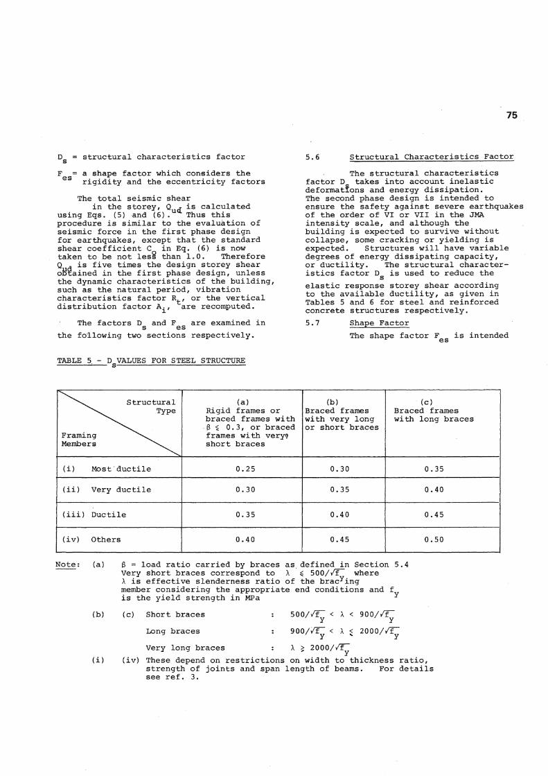
5 . 6 S t r u c t u r a l C h a r a c t e r i s t i c s F a c t o r
T h e s t r u c t u r a l c h a r a c t e r i s t i c s f a c t o r D t a k e s i n t o a c c o u n t i n e l a s t i c d e f o r m a t i o n s a n d e n e r g y d i s s i p a t i o n . The s e c o n d p h a s e d e s i g n i s i n t e n d e d t o e n s u r e t h e s a f e t y a g a i n s t s e v e r e e a r t h q u a k e s o f t h e o r d e r o f V I o r V I I i n t h e JMA i n t e n s i t y s c a l e , a n d a l t h o u g h t h e b u i l d i n g i s e x p e c t e d t o s u r v i v e w i t h o u t c o l l a p s e , some c r a c k i n g o r y i e l d i n g i s e x p e c t e d . S t r u c t u r e s w i l l h a v e v a r i a b l e d e g r e e s o f e n e r g y d i s s i p a t i n g c a p a c i t y , o r d u c t i l i t y . T h e s t r u c t u r a l c h a r a c t e r i s t i c s f a c t o r D i s u s e d t o r e d u c e t h e
s e l a s t i c r e s p o n s e s t o r e y s h e a r a c c o r d i n g t o t h e a v a i l a b l e d u c t i l i t y , as g i v e n i n T a b l e s 5 a n d 6 f o r s t e e l a n d r e i n f o r c e d c o n c r e t e s t r u c t u r e s r e s p e c t i v e l y . 5 * 7 S h a p e F a c t o r
T h e s h a p e f a c t o r F i s i n t e n d e d
TABLE 5 - D VALUES FOR STEEL STRUCTURE
S t r u c t u r a l T y p e
F r a m i n g Members
( a ) R i g i d f r a m e s o r b r a c e d f r a m e s w i t h
• 3 ^ 0 . 3 , o r b r a c e d f r a m e s w i t h v e r y 9 s h o r t b r a c e s
( b ) B r a c e d f r a m e s w i t h v e r y l o n g o r s h o r t b r a c e s
( c ) B r a c e d f r a m e s w i t h l o n g b r a c e s
( i ) M o s t d u c t i l e 0 . 2 5 0 . 3 0 0 . 3 5
( i i ) V e r y d u c t i l e 0 . 3 0 0 . 3 5 0 . 4 0
( i i i ) D u c t i l e 0 . 3 5 0 . 4 0 0 . 4 5
( i v ) O t h e r s 0 . 4 0 0 . 4 5 0 . 5 0
N o t e : ( a )
( b )
( i )
3 = l o a d r a t i o c a r r i e d b y b r a c e s a s d e f i n e d i n S e c t i o n 5 . V e r y s h o r t b r a c e s c o r r e s p o n d to X $ 5 0 0 / / F " w h e r e X i s e f f e c t i v e s l e n d e r n e s s r a t i o o f t h e b r a c k i n g member c o n s i d e r i n g t h e a p p r o p r i a t e e n d c o n d i t i o n s a n d f i s t h e y i e l d s t r e n g t h i n MPa ^
< 2 0 0 0//1T
( c ) S h o r t b r a c e s
L o n g b r a c e s
V e r y l o n g b r a c e s
( i v ) T h e s e d e p e n d o n r e s t r i c t i o n s o n w i d t h t o t h i c k n e s s r a t i o , s t r e n g t h o f j o i n t s a n d s p a n l e n g t h o f b e a m s . F o r d e t a i l s s e e r e f . 3 .
5 0 0 / / f y < X < 9 0 0 / / f y
9 0 0 / / F ; <
X > 2 0 0 0 / / F ;

76
TABLE 6 - D VALUES FOR REINFORCED CONCRETE STRUCTURES s (For steel reinforced concrete structures, subtract 0.05 from the tabulated value of D g)
Structural Type
Framing Members
(a) Rigid frame, or very ductile shear wall with 3 < 0.5 w^
(b) Very ductile or ductile shear wall with
(c) Very ductile or ductile shear wall with 3 W > 0.7, or less ductile shear wall
(i) Most ductile 0.30 0.35 0.40
(ii) Very ductile 0.35 0.40 0.45
(iii) Ductile 0.40 0.45 0.50
(iv) Others 0.45 0.50 0.55
Note: (a)~(c) 3 = Ratio of load carried by shear walls to total storey shear. The classification, very duetile, ductile, or less ductile shear walls depends mainly on the shear stress level at ultimate and on the mode of failure. For details see Ref. 3.
(i)~(iv) These depend on restrictions on length-to-depth ratio, axial force, axial reinforcement ratio, shear stress level at ultimate state, and the mode of failure. For details see Ref. 3.
to take into account the irregularity of the structure expressed in terms of rigidity factor and eccentricity. It is determined as follows:
where
s and where
F
F F s e (21)
Basic shape factor determined as a function of the rigidity factor R (R . is given by s s i Eq. (14))
1.0 when R G £ 0.6
1 . 0 + § f | ( 0 . 6 -
0.3 < R < 0.6 s
R ) when s
= 1.5 when R < 0.3
(22a)
(22b)
(22c)
basic shape factor determined as a function of the eccentricity factor R (R or R are given e ex ey ^ by Eq. (16))
= 1.0 when R ^ 0.15 (23a)
1-° + STT5 ( R e 0.15 < R <
e
0.15) when
°- 3 (23b)
= 1.5 when R > 0.3 (23c)
The shape factor F e g is 1.0 for values of rigidity factor and eccentricity factor permitted in case of buildings up to 31 m in height for which there is an exemption for checking the ultimate lateral load carrying capacity. When irregularity causes these limits to be exceeded, the shape factor necessitates the provision of higher ultimate lateral load carrying capacity, or in cases when the ultimate lateral load carrying capacity cannot be increased, lower structural characteristics factor D must be used. Equations (22) and (23) s show that the value of the shape factor is limited to 1.5. However, this should be interpreted that such an extraordinar ily irregular structure cannot be handled by the shape factor concept. Any building with a storey having a rigidity factor R G less than 0.3, or eccentricity factor R greater than 0.3, should be redesign- e
ed for a better balance of mass and stiffness.
6. BUILDINGS FOR WHICH THE SECOND PHASE DESIGN IS NOT REQUIRED:
6.1 Specification of the Ministry of Construction ~
Box (1) in Fig. 2 refers to buildings most popular in Japan. With ample experience in earthquakes, they are judged to be safe without being subjected to the second phase design for earthquakes. Besides timber construction, they include the following, according to the specification of the Ministry of Construction(3) .

77
1. Masonry buildings with not more than three storeys, excluding the basement.
2. Reinforced concrete block masonry buildings with not more than three storeys, excluding the basement.
3. Steel buildings conforming to (a) through (f) below.
(a) Not more than three storeys, excluding the basement.
(b) Not more than 13 m in height, and not more than 9 m at eaves height.
(c) Horizontal distance between major vertical structural supports is not more than 6 m.
(d) Total floor area is not more than 500 m 2.
(e) Design seismic shear force in the first phase design is calculated with the standard shear coefficient taken not less than 0.3.
(f) End connections and joints of braces carrying components of horizontal earthquake forces must not fracture when the bracing member is yielding.
4. Reinforced concrete buildings, steel reinforced concrete buildings, or buildings consisting in part of reinforced concrete and in part of steel reinforced concrete, conforming to the requirements (a) and (b) below.
(a) Not more than 20 m in height.
(b) Horizontal area of shear walls and columns in each storey above ground shall satisfy the following equations.
For RC Z 2.5 A + E 0.7 A > Z W A. (24a) W C * X
For SRC Z 2.5 A + Z 1.0 A £ Z W A. (24b) W C X
where A = horizontal area of shear
walls in the direction of the seismic forces that are being considered in mm 2
A - horizontal area of columns in c o mm^
Z - seismic zone factor as in Eq. (6)
W = weight of the portion of the building that is carried by the storey being considered in N
A^ = vertical distribution factor as given by Eq. (6).
5. Buildings consisting of the mixture of two or more of the following constructions: timber, masonry, reinforced concrete block masonry and steel structures,
or buildings consisting of any one or more of these above construction types and .reinforced concrete or steel reinforced concrete construction, conforming to requirements (a) through (d) below.
(a) Not more than three storeys, excluding the basement.
(b) Not more than 13 m in height, and not more than 9 m at eaves height.
(c) Total floor area is not more than 500 m 2 .
(d) The storey consisting of steel construction must conform to requirements (c), (e) and (f) of Item 3 above.
(e) The storey consisting of reinforced concrete or steel reinforced concrete construction must conform to requirement (b) of Item 4 above.
6. Industrial (prefabricated) houses approved by the Ministry of Construction.
7. Other construction approved by the Ministry of Construction as having equivalent or larger safety against earthquakes as the items listed above.
6.2 Reinforced Concrete Buildings -
Among the structural types listed in Section 6.1, Item 4, defining reinforced concrete buildings that need not be subjected to the second phase design for earthquakes, is the most interesting and important from a technical point of view. The right hand side of Eq. (24) may be regarded as the storey shear due to 1 g response, or standard shear coefficient C Q = 1.0 and vibration characteristics factor R^ = 1.0. This would be the case for buxldings whose height is not more than 20 m. Hence Eq. (24) may be interpreted as a requirement that the lateral load carrying capacity, based on an average shear stress of 2.5 MPa for shear walls and 0.7 MPa for columns (1.0 MPa in case of SRC), should exceed the 1 g response storey shear.
The meaning of Eq. (24) may be explained with the aid of a "wall area index" vs "average shear stress" plot originated by Shiga. This relationship was already reported in New Zealand by Glogau(6) f with respect to the damage observed in the 1968 Tokachi-oki earthquake. Fig. 11 shows such a plot, also compiled by Shiga, with respect to damage observed in the 1978 Miyagiken-oki earthquake( 2).
The horizontal axis in Fig. 11 is wall area index, which is the ratio of the total wall area, Z A , in each
w' direction to the total floor area, Z A f , of the building. In the original literature this quantity is expressed in cm2/ra units, but here the percentage of the ratio is used instead. The vertical

78
axis of Fig. 11 records the average shear stress assuming 1 g response, where W is weight in N, and E A and E A were defined above. A nominal building wSight of 10 kPa per floor was assumed
hence
Z A + Z A w c 1-1.
0.7 •E A
E A x
(26)
2.5
•12.5Av/Z0.7Ac=0.75W
Ih8Aw*It8Ac= W -
x Failure Rank H and above
• Failure Rank I
and &efow 1 — r
12,5Aw-> WJAC = W
OS 10 15
14/
Figure 11 Wall Area Index and Average Shear Stress in Walls and Columns
in calculating the ordinates. This nominal building weight is a reasonable average of the actual weight of Japanese reinforced concrete buildings.
It was found from the plot for the 1968 Tokachi-oki earthquake( 6), that buildings which lie outside the rectangle bounded by wall area index E A^/E A^ = 0.003 and the average shear stress W/(E A + E A ) = 1 . 2 MPa would mostly suffer slight cor no damage, while those which fall within this rectangle would be subject to slight or no damage or to severe damage or they may even collapse. This critical domain is shown shaded in Fig. 11. In case of the 1978 Miyagiken-oki earthquake this rectangle gave an almost perfect prediction. The rectangle was found to divide with negligible exception buildings into failure rank II (medium damage) and failure rank I (slight damage). Buildings that lie outside the above rectangle are believed to be assured to survive with minor damage at the most.
Equation (24a), with a seismic zone factor Z = 1.0 and a vertical distribution factor A. = 1.0 (first storey), is plotted in Fig. 11 by a solid curve, marked
E 2.5 A + E 0.7 A = W w c
This was obtained as follows. First, from Eq. (25)
(25)
0.7 (E A + E A ) 4 - 1 . 8 E A w c w hence
E A + E A w c 0.7 W 0.7
W - 1.8 E A w 1 - 1.8 (E A^/W)
It was found that with good approximat-
W = 0.01 E A x
from which the curve in Fig. 11 was drawn.
Eq. (24; nhus specifies the area to the lower-right of the curve, and this corresponds roughly to the safe domain. Thus the specification may be interpreted as an exemption from the second phase design for buildings which experienced strong shaking of 1968 and 1978 earthquakes, with recorded maximum accelerations of 0.25 -0.3 g, with minor or no damage.
6.3 Specified Minimum Requirements -
It was explained earlier that there was a set of minimum requirements specified by the Ministry of Construction, which must be met by any building that follows the flow along boxes (6), (7) and (8) in Fig. 2, instead of the flow along boxes (6) and (9). These are the minimum requirements for buildings to be designed without check for ultimate lateral load carrying capacity in the second phase design for earthquakes. For reinforced concrete buildings the rules consist of satisfying one of three conditions. The first two of these are essentially strength requirements, and the last one is a ductility requirement.
The first of these three rules is to satisfy Eq. (18). Comparing this with Eq. (24), it can be seen that they are identical except for the right hand side of Eq. (18) which is factored by 0.75. It is anticipated that some ductility is available in these buildings as indicated by this reduction of strength.
For the condition of Z = 1.0 and A. = 1.0, Eq. (18a)for reinforced concrete is . shown in Fig. 11 by a dashed curve, marked
E 2.5 A + E 0 e 7 A = 0.75 W (27) w c The minimum requirement of Eq. (18a) implies that buildings which lie between the two curves in Fig. 11 will be designed without check for ultimate lateral load carrying capacity. However, these structures must be checked for regularity and a minimum level of ductility. As seen there were several damaged buildings in this domain in the case of the 1978 earthquake. It is expected that response behaviour will be improved by the regularity requirements expressed by the rigidity factor and the eccentricity factor limitation. In addition, these buildings should be designed to possess some ductility.
The second of the three conditions is to satisfy Eq, (19), The meaning of this equation may be explained as follows Reinforced concrete buildings with reasonable regularity and with several shear walls with large openings or with columns with wing walls (such as the exterior frames of Fig. 10) should be safe, provided that a certain level of ductility is maintained. Assuming that an average shear stress of 1.35 MPa is

79
expected in columns and wing walls at the development of certain ductility, we may write
E 1.35 A + E 1.35 A > 0.75 Z W A. (28) w c i
from which the first expression in Eq. (19a) is derived. Eq. (19b) for steel reinforced concrete is a modified form based on judgement.
For the condition of Z = 1.0 and A^ = 1.0, Eq, (19a) for reinforced concrete is also shown in Fig, 11 by a horizontal dashed line, marked
E 1. A + E 1.8 A w c
(29)
In the domain below this line, an even greater number of damaged buildings can be identified. Besides the improvement by the adoption of regular structural layout, care must be taken to ensure the availability of some ductility in the first phase design for earthquakes.
7. COMPARISON WITH NEW ZEALAND CODES:
Comparing codes of different countries, and for different type of structures, is always a difficult task. A. comparison of seismic loading is attempted here, but it should be borne in mind that such comparison is meaningless unless design procedures associated with each level of seismic loading are also carefully compared .
In Fig. 12, seismic coefficients for two cases in the Japanese code and three cases in the New Zealand codes are plotted against the fundamental natural period for two different soil conditions.
The lower curves for the Japanese code correspond to the base shear coefficient in Eq. 6 (with A^ = 1.0) where the seismic zone factor Z = 1.0 and soil types I and II of Table 1 are taken to be firm and soft subsoil respectively. It was considered that type III soil, as defined in Table 1, may be exceptionally soft. This base shear coefficient is relevant to the first phase design. In practice it is always exceeded by the available ultimate lateral load carrying capacity, sometimes by a considerable margin.
c OS
Figure 12 - A Comparison of Seismic .$ Loading
S OA
The upper dashed curves for the Japanese code represent the lower limit for the ultimate lateral load carrying capacity implied in the second phase design, assuming Z = 1.0 and identical
The curves also include structural character-= 0.3, applicable to frames or to very
ductile shear walls carrying not more than half the storey shear, and for a
soil conditions. allowances for a istics factor D most ductile
shape factor F structures. es 1.0 relevant to regular
The full line curves, taken from the New Zealand Standard Code of Practice for General Structural Design and Design Loadings for Buildings(7) correspond to base shear coefficients in Zone A, taking ISMR = 1.0. To make a comparison with the case in Japan with D = 0.3, a structural type* factor S = 0.8 is appropriate. New Zealand design incorporates the use of a strength reduction factor cj) < 0.9 while Japanese design does not. Thus the curve shown in Fig. 12 for S = 1.0 will closely represent the ideal lateral load carrying capacity of a structure having dependable strength corresponding with S = 0.8.
The curves for New Zealand conditions are used for the structural design, and not for the ultimate lateral load carrying capacity. This may suggest to a comparison with the lower curves for the Japanese code. However, as stated previously, seismic loading in the first phase design is always exceeded by the ultimate lateral load carrying capacity in the Japanese design practice. Moreover, a considerable exceedance is expected in the building code. Unless the ultimate lateral load carrying capacity does not reach the upper curves, representing the minimum strength to be achieved with the second phase design, the structural design is not considered satisfactory. The author is aware of the New Zealand procedures that would bring the ultimate load carrying capacity generally much closer to the code-specified seismic loading. This is largely due to the fact that in New Zealand the interaction with non-structural elements is avoided or eliminated. The author also noted the strong recommendation in the New Zealand Draft Code of Concrete Structures that as part of the capacity design philosophy, every effort should be made in the design practice to minimise
i 1 1 1 1 1 r SOFT SUBSOIL
, Bridge (\l= 4 )
^Petrochemical (\i=4)
Japan iDs =0.3)
——JL^-(fst phase)'
om4 ae 1.2
Period (sec)

80
the exceedance of lateral load carrying capacity through the full utilization of moment or load redistribution. Hence, it may be assumed that the ultimate strength of New Zealand buildings would, if plotted in Fig. 12, be above the full line curves, but not excessively so, and then they could be compared with the upper curves for the Japanese code. It should also be noted that there is no provision for an importance factor in the Japanese code. It had been incorporated in the draft proposal but was subsequently removed. In case of NZS 4203 the importance factor I is taken 1.6 for buildings which should be functional after an earthquake, and 1.3 for public buildings. As may be seen in Fig. 12 design coefficients for New Zealand public buildings are very similar to, and in some cases exceed those of Japan.
Fig. 12 also shows curves for b r i d g e s a n d petrochemical plants ̂ , both representing base shear coefficients in Zone A and for return period of 150 years (Zfi = 1.0), and design ductility factor y = 4. In comparing these with other code values, one must take into account different design life-time of structures (100 years for bridges and 25 years for plants), and also different degrees of static indeterminacy. Considering the lower degree of static indeterminacy of bridges and plants, it seems appropriate to compare these with Japanese requirement for ultimate lateral load carrying capacity. If it is assumed that u = 4 and D = 0.3
s give a comparable degree of plastic deformations (if Newmark 1s equal energy principle is strictly applied, u = 4 corresponds to D g = 0.378, or D g = 0.3 corresponds to y = 6.06) , we can conclude that seismic coefficients in the two countries are of the same order except for the bridges in the short period range. Recently further comments have been published 1 0.
It may thus be said that the basic requirements for ductile structures in both countries are generally in the same range. In the writer 1s opinion however, many aspects of detailing for ductility, as developed in New Zealand, should be studied in Japan.
ACKNOWLEDGEMENTS:
This paper was prepared in 1980 while the author was a visiting professor in the Department of Civil Engineering of the University of Canterbury, Christchurch, New Zealand. The stay was made possible by financial support from the University of Canterbury, the Ministry of Works and Development of New Zealand, and the University of Tokyo, Japan.
The preparation of the paper was stimulated by discussions with several members of the Department of Civil Engineering in the University of Canterbury, particularly with Professor R. Park, the Head of the Department of Civil Engineering, and with Professor T. Paulay, to whom the author is also indebted for his critical
reading of the manuscript .
The late Mr 0.A. Glogau, former Chief Structural Engineer of the Ministry of Works and Development, offered numerous suggestions and gave warm encouragement to the author.
Messrs G.H.F. McKenzie and B.W. Buchanan of the Ministry of Works and Development provided technical data for prototype buildings in New Zealand.
Drs M. Hirosawa and T. Kubo of the Building Research Institute, Ministry of Construction of Japan, furnished through correspondence up-to-date information relevant to the revisions of the building code of Japan.
REFERENCES;
1. Nakano, K., Ishiyama, Y. and Ohashi, Y., "A Proposal of a New Aseismic Design Method for Buildings in Japan", 7th WCEE Proc. Vol. 4, pp. 41-48, Istanbul, Turkey, Sept. 1980.
2. Umemura, H. (ed.), "New Earthquake Resistant Design (in Japanese)", 344 pp., Building Center of Japan, May, 1979.
3. Ministry of Construction, Housing Bureau and Building Research Institute, "Commentary on the Structural Calculation based on the Revised Enforcement Order, Building Standard Law (in Japanese)", 173 pp., Building Center of Japan, Nov. 1980.
4. "Kamp (Official Notice, Government of Japan)", No. 16043, 14 July 1980.
5. Umemura, H. et al, "Dynamic Design for Earthquakes of Reinforced Concrete Buildings (in Japanese)", 442 pp., Giho-do Publishing Co., Japan, Aug. 1973.
6. Glogau, O.A., "Low Rise Reinforced Concrete Buildings of Limited Ductility, Some Lessons from Recent Earthquake Damage", Bui. NZNSEE, Vol. 13, No. 2, June 1980, pp. 182-193.
7. New Zealand Standard Code of Practice for General Structural Design and Design Loadings for Buildings (NZS 4203 : 1976), Standards Association of New Zealand, 1976.
8. Papers Resulting from Deliberations of the Society !s Discussion Group on the Seismic Design of Bridges; Berrill, J.B., Priestley, M.J.N, and Chapman, H.E., "Section 2 : Design Earthquake Loading and Ductility Demand", Bui. NZNSEE, Vol. 13, No. 3, Sept. 1980, pp. 232-241.
9. Draft Recommendation for the Seismic Design of Petrochemical Plants in New Zealand (draft for comment), Oct. 1980.
10. Berrill, J.B., Priestley, M.J.N, and Peek, R., "Further Comments on Seismic Design for Bridges", Bull. NZNSEE, Vol. 14 No. 1, March 1981, pp. 3-11.