Embed Size (px)
Citation preview

Read Manual Before Servicing Machine403092 Rev F
6280HD GLADIATOR WALK-BEHIND SCRAPER
SERVICE MANUAL


Table of Contents
3
Table of Contents ................................................................................................................................................................................................... 3Specifications ......................................................................................................................................................................................................... 4Safety ....................................................................................................................................................................................................................... 5
General Rules for Safe Operation ................................................................................................................................................................ 5Walk-Behind Scraper Safety Guidelines ....................................................................................................................................................... 6Hydraulic Safety Tips .................................................................................................................................................................................... 7
Troubleshooting Guide .......................................................................................................................................................................................... 8Maintenance ............................................................................................................................................................................................................ 9
Wheel Cleaner Adjustment ........................................................................................................................................................................... 9Wheel Removal ............................................................................................................................................................................................ 9Adding/Changing Hydraulic Fluid ................................................................................................................................................................. 9Inspection of Internal Parts ........................................................................................................................................................................... 9Tank Removal ............................................................................................................................................................................................. 10Power Cord ................................................................................................................................................................................................. 10Isolators ...................................................................................................................................................................................................... 10Cutting Head Bearing ................................................................................................................................................................................. 10Maintenance Schedule ................................................................................................................................................................................11
Parts List and Diagrams ...................................................................................................................................................................................... 12Overall Machine .......................................................................................................................................................................................... 12Tank ............................................................................................................................................................................................................ 13Motor........................................................................................................................................................................................................... 14Pump .......................................................................................................................................................................................................... 14Body............................................................................................................................................................................................................ 15Transport Wheel Assembly ......................................................................................................................................................................... 15Weights ....................................................................................................................................................................................................... 16Bottom and Back Covers ............................................................................................................................................................................ 17Wheels ........................................................................................................................................................................................................ 17Idler Mount .................................................................................................................................................................................................. 17Eccentric, Chain and Belt ........................................................................................................................................................................... 18Hydraulic Motor........................................................................................................................................................................................... 18Base............................................................................................................................................................................................................ 19Cutting Head ............................................................................................................................................................................................... 20Upper Handle Assembly ............................................................................................................................................................................. 21Hydraulic Hoses.......................................................................................................................................................................................... 22Lower Sub-Assembly .................................................................................................................................................................................. 22Lever ........................................................................................................................................................................................................... 23Front Cover ................................................................................................................................................................................................. 24Speed Control Knob ................................................................................................................................................................................... 25Adjustment Rod .......................................................................................................................................................................................... 25Wiring.......................................................................................................................................................................................................... 26Hydraulics ................................................................................................................................................................................................... 27
Warranty ................................................................................................................................................................................................................ 28
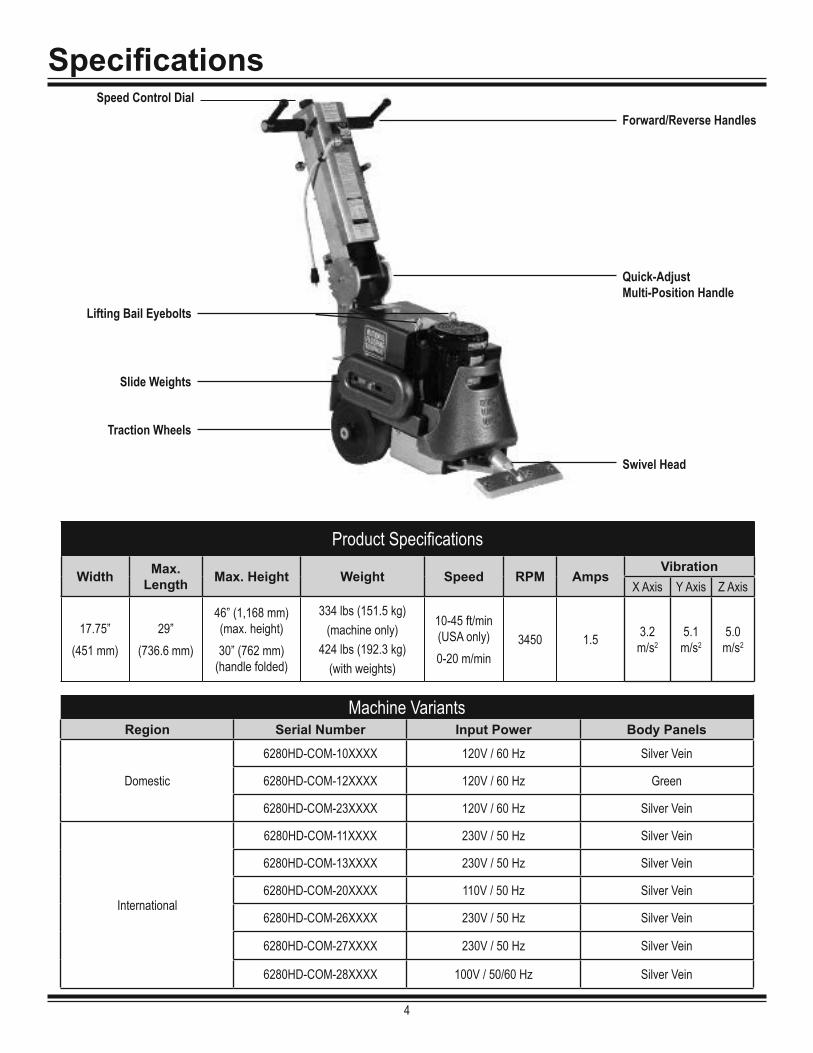
Specifications
4
Swivel Head
Lifting Bail Eyebolts
Slide Weights
Quick-Adjust Multi-Position Handle
Traction Wheels
Forward/Reverse HandlesSpeed Control Dial
Machine VariantsRegion Serial Number Input Power Body Panels
Domestic
6280HD-COM-10XXXX 120V / 60 Hz Silver Vein
6280HD-COM-12XXXX 120V / 60 Hz Green
6280HD-COM-23XXXX 120V / 60 Hz Silver Vein
International
6280HD-COM-11XXXX 230V / 50 Hz Silver Vein
6280HD-COM-13XXXX 230V / 50 Hz Silver Vein
6280HD-COM-20XXXX 110V / 50 Hz Silver Vein
6280HD-COM-26XXXX 230V / 50 Hz Silver Vein
6280HD-COM-27XXXX 230V / 50 Hz Silver Vein
6280HD-COM-28XXXX 100V / 50/60 Hz Silver Vein
Product Specifications
Width Max.Length Max. Height Weight Speed RPM Amps
VibrationX Axis Y Axis Z Axis
17.75”(451 mm)
29”(736.6 mm)
46” (1,168 mm) (max. height)30” (762 mm)
(handle folded)
334 lbs (151.5 kg)(machine only)
424 lbs (192.3 kg)(with weights)
10-45 ft/min (USA only)0-20 m/min
3450 1.5 3.2 m/s2
5.1 m/s2
5.0 m/s2

Safety
EnvironmentAvoid use in dangerous environments. Do not use in rain, damp or wet locations, or in the presence of explosive atmospheres (gaseous fumes, dust, or flammable mate-rials). Remove materials or debris that may be ignited by sparks. Keep work area tidy and well-lit - a cluttered or dark work area may lead to accidents. Extreme heat or cold may affect performance. Protect others in the work area and be aware of surroundings. Provide barriers or shields as needed to protect others from debris and machine operation. Children and other bystanders should be kept at a safe distance from the work area to avoid distracting the operator and/or coming into contact with the machine. Operator should be aware of who is around them and their proximity. Sup-port personnel should never stand next to, in front of, or behind the machine while the machine is running. Operator should look behind them before backing up.Do not come within 3 ft. of the machine’s perimeter during operation. Guard against electric shock. Ensure that machine is connected to a properly grounded outlet. Prevent bodily contact with grounded surfaces, e.g. pipes, radia-tors, ranges, and refrigerators. When scoring or making cuts, always check the work area for hidden wires or pipes.
5
GENERAL RULES FOR SAFE OPERATIONBefore use, anyone operating or performing maintenance on this equipment must read and understand this manual, as well as any labels pack-aged with or attached to the machine and its components. Read the manual carefully to learn equipment applications and limitations, as well as potential hazards associated with this type of equipment. Keep manual near machine at all times. If your manual is lost or damaged, contact National Flooring Equipment (NFE) for a replacement.
Personal Dress properly and use safety gear. Do not wear loose clothing; it may be caught in moving parts. Anyone in the work area must wear safety goggles or glasses and hearing protection. Wear a dust mask for dusty operations. Hard hats, face shields, safety shoes, etc. should be worn when speci-fied or necessary. Maintain control; stay alert. Keep proper footing and balance, and maintain a firm grip. Ob-serve surroundings at all times. Do not use when tired, distracted, or under the influence of drugs, alcohol, or any medication that may cause decreased control.Keep hands away from all moving parts and tooling. Wear gloves when changing tooling. Remove tooling when ma-chine is not in use and/or lower cutting head to the floor. Do not force equipment. Equipment will perform best at the rate for which it was designed. Excessive force only causes operator fatigue, increased wear, and reduced control.
EquipmentUse proper parts and accessories. Only use NFE-approved or recommended parts and accessories. Using any that are not recommended may be hazardous. Ensure accessories are properly installed and maintained.Do not permanently remove a guard or other safety device when installing an accessory or attachment. Inspect for damaged parts. Check for misalignment, binding of moving parts, loose fasteners, improper mounting, broken parts, and any other conditions that may affect operation. If abnormal noise or vibration occurs, turn the machine off immediately. Do not use damaged equipment until repaired. Do not use if power switch does not turn machine on and off. For all repairs, insist on only identical NFE replacement parts.Maintain equipment and labels. Keep handles dry, clean, and free from oil and grease. Keep cut-ting edges sharp and clean. Follow instructions for lubricating and changing accessories. Motor and switches should be completely enclosed at all times with no exposed wiring. Inspect cord regu-larly. Labels carry important information; if unreadable or missing, contact NFE for a free replacement. Avoid accidental starting; store idle equipment. When not in use, ensure that the machine is unplugged; do not turn on before plugging in. Store in a dry, secured place. Remove tooling when storing, and keep away from children.
Maintenance & RepairsBegin maintenance work only when the machine is shut down, unplugged, and cooled down. Use proper cleaning agents. Ensure that all cleaning rags are fiber-free; do not use any aggres-sive cleaning products.Schedule regular maintenance check-ups. Ensure machine is properly cleaned and serviced. Remove all traces of oil, combustible fuel, or cleaning fluids from the machine and its connections and fittings. Retighten all loose fittings found during maintenance and repair work. Loose or damaged parts should be replaced immediately; use only NFE parts. Do not weld or flame-cut on the machine during repairs, or make changes to machine without authorization from NFE.
CAUTION! ENSURE PROPER USE OF EXTENSION CORDS. IF AMP DRAW IS HIGHER THAN SHOWN ON TABLE OR CORD IS LONGER THAN 50 FT, SEE AN ELECTRICIAN. ASSUMPTIONS: 3% ALLOWABLE VOLTAGE DROP, COPPER CONDUCTORS RATED FOR 75OC, 1.25 SAFETY FACTOR, CORD VOLTAGE RATING OF 600VAC, PROPER CORD TYPES (STO, STOW, SOOW).
Amp Draw Gauge
0-12 1413-16 1214-24 1025-40 8
5

SafetyWALK-BEHIND SCRAPER SAFETY GUIDELINESBefore use, anyone operating this equipment must read and understand these safety instructions.
6
WARNING: GRINDING/CUTTING/DRILLING OF MASONRY, CONCRETE, METAL AND OTHER MATERIALS CAN GENERATE DUST, MISTS AND FUMES CONTAINING CHEMICALS KNOWN TO CAUSE SERIOUS FATAL INJURY OR ILLNESS, SUCH AS RESPIRATORY DISEASE, CANCER, BIRTH DEFECTS OR OTHER REPRODUCTIVE HARM. IF YOU ARE UNFAMILIAR WITH THE RISKS ASSOCIATED WITH THE PARTICULAR MATERIAL BEING CUT, REVIEW THE MATERIAL SAFETY DATA SHEET AND/OR CONSULT YOU EMPLOYER,
THE MATERIAL MANUFACTURER/SUPPLIER, GOVERNMENTAL AGENCIES SUCH AS OSHA AND NIOSH AND OTHER AUTHORITIES ON HAZARDOUS MATERIALS. CALIFORNIA AND SOME OTHER AUTHORITIES, FOR INSTANCE, HAVE PUBLISHED LISTS OF SUBSTANCES KNOWN TO CAUSE CANCER, REPRODUCTIVE TOXICITY, OR OTHER HARMFUL EFFECTS. CONTROL DUST, MIST AND FUMES AT THE SOURCE WHERE POSSIBLE. IN THIS REGARD USE GOOD WORK PRACTICES AND FOLLOW THE RECOMMENDATIONS OF THE MANUFACTURER/SUPPLIER, OSHA/NIOSH, AND OCCUPATIONAL AND TRADE ASSOCIATIONS. WHEN THE HAZARDS FROM INHALATION OF DUST, MISTS AND FUMES CANNOT BE ELIMINATED, THE OPERATOR AND ANY BYSTANDERS SHOULD ALWAYS WEAR A RESPIRATOR APPROVED BY OSHA/MSHA FOR THE MATERIAL BEING CUT.
ScrapingBeware of hidden obtrusions. Watch out for hidden dangers and protrusions in flooring. Do not use on largely uneven surfaces. Observe location of electrical supplies and extension cords. Do not allow cutting heads to come into contact with any electrical supply or extension cord. Use correct tooling and accessories. Provide barriers or shields as needed to protect others from debris. After mounting tooling, check for proper alignment. Use for correct applications. Do not force equipment to do heavier duty work than it was made for.
Safety
6

Safety
7
HYDRAULIC SAFETYMaintaining a Safe Work EnvironmentEstablishing a safe work environment in and around your hydraulic equipment is extremely important. The easiest and most effective way to avoid problems is to make sure associates understand their equipment, know how to operate the machines safely, and recognize the dangers if handled carelessly. A few things to be aware of are:
• Pressure: Hydraulic fluid under pressure is dangerous and can cause serious injury. Never look for a leak when unit is under pressure. Using your hand could cause serious injury. A few common ways to encounter hydraulic fluid under pressure include: ▪ Pinhole: Fluid under pressure can cause serious injury. It can be almost invisible escaping from a pinhole, and it can pierce the skin
into the body.
▪ Leak: Keep fittings and hoses tight. Only check and service when not under pressure. Leaking hydraulic fluid is hazardous; in addition to making workplace floors slippery and dangerous, it also contaminates the environment. Before cleaning an oil spill, always check EPA, state, and local regulations.
▪ Burst: Whether due to improper selection or damage, a ruptured hose can cause injury. If it bursts, a worker can be burned, cut, injected, or may slip and fall.
▪ Coupling Blow-Off: If the assembly is not properly made or installed, the coupling could come off and hit or spray a worker, possibly resulting in serious injury. Never operate machine without guards.
• Flammability: When ignited, some hydraulic fluids can cause fires and/or explode.With the exception of those comprised primarily of water, all hydraulic fluid is flammable (including many “fire-resistant” hydraulic fluids) when exposed to the proper conditions. Leaking pres-surized hydraulic fluids may develop a mist or fine spray that can flash or explode upon contact with a source of ignition. These explosions can be very severe and could result in serious injury or death. Precautions should be taken to eliminate all ignition sources from contact with escaping fluids, sprays or mists resulting from hydraulic failures. Sources of ignition could be electrical discharges (sparks), open flames, extremely high temperatures, sparks caused by metal -to -metal contact, etc.
• Mechanical: Hydraulic fluid creates movement, which means some equipment may move. Observe surroundings and equipment at all times.
• Moisture: Do not use in wet or high moisture conditions. • Electrical: Faulty wiring can be an electrical hazard. A regular preventive maintenance program should always include a wiring check. If
applicable, disconnect battery before serving.• Temperature: Because this machine operates at a relatively low pressure, overheating is not common. If surface of tank becomes too hot
to touch by hand (above 130ºF or 55°C), shut off machine and allow it to cool.
Hydraulic FluidOnly use Texaco Rando 46 Hydraulic Oil or compatible fluid like ISO or AW #46 from a brand name manufacturer. Non-compatible fluids could cause damage to unit or serious injury.
CAUTION: NEVER USE YOUR HANDS TO CHECK FOR LEAKS OVER HOSE OR HYDRAULIC CONNECTIONS. USE A PIECE OF CARD-BOARD TO LOCATE A PRESSURIZED LEAK. FOR LOW PRESSURE LEAKS (DRIPS), USE A RAG TO CLEAN THE AREA AND DETERMINE WHERE THE LEAK ORIGINATES.
DANGER: DO NOT TOUCH A PRESSURIZED HYDRAULIC HOSE ASSEMBLY WITH ANY PART OF THE BODY. IF FLUID PUNCTURES THE SKIN, EVEN IF NO PAIN IS FELT, A SERIOUS EMERGENCY EXISTS. OBTAIN MEDICAL ASSISTANCE IMMEDIATELY. FAILURE TO DO SO COULD RESULT IN LOSS OF THE INJURED BODY PART OR DEATH.
7

Troubleshooting Guide
8
Problem Cause SolutionMachine will not start. Insufficient power. Ensure use of properly rated extension cord.
Loose capacitor leads. Check capacitor leads to ensure good connection.
Overload button on motor has been tripped. Button is located on the bottom of the electric box on motor. If tripped, hold button in until it clicks.
Faulty ON/OFF switch. Replace if needed.
Machine will not move under power. Wheels are not in the “engage mode.” Install wheel pins for “engage mode.”
Broken belt. Remove wheels and bottom cover to inspect. Replace if needed.
Broken chain. Remove wheels and bottom cover to inspect; repair or replace if needed.
Control handle mechanism failure. Inspect control mechanism; repair or replace as needed.
Motor is humming, but machine does not run or breakers are blown.
Failed isolators. Remove wheels and bottom cover to inspect.
Failed capacitors. Replace as needed.
Motor start switch connections are dirty. Remove fan cover and fan. Clean the motor start switch (set of points) with an emery board or cloth between the points; reassemble.
Machine is leaking hydraulic fluid. Leak in hose(s). Tighten; replace if needed.
Hydraulic fittings are loose. Tighten; replace if needed.
Motor is heating up. Motor shaft is binding. Remove wheels and cover to inspect isolators. Inspect cutting head bearing and eccentric to ensure that they are not binding. If issue continues, contact NFE for additional support.
Machine won’t propel forward, only in reverse.
Speed control is set too slow. Turn speed control knob to the left (counterclockwise).
Shank doesn’t fit into angle attachment. Burrs inside angle attachment. Use round file until burrs are gone.
Damage to shank insert end. Remove damage with file or hand grinder. Replace shank if nessary.

Maintenance
9
WHEEL CLEANER ADJUSTMENT1. Loosen wheel cleaner with 9/16” wrench (Figure 1). 2. Slide cleaner up to the face of the wheel until it touches, but does not dig into the
wheel surface. 3. Re-tighten firmly. Note: Too much interference between the wheel and cleaner will
damage wheel.
WHEEL REMOVAL1. Turn off and unplug machine. 2. Examine back of wheels for built-up debris.3. Remove yarn build-up.4. Place block under machine between wheels.5. Disengage and remove axle pin (Figure 2).6. Remove wheel-securing screw with a 5/16” hex wrench (Figure 2).7. Remove wheel-securing cap. Wheel will slide off. 8. Remove wheel spacer. This should be inspected at regular intervals. 9. Relubricate bearing inside wheel before reassembly.
ADDING OR CHANGING HYDRAULIC FLUID• Change or add fluid when needed; check fluid level if there has been a leak, dam-
aged or ruptured hose, or a loose fitting. Fluid should be level with bottom of tank plug hole (Figure 3).
• To add fluid, unscrew filler port cap from top of machine (Figure 4.1); add fluid through a filter or funnel with a screen to keep fluid clean.
• To change fluid, remove filler port cap. Remove drain plug from side of machine (Figure 4.2). A 2 gallon (8 liter) container will be needed to drain the fluid into. (Fluid will not be removed from hoses.) Regardless of the machine’s straining system, add fluid through a filter or funnel with a screen to keep fluid clean.
INSPECTION OF INTERNAL PARTSVisual inspection of internal parts can be done without draining the tank.
1. Remove two lifting bail eyebolts and the two bolts from the back of the tank.2. Carefully lift tank 3-4’’ (8-10 cm).3. Using a flashlight, inspect the drive chain, hoses, front seal on hydraulic motor, and
suction and pressure line on pump.
4. If service is necessary, follow the procedure for tank removal.
FIG. 1
FIG. 2
FIG. 3
FIG. 4.2
WARNING: ALWAYS UNPLUG MACHINE BEFORE PERFORMING MAINTE-NANCE.
Wheel Cleaner
Axle PinWheel Securing Screw
TankPlug Hole
Filler Port Cap
DrainPlug
FIG. 4.1

MaintenanceTANK REMOVALIt is necessary to remove the tank in order to repair the pump, or to replace or service internal hoses.
1. Drain tank by removing the top filler port cap and drain plug on the side of the machine (Figure 12). A two gallon container will be needed to drain the fluid into.
2. Replace drain plug and filler port cap.3. Remove two lifting bail eyebolts and the two bolts from the back of the tank.4. Disconnect return line on the back of the tank; carefully lift tank 3-4’’ (8-10 cm) and disconnect suction line. The tank can now be removed.
POWER CORDIf the power cord is damaged, it must be replaced by NFE or a qualified professional.
ISOLATORSInspection
1. Perform the wheel removal procedure to access the bottom cover.2. Remove one wheel at a time; remove the bottom cover bolt behind each wheel.3. Carefully remove the bottom cover to expose the underside.4. Inspect the isolators from the side for damage or wear.
Replacement1. Remove the side slide weights, side weights, and front weight.2. Loosen the top five hex head bolts holding the isolators in place. Grip each isolator with locking pliers to aid in loosening.3. Remove and replace each isolator.
CUTTING HEAD BEARINGInspection
1. Perform the wheel removal procedure to access the bottom cover.2. Remove one wheel at a time; remove the bottom cover bolt behind each wheel.3. Carefully remove the bottom cover to expose the underside.4. Inspect the cutting head bearing for damage or wear.
Replacement1. Remove the bottom cover.2. Remove the cutting head bearing from the cutting head by removing the four bolts that hold down the bearing.3. Replace the cutting head bearing and re-tighten the four bolts.4. Place the bottom cover and re-tighten the eight bolts that hold the bottom cover in place.
10

Maintenance
11
Maintenance to be performedInterval
Daily 50 hrs 1000 hrs 2000 hrs
Inspect fasteners, wheels and blade holders for damage. ●
Clean built-up glue and debris from wheels, front weight, and blade holder. ●
Visually inspect internal parts. ●
Inspect safety devices and switches (power cord, wheel cleaners, switches). ●
Inspect and replace isolators. ●
Inspect and replace cutting head bearing. ●
Change hydraulic fluid. ● ○
○ - Perform maintenance at least once a year

Parts List and Diagrams
12
1
3
2
4
WEIGHTPARTS
PUMP PARTS
MOTOR PARTS
TANK PARTS
BODY PARTS
WHEEL PARTS
BOTTOM & BACK COVERS
ECCENTRIC, CHAIN ANDBELT PARTS
6
5
CUTTING HEAD PARTS
ITEM NO.
6280
HD-1
1XXX
X62
80HD
-13X
XXX
6280
HD-2
6XXX
X62
80HD
-27X
XXX
6280
HD-2
8XXX
X
6280
HD-1
0XXX
X62
80HD
-12X
XXX
6280
HD-2
3XXX
X
6280
HD-2
0XXX
X
DESCRIPTION QTY.
1
403778 Assembly, Commander Handle, 230V 1403731 Assembly, Commander Handle, 100V, Japan 1
401577 Assembly, Commander Handle, 115V 1403825 Assembly, Commander Handle, 110V, UK 1
2 6280HD-HYDMOTOR Motor, Hydraulic, Sub, 6280HD 13 6280-401B Wrench, Allen, 7/32 14 73222 Bolt, Flange 3/8-16 x 1 35 6280HD-250 Assembly, Transport Wheel, 6280HD 16 6280HD-BASEASSY Base Assembled, 6280HD 1
OVERALL MACHINE

Parts List and Diagrams
13
219
5
7
3
4 5
6
10
78
ITEM NO.
6280HD-10XXXX6280HD-11XXXX6280HD-13XXXX6280HD-20XXXX6280HD-23XXXX6280HD-26XXXX6280HD-27XXXX6280HD-28XXXX
6280HD-12XXXX DESCRIPTION QTY.
16280-162-SV Tank, Hydraulic, Weldment, Silver Vein 1
6280-162-G Tank, Hydraulic, Green 12 6280-162G 6280-162G Magnet, Tank 13 6280-161B 6280-161B Plug, Vent, Filler Cap 14 6280-161D 6280-161D Plug, Filler Port 15 6280-214 6280-214 Plug, Tank 26 72816 72816 Fitting, Elbow, 90 Deg. 3/8 17 401452 401452 Washer, Flat, 1/2", SAE 88 70601 70601 Strainer, Tank Mounted 19 403882 403882 Eye Bolt, 1.50 ID, 3/8-16 x 8 210 73222 73222 Bolt, Flange 3/8-16 x 1 2
TANK

Parts List and Diagrams
14
5
3
1
2
8
6
4
ITEM NO.
6280HD-10XXXX6280HD-11XXXX6280HD-12XXXX6280HD-13XXXX6280HD-20XXXX6280HD-23XXXX6280HD-26XXXX6280HD-27XXXX
6280HD-28XXXX DESCRIPTION QTY.
172362 Motor, 1-1/2 HP, 115/230 Volt 1
403307 Motor, 1-1/2 HP, 100 VAC, 50/60 Hz, 1725/1425 RPM 1
2 6280-179 Ring, Motor Spacer 13 73502 Strain Relief, Straight 1/2 in 14 73401 Nut, Strain Relief, Steel, 1/2" 15 74730 Grommet, Rubber 5/8" 16 73201 Screw, Hex Head Cap, 3/8-16 x 1 48 73204 Washer, Lock, 3/8 4
MOTOR
4
1
3
5
6
2
ITEM NO.
6280HD-11XXXX6280HD-13XXXX6280HD-26XXXX6280HD-27XXXX
6280HD-10XXXX6280HD-12XXXX6280HD-20XXXX6280HD-23XXXX6280HD-28XXXX
DESCRIPTION QTY.
170925 Pump, Spline, #7 1
6280-113S Pump, Spline, #4 12 6280-117 6280-117 Fitting, Pump 13 6280-118 6280-118 Fitting, Suction Hose to Pump 14 6280-119 6280-119 Spacer, Pump 15 6280-120 6280-120 Suction Hose 16 73223 73223 Bolt, Flange 3/8-16x1-1/4 2
PUMP

Parts List and Diagrams
15
8
7
2
3
1
96
5
4
ITEM NO. PART NUMBER DESCRIPTION QTY.
1 6280-156L Body, Main, Upper, Left 12 6280-156R Body, Main, Upper, Right 13 6280HD-165 Cleaner, Wheel 24 74763 Grommet, Rubber 1/2" 15 73201 Screw, Hex Head Cap, 3/8-16 x 1 86 73204 Washer, Lock, 3/8 87 73303 Washer, Split Lock 5/16 48 73311 Screw, Socket Head Cap, 5/16-18 x 1 49 73264 Washer, Flat, Zinc USS 3/8 4
BODY
5
1
3
4
2
6
ITEMNO. PART NUMBER DESCRIPTION QTY.
1 73330 5/16 X 2.0 Lock Pin 12 L191 Label Caution 13 73402 Nut, Nylock 1/2-13 24 6280HD-300 BRACKET, TRANSPORT WHEELS 15 73425 Washer, Flat USS Zinc 1/2 46 6280-301 Caster Assy, Swivel, 3-inch, Stem 2
TRANSPORT WHEEL ASSEMBLY

Parts List and Diagrams
16
2
1
4
5 6 10
9
8
7910
3
ITEM NO.
6280HD-10XXXX6280HD-11XXXX6280HD-13XXXX6280HD-20XXXX6280HD-23XXXX6280HD-26XXXX6280HD-27XXXX6280HD-28XXXX
6280HD-12XXXX DESCRIPTION QTY.
1401564-SV Weight, Counter, Front, Silver Vein 1
401564-G Counterweight, Front, Cast, Green 12 402225 402225 Bolt, Hex Head Cap 3/8-16 X 5-1/2 23 73263 73263 Washer, Flat SAE Zinc 3/8 2
474851-SV Weight, Slide, Silver Vein 2
74851-G Weight, Slide, Green 15 6280HD-109 6280HD-109 Spacer, Weight 46 74853-BLK 74853-BLK Side Weight, Black 27 400159 400159 Bolt, Socket Head Cap Screw, 1/2-13 x 3-3/4 48 73426 73426 Bolt, Hex Head Cap 1/2-13x4-3/4 29 73403 73403 Washer, Split lock 1/2 6
10 73424 73424 Washer, Flat, Zinc SAE 1/2 6
WEIGHTS

Parts List and Diagrams
17
2
6
3
5
4
6
1
7
6
5
ITEM NO. PART NUMBER DESCRIPTION QTY.
1 6280-139 Cover, Rear 12 6280HD-138 Cover, Main Bottom 13 71118 Bearing, Flange 14 73211 Nut, Flange, Serrated, 3/8-16 115 73222 Bolt, Flange 3/8-16 x 1 146 73318 Bolt, Wizlock Flange 5/16-18x5/8 107 73223 Bolt, Flange 3/8-16x1-1/4 8
BOTTOM AND BACK COVERS
1
2
35
4
ITEM NO. PART NUMBER DESCRIPTION QTY.
1 402592 Wheel, Drive, Siped, Heavy Duty, 8.25 x 2.75 22 402311 Pin, Lynch, 5/16 x 2-1/16 23 6280-112 Cap, Wheel 24 6280HD-112 Spacer, Wheel 25 73313 Screw, Flat Head Socket Cap 5/16-18x1/2 2
WHEELS
ITEMNO. PART NUMBER DESCRIPTION QTY.
1 6280-125W Bracket and Pin, Idler Mount 12 71072 Bearing, 1/2 ID DCTN-1616 2
3 6280-126A Cap, Idler Bearing 1
4 73003 Screw, Button Head Socket Cap 1/4-20x5/8 1
1 3 422
IDLER MOUNT

ITEMNO. PART NUMBER DESCRIPTION QTY.
1 6280HD-225 Motor, Hydraulic 12 6280-225 Spacer, Hydraulic Motor 13 71115 Bearing, 1x2x1/2 14 6280-226 Bracket, Mounting, Hydraulic Motor 15 401541 Sprocket, Axle, Heavy Duty 16 73012 Screw, Set, 1/4-20 x 3/8 27 6280-221 Connector, Hydraulic Motor 28 73222 Bolt, Flange 3/8-16 x 1 49 6280-223 Key, Shaft, Hydraulic Motor 1
56
1
4
7
23
8
9
HYDRAULIC MOTOR
Parts List and Diagrams
18
4
2
1
3
8 7 5
6
ITEM NO. PART NUMBER DESCRIPTION QTY.
1 6280-125 Assembly, Idler 12 6280-229 Link, Master, Drive Chain 13 6280HD-108 Belt, Pump Drive 14 6280HD-228 Chain, Drive 15 6280HD-400 Eccentric 16 73044 Screw, Cup Point Socket Set 1/4-20 x 5/8 37 73218 Bolt, HHCS, 3/8-24x.75 18 73215 Washer, External Lock 3/8 1
ECCENTRIC, CHAIN AND BELT

Parts List and Diagrams
19
141
1210
9
3
2
8
6
45
7
11
13
15
16
17
ITEM NO. PART NUMBER DESCRIPTION QTY.
1 6280HD-107 Plate, Base, 6280HD 12 402210 Pump Drive Assy, Splined, HD 13 6280-103A Ring, Retaining, Ext, Axial, 1" 14 6280HD-102 Ring, Axle Snap 45 6280HD-103 Axle, Drive 16 6280HD-104 Sprocket, Axle 17 6280HD-105L Support, Axle Bearing, Left 18 6280HD-105R Support, Axle Bearing, Right 19 70810 Isolator, Vibration 910 71115 Bearing, 1x2x1/2 111 71128 Bearing, 1-1/8ID R18-2RS 212 71132 Bearing, 1-1/4 113 73033 Key, 1/4 x 1/4 x 1" 114 73217 Screw, Socket Head Cap, Low, 3/8-16 x 3/4 915 73310 Screw, Socket Head Cap, Grade 5 5/16-18x7/8 416 6280HD-145 Cover, Front 117 73318 Bolt, Wizlock Flange 5/16-18x5/8 2
BASE

Parts List and Diagrams
20
CUTTING HEAD
1
6
2
5
3
4
7
BASE
ITEM NO.
6280HD-10XXXX 6280HD-11XXXX 6280HD-12XXXX 6280HD-13XXXX 6280HD-20XXXX 6280HD-23XXXX 6280HD-26XXXX 6280HD-27XXXX 6280HD-28XXXX
DESCRIPTION QTY.
1 402276 Attachment, Sub, 9 Degree Angle 12 6280HD-1 Plate, Base, Cutting Head 1
6280HD-145 Cover, Front 173318 Bolt, Wizlock Flange 5/16-18x5/8 2
3 71141 Bearing, 1-7/16" ID 16SC4FB Dodge Housing Assy 14 73423 Washer, Interior/Exterior Lock 1/2" 45 73211 Nut, Flange, Serrated, 3/8-16 96 73222 Bolt, Flange 3/8-16 x 1 57 73418 Bolt, Hex Head 1/2-20x1 4

Parts List and Diagrams
21
ITEM NO.6280(HD)-10XXXX6280(HD)-12XXXX6280(HD)-23XXXX
6280(HD)-11XXXX6280(HD)-13XXXX6280(HD)-15XXXX6280(HD)-20XXXX6280(HD)-26XXXX6280(HD)-27XXXX6280(HD)-28XXXX
DESCRIPTION QTY.
1 6280-601 6280-601 Weldment, Upper Handle 1
2 401588 Cord, Handle, Commander, 6280, 110V 1401589 Cord, Handle, Commander, 6280, 220V
2
HYDRAULICPARTS
FRONT COVER
1
ADJUSTMENTROD PARTS
LOWER SUBASSYPARTS
KNOB PARTS
LEVER PARTS
INTERNATIONAL
DOMESTIC
UPPER HANDLE ASSEMBLY

ITEMNO.
6280(HD)-10XXXX6280(HD)-12XXXX6280(HD)-23XXXX
6280(HD)-11XXXX6280(HD)-13XXXX6280(HD)-15XXXX6280(HD)-20XXXX6280(HD)-26XXXX6280HD-27XXXX
6280(HD)-28XXXX
DESCRIPTION QTY.
1 400056 Bolt, Hex Head 1/2-13x6-1/2 32 73424 Washer, Flat, Zinc SAE 1/2 63 6280-600 403816 Plate, Index, Handle 24 400077 Gasket, Handle 25 6280-618 Tube, Spacer, Long 16 401629 Handle, Lower, Rack Pins 17 6280-619 Spacer Tube, Short 28 73402 Nut, Nylock, 1/2-13 3
1 2 354
67
82
LOWER SUB-ASSEMBLY
Parts List and Diagrams
22
2
31
4
ITEMNO. PART NUMBER DESCRIPTION QTY.
1 400031 Hose, Hydraulic, 1/4 x 40, F/90F 12 400033 Hose, Hydraulic, 3/8 x 36, F/F 13 400032 Hose, Hydraulic, 1/4 x 33, F/90F 14 400032 Hose, Hydraulic, 1/4 x 33, F/90F 15 400097* Wrap, Kevlar 21"
2
3
4
1
*NOT SHOWN
HYDRAULIC HOSES

Parts List and Diagrams
23
10
8
15
614
7
13
15
3
16
4
4
2
2
15
16
179
16
11
12
ITEMNO. PART NUMBER DESCRIPTION QTY.
1 400024 Grip, Foam, 1" 22 400034 Fitting, FF1231-06-08 23 401434 Linkage, Valve, Handle 14 5280-118 Fitting, 90 Degree 25 6280-607 Bushing, Handle Bar 26 6280-608 Weldment, Handle Bar 17 6280-613 Bracket, Valve Connector 18 70623 Grip, Foam 29 70624 Valve, Single Spool, Tapered 110 70636 Lever, Adjustable, Right Hand 111 70637 Lever, Adjustable, Left Hand 112 73351 Washer, Flat, 5/16, SAE 213 73008 Nut, Nylock 1/4-20 214 73066 Bolt, SHCS, 1/4-20x1.75 215 73334 Bolt, Hex Head Cap 5/16-18x1-1/2 216 73322 Nut, Nyloc, 5/16-18 417 73327 Bolt, Hex Head Cap 5/16-18x2 1/2 2
LEVER

Parts List and Diagrams
24
14
2 916
16
12
12
3
11
1
64
10
ITEMNO.
6280
(HD)
-10X
XXX
6280
(HD)
-12X
XXX
6280
(HD)
-23X
XXX
6280
(HD)
-11X
XXX
6280
(HD)
-15X
XXX
6280
(HD)
-26X
XXX
6280
(HD)
-13X
XXX
6280
(HD)
-20X
XXX
6280
(HD)
-27X
XXX
6280
(HD)
-28X
XXX
DESCRIPTION QTY.
1 6280-602 403777 403777 403777 403777 403777 Cover, Upper Handle 12 6280-207 403776 403776 403814 403776 403815 Switch, On-Off 13 6280-404 6280-404 6280-404 6280-404 6280-404 6280-404 Holder, Blade Wrench 14 72873 72873 72873 72873 72873 72873 3/8 Cable Clamp 15 401682 N/A N/A N/A 401682 N/A Connector, 1/2", 90 Degree 16 74413 74413 74413 74413 74413 74413 Washer,Internal Lock #10 1
76280-168
N/A N/A N/A N/ACord, Power, New Style
1402839 Cord, Power, UK1-13P, BS1363A, Angle
Plug, 13A 250 Volt8 92819 92819 92819 92819 92819 92819 Disconnect, Quick, Nylon, 16-14 Gauge 29 72812 72812 72812 72812 72812 72812 Disconnect,12-10 Gauge, Female, Nylon 110 73301 73301 73301 73301 73301 73301 Bolt, Button Head Socket Cap 5/16-18x1/2 111 74406 74406 74406 74406 74406 74406 Screw, Phillips Pan Head 10-32x3/8 112 74619 74619 74619 74619 74619 74619 Washer, Lock, M6 613 73401 N/A N/A N/A 73401 N/A Nut, Strain Relief, Steel, 1/2" 114 N/A 403797 403797 403797 N/A 403797 Screw, Phillips Pan Head, M5-0.8 x 50mm 215 N/A 401438 72715 403870 N/A 403719 Power Cord Plug 116 74630 74630 74630 74630 74630 74630 Bolt, Hex Head Cap M6-12 8.8 6
15
7
10
4
9
5
1612
11
63
12
1628 1
13
FRONT COVER

Parts List and Diagrams
25
ITEMNO. PART NUMBER DESCRIPTION QTY.
1 6280-606 Handle, Ball 12 92800-98 Rod, Adjustment, Short 13 92800-99 Collar, Adjustment Rod 14 92800-12 Spring, Adjustment, 3.5" 15 402201 Washer, .625 ID x 1.000 OD 16 402197 O-ring, .489 ID X .629 OD X .070 W 27 402200 E-Clip, Shaft, .625 18 402219 Rod, Adjustment, Large, 3X Groove 19 6280-611 Lock, Adjustment Bar 1
1
5
8
7
9
4
6
2
3
6
ADJUSTMENT ROD
ITEMNO. PART NUMBER DESCRIPTION QTY.
1 70638 Knob, Adjustable, 1-1/4" 12 73263 Washer, Flat SAE Zinc 3/8 13 402290 Spring, .66"OD x 1.50"L x .049"w 14 402256 Sleeve, Knob, Commander Handle 15 401997 Stopper, Speed Control 16 400340 Screw, 6-32 x 3/16 SSS CP 1
1
3
4
5
6
2
SPEED CONTROL KNOB

Parts List and Diagrams
26
WIRING
1
2
HANDLE
FEMALETWIST PLUG
GRNWHT
U1 U3 Z8 U2 Z5U4
GND
WHITEDPST
MALETWIST PLUG
BLK
GRNWHT
BLK
3 WIRE CABLE.
MOTOR
P1 BLK
P2U1
WALL PLUG
BLACK
GREEN
SWITCH
3

Parts List and Diagrams
27
HYDRAULICS
A
B
PA
TB
HYDRAULICMOTOR
HYD.PUMP
FLUID TANK
HYDRAULIC VALVE
FWD. PRESS.FLOW
REV. PRESS.FLOW
POSITIVEPRESSURE
SUCTION(NEGATIVE PRESS.)
TO TOP OF TANK.
BLEED

Warranty
28
National Flooring Equipment Inc. (referred to as “the Company”) warrants that each new unit manufactured by The Company, to be free from defects in material and workmanship in normal use and service for a period of twelve (12) months from date of shipment from the Company. For administrative ease, will honor warranty for a period of fifteen (15) months from date of shipment from the company. Accessories or equipment furnished and installed on the product by the Company but manufactured by others, including but not limited to: engines, motors, electrical com-ponents, transmissions etc., shall carry the accessory manufacturers own warranty. Battery warranties are prorated over the warranty period. Customer is responsible for the inspection of equipment / parts upon delivery. Freight damages reported beyond authorized time frame will not be honored.
The Company, at its determination of defect, will repair or replace any product or part deemed to be defective in material or workmanship within specified warranty time period. All product determinations and / or repairs will take place at the designated Company repair facility, or at a certi-fied warranty location designated by the Company. The Company will coordinate and be responsible for all freight expenses associated with valid warranty claims. Freight and shipping expenses associated with abuse or misuse will be back charged to the Distributor/Customer. The Company reserves the right to modify, alter or improve any part / parts without incurring any obligation to replace any part / parts previously sold without such modified, altered or improved part / parts. In no event shall the seller or manufacturer of the product be liable for special, incidental, or consequential damages, including loss of profits, whether or not caused by or resulting from the negligence of seller and / or the manu-facturer of the product unless specifically provided herein. This warranty shall not apply to any products or portions there of which have been subjected to abuse, misuse, improper installation or operation, lack of recommended maintenance, electrical failure or abnormal conditions and to products which have been tampered with, altered, modified, repaired, reworked by anyone not approved or authorized by the Company or used in any manner inconsistent with the provisions of the above or any instructions or specifications provided with or for the product. Any and all unauthorized onsite warranty work conducted by unauthorized personnel or any outside person(s), is not covered by the Company unless the work has been pre-authorized by a predetermined manufacturer representative. This excludes wearable parts and/or consumables.
Defective or failed material or equipment shall be held at the purchaser’s premises until authorization has been granted by the Company to return or dispose of defective products. Products returned for final inspection must be returned with a manufacturer authorized Return Material Authorization (RMA). Any unauthorized return of equipment will be declined at the dock by the Company. Any non-approved items returned with approved returned items are subject to rejection and will not be credited. Credit will be issued for material found to be defective upon the Company’s inspection based on prices at time of purchase.
TO OBTAIN SERVICE CONTACT NATIONAL FLOORING EQUIPMENT, INC. TOLL FREE AT 800-245-0267 FOR A REPAIR AUTHORIZATION NUMBER. COD FREIGHT RETURNS WILL NOT BE ACCEPTED. FREIGHT COLLECT SHIPMENTS WILL NOT BE ACCEPTED. WARRANTY REPAIRS MUST BE ACCOMPANIED BY DATE OF PURCHASE RECEIPT AND A RETURN/REPAIR AUTHORIZATION NUMBER.
RETURN/REPAIR AUTHORIZATION NUMBER: _____________________________MACHINE SERIAL NUMBER: ____________________________________________


9250 Xylon Avenue N • Minneapolis, MN 55445 • U.S.A. Toll-free 800-245-0267 • Phone 763-315-5300 • Fax 800-648-7124 • Fax 763-535-8255
Web Site: www.nationalequipment.com • E-Mail: [email protected]