Embed Size (px)
Citation preview
Journal of the Mechanics and Physics of Solids 56 (2008) 1624–1650
Modelling of dynamic ductile fracture and application to the
simulation of plate impact tests on tantalum
C. Czarnotaa, N. Jacquesb, S. Merciera,�, A. Molinaria
aLaboratoire de Physique et Mecanique des Materiaux, UMR CNRS 7554, Universite Paul Verlaine - Metz, Ile du Saulcy,
57045 Metz Cedex, FrancebLaboratoire de Mecanique des Structures Navales, ENSIETA, 2 rue Franc-ois Verny, 29806 Brest Cedex 9, France
Received 16 March 2007; received in revised form 11 July 2007; accepted 18 July 2007
Abstract
A model of dynamic damage by void nucleation and growth is proposed for elastic–viscoplastic materials sustaining
intense loading. The model is dedicated to ductile materials for which fracture is caused by microvoiding. The material
contains potential nucleation sites where microvoids are generated when the local pressure overcomes the nucleation
pressure. A probability density function is adopted to describe the fluctuation of the nucleation pressure within the
material. The void growth is described by using a hollow sphere model where micro-inertia effects are accounted for. The
matrix weakening due to void growth is also included.
The model has been first tested under uniaxial deformation. When the strain rate is assumed constant, the pressure inside
the material has nearly a linear response up to a maximum. An analytical expression for the maximum pressure is
proposed.
Finite element simulations of plate impact tests have been carried out and compared to experiments on tantalum. From
simulations based on the proposed model, an increase of the spall strength is observed with higher shock intensities.
Therefore, the relationship between the velocity pullback and spall strength usually assumed in the literature (based on the
acoustic approach) seems to be inadequate. Velocity profiles are simulated for different flyer thicknesses and different
impact velocities with close agreement with experiments.
r 2007 Elsevier Ltd. All rights reserved.
Keywords: Spall; Plate impact; Dynamic ductile fracture; Inertia effects; Tantalum
1. Introduction
Spall fracture is a dynamic fracture process that occurs in several fields such as: armor penetration, collision
of particles against satellite, laser induced shock. In laboratories, the spall fracture is conventionally obtained
when a target plate is impacted by a flyer plate. During impact, compressive shock waves are generated in the
two plates. As they encounter the free surface of the target and of the flyer, they reflect back in rarefaction
waves. In the spall plane, where these waves interact, a large tensile stress is generated and spalling is initiated.
ARTICLE IN PRESS
www.elsevier.com/locate/jmps
0022-5096/$ - see front matter r 2007 Elsevier Ltd. All rights reserved.
doi:10.1016/j.jmps.2007.07.017
�Corresponding author. Tel.: +33 03 87 31 54 09; fax: +33 03 87 31 53 66.
E-mail address: [email protected] (S. Mercier).
More details are available in Meyers and Aimone (1983) and Antoun et al. (2003) who provide an overview on
various aspects of spalling.
Numerous experimental studies have been performed on different materials and for different flyer plate
velocities. Kanel et al. (1997) performed plate impact tests on aluminium and magnesium over a wide range of
loading duration and temperature; see also Seaman et al. (1976). Other materials have been tested, see for
example Boidin et al. (2006) for titanium alloys, Cochran and Banner (1977) for uranium, Steinberg and Sharp
(1981) for beryllium, Seaman et al. (1976) and Johnson (1981) for copper and Zurek et al. (1996), Roy (2003)
and Llorca and Roy (2003) for tantalum. Since no direct damage measurement can be done in situ during the
short duration of the impact test (order of a microsecond), the fracture mechanism is rather deduced from
external measurements such as the free-surface velocity of the target. VISAR interferometry is generally used
to get the free-surface velocity profile of the sample. From this measurement, the spall strength is generally
related to the amplitude of the velocity pullback (difference between maximum and minimum velocities of the
free surface). Zurek et al. (1996) noticed that a sharp velocity pullback indicates that the material has
undergone a complete separation. Eftis et al. (1991) in a first attempt to model spall experiments on OFHC
copper, mentioned that the amplitude of the pullback signal is related to the amount of tensile stress relaxation
and then to the corresponding level of damage. They considered that the damage is cumulated very rapidly in
0.05–0:06ms for the following conditions: flyer thickness 0.6mm, target 1.6mm and impact velocity 160m/s. In
fact, the fracture mechanism is complex. Kanel and co-workers have performed numerous spall experiments
(these results are presented in Antoun et al., 2003). From free-surface velocity measurements and
metallographic examinations of spalled specimens, Kanel and co-workers have observed that a velocity
pullback occurs even when a very low damage is observed in the spall plane. The stress relaxation due to the
initiation of the damage is responsible for the pullback. Due to relaxation, the subsequent damage is therefore
cumulated at lower stress magnitude and complete fracture occurs latter during the test. The dynamic damage
model developed in the present paper agrees with these observations.
In ductile materials, damage occurs by nucleation and growth of microvoids. Lots of theoretical models
have been devoted to couple void growth to elastic–(visco)plastic material properties. Under quasi-static
conditions, McClintock (1968), Rice and Tracey (1969) and Huang (1991) have analysed the evolution of a
spherical void in an infinite or finite matrix. Lee and Mear (1994) have determined the evolution of ellipsoidal
cavities in a finite matrix. Since in impact experiments, the level of pressure is high with respect to the tensile
yield stress, voids are observed to remain spherical, Antoun et al. (2003) and Roy (2003). As a consequence, no
deviation from spherical shape will be considered in our analysis.
The dynamic expansion of a single spherical void in an unbounded solid under hydrostatic tension was
analysed by Ortiz and Molinari (1992). These authors found that inertia dominates the late stage of cavity
growth whereas the early stage is controlled by strain rate and strain hardening effects. Inertia has a significant
role when voids reach a characteristic size. For dynamic evolution of a void in a bounded matrix, pioneering
works are those of Knowles and Jakub (1964) and Carroll and Holt (1972), see also Tong and Ravichandran
(1995). These authors investigated the dynamic response of a hollow sphere under spherical tensile or
compressive loading. Inertial effects are shown to be an important feature for high loading rates. In Carroll
and Holt (1972), the matrix material is elastic perfectly plastic. Johnson (1981) extended the previous work by
considering a rate-dependent material, the flow stress of the matrix being an affine function of the strain rate.
Inertia effects are shown to be negligible and void growth is shown to be controlled by viscosity. These results
could be due to the large strain rate sensitivity considered in this work (roughly equal to one), value which is
unrealistic for metallic materials. Perzyna (1986) revisited the Johnson (1981) contribution by including strain
hardening. Cortes (1992) generalized the two approaches by considering various viscoplastic descriptions of
the flow stress. Recently, Molinari and Mercier (2001) have developed a hollow sphere model, which accounts
for the viscoplastic behaviour of the matrix material and for inertia effects associated to the rapid void growth.
They found that the macroscopic stress has two contributions which are both porosity dependent: a quasi-
static part, which can be derived from any existing quasi-static potential, and an inertia-dependent part, see
also Wang and Jiang (1997), Leblond and Roy (2000) and Weinberg et al. (2006).
All previous models consider that the material is initially voided. For a pertinent physical description of
spalling, void nucleation has to be accounted for. Cavitation occurs when the applied pressure reaches a
critical value above which void growth is unbounded. Ball (1982) was the first to examine cavitation in
ARTICLE IN PRESS
C. Czarnota et al. / J. Mech. Phys. Solids 56 (2008) 1624–1650 1625
nonlinear elastic solids. In elastic–plastic solids, cavitation is driven by the elastic energy of the surrounding
material. Early works on cavitation instabilities are summarized in Hill (1950) and other developments are
found in Horgan and Polignone (1995), Huang et al. (1991) and Tvergaard et al. (1992). In a recent work, Wu
et al. (2003) have clearly analysed the dependence of the nucleation pressure upon elastic and thermoplastic
properties of the matrix material.
From observations on specimens recovered after shock, the distribution of void radii can be measured.
Bontaz-Carion and Pellegrini (2006) have quantified the damage in the target after plate impacts, using X-ray
microtomography. By means of this technique, they obtained three-dimensional images for the pore volume
distribution. Roy (2003) observed on tantalum that the microvoids are located near the spall plane with a
heterogeneous size distribution. In addition, the number of microvoids per unit volume increases strongly with
the shock pressure. Seaman et al. (1976) have observed, from metallographic examinations, that the number of
voids (per unit volume) with radii greater that a given radius R is decreasing exponentially with R. From tests
at different stress levels and durations, the nucleation rate is found to increase exponentially with pressure. In
addition, the void growth, based on the expansion of a void in a viscous fluid, is assumed to be an affine
function of the pressure level. Based on this nucleation and growth scheme (NAG), Seaman et al. (1976) were
able to estimate the total volume of voids and the porosity in the plate during impact tests. Note that micro-
inertia is not included in their approach. Recently, Molinari and Wright (2005) have considered the case of a
material initially free of voids. Potential sites for nucleation are present in the material and a void nucleates at
a potential nucleation site when the local pressure overcomes a critical nucleation pressure. Nucleation
pressures are assumed to follow a statistical distribution. The growth of nucleated voids is governed by micro-
inertia. In the model of Molinari and Wright (2005), each void is considered as isolated and is therefore
embedded in an infinite matrix. Thus, inertia effects are overestimated. Czarnota et al. (2006) revisited the
work of Molinari and Wright (2005) by considering that void growth is based on the dynamic response of a
hollow sphere and by accounting for the matrix softening due to the increase of porosity. To some extent, void
interactions could be accounted for in this approach. The spall strength of a high purity grade tantalum was
then predicted when assuming the loading in the spall plane to be a pressure ramp.
To simulate plate impact experiments and to account for wave propagation, damage models based on the
above theoretical works have been implemented in different numerical codes. Johnson (1981) carried out one-
dimensional finite difference calculations of the plate impact test and compared results with experiments
performed on copper. The material response was assumed elastic–plastic, the yield strength being porosity
dependent. The Mie–Gruneisen equation of state was adopted to describe the relation between pressure and
volume strain. Since the Mie–Gruneisen approach was developed for solid response with no permanent
inelastic volume strain, a modified equation was proposed which integrates the inelastic volume strain
generated by the porosity. Inertial effects during the rapid expansion of microvoids were taken into account.
Velocity profiles obtained with the numerical model were in agreement with experiments on copper. Eftis and
Nemes (1991), based on the Perzyna (1986) model, performed one-dimensional finite element calculations of
the plate impact problem, for two plates made of OFHC copper. The void growth rate has two contributions:
a nucleation term governed by thermally activated mechanisms (Seaman et al., 1976; Curran et al., 1987) and a
growth rate term. As in Perzyna (1986), the void growth is governed using a quasi-static approximation and
micro-inertia is disregarded. The justification of this approximation is based on Johnson (1981) who observed
that the void growth is dominated by plastic deformation rather than by micro-inertia. From one-dimensional
finite difference simulations, the authors evaluated the evolution of the axial stress in the plate after impact.
They observed a softening of the tensile wave in the spall plane as the damage is cumulated. They showed that
the entire spall process, from the beginning of damage development to the occurrence of the spallation
(obtained when a critical void volume fraction was reached), took approximately 0:06ms. Recently, Eftis et al.
(2003) investigated the hypervelocity projectile-target impact. For the projectile velocity considered (6 km=s),the material remains in the solid state. Contrary to plate impact at moderate velocities, the effect of
temperature cannot be disregarded. The deviatoric stress tensor evolution is governed by the Perzyna (1963)
model. The mean stress is related to the total volume strain and energy through a Mie–Gruneisen type
equation. Note that Johnson (1981) was using some similar approach for the mean stress but has modified this
relation in order to take into account the softening due to the inelastic volume change generated by void
growth. This is not the case in Eftis et al. (2003) approach. Void growth is governed by a relationship where
ARTICLE IN PRESS
C. Czarnota et al. / J. Mech. Phys. Solids 56 (2008) 1624–16501626

micro-inertia is present. Using the proposed approach, these authors simulated the impact of spherical glass
projectiles on an aluminium 1100 rectangular target plate. The simulated and experimental damages were
comparable. Numerous other approaches, not related to micro-inertia effects, have also been developed to
simulate spall experiments, Cochran and Banner (1977), Curran et al. (1987), Rajendran et al. (1989), Feng et
al. (1997), Lin et al. (2004), Suffis (2004), Campagne et al. (2005). One may refer to Chen et al. (2005) who
carried out one-dimensional simulations of impact experiments. They mentioned that the wave profile in the
target from the spall plane to the free surface is affected seriously by the stress relaxation due to damage
evolution. They concluded that the traditional determination of the spall strength (related to the pullback
velocity) without accounting for stress relaxation has to be used with caution. Note also the work of Ikkurthi
and Chaturvedi (2004) for a comparison of different models used for plate impact simulations.
In the present paper, a new constitutive damage model is proposed for the dynamic fracture of ductile
materials. The model of void nucleation and growth proposed by Czarnota et al. (2006) is extended to account
for elastic–viscoplastic material response (see also Wright et al., 2005). In the next section, the model is
presented and the general equations are formulated. The proposed model has been implemented in the finite
element software ABAQUS/Explicit. By simulations of plate impact tests, the damage evolution near the spall
plane can be analysed in details. Special attention is paid to the explanation of the pullback signal observed on
the free-surface velocity and the correlation with damage evolution. Finally, a comparison of the simulated
free-surface velocity profile with experimental data of Roy (2003) is carried out for a high purity grade
tantalum. The present approach integrates physical concepts such as progressive nucleation and void growth
governed by micro-inertia. Most of the model parameters are obtained from experimental data. In the
literature, numerous works have been dedicated to spallation and were compared to a restricted range of
experimental data. In the present contribution, simulations for different impact velocities and different target
thicknesses have been conducted, with the same set of material parameters. Results are found to be accurate
for all test configurations. To the authors point of view, a physically based model with such predictive
capability is quite new in the context of dynamic damage and spallation.
2. Constitutive modelling
2.1. Basic equations
The material is elastic–viscoplastic and the total strain rate tensor d is split into an elastic part de and a
viscoplastic part dvp
d ¼ de þ dvp. (1)
During high velocity plate impact experiments, voids are nucleated and their growth induces that inelastic
deformation has a spherical part. Therefore, the viscoplastic strain rate tensor dvp can be written as follows:
dvp ¼ dvp0 þ dvpm I , (2)
where the superscript ð0Þ refers to deviatoric quantities. dvpm ¼ 1
3trðdvpÞ is the mean viscoplastic strain rate and I
represents the second order identity tensor.
In the following, isotropic linear elasticity is considered, and the effect of damage (microvoiding) on elastic
stiffness is accounted for. Thus, the elastic law takes the following form, see Becker (2002) and Adam (2003):
~s ¼ C : de þ _C : Cÿ1: s , (3)
where C is the fourth order tensor of moduli for isotropic elasticity, _C represents the time derivative of the
tensor of elastic properties. _C is not frame dependent since only isotropic elasticity is considered in the present
approach. ~s is an objective time derivative for the stress tensor. Several definitions of ~s can be used, for
instance the Jaumann rate or the Green–Naghdi rate.
Eq. (3) can be decomposed into deviatoric and spherical components:
~s0 ¼ 2Gde0 þ_G
Gs0 and _p ¼ 3Kde
m þ_K
Kp, (4)
ARTICLE IN PRESS
C. Czarnota et al. / J. Mech. Phys. Solids 56 (2008) 1624–1650 1627

where G is the current shear modulus of the voided material. p ¼ 13trðsÞ represents the mean stress or pressure
(here the pressure is positive for tension, negative for compression). dem ¼ 1
3trðdeÞ is the mean elastic strain
rate. K is the current elastic bulk modulus.
The presence of microvoids softens the elastic properties of the material. The elastic moduli G and K are
degraded according to the hollow sphere model proposed by Mackenzie (1958) and modified by Johnson
(1981):
G ¼ G0ð1ÿ f Þ 1ÿ6K0 þ 12G0
9K0 þ 8G0
f
� �
; K ¼ K0
4G0ð1ÿ f Þ
4G0 þ 3K0f, (5)
where f represents the volume fraction of voids (porosity). G0 and K0 are the elastic shear and bulk moduli of
the void-free material.
2.2. Deviatoric viscoplastic flow
The non-voided material is assumed to be elastic viscoplastic. A powerlaw equation is adopted to
characterize the flow stress sy, where strain hardening and strain rate sensitivity are taken into account:
sy ¼ kðd0 þ deqÞmð�0 þ �eqÞ
n, (6)
where m is the strain rate sensitivity, n the strain hardening exponent. d0 and �0 are reference strain rate and
strain, k a scaling factor for the flow stress level. deq ¼
ffiffiffiffiffiffiffiffiffiffiffiffiffiffiffiffiffiffiffiffiffiffiffiffiffi
23ðdvp0
: dvp0Þ
q
is the equivalent plastic strain rate and
�eq ¼R
deq dt is the cumulative plastic strain. (:) denotes the twice contracted product of second order tensors.
In our approach, the flow stress sy is only depending upon plastic strain rate and plastic strain, and therefore
the effect of temperature on the viscoplastic behaviour seems not to be accounted for. However the effect of
heating can be evaluated indirectly by considering the adiabatic stress–strain curves obtained from
experiments conducted at high strain rates. Then the effective strain hardening coefficient n is lower than
its isothermal counterpart as it integrates the effect of thermal softening. In Section 3, we have indirectly
evaluate the temperature effects by comparing calculations using an adiabatic strain hardening exponent to
calculations based on the isothermal material response.
The deviatoric viscoplastic strain rate tensor dvp0 is related to the deviatoric Cauchy stress tensor s0, using a
J2 flow law:
dvp0 ¼3
2deq
s0
seq, (7)
where seq ¼ffiffiffiffiffiffiffiffiffiffiffiffiffiffiffiffiffiffi
32ðs0 : s0Þ
q
represents the equivalent stress. The yield function F, based on isotropic strain
hardening, is supposed to account for the softening due to porosity:
F ¼seq
1ÿ af bÿ syðdeq; �eqÞ, (8)
where sy is given by Eq. (6). Different values of the parameters a and b have been proposed in the
literature. Eftis et al. (1991) adopted the following set: a ¼ 1=ðf cÞ0:5, b ¼ 0:5, f c being the critical porosity for
complete loss of stress carrying capacity of the material. Eftis et al. (2003) proposed another set of values:
a � 1=f c, b ¼ 1. Relationships (7) and (8) reduce to the usual associated J2 flow theory for a non-voided material.
2.3. Dynamic damage evolution
2.3.1. Description of the material
The main features of the dynamic model recently proposed by Czarnota et al. (2006) are presented here.
To each material point is associated a representative volume element (RVE), which contains potential
nucleation sites. The total number of sites per unit volume is noted N and can be related to a characteristic
ARTICLE IN PRESS
C. Czarnota et al. / J. Mech. Phys. Solids 56 (2008) 1624–16501628

length b0 defined by
N ¼1
ð4p=3Þb30. (9)
Initially, the RVE is free of voids (but the case of a material with initial voids could be as well treated). A void
nucleates at a potential site when the local pressure p overcomes a cavitation pressure pc. The nucleation
pressure pc is assumed to vary site by site and to follow a statistical distribution governed by a Weibull
probability density function:
W ðpcÞ ¼bwZw
pc ÿ p0cZw
� �bwÿ1
exp ÿpc ÿ p0c
Zw
� �bw" #
for pcXp0c, (10)
where Zw and bw are, respectively, the scale and shape parameters, and p0c stands for the location parameter. It
is worth noticing that, below the cutoff value p0c, there is no potential nucleation site (the probability of
nucleation is W ðpcÞ ¼ 0 if pcpp0c). Note also that the shape parameter has a marked effect on the density
distribution function W ðpcÞ. In the present approach, the continuous distribution (10) is discretized. N f
families of potential nucleation sites are defined. Each family i has an appearance frequency Pri (related to the
Weibull function (10)) and a nucleation pressure pci. Note thatPN f
i¼1Pri ¼ 1.
ARTICLE IN PRESS
.
.
.
.
.
.
..
.
.
.
.
.
..
Potential nucleation sites
Nucleated voids from potential nucleation sites
.
.
.
.
.
.
..
.
.
.
.
.
..
Nucleated voids from
Potential nucleation sites
2a
2b
Void just nucleated
potential nucleation sites
Fig. 1. (a) Schematic view of the representative volume element with potential nucleation sites and nucleated voids. (b) When a new family
of voids becomes active, the matrix material is distributed over all voids so that the outer radius is identical for all unit cells.
C. Czarnota et al. / J. Mech. Phys. Solids 56 (2008) 1624–1650 1629
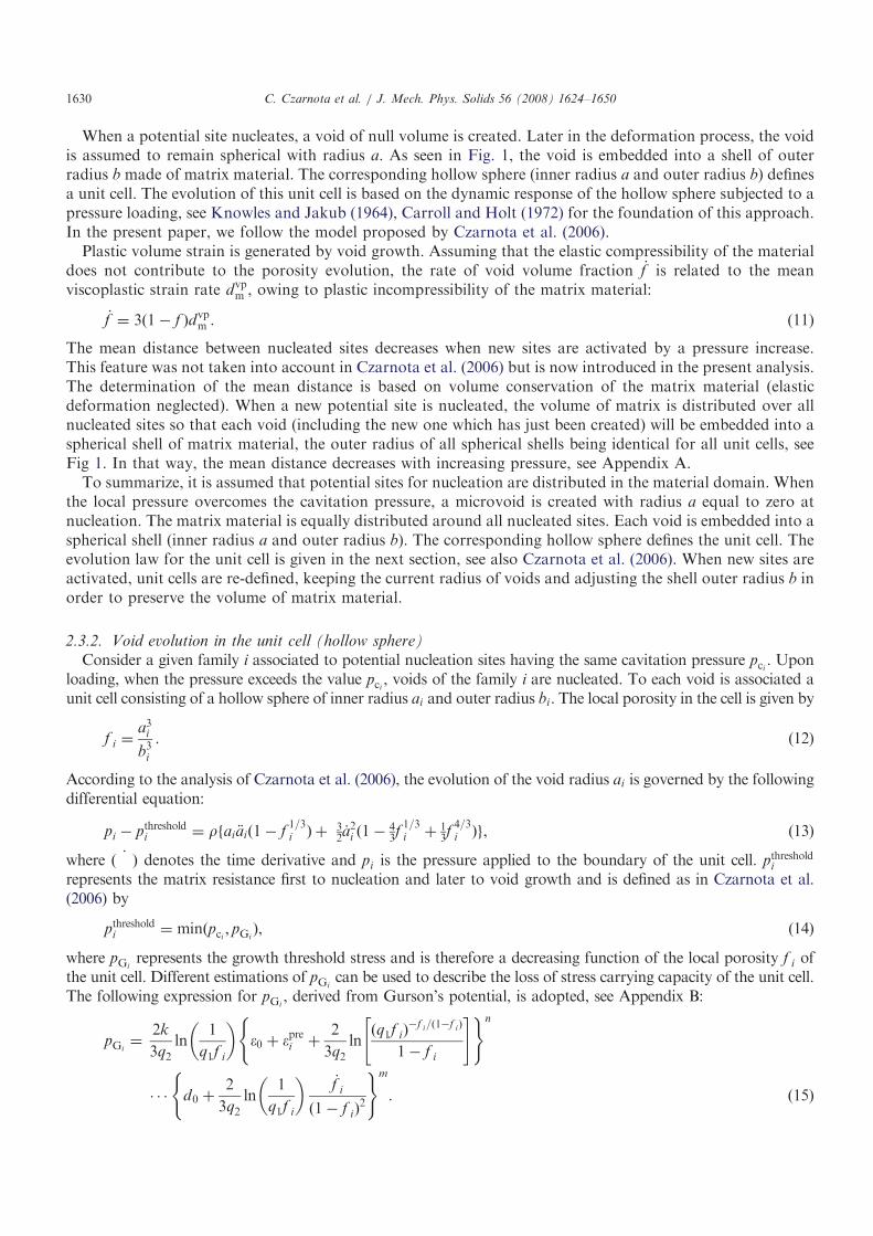
When a potential site nucleates, a void of null volume is created. Later in the deformation process, the void
is assumed to remain spherical with radius a. As seen in Fig. 1, the void is embedded into a shell of outer
radius b made of matrix material. The corresponding hollow sphere (inner radius a and outer radius b) defines
a unit cell. The evolution of this unit cell is based on the dynamic response of the hollow sphere subjected to a
pressure loading, see Knowles and Jakub (1964), Carroll and Holt (1972) for the foundation of this approach.
In the present paper, we follow the model proposed by Czarnota et al. (2006).
Plastic volume strain is generated by void growth. Assuming that the elastic compressibility of the material
does not contribute to the porosity evolution, the rate of void volume fraction _f is related to the mean
viscoplastic strain rate dvpm , owing to plastic incompressibility of the matrix material:
_f ¼ 3ð1ÿ f Þdvpm . (11)
The mean distance between nucleated sites decreases when new sites are activated by a pressure increase.
This feature was not taken into account in Czarnota et al. (2006) but is now introduced in the present analysis.
The determination of the mean distance is based on volume conservation of the matrix material (elastic
deformation neglected). When a new potential site is nucleated, the volume of matrix is distributed over all
nucleated sites so that each void (including the new one which has just been created) will be embedded into a
spherical shell of matrix material, the outer radius of all spherical shells being identical for all unit cells, see
Fig 1. In that way, the mean distance decreases with increasing pressure, see Appendix A.
To summarize, it is assumed that potential sites for nucleation are distributed in the material domain. When
the local pressure overcomes the cavitation pressure, a microvoid is created with radius a equal to zero at
nucleation. The matrix material is equally distributed around all nucleated sites. Each void is embedded into a
spherical shell (inner radius a and outer radius b). The corresponding hollow sphere defines the unit cell. The
evolution law for the unit cell is given in the next section, see also Czarnota et al. (2006). When new sites are
activated, unit cells are re-defined, keeping the current radius of voids and adjusting the shell outer radius b in
order to preserve the volume of matrix material.
2.3.2. Void evolution in the unit cell (hollow sphere)
Consider a given family i associated to potential nucleation sites having the same cavitation pressure pci . Upon
loading, when the pressure exceeds the value pci , voids of the family i are nucleated. To each void is associated a
unit cell consisting of a hollow sphere of inner radius ai and outer radius bi. The local porosity in the cell is given by
f i ¼a3i
b3i. (12)
According to the analysis of Czarnota et al. (2006), the evolution of the void radius ai is governed by the following
differential equation:
pi ÿ pthresholdi ¼ rfai €aið1ÿ f1=3i Þ þ 3
2_a2i ð1ÿ
43f1=3i þ 1
3f4=3i Þg, (13)
where _ð Þ denotes the time derivative and pi is the pressure applied to the boundary of the unit cell. pthresholdi
represents the matrix resistance first to nucleation and later to void growth and is defined as in Czarnota et al.
(2006) by
pthresholdi ¼ minðpci ; pGiÞ, (14)
where pGirepresents the growth threshold stress and is therefore a decreasing function of the local porosity f i of
the unit cell. Different estimations of pGican be used to describe the loss of stress carrying capacity of the unit cell.
The following expression for pGi, derived from Gurson’s potential, is adopted, see Appendix B:
pGi¼
2k
3q2ln
1
q1f i
� �
�0 þ �prei þ2
3q2ln
ðq1f iÞÿf i=ð1ÿf iÞ
1ÿ f i
" #( )n
� � � d0 þ2
3q2ln
1
q1f i
� �
_f i
ð1ÿ f iÞ2
( )m
. ð15Þ
ARTICLE IN PRESS
C. Czarnota et al. / J. Mech. Phys. Solids 56 (2008) 1624–16501630
�prei represents the equivalent plastic strain cumulated before the nucleation of the void i. In the present work,
q1 ¼ q2 ¼ 1. The evolution of the porosity f i is governed by plastic incompressibility of the matrix material within
the unit cell:
_f i ¼ 3f ið1ÿ f iÞ_ai
ai. (16)
During the deformation process, elastic unloading may occur and then the void growth will stop. Nevertheless, the
family i is considered as active, since the corresponding nucleation sites of this family has led to the occurrence of
microvoids with non-zero radius. The family i contributes to the overall porosity f.
2.3.3. Second level of homogenization
The material domain can be viewed as an assembly of unit cells: each unit cell corresponding to a hollow
sphere. Let us note the mean total strain rate and the overall pressure at the boundary of the material domain
by dm and p. At the local level inside the material domain, each unit cell with label i will face some pressure pi.
Different homogenization schemes can be used to link local quantities at the unit cell level to macroscopic
quantities defined at the remote boundary of the material domain. In the present contribution, two
homogenization schemes have been adopted named p-model or d-model.
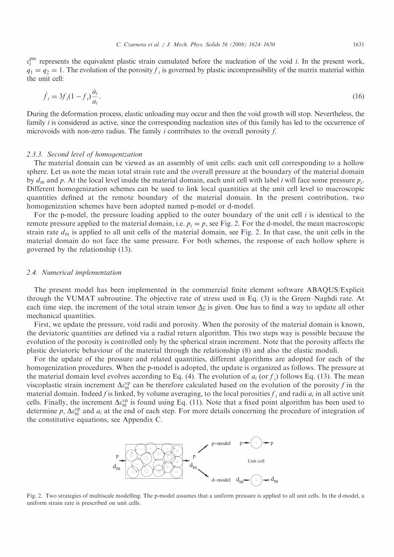
For the p-model, the pressure loading applied to the outer boundary of the unit cell i is identical to the
remote pressure applied to the material domain, i.e. pi ¼ p, see Fig. 2. For the d-model, the mean macroscopic
strain rate dm is applied to all unit cells of the material domain, see Fig. 2. In that case, the unit cells in the
material domain do not face the same pressure. For both schemes, the response of each hollow sphere is
governed by the relationship (13).
2.4. Numerical implementation
The present model has been implemented in the commercial finite element software ABAQUS/Explicit
through the VUMAT subroutine. The objective rate of stress used in Eq. (3) is the Green–Naghdi rate. At
each time step, the increment of the total strain tensor D� is given. One has to find a way to update all other
mechanical quantities.
First, we update the pressure, void radii and porosity. When the porosity of the material domain is known,
the deviatoric quantities are defined via a radial return algorithm. This two steps way is possible because the
evolution of the porosity is controlled only by the spherical strain increment. Note that the porosity affects the
plastic deviatoric behaviour of the material through the relationship (8) and also the elastic moduli.
For the update of the pressure and related quantities, different algorithms are adopted for each of the
homogenization procedures. When the p-model is adopted, the update is organized as follows. The pressure at
the material domain level evolves according to Eq. (4). The evolution of ai (or f i) follows Eq. (13). The mean
viscoplastic strain increment D�vpm can be therefore calculated based on the evolution of the porosity f in the
material domain. Indeed f is linked, by volume averaging, to the local porosities f i and radii ai in all active unit
cells. Finally, the increment D�vpm is found using Eq. (11). Note that a fixed point algorithm has been used to
determine p, D�vpm and ai at the end of each step. For more details concerning the procedure of integration of
the constitutive equations, see Appendix C.
ARTICLE IN PRESS
dmdm
p p
dmdm
Unit cell
..
..
.
...
..
...
...
pp
Fig. 2. Two strategies of multiscale modelling. The p-model assumes that a uniform pressure is applied to all unit cells. In the d-model, a
uniform strain rate is prescribed on unit cells.
C. Czarnota et al. / J. Mech. Phys. Solids 56 (2008) 1624–1650 1631

When the d-model is used, the pressure acting on the unit cell i is given by Eq. (4) :
_pi ¼ 3K ideim þ
_K i
K i
pi, (17)
where K i is the bulk modulus of the unit cell i given by Eq. (5). The new void radius ai is evaluated using Eqs.
(13) and (17). The pressure over the material domain is obtained by volume averaging over all potentially
active families: p ¼ hpii. More details concerning the numerical procedure is presented in Appendix D.
3. Results
3.1. Description of the tantalum behaviour
The material is a high purity grade tantalum. The parameters of Eq. (6) have been identified based on
compression tests carried out by Roy (2003) at different strain rates, up to a strain of 0.1. The coefficients a
and b adopted for Eq. (8) have been proposed by Eftis et al. (1991) with a ¼ 1=ðf cÞ0:5 and b ¼ 0:5. Roy (2003)
has observed that the coalescence at the end of the ductile fracture process in tantalum occurs by direct
impingement. This author has evaluated the critical volume fraction of voids based on observations of void
density in the spall plane: f c ¼ 0:3. The material is initially free of voids. The statistical information on
cavitation pressure of potential nucleation sites is provided by the Weibull law (10). The parameters, listed in
Table 2, are evaluated according to trends observed by Roy (2003). For instance, no void were nucleated when
the shock pressure was below 3:2� 0:2GPa. Thus, the value of p0c is set to 3GPa. So far, three parameters
remain to be determined: bw, Zw and N. These parameters are chosen in order to reproduce the experimental
particle velocity profile of the free surface obtained by Roy (2003). Only the results with a flyer thickness of
ef ¼ 3mm have been used. The number of potential nucleation sites per unit volume is set to
N ¼ 1:96� 1013mÿ3. The values of bw, Zw are given in Table 2. The probability density function W ðpcÞ
adopted in the work, presented in Fig. 3, has a large distribution of nucleation pressures. This choice is guided
by experimental data. From Roy (2003), the number of nucleated voids increases strongly with the shock
pressure. The maximum shock pressure in plate impact tests conducted by Roy (2003) was 30GPa. No
saturation of the number of voids is observed at 30GPa. To rationalize the fact that new voids can be
nucleated for shock pressures over 30GPa, a narrow distribution is not adequate for this tantalum. With the
adopted value of bw, Zw, the mean cavitation pressure is pc ¼ 48:4GPa. Such a value enables us to describe a
continuous nucleation process with no saturation of the number of voids up to large shock pressures.
ARTICLE IN PRESS
nucleation pressure (GPa)
dis
trib
uti
on o
f pote
nti
al n
ucl
eati
on s
ites
(1/G
Pa)
0 20 40 60 80 100 120 1400
0.005
0.01
0.015
0.02
Fig. 3. Weibull probability density law of the cavitation pressures with parameters given in Table 2.
C. Czarnota et al. / J. Mech. Phys. Solids 56 (2008) 1624–16501632

However, since we have simulated plate impact tests with moderate shock pressures (less than 10GPa), only
the shape of the density function for low nucleation pressures is really needed. The slope of the density
function for pressures close to p0c is a relevant parameter for the present modelling.
The continuous distribution of nucleation pressures is discretized. Thus, N f families of potential nucleation
sites are introduced. The probability of existence of nucleation sites with nucleation pressure pc4p0c þ 9sw is
negligible, with sw being the standard deviation of the Weibull probability density function. Therefore, the
interval ½p0c; p0c þ 9sw� is equally divided into N f subintervals of length Lc ¼ 9sw=N f . The family F i
corresponds to the group of sites with nucleation pressure belonging to the interval ½p0c þ ði ÿ 1ÞLc; p0c þ iLc�.
The associated appearance frequency is Pri ¼R p0cþiLc
p0cþðiÿ1ÞLcW ðpcÞdpc. The nucleation pressure of all sites
belonging to the family F i is set to pci ¼ p0c þ ði ÿ 1=2ÞLc. No effect of the discretization scheme has been
observed, for the Weibull distribution adopted in the present work, when Lc is below 0.2GPa.
3.2. Uniaxial deformation
Before simulating complex experiments, as plate impact tests, where wave propagation has a strong effect
on the structural response, the model developed in Section 2 has been first investigated in uniaxial
deformation. This loading path is representative of the deformation state during impact loading when the
lateral extent of the plates is at least height times the thickness, see Meyers and Aimone (1983). The applied
strain rate d is
d ¼ D11
1 0 0
0 0 0
0 0 0
2
6
4
3
7
5. (18)
In the elastic regime, Eq. (3) simplifies into the classical Hooke’s law. The stress components are related to the
logarithmic longitudinal strain �11 ¼ D11t by
s11 ¼ ðK þ 43GÞ�11; s22 ¼ ðK ÿ 2
3GÞ�11; p ¼ K�11. (19)
The yield condition is satisfied when
js11 ÿ s22j ¼ syield (20)
with syield ¼ ð1ÿ af bÞsyðdeq; �eqÞ, see Eq. (8). Therefore, during plastic yielding, the longitudinal stress s11 is
related to p by
s11 ¼ pþ 23syield with p40 ðtensionÞ, ð21Þ
s11 ¼ pÿ 23syield with po0 ðcompressionÞ. ð22Þ
In the following, the evolution of the pressure p is analysed. The longitudinal stress s11 is obtained from p by
an appropriate translation of � 23syield during elastic–plastic loading.
The pressure within the material is presented in Fig. 4 for an overall imposed uniaxial straining. Numerical
tests have been conducted for three different strain rates. The results in Fig. 4 have been obtained by means of
the two different homogenization schemes introduced above, uniform pressure (p-model) or uniform strain
rate (d-model) applied on all unit cells. The initial stage of the deformation process is not affected by the
adopted scheme. The same maximum pressure is found. This is obviously related to the material homogeneity
before microvoiding. Differences are observed after the first oscillation. At the beginning of the loading, the
pressure evolves in a linear manner; the slope corresponding to the bulk elastic modulus. In uniaxial
deformation, when the material is free of voids, the pressure response is purely elastic since no volume plastic
strain can be generated. Therefore, one can easily show that, even if deviatoric plasticity is triggered, one
obtains the following pressure evolution:
p ¼ K0�11 ¼ K0D11t. (23)
When the pressure p overcomes p0c, voids are nucleated. Due to micro-inertia effects, void growth is very
limited, the volume plastic strain being still negligible. Thus the pressure evolution remains almost elastic even
when p overcomes p0c and can be approximated by Eq. (23) with good accuracy up to the maximum. It is
ARTICLE IN PRESS
C. Czarnota et al. / J. Mech. Phys. Solids 56 (2008) 1624–1650 1633
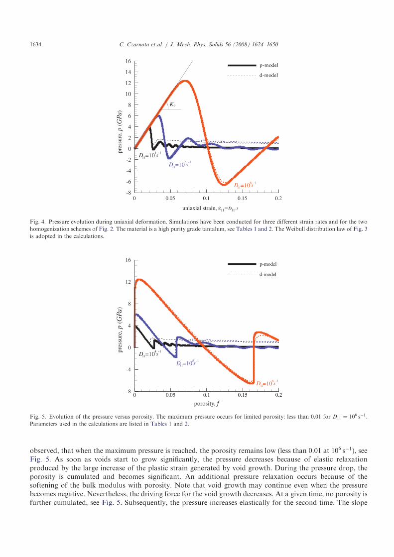
observed, that when the maximum pressure is reached, the porosity remains low (less than 0.01 at 106 sÿ1), see
Fig. 5. As soon as voids start to grow significantly, the pressure decreases because of elastic relaxation
produced by the large increase of the plastic strain generated by void growth. During the pressure drop, the
porosity is cumulated and becomes significant. An additional pressure relaxation occurs because of the
softening of the bulk modulus with porosity. Note that void growth may continue even when the pressure
becomes negative. Nevertheless, the driving force for the void growth decreases. At a given time, no porosity is
further cumulated, see Fig. 5. Subsequently, the pressure increases elastically for the second time. The slope
ARTICLE IN PRESS
uniaxial strain,
pre
ssu
re, p
(G
Pa
)
0 0.05 0.1 0.15 0.2-8
-6
-4
-2
0
2
4
6
8
10
12
14
16
ε =
d-model
p-model
D .t11
=10 s6 -1
D11=10 s
4 -1
D11=10 s
5 -1
11
11D
Ko
Fig. 4. Pressure evolution during uniaxial deformation. Simulations have been conducted for three different strain rates and for the two
homogenization schemes of Fig. 2. The material is a high purity grade tantalum, see Tables 1 and 2. The Weibull distribution law of Fig. 3
is adopted in the calculations.
porosity, f
pre
ssu
re, p
(G
Pa
)
0 0.05 0.1 0.15 0.2-8
-4
0
4
8
12
16
D =10 s6 -1
D11=10 s
4 -1
D11=10 s
5 -1
11
d-model
p-model
Fig. 5. Evolution of the pressure versus porosity. The maximum pressure occurs for limited porosity: less than 0.01 for D11 ¼ 106 sÿ1.
Parameters used in the calculations are listed in Tables 1 and 2.
C. Czarnota et al. / J. Mech. Phys. Solids 56 (2008) 1624–16501634
defining the pressurization rate is lower than K0 because of the softening of the elastic properties by porosity,
see Eq. (5). The slope is smaller for larger strain rates, indicating that a larger porosity is cumulated during the
pressure decrease at large strain rate. For D11 ¼ 104 sÿ1, the value of f during the second increase of the
pressure is 0:027. For D11 ¼ 105 sÿ1, f ¼ 0:059 and for D11 ¼ 106 sÿ1, f ¼ 0:165, see Fig. 5.
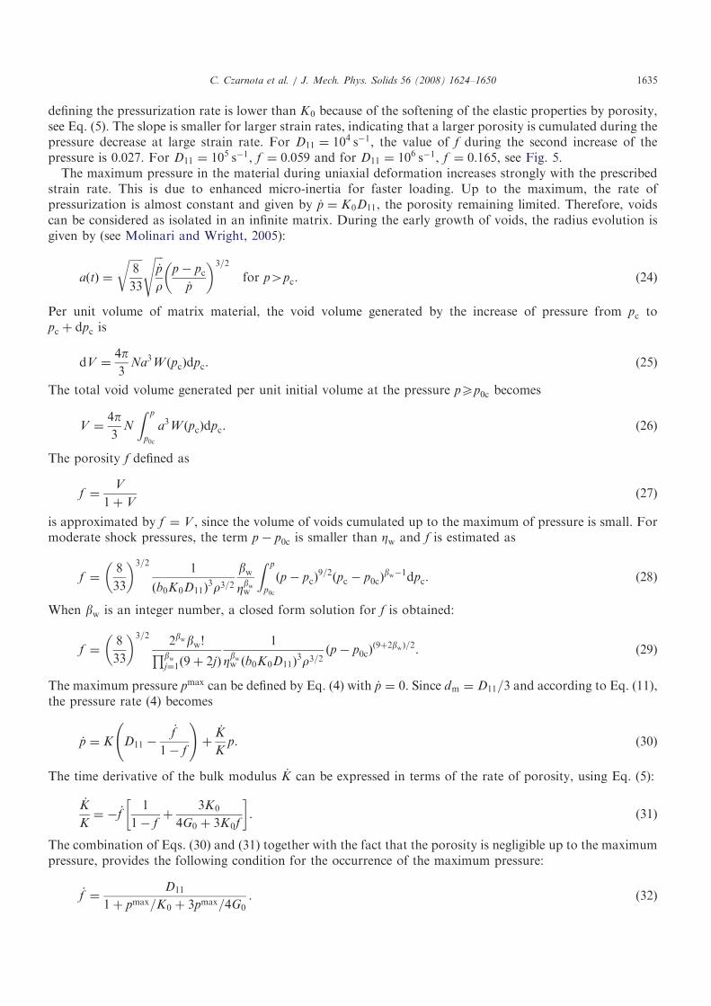
The maximum pressure in the material during uniaxial deformation increases strongly with the prescribed
strain rate. This is due to enhanced micro-inertia for faster loading. Up to the maximum, the rate of
pressurization is almost constant and given by _p ¼ K0D11, the porosity remaining limited. Therefore, voids
can be considered as isolated in an infinite matrix. During the early growth of voids, the radius evolution is
given by (see Molinari and Wright, 2005):
aðtÞ ¼
ffiffiffiffiffi
8
33
r
ffiffiffi
_p
r
s
pÿ pc_p
� �3=2
for p4pc. (24)
Per unit volume of matrix material, the void volume generated by the increase of pressure from pc to
pc þ dpc is
dV ¼4p
3Na3W ðpcÞdpc. (25)
The total void volume generated per unit initial volume at the pressure pXp0c becomes
V ¼4p
3N
Z p
p0c
a3W ðpcÞdpc. (26)
The porosity f defined as
f ¼V
1þ V(27)
is approximated by f ¼ V , since the volume of voids cumulated up to the maximum of pressure is small. For
moderate shock pressures, the term pÿ p0c is smaller than Zw and f is estimated as
f ¼8
33
� �3=21
ðb0K0D11Þ3r3=2
bw
Zbww
Z p
p0c
ðpÿ pcÞ9=2ðpc ÿ p0cÞ
bwÿ1dpc. (28)
When bw is an integer number, a closed form solution for f is obtained:
f ¼8
33
� �3=22bwbw!
Qbwj¼1ð9þ 2jÞ
1
Zbww ðb0K0D11Þ
3r3=2ðpÿ p0cÞ
ð9þ2bwÞ=2. (29)
The maximum pressure pmax can be defined by Eq. (4) with _p ¼ 0. Since dm ¼ D11=3 and according to Eq. (11),
the pressure rate (4) becomes
_p ¼ K D11 ÿ_f
1ÿ f
!
þ_K
Kp. (30)
The time derivative of the bulk modulus _K can be expressed in terms of the rate of porosity, using Eq. (5):
_K
K¼ ÿ _f
1
1ÿ fþ
3K0
4G0 þ 3K0f
� �
. (31)
The combination of Eqs. (30) and (31) together with the fact that the porosity is negligible up to the maximum
pressure, provides the following condition for the occurrence of the maximum pressure:
_f ¼D11
1þ pmax=K0 þ 3pmax=4G0
. (32)
ARTICLE IN PRESS
C. Czarnota et al. / J. Mech. Phys. Solids 56 (2008) 1624–1650 1635
By time derivative of Eq. (29) and using Eqs. (23) and (32), the following implicit equation is derived for pmax:
pmax ¼ p0c þ333=2
Qbwÿ1j¼0 ð9þ 2jÞ
83=2 � 9 � 2bwÿ1bw!
!2=ð7þ2bwÞ
Zbww b30r
3=2K20D
311
1þ pmax=K0 þ 3pmax=4G0
!2=ð7þ2bwÞ
. (33)
For moderate shock pressures, pmax is smaller than the value of the elastic moduli, and the last equation can be
simplified to provide a closed form expression for pmax:
pmax ¼ p0c þ333=2
Qbwÿ1j¼0 ð9þ 2jÞ
83=2 � 9 � 2bwÿ1bw!
!2=ð7þ2bwÞ
ðZbww b30r3=2K2
0D311Þ
2=ð7þ2bwÞ. (34)
Note that, a closed form solution exists also when all sites have the same nucleation pressure p0c:
pmax ¼ p0c þ1331
384
� �1=7
ðb60r3K4
0D611Þ
1=7. (35)
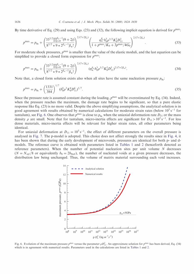
Since the pressure rate is assumed constant during the loading, pmax will be overestimated by Eq. (34). Indeed,
when the pressure reaches the maximum, the damage rate begins to be significant, so that a pure elastic
response like Eq. (23) is no more valid. Despite the above simplifying assumptions, the analytical solution is in
good agreement with results obtained by numerical calculations for moderate strain rates (below 105 sÿ1 for
tantalum), see Fig. 6. One observes that pmax is close to p0c when the uniaxial deformation rate D11 or the mass
density r are small. Note that for tantalum, micro-inertia effects are significant for D114103 sÿ1. For less
dense materials, micro-inertia effects will be relevant for higher strain rates, all other parameters being
identical.
For uniaxial deformation at D11 ¼ 105 sÿ1, the effect of different parameters on the overall pressure is
analysed in Fig. 7. The p-model is adopted. This choice does not affect strongly the results since in Fig. 4, it
has been shown that during the early development of microvoids, pressures are identical for both p- and d-
models. The reference curve is obtained with parameters listed in Tables 1 and 2 (henceforth denoted as
reference parameters). When the number of potential nucleation sites per unit volume N decreases
(N ¼ Nref=8 or equivalently b0 ¼ 2b0ref ), the number of nucleated voids at a given pressure decreases, the
distribution law being unchanged. Thus, the volume of matrix material surrounding each void increases.
ARTICLE IN PRESS
max
imum
pre
ssure
, p
ma
x (G
Pa
)
108
109
1010
1011
1012
1013
1014
1015
1016
1017
0
2
4
6
8
10
12
14
poc=3GPa
ρ-2
kg.m .s11
Analytical solution
Numerical results
D ( )2 -3
Fig. 6. Evolution of the maximum pressure pmax versus the parameter rD211. An approximate solution for pmax has been derived, Eq. (34)
which is in agreement with numerical results. Parameters used in the calculations are listed in Tables 1 and 2.
C. Czarnota et al. / J. Mech. Phys. Solids 56 (2008) 1624–16501636

Micro-inertia is therefore enhanced and induces an increase of pmax, see Fig. 7. The parameters of the Weibull
law influence also the pressure evolution in the material. The effect of p0c is clear, since delaying the nucleation
of voids will generate a larger pressure in the material. A smaller value of Zw modifies the shape of the Weibull
distribution (see Fig. 8), leading to a larger number of nucleated voids for a prescribed pressure. Therefore, the
volume of matrix surrounding each void is lowered, and so is micro-inertia. The maximum pressure is then
decreased. An increase of bw induces the nucleation of fewer voids, for moderate pressure, as compared to the
reference value bwrefof Table 2, see Fig. 8. Thus, a larger maximum pressure is predicted, see Fig. 7.
3.3. Plate impact experiments
The model has been implemented in the explicit finite element software ABAQUS/Explicit using the user-
subroutine VUMAT. The predictions of the proposed model are compared to experiments of Roy (2003) in
tantalum. A cylindrical flyer plate of thickness ef (value given later) and diameter 50mm collides a target plate
of thickness et ¼ 4:95mm. Both plates are made of tantalum. The contact between the flyer and the target is
ARTICLE IN PRESS
time, t (µs)
pre
ssu
re, p
(G
Pa
)
0 0.25 0.5 0.75 1-4
-2
0
2
4
6
8
10
5 -1s=10
b =2b00 ref
η=η /1.5
reference
oc
ref
β=β 1.5ref
p =p +2GPaoc
ref
D11
x
Fig. 7. Effect of the number of potential nucleation sites per unit volume (N ¼ 1=ðð4p=3Þb30Þ) and of the Weibull parameters on the
pressure evolution. The loading rate is D11 ¼ 105 sÿ1. The reference curve is obtained with parameters listed in Tables 1 and 2.
Table 1
Material parameters representative of a high purity grade tantalum
K0 (GPa) G0 (GPa) r ðkg=m3Þ k (IS) e0 n d0 ðsÿ1Þ m f c
200 68.3 16600 528� 106 0.055 0.155 10ÿ4 0.058 0.30
Table 2
Parameters used to describe the statistical distribution of nucleation pressure in the tantalum material. The corresponding probability
density function, given by Eq. (10), is represented in Fig. 3
p0c (GPa) bw Zw (GPa) b0 ðmmÞ
3 2 51.19 23
C. Czarnota et al. / J. Mech. Phys. Solids 56 (2008) 1624–1650 1637

governed by a Coulomb friction law with a friction coefficient of 0.3 and takes place over the whole surface,
see Fig. 9. The velocity of the flyer, before impact is V impact whereas the target plate is at rest. The density of
potential nucleation sites in the whole material is assumed homogeneous. Therefore, an axisymmetric
approach is adopted. The mechanical analysis is performed on a two-dimensional section of the flyer and
target plates. Four-node bilinear elements with reduced integration (named CAX4R) have been adopted.
Velocity profiles at the target free surface are obtained with simulations and are compared to experimental
measurements. In our approach, those profiles correspond to the velocity of the material point P located on
the rear face along the axisymmetric axis, see Fig. 9. The numerical analysis enables to capture information
such as pressure, strain rate and porosity evolution inside the target during tests. Such data cannot be obtained
during experiments. Therefore, a clear and complete picture of the plate impact test can be proposed.
ARTICLE IN PRESS
0 5 10 150
0.002
0.004
0.006
0.008
0.01
nucleation pressure (GPa)
dis
trib
uti
on
of
po
ten
tial
nu
clea
tio
n s
ites
(1
/GP
a)
0 20 40 60 80 100 1400
0.005
0.01
0.015
0.02
0.025
0.03 η=ηref
/1.5
reference
β=βref
x1.5
poc=pocref+2GPa
120
Fig. 8. Various Weibull distributions of the nucleation pressure. The reference curve is obtained with values defined in Table 2.
Vimpact
axis of revolution
CAX4Rmeasurement of thefree-surface velocity
V impact
50 mm
3 mm
4.95 mm
P
Fig. 9. Configuration of the plate impact experiments. An axisymmetric approach is adopted. Only a two-dimensional cross-section is
meshed. Four-node bilinear elements with reduced integration have been used for the simulations. The point P on the target indicates the
node where the free-surface velocity profile is captured.
C. Czarnota et al. / J. Mech. Phys. Solids 56 (2008) 1624–16501638
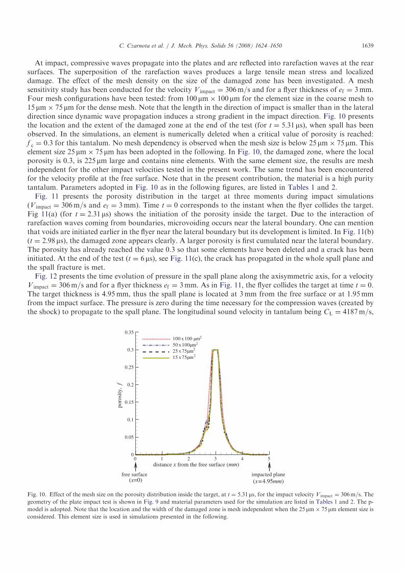
At impact, compressive waves propagate into the plates and are reflected into rarefaction waves at the rear
surfaces. The superposition of the rarefaction waves produces a large tensile mean stress and localized
damage. The effect of the mesh density on the size of the damaged zone has been investigated. A mesh
sensitivity study has been conducted for the velocity V impact ¼ 306m=s and for a flyer thickness of ef ¼ 3mm.
Four mesh configurations have been tested: from 100mm� 100mm for the element size in the coarse mesh to
15mm� 75mm for the dense mesh. Note that the length in the direction of impact is smaller than in the lateral
direction since dynamic wave propagation induces a strong gradient in the impact direction. Fig. 10 presents
the location and the extent of the damaged zone at the end of the test (for t ¼ 5:31ms), when spall has been
observed. In the simulations, an element is numerically deleted when a critical value of porosity is reached:
f c ¼ 0:3 for this tantalum. No mesh dependency is observed when the mesh size is below 25mm� 75 mm. This
element size 25mm� 75mm has been adopted in the following. In Fig. 10, the damaged zone, where the local
porosity is 0.3, is 225mm large and contains nine elements. With the same element size, the results are mesh
independent for the other impact velocities tested in the present work. The same trend has been encountered
for the velocity profile at the free surface. Note that in the present contribution, the material is a high purity
tantalum. Parameters adopted in Fig. 10 as in the following figures, are listed in Tables 1 and 2.
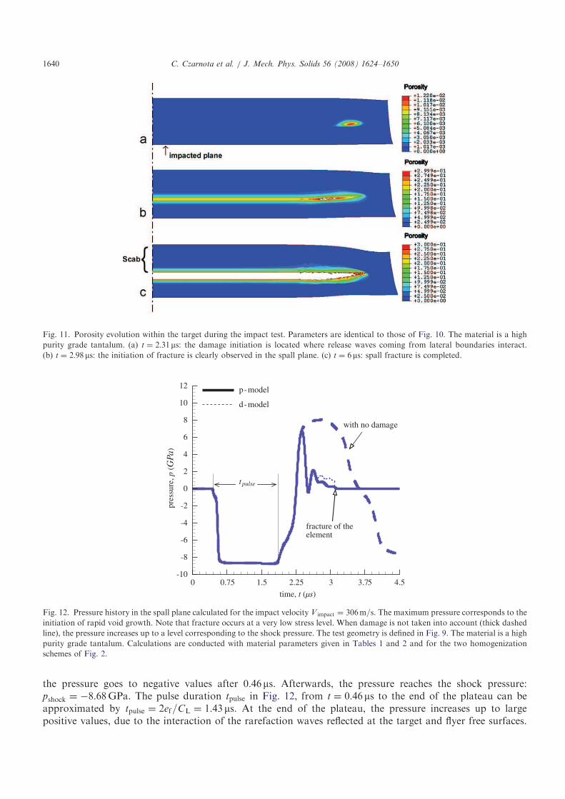
Fig. 11 presents the porosity distribution in the target at three moments during impact simulations
(V impact ¼ 306m=s and ef ¼ 3mm). Time t ¼ 0 corresponds to the instant when the flyer collides the target.
Fig 11(a) (for t ¼ 2:31ms) shows the initiation of the porosity inside the target. Due to the interaction of
rarefaction waves coming from boundaries, microvoiding occurs near the lateral boundary. One can mention
that voids are initiated earlier in the flyer near the lateral boundary but its development is limited. In Fig. 11(b)
(t ¼ 2:98ms), the damaged zone appears clearly. A larger porosity is first cumulated near the lateral boundary.
The porosity has already reached the value 0.3 so that some elements have been deleted and a crack has been
initiated. At the end of the test (t ¼ 6ms), see Fig. 11(c), the crack has propagated in the whole spall plane and
the spall fracture is met.
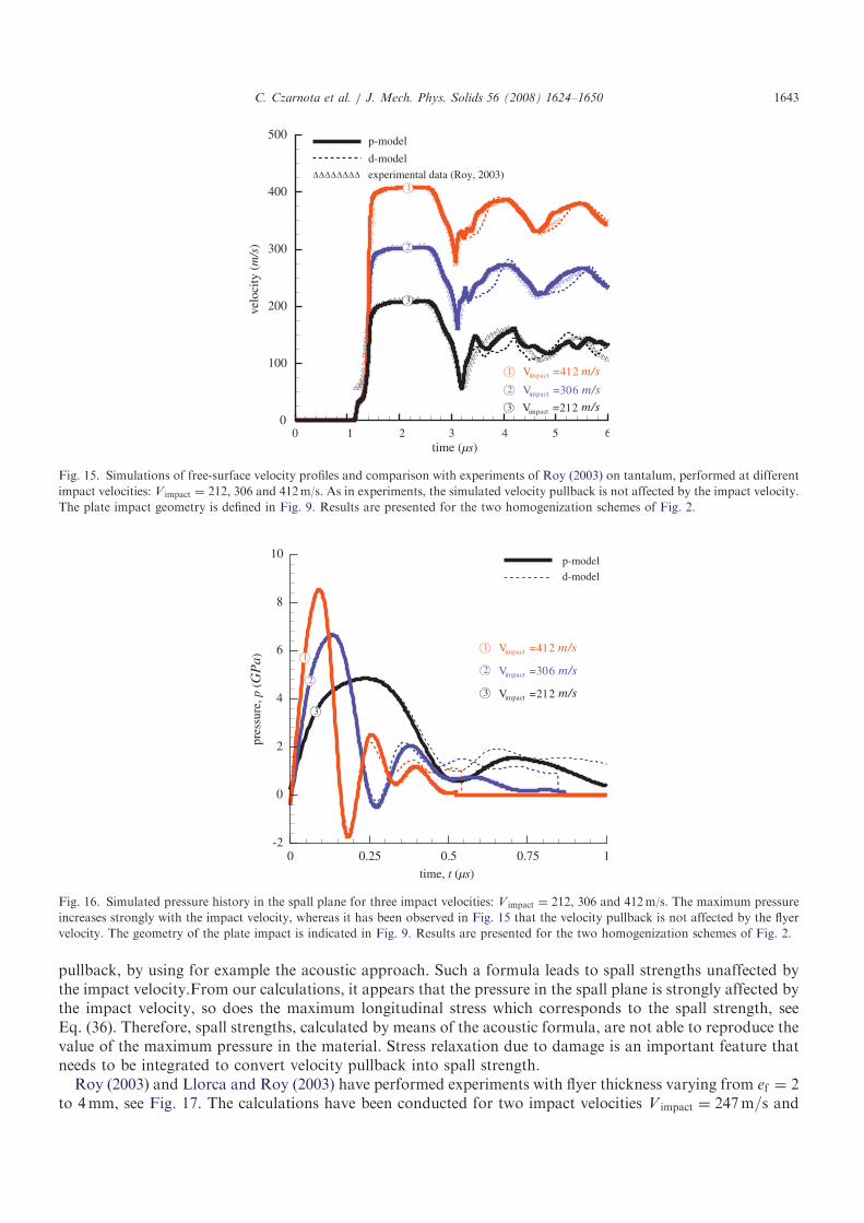
Fig. 12 presents the time evolution of pressure in the spall plane along the axisymmetric axis, for a velocity
V impact ¼ 306m=s and for a flyer thickness ef ¼ 3mm. As in Fig. 11, the flyer collides the target at time t ¼ 0.
The target thickness is 4.95mm, thus the spall plane is located at 3mm from the free surface or at 1.95mm
from the impact surface. The pressure is zero during the time necessary for the compression waves (created by
the shock) to propagate to the spall plane. The longitudinal sound velocity in tantalum being CL ¼ 4187m=s,
ARTICLE IN PRESS
distance x from the free surface (mm)
po
rosi
ty,
f
0 50
0.05
0.1
0.15
0.2
0.25
0.3
0.35
impacted planefree surface
(x=4.95mm)(x=0)
100 100 µm
50 100µm
25 75µm
15 75µm
2
2
2
2x
x
x
x
1 2 3 4
Fig. 10. Effect of the mesh size on the porosity distribution inside the target, at t ¼ 5:31ms, for the impact velocity V impact ¼ 306m=s. The
geometry of the plate impact test is shown in Fig. 9 and material parameters used for the simulation are listed in Tables 1 and 2. The p-
model is adopted. Note that the location and the width of the damaged zone is mesh independent when the 25mm� 75mm element size is
considered. This element size is used in simulations presented in the following.
C. Czarnota et al. / J. Mech. Phys. Solids 56 (2008) 1624–1650 1639
the pressure goes to negative values after 0:46ms. Afterwards, the pressure reaches the shock pressure:
pshock ¼ ÿ8:68GPa. The pulse duration tpulse in Fig. 12, from t ¼ 0:46ms to the end of the plateau can be
approximated by tpulse ¼ 2ef=CL ¼ 1:43ms. At the end of the plateau, the pressure increases up to large
positive values, due to the interaction of the rarefaction waves reflected at the target and flyer free surfaces.
ARTICLE IN PRESS
Fig. 11. Porosity evolution within the target during the impact test. Parameters are identical to those of Fig. 10. The material is a high
purity grade tantalum. (a) t ¼ 2:31ms: the damage initiation is located where release waves coming from lateral boundaries interact.
(b) t ¼ 2:98ms: the initiation of fracture is clearly observed in the spall plane. (c) t ¼ 6ms: spall fracture is completed.
time, t (µs)
pre
ssure
, p (
GP
a)
0 0.75 1.5 2.25 3.75 4.5-10
-8
-6
-4
-2
0
2
4
6
8
10
12
d-model
with no damage
p-model
fracture of theelement
3
pulset
Fig. 12. Pressure history in the spall plane calculated for the impact velocity V impact ¼ 306m=s. The maximum pressure corresponds to the
initiation of rapid void growth. Note that fracture occurs at a very low stress level. When damage is not taken into account (thick dashed
line), the pressure increases up to a level corresponding to the shock pressure. The test geometry is defined in Fig. 9. The material is a high
purity grade tantalum. Calculations are conducted with material parameters given in Tables 1 and 2 and for the two homogenization
schemes of Fig. 2.
C. Czarnota et al. / J. Mech. Phys. Solids 56 (2008) 1624–16501640

As mentioned previously, the pressure relaxation is produced by the rapid development of void growth.
Predictions based on the two homogenization schemes are reported in Fig. 12. The pressure responses in the
spall plane are similar up to the second peak. A porosity of 0.3 is encountered in the material domain at nearly
the same time for the p- and d- models. When damage is disregarded (thick dashed line), it is observed that the
tensile pressure reaches a higher value. Due to plasticity, dissipation and wave dispersion during propagation,
the shock amplitude is limited to 8GPa, whereas in compression the pressure was ÿ8:68GPa. In plate impact
experiments, the use of the longitudinal stress is more common. The maximum tensile longitudinal stress (in
the impact direction) smax11 is related to the maximum pressure pmax by
smax11 ¼ pmax þ 2
3syield, (36)
where smax11 represents the incipient spall strength of the material, see Antoun et al. (2003). The numerical
simulation provides the following value for the spall strength: smax11 ¼ 7:11GPa with pmax ¼ 6:65GPa.
The simulation of the particle velocity at the free surface is shown in Fig. 13 for the two homogenization
schemes. The velocity remains zero during 1:18 ms, due to wave propagation of the pulse. When the
compression waves arrive at the free surface and reflect into tension waves, the velocity of the particle reaches
first a velocity VHEL corresponding to the Hugoniot elastic limit. Later with the arrival of the elastic–plastic
waves, the velocity of the material point becomes V impact. The duration of the pulse corresponds to the
duration of the negative pressure pulse in Fig. 12 with a time delay due to wave propagation. The pressure
drop in the spall plane due to the incipient void growth induces the pullback signal on the free surface.
Without any damage (thick dashed line), the pullback signal does not exist. The velocity pullback is not
relevant of the fracture, at least for ductile materials, see Antoun et al. (2003). The period of the velocity
oscillation (after the pullback) can be related to the thickness of the scab. From calculations, the period is
almost tpulse. As a consequence, the thickness of the scab is close to ef , distance from the free surface to the
spall plane, Antoun et al. (2003). In Fig. 13, the velocity profiles are not affected by the prescribed
homogenization scheme, up to the pullback signal. A better agreement with experiments is obtained with
p-model for the late evolution of the free-surface velocity (subsequent velocity oscillations). The spall fracture
is observed inside the target when a critical porosity of 0.3 is reached. It is difficult to observe directly this
event on the velocity profile. From calculations, the time to fracture has been estimated and is presented in
Fig. 13 using an arrow.
ARTICLE IN PRESS
time (µs)
vel
oci
ty (
m/s
)
0 60
100
200
300
400
spall fracture
p-model
experimental data (Roy, 2003)
d-model
∇∇∇∇∇∇∇∇
with no damage
pullbackvelocity
pulset
1 2 3 4 5
Fig. 13. Simulations of free-surface velocity profiles and comparison with experimental data of Roy (2003) on tantalum. The impact
velocity is V impact ¼ 306m=s. The test geometry is defined in Fig. 9. The maximum pressure observed in Fig. 12 induces the velocity
pullback on the free-surface velocity profile. The thick dashed line corresponds to the case where damage is not accounted for.
Calculations are conducted for the two homogenization schemes of Fig. 2.
C. Czarnota et al. / J. Mech. Phys. Solids 56 (2008) 1624–1650 1641

In Fig. 13, calculations are carried out with material parameters listed in Tables 1 and 2. The hardening
behaviour has been identified on compression tests up to a strain of 0.1. For such a strain level, the
temperature increase generated during the deformation is limited. Therefore, parameters of Table 1 adopted
for the present work, are able to describe the isothermal response of tantalum. Recently, Rittel et al. (2007)
have performed dynamic testing, on a different pure grade tantalum. They carried out shear testing so that
they were able to reach large plastic strain (up to 0.5). As a result, they found that their tantalum has a little
strain hardening. The reduction of the strain hardening coefficient at high strain rate is due to adiabatic
heating. Based on these observations, the effect of temperature can be indirectly estimated in the calculations,
by adopting a lower value of the strain hardening coefficient. For that purpose, plate impact simulations have
been conducted with different material parameters (k ¼ 385� 106 IS, n ¼ 0, other parameters involved in
Eq. (6) being kept constant). k has been adjusted to preserve the same flow stress level for the tantalum.
Predicted free-surface velocities, presented in Fig. 14, are almost unchanged. As a consequence, it can be
concluded that the effect of thermal softening can be neglected for moderate shock pressures.
The effect of the impact velocity has been investigated in Fig. 15. The thickness of the flyer is ef ¼ 3mm and
the material parameters are unchanged and listed in Tables 1 and 2. Simulated velocities are compared to
experiments of Roy (2003) and Llorca and Roy (2003). The results are accurate, when the p-model is
prescribed, and remains in good agreement with the d-model. Fig. 16 presents the pressure in the spall plane
for the three impact velocities used for Fig. 15. In Fig. 16, time t ¼ 0 corresponds to the moment where the
pressure becomes positive. The simulations confirm that the material is subjected to uniaxial deformation in
the spall plane. As the impact velocity increases, the loading rate increases. But the rate of pressurization and
the total strain rate are not constant up to the maximum of pressure. The calculated slope at the origin
indicates that the initial rate of pressurization varies from _p ¼ 46GPa=ms for V impact ¼ 212m=s to _p ¼
132GPa=ms at V impact ¼ 412m=s. A higher rate of pressurization enhances micro-inertia effects and leads to a
larger maximum pressure: pmax ¼ 4:85GPa at V impact ¼ 212m=s and pmax ¼ 8:55GPa at V impact ¼ 412m=s.The maximum pressure is larger when the flyer collides the target at higher velocity, but the amplitude of the
velocity pullback is almost identical for the three velocities. This result agrees with experiments made on many
materials showing that increasing the shock amplitude does not lead to a change in the pullback magnitude,
see Antoun et al. (2003) for aluminium and titanium alloy, Roy (2003) and Llorca and Roy (2003) for
tantalum, see Fig. 15. In the literature, the longitudinal spall strength is linked to the amplitude of the
ARTICLE IN PRESS
time (µs)
vel
oci
ty (
m/s
)
0 60
100
200
300
400
zoom
reference (n=0.155, k=528.106 IS)
no strain hardening (n=0, k=385.106 IS)
1 2 3 4 5
Fig. 14. Predicted free-surface velocities for a plate impact test at moderate shock pressure: impact velocity V impact ¼ 306m=s and
thickness ef ¼ 3mm. The reference curve (solid line) is obtained with parameters of Table 1. The hardening coefficient is n ¼ 0:155. Forthe second curve (dashed line), the material response presents no strain hardening n ¼ 0 due to adiabatic heating. The parameter k has
been adjusted to keep the same flow stress level of the tantalum.
C. Czarnota et al. / J. Mech. Phys. Solids 56 (2008) 1624–16501642
pullback, by using for example the acoustic approach. Such a formula leads to spall strengths unaffected by
the impact velocity.From our calculations, it appears that the pressure in the spall plane is strongly affected by
the impact velocity, so does the maximum longitudinal stress which corresponds to the spall strength, see
Eq. (36). Therefore, spall strengths, calculated by means of the acoustic formula, are not able to reproduce the
value of the maximum pressure in the material. Stress relaxation due to damage is an important feature that
needs to be integrated to convert velocity pullback into spall strength.
Roy (2003) and Llorca and Roy (2003) have performed experiments with flyer thickness varying from ef ¼ 2
to 4mm, see Fig. 17. The calculations have been conducted for two impact velocities V impact ¼ 247m=s and
ARTICLE IN PRESS
time (µs)
vel
oci
ty (
m/s
)
0 60
100
200
300
400
500
experimental data (Roy, 2003)
d-model
∇∇∇∇∇∇∇∇
V =212impact
V =412impact
V =306impact
1
3
2
m/s
m/s
m/s
1
3
2
1 2 3 4 5
p-model
Fig. 15. Simulations of free-surface velocity profiles and comparison with experiments of Roy (2003) on tantalum, performed at different
impact velocities: V impact ¼ 212, 306 and 412m/s. As in experiments, the simulated velocity pullback is not affected by the impact velocity.
The plate impact geometry is defined in Fig. 9. Results are presented for the two homogenization schemes of Fig. 2.
time, t (µs)
pre
ssu
re,
p (
GP
a)
0 0.25 0.5 0.75 1-2
0
2
4
6
8
10
1
3
2
V =212impact
V =412impact
V =306impact
1
3
2
m/s
m/s
m/s
p-model
d-model
Fig. 16. Simulated pressure history in the spall plane for three impact velocities: V impact ¼ 212, 306 and 412m/s. The maximum pressure
increases strongly with the impact velocity, whereas it has been observed in Fig. 15 that the velocity pullback is not affected by the flyer
velocity. The geometry of the plate impact is indicated in Fig. 9. Results are presented for the two homogenization schemes of Fig. 2.
C. Czarnota et al. / J. Mech. Phys. Solids 56 (2008) 1624–1650 1643

V impact ’ 306m=s. Material parameters are unchanged and given in Tables 1 and 2. Note that parameters of
the Weibull law were calibrated based on experiments with a flyer thickness ef ¼ 3mm. The predictions based
on the two homogenization schemes are also presented. A close agreement with experiments is obtained for
the three thicknesses, whatever the adopted schemes. Nevertheless, as already mentioned, more accurate
results are given by the p-model. The duration of the pulse, from t ¼ 1:18ms to the end of the plateau increases
with the flyer thickness since it is proportional to the thickness of the flyer and approximated by 2ef=CL where
CL is the longitudinal elastic sound velocity. Considering tests carried out at V impact ’ 306m=s, it is observedthat the magnitude of the velocity pullback is larger for thinner flyer. Since the same impact velocity is
prescribed to the flyer, the magnitude of the maximum pressure in the spall plane is identical for the three tests
(results not presented here). The thickness of the flyer affects the location of the spall plane. When the flyer
thickness is below half of the target thickness, the spall plane is located near the free surface. On the contrary,
when the flyer thickness is over half of the target thickness, the spall plane is located near the impact surface.
Note that when the target thickness is twice the flyer’s one, the spall plane is exactly located in the middle of
the target. As maximum pressures are unaffected by the flyer thickness, the larger relaxation of tension waves
observed for a thicker flyer can be attributed to the longer propagation distance towards the free surface. The
larger damping generates a smaller pullback, as observed in Fig. 17. As in Fig. 13, the velocity oscillations
observed after pullback have periods linked to the scab extent when the spallation has been observed or to the
location of the damaged zone when the fracture is not complete. As expected, the duration of the oscillation
period for the three tests provides a value of the scab thickness close to the flyer extent ef and corresponds to
the location of the damaged zone or spall plane in the target.
To clarify the relative influence of the different physical concepts included in the proposed model, some
calculations have been done with simplified versions of the p-model, in which some phenomena (and their
mathematical descriptions) have been neglected. The corresponding free-surface velocities are presented in
Fig. 18. The reference free-surface velocity corresponds to a plate impact test at V impact ¼ 306m=s for a flyer
thickness ef ¼ 3mm. When the dependence of porosity on the yield stress is neglected (the a value in Eq. (8) is
set to zero), no effect is expected and observed on the velocity pullback. Indeed, the velocity pullback begins
with the pressure release observed in the spall plane at the initiation of microvoiding for which f � 0. The
effect of f on the yield function (8) is nevertheless necessary to capture accurately the velocity level during the
oscillations (after the pullback signal).
ARTICLE IN PRESS
time (µs)
vel
oci
ty (
m/s
)
0 1 2 3 4 5 60
100
200
300
400
V =303impact
13 2
1
2
4
e =4i m/smm
V =247impacte =2i m/smm
V =306impacte =3i m/smm
d-model
∇∇∇∇∇∇∇∇
3 V =307impacte =2i m/smm
4
p-model
experimental data (Roy, 2003)
Fig. 17. Simulated free-surface velocity profiles compared to experiments of Roy (2003) on tantalum. The target thickness is 4.95mm. The
flyer thickness is varied in the range (2–4)mm. Simulations are conducted for two impact velocities: V impact ¼ 247m=s and
V impact ’ 306m=s. Note that the velocity pullback is depending on the flyer thickness. Material parameters are given in Tables 1 and
2. Results are presented for the two homogenization schemes of Fig. 2.
C. Czarnota et al. / J. Mech. Phys. Solids 56 (2008) 1624–16501644

Fig. 18 clearly shows the necessity of accounting for the porosity dependence (at the unit cell level) of the
stress carrying capacity of the matrix pthresholdi , Eq. (14). When this term remains equal to the cavitation
pressure pci during all the deformation process, it is observed that the velocity pullback is not well predicted. In
addition, the velocity oscillations after the pullback are not reproduced. From calculations, the porosity level
cumulated at the end of the experiment is 0:18, value below f c. So, for pthresholdi ¼ pci , no spall fracture is met in
the simulations whereas in experiments, the fracture is clearly apparent with a well defined scab.
Our modelling is based on two major physical concepts: micro-inertia and continuous nucleation of voids.
Fig. 18 illustrates clearly that without those keypoints, the velocity profile cannot be simulated with good
accuracy.
When the mass density used in Eq. (13) is reduced to a low value r ¼ 0:3 kg=m3, micro-inertia effects almost
disappear. Note that the mass density is not modified in the equation of motion, so that the macroscopic
inertia is not changed. When the pressure reaches the lowest cavitation pressure p0c in the spall plane, the
porosity is immediately cumulated since micro-inertia effects are too weak to refrain void growth. Thus, the
pressure peak in the spall plane is underestimated, and so is the velocity pullback. In addition, without micro-
inertia, the velocity level during the subsequent oscillations are overestimated. Note that p0c is not an
adjustable parameter since it has been determined from experiments.
The importance of continuous nucleation of voids is illustrated also in Fig. 18. If all nucleation sites have
the same cavitation pressure p0c, it is observed that the magnitude of the velocity pullback can be reproduced
for V impact ¼ 306m=s by increasing the characteristic length b0 (or equivalently by decreasing the number of
potential sites N). But the velocity oscillations are not well captured. In addition, the evolution of the velocity
pullback for different impact velocities cannot be reproduced.
4. Conclusion
In this paper, a model of void nucleation and growth is proposed and used to characterize dynamic damage
in metals subjected to extreme loading conditions. The material is elastic–viscoplastic and initially void free
(but the presence of initial voids can be as well considered). Microvoids are generated at potential nucleation
sites when the nucleation pressure is overcome by the local pressure loading. Owing to microstructural
ARTICLE IN PRESS
time, t (µs)
vel
oci
ty (
m/s
)
2 3 4 5 650
150
250
350
1
b =237µm0
in Eq.(13)threshold
pci
=p4
3
5
1
2
2
3
4
5
for all unit cells ,
α=0 in Eq.(8)
without microinertia (ρ∼0 in Eq.(13))
reference
ip =pci
oc
Fig. 18. Effect of different parameters on the predicted free-surface velocity. The following conditions are considered: target thickness
4.95mm, flyer thickness 3mm, impact velocity: V impact ¼ 306m=s. Simulations are based on the p-model. Material parameters are given in
Tables 1 and 2.
C. Czarnota et al. / J. Mech. Phys. Solids 56 (2008) 1624–1650 1645

heterogeneities and to the presence of residual stresses, the nucleation pressure varies from site to site.
A Weibull probability density function is adopted to describe the fluctuation of nucleation pressures within the
material. When the local pressure increases, more voids are nucleated. The growth of a void is described by
using a hollow sphere model where micro-inertia effects are accounted for. The matrix weakening due to void
growth is also included.
To simulate plate impact experiments, our dynamic damage model has been implemented in ABAQUS/
Explicit. All the model parameters have been identified from independent experiments, except for three
parameters characterizing the statistical distribution of the nucleation pressures. These parameters have been
deduced from impact experiments at three different velocities with the same flyer size. The model is then used
as a predictive tool to simulate experiments with various flyer sizes and velocities. The free-surface velocity
profiles measured by Roy (2003) and Llorca and Roy (2003) are reproduced with excellent accuracy for all
experimental configurations.
These simulations bring a new insight into the mechanism of spalling and into the interpretation of
experimental measurements. From observations, it is generally deduced in the literature (acoustic assumption)
that for aluminium, titanium and tantalum, the maximum stress sustained by the material (spall stress) is not
affected by the impact velocity. In our model, the maximum stress in the spall plane strongly increases with the
impact velocity. Nevertheless, the velocity pullback at the target free surface is shown, as in experiments, to be
independent of the impact velocity for a given flyer geometry. In addition, the effect of the flyer size on the
velocity pullback is exactly captured. These results bring some confidence on the physical mechanisms
introduced in the present dynamic damage model. The stabilizing effect of micro-inertia is of particular
importance, as it controls the level of the maximum stress and the development of damage during stress
relaxation in the spall plane.
Appendix A. Evolution of the mean distance between active sites
In the present approach, the mean spacing between nucleated sites decreases when the pressure and the number
of nucleated voids increase. Different methods can be selected to describe the mean spacing evolution during the
loading. In the present paper, we have adopted the following concept: when new voids are nucleated, the total
volume of the matrix material is distributed so as to have the same external radii for all unit cells.
Let us consider the initial volume of the material domain Vdomain ¼ Ns=N ¼ ð4=3ÞpNsb30. Ns represents the
total number of potential sites and b0 is the characteristic length defined in Eq. (9). As the pressure overcomes
pc1 , NsPr1 voids are nucleated. Assuming that potential sites in the first family are randomly distributed in the
material domain, the mean spacing b between nucleated sites (only the first family being activated), is given by
NsPr1
4
3pb3 ¼ Vdomain ) b ¼
b0
P1=3r1
. (A.1)
Consider now that J families are active defining J unit cells. All unit cells of the family i have the same internal
and external radii ai and bi. At a given time, the pressure loading increases up to reach pcJþ1. Therefore, NsPrJþ1
voids nucleate, with zero void radius. For the considered time, we affect to all unit cells the same outer radius
b, keeping all current radii ai unchanged. Owing to volume preserving of the matrix material, the new mean
distance between voids satisfies:
Vdomain ¼X
J
i¼1
4
3pNsPri ðb
3 ÿ a3i Þ þ4
3pNsPrJþ1
b3. (A.2)
This leads to the following definition of the external radius b of all unit cells when the ðJ þ 1Þth family
nucleates:
b ¼b30 þ
PJi¼1Pria
3i
PJþ1i¼1 Pri
" #1=3
. (A.3)
If nucleation sites have the same cavitation pressure pc, the initial outer radius of the unit cell is b ¼ b0.
ARTICLE IN PRESS
C. Czarnota et al. / J. Mech. Phys. Solids 56 (2008) 1624–16501646
Note that with the present formalism, the local porosity in each unit cell is not continuous. Nevertheless, the
porosity of the material domain remains continuous. In addition, the rearrangement of the matrix material
over all nucleated sites, when a new family becomes active, induces a change in the total kinetic energy of the
whole representative volume element. The variation exists only during the nucleation stage. It has been
checked that the loss in kinetic energy is limited. The cumulated loss of kinetic energy at the end of the
nucleation stage represents less than 100th (10ÿ2) of the total kinetic energy in the representative volume
element.
Appendix B. Definition of the threshold pressure pGi
In pure hydrostatic loading, the potential developed first by Gurson (1977) and modified by Tvergaard
(1981) is
O ¼ 2q1f cosh3q22
Sm
s
� �
ÿ ð1þ ðq1f Þ2Þ ¼ 0, (B.1)
where Sm designates the macroscopic pressure (acting at the boundary of the hollow sphere). Therefore, Sm
represents exactly the threshold pressure PG, present in Eq. (14). s denotes an average strength of the matrix
material. One may refer to Duva (1986) for a precise definition of s related to particular matrix behaviour.
The matrix behaviour is governed by Eq. (6):
s ¼ kðd0 þ dÞmð�0 þ �Þn (B.2)
where d is a measure of the average microscopic strain rate in the matrix and � ¼R
d dt is an average
microscopic plastic strain.
From Eq. (B.1), the effective stress s becomes
s ¼3
2q2jSmj
1
lnð1=q1f Þ. (B.3)
For hydrostatic loading, neglecting elasticity, the equivalence of plastic work rate results in
3jSmjjDmj ¼ ð1ÿ f Þsd. (B.4)
The mean macroscopic plastic strain rate Dm is linked to the rate of porosity by
Dm ¼_f
3ð1ÿ f Þ. (B.5)
Combining Eqs. (B.3)–(B.4), the mean microscopic strain rate d is given by
d ¼2
3q2ln
1
q1f
� �
_f
ð1ÿ f Þ2. (B.6)
The average microscopic strain � is obtained by time integration of d:
� ¼2
3q2
lnð1=q1f Þ
1ÿ fþ ln
f
1ÿ f
� �� �
þ Cte. (B.7)
The constant term is found using the initial condition. When the void nucleates, the matrix has already faced a
microscopic plastic strain, noted �pre. Therefore, one obtains
� ¼ �pre þ2
3q2ln
ðq1f Þÿf =ð1ÿf Þ
1ÿ f
" #
. (B.8)
ARTICLE IN PRESS
C. Czarnota et al. / J. Mech. Phys. Solids 56 (2008) 1624–1650 1647

Finally, using Eqs. (B.2), (B.3), (B.6) and (B.8), the threshold pressure is obtained:
PG ¼2k
3q2ln
1
q1f
� �
�0 þ �pre þ2
3q2ln
ðq1f Þÿf =ð1ÿf Þ
ð1ÿ f Þ
" #( )n
� d0 þ2
3q2ln
1
q1f
� �
_f
ð1ÿ f Þ2
( )m
. (B.9)
Appendix C. Update with the p-model
In Abaqus, as in most Finite Element software, the total mean strain increment D�m is given at the beginning
of each calculation step. All quantities are defined at the beginning of the time increment (time t). Let us note
pðtÞ, f ðtÞ, f iðtÞ, aiðtÞ the pressure, porosities and void radius of the ith family at time t. Knowing D�m, one hasto update all other mechanical fields (pressure, void radii, porosity, mean viscoplastic strain increment). In this
Appendix, the p-model is adopted for the determination of the void radius in each unit cell in the material
domain. Therefore, for each active site, pi ¼ p.
The pressure rate is defined by Eq. (4). Thus, the pressure increment pðtþ DtÞ ÿ pðtÞ can be related to the
increment of elastic strain D�em:
pðtþ DtÞ ÿ pðtÞ ¼Kðf ðtþ DtÞÞ ÿ Kðf ðtÞÞ
Kðf ðtÞÞpðtÞ þ 3Kðf ðtÞÞD�em, (C.1)
where Dt is the time increment and f ðtþ DtÞ the porosity of the material domain at the end of the step time.
The total strain increment is the sum of the elastic and viscoplastic part, see Eq. (1). Thus the pressure
pðtþ DtÞ can be expressed in terms of total and viscoplastic strain increments:
pðtþ DtÞ ¼ pðtÞKðf ðtþ DtÞÞ
Kðf ðtÞÞþ 3Kðf ðtÞÞðD�m ÿ D�vpm Þ. (C.2)
The mean viscoplastic strain increment D�vpm is unknown. This quantity is related to the porosity in the
material domain which depends on the void radii in all active families. But void evolution is strongly
depending upon pressure, see Eq. (13). Thus, difficulties arise because pressure, void radii and inelastic strain
increment are strongly coupled. A fixed point algorithm is adopted to solve this coupling.
First, a guess for D�vpm is proposed. An elastic prediction may be adopted where D�vpm ¼ 0. Therefore,
according to Eq. (C.2), a guess of the pressure at the end of the step pðtþ DtÞ is obtained. Then, the void radius
ai of all active families is evaluated, using Eq. (13):
pðtþ DtÞ ÿ pthresholdi ðf iðtþ DtÞÞ ¼ r aiðtþ DtÞ €aiðtþ DtÞð1ÿ f1=3i ðtþ DtÞÞ
�
þ3
2_a2i ðtþ DtÞ 1ÿ
4
3f1=3i ðtþ DtÞ þ
1
3f4=3i ðtþ DtÞ
� ��
, ðC:3Þ
where
f iðtþ DtÞ ¼a3i ðtþ DtÞ
b3i ðtþ DtÞ. (C.4)
The external radius of the unit cell associated to the ith family is obtained owing to plastic incompressibility of
the matrix material inside the ith unit cell: b3i ðtþ DtÞ ÿ a3i ðtþ DtÞ ¼ b3i ðtÞ ÿ a3i ðtÞ. The time derivatives of ai are
defined using Newmark equations (with g ¼ 12and b ¼ 1
4):
_aiðtþ DtÞ ¼ 2aiðtþ DtÞ ÿ aiðtÞ
Dt
� �
ÿ _aiðtÞ,
€aiðtþ DtÞ ¼ 4aiðtþ DtÞ ÿ aiðtÞ
Dt2ÿ
_aiðtÞ
Dt
� �
ÿ €aiðtÞ. ðC:5Þ
ARTICLE IN PRESS
C. Czarnota et al. / J. Mech. Phys. Solids 56 (2008) 1624–16501648

The estimation of the radius aiðtþ DtÞ is derived from a single-variable algebraic equation. The porosity of the
material domain f ðtþ DtÞ is obtained by volume averaging over all active families:
f ðtþ DtÞ ¼
PJi¼1Pria
3i ðtþ DtÞ
PJi¼1Prib
3i ðtþ DtÞ
, (C.6)
where J is the number of active families at the beginning of the time increment. From the relationship (11), a
new guess for the mean viscoplastic strain increment D�vpm ðtþ DtÞ is derived:
D�vpm ðtþ DtÞ ¼f ðtþ DtÞ ÿ f ðtÞ
3ð1ÿ f ðtÞÞ. (C.7)
A new iteration is carried out. The procedure is continued until convergence on the mean viscoplastic strain
increment and on pressure. In the calculation, a relative precision of 10ÿ5 between two subsequent guesses (for
both pressure and viscoplastic strain increment) is adopted as convergence criterium.
Appendix D. Update with the d-model
In the d-model, for each active site, the total volume strain increment acting on the boundary D�mi is given by
D�mi ¼ D�m. Owing to Eq. (17), the pressure over a given unit cell is obtained in a similar way as for Eq. (C.2):
piðtþ DtÞ ¼ piðtÞK iðf iðtþ DtÞÞ
K iðf iðtÞÞþ 3K iðf iðtÞÞðD�m ÿ D�vpmiÞ (D.1)
with Dt is the time step. The mean strain increment D�m is known. The viscoplastic volume strain increment D�vpmi is
sought. The void radius ai is governed by Eq. (13):
piðtþ DtÞ ÿ pthresholdi ðf iðtþ DtÞÞ ¼ r aiðtþ DtÞ €aiðtþ DtÞð1ÿ f1=3i ðtþ DtÞÞ
�
þ3
2_a2i ðtþ DtÞ 1ÿ
4
3f1=3i ðtþ DtÞ þ
1
3f4=3i ðtþ DtÞ
� ��
ðD:2Þ
f iðtþ DtÞ and biðtþ DtÞ are defined as in Appendix C. A predictor–corrector scheme based on the Newmark
equations is applied to compute the quantities aiðtþ DtÞ, biðtþ DtÞ, f iðtþ DtÞ and D�vpmi for all potentially active
families (their number is denoted J). Finally, the pressure over the material domain is obtained by volume
averaging over all potentially active families:
pðtþ DtÞ ¼
PJi¼1 Prib
3i ðtþ DtÞpiðtþ DtÞ
PJi¼1 Prib
3i ðtþ DtÞ
. (D.3)
References
Adam, L., 2003. Modelisation du comportement thermo-elasto-viscoplastique des metaux soumis a grandes deformations. Application au
formage superplastique. Ph.D. Thesis, Faculte des sciences appliquees, Universite de Liege, Belgium.
Antoun, T., Seaman, L., Curran, D.R., Kanel, G., Razorenov, S., Utkin, A., 2003. Spall Fracture. Springer, Berlin.
Ball, J.M., 1982. Discontinuous equilibrium solutions and cavitation in nonlinear elasticity. Philos. Trans. R. Soc. London Ser. A 306, 557–611.
Becker, R., 2002. Ring fragmentation predictions using the Gurson model with material stability conditions as failure criteria. Int. J. Solids
Struct. 39, 3555–3580.
Boidin, X., Chevrier, P., Klepaczko, J., Sabar, H., 2006. Identification of damage mechanism and validation of a fracture model based on
mesoscale approach in spalling of titanium alloy. Int. J. Solids Struct. 43, 4595–4615.
Bontaz-Carion, J., Pellegrini, Y.P., 2006. X-ray microtomography analysis of dynamic damage in tantalum. Adv. Eng. Mater. 8, 480–486.
Campagne, L., Daridon, L., Ahzi, S., 2005. A physically based model for dynamic failure in ductile metals. Mech. Mater. 37, 869–886.
Carroll, M.M., Holt, A.C., 1972. Static and dynamic pore-collapse relations for ductile porous materials. J. Appl. Phys. 43, 1626–1636.
Chen, D., Yu, Y., Yin, Z., Wang, H., Liu, G., 2005. On the validity of the traditional measurement of spall strength. Int. J. Impact Eng.
31, 811–824.
Cochran, S., Banner, D., 1977. Spall studies in uranium. J. Appl. Phys. 48, 2729–2737.
Cortes, R., 1992. The growth of microvoids under intense dynamic loading. Int. J. Solids Struct. 29, 1339–1350.
Curran, D.R., Seaman, L., Shockey, D.A., 1987. Dynamic Failure of Solids. Physics Reports. Elsevier, Amsterdam, pp. 253–388.
ARTICLE IN PRESS
C. Czarnota et al. / J. Mech. Phys. Solids 56 (2008) 1624–1650 1649

Czarnota, C., Mercier, S., Molinari, A., 2006. Modelling of nucleation and void growth in dynamic pressure loading, application to spall
test on tantalum. Int. J. Fract. 141, 177–194.
Duva, J.M., 1986. A constitutive description of nonlinear materials containing voids. Mech. Mater. 5, 137–144.
Eftis, J., Nemes, J.A., 1991. Evolution equation for the void volume growth rate in a viscoplastic-damage constitutive model. Int. J.
Plasticity 7, 275–293.
Eftis, J., Nemes, J.A., Randles, P., 1991. Viscoplastic analysis of plate-impact spallation. Int. J. Plasticity 7, 15–39.
Eftis, J., Carrasco, C., Osegueda, R.A., 2003. A constitutive-microdamage model to simulate hypervelocity projectile-target impact,
material damage and fracture. Int. J. Plasticity 19, 1321–1354.
Feng, J., Jinq, F., Zhang, G., 1997. Dynamic ductile fragmentation and damage function model. J. Appl. Phys. 81, 2575–2578.
Gurson, A.L., 1977. Continuum theory of ductile rupture by void nucleation and growth: part I—yield criteria and flow rules for porous
ductile media. J. Eng. Mater. Technol. 99, 2–15.
Hill, R., 1950. The Mathematical Theory of Plasticity. Oxford University Press, Oxford.
Horgan, C.O., Polignone, D.A., 1995. Cavitation in nonlinearly elastic solids: a review. Appl. Mech. Rev. 48, 471–485.
Huang, Y., 1991. Accurate dilatation rates for spherical voids in triaxial stress fields. J. Appl. Mech. 58, 1084–1086.
Huang, Y., Hutchinson, J.W., Tvergaard, V., 1991. Cavitation instabilities in elastic–plastic solids. J. Mech. Phys. Solids 39, 223–241.
Ikkurthi, V.R., Chaturvedi, S., 2004. Use of different damage models for simulating impact-driven spallation in metal plates. Int. J. Impact
Eng. 30, 275–301.
Johnson, J.N., 1981. Dynamic fracture and spallation in ductile solids. J. Appl. Phys. 52, 2812–2825.
Kanel, G., Razorenov, S., Bogatch, A., Utkin, A., Grady, D., 1997. Simulation of spall fracture of aluminium and magnesium over a wide
range of load duration and temperature. Int. J. Impact Eng. 20, 467–478.
Knowles, J., Jakub, M., 1964. Finite dynamic deformations of an incompressible elastic medium containing a spherical cavity. Arch. Rat.
Mech. Anal. 18, 367–378.
Leblond, J., Roy, G., 2000. A model for dynamic ductile behavior applicable for arbitrary triaxialities. C.R. Acad. Sci. II B 328, 381–386.
Lee, B.J., Mear, M.E., 1994. Studies of the growth and the collapse of voids in viscous solids. J. Eng. Mater. Technol. 116, 348–358.
Lin, Z., Lingcang, C., Yinglei, L., Jianxiang, P., Fuqian, J., Dongquan, C., 2004. Simplified model for prediction of dynamic damage and
fracture of ductile materials. Int. J. Solids Struct. 41, 7063–7074.
Llorca, F., Roy, G., 2003. Metallurgical investigation of dynamic damage in tantalum. In: 13th APS Topical Conference on Shock
Compression of Condensed Matter. APS, Portland, OR, USA.
Mackenzie, J., 1958. The elastic constants of a solid containing spherical holes. Proc. Phys. Soc. London 63B, 2–11.
McClintock, F.A., 1968. A criterion for ductile fracture by the growth of holes. J. Appl. Mech. 35, 363–371.
Meyers, M.A., Aimone, C.T., 1983. Dynamic fracture (spalling) of metals. Prog. Mater. Sci. 28, 1–96.
Molinari, A., Mercier, S., 2001. Micromechanical modelling of porous materials under dynamic loading. J. Mech. Phys. Solids 49, 1497–1516.
Molinari, A., Wright, T.W., 2005. A physical model for nucleation and early growth of voids in ductile materials under dynamic loading.
J. Mech. Phys. Solids 53, 1476–1504.
Ortiz, M., Molinari, A., 1992. Effect of strain hardening and rate sensitivity on the dynamic growth of a void in a plastic material. J. Appl.
Mech. 114, 48–53.
Perzyna, P., 1963. The constitutive equations for rate sensitive plastic materials. Q. Appl. Math. 20, 321–332.
Perzyna, P., 1986. Internal state variable description of dynamic fracture of ductile solids. Int. J. Solids Struct. 22, 797–818.
Rajendran, A., Dietenberger, M., Grove, D., 1989. A void-growth based failure model to describe spallation. J. Appl. Phys. 65, 1521–1527.
Rice, J.R., Tracey, D.M., 1969. On the ductile enlargement of voids in triaxial stress fields. J. Mech. Phys. Solids 17, 201–217.
Rittel, D., Bhattacharyya, A., Poon, B., Zhao, J., Ravichandran, G., 2007. Thermomechanical characterization of pure polycrystalline
tantalum. Mater. Sci. Eng. A 447, 65–70.
Roy, G., 2003. Vers une modelisation approfondie de l’endommagement ductile dynamique. Investigation experimentale d’une nuance de
tantale et developpements theoriques. Ph.D. Thesis, Ecole Nationale Superieure de Mecanique et d’Aeronautique, Universite de
Poitiers, France.
Seaman, L., Curran, D., Shockey, D., 1976. Computational models for ductile and brittle fracture. J. Appl. Phys. 47, 4814–4826.
Steinberg, D., Sharp, R., 1981. Interpretation of shock-wave data for beryllium and uranium with an elastic–viscoplastic constitutive
model. J. Appl. Phys. 52, 5072–5088.
Suffis, A., 2004. Developpement d’un modele d’endommagement a taux de croissance controle pour la simulation robuste de ruptures sous
impacts. Ph.D. Thesis, Institut National des Sciences Appliquees, Lyon, France.
Tong, W., Ravichandran, G., 1995. Inertial effects on void growth in porous viscoplastic materials. Trans. ASME J. Appl. Mech. 62, 633–639.
Tvergaard, V., 1981. Influence of voids on shear bands instabilities under plane strain conditions. Int. J. Fract. 17, 389–407.
Tvergaard, V., Huang, Y., Hutchinson, J.W., 1992. Cavitation instabilities in a power hardening elastic–plastic solid. Eur. J. Mech. A
Solids 11, 215–231.
Wang, Z.P., Jiang, Q., 1997. A yield criterion for porous ductile media at high strain rate. J. Appl. Mech. 64, 503–509.
Weinberg, K., Mota, A., Ortiz, M., 2006. A variational constitutive model for porous metal plasticity. Comput. Mech. 37, 142–152.
Wright, T.W., Ramesh, K.T., Molinari, A., 2005. Status statistical modeling for damage from nucleation and growth of voids. In: 14th
APS Topical Conference on Shock Compression of Condensed Matter. APS, Baltimore, MD, USA.
Wu, X.Y., Ramesh, K.T., Wright, T.W., 2003. The dynamic growth of a single void in a viscoplastic material under transient hydrostatic
loading. J. Mech. Phys. Solids 51, 1–26.
Zurek, A., Thissell, W., Johnson, J., Tonks, D., Hixson, R., 1996. Micromechanics of spall and damage in tantalum. J. Mater. Process.
Technol. 60, 261–267.
ARTICLE IN PRESS
C. Czarnota et al. / J. Mech. Phys. Solids 56 (2008) 1624–16501650