Embed Size (px)
Citation preview
6-24 ENGINEERING PRINCIPLES AND PRACTICES for Retro�tting Flood-Prone Residential Structures
6 CASE STUDIES
6.2 Case Study #2: Residential Retrofit in Coastal A Zone Using Elevation or Acquisition
is case study exercise examines the retro"t of a residential building in a coastal #oodplain by means of elevation or acquisition. Details are provided in the subsections that follow.
6.2.1 Description of Property
Abe and Bea Chester 1234 Bay Street, Norfolk, VA 12345
Abe and Bea Chester built their home in the 1960s before #ood maps were developed for the area. e one-story, wood-frame structure does not have a basement. ey live on Bay Street, close to the beach, in Norfolk, VA. Although they live outside of Zone V, they are still in the SFHA (Zone A) and would like to protect their home from #ooding. ey are not interested in moving the house itself, but they may be willing to move out of the neighborhood if they can get money to purchase another house. Because they live in Zone A and are subject to coastal #ooding, they are interested in elevation on an open foundation. e local #oodplain ordinance prohibits elevation on "ll. e e$ective BFE is 4 feet above the "rst #oor elevation.
e Chesters indicated they would like to pursue retro"tting options that would allow them to obtain a reduced NFIP #ood insurance rate. If possible, the Chesters would like to apply for HMA grant assistance.
6.2.2 Structure Information
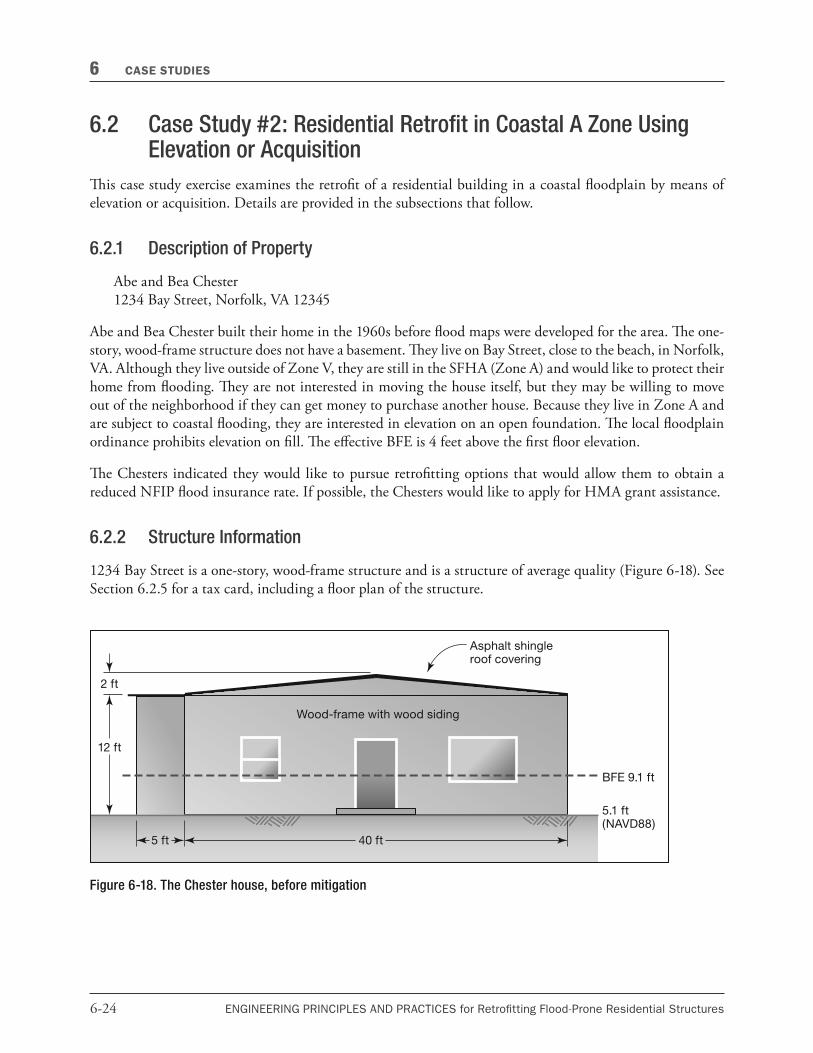
1234 Bay Street is a one-story, wood-frame structure and is a structure of average quality (Figure 6-18). See Section 6.2.5 for a tax card, including a #oor plan of the structure.
Figure 6-18. The Chester house, before mitigation

6-25ENGINEERING PRINCIPLES AND PRACTICES for Retro�tting Flood-Prone Residential Structures
CASE STUDIES 6
Other structure information includes:
4 Footprint:
4 1,025 square feet (see section 6.2.5)
4 Foundation:
4 6-inch-thick concrete slab on a 2-foot-wide x 1-foot-thick concrete wall footer
4 Structure:
4 First #oor elevation of 5.1 feet NAVD88, measured from the top of the lowest "nished #oor
4 Wood-frame structure
4 Wood siding
4 Wood-frame interior walls with gypsum board sheathing
4 Roof:
4 Gable roof without overhangs over main structure (35-foot x 25-foot plan area)
4 Flat roof without overhangs over side areas (two 5-foot x 15-foot areas)
4 Asphalt shingle roof covering over entire roof
4 Interior:
4 Wood stud interior walls with gypsum board sheathing
4 Hardwood #oor coverings
Plot
e Chesters’ plot is essentially #at and relatively small. e entire plot is in the SFHA. e ground elevation is between 5.1 feet and 5.3 feet (NAVD88) over the entire plot. e site soils are primarily a mixture of silty sand and gravel (Soil Type SM).
Building Assessment
An updated tax card is included at the end of this case study as an alternate source of the building replacement value as well as to verify the building square footage data.
Additionally, an engineer’s estimate is that the Chesters’ home has a building replacement value of approximately $80 per square foot, based on popular cost estimating guides.

6-26 ENGINEERING PRINCIPLES AND PRACTICES for Retro�tting Flood-Prone Residential Structures
6 CASE STUDIES
Flood Hazard Data
e local #oodplain management ordinance applies to all structures in the SFHA. Elevation on "ll is strictly prohibited, and a 1-foot freeboard is required for all new construction and substantial improvements. e #ood map (FIRMette) is included in Section 6.2.5 to document the #ood hazard data used below.
e applicable excerpts from the FIS show the #ood elevations and the BFE for the existing structure and are included in Section 6.2.5. Table 6-4 shows the stillwater elevations and BFE of the property.
Table 6-4. Stillwater Elevations for the Chester House
Stillwater Elevations (ft)
BFE 10-year 50-year 100-year 500-year
9.1 5.5 6.9 7.6 8.9
Note: All topographic maps and flood hazard data reference NAVD88.
A licensed surveyor "lled out the elevation certi"cate, which references NAVD88 and is included at the end of this case study.
e base #ood #ow velocity is assumed to be 3.0 feet per second.
6.2.3 Retrofit Options Selection
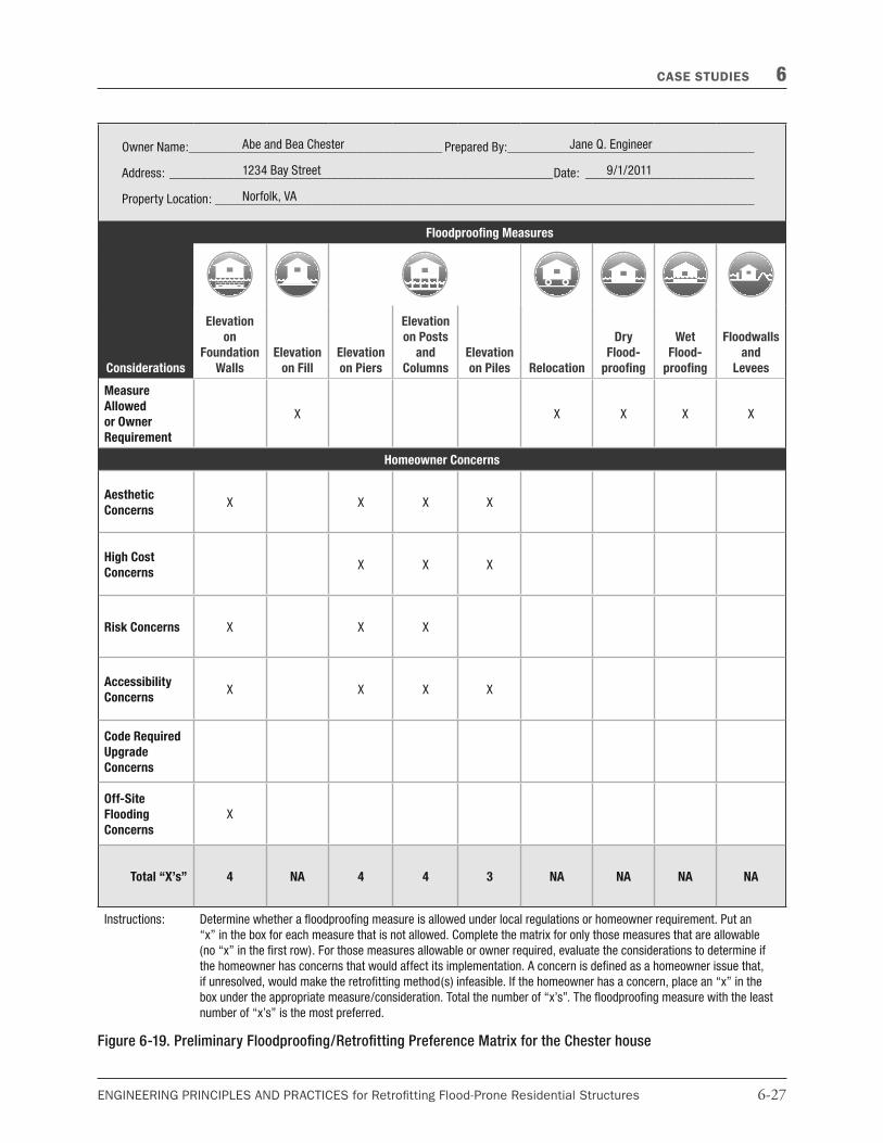
During an initial interview with the Chesters, potential retro"t options were discussed (Figure 6-19). Immediately, elevation on "ll was ruled out because it is prohibited by the local #oodplain ordinance. Similarly, dry #oodproo"ng, wet #oodproo"ng, and #oodwalls and small levees were ruled out because these measures will not bring a pre-FIRM home located in a SFHA into compliance with the NFIP. erefore, acquisition (not included in matrix) and elevation were viable options for the structure and will reduce NFIP #ood insurance rates.
Cost was a concern for all potential retro"t options. e Chesters were also concerned about building accessibility for an elevation project.
Based on the retro"t option screening matrix, the two most viable options were elevation on piers and acquisition/demolition.
Acquisition
e only way to completely eliminate the risk to the Chesters’ home is to move the entire structure out of the SFHA. Because the Chesters aren’t interested in this, but are willing to move, acquiring the house and demolishing it may be a viable option. e acquisition process would include:
4 Using HMA or other funds to purchase the home from the Chesters
4 Demolishing the existing structure
4 Restoring the site to green space
4 Maintaining the site as green space
6-27ENGINEERING PRINCIPLES AND PRACTICES for Retro�tting Flood-Prone Residential Structures
CASE STUDIES 6
Owner Name: _______________________________________ Prepared By:______________________________________
Address: ___________________________________________________________Date: __________________________
Property Location: ___________________________________________________________________________________
Considerations
Floodproofing Measures
Elevation
on
Foundation
Walls
Elevation
on Fill
Elevation
on Piers
Elevation
on Posts
and
Columns
Elevation
on Piles Relocation
Dry
Flood-
proofing
Wet
Flood-
proofing
Floodwalls
and
Levees
Measure
Allowed
or Owner
Requirement
X X X X X
Homeowner Concerns
Aesthetic
ConcernsX X X X
High Cost
ConcernsX X X
Risk Concerns X X X
Accessibility
ConcernsX X X X
Code Required
Upgrade
Concerns
Off-Site
Flooding
Concerns
X
Total “X’s” 4 NA 4 4 3 NA NA NA NA
Instructions: Determine whether a floodproofing measure is allowed under local regulations or homeowner requirement. Put an
“x” in the box for each measure that is not allowed. Complete the matrix for only those measures that are allowable
(no “x” in the first row). For those measures allowable or owner required, evaluate the considerations to determine if
the homeowner has concerns that would affect its implementation. A concern is defined as a homeowner issue that,
if unresolved, would make the retrofitting method(s) infeasible. If the homeowner has a concern, place an “x” in the
box under the appropriate measure/consideration. Total the number of “x’s”. The floodproofing measure with the least
number of “x’s” is the most preferred.
Abe and Bea Chester
1234 Bay Street
Norfolk, VA
Jane Q. Engineer
9/1/2011
Figure 6-19. Preliminary Floodproofing/Retrofitting Preference Matrix for the Chester house
6-28 ENGINEERING PRINCIPLES AND PRACTICES for Retro�tting Flood-Prone Residential Structures
6 CASE STUDIES
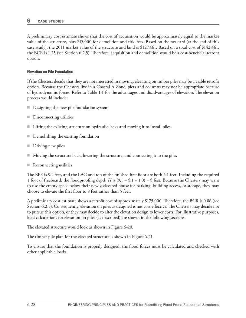
A preliminary cost estimate shows that the cost of acquisition would be approximately equal to the market value of the structure, plus $15,000 for demolition and title fees. Based on the tax card (at the end of this case study), the 2011 market value of the structure and land is $127,461. Based on a total cost of $142,461, the BCR is 1.25 (see Section 6.2.5). erefore, acquisition and demolition would be a cost-bene"cial retro"t option.
Elevation on Pile Foundation
If the Chesters decide that they are not interested in moving, elevating on timber piles may be a viable retro"t option. Because the Chesters live in a Coastal A Zone, piers and columns may not be appropriate because of hydrodynamic forces. Refer to Table 1-1 for the advantages and disadvantages of elevation. e elevation process would include:
4 Designing the new pile foundation system
4 Disconnecting utilities
4 Lifting the existing structure on hydraulic jacks and moving it to install piles
4 Demolishing the existing foundation
4 Driving new piles
4 Moving the structure back, lowering the structure, and connecting it to the piles
4 Reconnecting utilities
e BFE is 9.1 feet, and the LAG and top of the "nished "rst #oor are both 5.1 feet. Including the required 1 foot of freeboard, the #oodproo"ng depth H is (9.1 – 5.1 + 1.0) = 5 feet. Because the Chesters may want to use the empty space below their newly elevated house for parking, building access, or storage, they may choose to elevate the "rst #oor to 8 feet rather than 5 feet.
A preliminary cost estimate shows a retro"t cost of approximately $175,000. erefore, the BCR is 0.86 (see Section 6.2.5). Consequently, elevation on piles as designed is not cost e$ective. e Chesters may decide not to pursue this option, or they may decide to alter the elevation design to lower costs. For illustrative purposes, load calculations for elevation on piles (as described) are shown in the following sections.
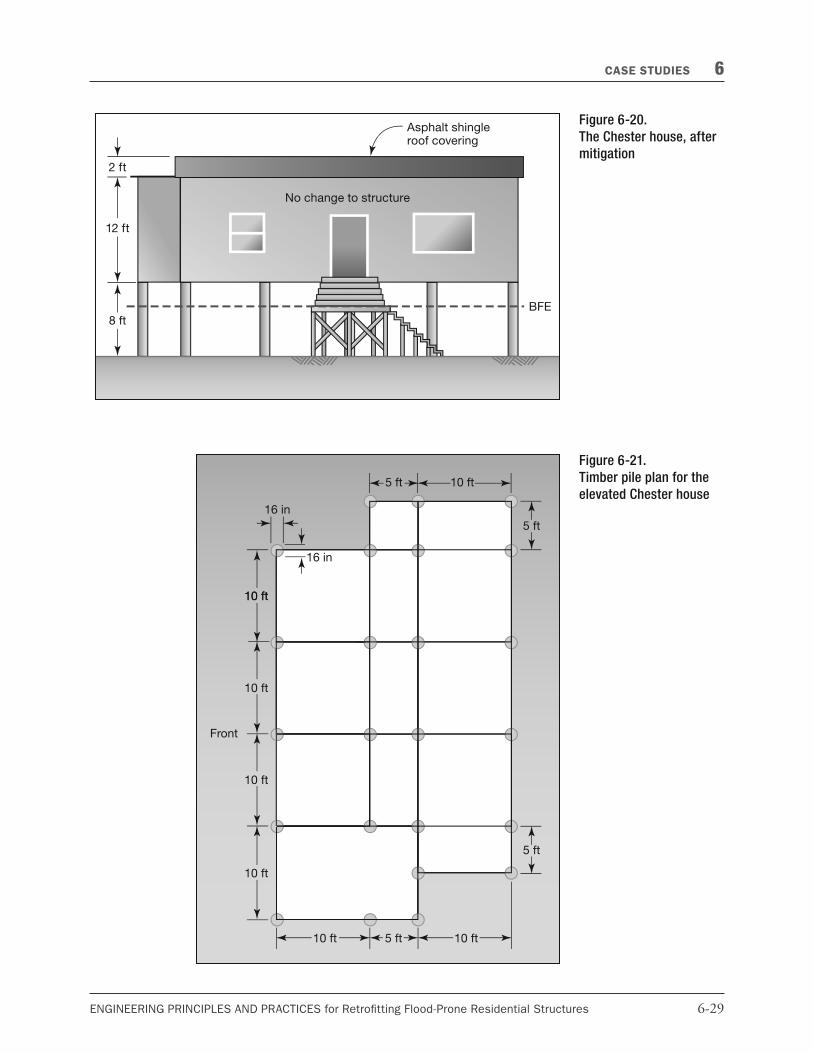
e elevated structure would look as shown in Figure 6-20.
e timber pile plan for the elevated structure is shown in Figure 6-21.
To ensure that the foundation is properly designed, the #ood forces must be calculated and checked with other applicable loads.
6-29ENGINEERING PRINCIPLES AND PRACTICES for Retro�tting Flood-Prone Residential Structures
CASE STUDIES 6
Figure 6-20.
The Chester house, after
mitigation
Figure 6-21.
Timber pile plan for the
elevated Chester house

6-30 ENGINEERING PRINCIPLES AND PRACTICES for Retro�tting Flood-Prone Residential Structures
6 CASE STUDIES
6.2.4 Load Calculations
e paragraphs that follow provide calculations for #ood loads, dead loads, live loads, and load combinations associated with the elevation option.
Load Calculations: Flood Loads
e "rst step is to calculate hydrostatic forces. As determined above, the #oodproo"ng depth H is 5 feet. Because the home is being elevated on an open foundation, the saturated soil depth is 0 feet. Because the home is being elevated on an open foundation, and because it is being supported on piles, no lateral hydrostatic or hydrodynamic forces are acting on the structure. Further, vertical hydrostatic (buoyancy) forces will be negligible.
e design #ood depth is 5 feet, therefore CD = 1.00. Assume CB = 1.0. An impact force computation worksheet is presented in Figure 6-22.
Figure 6-22. Impact Force Computation Worksheet for the Chester house (Refer to Figure 4-12)
Hydrostatic Force Computation Worksheet
Owner Name: _______________________________________ Prepared By:______________________________________
Address: ___________________________________________________________Date: __________________________
Property Location: ___________________________________________________________________________________
Variables
W = weight of the object (lbs) = 1,000 lbs
V = velocity of water (ft/sec) = 3 ft/sec
CD = depth coe&cient (see Table 4-6) = 1.00
CB = blockage coe&cient (taken as 1.0 for no upstream screening, #ow path greater than 30 ft; see Table 4-7 for more information)
CStr = building structure coe&cient
= 0.2 for timber pile and masonry column supported structures 3 stories or less in height above grade
= 0.4 for concrete pile or concrete or steel moment resisting frames 3 stories or less in height above grade
= 0.8 for reinforced concrete foundation walls (including insulated concrete forms)
Summary of Loads
fi = 600 lb
Equation 4-13: Normal Impact Loads
= (1,000 lbs)(3 ft/sec)(1.0)(1.0)(0.2) = 600 lbs
Abe and Bea Chester
1234 Bay Street
Norfolk, VA
Jane Q. Engineer
9/1/2011

6-31ENGINEERING PRINCIPLES AND PRACTICES for Retro�tting Flood-Prone Residential Structures
CASE STUDIES 6
Flood Force Summary:
Horizontal Force:
fcomb = 0 lb/lf
Fi = 600 lbs
e total #ood force acting on the six piers of the front wall (perpendicular to #ow) is:
F = 600 lbs
Vertical Force:
Fbuoy = 0 lbs
Load Calculations: Dead Loads
e dead load is the self-weight of the structure. Case Study #1 illustrates a detailed calculation of the dead load. For this case study, assume a dead weight of approximately 50 lb/ft2 over 1,025 square feet.
D = 50 lb/ft2 x (1,025 ft2) = 51,250 lbs
Load Calculations: Live Loads
Live Load (Vertical)
Per ASCE 7-10, assume a live load of:
L = 40 lb/ft2 x (1,025 ft2) = 41,000 lbs
Roof Live Load (Vertical)
Per ASCE 7-10, assume a roof live load of 20 lb/ft2. e roof live load acts on the horizontal projected area of the roof:
Lr = 20 lb/ft2 x (1,025 ft2) = 20,500 lbs
Snow Load (Vertical)
Assume a conservative snow load of 20 lb/ft2, per ASCE 7-10. e snow load also acts on the horizontal projected area of the roof.
S = 20 lb/ft2 (1,025 ft2) = 20,500 lbs
Wind Load (Horizontal)
Appendix C contains a detailed discussion of wind load calculations, including a detailed example. Refer to Appendix C for wind load calculations; this case study uses a simpli"ed approach. Using a simpli"ed wind load, assuming that the structure is fully enclosed, assume a worst case scenario wind load acting perpendicular to the structure (i.e., on the entire face of the structure facing the river). Because the roof at the front (windward side) of the house is sloped and there are no overhangs, there is no vertical wind (uplift) component on the roof. ere may be some uplift on the bottom of the structure, but it is not considered here. erefore, assume a wind pressure of 30 lb/ft2 acting uniformly over the entire aboveground structure:

6-32 ENGINEERING PRINCIPLES AND PRACTICES for Retro�tting Flood-Prone Residential Structures
6 CASE STUDIES
Area = Pier surface area (6 piers) + Exterior Wall area + Vertical Roof area
A = (6)(16 in./(12 in./ft))(5ft) + (45 ft)(16 ft) + (1/2)(2 ft)(40 ft) = 40 ft2 + 720 ft2 + 40 ft2 = 800 ft2
W = 30 lb/ft2 x (800 ft2) = 24,000 lbs
Earthquake Load
Seismic forces are not considered for this example. erefore, E = 0.
Load Combinations
IBC section 1810.1 requires that deep foundations be designed on the basis of a detailed geotechnical analysis. For that reason, failure modes are not analyzed here. For illustrative purposes, ASCE 7-10 load combinations (Allowable Stress Design) are presented in Table 6-5.
Table 6-5. Summary of Horizontal and Vertical Load Combinations for the Chester House
Combination Horizontal (lbs) Vertical (lbs)
1. D 0 51,250
2. D + L 0 92,250
3. D + (Lr or S or R ) 0 71,750
4. D + 0.75L + 0.75(Lr or S or R ) 0 97,375
5. D + (0.6W or 0.7E ) + 0.75Fa 14,850 51,250
6a. D + 0.75L + 0.75(0.6W ) + 0.75(Lr or S or R ) + 0.75Fa 11,250 97,375
6b. D + 0.75L + 0.75(0.7E ) + 0.75S + 0.75Fa 450 97,375
7. 0.6D + 0.6W + 0.75Fa 14,850 30,750
8. 0.6D + 0.7E 0 30,750
Load Summary:
Horizontal Loads
D = L = Lr = S = E = 0
Fa = Fsta = 600 lbs
W = 24,000 lbs
Vertical Loads
D = 51,250 lbs
L = 41,000 lbs
Lr = 20,500 lbs
S = 20,500 lbs
W = 0 (conservative)
E = 0
Fa = Fbuoy = 0
6-33ENGINEERING PRINCIPLES AND PRACTICES for Retro�tting Flood-Prone Residential Structures
CASE STUDIES 6
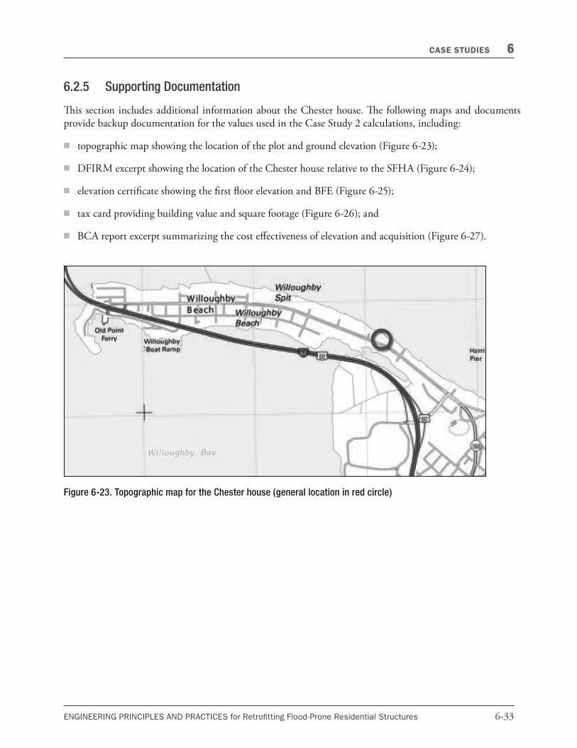
Figure 6-23. Topographic map for the Chester house (general location in red circle)
6.2.5 Supporting Documentation
is section includes additional information about the Chester house. e following maps and documents provide backup documentation for the values used in the Case Study 2 calculations, including:
4 topographic map showing the location of the plot and ground elevation (Figure 6-23);
4 DFIRM excerpt showing the location of the Chester house relative to the SFHA (Figure 6-24);
4 elevation certi"cate showing the "rst #oor elevation and BFE (Figure 6-25);
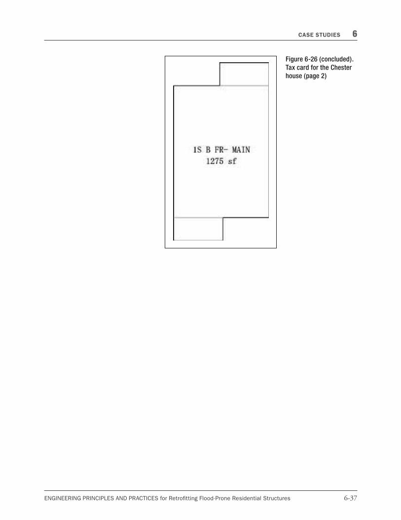
4 tax card providing building value and square footage (Figure 6-26); and
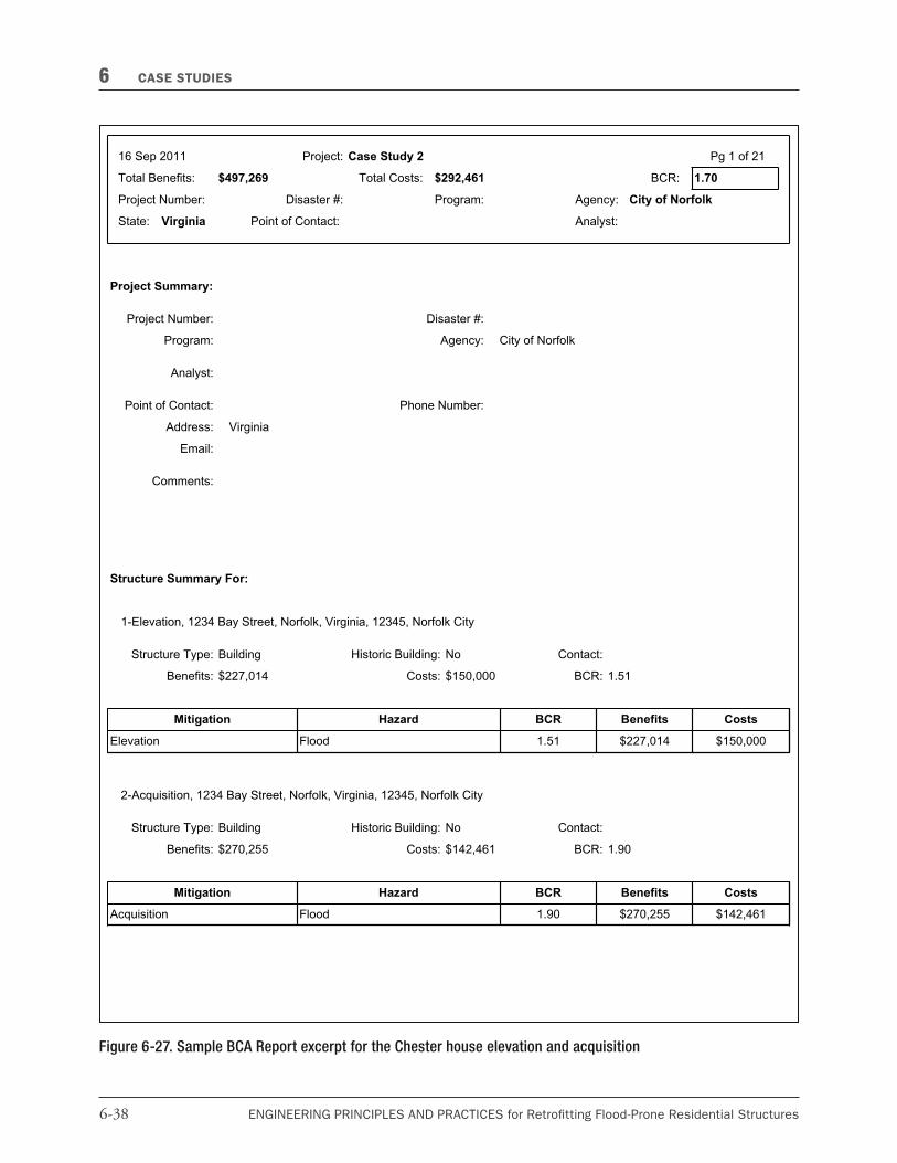
4 BCA report excerpt summarizing the cost e$ectiveness of elevation and acquisition (Figure 6-27).

6-34 ENGINEERING PRINCIPLES AND PRACTICES for Retro�tting Flood-Prone Residential Structures
6 CASE STUDIES
Figure 6-24. DFIRM excerpt and FIS excerpt: Summary of stillwater elevations for the Chester house

6-35ENGINEERING PRINCIPLES AND PRACTICES for Retro�tting Flood-Prone Residential Structures
CASE STUDIES 6
Figure 6-25. Elevation certificate excerpt for the Chester house

6-36 ENGINEERING PRINCIPLES AND PRACTICES for Retro�tting Flood-Prone Residential Structures
6 CASE STUDIES
Figure 6-26. Tax card for the Chester house (page 1)
6-37ENGINEERING PRINCIPLES AND PRACTICES for Retro�tting Flood-Prone Residential Structures
CASE STUDIES 6
Figure 6-26 (concluded).
Tax card for the Chester
house (page 2)
6-38 ENGINEERING PRINCIPLES AND PRACTICES for Retro�tting Flood-Prone Residential Structures
6 CASE STUDIES
Figure 6-27. Sample BCA Report excerpt for the Chester house elevation and acquisition
6-39ENGINEERING PRINCIPLES AND PRACTICES for Retro�tting Flood-Prone Residential Structures
CASE STUDIES 6
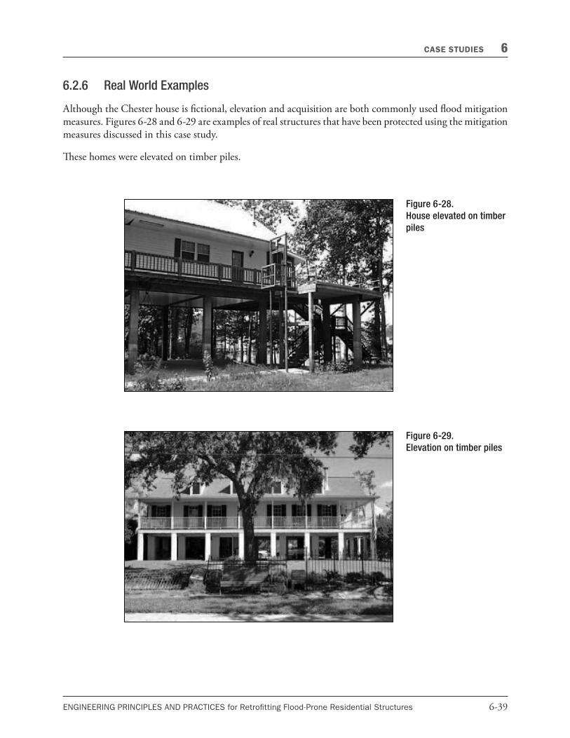
6.2.6 Real World Examples
Although the Chester house is "ctional, elevation and acquisition are both commonly used #ood mitigation measures. Figures 6-28 and 6-29 are examples of real structures that have been protected using the mitigation measures discussed in this case study.
ese homes were elevated on timber piles.
Figure 6-28.
House elevated on timber
piles
Figure 6-29.
Elevation on timber piles