Embed Size (px)
Citation preview
EN
GLI
SH
Copyright © 2013 EATON All rights reserved.
Service and support:Call your local service representative
619-00470-01-i (en)
5SC 500i5SC 750i5SC 1000i5SC 1500i
Installation and user manual
Page 2 619-00470-01-i (en)
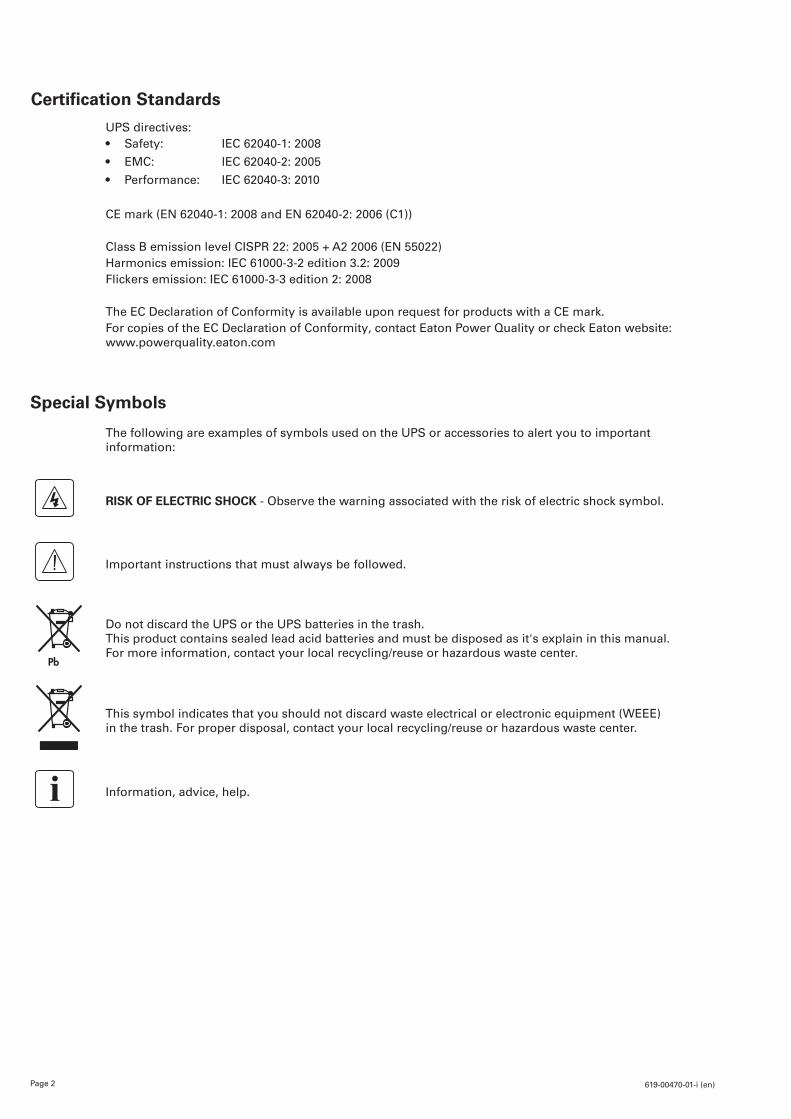
Certification Standards
Special Symbols
The following are examples of symbols used on the UPS or accessories to alert you to important information:
RISK OF ELECTRIC SHOCK - Observe the warning associated with the risk of electric shock symbol.
Important instructions that must always be followed.
Do not discard the UPS or the UPS batteries in the trash. This product contains sealed lead acid batteries and must be disposed as it's explain in this manual. For more information, contact your local recycling/reuse or hazardous waste center.
This symbol indicates that you should not discard waste electrical or electronic equipment (WEEE) in the trash. For proper disposal, contact your local recycling/reuse or hazardous waste center.
Information, advice, help.
UPS directives:• Safety: IEC 62040-1: 2008
• EMC: IEC 62040-2: 2005
• Performance: IEC 62040-3: 2010
CE mark (EN 62040-1: 2008 and EN 62040-2: 2006 (C1))
Class B emission level CISPR 22: 2005 + A2 2006 (EN 55022)Harmonics emission: IEC 61000-3-2 edition 3.2: 2009Flickers emission: IEC 61000-3-3 edition 2: 2008
The EC Declaration of Conformity is available upon request for products with a CE mark.For copies of the EC Declaration of Conformity, contact Eaton Power Quality or check Eaton website: www.powerquality.eaton.com

Page 3619-00470-01-i (en)
EN
GLI
SHContents
1. Introduction ....................................................................................... 4
1.1 Environmental protection ...................................................................................................4
2. Presentation ...................................................................................... 5
2.1 Standard installation ..........................................................................................................52.2 Rear panels ........................................................................................................................52.3 Control panel .....................................................................................................................62.4 LCD description .................................................................................................................62.5 UPS setting through the LCD ............................................................................................6
3. Installation ........................................................................................ 7
3.1 Unpacking and contents check ..........................................................................................73.2 Communication ports ........................................................................................................8
4. Operation........................................................................................... 9
4.1 Start-up and Normal operation ...........................................................................................94.2 Starting the UPS on Battery ..............................................................................................94.3 UPS Shutdown ..................................................................................................................94.4 Operation on Battery Power ..............................................................................................94.5 Return of AC Input Power ..................................................................................................9
5. Maintenance ................................................................................... 10
5.1 Troubleshooting ................................................................................................................ 105.2 Battery-module replacement ........................................................................................... 11
6. Appendices ...................................................................................... 12
6.1 Technical specifications ....................................................................................................12
Page 4 619-00470-01-i (en)
1. Introduction
Thank you for selecting an EATON product to protect your electrical equipment. The 5SC range has been designed with the utmost care.We recommend that you take the time to read this manual to take full advantage of the many features of your UPS (Uninterruptible Power System). Before installing 5SC, please read the booklet presenting the safety instructions. Then follow the instructions in this manual. To discover the entire range of EATON products and the options available for the 5SC range, we invite you to visit our web site at www.eaton.com/powerquality or contact your EATON representative.
1.1 Environmental protection
EATON has implemented an environmental-protection policy.Products are developed according to an eco-design approach.
Substances
This product does not contain CFCs, HCFCs or asbestos.
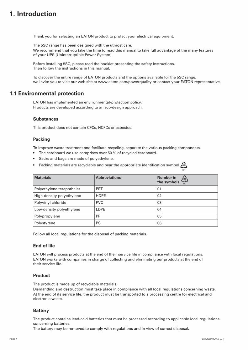
Packing
To improve waste treatment and facilitate recycling, separate the various packing components.• The cardboard we use comprises over 50 % of recycled cardboard.
• Sacks and bags are made of polyethylene.
• Packingmaterialsarerecyclableandbeartheappropriateidentificationsymbol 01
PET
Materials Abbreviations Number in the symbols
Polyethylene terephthalat PET 01
High-density polyethylene HDPE 02
Polyvinyl chloride PVC 03
Low-density polyethylene LDPE 04
Polypropylene PP 05
Polystyrene PS 06
Follow all local regulations for the disposal of packing materials.
End of life
EATON will process products at the end of their service life in compliance with local regulations.EATON works with companies in charge of collecting and eliminating our products at the end of their service life.
Product
The product is made up of recyclable materials.Dismantling and destruction must take place in compliance with all local regulations concerning waste.At the end of its service life, the product must be transported to a processing centre for electrical and electronic waste.
Battery
The product contains lead-acid batteries that must be processed according to applicable local regulations concerning batteries. The battery may be removed to comply with regulations and in view of correct disposal.
01
PET

Page 5619-00470-01-i (en)
EN
GLI
SH2. Presentation
2.1 Standard installation
D
H
W
Description Weights (kg/lb) Dimensions (mm/inch) D x W x H
5SC 500i 6.60 / 14.60 240 x 150 x 210 / 9.4 x 5.9 x 8.35SC 750i 10.40 / 22.90 340 x 150 x 210 / 13.4 x 5.9 x 8.35SC 1000i 11.10 / 24.50 340 x 150 x 210 / 13.4 x 5.9 x 8.35SC 1500i 15.20 / 33.50 410 x 150 x 210 / 16.1 x 5.9 x 8.3
2.2 Rear panels
5SC 500i 5SC 750i
INPUT
OUTPUT
Refer to the Bottom ofthe unit for caution markings!
RS232 OR
5
4
3
2
1
INPUT
OUTPUT
Refer to the Bottom ofthe unit for caution markings!
RS232 OR5
4
3
2
1
5SC 1000i 5SC 1500i
INPUT
OUTPUT
OUTPUT
Refer to the Bottom ofthe unit for caution markings!
RS232 OR5
4
3
2
1
INPUT
OUTPUT
Refer to the Bottom ofthe unit for caution markings!
RS232 OR5
4
3
2
1
(1) USB communication port(2) RS232 communication port(3) Outlets for connection of critical equipment(4) Socket for connection to AC-power source(5) Ground screw
Page 6 619-00470-01-i (en)
2. Presentation
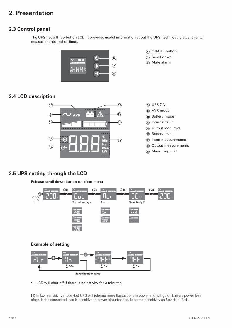
2.3 Control panel
The UPS has a three-button LCD. It provides useful information about the UPS itself, load status, events, measurements and settings.
AVR
%MinHzkVAkW
6
7
8
6 ON/OFF button
7 Scroll down
8 Mute alarm
2.4 LCD description
16
15
14
17
1110
9 12
13
9 UPS ON
10 AVR mode
11 Battery mode
12 Internal fault
13 Output load level
14 Battery level
15 Input measurements
16 Output measurements
17 Measuring unit
2.5 UPS setting through the LCD
Release scroll down button to select menu
5s 2s 2s 2s
Output voltage Alarm Sensitivity (1)
Example of setting
Save the new value
10s 5s 5s
• LCD will shut off if there is no activity for 3 minutes.
(1) In low sensitivity mode (Lo) UPS will tolerate more fluctuations in power and will go on battery power less often. If the connected load is sensitive to power disturbances, keep the sensitivity as Standard (Std).
Page 7619-00470-01-i (en)
EN
GLI
SH3. Installation
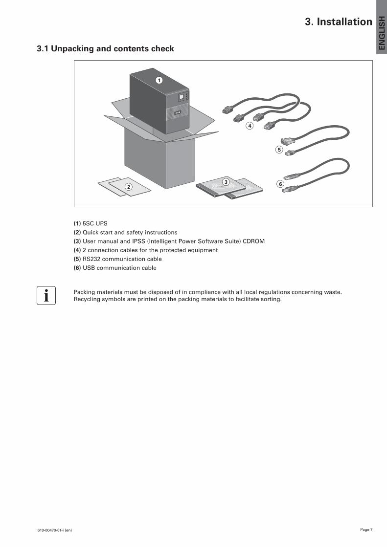
3.1 Unpacking and contents check
1
23
4
5
6
(1) 5SC UPS
(2) Quick start and safety instructions
(3) User manual and IPSS (Intelligent Power Software Suite) CDROM
(4) 2 connection cables for the protected equipment
(5) RS232 communication cable
(6) USB communication cable
Packing materials must be disposed of in compliance with all local regulations concerning waste. Recycling symbols are printed on the packing materials to facilitate sorting.
Page 8 619-00470-01-i (en)
3. Installation
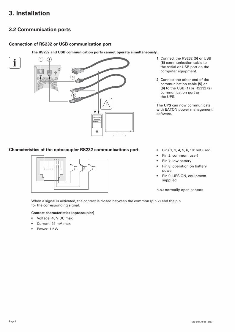
3.2 Communication ports
Connection of RS232 or USB communication port
The RS232 and USB communication ports cannot operate simultaneously.
21
5
6
1. Connect the RS232 (5) or USB (6) communication cable to the serial or USB port on the computer equipment.
2. Connect the other end of the communication cable (5) or (6) to the USB (1) or RS232 (2) communication port on the UPS.
The UPS can now communicate with EATON power management software.
Characteristics of the optocoupler RS232 communications port • Pins 1, 3, 4, 5, 6, 10: not used
• Pin 2: common (user)
• Pin 7: low battery
• Pin 8: operation on battery power
• Pin 9: UPS ON, equipment supplied
n.o.: normally open contact
When a signal is activated, the contact is closed between the common (pin 2) and the pin for the corresponding signal.
Contact characteristics (optocoupler)
• Voltage: 48 V DC max
• Current: 25 mA max
• Power: 1.2 W
Page 9619-00470-01-i (en)
EN
GLI
SH4. Operation
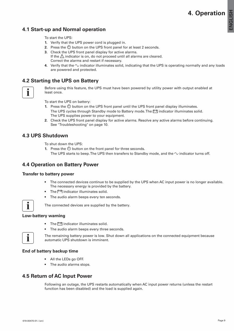
4.1 Start-up and Normal operation
To start the UPS:1. Verify that the UPS power cord is plugged in.2. Press the button on the UPS front panel for at least 2 seconds.3. Check the UPS front panel display for active alarms.
If the indicator is on, do not proceed until all alarms are cleared. Correct the alarms and restart if necessary.
4. Verify that the indicator illuminates solid, indicating that the UPS is operating normally and any loads are powered and protected.
4.2 Starting the UPS on BatteryBefore using this feature, the UPS must have been powered by utility power with output enabled at least once.
To start the UPS on battery:1. Press the button on the UPS front panel until the UPS front panel display illuminates. The UPS cycles through Standby mode to Battery mode. The indicator illuminates solid.
The UPS supplies power to your equipment.2. Check the UPS front panel display for active alarms. Resolve any active alarms before continuing.
See "Troubleshooting" on page 10.
4.3 UPS Shutdown
To shut down the UPS:1. Press the button on the front panel for three seconds. The UPS starts to beep. The UPS then transfers to Standby mode, and the indicator turns off.
4.4 Operation on Battery Power
Transfer to battery power
• The connected devices continue to be supplied by the UPS when AC input power is no longer available. The necessary energy is provided by the battery.
• The indicator illuminates solid.
• The audio alarm beeps every ten seconds.
The connected devices are supplied by the battery.
Low-battery warning
• The indicator illuminates solid.
• The audio alarm beeps every three seconds.
The remaining battery power is low. Shut down all applications on the connected equipment because automatic UPS shutdown is imminent.
End of battery backup time
• All the LEDs go OFF.
• The audio alarms stops.
4.5 Return of AC Input Power
Following an outage, the UPS restarts automatically when AC input power returns (unless the restart function has been disabled) and the load is supplied again.
Page 10 619-00470-01-i (en)
5. Maintenance
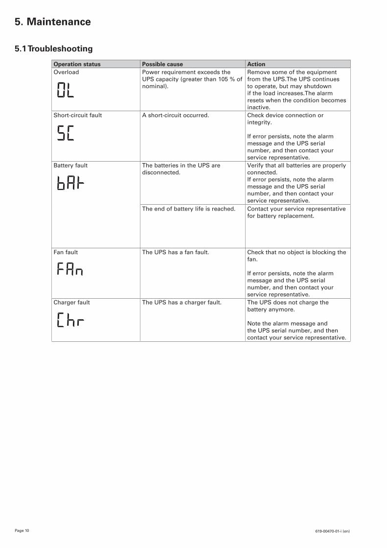
5.1 Troubleshooting
Operation status Possible cause ActionOverload Power requirement exceeds the
UPS capacity (greater than 105 % of nominal).
Remove some of the equipment from the UPS.The UPS continues to operate, but may shutdown if the load increases.The alarm resets when the condition becomes inactive.
Short-circuit fault A short-circuit occurred. Check device connection or integrity.
If error persists, note the alarm message and the UPS serial number, and then contact your service representative.
Battery fault The batteries in the UPS are disconnected.
Verify that all batteries are properly connected.If error persists, note the alarm message and the UPS serial number, and then contact your service representative.
The end of battery life is reached. Contact your service representative for battery replacement.
Fan fault The UPS has a fan fault. Check that no object is blocking the fan.
If error persists, note the alarm message and the UPS serial number, and then contact your service representative.
Charger fault The UPS has a charger fault. The UPS does not charge the battery anymore.
Note the alarm message and the UPS serial number, and then contact your service representative.
Page 11619-00470-01-i (en)
EN
GLI
SH5. Maintenance
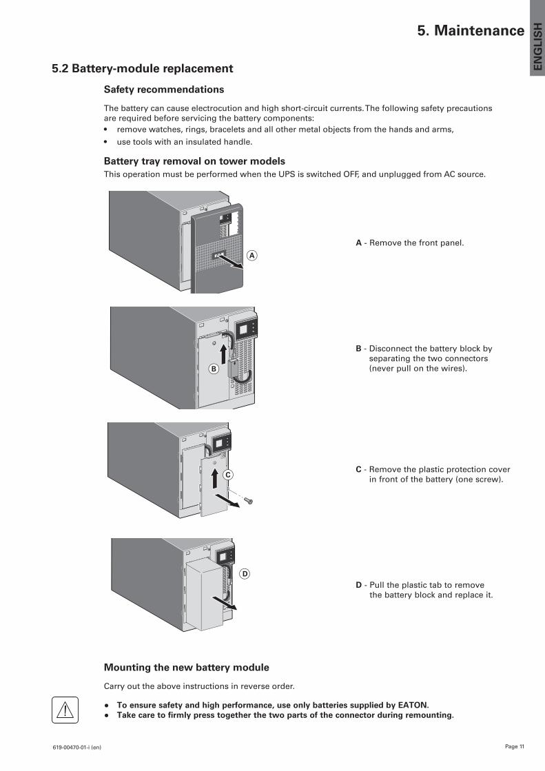
5.2 Battery-module replacement
Safety recommendations
The battery can cause electrocution and high short-circuit currents. The following safety precautions are required before servicing the battery components:• remove watches, rings, bracelets and all other metal objects from the hands and arms,
• use tools with an insulated handle.
Battery tray removal on tower modelsThis operation must be performed when the UPS is switched OFF, and unplugged from AC source.
A
A - Remove the front panel.
B
B - Disconnect the battery block by separating the two connectors (never pull on the wires).
CC - Remove the plastic protection cover
in front of the battery (one screw).
D
D - Pull the plastic tab to remove the battery block and replace it.
Mounting the new battery module
Carry out the above instructions in reverse order.
● To ensure safety and high performance, use only batteries supplied by EATON.● Take care to firmly press together the two parts of the connector during remounting.
Page 12 619-00470-01-i (en)
6. Appendices
6.1 Technical specifications
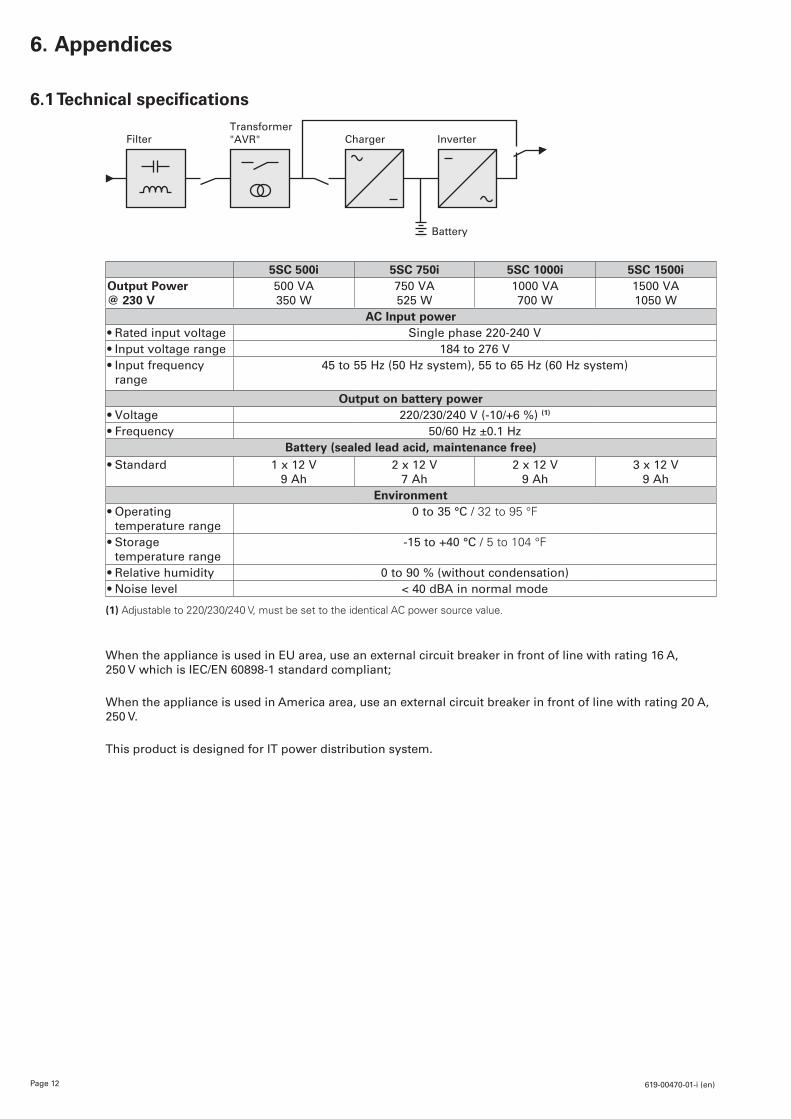
5SC 500i 5SC 750i 5SC 1000i 5SC 1500iOutput Power @ 230 V
500 VA 350 W
750 VA 525 W
1000 VA 700 W
1500 VA 1050 W
AC Input power•Rated input voltage Single phase 220-240 V•Input voltage range 184 to 276 V• Input frequency
range45 to 55 Hz (50 Hz system), 55 to 65 Hz (60 Hz system)
Output on battery power•Voltage 220/230/240 V (-10/+6 %) (1)
•Frequency 50/60 Hz ±0.1 HzBattery (sealed lead acid, maintenance free)
•Standard 1 x 12 V 9 Ah
2 x 12 V 7 Ah
2 x 12 V 9 Ah
3 x 12 V 9 Ah
Environment• Operating
temperature range0 to 35 °C / 32 to 95 °F
• Storage temperature range
-15 to +40 °C / 5 to 104 °F
•Relative humidity 0 to 90 % (without condensation)•Noise level < 40 dBA in normal mode
(1) Adjustable to 220/230/240 V, must be set to the identical AC power source value.
When the appliance is used in EU area, use an external circuit breaker in front of line with rating 16 A, 250 V which is IEC/EN 60898-1 standard compliant;
When the appliance is used in America area, use an external circuit breaker in front of line with rating 20 A, 250 V.
This product is designed for IT power distribution system.
FilterTransformer "AVR" Charger Inverter
Battery