Embed Size (px)
Citation preview

Relion® Protection and Control
615 series ANSIEngineering Manual


Document ID: 1MAC108982-MBIssued: 2011-06-16
Revision: BProduct version: 4.0
© Copyright 2011 ABB. All rights reserved

CopyrightThis document and parts thereof must not be reproduced or copied without writtenpermission from ABB, and the contents thereof must not be imparted to a third party,nor used for any unauthorized purpose.
The software or hardware described in this document is furnished under a license andmay be used, copied, or disclosed only in accordance with the terms of such license.
TrademarksABB and Relion are registered trademarks of ABB Group. All other brand or productnames mentioned in this document may be trademarks or registered trademarks of theirrespective holders.
WarrantyPlease inquire about the terms of warranty from your nearest ABB representative.
ABB Inc.
Distribution Automation
4300 Coral Ridge Drive
Coral Springs, FL 33065, USA
Toll-free: 1 (800) 523-2620
Phone: +1 954-752-6700
Fax: +1 954 345-5329
http://www.abb.com/substationautomation

DisclaimerThe data, examples and diagrams in this manual are included solely for the concept orproduct description and are not to be deemed as a statement of guaranteed properties.All persons responsible for applying the equipment addressed in this manual mustsatisfy themselves that each intended application is suitable and acceptable, includingthat any applicable safety or other operational requirements are complied with. Inparticular, any risks in applications where a system failure and/or product failure wouldcreate a risk for harm to property or persons (including but not limited to personalinjuries or death) shall be the sole responsibility of the person or entity applying theequipment, and those so responsible are hereby requested to ensure that all measuresare taken to exclude or mitigate such risks.
This document has been carefully checked by ABB but deviations cannot becompletely ruled out. In case any errors are detected, the reader is kindly requested tonotify the manufacturer. Other than under explicit contractual commitments, in noevent shall ABB be responsible or liable for any loss or damage resulting from the useof this manual or the application of the equipment.

ConformityThis product complies with the directive of the Council of the European Communitieson the approximation of the laws of the Member States relating to electromagneticcompatibility (EMC Directive 2004/108/EC) and concerning electrical equipment foruse within specified voltage limits (Low-voltage directive 2006/95/EC). Thisconformity is the result of tests conducted by ABB in accordance with the productstandards EN 50263 and EN 60255-26 for the EMC directive, and with the productstandards EN 60255-1 and EN 60255-27 for the low voltage directive. The IED isdesigned in accordance with the international standards of the IEC 60255 series andANSI C37.90.

Safety information
Dangerous voltages can occur on the connectors, even though theauxiliary voltage has been disconnected.
Non-observance can result in death, personal injury or substantialproperty damage.
Only a competent electrician is allowed to carry out the electricalinstallation.
National and local electrical safety regulations must always be followed.
The frame of the IED has to be carefully grounded.
When the plug-in unit has been detached from the case, do not touch the insideof the case. The IED case internals may contain high voltage potential andtouching these may cause personal injury.
The IED contains components which are sensitive to electrostaticdischarge. Unnecessary touching of electronic components musttherefore be avoided.
Whenever changes are made in the IED, measures should be taken toavoid inadvertent tripping.


Table of contents
Section 1 Introduction............................................................................5This manual..............................................................................................5Intended audience....................................................................................5Product documentation.............................................................................6
Product documentation set..................................................................6Document revision history...................................................................7Related documentation........................................................................8
Symbols and conventions.........................................................................8Safety indication symbols....................................................................8Manual conventions.............................................................................8
Section 2 IED engineering process.....................................................11Monitoring and control system structure.................................................13Standard configuration concept..............................................................14Workflow.................................................................................................16
Section 3 PCM600 tool........................................................................19Connectivity packages............................................................................21PCM600 and IED connectivity package version.....................................21PCM600 projects....................................................................................21Communication between PCM600 and the IED.....................................22
Section 4 Setting up a project.............................................................25Installing connectivity packages.............................................................25Activating connectivity packages............................................................25Setting up communication between PCM600 and the IED.....................27
Setting up IP addresses....................................................................27Setting up the PC or workstation for point-to-point access tothe IED's front port.............................................................................28
Creating a new project............................................................................31Building the plant structure.....................................................................32Inserting an IED......................................................................................33
Inserting an IED in online mode........................................................34Inserting an IED in offline mode........................................................42Inserting an IED from the template directory.....................................44Inserting an IED by importing a .pcmi file..........................................45
Setting the IED IP address in a project...................................................48
Table of contents
615 series ANSI 1Engineering Manual

Technical key..........................................................................................50IEC 61850 naming conventions to identify an IED............................51Setting the technical key....................................................................53
COM600 project......................................................................................56Importing a 615 series IED in a COM600 project..............................56
Using the Web HMI.................................................................................60IED User Management...........................................................................61
Section 5 Protection and control engineering......................................65Application Configuration tool.................................................................65
Function blocks..................................................................................66Signals and signal management.......................................................67Function block execution parameters................................................68Execution order and feedback loops.................................................69Configuration parameters..................................................................70Connections and variables................................................................70Hardware channels............................................................................71Validation...........................................................................................72
Validation when creating an application configuration..................72Validation on demand...................................................................73Validation when writing to the IED................................................74
Parameter Setting tool............................................................................74Configuration parameter....................................................................75Setting parameter..............................................................................75Setting group.....................................................................................75IED parameter organization...............................................................75
Signal Matrix tool....................................................................................75Load Profile tool......................................................................................78
Opening and closing Load Profile tool...............................................78Load Profile tool user interface..........................................................81Information fields...............................................................................82
Fault Record tool....................................................................................82Opening and closing Fault Record tool.............................................82Fault Record tool interface................................................................84
Section 6 LHMI engineering................................................................85Single-line diagram engineering.............................................................85
Diagrams in Graphical Display Editor................................................85Display window and sequence order............................................86Symbol library...............................................................................87Supported single-line diagram symbols........................................87
Table of contents
2 615 series ANSIEngineering Manual

HMI display raster layout and text font selection..........................89Text handling................................................................................89Adding static text..........................................................................89Adding a measurand....................................................................90Adding a busbar...........................................................................91Adding symbols into a display page.............................................92Drawing lines to create links.........................................................93
Bay configuration engineering...........................................................94Creating a complete HMI display page.........................................94Linking process objects................................................................96
Section 7 IEC 61850 communication engineering..............................99IEC 61850 protocol references and pre-conditions................................99IEC 61850 interface................................................................................99
IEC 61850 interface in the IED........................................................100GOOSE data exchange..............................................................100
Function view for IEC 61850 in PCM600.........................................101Station configuration description file types......................................102
IEC 61850 engineering process...........................................................102Exporting SCL files from PCM600...................................................103
Exporting SCD files....................................................................103Exporting ICD or CID files..........................................................105
Engineering vertical and horizontal communication........................106Importing SCL files to PCM600.......................................................107
Importing SCD files.....................................................................107Importing ICD or CID files...........................................................110
Writing communication configuration to the IED..............................110
Section 8 Glossary............................................................................113
Table of contents
615 series ANSI 3Engineering Manual

4

Section 1 Introduction
1.1 This manual
The engineering manual contains instructions on how to engineer the IEDs using thedifferent tools in PCM600. The manual provides instructions on how to set up aPCM600 project and insert IEDs to the project structure. The manual also recommendsa sequence for engineering of protection and control functions, LHMI functions as wellas communication engineering for IEC 61850 and other supported protocols.
1.2 Intended audience
This manual addresses system and project engineers involved in the engineeringprocess of a project, and installation and commissioning personnel, who use technicaldata during engineering, installation and commissioning, and in normal service.
The system engineer must have a thorough knowledge of protection and/or controlsystems, protection and/or control equipment, protection and/or control functions andthe configured functional logics in the IEDs. The installation and commissioningpersonnel must have a basic knowledge of handling electronic equipment.
1MAC108982-MB B Section 1Introduction
615 series ANSI 5Engineering Manual

1.3 Product documentation
1.3.1 Product documentation set
Pla
nnin
g &
pur
chas
e
Eng
inee
ring
Inst
allin
g
Com
mis
sion
ing
Ope
ratio
n
Mai
nten
ance
Dec
omm
issi
onin
gde
inst
allin
g&
dis
posa
l
Application manual
Operation manual
Installation manual
Service manual
Engineering manual
Commissioning manual
Communication protocolmanual
Technical manual
Pla
nnin
g &
pur
chas
e
Eng
inee
ring
Inst
allin
g
Com
mis
sion
ing
Ope
ratio
n
Mai
nten
ance
Dec
omm
issi
onin
gde
inst
allin
g&
dis
posa
l
Pla
nnin
g &
pur
chas
e
Eng
inee
ring
Inst
allin
g
Com
mis
sion
ing
Ope
ratio
n
Mai
nten
ance
Dec
omm
issi
onin
gde
inst
allin
g&
dis
posa
l
Application manualApplication manual
Operation manualOperation manual
Installation manualInstallation manual
Service manualService manual
Engineering manualEngineering manual
Commissioning manualCommissioning manual
Communication protocolmanualCommunication protocolmanual
Technical manualTechnical manual
en07000220.vsd
IEC07000220 V1 EN
Figure 1: The intended use of manuals in different lifecycles
The engineering manual contains instructions on how to engineer the IEDs using thedifferent tools in PCM600. The manual provides instructions on how to set up aPCM600 project and insert IEDs to the project structure. The manual also recommendsa sequence for engineering of protection and control functions, LHMI functions as wellas communication engineering for IEC 61850 and other supported protocols.
The installation manual contains instructions on how to install the IED. The manualprovides procedures for mechanical and electrical installation. The chapters areorganized in chronological order in which the IED should be installed.
The commissioning manual contains instructions on how to commission the IED. Themanual can also be used by system engineers and maintenance personnel for assistance
Section 1 1MAC108982-MB BIntroduction
6 615 series ANSIEngineering Manual

during the testing phase. The manual provides procedures for checking of externalcircuitry and energizing the IED, parameter setting and configuration as well asverifying settings by secondary injection. The manual describes the process of testingan IED in a substation which is not in service. The chapters are organized inchronological order in which the IED should be commissioned.
The operation manual contains instructions on how to operate the IED once it has beencommissioned. The manual provides instructions for monitoring, controlling andsetting the IED. The manual also describes how to identify disturbances and how toview calculated and measured power grid data to determine the cause of a fault.
The service manual contains instructions on how to service and maintain the IED. Themanual also provides procedures for de-energizing, de-commissioning and disposal ofthe IED.
The application manual contains application descriptions and setting guidelines sortedper function. The manual can be used to find out when and for what purpose a typicalprotection function can be used. The manual can also be used when calculating settings.
The technical manual contains application and functionality descriptions and listsfunction blocks, logic diagrams, input and output signals, setting parameters andtechnical data sorted per function. The manual can be used as a technical referenceduring the engineering phase, installation and commissioning phase, and during normalservice.
The communication protocol manual describes a communication protocol supported bythe IED. The manual concentrates on vendor-specific implementations.
The point list manual describes the outlook and properties of the data points specific tothe IED. The manual should be used in conjunction with the correspondingcommunication protocol manual.
Some of the manuals are not available yet.
1.3.2 Document revision historyDocument revision/date Product series version HistoryA/2011-04-15 4.0 First release
B/2011-06-16 4.0 Content updated
1MAC108982-MB B Section 1Introduction
615 series ANSI 7Engineering Manual
Download the latest documents from the ABB web site http://www.abb.com/substationautomation.
1.3.3 Related documentationProduct series- and product-specific manuals can be downloaded from the ABB website http://www.abb.com/substationautomation.
1.4 Symbols and conventions
1.4.1 Safety indication symbols
The caution icon indicates important information or warning related tothe concept discussed in the text. It might indicate the presence of ahazard which could result in corruption of software or damage toequipment or property.
The information icon alerts the reader to important facts and conditions.
The tip icon indicates advice on, for example, how to design yourproject or how to use a certain function.
Although warning hazards are related to personal injury, it should be understood thatoperation of damaged equipment could, under certain operational conditions, result indegraded process performance leading to personal injury or death. Therefore, complyfully with all warning and caution notices.
1.4.2 Manual conventionsConventions used in IED manuals. A particular convention may not be used in thismanual.
• Abbreviations and acronyms in this manual are spelled out in the glossary. Theglossary also contains definitions of important terms.
• Push button navigation in the LHMI menu structure is presented by using the pushbutton icons, for example:
Section 1 1MAC108982-MB BIntroduction
8 615 series ANSIEngineering Manual

To navigate between the options, use and .• HMI menu paths are presented in bold, for example:
Select Main menu/Settings.• LHMI messages are shown in Courier font, for example:
To save the changes in non-volatile memory, select Yes and press .• Parameter names are shown in italics, for example:
The function can be enabled and disabled with the Operation setting.• Parameter values are indicated with quotation marks, for example:
The corresponding parameter values are "Enabled" and "Disabled".• IED input/output messages and monitored data names are shown in Courier font,
for example:When the function picks up, the PICKUP output is set to TRUE.
• Dimensions are provided both in inches and mm. If it is not specifically mentionedthen the dimension is in mm.
1MAC108982-MB B Section 1Introduction
615 series ANSI 9Engineering Manual

10

Section 2 IED engineering process
PCM600 is used for various tasks in the IED engineering process.
• IED engineering management• Organizing the bay IEDs in the structure of the substation by defining
voltage levels and bays below the substation. PCM600 manages the project.• Configuring the IED functions (for example, protection and control
functions) by using the Application Configuration tool.• Configuring the parameters and setting values for the IED itself and for the
process functions by using the Parameter Setting tool.• Drawing single-line diagrams and making links to dynamic process values
by using the Graphical Display Editor. The single-line diagrams aredisplayed in LHMI on the bay IED.
• Configuring connections between the application configuration functionblocks and physical hardware input and outputs by using the Signal Matrixtool.
• Communication management• IEC 61850 station communication engineering is done with a separate tool,
for example, CCT600 or IET600. PCM600 interacts with CCT600 orIET600 by importing and exporting SCL files.
• Configuring the GOOSE receive data connections to the IED's applicationconfiguration function blocks by using the Application Configuration tooland the Signal Matrix tool.
• Configuring protocol data mapping for Modbus or DNP3 with theCommunication Management tool.
• Disturbance record management• Generating overviews on the available (digital fault) recordings in all
connected protection IEDs by using the Disturbance Handling tool.• Manually reading the recording files (in the COMTRADE format) from the
protection IEDs by using the Disturbance Handling tool or automatically byusing the PCM600 Scheduler.
• Managing recording files with the Disturbance Handling tool.• Creating recording file content overview reports for fast evaluation with
assistance of the Disturbance Handling tool.
• Service management
1MAC108982-MB B Section 2IED engineering process
615 series ANSI 11Engineering Manual

• Monitoring the selected signals of an IED for commissioning or servicepurposes by using the Signal Monitoring tool and Event Viewer tool.
GUID-AEEFCDDD-591F-4555-A6D5-78FC69BF623F V3 EN
Figure 2: Organization of PCM600 in different management tasks
There are also additional functions for managing projects and organizing user rights.
• PCM600 user management• Organizing users regarding their rights, profiles and passwords to use
different tools and functions in the tools.• Defining allowed activities for user profiles to use tools in PCM600.
Once the engineering of the IED is finished, the results must be written to the IED.
The connection between the physical IED and PCM600 is established via an Ethernetlink on the front or rear port on the IED.
Section 2 1MAC108982-MB BIED engineering process
12 615 series ANSIEngineering Manual

2.1 Monitoring and control system structure
The monitoring and control system for electrical substations contains a number ofIEDs for various purposes.
See PCM600 documentation for the recommended size of a project.Larger projects can be divided into several PCM600 projects.
IEC08000101.vsd
Bay level
Station level
StationCommunication
Station bus
bayIED 1
bayIED 2
bayIED n-1
bayIED n
NCC-GW(station-IED2)
PCM600(tool set)
HSI(station-IED1)
IEC08000101 V1 EN
Figure 3: Principle structure of a monitoring and control system for a substation
The monitoring and control system can be divided into three main parts.
• Bay level IEDs• Station communication• Station level IEDs
All three parts require specific engineering and configuration.
The plant structure is used to identify each IED in its location within the substationorganization. Plant structure is a logical image of the substation and the bays within thesubstation. The organization structure for the IEDs may differ from the structure of theprimary equipment in the substation.
In PCM600 it is possible to set up a hierarchical structure of five levels for the IEDidentification.
1MAC108982-MB B Section 2IED engineering process
615 series ANSI 13Engineering Manual

• Project• Substation = name of the substation• Voltage level = identifies to which grid type or part the IED belongs in the substation• Bay = bay within the voltage level• IED = the selection of the IED that is used in the bay; it is possible to insert
several IEDs within a bay, for example, one control IED and two protection IEDs
2.2 Standard configuration concept
The 615 series covers products developed for the protection of medium voltageapplications. Every 615 series product has predefined application-specific softwarecalled standard configuration that contains protection, control, supervision andmeasurement function blocks and default logical connections; for more information,see the application manuals. The product also includes the standard configurationspecific default single-line diagram.
The standard configuration software consists of connections between an application'sfunctions developed according to the needs of a particular functional application. Theinputs and outputs are similarly assigned to a default set of connections such asposition indication and Master trip. The alarm LEDs are assigned to defaultconnections based on the order number.
Current and voltage channels for protection and measurement functionsare fixed as a part of standard configuration and cannot be reassignedwith Signal Matrix or Application Configuration in PCM600.
The single-line diagram consists of an application-specific general arrangement of asingle-line diagram that includes position indications and the selection of controllableobjects and measurements.
The content of the standard configuration depends on the intended functionalapplication. The standard configurations also have selectable software options, whichare selected when ordering the IED. Some of the software options are related to theIED hardware.
The standard configurations can be used as is, but they can also be modified by usingthe PCM600. The standard configuration itself can be modified or extended by usingthe Application Configuration tool, the Signal Matrix tool and the communicationconfiguration tools. The single-line diagram can also be modified with the GraphicalDisplay Editor.
Section 2 1MAC108982-MB BIED engineering process
14 615 series ANSIEngineering Manual

Some of the standard configurations offers very wide functionality in means of numberof different functions available as part of the product configuration. It is possible to useall of the offered functions at the same time.
However, if unused function blocks are removed from the configuration with theApplication Configuration, more resources in the IED can be used for other purposes,for example :
• More advanced user application logic with Application Configuration• Extensive use of GOOSE sending and receiving• Increasing the amount of data reported for IEC 61850 clients
1MAC108982-MB B Section 2IED engineering process
615 series ANSI 15Engineering Manual

2.3 Workflow
IEC09000623-3-en.vsd
Make GOOSE connections
Export SCL files from PCM600
Import SCL files to CCT600or IET600 and do signal engineering. Export updated SCL files from CCT600 or IET600.
Import SCL files to PCM600
Start
ACTSMT
PST
GDE
SMT
CMTACT
ExportSCD
CCT600or
IET600
ImportSCD
IEDWRITE
End
Configure IED functionality
Parametrization
Signal engineering
Create single line diagramfor local HMI
Save the work between the
different steps
ProjectCreate plant structure and insert IED objects
IEC 61850DNP 3.0 IEC 60870-5-103
Write configuration to IED
IEC09000623 V3 EN
Figure 4: IED engineering workflow proposal based on practical experience anddependencies of the steps
It is possible to make a different kind of a sequence based on the information availableat the time when the project is started. This means that several iterations may beneeded to finish the project.
Setting up a PCM600 project
Section 2 1MAC108982-MB BIED engineering process
16 615 series ANSIEngineering Manual
• The plant structure is built according to the substation structure.
See PCM600 documentation for the recommended size of aproject. Larger projects can be divided into several PCM600 projects.
• In order to add an IED to a project, a suitable ConnPack is needed. IEDs can beadded either while connected, disconnected or through other means such as an IEDtemplate.
• IED objects are uniquely named within the PCM600 project.
Application configuration in the Application Configuration tool
• Protection and control functions can be configured as needed.• The configuration made in the Application Configuration tool is saved to make the
interfaces and signals available for other engineering tools within PCM600, forexample, for the Parameter Setting tool.
Parameter setting and configuration in the Parameter Setting tool
• Configuration parameters such as CT and VT conversion values of the transformermodule are checked by the tool.
• If needed, the setting values are checked and adjusted with the Parameter Settingtool.
Single-line diagram configuration in the Graphical Display Editor
• It is possible to create a single-line diagram for the switching devices in the bay.• Measurements can be included when needed.• The dynamic elements are linked to the functions created in the Application
Configuration tool; for example, a breaker object is linked to the circuit breakercontrol function.
LHMI engineering
• The LED behavior is defined with Parameter Setting.• The LEDs are configured with Application Configuration.
Communication protocol engineering
• The communication engineering details are protocol dependent.• The connectivity package creates the IEC 61850 configuration for vertical
communication automatically and it is directly suitable, in most cases, for IEC
1MAC108982-MB B Section 2IED engineering process
615 series ANSI 17Engineering Manual

61850 client configuration. A station configuration tool, for example CCT600 orIET600, is used for horizontal communication.
• The Communication Management tool is used for communication protocols; forexample, Modbus and DNP3.
The IED restarts automatically when writing an IED configurationwhere changes have been made. It is not possible to communicate withthe IED during restart.
Section 2 1MAC108982-MB BIED engineering process
18 615 series ANSIEngineering Manual

Section 3 PCM600 tool
Protection and Control IED Manager PCM600 offers all the necessary functionality towork throughout all stages of the IED life cycle.
• Planning• Engineering• Commissioning• Operation and disturbance handling• Functional analysis
With the individual tool components, you can perform different tasks and functionsand control the whole substation. PCM600 can operate with many different topologies,depending on the customer needs.
PCM600 is used to conduct complete engineering and configuration activities neededfor the bay level IEDs.
Connectivity Packages are separate software packages that provide type and versioninformation to PCM600. Further Connectivity Packages assist the tool withcommunications.
PCM600 uses IEC 61850 over Ethernet to communicate with bay IEDs. Thiscommunication allows PCM600 to configure and monitor the IEDs. In addition to IEC61850 the IEDs have optional communications protocols and hardware to connect tostation engineering tools. PCM600 provides the ability to export the configuration ofthe IEDs or entire substation in a standard file format which allows for station engineering.
A PC with PCM600 can be connected to any 615 series IED within a station by usingthe Ethernet connection. The connection can also be used for service and maintenancepurposes. In addition, the connection is used to handle digital fault records from theprotection IEDs using the IEC 61850 file transfer.
The modern-day IEDs are designed using the concept of the IEC 61850 standard. Thisis primarily in regards to how functions within the IED are modelled and how the IEDis represented in the substation. See the IEC 61850 parameter list for the list of logicalnodes available in the IED and observe how they follow the structure and rules asdefined in part 7 of the standard.
The engineering of the used communication protocols is a separate task and an additionto the engineering of protection and control functions.
1MAC108982-MB B Section 3PCM600 tool
615 series ANSI 19Engineering Manual

PCM600 can be used for different purposes throughout the IED life cycle. A set ofspecial tools is available for different applications.
The applications can be organized into groups.
• IED product engineering• IED communication engineering per protocol• IED system monitoring• IED product diagnostic
Symbol standard and naming style can be set in PCM600 by selecting Tools/Options/System Settings. For further information regarding the system settings, see PCM600online help.
GUID-B21ECBDD-2478-42B5-A292-C816120E5B58 V1 EN
Figure 5: Symbol standard and naming options
The system settings must be set before a new PCM600 project isstarted. For more information, see PCM600 documentation.
Section 3 1MAC108982-MB BPCM600 tool
20 615 series ANSIEngineering Manual

3.1 Connectivity packages
A connectivity package is a software component that consists of executable code anddata which enables system tools to communicate with an IED. Connectivity packagesare used to create configuration structures in PCM600. The latest PCM600 andconnectivity packages are backward compatible with older IED versions.
A connectivity package includes all of the data which is used to describe the IED. Forexample it contains a list of what parameters exist, which data format is used, the units,the setting range, the access rights and visibility of the parameter. In addition itcontains code which allows software packages that consume the connectivity packageto properly communicate with the IED. It also allows for localization of text even whenits read from the IED in a standard format such as COMTRADE.
Update Manager is a tool that helps in defining the right connectivity package versionsfor different system products and tools. Update Manager is included with products thatuse connectivity packages.
3.2 PCM600 and IED connectivity package version
• Protection and Control IED Manager PCM600 Ver. 2.4 or later• IED Connectivity Package REF615 ANSI Ver. 4.0.1 or later• IED Connectivity Package REM615 ANSI Ver. 4.0.1 or later• IED Connectivity Package RET615 ANSI Ver. 4.0.1 or later
Download connectivity packages from the ABB web site http://www.abb.com/substationautomation
3.3 PCM600 projects
A typical project in PCM600 contains a plant structure including one or several IEDobjects, where each IED object contains the engineering data created or modified usingthe different PCM600 tools.
Several projects can be created and managed by PCM600, but only one project can beactive at a time.
With PCM600, it is possible to do various tasks.
1MAC108982-MB B Section 3PCM600 tool
615 series ANSI 21Engineering Manual

• Open existing projects• Import projects• Create new projects• Export projects• Delete projects• Rename projects• Copy and paste projects
The extension of the exported project file is .pcmp. The files are only used forexporting and importing projects between PCM600s.
3.4 Communication between PCM600 and the IED
The communication between the IED and PCM600 is independent of the usedcommunication protocol within the substation or to the NCC.
All communication is done over Ethernet using the IEC 61850 protocol.
Each IED has an Ethernet interface connector on the front and optionally on the rearside as well. The Ethernet connector can be used for communication with PCM600.
When an Ethernet-based station protocol is used, the same Ethernet port and IP addresscan be used for PCM600 communication.
Two basic variants have to be considered for the connection between PCM600 and theIED.
• Direct point-to-point link between PCM600 and the IED front port• Indirect link via station LAN or from remote via network
1. If needed, the IP address for the IEDs is set.2. A PC or workstation is set up for a direct link (point-to-point), or the PC or
workstation is connected to the LAN/WAN network.3. The IED IP addresses in the PCM600 project are configured for each IED to
match the IP addresses of the physical IEDs.
For successful IED engineering and usage, check the workstation firewall TCP andUDP port configurations, especially for IEC 61850 and FTP. Other protocols are notused for engineerging and/or they are optional.
Section 3 1MAC108982-MB BPCM600 tool
22 615 series ANSIEngineering Manual

Table 1: Ports that must be open in the firewall for different protocols
Protocol TCP portFile Transfer Protocol (FTP) 20, 21
IEC 61850 102
Web Server HTTP 80
Simple Network Time Protocol (SNTP) 123
Modbus TCP 502
DNP TCP 20000
1MAC108982-MB B Section 3PCM600 tool
615 series ANSI 23Engineering Manual

24

Section 4 Setting up a project
4.1 Installing connectivity packages
1. Close PCM600.2. Run the ABB IED Connectivity Package RE_6xx Ver. n.msi installer.
(n = version number)3. To install the connectivity package, follow the steps in the connectivity package
installation wizard.
4.2 Activating connectivity packages
The IED connectivity package has to be installed before activating the connectivitypackages.
1. Activate the appropriate connectivity package in the Update Manager after theinstallation.
1MAC108982-MB B Section 4Setting up a project
615 series ANSI 25Engineering Manual

GUID-7A72A86C-7F41-4342-AAF3-CF34E8279B4E V1 EN
Figure 6: Help menu – Update Manager
The Update Manager shows the IEDs that are compatible with the installedPCM600 version.
2. Select IED Connectivity Package RE_615 ANSI Ver. n (n = version number)to use 615 series products.Always use the latest version of the connectivity package.
Section 4 1MAC108982-MB BSetting up a project
26 615 series ANSIEngineering Manual

GUID-B3D2C177-2737-425F-B4E4-22F4D4326343-ANSI V1 EN
Figure 7: Activating the connectivity package
PCM600 recognizes the installed connectivity package(s) during startup and thecorresponding IED types are available in PCM600 when starting a new project.
The ANSI 2.0 and 4.0 IED versions can be in the same PCM600project only if the project was created with ANSI 4.0 connectivitypackage.
4.3 Setting up communication between PCM600 and theIED
4.3.1 Setting up IP addressesThe IP address and the corresponding subnet mask can be set via LHMI for eachavailable Ethernet interface in the IED. Each Ethernet interface has a default factory IPaddress when the complete IED is delivered. The default factory IP address is notgiven when an additional Ethernet interface is installed or when an interface is replaced.
1MAC108982-MB B Section 4Setting up a project
615 series ANSI 27Engineering Manual

The IED front port IP address is fixed to 192.168.0.254 and it cannot bemodified.
1. Set the IP address for the IED rear port and the corresponding subnet mask viathe LHMI path: Configuration/Communication/Ethernet/Rear port.
Default IP address for the IED rear port Corresponding subnet mask
192.168.2.10 255.255.0.0
Communication fails if the IP addresses of the front and the rear portbelong to the same subnet.
4.3.2 Setting up the PC or workstation for point-to-point access tothe IED's front portThis instruction is an example that applies to standard PCs using the MicrosoftWindows operating system. A laptop with one Ethernet interface is used in the example.
Administrator rights are required to change the PC communication setup.
The IED's DHCP server for the front port assigns an IP address for the computer. Thecomputer must be configured to obtain its IP address automatically.
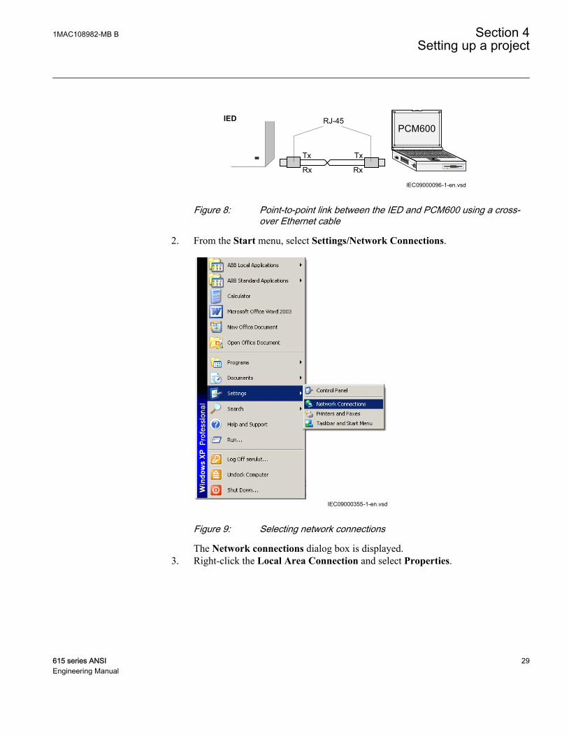
1. With an Ethernet cable, connect two physical Ethernet interfaces together withouta hub, router, bridge or switch in between.Use standard straight-through or crossover Ethernet cables. The minimum lengthfor the cable is 2 m. The connector type is RJ-45.
Section 4 1MAC108982-MB BSetting up a project
28 615 series ANSIEngineering Manual
IEC09000096-1-en.vsd
PCM600
Tx Tx
Rx Rx
RJ-45IED
IEC09000096 V1 EN
Figure 8: Point-to-point link between the IED and PCM600 using a cross-over Ethernet cable
2. From the Start menu, select Settings/Network Connections.
IEC09000355-1-en.vsdIEC09000355 V1 EN
Figure 9: Selecting network connections
The Network connections dialog box is displayed.3. Right-click the Local Area Connection and select Properties.
1MAC108982-MB B Section 4Setting up a project
615 series ANSI 29Engineering Manual

IEC09000356-1-en.vsdIEC09000356 V1 EN
Figure 10: Selecting local area connection properties
The Local Area Connection Properties dialog box is displayed.
IEC09000357-1-en.vsdIEC09000357 V1 EN
Figure 11: Local Area Connection Properties
4. From the list of configured components, select the Internet Protocol (TCP/IP)using this connection and click Properties.The Internet Protocol (TCP/IP) Properties dialog box is displayed.
Section 4 1MAC108982-MB BSetting up a project
30 615 series ANSIEngineering Manual

IEC09000358-1-en.vsdIEC09000358 V1 EN
Figure 12: TCP/IP settings
5. Click Obtain an IP address automatically and OK.6. Close all open dialog boxes and start PCM600.
4.4 Creating a new project
1. Start PCM600.2. To see the projects that are currently available in the PCM databases, select File/
Open/Manage Project on the menu bar.The Open/Manage Project window is displayed.
3. Click Projects on my computer.4. Click New Project.5. If there are currently projects or object tools open, a confirmation dialog box opens.
• Click Yes to close the open projects. A Create New Project dialog box opens.
GUID-F7D1FC0A-CFD5-4A4C-900C-E1F90DEDF3BF V1 EN
Figure 13: New Project dialog box
1MAC108982-MB B Section 4Setting up a project
615 series ANSI 31Engineering Manual

IEC09000375-1-en.vsdIEC09000375 V1 EN
Figure 14: Creating a new project
6. In the Project Name box, give a name for the project.
The project name must be unique.
7. Optionally, write a description of the project in the Description box.8. Click Create.
PCM600 sets up a new project that is listed under Projects on my computer.
4.5 Building the plant structure
Building a plant structure is useful when a complete grid with anessential number of IEDs has to be built.
1. Create a new plant structure.
Section 4 1MAC108982-MB BSetting up a project
32 615 series ANSIEngineering Manual

• In the Plant Structure view, right-click and select New/ Create fromTemplate.
• In the Plant Structure view, right-click and select New/ General andselect the element: either IED Group or Substation.
2. On the menu bar, click View/ Object Types.3. Select the needed elements and drag-and-drop them into the plant structure.
GUID-E856B2E2-8200-46FC-AA98-878F70C20A96-ANSI V1 EN
Figure 15: The start of a project with IEDs placed but not renamed
4. Rename each level in the structure by the names/identifications used in the grid.• Right-click the level and select Rename.• Rename the levels in the Object Properties view.
4.6 Inserting an IED
The context menu or the Object Types view shows the available 615 series IEDs thatcan be inserted, on the bay level, into the plant structure according to the installedconnectivity package.
It is possible to do various tasks in the plant structure.
1MAC108982-MB B Section 4Setting up a project
615 series ANSI 33Engineering Manual

• Insert an IED to offline mode or online mode• Import a template IED that is available in the template library as a .pcmt file• Import a preconfigured IED available as a *.pcmi file
From the plant structure it is possible to see whether the inserted IED isin the offline or online mode. A red cross in front of the IED symbolindicates an offline mode.
GUID-F9E16EA2-CDE7-4488-8CC5-5B66849C89FC V1 EN
Figure 16: Plant structure showing Bay1 in the online mode and Bay2 in theoffline mode
4.6.1 Inserting an IED in online modeWhen the IED is already connected to PCM600, PCM600 can read the order numberdirectly from the IED. It is possible to read the full configuration from the IED byusing the Read from IED function.To set up an IED online, the IED must be connected to PCM600.
1. In the Plant Structure view, right-click the bay and from the list that appears,select New and the IED application area, for example, Motor Protection IEDsand select the IED type to be inserted.
Section 4 1MAC108982-MB BSetting up a project
34 615 series ANSIEngineering Manual

GUID-AF88B4EA-85AF-43E8-AED7-D6EF9DD25B9C-ANSI V1 EN
Figure 17: Selecting the IED type
You can also drag-and-drop an IED from the Object Types viewto the bay level.
The Configuration Mode Selection Page dialog box opens.
1MAC108982-MB B Section 4Setting up a project
615 series ANSI 35Engineering Manual

GUID-C326AA0A-27ED-46DF-8B61-7484B8CB41F1-ANSI V1 EN
Figure 18: PCM600: Configuration mode selection
2. Select Online Configuration and click Next.The Communication protocol selection page is displayed.
Section 4 1MAC108982-MB BSetting up a project
36 615 series ANSIEngineering Manual

GUID-F8B3A98A-BD75-4E2D-B279-822A2504F1EE-ANSI V1 EN
Figure 19: PCM600: Communication protocol selection
3. In the IED protocol list, select the IED communication protocol and click Next.The Communication protocol page is displayed.
1MAC108982-MB B Section 4Setting up a project
615 series ANSI 37Engineering Manual

GUID-3FD49387-3726-4483-AD54-7FBC6D441805-ANSI V1 EN
Figure 20: PCM600: Communication port and IP address
4. In the Port list, select the port.• If the rear port is selected, insert the correct IP address (of the physical IED
to be configured) into the IP address box.
Communication configuration is now defined.
Section 4 1MAC108982-MB BSetting up a project
38 615 series ANSIEngineering Manual

GUID-FAC9B045-7D1C-4996-B038-F2DEEEFAD10A V1 EN
Figure 21: Communication configuration defined
5. Click Next in the Configuration Wizard.6. Click Scan to scan/read the order code of the IED.
The Order code detection page is displayed.
1MAC108982-MB B Section 4Setting up a project
615 series ANSI 39Engineering Manual

GUID-DAE10A3A-6821-4B06-B33A-670E22FC9834-ANSI V1 EN
Figure 22: PCM600: IED order code detection
7. Click Next.The Setup Complete Page dialog box shows the summary of the IED type,version, IP address and the selected order number.
Section 4 1MAC108982-MB BSetting up a project
40 615 series ANSIEngineering Manual

GUID-02789F3F-DD47-4CDB-86DE-F9258E01BF50-ANSI V1 EN
Figure 23: PCM600: IED setup complete
To cancel the insertion, click Cancel.
If an error is found on the Setup Complete Page, it is notpossible to go back and make modifications. If an error is
1MAC108982-MB B Section 4Setting up a project
615 series ANSI 41Engineering Manual

detected, cancel the insertion by clicking Cancel and insert theIED again.
8. Click Finish to confirm the configuration and conduct the insertion.9. From the Plant structure view, check that PCM600 has turned online the IED
that was inserted to the bay level.
You cannot scan data from the IED or proceed further if the IEDis not online or if the IP address is not correct.
4.6.2 Inserting an IED in offline modeWhen the IED is not available or is not connected to PCM600, engineering can be doneoff-line. The off-line configuration in PCM600 can be written to the IED later when itis connected.
Working in the offline mode has an advantage compared to online mode in that thepreparation for the configuration can be started even though the IED is not available.
1. In the Plant Structure view, right-click the bay and from the list that appears,select New and the IED application area, for example, Feeder IEDs.
2. Select the IED type to be inserted.
You can also drag-and-drop an IED from the Object Types viewto the bay level.
The Configuration Mode Selection Page dialog box opens.
Section 4 1MAC108982-MB BSetting up a project
42 615 series ANSIEngineering Manual

GUID-2A8CE4A6-1AA7-4129-A1B5-A739D4BCA4B7-ANSI V1 EN
Figure 24: PCM600: Configuration Mode Selection Wizard
3. Select Offline Configuration and click Next.Setting up an IED in the offline mode is similar as in the online mode; however,with offline mode it is not necessary to type the correct IP address in theCommunication port and IP address dialog box.
4. On the order code selection page, make right order code selections.5. Click Generate to generate the functions for the selected order code.
A “Function generation complete.” dialog box is shown. Click Close.6. Click Next on the Setup Complete Page that shows the summary of the IED
type, version, IP address and the selected order number.7. Click Finish to confirm the configuration and conduct the insertion.
1MAC108982-MB B Section 4Setting up a project
615 series ANSI 43Engineering Manual

4.6.3 Inserting an IED from the template directoryAn IED in the plant structure can be exported as a template (.pcmt file). The templatelibrary can be build up of all the exported IED templates.
It is also possible to insert an IED from the template library to create a new IED in theplant structure. After a template IED has been imported, the IP address, the name andthe technical key that corresponds to the physical IED have to be changed.
You can insert a template IED only when the bay is selected in theplant structure.
1. In the Plant structure view, select the bay, right-click and select New/ Createfrom template.The Create New Object from Template dialog box opens.
GUID-176DF09D-AF72-483A-B1FD-519D69345121 V1 EN
Figure 25: PCM600: selecting an IED from the template library
2. Select the IED from the list of available IEDs.3. Click the icon on the right column in the list of available templates.
The Template Properties dialog box opens.
Section 4 1MAC108982-MB BSetting up a project
44 615 series ANSIEngineering Manual
GUID-62DCC284-90D6-498A-A79A-25E884C61CC8-ANSI V1 EN
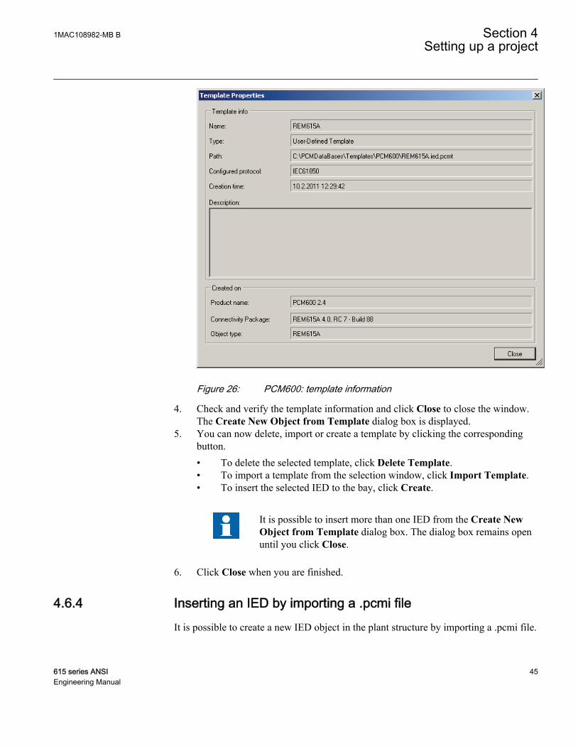
Figure 26: PCM600: template information
4. Check and verify the template information and click Close to close the window.The Create New Object from Template dialog box is displayed.
5. You can now delete, import or create a template by clicking the correspondingbutton.• To delete the selected template, click Delete Template.• To import a template from the selection window, click Import Template.• To insert the selected IED to the bay, click Create.
It is possible to insert more than one IED from the Create NewObject from Template dialog box. The dialog box remains openuntil you click Close.
6. Click Close when you are finished.
4.6.4 Inserting an IED by importing a .pcmi fileIt is possible to create a new IED object in the plant structure by importing a .pcmi file.
1MAC108982-MB B Section 4Setting up a project
615 series ANSI 45Engineering Manual

A .pcmi file can only be selected when the bay is selected in the plantstructure.
1. In the Plant Structure view, right-click the IED and from the list that appears,select Export.
GUID-9C892D93-9D92-4DB7-A576-B20716E42895 V1 EN
Figure 27: Exporting IED configuration
2. Write a name in the File name text box in the Export dialog box and select thefile type as .pcmi.
Section 4 1MAC108982-MB BSetting up a project
46 615 series ANSIEngineering Manual

GUID-970C33D9-9A83-4C83-AE3E-F237BEEF4F7A-ANSI V1 EN
Figure 28: Export dialog box
3. Click Save.A .pcmi file is created in the selected path.
4. In the Plant Structure view, right-click the bay and from the list that appears,select Import.
A .pcmi file can be imported only when the bay is selected in theplant structure.
1MAC108982-MB B Section 4Setting up a project
615 series ANSI 47Engineering Manual

GUID-187F89B8-CF8B-457B-A6C2-09E3FF34E929-ANSI V1 EN
Figure 29: Importing IED configuration
5. Select the .pcmi file to be imported and click Open.After importing, the IED object is created in the plant structure.
After the .pcmi file has been imported, the IP address, the name and the technical keythat corresponds to the physical IED have to be changed.
4.7 Setting the IED IP address in a project
The IP address and subnet mask of the IED object in PCM600 must match the frontand rear port of the physical IED to which the PC is connected. The IP address of thephysical IED can only be set via the LHMI and cannot be set from PCM600. The PCand IED may need to be on the same subnet.
Section 4 1MAC108982-MB BSetting up a project
48 615 series ANSIEngineering Manual

In PCM600, there are two alternatives to set the IP address of an IED object.
• On the first page of the wizard when including a new IED into a project.• In the IP address box of the IED's Object Properties dialog box.
GUID-0C8D23CA-5BB5-4D36-9B11-245B5465D9E1-ANSI V1 EN
Figure 30: Alternative 1: setting the IP address on the first wizard page
1MAC108982-MB B Section 4Setting up a project
615 series ANSI 49Engineering Manual
GUID-B4B71E12-25CB-4B8B-8F9A-90131BD68E4D V1 EN
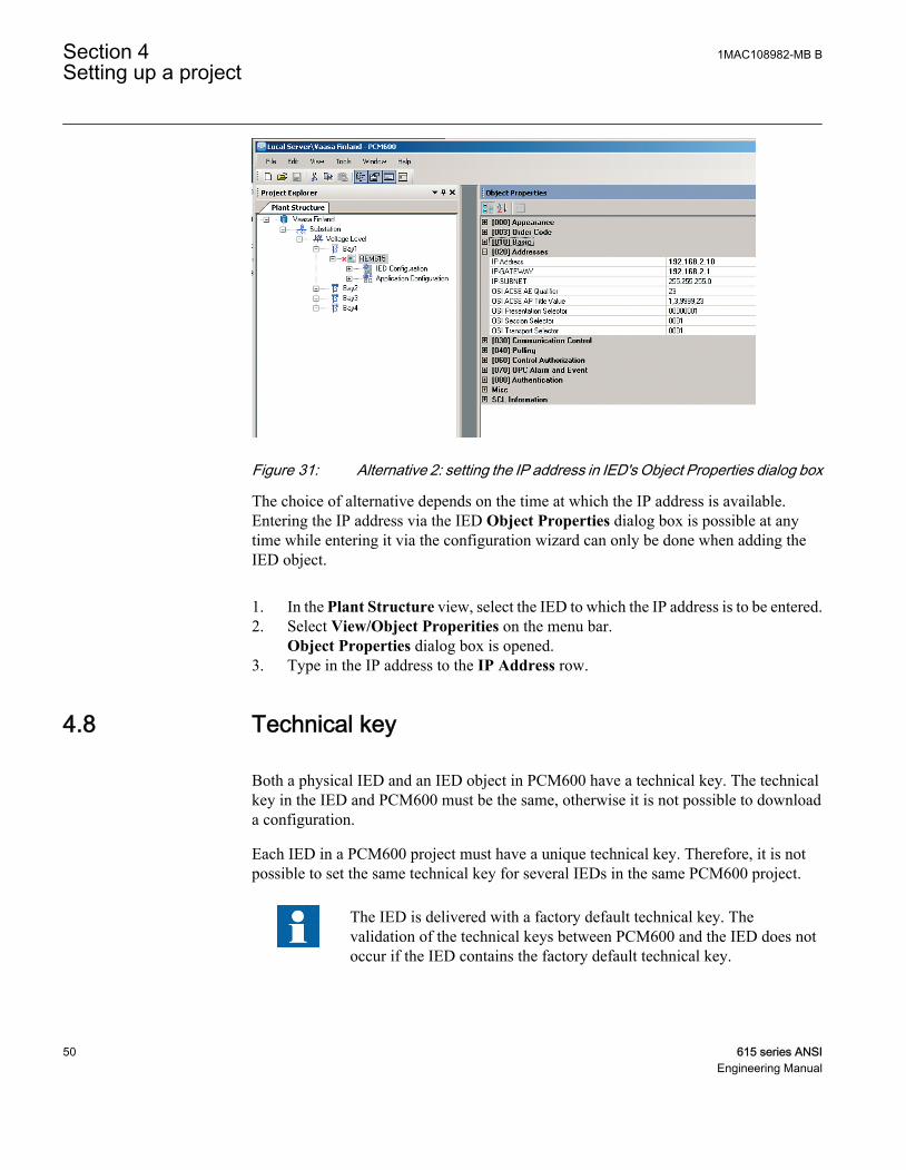
Figure 31: Alternative 2: setting the IP address in IED's Object Properties dialog box
The choice of alternative depends on the time at which the IP address is available.Entering the IP address via the IED Object Properties dialog box is possible at anytime while entering it via the configuration wizard can only be done when adding theIED object.
1. In the Plant Structure view, select the IED to which the IP address is to be entered.2. Select View/Object Properities on the menu bar.
Object Properties dialog box is opened.3. Type in the IP address to the IP Address row.
4.8 Technical key
Both a physical IED and an IED object in PCM600 have a technical key. The technicalkey in the IED and PCM600 must be the same, otherwise it is not possible to downloada configuration.
Each IED in a PCM600 project must have a unique technical key. Therefore, it is notpossible to set the same technical key for several IEDs in the same PCM600 project.
The IED is delivered with a factory default technical key. Thevalidation of the technical keys between PCM600 and the IED does notoccur if the IED contains the factory default technical key.
Section 4 1MAC108982-MB BSetting up a project
50 615 series ANSIEngineering Manual

The technical key property in PCM600 corresponds to the IED nameattribute in SCL files. Avoid changing the IED name attribute outsidePCM600, because data in PCM600 may get lost when importing theSCL files.
The technical key must be the same for the communication between the IED andPCM600. The technical key can be read from the IED and updated to PCM600, or thePCM600 technical key can be written to the IED. Alternatively, a separate technicalkey can be defined.
When writing a configuration to the IED, PCM600 checks for a mismatch between theIED object and the physical IED technical key.
GUID-EF8A07F6-C6D1-4AA8-BDAD-A5F29F33389A V1 EN
Figure 32: Reboot suggestion
Ensure that the IED object in PCM600 has the same IP address as thephysical IED that is intended to be connected through the technical keyconcept.
You can change the technical key for an IED object in the ObjectProperties dialog box in PCM600.
4.8.1 IEC 61850 naming conventions to identify an IEDThe IEC 61850 naming conventions to identify an IED are only valid when the IEC61850 standard is used for station bus communication. According to the IEC 61850–6clause 8.4, the SCL model allows two kinds of project designations in the objectproperties: a technical key and a user-oriented textual designation.
Technical key is used in engineering drawings and for signal identifications. This iscontained in the attribute name as an identification of each object. If the value is usedas a reference to an object, it is contained in an attribute name starting with a stringdenoting the reference target object type and ending with the string Name. The
1MAC108982-MB B Section 4Setting up a project
615 series ANSI 51Engineering Manual

technical key is used within SCL for referencing to other objects. Note that the name isa relative identification within a hierarchy of objects.
User-oriented textual designation is contained in the desc attribute. Attributes are notallowed to contain carriage return, line feed, tab, greater than, less than, double quotesor ampersand characters. The semantics of desc must also be relative within an objecthierarchy.
PCM600 takes care of the two possibilities. The two possible signal designations areavailable per object in the object properties for all hierarchical levels beginning withthe station as the highest level.
The technical key is automatically generated based on the rules and type specificationsof IEC 61346 and the extended definitions assigned for substations by a technicalcommittee. The technical key is shown in the Object Properties dialog box underSCL Technical Key or Technical Key.
• The station is predefined by “AA1" where 1 is the index. To get the real stationname that is used, it is possible to rename the SCL Technical Key for the stationas the name used by the project. To minimize the word length, take a short formbecause this name is used also in the transmitted messages to identify the events,for example.
• The voltage level. In the example it is 20 kV and J1 is selected from the list belowSCL Technical Key in the Object Properties dialog box.
• The bay and the IED are appended with the coding defined in the IEC 61346standard and the substation definition lists. In the example, Bay SCL TechnicalKey part is Q01 and IED is A1.
The user-oriented textual designation is visible in the Plant structure view for eachobject. It is the name given by default or changed by using the Rename function.
Section 4 1MAC108982-MB BSetting up a project
52 615 series ANSIEngineering Manual

GUID-81D555F9-0F22-4112-BF6D-48F2A3376612-ANSI V1 EN
Figure 33: PCM600: IEC 61850 signal designation concept
The created technical key for the full path name of the IED would be: AA1J1Q01A1.
• AA1 = substation in the project• J1 = voltage level from 20 to 30 kV• Q01 = the first bay in the voltage level• A1 = first IED in the bay Q01
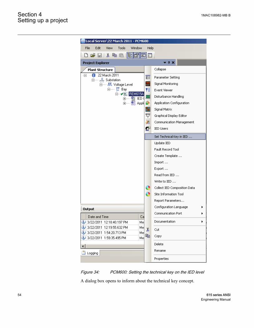
4.8.2 Setting the technical key
1. Select the IED in the Plant Structure view and right-click.2. From the list that opens, select Set Technical Key in IED.
1MAC108982-MB B Section 4Setting up a project
615 series ANSI 53Engineering Manual
GUID-EE8F635B-1895-4117-A756-F80FA9027037-ANSI V1 EN
Figure 34: PCM600: Setting the technical key on the IED level
A dialog box opens to inform about the technical key concept.
Section 4 1MAC108982-MB BSetting up a project
54 615 series ANSIEngineering Manual

GUID-6A512EF8-5BDF-4B4A-A721-8152DB9D51A1 V1 EN
Figure 35: Techical key information
3. Click OK.The technical key is read from the IED and the Set Technical Key dialog box opens.
GUID-177E6088-50E3-4A18-83E6-9777AEACB3C1 V1 EN
Figure 36: Setting the technical key
4. In Set Technical Key dialog box, select the techical key to be used. There arethree alternatives.• Use the existing technical key in the IED• Use the existing technical key defined for the IED object in PCM600• Set a user-defined technical key, which changes the technical key for both
the physical IED and IED object in PCM600
1MAC108982-MB B Section 4Setting up a project
615 series ANSI 55Engineering Manual

Do not use a technical key that has more than 10 characters.
5. Click OK to confirm the selection.
It is not possible to set a user-defined name or select theTechnical key in IED if the value is the same as already given toanother IED object in the PCM600 project. An error message isdisplayed if this happens.
4.9 COM600 project
The 615 series connectivity package has support for SAB600. A 615 series IED isimported as a 615 series device. It is also possible to import a full PCM600 projectincluding several 615 series devices to SAB600. In this case, PCM600 projectinformation is imported to SAB600 using a SCD file.
The 615 series device supports several functions in COM600.
• Controlling the switchgear• Monitoring the measured values• Reading digital fault recordings• Setting parameters
4.9.1 Importing a 615 series IED in a COM600 project
1. Create a PCM600 project including several 615 devices.
Section 4 1MAC108982-MB BSetting up a project
56 615 series ANSIEngineering Manual

GUID-01F6FEB6-B57B-4A56-939B-46750205D914 V1 EN
Figure 37: Creating a PCM600 project including several 615 devices
2. Export the SCD file from PCM600.In the Plant structure view, select the substation, right-click and select Export.
1MAC108982-MB B Section 4Setting up a project
615 series ANSI 57Engineering Manual

IEC09000687-1-en.vsdIEC09000687 V1 EN
Figure 38: Exporting SCD file from PCM600 and importing it to SAB600
3. Import the SCD configuration into the SAB600 project.In the Project Explorer view, right-click the IEC61850 OPC Server object andselect Import.
Section 4 1MAC108982-MB BSetting up a project
58 615 series ANSIEngineering Manual

GUID-70E8B187-FADA-4657-9BC7-223FDA7374ED V1 EN
Figure 39: Importing the SCD configuration into the SAB600 project
4. In the SCL Import view, click Select File to select the SCD file exported fromPCM600.
1MAC108982-MB B Section 4Setting up a project
615 series ANSI 59Engineering Manual

GUID-6F47B4AD-B956-4F77-A6A2-DE6F4A71D607 V1 EN
Figure 40: Creating a new 615 series device into SAB600 project
5. Check the default settings in the SCL Import view and change the settings ifthey are not suitable.The default settings in the SCL Import dialog should be OK in most cases.
6. Click Import to import the SCD file.7. Check the IP address on the IEC61850 subnetwork and change it if needed.
When the SCD file is direcly exported from PCM600, it will use the IP address ofthe PCM600 computer, not the COM600.
The communication towards the 615 series devices is now ready. For information onhow to finalize the single-line diagram and enable parameter setting through COM600HMI, see COM600 documentation.
4.10 Using the Web HMI
WHMI is enabled by default. Log in with the proper user rights to use the WHMI.
1. To enable the WHMI, select Main menu/Configuration/HMI/Web HMI modevia the LHMI.
2. Reboot the IED for the change to take effect.
Section 4 1MAC108982-MB BSetting up a project
60 615 series ANSIEngineering Manual

For more information on the WHMI, see the operation manual.
4.11 IED User Management
IED user authorization is disabled by default and can be enabled at Main Menu/Configuration/Authorization in local HMI or WHMI. IED user passwords can bechanged in local HMI and using IED User Management tool in PCM600.
GUID-FC9D4AB3-C472-4BDB-B64B-DEE4FEACC4FA V1 EN
Figure 41: Change password using IED User Management tool
In case remote authentication has been enabled, the user has to make followingchanges in PCM600 in order to get the communication between the IED and PCM600to work:
Table 2: Object properties to change
Object Properties field ValueIs Authentication Disabled False
Is Password used True
Password Write the correct password
1MAC108982-MB B Section 4Setting up a project
615 series ANSI 61Engineering Manual

GUID-D0853D4E-D594-454A-9299-997ADF3E0896 V1 EN
Figure 42: Object properties
When communicating with IED using PCM tools and having IED authenticationenabled, the user will be prompted for IED user name and password. When setting thetechnical key, the user has to give the username and password twice.
GUID-310E1587-D064-4823-9329-12163E0C9306 V1 EN
Figure 43: User login
Section 4 1MAC108982-MB BSetting up a project
62 615 series ANSIEngineering Manual

If PCM authentication has been enabled in PCM System Settings, anIED user can be linked to the PCM user being used by checking theRemember me flag in the IED Login dialog. After that the IED Logindialog will not be needed at tool communication in the future, sincelogging into PCM will then also provide for IED authenticationcredentials.
Audit trails (IED login, logoff events) can be monitored by using theEvent Viewer tool. By default, the audit trails are not shown in theEvent Viewer tool. To view them, change the defaultADMINISTRATOR IED password by using the IED UserManagement tool, and log in as ADMINISTRATOR IED user whenopening the Event Viewer tool.
1MAC108982-MB B Section 4Setting up a project
615 series ANSI 63Engineering Manual

64
Section 5 Protection and control engineering
5.1 Application Configuration tool
Application Configuration tool is used to modify an application configuration for anIED and is based on IEC 61131-3 Function Block Diagrams.
The function blocks are dedicated to different functions.
• Control related functions• Protection related functions• Monitoring functions• Communication
For more information on the function blocks, see the technical manual.
Most function blocks are mapped as logical nodes according to the IEC 61850standard. See the IEC 61850 parameter list for more information.
If a function block is removed with Application Configuration, thefunction related data disappears from the menus as well as from theIEC 61850 data model, with the exception of some basic functionblocks, which are mandatory and thus cannot be removed from the IEDconfiguration by removing them from the Application Configuration.
Other function blocks are not mapped as logical nodes; for example, logical gates.
The basic features of Application Configuration tool include the ability to organize aconfiguration into several MainApplications as well as providing different applicationprogramming features.
• Organize an application configuration• Organize an application configuration into a number of logical parts
(MainApplication)• Organize a MainApplication over a number of pages
• Features for programming an application configuration
1MAC108982-MB B Section 5Protection and control engineering
615 series ANSI 65Engineering Manual

• Insert function blocks, make connections and create variables• Include the hardware I/O channels directly to the application configuration• Calculate the execution order automatically by clicking Calculate execution
order on the toolbar.• Document the application configuration: such as, make printouts• Save application configurations as templates in an application library to
reuse them in other IEDs• Validate the application configuration during the configuration process on
demand and while writing the application configuration to the IED
For instructions on how to perform the different tasks in PCM600, seePCM600 online help.
5.1.1 Function blocksFunction blocks are the main elements of an application configuration. They aredesigned for a various number of functions and organized into groups by type. Thedifferent function block types are shown in the Object Types view. Function blockdata can be modified with the Application Configuration tool.
• Set user-defined names for function blocks and signals marked with blue text.
Signals that have a user-defined name created with the ApplicationConfiguration tool are only visible in the Parameter Setting tool ifthe IED configuration is written to the IED and read back toPCM600. Otherwise, the default signal name is shown in theParameter Setting tool.
If possible, set the user-defined name to a signal before connectingthe signal to other function blocks.
• Set IEC 61850, ANSI or IEC 60617 symbol standard.• Set IEC or/and ANSI naming style.• Lock function blocks.• Set visibility for execution order, cycle time and instance number.• Manage signals; for example, hide, show and rearrange.• Invert Boolean inputs and outputs.
Section 5 1MAC108982-MB BProtection and control engineering
66 615 series ANSIEngineering Manual

1 2 3 4 5 6 7
8 9 11 12 13 14 1510
GUID-805CB8E5-0BF2-409D-802C-57DC95659075 V1 EN
Figure 44: Application Configuration tool: function block overview
1. Connection(s)2. User-defined function block name3. Function block, selected (red)4. Function block name5. Function block, locked (red)6. Hardware, binary output channel7. Hardware, programmable LED8. Hardware, binary input channel9. Hardware, analog input channel10. User-defined signal name11. User-defined input variable12. Execution order13. Cycle time14. Instance number15. Signal description note
5.1.2 Signals and signal managementFunction block has a set of input and output signals. The placement of function blocksignals is from left to right. Input signals are placed on the left and output signals onthe right.
Function blocks can contain more signals than needed in that application part. Unusedsignals can be hidden to get a clear picture.
Signals are located up and down on both sides of the middle position. When there isspace left, some signals may be moved up or down for better visibility and connectionrouting.
1MAC108982-MB B Section 5Protection and control engineering
615 series ANSI 67Engineering Manual
Boolean input and output signals may need to be inverted to fulfil the logic. TheApplication Configuration tool supports the adding of inversion logic to a binary signal.
The input signal on glue logic function blocks can only be inverted if aglue logic function block with lower execution order in the same cycletime is available. Similarly, the output signal can only be inverted if aglue logic function block with higher execution order in the same cycletime is available. Up to two input signals and two output signals can beinverted for glue logic blocks in the same cycle time.
All input signals have a default value that is used when not connected.
5.1.3 Function block execution parametersThree function block execution parameters have an influence on the runtime executionof the function block within the application configuration.
• Execution order• Cycle time• Instance number
Each time a new function block is selected, these parameters must be selected from thelists in the Application Configuration tool. Depending on the function block type,some of the three parameters are selectable and some not. The cycle time may bepredefined to one value. The instance number is a counter for the total possible numberof function blocks of that type used within the application configuration.
The Execution Order and Instance Number are a combination that is predefinedwithin a product. It is possible to select a pair out of the list.
Section 5 1MAC108982-MB BProtection and control engineering
68 615 series ANSIEngineering Manual

GUID-4129D712-CD43-4729-8FE4-27FFE758D151-ANSI V1 EN
Figure 45: Application Configuration tool: an example of function blockorganization parameters
The Cycle Time is automatically set to 2.5 ms (50 Hz) or to 2.083 ms (60 Hz) and itcannot be modified. Depending on the function block type and the 615 series product,only one or both possibilities may be available.
To automatically calculate the execution order, click CalculateExecution Order on the tool bar.
5.1.4 Execution order and feedback loopsWith the Application Configuration tool it is possible to draw multi-layer configurationlogic that contains feedback loops. The execution order of logic functions is calculatedautomatically in the Application Configuration tool, but the execution order can be setmanually also. If the automatically calculated value causes the function to be executedone task cycle time after the other logic functions in the same loop, the execution ordernumber can be set manually to prevent delays, for example, in output activation.
The following example shows a simple situation where the execution order causes onecycle time delay if the NOT port is executed in the order determined by the automaticcalculation.
1MAC108982-MB B Section 5Protection and control engineering
615 series ANSI 69Engineering Manual

GUID-F8162182-FF21-467A-AEB9-23284CB3FABD V1 EN
Figure 46: Feedback loop situation with automatically calculated execution orders
By setting a smaller execution number than in the AND port to where the NOT port isconnected, it is possible to fix the execution order of all functions in a loop so that theyare handled in the same task.
GUID-0C12B88A-0ABE-49DE-9A44-05D213D04922 V1 EN
Figure 47: Feedback loop situation with manually fixed execution order for NOT port
5.1.5 Configuration parametersConfiguration parameters can be viewed and set with the Parameter Setting tool.
5.1.6 Connections and variablesA connection is the link or "wire" between function block outputs and inputs.
There are rules and methods for making connections.
• Drag a line between two signals• Link two signals by using variables
Section 5 1MAC108982-MB BProtection and control engineering
70 615 series ANSIEngineering Manual

It is possible to search and replace variable names in ApplicationConfiguration tool.
Connect the variables to a destination, for example to a function blockor a hardware output channel. The connectivity package automaticallyremoves the orphan variables which are not connected to any destination.
Connection validationA connection is only useful or even possible between two signals of the same baseattribute type.
GUID-720C9C93-AB56-4AEB-AF72-7E136E62A87F-ANSI V1 EN
Figure 48: Application Configuration tool: an error message of a signal mismatchfor a connection
5.1.7 Hardware channelsHardware channels can only be connected to a function block input or output. Ahardware connection can be established with the Application Configuration tool orSignal Matrix tool.
When a hardware channel is connected, a graphical symbol appears in the ApplicationConfiguration tool. The connection is also displayed in the Signal Matrix tool with across mark. Hardware channels are always visible in the Signal Matrix tool.
1MAC108982-MB B Section 5Protection and control engineering
615 series ANSI 71Engineering Manual

GUID-40339889-3049-4C50-BA8F-8C3EB9A54C4D V1 EN
Figure 49: Application Configuration tool: HW signal channels
There are three types of supported hardware channels.
• Binary input channels• Binary output channels• Analog input channels
Hardware input channel can be used as often as needed. A hardware binary outputchannel is taken from the list of available channels when a new channel is requested.This prevents using the same hardware binary output channel twice.
5.1.8 ValidationValidation checks the application configuration for errors based on the rules thatgovern the creation of the application at three different times.
• During the logic creation, while making a connection or placing a function block• On demand by starting the validation• When writing the application configuration to the IED
5.1.8.1 Validation when creating an application configuration
Validation is made when creating the application configuration.
Section 5 1MAC108982-MB BProtection and control engineering
72 615 series ANSIEngineering Manual

• A connection between two input or two output signals is not possible• A connection between two different data types is not possible: for example, from a
binary output to an analog input
5.1.8.2 Validation on demand
The validity of an application configuration can be checked by clicking ValidateConfiguration in the toolbar. The Application Configuration tool checks theapplication configuration for formal correctness. The found problems are divided intowarnings and errors.
• Warnings, marked with a yellow warning icon• Example: a variable connected to an output signal that is not connected• Example: if the user connects an output from a higher execution order
function to inputs of lower execution order function• Errors, marked with a red circle with a cross
• Example: unconnected hardware output
Warnings do not prevent writing to the IED. However, errors must be corrected beforewriting the application configuration to the IED. The application configuration can besaved and the Application Configuration tool can be closed with open errors, but notwritten to the IED.
These problems are listed in the Output view under the Application Configurationtab. Double-clicking the error or warning row navigates to the MainApplication/Page/ Area, where the problem was identified.
1MAC108982-MB B Section 5Protection and control engineering
615 series ANSI 73Engineering Manual

GUID-F33821B8-2643-4092-85DB-9C732A95C77E V1 EN
Figure 50: Application Configuration tool: validation on demand
5.1.8.3 Validation when writing to the IED
When writing the application configuration to the IED, an automatic validation isperformed. The validation is the same as the manually demanded validation. Errorsabort the writing.
5.2 Parameter Setting tool
Configuration parameters and settings parameters can be changed with LHMI, WHMIor with the Parameter Setting tool in PCM600.
Some parameters are only visible in the Parameter Setting tool andsome only in LHMI.
A common writing from PCM600 to the IED, where parameters arechanged in the Parameter Setting tool, overwrites any parameterchanges made locally with LHMI.
All variables listed and displayed in the parameter list can be sorted into two groups.
Section 5 1MAC108982-MB BProtection and control engineering
74 615 series ANSIEngineering Manual

• Configuration parameters• Setting parameters
5.2.1 Configuration parameterConfiguration parameter specifies the operation mode of an application function or ofthe IED. These are basic configurations that are normally configured only once andthen not modified again. The IED configures itself during startup according to thegiven configuration parameter values.
5.2.2 Setting parameterSetting parameter (short form: “setting”) is a parameter that can be changed in the IEDat runtime.
5.2.3 Setting groupNearly all settings used by the IED for protection application functions are organizedinto a group of settings. Up to six setting groups can be configured with different values.
The IED supports the selection of a setting group at runtime.
5.2.4 IED parameter organizationThe organization of parameters into a tree structure becomes visible in the PlantStructure by expanding the setting tree.
5.3 Signal Matrix tool
The Signal Matrix tool is used to make cross-references between the physical I/Osignals and function blocks and for the GOOSE signal input engineering.
The Signal Matrix tool cannot be used for adding or removing functionblocks, for example, GOOSE receive function blocks. The ApplicationConfiguration tool is used for this kind of operations.
1MAC108982-MB B Section 5Protection and control engineering
615 series ANSI 75Engineering Manual

BIO
BIO
RTD
FBs
BinaryInputs
BinaryOutputs
AnalogInputs
HardwareIO interfaces
Signal MatrixFBs
IEC 61850 GOOSERSV(input side)GOOSE
FBs
FBs
GOOSERSV(output side)
Functions
FBs
FBs
GUID-50BC48B0-574F-4DD8-9678-67A0954D1C13 V1 EN
Figure 51: Signal Matrix tool: operation principles
A binary input channel can be connected to one or more function block inputs. If it isactivated from more than one function block output, the glue logic has to be used. Gluelogic means inserting a logical gate (OR and AND blocks) between the function blocksand the binary output channel. This can be engineered with the Signal Matrix tool.
A binary output channel can only be activated from one function block output. If it isactivated from more than one function block output, the glue logic has to be used.
Section 5 1MAC108982-MB BProtection and control engineering
76 615 series ANSIEngineering Manual

Glue logic means inserting a logical gate (OR and AND blocks) between the functionblocks and the binary output channel. This can be engineered with the Signal Matrix tool.
Connections made with the Signal Matrix tool are automatically alsoshown in the Application Configuration tool.
GUID-D0C99F05-64B1-487F-A713-3C9A495B27AC-ANSI V1 EN
Figure 52: Signal Matrix tool: a connection between binary input channels tobinary input signals
Depending on the IED capability, the Signal Matrix tool has a separate sheet for eachpossible combination.
The possible sheets are:
• Binary inputs• Binary outputs• Analog inputs• Functions• GOOSE
1MAC108982-MB B Section 5Protection and control engineering
615 series ANSI 77Engineering Manual

5.4 Load Profile tool
Load Profile tool is used for reading load profile records from an IED, clearing oldrecords and viewing records via an external COMTRADE viewer. The default viewerincluded with PCM600 is Wavewin, but a third party viewer can be used.
5.4.1 Opening and closing Load Profile tool• To open the Load Profile tool, click Load Profile Tool on the context menu of an
IED node inside the PCM600 project tree.
Section 5 1MAC108982-MB BProtection and control engineering
78 615 series ANSIEngineering Manual

GUID-F8120497-31C8-4F8B-BBE8-D1338CF4E4E6 V1 EN
Figure 53: Opening the Load Profile tool
• To close the Load Profile tool, click the Close button in the tool.The Load Profile tool runs in the same process as PCM600 but in a separatewindow. Multiple instances of the tool can be run at the same time. Any open toolinstances are closed without confirmation when PCM600 is closed.
1MAC108982-MB B Section 5Protection and control engineering
615 series ANSI 79Engineering Manual

GUID-4B275369-045F-4407-89A2-44071839699D V1 EN
Figure 54: Load Profile tool
By default, the Load Profile tool uses the \PCMDataBases\LPR directory as asaving target directory.
Section 5 1MAC108982-MB BProtection and control engineering
80 615 series ANSIEngineering Manual

5.4.2 Load Profile tool user interface
GUID-4B275369-045F-4407-89A2-44071839699D V1 EN
Figure 55: Load Profile tool interface
Table 3: Available actions on the user interface
Action DescriptionLocal Path Default local path (C:\PCMDataBases\LPR) is the location from which the records
are shown on the Load Profile tool. It is also the default path for saving records.Local Path field also allows the user to change the target location where the recordsare saved. The grid of the Load Profile tool shows only the records in the default localpath including unsaved records in the temp path (C:\Temp\Load\Profile Tool) ifthere are any. Therefore changing the default local path allows the user to saverecords at the specified location on the local machine but the user is not be able tosee those records in the grid of the Load Profile tool.
Load Clicking the Load button downloads all available records from C:\LDP\COMTRADEdirectory in the IED to a temporary folder C:\Temp\LoadProfileTool on the localmachine. In this temporary folder, the target file name is constant, and loading againoverwrites the file. An unsaved record is deleted when the tool is closed.
Save Clicking the Save button moves the records to the default or specified local path, Loadtransfers the records to a temporary folder. Each load profile record comprises twofiles with file extensions .dat and .cfg.Clicking Save adds a time stamp to the file names and moves the two files pertainingto the record to the default or specified folder. Saving another record creates a newrecord in addition to the old ones.
Clear Clicking the Clear button clears record from either the Load Profile tool or IED or both.Before deleting the records, a confirmation dialog box is shown.
Table continues on next page
1MAC108982-MB B Section 5Protection and control engineering
615 series ANSI 81Engineering Manual

Action DescriptionOpen Select any record and click Open to view the record in Wavewin, provided that this
external software is installed. Additionally, any record row can be double-clicked toview that record.
Sort To sort the record rows by any column click a column header.
Close Clicking the Close button closes this instance of the tool. Any open instance is finallyclosed when the whole PCM600 is closed.
File All the actions are also available on the tool through File drop-down menu.
5.4.3 Information fieldsThe IP box shows the IP address of the selected IED and the Local Path box showsthe selected location for reading or viewing records.
In the record grid, the name, creation time, modification time and size of each recordare shown. The times and dates shown in the grid are the times when the files havebeen read rather than the original date stamps in the IED.
GUID-82E7859C-3C2B-43F1-83C3-7AA8087C569C V1 EN
Figure 56: Information fields
5.5 Fault Record tool
The Fault Record tool is used for reading the fault records from the IED and it isincluded in the connectivity packages. The tool makes analyzing the fault recordseasier by showing them separately in their own user control components. It alsoincludes save, copy and clear functions where all the fault records are saved or copiedin text format for later viewing or cleared from the IED or the tool.
5.5.1 Opening and closing Fault Record tool• To open the Fault Record tool, click Fault Record Tool on the context menu of an
IED node inside the PCM600 project tree.
Section 5 1MAC108982-MB BProtection and control engineering
82 615 series ANSIEngineering Manual

GUID-06441245-E6DA-4C9F-9363-26CE8D521CB2 V1 EN
Figure 57: Opening the Fault Record tool
• To close the Fault Record tool, click the Close button in the tool.The Fault Record tool runs in the same process as PCM600 but in a separatewindow. Multiple instances of the tool can be run at the same time. Any open toolinstances are closed without confirmation when PCM600 is closed.
Fault Record tool is a connectivity package tool. The main functionality is divided intothree parts – reading the fault record parameters from the IED, displaying their names,values and units on the user interface and saving them to a text file. It is also possible
1MAC108982-MB B Section 5Protection and control engineering
615 series ANSI 83Engineering Manual

to clear all the fault records from both the tool and the IED and copy the fault recordseither individually or all at once and paste them to a word processor.
5.5.2 Fault Record tool interfaceTable 4: Available actions on the user interface
Action DescriptionRead Clicking the Read button reads all available fault records from the IED into the tool.
User has the option to read 1 fault record, 20 fault records or all fault records. TheRead button opens up a progress bar to indicate an ongoing read operation.Click the Cancel button on the Read progress bar to cancel the read operation. Onoperation completion, the available fault records are shown in the record grid.Click the + icon to expand and view record details.
Save Click Save to save the fault records on the local machine as .txt file.
Clear Record can be cleared from either the Fault record tool or the IED or both. Beforedeleting the records, a confirmation dialog box is shown.
Close Clicking the Close button closes this instance of the Fault Record tool. Any openinstance is finally closed when the whole PCM600 is closed.
File File menu for Save and Exit actions.
Edit Copy All in the Edit menu allows to copy all the fault records which can then bepasted to a word processor and saved on the local machine without having to savethe records as a .txt file.Additionally the user can select any particular fault record and right-click to copy theselected record.
Section 5 1MAC108982-MB BProtection and control engineering
84 615 series ANSIEngineering Manual

Section 6 LHMI engineering
For information on LED operation modes supported by 615 series, seetechnical manual.
6.1 Single-line diagram engineering
A single-line diagram of the IED can be designed by using the Graphical DisplayEditor tool of PCM600. The single-line diagram is modelled according to the IEC61850 standard in the Graphical Display Editor.
6.1.1 Diagrams in Graphical Display EditorThe Graphical Display Editor is used for various tasks.
• HMI display raster layouts• Adding static text• Adding measurands• Adding busbars• Adding symbols onto display page• Drawing lines (creating a link)
1MAC108982-MB B Section 6LHMI engineering
615 series ANSI 85Engineering Manual

HMI display page
Symbol library window
IED HMI display window
GUID-8843160D-28CC-46D5-8045-445FAAB335B9-ANSI V1 EN
Figure 58: Graphical Display Editor: an active view
The Graphical Display Editor has a fixed symbol library window on the left side of theview. The presentation is empty when no page exists for the IED. A default single-linediagram presentation is displayed if standard configurations are used.
6.1.1.1 Display window and sequence order
There are rules for handling the HMI pages.
• IED supports one bay with one single-line diagram.• Measurements and the single-line diagram can be displayed on the page in any
possible order and placement.• All symbol objects, for example apparatus and measurement, on the HMI page
must be linked to the correct function block in the application configuration inorder to present the correct process values.
Section 6 1MAC108982-MB BLHMI engineering
86 615 series ANSIEngineering Manual

6.1.1.2 Symbol library
The Symbol Library view contains panes that include drawing symbols or elementsfor creating a single-line diagram, measurements and texts onto a page. Panes can beopened by clicking the name bar of the selected element.
The library shows the symbols either in the ANSI standard or IEC standard. Thestandard is selected from the list located on top of the window.
When changing to another library standard, Graphical Display Editor changes thesymbols according to the selected new standard and redraws the single-line diagram inthe window.
To change the symbol format used in the IED, select Main menu/Configuration/HMI/SLD symbol format and choose IEC or ANSI.
To become familiar with the available symbols, select the differentpanes and their symbols.
6.1.1.3 Supported single-line diagram symbols
Table 5: Single-line diagram symbols
Description IEC representation ANSI representationCircuit breaker — Intermediate position
Circuit breaker – Open position
Circuit breaker – Closed position
Circuit breaker – Bad (faulty) position
Disconnector – Intermediate position
Disconnector – Open position
Table continues on next page
1MAC108982-MB B Section 6LHMI engineering
615 series ANSI 87Engineering Manual

Description IEC representation ANSI representationDisconnector – Closed position
Disconnector – Bad (faulty) position
Truck – Intermediate position
Truck – Open position
Truck – Closed position
Truck – Bad (faulty) position
In-feeder
Out-feeder
Current transformer
Voltage transformer
Ground symbol
Motor
Generator
Power transformer with two windings
Section 6 1MAC108982-MB BLHMI engineering
88 615 series ANSIEngineering Manual

6.1.1.4 HMI display raster layout and text font selection
The raster on the page changes from symbol presentation to text presentation when atext object is selected and vice versa.
The text can be presented in UniCode characters (6 x 12 pixel).
The total size of the presented white area (page) represents the visible part of theLHMI display without the header line.
The visible display for a single-line diagram is organized in a raster of 9 x 7 (columnsx rows). Each symbol (presented in 15 x 15 pixels) included in the drag-and-dropmethod must be dropped into a raster box.
The description text for an apparatus object can be placed in all four directions aroundthe symbol. The description is part of the apparatus object. It is possible to place thesymbols without the assistance of Snap to Grid and manually change the positioncoordinates.
6.1.1.5 Text handling
The display switches when text is selected in a display of 22 x 9 (columns x rows).One display box is the placeholder for one character. A text element must be placed inthe position of the display.
The name and the unit of a measurement or text symbol can be changedby double-clicking the symbol or via the Object Properties view.
Selecting and toggling Show Texts using the IED fonts can be used to preview the single-line diagram to see how it will be presented in the real HMI display.
6.1.1.6 Adding static text
1. Place a Static Text object into a raster box by dragging-and-dropping.
1MAC108982-MB B Section 6LHMI engineering
615 series ANSI 89Engineering Manual

GUID-4D3D2FE7-B26C-4177-BE09-CE3CEBAF71B8 V1 EN
Figure 59: Adding a static text field into a LHMI view
2. Edit the text in the Name field in the Object Properties view, or alternativelydouble-click the text to edit it.
6.1.1.7 Adding a measurand
1. Place a Measurand object into a raster box by dragging-and-dropping.
Section 6 1MAC108982-MB BLHMI engineering
90 615 series ANSIEngineering Manual

GUID-4606198B-521D-4804-BBC8-8E041E144026 V1 EN
Figure 60: Adding a measurand object to an LHMI view
2. In the Objects Properties view, edit the name, unit and the number of decimals.Unit text specifies the default text used for the measurement's unit. If Unit text isnot empty, the unit in the IED is updated dynamically based on the signal it isconnected to. If the Unit text is empty in the Graphical Display Editor, no unit isshown. The Scale factor parameter is not used.
6.1.1.8 Adding a busbar
1. Add at least two Busbar Junctions.2. Add links between the Busbar Junctions.
1MAC108982-MB B Section 6LHMI engineering
615 series ANSI 91Engineering Manual

Place Busbar Junctions intodisplay page
Select Busbar Junctionsymbol and use Rotate
command from toolbar to get the busbar end to the margin
GUID-A58439A5-575C-4EED-A5A9-77FDECAA9D21 V1 EN
Figure 61: Graphical Display Editor: drawing a busbar and placing busbarjunctions
3. Add a link between one Busbar Junction point and the corresponding symbol orjunction point.
6.1.1.9 Adding symbols into a display page
1. Prepare the body of the single-line diagram by locating symbols to the wantedpositions on the display.
2. Place the apparatus or transformer symbols into a raster box by dragging-and-dropping.
3. Place the connection symbols into a raster box by dragging-and-dropping.4. Place the junction points.
Do not connect two symbols directly to each other; instead, add a junctionbetween them.
5. Use the coordinates as symbols for adjusting the placement.
Section 6 1MAC108982-MB BLHMI engineering
92 615 series ANSIEngineering Manual
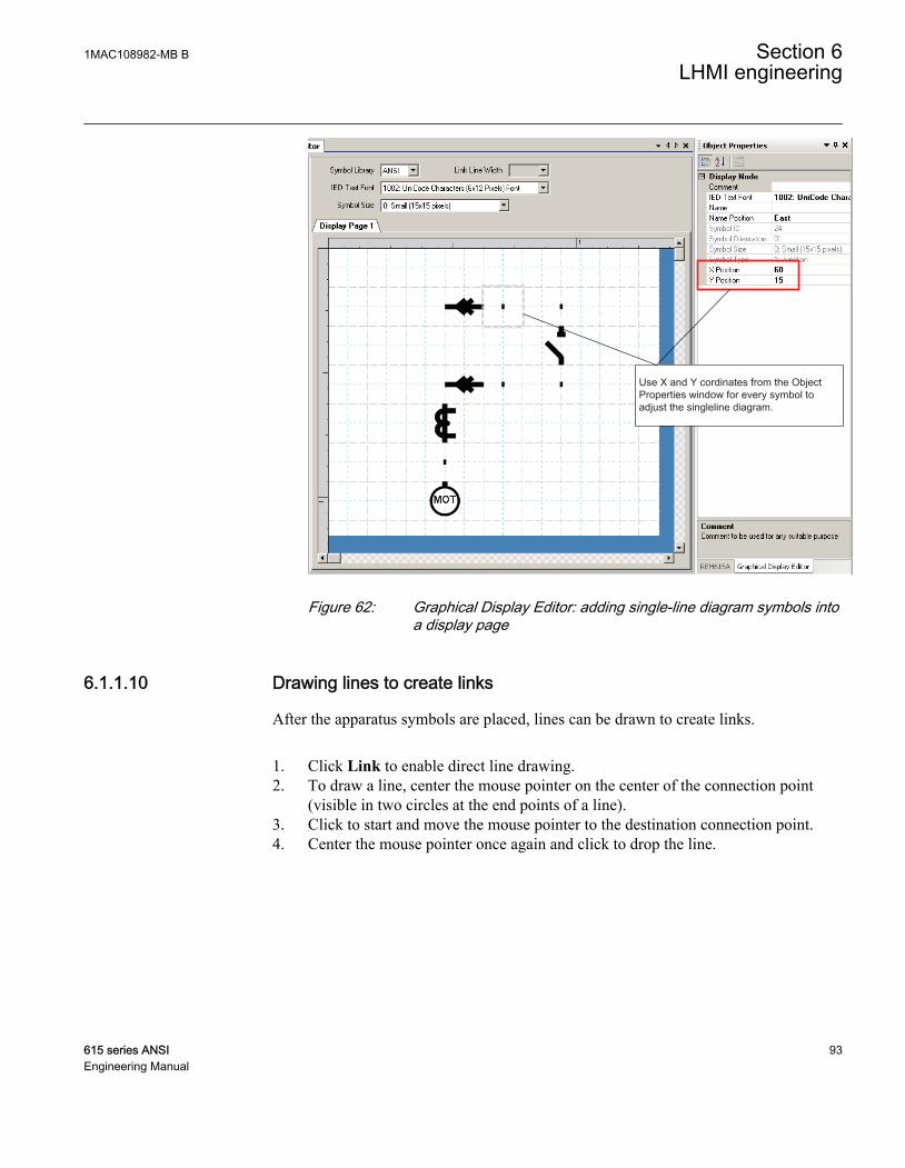
Use X and Y cordinates from the Object Properties window for every symbol to adjust the singleline diagram.
GUID-BB90E914-7B02-4D1E-A385-FB6D6305869C-ANSI V1 EN
Figure 62: Graphical Display Editor: adding single-line diagram symbols intoa display page
6.1.1.10 Drawing lines to create links
After the apparatus symbols are placed, lines can be drawn to create links.
1. Click Link to enable direct line drawing.2. To draw a line, center the mouse pointer on the center of the connection point
(visible in two circles at the end points of a line).3. Click to start and move the mouse pointer to the destination connection point.4. Center the mouse pointer once again and click to drop the line.
1MAC108982-MB B Section 6LHMI engineering
615 series ANSI 93Engineering Manual

Select Line draw icon from toolbar to draw lines between symbols
GUID-795A6797-D4D9-4705-A496-C3FBD771C211-ANSI V1 EN
Figure 63: Graphical Display Editor: drawing a line between symbols
5. Draw all line elements that are necessary.6. To finish the line drawing, click Select on the menu bar.
6.1.2 Bay configuration engineeringA view with a single-line diagram and measurements contains active living objects.The object values are updated by the IED periodically (measurement) or in case of anevent.
Once the symbols are placed on the HMI page, they must be linked to thecorresponding function block in the application configuration, which protects orcontrols the object that the symbol on the HMI page represents.
6.1.2.1 Creating a complete HMI display page
Section 6 1MAC108982-MB BLHMI engineering
94 615 series ANSIEngineering Manual

1. Make a sketch of how to present the single-line diagram.2. Place the apparatus, transformer and other symbols that are needed for the single-
line diagram into the raster boxes.3. Add Junction points where needed.4. Link the apparatus symbols with line elements.5. In the Object Properties view, adjust the text symbols while writing to north,
east, south or west.6. Place measurements when needed.7. Edit the name, unit and the number of the measurements' decimals.8. Select each object that has a dynamic link and make the link to the corresponding
process object.9. Check that you have selected the correct function block.
Function blocks of the same type can have different instance numbers.
GUID-F21E4F43-442D-4868-BAA3-EBA903E9C62E-ANSI V1 EN
Figure 64: Graphical Display Editor: establishing a dynamic object link
10. Ensure that all links are done.11. Save the complete picture.12. Write to the IED.13. Validate the single-line diagram on the IED.
1MAC108982-MB B Section 6LHMI engineering
615 series ANSI 95Engineering Manual

6.1.2.2 Linking process objects
To describe a process object within an IED, it needs to be established in the applicationconfiguration, configured when given the parameters by the Parameter Setting tool andlinked to be displayed in the HMI.
Three tools are involved in the described steps.
• Application Configuration tool for programming the application function block forthe apparatus and/or measurements
• Parameter Setting tool for adapting the settings and/or configuration parameters ofthe application function block
• Graphical Display Editor for establishing the link to update the selected dataattribute in the HMI of the application function block
The following application function blocks are used to deliver the needed information:
• Switch controller (of type CSWI) for an apparatus• All configured function blocks with measurements (of type MMXU) for the
measurements
1. Right-click the apparatus symbol and select Select Input Signal.A list of engineered switch control application function blocks opens.
2. Select the switch control application function block that corresponds to theselected apparatus.
3. Right-click the measurement symbol and select Select Input Signal.A list of the engineered measurement application function blocks opens.
4. Select the measurement application function block that corresponds to theselected symbol.
Section 6 1MAC108982-MB BLHMI engineering
96 615 series ANSIEngineering Manual

GUID-28A8463E-7A11-47FA-938F-17436CBFB0BD-ANSI V1 EN
Figure 65: Graphical Display Editor: input signal selection
The ordering number in the selection window of the process objects correspondsto the number given in the Parameter Setting tool tree and to the applicationfunction block in the Application Configuration tool.Only the apparatus and measurements that are configured in the applicationconfiguration program are displayed.
1MAC108982-MB B Section 6LHMI engineering
615 series ANSI 97Engineering Manual

GUID-1DB1A930-A312-4B55-8F68-3D8327A873FB V1 EN
Figure 66: Graphical Display Editor: object properties view for text insertion
Section 6 1MAC108982-MB BLHMI engineering
98 615 series ANSIEngineering Manual

Section 7 IEC 61850 communication engineering
7.1 IEC 61850 protocol references and pre-conditions
To engineer the IEC 61850 protocol interface for the IED, the following additionalmanuals or knowledge of their contents is required.
• Knowledge of the IEC 61850 engineering process as described in the IEC 61850standard
• The technical manual describes the function blocks defined as logical nodes• The IEC 61850 engineering guide• The IEC 61850 parameter list
7.2 IEC 61850 interface
For more information on the implementation of IEC 61850 in IEDs, seeIEC 61850 engineering guide.
1MAC108982-MB B Section 7IEC 61850 communication engineering
615 series ANSI 99Engineering Manual

7.2.1 IEC 61850 interface in the IED
IEC08000364.vsd
LNGOOSE
Send
Com
mun
icat
ion
hand
ler
IEC
618
50 p
roto
col
Commands
Eventhandler
Eventqueue
Com
man
d / I
N /
OU
T in
terfa
ce A
F pa
rt
GOOSE Send
GOOSE Receive
FBswith
monitoring and
commands
FBswith
monitoring only
GO
OS
E in
terf.
FBAFL
LNpart
FBAFL
LNpart
FBAFL
LNpart
LNGOOSE
Send
FBsGOOSEReceive
FBsGOOSEReceive
IEC08000364 V1 EN
Figure 67: IEC 61850: communication interface principle
IEC 61850 provides a method for identifying all signals that belong to a function.These signals are identified through the logical nodes representing the functions. Allsignal information for commands and monitoring are available in logical nodes.
Whenever a function block is instantiated in the Application Configuration tool,PCM600 automatically generates the corresponding logical node data.
7.2.1.1 GOOSE data exchange
The IEC 61850 protocol supports a method to directly exchange data between two ormore IEDs. This method is described in the IEC 61850–7–2 clause 15.
The concept is based on sending a multicast over the Ethernet. Whoever needs theinformation, detects the telegram by its source address, reads the telegram and handlesit. The telegrams are multicast sent and not acknowledged by the receiver.
Section 7 1MAC108982-MB BIEC 61850 communication engineering
100 615 series ANSIEngineering Manual

en05000830.vsd
IED 3
Sen
d
Data-set
Rec
eive
Rec
eive
LN
LN
LNLN
LN
IED 2
Sen
d
Data-set
Rec
eive
Rec
eive
LNLN
LN LN
IED 1
Sen
d
Data-set
Rec
eive
Rec
eive
LN
LNLN
LNLN
LN
IEC 61850 Subnetwork
IEC05000830 V1 EN
Figure 68: IEC 61850: horizontal communication principle, an example of threeIEDs where each IED communicate with all others
When a GOOSE message is to be sent, it is defined by configuring the data set with thedefined trigger option and GoCB. This engineering process is done in a stationconfiguration tool, for example, CCT600 or IET600. The task involves configuringlists with the signal, value and quality (data attributes) that belong to the GOOSEmessage data set.
In the opposite direction, the standard only defines the IED as a receiver of a GOOSEmessage. How the GOOSE input signals are handled must be defined in the IEDapplication configuration. The SCD file generated by CCT600 or IET600 (or any otherstation configuration tool) contains the GOOSE data sets as input data. The input datamust be connected to a GOOSE receive function blocks in the Signal Matrix tool.
7.2.2 Function view for IEC 61850 in PCM600The IED design is directly based on IEC 61850. Thus, the function blocks in PCM600tool use IEC 61850 logical node naming for function blocks. This relation isautomatically handled by the PCM600 tools.
The concept in the IED is such that the IEC 61850 data for each function instance isavailable in the data model, even when the function is not used in the application. Thismeans that it is not necessary to handle any instance information for the functionsregarding IEC 61850.
1MAC108982-MB B Section 7IEC 61850 communication engineering
615 series ANSI 101Engineering Manual

7.2.3 Station configuration description file typesThe IEC 61850 standard defines SCL file types in the sequence of engineering. Thesefiles have a different definition, which is explained in IEC 61850–6. Three of the filetypes are used in the engineering process for an IED.
• ICD = IED capability description• Capability description of the IED in logical nodes and their data. No
information about, for example, the communication configuration is included.• An IED is already extended by default data sets and report control blocks.
They are predefined by ABB. Changes or additional data sets, for example,have to be done with CCT600 or IET600.
• SCD = Station configuration description• A complete configuration description of all IEDs in a station and the full
engineering of process signals and communication structure is included. Thisincludes all the needed data sets and control blocks.
• CID = configured IED description• The CID file contains the information needed for configuring one specific
IED. The CID file contains the complete configuration description of onespecific IED. This includes the configured IED name, communication part,data sets and all control blocks.
7.3 IEC 61850 engineering process
The IEC 61850 standard defines how information is communicated in a substation. Theinformation communication can be divided into different parts.
• Description of the substation part, including the used logical nodes• Description of the IEDs with their logical nodes• Description of the communication network• Description of the engineering process
When exporting a SCL file from PCM600, the tool builds a default substation structureand creates default data sets and control blocks for vertical communication between thesubstation client and IEDs. For more information, see the IEC 61850 standards.
In the following example, it is assumed that PCM600 and CCT600 or IET600 are usedas the system configuration tools.
Section 7 1MAC108982-MB BIEC 61850 communication engineering
102 615 series ANSIEngineering Manual

1. SCL files are exported from PCM600. In this case, a SCD file. It is also possibleto export other SCL file types.
2. Horizontal and vertical communication is configured using the stationconfiguration tool, for example, CCT600 or IET600.
3. SCL files are imported to a PCM600 project. In this case, it is the updated SCD file.
IEC08000413.vsd
SCD file
do IED engineeringexport SCD file
PCM600 (1)
create projectimport SCD fileconfigure data setsconfigure Report CBsconfigure GOOSE CBsexport SCD file
CCT600 or IET600 (2)
import SCD filelink GOOSE input dataWrite to IED
PCM600 (3)
SCD file
IED 1 IED nIED 2 IED n-1
IEC08000413 V2 EN
Figure 69: IEC 61850: signal engineering procedure flow when a complete stationis exported as a SCD file
7.3.1 Exporting SCL files from PCM600A pre-condition for exporting SCL files from PCM600 is that all IEDs in the projectmust be engineered in PCM600. The IEDs require unique name and IP addresses andthey must be set according to the project definitions. IED configurations must befinalized as far as possible before starting the IEC 61850 configuration part.
7.3.1.1 Exporting SCD files
1. Select the station in the Plant Structure view.
1MAC108982-MB B Section 7IEC 61850 communication engineering
615 series ANSI 103Engineering Manual

IEC08000415-ANSI V1 EN
Figure 70: IEC 61850: selecting the station
2. Right-click the station and select Export.3. From the open standard Windows dialog box, select the location to store the file
and name it.4. Click Save.
The SCL Export Options dialog box opens.
IEC09000627-1-en.vsdIEC09000627 V1 EN
Figure 71: IEC 61850: selecting the SCL export option
5. Select the Export Private Sections.6. Click Export to export the private sections to the SCD file.
A progress window shows the ongoing export of the station.
Section 7 1MAC108982-MB BIEC 61850 communication engineering
104 615 series ANSIEngineering Manual

7.3.1.2 Exporting ICD or CID files
1. Select the IED in the Plant Structure view.2. Right-click the IED and select Export...
The Export dialog box opens.3. From the Save as type list, select the type of file to export.
• Configured IED description (.cid) for the IEC 61850 structure as needed forthe IED at runtime
• IED capability description (.icd) for the IEC 61850 structure
IEC08000416.vsdIEC08000416 V1 EN
Figure 72: IEC 61850: export IED file type selection
4. Click Save.The SCL Export Options dialog box opens.
5. Select the exportation method.• Export Private Sections• Export As SCL Template• Include Goose Sending IEDs
IEC08000418.vsdIEC08000418 V1 EN
Figure 73: IEC 61850: export IED file options
6. Click Export.
1MAC108982-MB B Section 7IEC 61850 communication engineering
615 series ANSI 105Engineering Manual

7.3.2 Engineering vertical and horizontal communicationFor IEC 61850 engineering a separate system configuration tool is needed to be usedwith PCM600. In PCM600 Ver. 2.3 or earlier the recommended tool is CCT600. InPCM600 Ver. 2.4 or later the recommended tool is IET600, which is also included inthe PCM600 Engineering Pro installation package.
1. Create a project in an IEC 61850 configuration tool.2. Import the SCD file created by PCM600.3. Conduct vertical communication engineering (monitoring direction).
3.1. Check the default data sets.3.2. Configure and/or reconfigure the default data sets.
Data sets meant for vertical reporting can only contain dataon the data object level, not on the data attribute level.
The data set for GOOSE may contain signals on dataattribute level.
3.3. Configure additional Report Control Blocks when needed for each data setused for vertical communication.
Up to five report clients can be configured.
3.4. Link the IED clients to the Report Control Blocks.4. Conduct horizontal communication engineering.
4.1. Configure GOOSE control blocks for each data set configured for GOOSEmessages.
One data must be included only once in the GOOSE data set.
4.2. Define the client IEDs for each GOOSE control block.4.3. Link the IEDs to the GOOSE control block that is to receive the GOOSE
control block.5. Export the updated SCD file.
Section 7 1MAC108982-MB BIEC 61850 communication engineering
106 615 series ANSIEngineering Manual

All data sets, Report Control Blocks and GOOSE control blocksmust be located in LLN0.
7.3.3 Importing SCL files to PCM600The IED engineering tool must be able to receive a SCD file or an ICD file as animport to receive the engineered communication extensions, for example, for thedifferent IEDs.
7.3.3.1 Importing SCD files
1. Select the station in the Plant Structure view.2. Right-click the station and select Import.3. From the open standard Windows menu, select the file to be imported and start
the reading.The SCL Import Options dialog box opens, quering how the file should behandled during the import.
IEC09000631-1-en.vsdIEC09000631 V1 EN
Figure 74: IEC 61850: importing a SCD file
4. In the SCL Import Options dialog box, select how to handle the file during theimport.
1MAC108982-MB B Section 7IEC 61850 communication engineering
615 series ANSI 107Engineering Manual

• Click Don't import IEDs of unknown type to protect the existing IEDs incase the SCD file does not match the original configuration in PCM600.
• Click Replace unknown if it is known that the file includes additionalIEDs that are needed. The IED of type “Generic IEC 61850 IED” is used tointegrate these kinds of IEDs into the plant structure, for example.
• Click Ignore PCM Object Type to update the IED object(s) in PCM600from the IED type(s) in the SCD file, whether or not the IED type(s) in theSCD file matches the IED object(s) in PCM600.
• Click Ignore Substation Section to not import the SSD file part of theSCD file.
5. Click Import when the file definition has been completed.A progress view displays the importing procedure.
6. Make connections from the sending IEDs to the receiving function blocks withthe Signal Matrix tool.Make connections between the signals that the server is sending and the functionblocks on the receiver's side.
7. Write the configuration to the IED.In the Plant Structure view, select the IED, right-click and select Write to IED.
Section 7 1MAC108982-MB BIEC 61850 communication engineering
108 615 series ANSIEngineering Manual

IEC09000616-ANSI V1 EN
Figure 75: Common write menu
The engineered data is written to the IED when executing acommon Write to IED operation.
1MAC108982-MB B Section 7IEC 61850 communication engineering
615 series ANSI 109Engineering Manual

7.3.3.2 Importing ICD or CID files
1. Select an existing IED to import IEC 61850 files.2. From the Files of type list, select the file type of IEC 61850 to be imported (ICD
or CID).The SCL Import Option dialog box opens.
3. In the SCL Import Option dialog box, select how the file is to be handled duringthe import.
IEC09000631-1-en.vsdIEC09000631 V1 EN
Figure 76: IEC 61850: SCL import options
• Don't import... protects the existing IEDs in case the SCD file does notmatch the original configuration in PCM600.
• Replace unknown... can be used when it is known that the file includesadditional IEDs that are needed. The IED of type “Generic IEC 61850 IED”is used to integrate these kinds of IEDs into, for example, the plant structure.
• Ignore PCM Object Type updates the IED object(s) in PCM600 from theIED type(s) in the SCD file, discarding whether or not the IED type(s) inthe SCD file matches the IED object(s) in PM600.
• Ignore Substation Section does not import the SSD file part of the SCD file.4. Click Import when the definition has been completed.
A progress view displays the importing procedure.
7.3.4 Writing communication configuration to the IEDIEC 61850 communication depends on the proper communication configuration in allIEDs that communicate via IEC 61850.
It is possible to make a configuration change in one IED, without affecting thecommunication engineering. For example, when the Application Configuration tool
Section 7 1MAC108982-MB BIEC 61850 communication engineering
110 615 series ANSIEngineering Manual

configuration is changed, but no changes are done to the instantiation or deletion offunctions that represent a logical node.
When a changed configuration is written to the IED, you are asked to update thecommunication configuration.
GUID-EEB7D9BD-5D8C-4A18-9A94-848B2821658D V1 EN
Figure 77: Updating the communication configuration in the IED with theconfiguration made in PCM600
1. Select whether or not to update the configuration.• Click Yes in the Update Communication window to update the
communication configuration part in the IED.• Click No in the Update Communication window to keep the
communication configuration part in the IED. Other parts of theconfiguration will be updated.
If no changes have been done in the communication configurationpart, click No in the Update Communication window.
1MAC108982-MB B Section 7IEC 61850 communication engineering
615 series ANSI 111Engineering Manual

112

Section 8 Glossary
615 series Series of numerical IEDs for low-end protection and supervisionapplications of utility substations, and industrial switchgear andequipment
ACT Application Configuration tool in PCM600; Trip statusANSI American National Standards InstituteCCT600 Communication Configuration tool in PCM600CID Configured IED descriptionCMT Communication Management tool in PCM600COMTRADE Common format for transient data exchange for power systems.
Defined by the IEEE Standard.DNP3 A distributed network protocol originally developed by
Westronic. The DNP3 Users Group has the ownership of theprotocol and assumes responsibility for its evolution.
EMC Electromagnetic compatibilityEthernet A standard for connecting a family of frame-based computer
networking technologies into a LANFTP File transfer protocolGDE Graphical Display Editor in PCM600GoCB GOOSE control blockGOOSE Generic Object-Oriented Substation EventHMI Human-machine interfaceHW HardwareI/O Input/outputICD IED capability descriptionIEC International Electrotechnical CommissionIEC 61850 International standard for substation communication and
modelingIED Intelligent electronic deviceIET600 Integrated Engineering Toolbox in PCM600
1MAC108982-MB B Section 8Glossary
615 series ANSI 113Engineering Manual

Instance Identical protection function blocks available in a standardconfiguration. By setting the application-specific parameters ofan instance, a protection function stage can be established.
IP address A set of four numbers between 0 and 255, separated by periods.Each server connected to the Internet is assigned a unique IPaddress that specifies the location for the TCP/IP protocol.
LAN Local area networkLED Light-emitting diodeLHMI Local human-machine interfaceModbus A serial communication protocol developed by the Modicon
company in 1979. Originally used for communication in PLCsand RTU devices.
NCC Network control centerPCM600 Protection and Control IED ManagerPST Parameter Setting tool in PCM600RJ-45 Galvanic connector typeSAB600 Substation automation builder toolSCD Substation configuration descriptionSCL Substation configuration languageSMT Signal Matrix tool in PCM600TCP Transmission Control ProtocolUDP User datagram protocolWAN Wide area networkWHMI Web human-machine interface
Section 8 1MAC108982-MB BGlossary
114 615 series ANSIEngineering Manual

115

Contact us
ABB Inc.Distribution Automation4300 Coral Ridge DriveCoral Springs, FL 33065, USAPhone +1 (800) 523-2620Phone +1 954-752-6700Fax +1 954 345-5329
www.abb.com/substationautomation
1MA
C10
8982
-MB
B©
Cop
yrig
ht 2
011
AB
B. A
ll rig
hts
rese
rved
.