Embed Size (px)
Citation preview
6.14 Transmission Line Safety and Nuisance
February 2007 6.14-1 Victorville 2 Hybrid Power Project
6.14 TRANSMISSION LINE SAFETY AND NUISANCE
This section discusses safety and nuisance issues associated with the transmission lines that will interconnect the VV2 Project with the regional grid. This section discusses the general aspects of the transmission lines and also addresses electric and magnetic fields for the various transmission line segments.
6.14.1 LORS Compliance
This section provides a list of applicable laws, ordinances, regulations, and standards (LORS) that apply to the proposed transmission line, substations and engineering.
6.14.1.1 Design and Construction
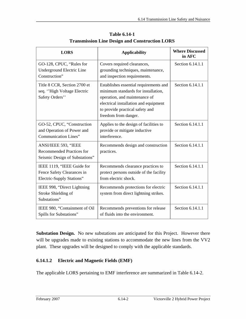
Table 6.14-1 lists the applicable LORS for the design and construction of the proposed transmission line.
Electrical Clearances. Typical high-voltage overhead transmission lines are composed of bare conductors connected to supporting structures by means of porcelain, glass, or plastic insulators. The air surrounding the energized conductor acts as the insulating medium. Maintaining sufficient clearances, or air space, around the conductors to protect the public and utility workers is paramount to the safe operation of the line. The safety clearance required around the conductors is determined by normal operating voltages, conductor temperatures, short-term abnormal voltages, windblown swinging conductors, contamination of the insulators, clearances for workers, and clearances for public safety. Minimum clearances are specified in the California Public Utility Commission (CPUC) General Order 95 (GO-95). Electric utilities, State regulators, and local ordinances may specify additional (more restrictive) clearances. Typically, clearances are specified for the following:
• Distance between the energized conductors themselves, • Distance between the energized conductors and the supporting structure, • Distance between the energized conductors and other power or communication wires
on the same supporting structure, or between other power or communication wires above or below the conductors,
• Distance from the energized conductors to the ground and features such as roadways, railroads, driveways, parking lots, navigable waterways, airports, etc.,
• Distance from the energized conductors to buildings and signs, and • Distance from the energized conductors to other parallel power lines.
6.14 Transmission Line Safety and Nuisance
February 2007 6.14-2 Victorville 2 Hybrid Power Project
Table 6.14-1 Transmission Line Design and Construction LORS
LORS Applicability Where Discussed in AFC
GO-128, CPUC, “Rules for Underground Electric Line Construction”
Covers required clearances, grounding techniques, maintenance, and inspection requirements.
Section 6.14.1.1
Title 8 CCR, Section 2700 et seq. ‘’High Voltage Electric Safety Orders’’
Establishes essential requirements and minimum standards for installation, operation, and maintenance of electrical installation and equipment to provide practical safety and freedom from danger.
Section 6.14.1.1
GO-52, CPUC, “Construction and Operation of Power and Communication Lines”
Applies to the design of facilities to provide or mitigate inductive interference.
Section 6.14.1.1
ANSI/IEEE 593, “IEEE Recommended Practices for Seismic Design of Substations”
Recommends design and construction practices.
Section 6.14.1.1
IEEE 1119, “IEEE Guide for Fence Safety Clearances in Electric-Supply Stations”
Recommends clearance practices to protect persons outside of the facility from electric shock.
Section 6.14.1.1
IEEE 998, “Direct Lightning Stroke Shielding of Substations”
Recommends protections for electric system from direct lightning strikes.
Section 6.14.1.1
IEEE 980, “Containment of Oil Spills for Substations”
Recommends preventions for release of fluids into the environment.
Section 6.14.1.1
Substation Design. No new substations are anticipated for this Project. However there will be upgrades made to existing stations to accommodate the new lines from the VV2 plant. These upgrades will be designed to comply with the applicable standards.
6.14.1.2 Electric and Magnetic Fields (EMF)
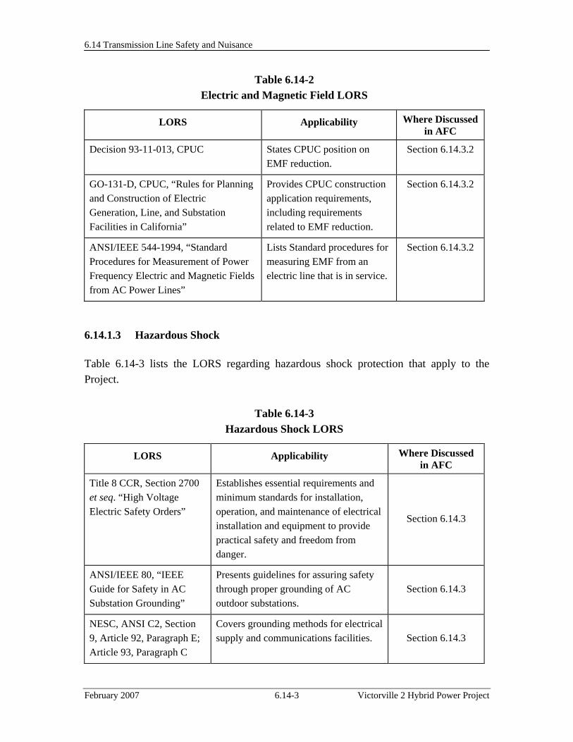
The applicable LORS pertaining to EMF interference are summarized in Table 6.14-2.
6.14 Transmission Line Safety and Nuisance
February 2007 6.14-3 Victorville 2 Hybrid Power Project
Table 6.14-2 Electric and Magnetic Field LORS
LORS Applicability Where Discussed in AFC
Decision 93-11-013, CPUC States CPUC position on EMF reduction.
Section 6.14.3.2
GO-131-D, CPUC, “Rules for Planning and Construction of Electric Generation, Line, and Substation Facilities in California”
Provides CPUC construction application requirements, including requirements related to EMF reduction.
Section 6.14.3.2
ANSI/IEEE 544-1994, “Standard Procedures for Measurement of Power Frequency Electric and Magnetic Fields from AC Power Lines”
Lists Standard procedures for measuring EMF from an electric line that is in service.
Section 6.14.3.2
6.14.1.3 Hazardous Shock
Table 6.14-3 lists the LORS regarding hazardous shock protection that apply to the Project.
Table 6.14-3 Hazardous Shock LORS
LORS Applicability Where Discussed in AFC
Title 8 CCR, Section 2700 et seq. “High Voltage Electric Safety Orders”
Establishes essential requirements and minimum standards for installation, operation, and maintenance of electrical installation and equipment to provide practical safety and freedom from danger.
Section 6.14.3
ANSI/IEEE 80, “IEEE Guide for Safety in AC Substation Grounding”
Presents guidelines for assuring safety through proper grounding of AC outdoor substations.
Section 6.14.3
NESC, ANSI C2, Section 9, Article 92, Paragraph E; Article 93, Paragraph C
Covers grounding methods for electrical supply and communications facilities. Section 6.14.3
6.14 Transmission Line Safety and Nuisance
February 2007 6.14-4 Victorville 2 Hybrid Power Project
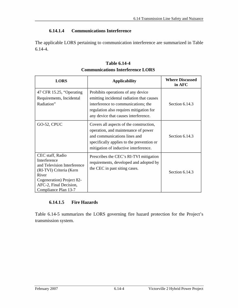
6.14.1.4 Communications Interference
The applicable LORS pertaining to communication interference are summarized in Table 6.14-4.
Table 6.14-4 Communications Interference LORS
LORS Applicability Where Discussed in AFC
47 CFR 15.25, “Operating Requirements, Incidental Radiation”
Prohibits operations of any device emitting incidental radiation that causes interference to communications; the regulation also requires mitigation for any device that causes interference.
Section 6.14.3
GO-52, CPUC Covers all aspects of the construction, operation, and maintenance of power and communications lines and specifically applies to the prevention or mitigation of inductive interference.
Section 6.14.3
CEC staff, Radio Interference and Television Interference (RI-TVI) Criteria (Kern River Cogeneration) Project 82- AFC-2, Final Decision, Compliance Plan 13-7
Prescribes the CEC’s RI-TVI mitigation requirements, developed and adopted by the CEC in past siting cases.
Section 6.14.3
6.14.1.5 Fire Hazards
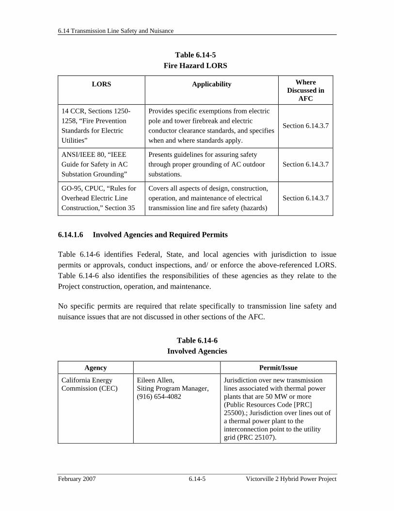
Table 6.14-5 summarizes the LORS governing fire hazard protection for the Project’s transmission system.
6.14 Transmission Line Safety and Nuisance
February 2007 6.14-5 Victorville 2 Hybrid Power Project
Table 6.14-5 Fire Hazard LORS
LORS Applicability Where Discussed in
AFC
14 CCR, Sections 1250-1258, “Fire Prevention Standards for Electric Utilities”
Provides specific exemptions from electric pole and tower firebreak and electric conductor clearance standards, and specifies when and where standards apply.
Section 6.14.3.7
ANSI/IEEE 80, “IEEE Guide for Safety in AC Substation Grounding”
Presents guidelines for assuring safety through proper grounding of AC outdoor substations.
Section 6.14.3.7
GO-95, CPUC, “Rules for Overhead Electric Line Construction,” Section 35
Covers all aspects of design, construction, operation, and maintenance of electrical transmission line and fire safety (hazards)
Section 6.14.3.7
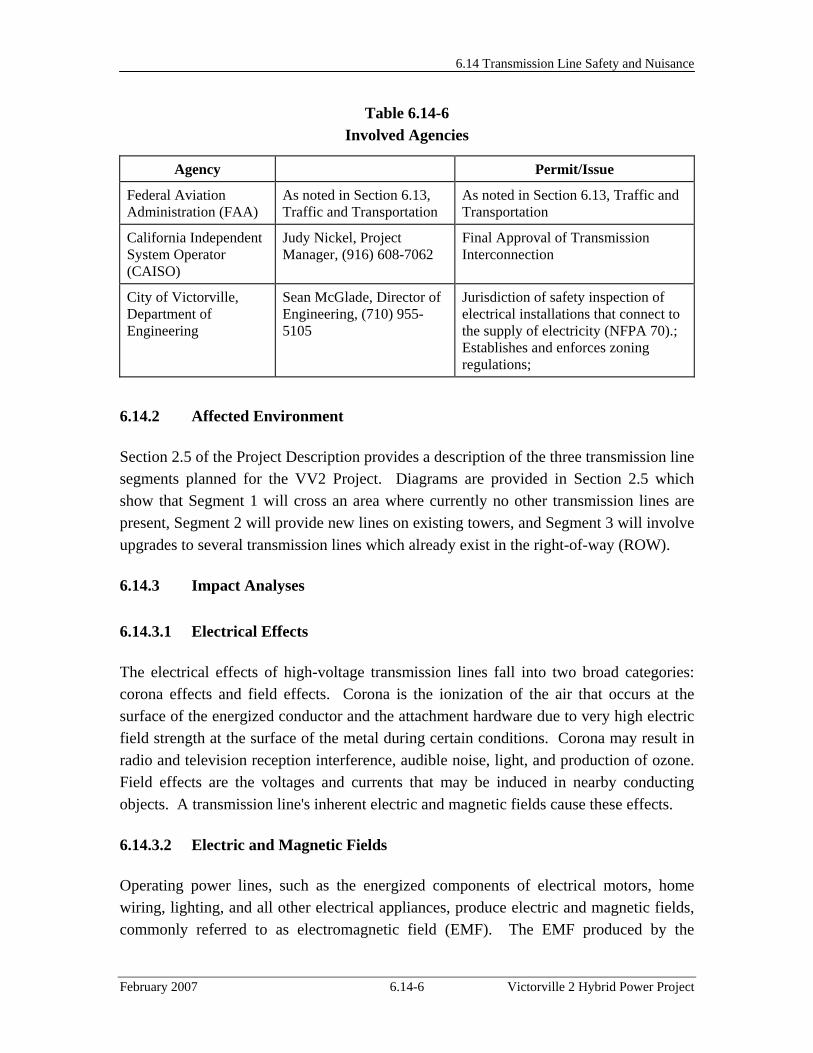
6.14.1.6 Involved Agencies and Required Permits
Table 6.14-6 identifies Federal, State, and local agencies with jurisdiction to issue permits or approvals, conduct inspections, and/ or enforce the above-referenced LORS. Table 6.14-6 also identifies the responsibilities of these agencies as they relate to the Project construction, operation, and maintenance.
No specific permits are required that relate specifically to transmission line safety and nuisance issues that are not discussed in other sections of the AFC.
Table 6.14-6 Involved Agencies
Agency Permit/Issue
California Energy Commission (CEC)
Eileen Allen, Siting Program Manager, (916) 654-4082
Jurisdiction over new transmission lines associated with thermal power plants that are 50 MW or more (Public Resources Code [PRC] 25500).; Jurisdiction over lines out of a thermal power plant to the interconnection point to the utility grid (PRC 25107).
6.14 Transmission Line Safety and Nuisance
February 2007 6.14-6 Victorville 2 Hybrid Power Project
Table 6.14-6 Involved Agencies
Agency Permit/Issue
Federal Aviation Administration (FAA)
As noted in Section 6.13, Traffic and Transportation
As noted in Section 6.13, Traffic and Transportation
California Independent System Operator (CAISO)
Judy Nickel, Project Manager, (916) 608-7062
Final Approval of Transmission Interconnection
City of Victorville, Department of Engineering
Sean McGlade, Director of Engineering, (710) 955-5105
Jurisdiction of safety inspection of electrical installations that connect to the supply of electricity (NFPA 70).; Establishes and enforces zoning regulations;
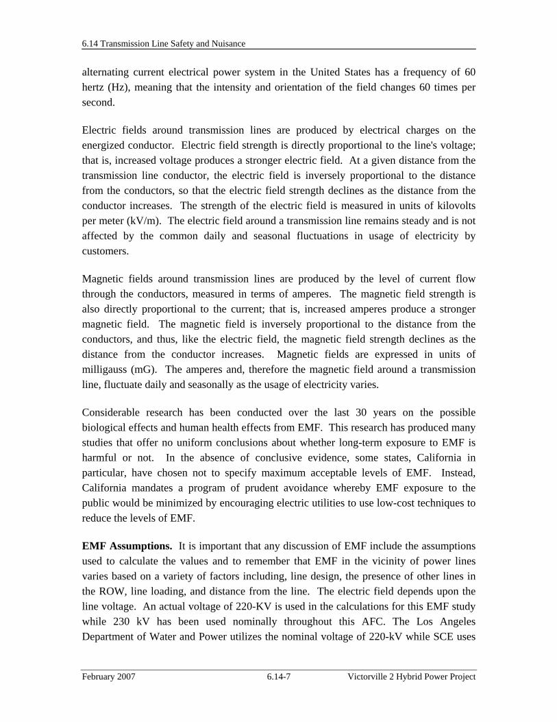
6.14.2 Affected Environment
Section 2.5 of the Project Description provides a description of the three transmission line segments planned for the VV2 Project. Diagrams are provided in Section 2.5 which show that Segment 1 will cross an area where currently no other transmission lines are present, Segment 2 will provide new lines on existing towers, and Segment 3 will involve upgrades to several transmission lines which already exist in the right-of-way (ROW).
6.14.3 Impact Analyses
6.14.3.1 Electrical Effects
The electrical effects of high-voltage transmission lines fall into two broad categories: corona effects and field effects. Corona is the ionization of the air that occurs at the surface of the energized conductor and the attachment hardware due to very high electric field strength at the surface of the metal during certain conditions. Corona may result in radio and television reception interference, audible noise, light, and production of ozone. Field effects are the voltages and currents that may be induced in nearby conducting objects. A transmission line's inherent electric and magnetic fields cause these effects.
6.14.3.2 Electric and Magnetic Fields
Operating power lines, such as the energized components of electrical motors, home wiring, lighting, and all other electrical appliances, produce electric and magnetic fields, commonly referred to as electromagnetic field (EMF). The EMF produced by the
6.14 Transmission Line Safety and Nuisance
February 2007 6.14-7 Victorville 2 Hybrid Power Project
alternating current electrical power system in the United States has a frequency of 60 hertz (Hz), meaning that the intensity and orientation of the field changes 60 times per second.
Electric fields around transmission lines are produced by electrical charges on the energized conductor. Electric field strength is directly proportional to the line's voltage; that is, increased voltage produces a stronger electric field. At a given distance from the transmission line conductor, the electric field is inversely proportional to the distance from the conductors, so that the electric field strength declines as the distance from the conductor increases. The strength of the electric field is measured in units of kilovolts per meter (kV/m). The electric field around a transmission line remains steady and is not affected by the common daily and seasonal fluctuations in usage of electricity by customers.
Magnetic fields around transmission lines are produced by the level of current flow through the conductors, measured in terms of amperes. The magnetic field strength is also directly proportional to the current; that is, increased amperes produce a stronger magnetic field. The magnetic field is inversely proportional to the distance from the conductors, and thus, like the electric field, the magnetic field strength declines as the distance from the conductor increases. Magnetic fields are expressed in units of milligauss (mG). The amperes and, therefore the magnetic field around a transmission line, fluctuate daily and seasonally as the usage of electricity varies.
Considerable research has been conducted over the last 30 years on the possible biological effects and human health effects from EMF. This research has produced many studies that offer no uniform conclusions about whether long-term exposure to EMF is harmful or not. In the absence of conclusive evidence, some states, California in particular, have chosen not to specify maximum acceptable levels of EMF. Instead, California mandates a program of prudent avoidance whereby EMF exposure to the public would be minimized by encouraging electric utilities to use low-cost techniques to reduce the levels of EMF.
EMF Assumptions. It is important that any discussion of EMF include the assumptions used to calculate the values and to remember that EMF in the vicinity of power lines varies based on a variety of factors including, line design, the presence of other lines in the ROW, line loading, and distance from the line. The electric field depends upon the line voltage. An actual voltage of 220-KV is used in the calculations for this EMF study while 230 kV has been used nominally throughout this AFC. The Los Angeles Department of Water and Power utilizes the nominal voltage of 220-kV while SCE uses
6.14 Transmission Line Safety and Nuisance
February 2007 6.14-8 Victorville 2 Hybrid Power Project
230-kV. The use of either voltage in this document is consistent with the industry use of the 230-kV term to describe the nominal voltage for this class of system.
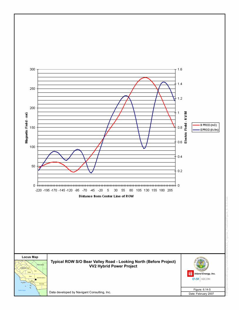
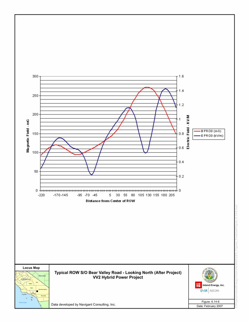
The magnetic field is proportional to the line loading (amperes), which varies based on the interconnected power system loading, and the power output of the generating facility as output changes to meet increases or decreases in demand for electric power. The line loading values were based on the maximum load carrying capability of each line section, which will produce a worst case value for the magnetic field.
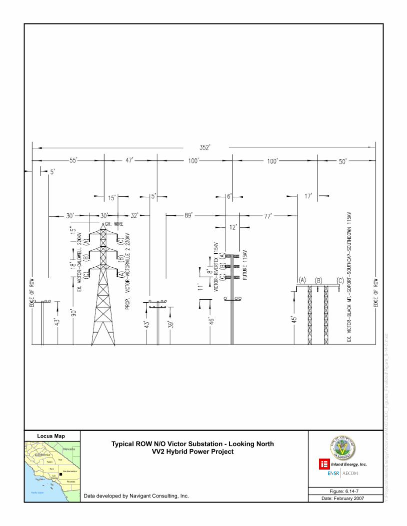
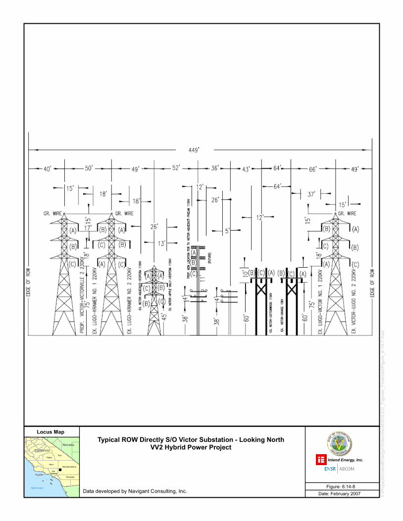
The arrangement of the transmission lines in the ROW is another important consideration for the field calculation. The phase arrangement of each line has been entered into the model used for the field calculation. As such, there will be some field calculation where adjacent lines on double-circuit towers are configured with phases A, B, and C arranged from top to bottom, while the other circuit is configured with phases C, B, and A from top to bottom.
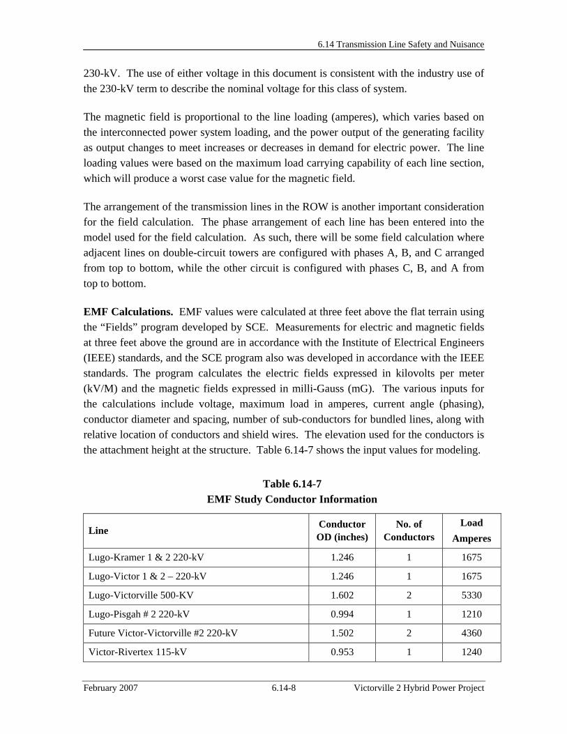
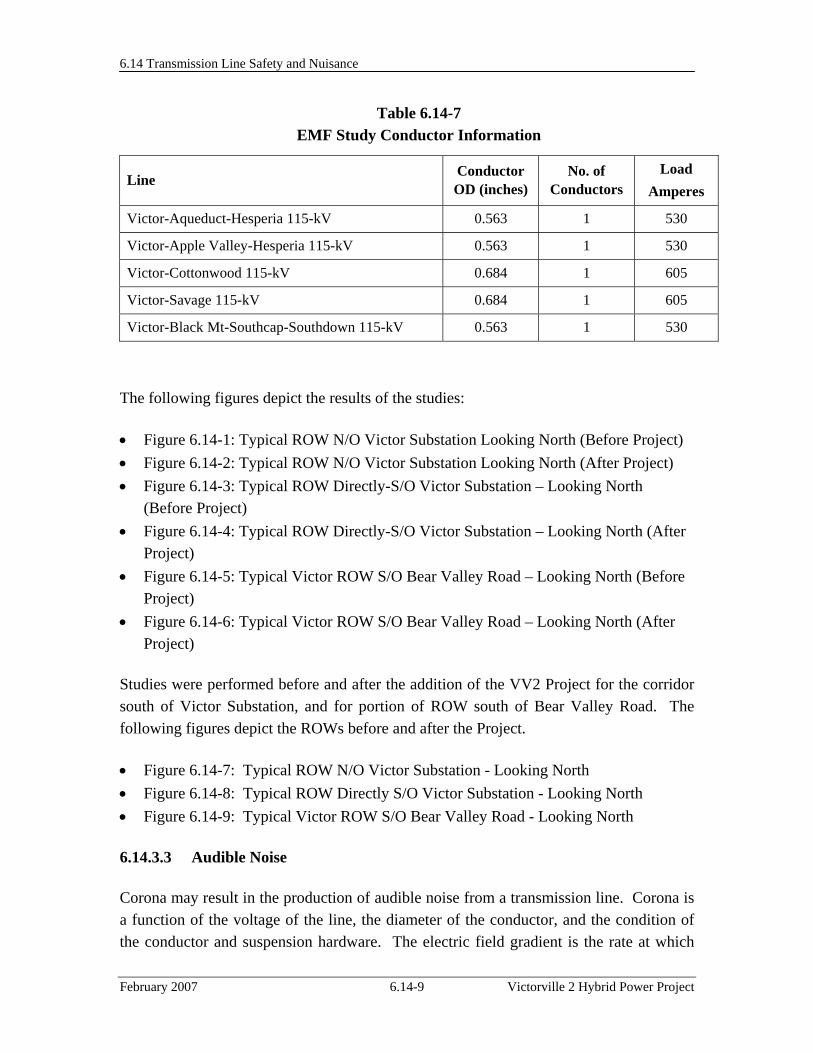
EMF Calculations. EMF values were calculated at three feet above the flat terrain using the “Fields” program developed by SCE. Measurements for electric and magnetic fields at three feet above the ground are in accordance with the Institute of Electrical Engineers (IEEE) standards, and the SCE program also was developed in accordance with the IEEE standards. The program calculates the electric fields expressed in kilovolts per meter (kV/M) and the magnetic fields expressed in milli-Gauss (mG). The various inputs for the calculations include voltage, maximum load in amperes, current angle (phasing), conductor diameter and spacing, number of sub-conductors for bundled lines, along with relative location of conductors and shield wires. The elevation used for the conductors is the attachment height at the structure. Table 6.14-7 shows the input values for modeling.
Table 6.14-7 EMF Study Conductor Information
Line Conductor OD (inches)
No. of Conductors
Load Amperes
Lugo-Kramer 1 & 2 220-kV 1.246 1 1675
Lugo-Victor 1 & 2 – 220-kV 1.246 1 1675
Lugo-Victorville 500-KV 1.602 2 5330
Lugo-Pisgah # 2 220-kV 0.994 1 1210
Future Victor-Victorville #2 220-kV 1.502 2 4360
Victor-Rivertex 115-kV 0.953 1 1240
6.14 Transmission Line Safety and Nuisance
February 2007 6.14-9 Victorville 2 Hybrid Power Project
Table 6.14-7 EMF Study Conductor Information
Line Conductor OD (inches)
No. of Conductors
Load Amperes
Victor-Aqueduct-Hesperia 115-kV 0.563 1 530
Victor-Apple Valley-Hesperia 115-kV 0.563 1 530
Victor-Cottonwood 115-kV 0.684 1 605
Victor-Savage 115-kV 0.684 1 605
Victor-Black Mt-Southcap-Southdown 115-kV 0.563 1 530
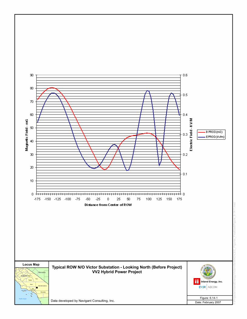
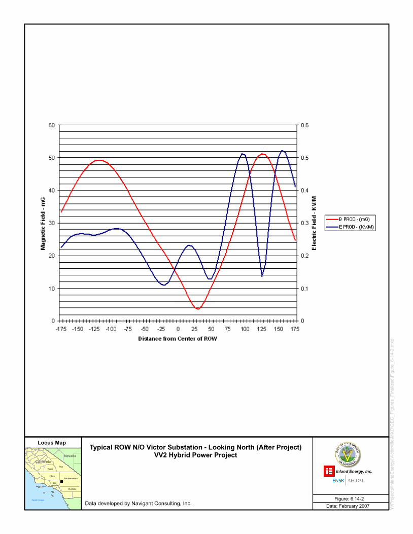
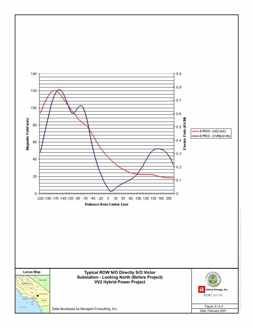
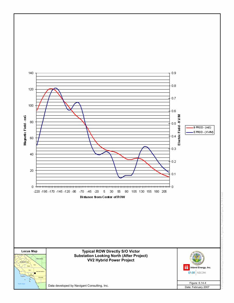
The following figures depict the results of the studies:
• Figure 6.14-1: Typical ROW N/O Victor Substation Looking North (Before Project) • Figure 6.14-2: Typical ROW N/O Victor Substation Looking North (After Project) • Figure 6.14-3: Typical ROW Directly-S/O Victor Substation – Looking North
(Before Project) • Figure 6.14-4: Typical ROW Directly-S/O Victor Substation – Looking North (After
Project) • Figure 6.14-5: Typical Victor ROW S/O Bear Valley Road – Looking North (Before
Project) • Figure 6.14-6: Typical Victor ROW S/O Bear Valley Road – Looking North (After
Project)
Studies were performed before and after the addition of the VV2 Project for the corridor south of Victor Substation, and for portion of ROW south of Bear Valley Road. The following figures depict the ROWs before and after the Project.
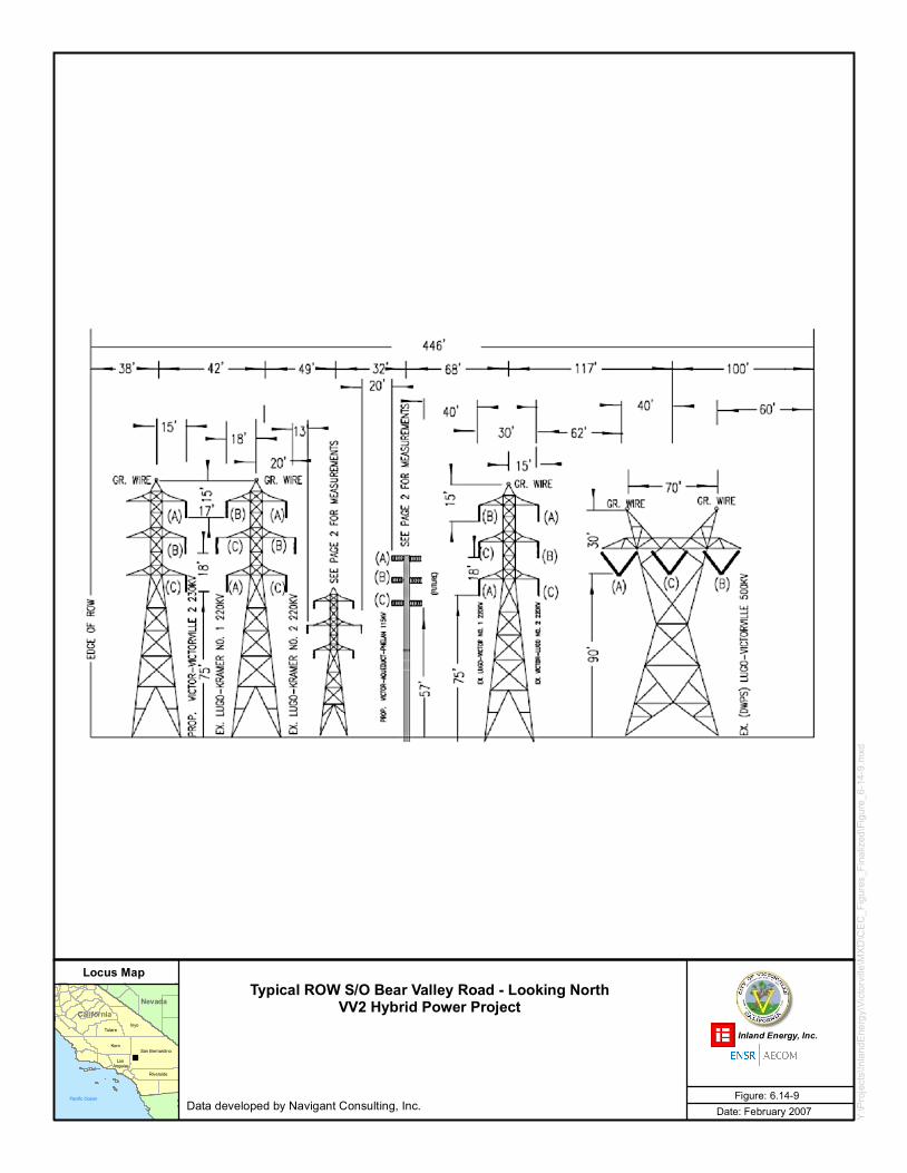
• Figure 6.14-7: Typical ROW N/O Victor Substation - Looking North • Figure 6.14-8: Typical ROW Directly S/O Victor Substation - Looking North • Figure 6.14-9: Typical Victor ROW S/O Bear Valley Road - Looking North
6.14.3.3 Audible Noise
Corona may result in the production of audible noise from a transmission line. Corona is a function of the voltage of the line, the diameter of the conductor, and the condition of the conductor and suspension hardware. The electric field gradient is the rate at which
6.14 Transmission Line Safety and Nuisance
February 2007 6.14-10 Victorville 2 Hybrid Power Project
the electric field changes and is directly related to the line voltage.
The electric field gradient is greatest at the surface of the conductor. Large-diameter conductors have lower electric field gradients at the conductor surface and, hence, lower corona than smaller conductors, everything else being equal. Also, irregularities (such as nicks and scrapes on the conductor surface) or sharp edges on suspension hardware concentrate the electric field at these locations and, thus, increase corona at these spots. Similarly, contamination on the conductor surface, such as dust or insects, can cause irregularities that are a source for corona. Raindrops, snow, fog, and condensation are also sources of irregularities. Corona typically becomes a design concern for transmission lines having voltages of 345-kV and above. Since the Project will be connected at 230-kV, it is expected that no corona-related design issues will be encountered.
The construction and operation of the VV2 Project, including its interconnection with SCE's transmission system, is not expected to result in significant increases in EMF levels or audible noise.
6.14.3.4 Induced Current and Voltages
A conducting object, such as a vehicle or person in an electric field, will experience induced voltages and currents. The strength of the induced current will depend on the electric field strength, the size and shape of the conducting object, and the object-to-ground resistance. When a conducting object is isolated from the ground and a grounded person touches the object, a perceptible current or shock may occur as the current flows to ground. Proper design standards will be implemented to prevent hazardous and nuisance shocks by ensuring that metallic objects on or near the right-of-way are grounded and that sufficient clearances are provided at roadways and parking lots to keep electric fields at these locations low enough to prevent vehicle short-circuit currents from exceeding 5 milliamperes (mA).
Magnetic fields can also induce voltages and currents in conducting objects. Typically, this requires a long metallic object, such as a wire fence or above-ground pipeline that is grounded at only one location. A person who closes an electrical loop by grounding the object at a different location will experience a shock similar to that described above for an ungrounded object. Design standards for managing this issue dictate multiple grounds on fences or pipelines, especially those that are oriented parallel to the transmission line.
The VV2 Project 230-kV transmission interconnection will be constructed in conformance with CPUC GO-95 and Title 8 CCR 2700 requirements. These regulations
6.14 Transmission Line Safety and Nuisance
February 2007 6.14-11 Victorville 2 Hybrid Power Project
require sufficient grounding to ensure that hazardous shocks do not occur. Therefore, hazardous shocks are unlikely as a result of Project construction, operation, or maintenance. A shield wire will be installed as a feature of the Project.
6.14.3.5 Communications Interference
Corona caused by the power line can cause interference with radio and television reception. The line will be designed to minimize corona noise by proper selection of the conductor and associated hardware. Pre-construction surveys of ambient noise levels will be performed, and then compared to the noise levels after construction. Interference complaints from the public will be investigated, and repairs made as needed to resolve the interference complaint.
6.14.3.6 Aviation Safety
As discussed in Section 6.13.3.3, Traffic and Transportation, FAA regulations, Part 77, establish standards for determining obstructions in navigable airspace and sets forth requirements for notification of proposed construction. Section 6.13 finds that the Project is in conformance with FAA requirements and that visible plumes from the HRSGs and cooling tower and potential turbulence from the HRSG stack plumes are not expected to pose hazards for aircraft operations at SCLA.
The HDPP is located immediately adjacent to SCLA whereas the VV2 Project is located further to the northwest with its transmission facilities further west. Appendix L is a letter from SCLA’s Airport Operations Supervisor citing that the HDPP has not posed “any hazard to aircraft operations.” As EMF issues that affected aircraft communications or avionics likely would be considered a hazard to aircraft operations, it is reasonable to assume that such issues have not arisen for HDPP. As EMF issues for the VV2 Project would be similar to those associated with HDPP because of the similarities between the two projects, it is expected that VV2 Project transmission line impacts on aviation safety would be less than significant. The design of the VV2 Project transmission system will incorporate the needed measures to ensure aviation safety.
6.14.3.7 Fire Hazards
The proposed 230-kV transmission interconnection lines will be designed, constructed, and maintained in accordance with the CPUC’s GO-95, which establishes clearances from other man-made and natural structures as well as tree-trimming requirements to reduce/avoid fire hazards. SCE will maintain the transmission line corridor and immediate area in accordance with existing regulations and accepted industry practices
6.14 Transmission Line Safety and Nuisance
February 2007 6.14-12 Victorville 2 Hybrid Power Project
that will include identification and abatement of any fire hazards.
6.14.4 Mitigation Measures
No significant transmission line-related impacts were identified as a result of the VV2 Project studies.
The VV2 Project will be designed, constructed, operated, and maintained in accordance with the applicable LORS and to minimize EMF at the edges of the right-of-way. Impacts will be less than significant with Project implementation as described in this section (e.g., insulators and hardware selected to minimize corona noise; pre- and post-Project noise surveys performed to document ambient condition change caused by the line, and procedures to investigate and resolve interference complaints). No additional mitigation is required. However, should additional currently unforeseen issues arise, they will be addressed to ensure that impacts remain less than significant.
6.14.5 References
CEC staff. Radio Interference and Television Interference (RI-TVI) Criteria (Kern River Cogeneration) Project 82-AFC-2, Final Decision, Compliance Plan 13-7.
CaliforniaNevada
Kern
Inyo
San Bernardino
Tulare
Riverside
Los Angeles
Pacific Ocean
Y:\Pr
ojects
\Inlan
dEne
rgy\Vi
ctorvi
lle\M
XD\C
EC_F
igures
_Fina
lized
\Figu
re_6-1
4-1.m
xd
Locus Map
Date: February 2007Figure: 6.14-1
Inland Energy, Inc.
Typical ROW N/O Victor Substation - Looking North (Before Project)VV2 Hybrid Power Project
Data developed by Navigant Consulting, Inc.
CaliforniaNevada
Kern
Inyo
San Bernardino
Tulare
Riverside
Los Angeles
Pacific Ocean
Y:\Pr
ojects
\Inlan
dEne
rgy\Vi
ctorvi
lle\M
XD\C
EC_F
igures
_Fina
lized
\Figu
re_6-1
4-2.m
xd
Locus Map
Date: February 2007Figure: 6.14-2
Inland Energy, Inc.
Typical ROW N/O Victor Substation - Looking North (After Project)VV2 Hybrid Power Project
Data developed by Navigant Consulting, Inc.
CaliforniaNevada
Kern
Inyo
San Bernardino
Tulare
Riverside
Los Angeles
Pacific Ocean
Y:\Pr
ojects
\Inlan
dEne
rgy\Vi
ctorvi
lle\M
XD\C
EC_F
igures
_Fina
lized
\Figu
re_6-1
4-3.m
xd
Locus Map
Date: February 2007Figure: 6.14-3
Inland Energy, Inc.
Typical ROW N/O Directly S/O VictorSubstation - Looking North (Before Project)
VV2 Hybrid Power Project
Data developed by Navigant Consulting, Inc.
CaliforniaNevada
Kern
Inyo
San Bernardino
Tulare
Riverside
Los Angeles
Pacific Ocean
Y:\Pr
ojects
\Inlan
dEne
rgy\Vi
ctorvi
lle\M
XD\C
EC_F
igures
_Fina
lized
\Figu
re_6-1
4-2.m
xd
Locus Map
Date: February 2007Figure: 6.14-4
Inland Energy, Inc.
Typical ROW Directly S/O VictorSubstation Looking North (After Project)
VV2 Hybrid Power Project
Data developed by Navigant Consulting, Inc.
CaliforniaNevada
Kern
Inyo
San Bernardino
Tulare
Riverside
Los Angeles
Pacific Ocean
Y:\Pr
ojects
\Inlan
dEne
rgy\Vi
ctorvi
lle\M
XD\C
EC_F
igures
_Fina
lized
\Figu
re_6-1
4-5.m
xd
Locus Map
Date: February 2007Figure: 6.14-5
Inland Energy, Inc.
Typical ROW S/O Bear Valley Road - Looking North (Before Project)VV2 Hybrid Power Project
Data developed by Navigant Consulting, Inc.
CaliforniaNevada
Kern
Inyo
San Bernardino
Tulare
Riverside
Los Angeles
Pacific Ocean
Y:\Pr
ojects
\Inlan
dEne
rgy\Vi
ctorvi
lle\M
XD\C
EC_F
igures
_Fina
lized
\Figu
re_6-1
4-6.m
xd
Locus Map
Date: February 2007Figure: 6.14-6
Inland Energy, Inc.
Typical ROW S/O Bear Valley Road - Looking North (After Project)VV2 Hybrid Power Project
Data developed by Navigant Consulting, Inc.
CaliforniaNevada
Kern
Inyo
San Bernardino
Tulare
Riverside
Los Angeles
Pacific Ocean
Y:\Pr
ojects
\Inlan
dEne
rgy\Vi
ctorvi
lle\M
XD\C
EC_F
igures
_Fina
lized
\Figu
re_6-1
4-5.m
xd
Locus Map
Date: February 2007Figure: 6.14-7
Inland Energy, Inc.
Typical ROW N/O Victor Substation - Looking NorthVV2 Hybrid Power Project
Data developed by Navigant Consulting, Inc.
CaliforniaNevada
Kern
Inyo
San Bernardino
Tulare
Riverside
Los Angeles
Pacific Ocean
Y:\Pr
ojects
\Inlan
dEne
rgy\Vi
ctorvi
lle\M
XD\C
EC_F
igures
_Fina
lized
\Figu
re_6-1
4-7.m
xd
Locus Map
Date: February 2007Figure: 6.14-8
Inland Energy, Inc.
Typical ROW Directly S/O Victor Substation - Looking NorthVV2 Hybrid Power Project
Data developed by Navigant Consulting, Inc.
CaliforniaNevada
Kern
Inyo
San Bernardino
Tulare
Riverside
Los Angeles
Pacific Ocean
Y:\Pr
ojects
\Inlan
dEne
rgy\Vi
ctorvi
lle\M
XD\C
EC_F
igures
_Fina
lized
\Figu
re_6-1
4-9.m
xd
Locus Map
Date: February 2007Figure: 6.14-9
Inland Energy, Inc.
Typical ROW S/O Bear Valley Road - Looking NorthVV2 Hybrid Power Project
Data developed by Navigant Consulting, Inc.