Embed Size (px)
Citation preview

POWERTECH™13.5 L OEM
6135HF485/HF475 Emissions Diesel Engines
OPERATOR’S MANUAL13.5 L OEM 6135HF485/HF475Emissions Diesel Engines
OMRG36873 ISSUE 16DEC10 (ENGLISH)
CALIFORNIAProposition 65 Warning
Diesel engine exhaust and some of its constituentsare known to the State of California to cause cancer,
birth defects, and other reproductive harm.
If this product contains a gasoline engine:
WARNING
The engine exhaust from this product containschemicals known to the State of California to causecancer, birth defects or other reproductive harm.
The State of California requires the above two warnings.
Additional Proposition 65 Warnings can be found in this manual.
John Deere Power SystemsLITHO IN U.S.A.
Introduction
JR74534,00002EA 1916DEC101/1
Foreword
READ THIS MANUAL carefully to learn how to operateand service your engine correctly. Failure to do so couldresult in personal injury or equipment damage.
THIS MANUAL SHOULD BE CONSIDERED a permanentpart of your engine and should remain with the enginewhen you sell it.
MEASUREMENTS IN THIS MANUAL are given in bothmetric and customary U.S. unit equivalents. Use onlycorrect replacement parts and fasteners. Metric and inchfasteners may require a specific metric or inch wrench.
RIGHTHAND AND LEFTHAND sides are determined bystanding at the drive or flywheel end (rear) of the engineand facing toward the front of the engine.
WRITE ENGINE SERIAL NUMBERS and option codesin the spaces indicated in the Record Keeping section.Accurately record all the numbers. Your dealer alsoneeds these numbers when you order parts. File theidentification numbers in a secure place off the engine.
SETTING FUEL DELIVERY beyond published factoryspecifications or otherwise overpowering will result in lossof warranty protection for this engine.
CERTAIN ENGINE ACCESSORIES such as radiator,air cleaner, and instruments are optional equipment onJohn Deere OEM Engines. These accessories may beprovided by the equipment manufacturer instead of JohnDeere. This operator’s manual applies only to the engineand those options available through the John Deeredistribution network.
NOTE: This operator’s manual covers only enginesprovided to OEM (Original EquipmentManufacturers). For engines in Deere machines,refer to the machine operator’s manual.
This manual covers primarily the PowerTech Plus 13.5L (6135HF485) OEM engines. These engines meetemission standards for EPA Tier 3 and EU Stage III A.
010311
PN=2

Introduction
OURGP11,0000251 1918SEP071/1
Engine Owner
John Deere Engine Owner:
Don’t wait until you need warranty or other serviceto meet your local John Deere Engine Distributoror Service Dealer. To register your engine forwarranty via the Internet, use the following URL:http://www.johndeere.com/enginewarranty
Learn who your dealer is and where he is. At your firstconvenience, go meet him. He’ll want to get to know youand to learn what your needs might be.
Aux Utilisateurs De Moteurs John Deere:
N’attendez pas d’être obligé d’avoir recours à votreconcessionnaire John Deere ou au point de service le plusproche pour vous adresser à lui. Pour enregistrer votremoteur pour la garantie via Internet, utilisez l’adressesuivante: http://www.johndeere.com/enginewarranty
Renseignezvous dès que possible pour l’identifier et lelocaliser. A la première occasion, prenez contact avec luiet faitesvous connaître. Il sera lui aussi heureux de fairevotre connaissance et de vous proposer ses services lemoment venu.
An Den Besitzer Des John Deere Motors:
Warten Sie nicht auf einen evt. Reparaturfall,um den nächstgelegenen John Deere Händlerkennen zu lernen. Zur Registrierung Ihres Motorsfür die Garantie dient folgende InternetAdresse:http://www.johndeere.com/enginewarranty
Machen Sie sich bei ihm bekannt und nutzen Sie sein“Service Angebot”.
Proprietario del motore John Deere:
Non aspetti fino al momento di far valere la garanziao di chiedere assistenza per fare la conoscenza deldistributore dei motori John Deere o del concessionarioche fornisce l’assistenza tecnica. Per registrare viaInternet la garanzia del suo motore, si collegi al seguentesito URL: http://www.johndeere.com/enginewarranty
Lo identifichi e si informi sulla sua ubicazione. Allaprima occasione utile lo contatti. Egli desidera fare lasua conoscenza e capire quali potrebbero essere le suenecessità.
Propietario De Equipo John Deere:
No espere hasta necesitar servicio de garantía o de otrotipo para conocer a su Distribuidor de Motores JohnDeere o al Concesionario de Servicio. Registre su motorpara la garantía en la siguiente dirección de internet:http://www.johndeere.com/enginewarranty
Aprenda quién es su distribuidor y donde él está situado.Cuando tenga un momento, vaya a visitarlo. A él legustará conocerlo, y saber cuáles podrían ser susnecesidades.
Till ägare av John Deere motorer:
Ta reda på vem din återförsäljare är och besök honom såsnart tillfälle ges. Vänta inte tills det är dags för service ellereventuellt garantiarbete. Din motor garantiregistrerar Duvia Internet på http://www.johndeere.com/enginewarranty
Din återförsäljare vill mycket gärna träffa dig för att lärakänna dina behov och hur bäst han kan hjälpa dig.
010311
PN=3

Introduction
OMRGP15,000011D 1912SEP061/1
Engine Identification Views
RG13885—UN—19MAY
05
13.5L Engine Left Front View
RG13886—UN—19MAY
05
13.5L Engine Right Front View
010311
PN=4

Contents
Page
Record KeepingRecord Engine Serial Number............................011Engine Option Codes .........................................012Record Engine Control Unit (ECU)
Serial Number ................................................013Record Rear Power TakeOff (PTO)
Serial Number (If Equipped)...........................014
Safety.......................................................... 051
Fuels, Lubricants, and CoolantDiesel Fuel..........................................................101Lubricity of Diesel Fuel .......................................101Handling and Storing Diesel Fuel .......................102Testing Diesel Fuel .............................................102Biodiesel Fuel .....................................................103Minimizing the Effect of Cold Weather
on Diesel Engines ..........................................104Diesel Engine BreakIn Oil .................................105Diesel Engine Oil ................................................106Diesel Engine Oil and Filter Service Intervals ....107Mixing of Lubricants............................................108OILSCAN ™ and COOLSCAN ™ ......................109Alternative and Synthetic Lubricants ..................109Lubricant Storage ...............................................109Oil Filters ..........................................................1010Heavy Duty Diesel Engine Coolant ..................1010Supplemental Coolant Additives....................... 1011Drain Intervals for Diesel Engine Coolant......... 1011Additional Information About Diesel
Engine Coolants and John DeereLIQUID COOLANT CONDITIONER.............1012
Testing Diesel Engine Coolant..........................1013Operating in Warm Temperature Climates .......1013Disposing of Coolant ........................................1014
Instrument Panel and Diagnostic GaugeInstrument Panels...............................................151Using Diagnostic Gauge to Access
Engine Information .........................................153Main Menu Navigation........................................153Engine Configuration Data .................................155Accessing Stored Trouble Codes .......................157Accessing Active Trouble Codes........................159Engine Shutdown Codes.................................. 1511Adjusting Backlighting ......................................1512
Page
Adjusting Contrast ............................................1514Selecting Units Of Measurement......................1515Setup 1Up Display...........................................1517Setup 4Up Display...........................................1523
Engine OperationEngine BreakIn Service.....................................201Auxiliary Gear Drive Limitations .........................203Generator Set (Standby) Applications ................203Starting the Engine.............................................204Restarting Engine Which Has Run Out
Of Fuel ...........................................................205Warming Engine .................................................206Normal Engine Operation ...................................206Cold Weather Operation.....................................207Changing Engine Speed.....................................208Avoid Excessive Engine Idling............................209Stopping the Engine .........................................2010Using a Booster Battery or Charger ................. 2011
Lubrication and MaintenanceObserve Service Intervals ..................................251Use Correct Fuels, Lubricants, and Coolant.......251Lubrication and Maintenance Service
Interval Chart—Industrial Unit andGenerator (Prime Power) ...............................252
Lubrication and Maintenance ServiceInterval Chart—Generator (Standby)Applications....................................................253
Lubrication and Maintenance/DailyDaily Prestarting Checks ....................................301
Lubrication & Maintenance/500 Hour/12 MonthServicing Fire Extinguisher.................................351Servicing Battery ................................................351Changing Engine Oil and Replacing Oil Filter ....353Visually Inspecting Coolant Pump......................355Replacing Fuel Filters/Cleaning Water
Separator (Earlier Engines)............................355Replacing Fuel Filters/Cleaning Water
Separator (Later Engines)..............................359Checking and Adjusting Engine Speeds .......... 3511Checking Engine Mounts.................................. 3511Checking Crankcase Vent Tube and Valve ...... 3511Checking Air Intake System .............................3512
Continued on next page
Original Instructions. All information, illustrations and specifications in thismanual are based on the latest information available at the time of publication.
The right is reserved to make changes at any time without notice.COPYRIGHT © 2010DEERE & COMPANY
Moline, IllinoisAll rights reserved.
A John Deere ILLUSTRUCTION ® ManualPrevious Editions
Copyright © 2005, 2006, 2008, 2009
i 010311
PN=1

Contents
Page
Check Engine Electrical Ground Connection ...3512Checking Belt Tensioner Spring
Tension and Belt Wear .................................3513Checking Cooling System ................................3514Testing Diesel Engine Coolant..........................3515Replenishing Supplemental Coolant
Additives (SCAs) Between CoolantChanges.......................................................3516
Pressure Testing Cooling System.....................3517
Lubrication & Maintenance/2000 Hr/24 MonthChecking Crankshaft Vibration Damper .............401Flushing and Refilling Cooling System...............402Testing Thermostats Opening Temperature .......405
Lubrication and Maintenance/2500 HourChecking and Adjusting Engine Valve
Clearance and Electronic UnitInjector Preload ..............................................451
Do Not Modify Fuel System................................451
Service as RequiredAdditional Service Information............................501Adding Coolant ...................................................501Replacing Air Cleaner Filter Elements................502Draining Fuel Filter Water Separator Bowl .........503Bleeding Fuel System (Earlier Engines).............504Bleeding Fuel System (Later Engines) ...............504Replacing Fan/Alternator VBelts .......................505VBelt Routing ....................................................506Checking Fuses..................................................506Air Compressors.................................................506Rear Power TakeOff (PTO) ...............................507
TroubleshootingGeneral Troubleshooting Information .................551Instrument Panel Method for Retrieving
Diagnostic Trouble Codes..............................552Displaying Of Diagnostic Trouble
Codes (DTCs) ................................................552Listing of Diagnostic Trouble Codes (DTCs) ......553Intermittent Fault Diagnostics .............................558Displaying Diagnostic Gauge Software ..............558Engine Troubleshooting....................................5510Engine Troubleshooting (Continued)................5512Electrical Troubleshooting ................................5514Lubrication System Troubleshooting ................5516Cooling System Troubleshooting......................5519Air Intake and Exhaust System
Troubleshooting............................................5521Low Pressure Fuel System Troubleshooting....5523Electrical System Layout ..................................5524Electrical System Layout Continued................5525Precautions for Welding on Vehicles
Equipped with Electronic EngineControl Unit (ECU) .......................................5526
Precautions for Electrical SystemWhen Steam Cleaning Engine .....................5526
Page
Engine Wiring Diagram (Engines WithFullFeatured Instrument Panel) ..................5527
Engine Wiring Diagram (Engines WithFullFeatured Instrument Panel)(Continued) ..................................................5528
Engine Wiring Diagram (Engines WithFullFeatured Instrument Panel)(Continued) ..................................................5529
StorageEngine Storage Guidelines.................................601Preparing Engine for Long Term Storage...........601Removing Engine from Long Term Storage .......602
SpecificationsGeneral OEM Engine Specifications ..................651Engine Power Ratings And Fuel SystemSpecifications .....................................................653Engine Crankcase Oil Fill Quantities ..................654Unified Inch Bolt and Screw Torque Values........655Metric Bolt and Screw Torque Values.................656
Lubrication and Maintenance RecordsUsing Lubrication and Maintenance Records.....701Daily (Prestarting) Service..................................701500 Hours of Operation/or 12 Months Service ...7012000 Hours of Operation/or 24 Months
Service ...........................................................7022500 Hours of Operation Service .......................702Service as Required ...........................................702
Emission System WarrantyU.S. EPA Emissions Control Warranty
Statement.......................................................751Emissions Control System Certification Label....751Technical Information..........................................752
ii 010311
PN=2

Record Keeping
OURGP11,000004B 1912SEP061/1
Record Engine Serial NumberThe engine serial number plate (C) is located on thelefthand side of engine block between intake manifoldand starter motor.
Record all of the numbers and letters found on yourengine serial number plate in the spaces provided below.
This information is very important for repair parts orwarranty information.Engine Serial Number (A)
Engine Model Number (B)
NOTE: On engine serial number (A) the 7th digitshows the emission level as follows:
• “B” for noncertified engines• “C” for Tier 1 / Stage I engines• “G” for Tier 2 / Stage II engines• “L” for Tier 3 / Stage IIIA engines
A—Engine Serial NumberB—Engine Model Number
C—Engine Serial Number Plate
RG14798—UN—23JU
N06
Engine Serial Number/Application Data
RG13887—UN—26JU
L05
Location of Engine Serial Number Plate
011 010311
PN=7

Record Keeping
Continued on next page OURGP11,000007F 1911OCT061/2
Engine Option Codes
RG13880—UN—06JU
L05
Option Code Label
A—Base Engine Code
NOTE: Your engine option code label may not containall option codes if an option has been added afterthe engine left the producing factory.
If option label is lost or destroyed, consult yourservicing dealer or engine distributor sellingthe engine for a replacement.
In addition to the serial number plate, OEM engines havean engine option code label affixed to the valve cover.These codes indicate which of the engine options wereinstalled on your engine at the factory. When in need ofparts or service, furnish your authorized servicing dealeror engine distributor with these numbers.
The engine option code label includes an base enginecode (A) (1665F, bold print in label above). Record thiscode along with option codes on following page.
The first two digits of each code identify a specific group,such as alternators. The last two digits of each codeidentify one specific option provided on your engine, suchas a 24volt, 60amp alternator.
If an engine is ordered without a particular component, thelast two digits of that functional group option code will be99, 00, or XX. The list on the next page shows only thefirst two digits of the code numbers. For future reference,such as ordering repair parts, it is important to have thesecode numbers available. To ensure this availability, enterthe third and fourth digits shown on your engine optioncode label in the spaces provided on the following page.
Base Engine Code (See “A” on previous page.)
Option Codes Description Option Codes Description11 Valve Cover 51 Cylinder Head With Valves12 Oil Fill Inlet 52 Auxiliary Gear Drive13 Crankshaft Pulley/Damper 53 Fuel Heater14 Flywheel Housing 54 Air Intake for Turbocharger15 Flywheel 55 Shipping Stand16 Fuel Injection Pump 56 Paint Option17 Air Inlet 57 Coolant Pump Inlet18 Air Cleaner 59 Oil Cooler19 Oil Pan 60 Addon Auxiliary Drive Pulley20 Coolant Pump 62 Alternator Mounting Bracket21 Thermostat Cover 63 Low Pressure Fuel Line22 Thermostat 64 Exhaust Elbow23 Fan Drive 65 Turbocharger24 Fan Belt 66 Coolant Temperature Switch25 Fan 67 Electronic Sensors (Base Engine)26 Engine Coolant Heater 68 Crankshaft Rear Damper27 Radiator 69 Engine Serial Number Plate28 Exhaust Manifold 71 Engine Oil Bypass Filter29 Crankcase Ventilator System 72 ECU Electronic Software Option30 Starter Motor 74 Air Conditioning (Freon) Compressor
012 010311
PN=8

Record Keeping
OURGP11,000007F 1911OCT062/2
OURGP12,0000125 1912SEP061/1
Option Codes Description Option Codes Description31 Alternator 75 Air Restriction Indicator32 Instrument Panel 76 Pressure Switches and Sensors33 Tachometer 77 Timing Gear Cover35 Fuel Filters 78 Air Compressor36 Front Plate 79 Engine Certification37 Fuel Transfer Pump 81 Primary Fuel Filter And Water Separator39 Thermostat Housing 83 Electronic Software (Vehicle Option)40 Oil Dipstick 84 Electrical Wiring Harness41 BeltDriven Front Auxiliary Drive 86 Fan Pulley43 Starting Aid 87 Belt Tensioner44 Timing Gear Cover With Gears 88 Oil Filter45 Balancer Shafts 89 Exhaust Gas Recirculating (EGR) System46 Cylinder Block With Liners and Camshaft 95 Special Equipment (Factory Installed)47 Crankshaft and Bearings 96 Engine Installation Kit48 Connecting Rods and Pistons 97 Special Equipment (Field Installed)49 Valve Actuating Mechanism 98 Shipping (Engine Hanger Straps)50 Oil Pump 99 Service Only Items
NOTE: These option codes are based on the latestinformation available at the time of publication.
The right is reserved to make changes atany time without notice.
Record Engine Control Unit (ECU) SerialNumberRecord the part number and serial number informationfound on the serial number label (A) on the Engine ControlUnit (ECU) mounted on or near the engine.Part No.
Serial No.
A—Serial Number Label RG13891—UN—14JU
N05
Record Engine Control Unit (ECU) Serial Number
013 010311
PN=9

Record Keeping
OUOD006,0000066 1912SEP061/1
Record Rear Power TakeOff (PTO) SerialNumber (If Equipped)Record the rear power takeoff (PTO) serial number foundon rear PTO serial number plate (A) (if equipped).Rear PTO Serial Number
RG12594—UN—24SEP02
Rear PTO Serial Number Plate
014 010311
PN=10
Safety
DX,ALERT 1929SEP981/1
DX,SIGNAL 1903MAR931/1
DX,READ 1916JUN091/1
Recognize Safety InformationThis is a safetyalert symbol. When you see this symbolon your machine or in this manual, be alert to the potentialfor personal injury.
Follow recommended precautions and safe operatingpractices.
T81389
—UN—07DEC88
Understand Signal WordsA signal word—DANGER, WARNING, or CAUTION—isused with the safetyalert symbol. DANGER identifies themost serious hazards.
DANGER or WARNING safety signs are located nearspecific hazards. General precautions are listed onCAUTION safety signs. CAUTION also calls attention tosafety messages in this manual.
TS187—19—30SEP88
Follow Safety InstructionsCarefully read all safety messages in this manual and onyour machine safety signs. Keep safety signs in goodcondition. Replace missing or damaged safety signs. Besure new equipment components and repair parts includethe current safety signs. Replacement safety signs areavailable from your John Deere dealer.
There can be additional safety information contained onparts and components sourced from suppliers that is notreproduced in this operator’s manual.
Learn how to operate the machine and how to use controlsproperly. Do not let anyone operate without instruction.
Keep your machine in proper working condition.Unauthorized modifications to the machine may impair thefunction and/or safety and affect machine life.
TS201—UN—23AUG88
If you do not understand any part of this manual and needassistance, contact your John Deere dealer.
051 010311
PN=11

Safety
DX,SIGNS1 1904JUN901/1
DX,BYPAS1 1929SEP981/1
DX,FIRE1 1903MAR931/1
Replace Safety SignsReplace missing or damaged safety signs. See themachine operator’s manual for correct safety signplacement.
TS201—UN—23AUG88
Prevent Machine RunawayAvoid possible injury or death from machinery runaway.
Do not start engine by shorting across starter terminals.Machine will start in gear if normal circuitry is bypassed.
NEVER start engine while standing on ground. Startengine only from operator’s seat, with transmission inneutral or park.
TS177—UN—11JAN89
Handle Fuel Safely—Avoid FiresHandle fuel with care: it is highly flammable. Do not refuelthe machine while smoking or when near open flame orsparks.
Always stop engine before refueling machine. Fill fueltank outdoors.
Prevent fires by keeping machine clean of accumulatedtrash, grease, and debris. Always clean up spilled fuel.
TS202—UN—23AUG88
052 010311
PN=12

Safety
DX,FIRE2 1903MAR931/1
DX,FIRE3 1916APR921/1
DX,FLAME 1929SEP981/1
Prepare for EmergenciesBe prepared if a fire starts.
Keep a first aid kit and fire extinguisher handy.
Keep emergency numbers for doctors, ambulanceservice, hospital, and fire department near your telephone.
TS291—UN—23AUG88
Handle Starting Fluid SafelyStarting fluid is highly flammable.
Keep all sparks and flame away when using it. Keepstarting fluid away from batteries and cables.
To prevent accidental discharge when storing thepressurized can, keep the cap on the container, and storein a cool, protected location.
Do not incinerate or puncture a starting fluid container.
TS1356
—UN—18MAR92
Handle Fluids Safely—Avoid FiresWhen you work around fuel, do not smoke or work nearheaters or other fire hazards.
Store flammable fluids away from fire hazards. Do notincinerate or puncture pressurized containers.
Make sure machine is clean of trash, grease, and debris.
Do not store oily rags; they can ignite and burnspontaneously.
TS227—UN—23AUG88
053 010311
PN=13

Safety
DX,LOOSE 1904JUN901/1
DX,WEAR 1910SEP901/1
DX,NOISE 1903MAR931/1
Service Machines SafelyTie long hair behind your head. Do not wear a necktie,scarf, loose clothing, or necklace when you work nearmachine tools or moving parts. If these items were to getcaught, severe injury could result.
Remove rings and other jewelry to prevent electricalshorts and entanglement in moving parts.
TS228—UN—23AUG88
Wear Protective ClothingWear close fitting clothing and safety equipmentappropriate to the job.
Prolonged exposure to loud noise can cause impairmentor loss of hearing.
Wear a suitable hearing protective device such asearmuffs or earplugs to protect against objectionable oruncomfortable loud noises.
Operating equipment safely requires the full attention ofthe operator. Do not wear radio or music headphoneswhile operating machine.
TS206—UN—23AUG88
Protect Against NoiseProlonged exposure to loud noise can cause impairmentor loss of hearing.
Wear a suitable hearing protective device such asearmuffs or earplugs to protect against objectionable oruncomfortable loud noises.
TS207—UN—23AUG88
054 010311
PN=14

Safety
DX,MSDS,NA 1903MAR931/1
OUO1004,0000BD8 1915OCT071/1
Handle Chemical Products SafelyDirect exposure to hazardous chemicals can causeserious injury. Potentially hazardous chemicals used withJohn Deere equipment include such items as lubricants,coolants, paints, and adhesives.
A Material Safety Data Sheet (MSDS) provides specificdetails on chemical products: physical and health hazards,safety procedures, and emergency response techniques.
Check the MSDS before you start any job using ahazardous chemical. That way you will know exactly whatthe risks are and how to do the job safely. Then followprocedures and recommended equipment.
(See your John Deere dealer for MSDS’s on chemicalproducts used with John Deere equipment.)
TS1132
—UN—26NOV90
Stay Clear of Rotating DrivelinesEntanglement in rotating driveline can cause seriousinjury or death.
Keep master shield and driveline shields in place at alltimes. Make sure rotating shields turn freely.
Wear closefitting clothing. Stop the engine and be surePTO driveline is stopped before making adjustments,connections, or performing any type of service on theengine or PTOdriven equipment.
TS1644
—UN—22AUG95
Rotating Drivelines
055 010311
PN=15

Safety
DX,SERV 1917FEB991/1
DX,AIR 1917FEB991/1
Practice Safe MaintenanceUnderstand service procedure before doing work. Keeparea clean and dry.
Never lubricate, service, or adjust machine while it ismoving. Keep hands, feet , and clothing from powerdrivenparts. Disengage all power and operate controls to relievepressure. Lower equipment to the ground. Stop theengine. Remove the key. Allow machine to cool.
Securely support any machine elements that must beraised for service work.
Keep all parts in good condition and properly installed.Fix damage immediately. Replace worn or broken parts.Remove any buildup of grease, oil, or debris.
On selfpropelled equipment, disconnect battery groundcable () before making adjustments on electrical systemsor welding on machine.
On towed implements, disconnect wiring harnesses fromtractor before servicing electrical system components orwelding on machine.
TS218—UN—23AUG88
Work In Ventilated AreaEngine exhaust fumes can cause sickness or death. Ifit is necessary to run an engine in an enclosed area,remove the exhaust fumes from the area with an exhaustpipe extension.
If you do not have an exhaust pipe extension, open thedoors and get outside air into the area.
TS220—UN—23AUG88
056 010311
PN=16

Safety
DX,FLUID 1920AUG091/1
DX,TORCH 1910DEC041/1
DX,PAINT 1924JUL021/1
Avoid HighPressure FluidsEscaping fluid under pressure can penetrate the skincausing serious injury.
Avoid the hazard by relieving pressure beforedisconnecting hydraulic or other lines. Tighten allconnections before applying pressure.
Search for leaks with a piece of cardboard. Protect handsand body from highpressure fluids.
If an accident occurs, see a doctor immediately. Any fluidinjected into the skin must be surgically removed withina few hours or gangrene may result. Doctors unfamiliarwith this type of injury should reference a knowledgeablemedical source. Such information is available inEnglish from Deere & Company Medical Department in
X9811
—UN—23AUG88
Moline, Illinois, U.S.A., by calling 18008228262 or +13097485636.
Avoid Heating Near Pressurized Fluid LinesFlammable spray can be generated by heating nearpressurized fluid lines, resulting in severe burns to yourselfand bystanders. Do not heat by welding, soldering,or using a torch near pressurized fluid lines or otherflammable materials. Pressurized lines can accidentallyburst when heat goes beyond the immediate flame area.
TS953—UN—15MAY
90
Remove Paint Before Welding or HeatingAvoid potentially toxic fumes and dust.
Hazardous fumes can be generated when paint is heatedby welding, soldering, or using a torch.
Remove paint before heating:
• Remove paint a minimum of 100 mm (4 in.) from areato be affected by heating. If paint cannot be removed,wear an approved respirator before heating or welding.• If you sand or grind paint, avoid breathing the dust.Wear an approved respirator.• If you use solvent or paint stripper, remove stripper withsoap and water before welding. Remove solvent orpaint stripper containers and other flammable materialfrom area. Allow fumes to disperse at least 15 minutesbefore welding or heating.
Do not use a chlorinated solvent in areas where weldingwill take place.
TS220—UN—23AUG88
Do all work in an area that is well ventilated to carry toxicfumes and dust away.
Dispose of paint and solvent properly.
057 010311
PN=17
Safety
DX,RCAP 1904JUN901/1
OUOD006,000009D 1915MAY081/1
OURGP12,0000135 1915OCT071/1
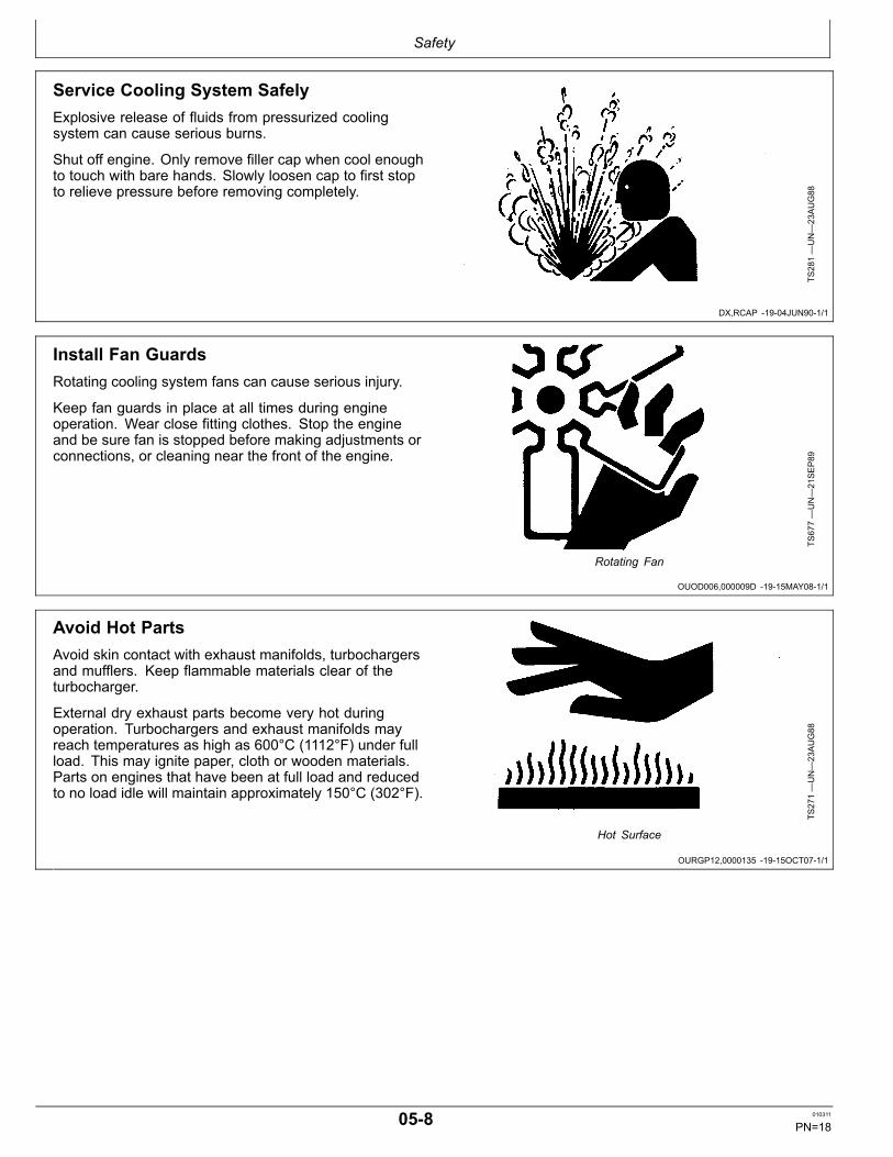
Service Cooling System SafelyExplosive release of fluids from pressurized coolingsystem can cause serious burns.
Shut off engine. Only remove filler cap when cool enoughto touch with bare hands. Slowly loosen cap to first stopto relieve pressure before removing completely.
TS281—UN—23AUG88
Install Fan GuardsRotating cooling system fans can cause serious injury.
Keep fan guards in place at all times during engineoperation. Wear close fitting clothes. Stop the engineand be sure fan is stopped before making adjustments orconnections, or cleaning near the front of the engine.
TS677—UN—21SEP89
Rotating Fan
Avoid Hot PartsAvoid skin contact with exhaust manifolds, turbochargersand mufflers. Keep flammable materials clear of theturbocharger.
External dry exhaust parts become very hot duringoperation. Turbochargers and exhaust manifolds mayreach temperatures as high as 600°C (1112°F) under fullload. This may ignite paper, cloth or wooden materials.Parts on engines that have been at full load and reducedto no load idle will maintain approximately 150°C (302°F).
TS271—UN—23AUG88
Hot Surface
058 010311
PN=18

Safety
DX,DUST 1915MAR911/1
DX,CLEAN 1904JUN901/1
DX,LIGHT 1904JUN901/1
Avoid Harmful Asbestos DustAvoid breathing dust that may be generated whenhandling components containing asbestos fibers. Inhaledasbestos fibers may cause lung cancer.
Components in products that may contain asbestosfibers are brake pads, brake band and lining assemblies,clutch plates, and some gaskets. The asbestos used inthese components is usually found in a resin or sealed insome way. Normal handling is not hazardous as long asairborne dust containing asbestos is not generated.
Avoid creating dust. Never use compressed air forcleaning. Avoid brushing or grinding material containingasbestos. When servicing, wear an approved respirator.A special vacuum cleaner is recommended to cleanasbestos. If not available, apply a mist of oil or water onthe material containing asbestos.
TS220—UN—23AUG88
Keep bystanders away from the area.
Work in Clean AreaBefore starting a job:
• Clean work area and machine.• Make sure you have all necessary tools to do your job.• Have the right parts on hand.• Read all instructions thoroughly; do not attemptshortcuts.
T6642E
J—UN—18OCT88
Illuminate Work Area SafelyIlluminate your work area adequately but safely. Usea portable safety light for working inside or under themachine. Make sure the bulb is enclosed by a wire cage.The hot filament of an accidentally broken bulb can ignitespilled fuel or oil.
TS223—UN—23AUG88
059 010311
PN=19

Safety
DX,SPARKS 1903MAR931/1
Continued on next page DPSG,OUO1004,2758 1915OCT071/2
Prevent Battery ExplosionsKeep sparks, lighted matches, and open flame away fromthe top of battery. Battery gas can explode.
Never check battery charge by placing a metal objectacross the posts. Use a voltmeter or hydrometer.
Do not charge a frozen battery; it may explode. Warmbattery to 16°C (60°F).
TS204—UN—23AUG88
Handling Batteries Safely
CAUTION: Battery gas can explode. Keep sparksand flames away from batteries. Use a flashlightto check battery electrolyte level.
Never check battery charge by placinga metal object across the posts. Use avoltmeter or hydrometer.
Always remove grounded (—) battery clampfirst and replace it last.
TS204—UN—23AUG88
Explosion
0510 010311
PN=20
Safety
DPSG,OUO1004,2758 1915OCT072/2
DX,SPRAY 1916APR921/1
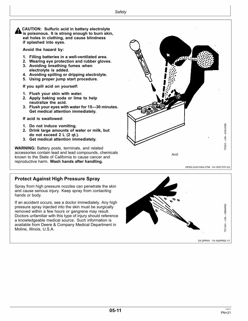
CAUTION: Sulfuric acid in battery electrolyteis poisonous. It is strong enough to burn skin,eat holes in clothing, and cause blindnessif splashed into eyes.
Avoid the hazard by:
1. Filling batteries in a wellventilated area.2. Wearing eye protection and rubber gloves.3. Avoiding breathing fumes when
electrolyte is added.4. Avoiding spilling or dripping electrolyte.5. Using proper jump start procedure.
If you spill acid on yourself:
1. Flush your skin with water.2. Apply baking soda or lime to help
neutralize the acid.3. Flush your eyes with water for 15—30 minutes.
Get medical attention immediately.
If acid is swallowed:
1. Do not induce vomiting.2. Drink large amounts of water or milk, but
do not exceed 2 L (2 qt.).3. Get medical attention immediately.
WARNING: Battery posts, terminals, and relatedaccessories contain lead and lead compounds, chemicalsknown to the State of California to cause cancer andreproductive harm. Wash hands after handling.
TS203—UN—23AUG88
Acid
Protect Against High Pressure SpraySpray from high pressure nozzles can penetrate the skinand cause serious injury. Keep spray from contactinghands or body.
If an accident occurs, see a doctor immediately. Any highpressure spray injected into the skin must be surgicallyremoved within a few hours or gangrene may result.Doctors unfamiliar with this type of injury should referencea knowledgeable medical source. Such information isavailable from Deere & Company Medical Department inMoline, Illinois, U.S.A.
TS1343
—UN—18MAR92
0511 010311
PN=21

Safety
DX,LIFT 1904JUN901/1
DX,REPAIR 1917FEB991/1
DX,DRAIN 1903MAR931/1
Use Proper Lifting EquipmentLifting heavy components incorrectly can cause severeinjury or machine damage.
Follow recommended procedure for removal andinstallation of components in the manual.
TS226—UN—23AUG88
Use Proper ToolsUse tools appropriate to the work. Makeshift tools andprocedures can create safety hazards.
Use power tools only to loosen threaded parts andfasteners.
For loosening and tightening hardware, use the correctsize tools. DO NOT use U.S. measurement tools onmetric fasteners. Avoid bodily injury caused by slippingwrenches.
Use only service parts meeting John Deere specifications. TS779—UN—08NOV89
Dispose of Waste ProperlyImproperly disposing of waste can threaten theenvironment and ecology. Potentially harmful waste usedwith John Deere equipment include such items as oil, fuel,coolant, brake fluid, filters, and batteries.
Use leakproof containers when draining fluids. Do not usefood or beverage containers that may mislead someoneinto drinking from them.
Do not pour waste onto the ground, down a drain, or intoany water source.
Air conditioning refrigerants escaping into the air candamage the Earth’s atmosphere. Government regulationsmay require a certified air conditioning service center torecover and recycle used air conditioning refrigerants.
Inquire on the proper way to recycle or dispose of wastefrom your local environmental or recycling center, or fromyour John Deere dealer.
TS1133
—UN—26NOV90
0512 010311
PN=22

Fuels, Lubricants, and Coolant
DX,FUEL1 1903AUG091/1
DX,FUEL5 1905OCT071/1
Diesel Fuel
Consult your local fuel distributor for properties of thediesel fuel available in your area.
In general, diesel fuels are blended to satisfy the lowtemperature requirements of the geographical area inwhich they are marketed.
Diesel fuels specified to EN 590 or ASTM D975 arerecommended. Renewable diesel fuel produced byhydrotreating animal fats and vegetable oils is basicallyidentical to petroleum diesel fuel. Renewable diesel thatmeets EN 590 or ASTM D975 is acceptable for use at allpercentage mixture levels.
Required Fuel Properties
In all cases, the fuel shall meet the following properties:
Cetane number of 43 minimum. Cetane number greaterthan 47 is preferred, especially for temperatures below–20°C (–4°F) or elevations above 1500 m (5000 ft).
Cold Filter Plugging Point (CFPP) should be at least 5°C(9°F) below the expected lowest temperature or CloudPoint below the expected lowest ambient temperature.
Fuel lubricity should pass a maximum scar diameter of0.45 mm as measured by ASTM D6079 or ISO 121561.
Sulfur Content for Interim Tier 4 and EUStage IIIB Engines
• Diesel fuel quality and fuel sulfur content must complywith all existing emissions regulations for the area inwhich the engine operates.• Use ONLY ultra low sulfur diesel (ULSD) fuel with amaximum of 0.0015% (15 mg/kg) sulfur content.
Sulfur Content for Other Engines
• Diesel fuel quality and fuel sulfur content must complywith all existing emissions regulations for the area inwhich the engine operates.• Use of diesel fuel with sulfur content less than 0.10%(1000 mg/kg) is STRONGLY recommended.• Use of diesel fuel with sulfur content 0.10% (1000mg/kg) to 0.50% (5000 mg/kg) may result in REDUCEDoil and filter change intervals. Refer to table in DieselEngine Oil and Filter Service Intervals.• BEFORE using diesel fuel with sulfur content greaterthan 0.50% (5000 mg/kg), contact your John Deeredealer.
IMPORTANT: Do not mix used diesel engine oil or anyother type of lubricating oil with diesel fuel.
Improper fuel additive usage may cause damageon fuel injection equipment of diesel engines.
Lubricity of Diesel Fuel
Most diesel fuels manufactured in the United States,Canada, and the European Union have adequate lubricityto ensure proper operation and durability of fuel injectionsystem components. However, diesel fuels manufacturedin some areas of the world may lack the necessarylubricity.
IMPORTANT: Make sure the diesel fuel usedin your machine demonstrates goodlubricity characteristics.
Fuel lubricity should pass a maximum scar diameter of0.45 mm as measured by ASTM D6079 or ISO 121561.
If fuel of low or unknown lubricity is used, add John DeerePREMIUM DIESEL FUEL CONDITIONER (or equivalent)at the specified concentration.
Lubricity of Biodiesel Fuel
Significant improvement in lubricity can occur withbiodiesel blends up to B20. The gain in lubricity above a20% blend is limited.
101 010311
PN=23

Fuels, Lubricants, and Coolant
DX,FUEL4 1919DEC031/1
DX,FUEL6 1914NOV051/1
Handling and Storing Diesel Fuel
CAUTION: Handle fuel carefully. Do not fill thefuel tank when engine is running.
DO NOT smoke while you fill the fuel tankor service the fuel system.
Fill the fuel tank at the end of each day’s operation toprevent water condensation and freezing during coldweather.
Keep all storage tanks as full as practicable to minimizecondensation.
Ensure that all fuel tank caps and covers are installedproperly to prevent moisture from entering.
Monitor water content of the fuel regularly.
When using biodiesel fuel, the fuel filter may require morefrequent replacement due to premature plugging.
Check engine oil level daily prior to starting engine. Arising oil level may indicate fuel dilution of the engine oil.
IMPORTANT: The fuel tank is vented through thefiller cap. If a new filler cap is required, alwaysreplace it with an original vented cap.
When fuel is stored for an extended period or if there is aslow turnover of fuel, add a fuel conditioner to stabilize thefuel and prevent water condensation. Contact your fuelsupplier for recommendations.
Testing Diesel FuelDIESELSCAN™ is a John Deere fuel analysis programthat can be used to monitor the quality of your fuel. TheDIESELSCAN analysis verifies fuel type, cleanliness,
water content, suitability for cold weather operation, andwhether the fuel meets specifications.
Check with your John Deere dealer for availability ofDIESELSCAN kits.
DIESELSCAN is a trademark of Deere & Company
102 010311
PN=24

Fuels, Lubricants, and Coolant
DX,FUEL7 1904OCT071/1
Biodiesel Fuel
Biodiesel is a fuel comprised of monoalkyl esters of longchain fatty acids derived from vegetable oils or animalfats. Biodiesel blends are biodiesel mixed with petroleumdiesel fuel on a volume basis.
Biodiesel users in the U.S. are strongly encouraged topurchase biodiesel blends from a BQ9000 CertifiedMarketer and sourced from a BQ9000 AccreditedProducer (as certified by the National Biodiesel Board).Certified Marketers and Accredited Producers can befound at the following website: http://www.bq9000.org.
While 5% blends are preferred (B5), biodieselconcentrations up to a 20% blend (B20) in petroleumdiesel fuel can be used in all John Deere engines.Biodiesel blends up to B20 can be used ONLY if thebiodiesel (100% biodiesel or B100) meets ASTM D6751(US), EN 14214 (EU), or equivalent specification. Expecta 2% reduction in power and a 3% reduction in fueleconomy when using B20.
John Deere approved fuel conditioners containingdetergent/dispersant additives are recommended whenusing lower biodiesel blends, but are required when usingblends of B20 or greater.
John Deere engines can also operate on biodiesel blendsabove B20 (up to 100% biodiesel) ONLY if the biodieselmeets the EN 14214 specification (primarily available inEurope). Engines operating on biodiesel blends aboveB20 may not fully comply with all applicable emissionsregulations. Expect up to a 12% reduction in powerand an 18% reduction in fuel economy when using100% biodiesel. John Deere approved fuel conditionerscontaining detergent/dispersant additives are required.
The petroleum diesel portion of biodiesel blends mustmeet the requirements of ASTM D975 (US) or EN 590(EU) commercial standards.
Biodiesel blends up to B20 must be used within 90 days ofthe date of biodiesel manufacture. Biodiesel blends fromB21 to B100 must be used within 45 days of the date ofbiodiesel manufacture.
Request a certificate of analysis from your fuel distributorto ensure that the fuel is compliant with the abovespecifications.
Consult your John Deere dealer for approved biodieselfuel conditioners to improve storage and performancewith biodiesel fuels.
When using biodiesel fuel, the engine oil level must bechecked daily. If oil becomes diluted with fuel, shorten oilchange intervals. Refer to Diesel Engine Oil and FilterService Intervals for more details regarding biodiesel andengine oil change intervals.
The following must be considered when using biodieselblends up to B20:
• Cold weather flow degradation• Stability and storage issues (moisture absorption,oxidation, microbial growth)• Possible filter restriction and plugging (usually aproblem when first switching to biodiesel on usedengines.)• Possible fuel leakage through seals and hoses• Possible reduction of service life of engine componentsThe following must also be considered when usingbiodiesel blends above B20.
• Possible coking and/or blocked injector nozzles,resulting in power loss and engine misfire if JohnDeere approved fuel conditioners containingdetergent/dispersant additives are not used• Possible crankcase oil dilution, requiring more frequentoil changes• Possible corrosion of fuel injection equipment• Possible lacquering and/or seizure of internalcomponents• Possible formation of sludge and sediments• Possible thermal oxidation of fuel at elevatedtemperatures• Possible elastomer seal and gasket materialdegradation ( primarily an issue with older engines)• Possible compatibility issues with other materials(including copper, lead, zinc, tin, brass, and bronze)used in fuel systems and fuel handling equipment• Possible reduction in water separator efficiency• Potential high acid levels within fuel system• Possible damage to paint if exposed to biodieselIMPORTANT: Raw pressed vegetable oils are
NOT acceptable for use as fuel in anyconcentration in John Deere engines. Theiruse could cause engine failure.
103 010311
PN=25

Fuels, Lubricants, and Coolant
DX,FUEL10 1903AUG091/1
Minimizing the Effect of Cold Weather on Diesel Engines
John Deere diesel engines are designed to operateeffectively in cold weather.
However, for effective starting and coldweather operation,a little extra care is necessary. The following informationoutlines steps that can minimize the effect that coldweather may have on starting and operation of yourengine. See your John Deere dealer for additionalinformation and local availability of coldweather aids.
Use Winter Grade Fuel
When temperatures fall below 0 °C (32 °F), wintergrade fuel (No. 1D in North America) is best suited forcoldweather operation. Winter grade fuel has a lowercloud point and a lower pour point.
Cloud point is the temperature at which wax will begin toform in the fuel and this wax causes fuel filters to plug.Pour point is the lowest temperature at which movementof the fuel is observed.
NOTE: On an average, winter grade diesel fuel has a lowerBTU (heat content) rating. Using winter grade fuelmay reduce power and fuel efficiency, but should notcause any other engine performance effects. Checkthe grade of fuel being used before troubleshootingfor lowpower complaints in coldweather operation.
Air Intake Heater
An air intake heater is an available option for someengines to aid cold weather starting.
Ether
An ether port on the intake is available to aid cold weatherstarting.
CAUTION: Ether is highly flammable. Do notuse ether when starting an engine equippedwith glow plugs or an air intake heater.
Coolant Heater
An engine block heater (coolant heater) is an availableoption to aid cold weather starting.
Seasonal Viscosity Oil and Proper CoolantConcentration
Use seasonal grade viscosity engine oil based on theexpected air temperature range between oil changesand a proper concentration of low silicate antifreeze asrecommended. (See DIESEL ENGINE OIL and ENGINECOOLANT requirements in this section.)
Diesel Fuel Flow Additive
Use John Deere PREMIUM DIESEL FUELCONDITIONER (winter formula), which contains antigel
chemistry, or equivalent fuel conditioner to treat nonwintergrade fuel (No. 2D in North America) during thecoldweather season. This generally extends operabilityto about 10 °C (18 °F) below the fuel cloud point. Foroperability at even lower temperatures, use winter gradefuel.
IMPORTANT: Treat fuel when outside temperaturedrops below 0 °C (32 °F). For best results, usewith untreated fuel. Follow all recommendedinstructions on label.
BioDiesel
When operating with biodiesel blends, wax formation canoccur at warmer temperatures. Begin using John DeerePREMIUM BIODIESEL FUEL CONDITIONER (winterformula) at 5 °C (41 °F) to treat biodiesel fuels duringthe coldweather season. Use B5 or lower blends attemperatures below 0 °C (32 °F). Use only winter gradepetroleum diesel fuel at temperatures below 10 °C (14°F).
Winterfronts
Use of fabric, cardboard, or solid winterfronts is notrecommended with any John Deere engine. Their usecan result in excessive engine coolant, oil, and chargeair temperatures. This can lead to reduced engine life,loss of power and poor fuel economy. Winterfronts mayalso put abnormal stress on fan and fan drive componentspotentially causing premature failures.
If winterfronts are used, they should never totally closeoff the grill frontal area. Approximately 25% area in thecenter of the grill should remain open at all times. At notime should the air blockage device be applied directlyto the radiator core.
Radiator Shutters
If equipped with a thermostatically controlled radiatorshutter system, this system should be regulated in sucha way that the shutters are completely open by the timethe coolant reaches 93 °C (200 °F) to prevent excessiveintake manifold temperatures. Manually controlledsystems are not recommended.
If airtoair aftercooling is used, the shutters must becompletely open by the time the intake manifold airtemperature reaches the maximum allowable temperatureout of the charge air cooler.
For more information, see your John Deere dealer.
104 010311
PN=26

Fuels, Lubricants, and Coolant
DX,ENOIL4 1903AUG091/1
Diesel Engine BreakIn Oil
New engines are filled at the factory with either JohnDeere BreakIn™ or BreakIn™ Plus Engine Oil. Duringthe breakin period, add John Deere BreakIn™ orBreakIn™ Plus Engine Oil, respectively, as needed tomaintain the specified oil level.
Operate the engine under various conditions, particularlyheavy loads with minimal idling, to help seat enginecomponents properly.
Change the oil and filter at 100 hours maximum forBreakIn™ Oil or 500 hours maximum for BreakIn™ PlusOil during the initial operation of a new or rebuilt engine.
After engine overhaul, fill the engine with either JohnDeere BreakIn™ or BreakIn™ Plus Engine Oil.
If John Deere BreakIn™ or BreakIn™ Plus Engine Oil isnot available, use a 10W30 diesel engine oil meeting oneof the following during the first 100 hours of operation:
• API Service Classification CE• API Service Classification CD• API Service Classification CC• ACEA Oil Sequence E2• ACEA Oil Sequence E1
IMPORTANT: Do not use Plus50™ II, Plus50 orengine oils meeting any of the following for theinitial breakin of a new or rebuilt engine:
API CJ4 ACEA E9API CI4 PLUS ACEA E7API CI4 ACEA E6API CH4 ACEA E5API CG4 ACEA E4API CF4 ACEA E3API CF2API CF
These oils will not allow the engine tobreak in properly.
John Deere BreakIn™ Plus Engine Oil can be used forall John Deere diesel engines at all emission certificationlevels.
After the breakin period, use John Deere Plus50 ™II, John Deere Plus50, or other diesel engine oil asrecommended in this manual.
BreakIn is a trademark of Deere & Company.Plus50 is a trademark of Deere & Company.
105 010311
PN=27

Fuels, Lubricants, and Coolant
DX,ENOIL11 1903AUG091/1
Diesel Engine OilUse oil viscosity based on the expected air temperaturerange during the period between oil changes.
John Deere Plus50™ II oil is preferred.
John Deere Plus50™ is also recommended.
Other oils may be used if they meet one or more of thefollowing:
• John Deere TorqGard Supreme™• API Service Category CJ4• API Service Category CI4 PLUS• API Service Category CI4• ACEA Oil Sequence E9• ACEA Oil Sequence E7• ACEA Oil Sequence E6• ACEA Oil Sequence E5• ACEA Oil Sequence E4
Multiviscosity diesel engine oils are preferred.
Diesel fuel quality and fuel sulfur content must complywith all existing emissions regulations for the area inwhich the engine operates.
DO NOT use diesel fuel with sulfur content greater than1.0% (10 000 mg/kg).
SA
E 1
5W-4
0
SA
E 1
0W-4
0
SA
E 1
0W-3
0
SA
E 0
W-4
0
SA
E 5
W-3
0
50 Co
40 Co
30 Co
20 Co
10 Co
0 C o
-10 Co
-20 Co
-30 Co
-40 Co
122 Fo
50 Fo
32 Fo
14 Fo
-4 Fo
-22 Fo
-40 Fo
104 Fo
68 Fo
86 Fo
TS1691
—UN—18JU
L07
Oil Viscosities for Air Temperature Ranges
Plus50 is a trademark of Deere & CompanyTorqGard Supreme is a trademark of Deere & Company
106 010311
PN=28

Fuels, Lubricants, and Coolant
Continued on next page OURGP11,000004D 1918FEB081/2
Diesel Engine Oil and Filter Service Intervals
The oil and filter service intervals in the following chartsshould be used as guidelines. Actual service intervalsdepend on operation and maintenance practices. Use oilanalysis to determine the actual useful life of the oil and toaid in selection of the proper oil and filter service interval.
Oil and filter service intervals are based on a combinationof oil pan capacity, type of engine oil and filter used, andsulfur content of the diesel fuel.
Diesel fuel sulfur level will affect engine oil and filterservice intervals. Higher fuel sulfur levels reduce oil andfilter service intervals as shown in the table:
• Use of diesel fuel with sulfur content less than 0.10%(1000 ppm ) is strongly recommended.• Use of diesel fuel with sulfur content 0.10% (1000 ppm)to 0.50% (5000 ppm) may result in REDUCED oil andfilter change intervals as shown in the table.• BEFORE using diesel fuel with sulfur content greaterthan 0.50% (5000 ppm), contact your John Deeredealer.• DO NOT use diesel fuel with sulfur content greater than1.00% (10 000 ppm).
Oil types (premium or standard) in the tables include:
• “Premium Oils” include John Deere PLUS50™, ACEAE7, or ACEA E6 oils.• “Standard Oils” include John Deere TORQGARDSUPREME™, API CJ4, API CI4 PLUS, API CI4,ACEA E5, or ACEA E4 oils.Use of lower specification oils in U.S. Tier 3 and EUStage IIIA engines may result in premature enginefailure.
NOTE: The 500 hour extended oil and filterchange interval is allowed only if ALL thefollowing conditions are met:
• Engine equipped with an extended drain interval oil pan.
• Use of diesel fuel with sulfur content less than 0.50%(5000 ppm)• Use of premium oil John Deere PLUS50, ACEA E7or ACEA E6• Perform engine oil analysis to determine the actualextended service life of ACEA E7 and ACEA E6 oils.• Use of the approved John Deere oil filterRefer to the charts on the following pages to find theproper oil and filter service interval for your engine.
Using Charts to Find Oil and Filter Service Interval
1. Determine your engine model and power rating andfind it in the left column of 6135 chart.
2. Locate your engine oil pan option code (19__) onengine label.
3. In the chart column under your oil pan code,select whether you use premium oil (PLUS50™ orequivalent) or standard grade oil.
4. Determine the sulfur content of your diesel fuel.
5. Now you can find the proper oil and filter changeinterval by lining up your power level and fuel sulfurcontent with oil pan/oil type column. The numberindicates how frequently your oil and filter should bechanged.
Example:
• Engine Model 6135• Engine Power 261kW (350 hp)• Oil Pan Code 1917• Oil Type Premium• Oil Filter John Deere approved• Fuel Sulfur Level 0.100.20 (10002000 ppm)In the 6135 chart under 261kW Power Rating, select theline for 0.100.20 “Fuel Sulfur Content” and move acrossto column for 1917 “oil pan option code”, select “Prem Oil”and read 500 hour oil change interval.
6135 (13.5 L) Engine Oil and Filter Service Intervals in Hours of OperationPower Rating Oil PanskW (hp) Fuel Sulfur Content a 1915, 1917, 1918 1914
Interval IntervalStd Oil PremOil Std Oil PremOil
Industrial Ratings261 (350) Less Than 0.10% (1000 ppm) 250 500 250 500
0.10% 0.20% (1000 2000 ppm) 250 500 250 5000.20% 0.50% (2000 5000 ppm) 200 300 250 500
298336 (400451) Less Than 0.10% (1000 ppm) 250 500 250 5000.10% 0.20% (1000 2000 ppm) 200 300 250 5000.20% 0.50% (2000 5000 ppm) 150 250 200 300
373410 (500550) Less Than 0.10% (1000 ppm) 250 375 250 5000.10% 0.20% (1000 2000 ppm) 200 300 250 5000.20% 0.50% (2000 5000 ppm) 150 250 200 300
448 (600) Less Than 0.10% (1000 ppm) None None 250 500
107 010311
PN=29

Fuels, Lubricants, and Coolant
OURGP11,000004D 1918FEB082/2
DX,LUBMIX 1918MAR961/1
6135 (13.5 L) Engine Oil and Filter Service Intervals in Hours of OperationPower Rating Oil PanskW (hp) Fuel Sulfur Content a 1915, 1917, 1918 1914
Interval Interval0.10% 0.20% (1000 2000 ppm) None None 200 3000.20% 0.50% (2000 5000 ppm) None None 150 250
GenSet Ratings345401 (463538) Less Than 0.10% (1000 ppm) 250 375 250 500
0.10% 0.20% (1000 2000 ppm) 200 300 250 5000.20% 0.50% (2000 5000 ppm) 150 250 200 300
460 (617) Less Than 0.10% (1000 ppm) 250 375 250 5000.10% 0.20% (1000 2000 ppm) 200 300 200 3000.20% 0.50% (2000 5000 ppm) 150 250 150 250
Perform engine oil analysis to determine the actual extended service life of ACEA E7 and ACEA E6 oils.a BEFORE using diesel fuel with sulfur content greater than 0.50% (5000 ppm), contact your John Deeredealer. (Dealer to reference DTAC Solution 73203)
PLUS50 is a trademark of Deere & CompanyTORQGARD SUPREME is a trademark of Deere & Company
Mixing of Lubricants
In general, avoid mixing different brands or types of oil.Oil manufacturers blend additives in their oils to meetcertain specifications and performance requirements.
Mixing different oils can interfere with the properfunctioning of these additives and degrade lubricantperformance.
Consult your John Deere dealer to obtain specificinformation and recommendations.
108 010311
PN=30

Fuels, Lubricants, and Coolant
DX,OILSCAN 1902DEC021/1
DX,ALTER 1911NOV091/1
DX,LUBST 1918MAR961/1
OILSCAN ™ and COOLSCAN ™OILSCAN ™ and COOLSCAN ™ are John Deeresampling programs to help you monitor machineperformance and identify potential problems before theycause serious damage.
Oil and coolant samples should be taken from eachsystem prior to its recommended change interval.
Check with your John Deere dealer for the availability ofOILSCAN ™ and COOLSCAN ™ kits.
T6828A
B—UN—15JU
N89
T6829A
B—UN—18OCT88
OILSCAN is a trademark of Deere & Company.COOLSCAN is a trademark of Deere & Company.
Alternative and Synthetic Lubricants
Conditions in certain geographical areas may requirelubricant recommendations different from those printed inthis manual.
Some John Deere brand coolants and lubricants may notbe available in your location.
Synthetic lubricants may be used if they meet theperformance requirements as shown in this manual.
The temperature limits and service intervals shown in thismanual apply to both conventional and synthetic oils.
Rerefined base stock products may be used if thefinished lubricant meets the performance requirements.
Avoid mixing different brands or types of oils. Oilmanufacturers blend base stock and additives tocreate their oils and to meet certain specifications andperformance requirements. Mixing different oils caninterfere with proper functioning of these formulations anddegrade lubricant performance.
Consult your authorized John Deere dealer to obtainspecific information and recommendations.
Lubricant Storage
Your equipment can operate at top efficiency only whenclean lubricants are used.
Use clean containers to handle all lubricants.
Whenever possible, store lubricants and containersin an area protected from dust, moisture, and othercontamination. Store containers on their side to avoidwater and dirt accumulation.
Make certain that all containers are properly marked toidentify their contents.
Properly dispose of all old containers and any residuallubricant they may contain.
109 010311
PN=31

Fuels, Lubricants, and Coolant
DX,FILT 1918MAR961/1
DX,COOL3 1903NOV081/1
Oil FiltersFiltration of oils is critical to proper operation andlubrication.
Always change filters regularly as specified in this manual.
Use filters meeting John Deere performancespecifications.
Heavy Duty Diesel Engine Coolant
The engine cooling system is filled to provide yearroundprotection against corrosion and cylinder liner pitting, andwinter freeze protection to 37°C (34°F). If protection atlower temperatures is required, consult your John Deeredealer for recommendations.
John Deere COOLGARD™ II Premix Coolantis preferred.
John Deere COOLGARD II Premix is available in aconcentration of 50% ethylene glycol.
Additional Recommended Coolants
The following engine coolants are also recommended:
• John Deere COOLGARD II Concentrate in a 40% to60% mixture of concentrate with quality water.• John Deere COOLGARD Premix (available in aconcentration of 50% ethylene glycol).• John Deere COOLGARD Concentrate in a 40% to 60%mixture of concentrate with quality water.• John Deere COOLGARD PG Premix (available in aconcentration of 55% propylene glycol).
John Deere COOLGARD II Premix and COOLGARD IIConcentrate coolants do not require use of supplementalcoolant additives.
John Deere COOLGARD Premix, COOLGARDConcentrate, and COOLGARD PG Premix do not requireuse of supplemental coolant additives, except for periodicreplenishment of additives during the drain interval.
Use John Deere COOLGARD PG Premix when anontoxic coolant formulation is required.
Other Coolants
It is possible that John Deere COOLGARD II,COOLGARD, and COOLGARD PG coolants are
unavailable in the geographical area where service isperformed.
If these coolants are unavailable, use a coolantconcentrate or prediluted coolant intended for use withheavy duty diesel engines and with a minimum of thefollowing chemical and physical properties:
• Is formulated with a quality nitritefree additive package.• Provides cylinder liner cavitation protection according toeither the John Deere Cavitation Test Method or a fleetstudy run at or above 60% load capacity.• Protects the cooling system metals (cast iron, aluminumalloys, and copper alloys such as brass) from corrosion.
The additive package must be part of one of the followingcoolant mixtures:
• ethylene glycol or propylene glycol base prediluted(40% to 60%) heavy duty coolant• ethylene glycol or propylene glycol base heavy dutycoolant concentrate in a 40% to 60% mixture ofconcentrate with quality water
Water Quality
Water quality is important to the performance of thecooling system. Distilled, deionized, or demineralizedwater is recommended for mixing with ethylene glycol andpropylene glycol base engine coolant concentrate.
IMPORTANT: Do not use cooling system sealingadditives or antifreeze that containssealing additives.
Do not mix ethylene glycol and propyleneglycol base coolants.
Do not use coolants that contain nitrites.
COOLGARD is a trademark of Deere & Company
1010 010311
PN=32

Fuels, Lubricants, and Coolant
DX,COOL4 1903NOV081/1
DX,COOL11 1908JAN091/1
Supplemental Coolant Additives
Some coolant additives will gradually deplete duringengine operation. For John Deere COOLGARD™Premix, COOLGARD Concentrate, or John DeereCOOLGARD PG Premix, replenish coolant additivesbetween drain intervals by adding a supplemental coolantadditive as determined necessary by coolant testing.
John Deere LIQUID COOLANT CONDITIONER isrecommended as a supplemental coolant additive for JohnDeere COOLGARD Premix, COOLGARD Concentrate,and COOLGARD PG Premix.
John Deere LIQUID COOLANT CONDITIONER isnot designed for use with COOLGARD II Premix orCOOLGARD II Concentrate.
IMPORTANT: Do not add a supplemental coolantadditive when the cooling system is drainedand refilled with any of the following:
• John Deere COOLGARD II• John Deere COOLGARD• John Deere COOLGARD PG
If other coolants are used, consult the coolant supplierand follow the manufacturer’s recommendation for use ofsupplemental coolant additives.
The use of nonrecommended supplemental coolantadditives may result in additive dropout and gelation ofthe coolant.
Add the manufacturer’s recommended concentration ofsupplemental coolant additive. DO NOT add more thanthe recommended amount.
COOLGARD is a trademark of Deere & Company
Drain Intervals for Diesel Engine Coolant
Drain and flush the cooling system and refill with freshcoolant at the indicated interval, which varies with thecoolant used.
John Deere COOLGARD™ II Premix and COOLGARDII Concentrate are maintenance free coolants for up to 6years or 6000 hours of operation, provided that the coolingsystem is topped off using only John Deere COOLGARDII Premix. Test the coolant condition annually withCoolant Test Strips designed for use with John DeereCOOLGARD II coolants. If the test strip chart indicatesthat additive is required, add John Deere COOLGARD IICOOLANT EXTENDER as directed.
When John Deere COOLGARD Premix, COOLGARDConcentrate or John Deere COOLGARD PG Premixcoolants are used, the drain interval may be extendedto 5 years or 5000 hours of operation, provided that thecoolant is tested annually AND additives are replenished,as needed, by adding a supplemental coolant additive.
If John Deere COOLGARD II Premix or COOLGARDII Concentrate is used, but the coolant is not tested OR
additives are not replenished by adding John DeereCOOLGARD II COOLANT EXTENDER, the drain intervalis 4 years or 4000 hours of operation. This drain intervalonly applies to COOLGARD II coolants that have beenmaintained within a 40% to 60% mixture of concentratewith quality water.
If John Deere COOLGARD Premix, COOLGARDConcentrate, or COOLGARD PG Premix is used, but thecoolant is not tested OR additives are not replenishedby adding a supplemental coolant additive, the draininterval is 3 years or 3000 hours of operation. Thisdrain interval only applies to COOLGARD Premix,COOLGARD Concentrate, and COOLGARD PG Premixthat have been maintained within a 40% to 60% mixtureof concentrate with quality water.
If a coolant other than COOLGARD II, COOLGARD, orCOOLGARD PG is used, reduce the drain interval to 2years or 2000 hours of operation.
COOLGARD is a trademark of Deere & Company
1011 010311
PN=33

Fuels, Lubricants, and Coolant
DX,COOL7 1903NOV081/1
Additional Information About Diesel Engine Coolants and John Deere LIQUID COOLANTCONDITIONER
Engine coolants are a combination of three chemicalcomponents: ethylene glycol or propylene glycolantifreeze, inhibiting coolant additives, and quality water.
Coolant Specifications
Some products, including John Deere COOLGARD™Premix coolant, are fully formulated coolants that containall three components in their correct concentrations. Donot add an initial charge of supplemental coolant additivesor water to John Deere COOLGARD Premix.
John Deere COOLGARD Concentrate contains bothethylene glycol and inhibiting coolant additives. MixCOOLGARD Concentrate with quality water, but do notadd an initial charge of supplemental coolant additives.
Replenish Coolant Additives
Some coolant additives will gradually deplete duringengine operation. Periodic replenishment of inhibitors isrequired, even when John Deere COOLGARD Premix,COOLGARD Concentrate, or COOLGARD PG Premix isused. Follow the recommendations in this manual for theuse of supplemental coolant additives.
Why use John Deere LIQUID COOLANTCONDITIONER?
Operating without proper coolant additives will result inincreased corrosion, cylinder liner erosion and pitting, andother damage to the engine and cooling system. A simplemixture of ethylene glycol or propylene glycol and waterwill not give adequate protection.
John Deere LIQUID COOLANT CONDITIONER is anadditive system designed to reduce corrosion, erosion,and pitting when used with nitritecontaining diesel enginecoolants such as John Deere COOLGARD Premix,COOLGARD Concentrate, and COOLGARD PG Premix.Maintaining John Deere COOLGARD coolants withJohn Deere LIQUID COOLANT CONDITIONER providesoptimum protection for up to 5 years or 5000 hours ofoperation.
Avoid Automotivetype Coolants
Never use automotivetype coolants (such as thosemeeting ASTM D3306). These coolants do not containthe correct additives to protect heavyduty diesel engines.They often contain a high concentration of silicates andmay damage the engine or cooling system. Do not treatan automotive engine coolant with a supplemental coolantadditive because the high concentration of additives canresult in additive fallout.
Water Quality
Water quality is important to the performance of thecooling system. Distilled, deionized, or demineralizedwater is recommended for mixing with ethylene glycoland propylene glycol base engine coolant concentrate.All water used in the cooling system should meet thefollowing minimum specifications for quality:Chlorides <40 mg/LSulfates <100 mg/LTotal dissolved solids <340 mg/LTotal hardness <170 mg/LpH 5.5 to 9.0
Freeze Protection
The relative concentrations of glycol and water in theengine coolant determine its freeze protection limit.
Ethylene Glycol Freeze Protection Limit40% 24°C (12°F)50% 37°C (34°F)60% 52°C (62°F)
Propylene Glycol Freeze Protection Limit40% 21°C (6°F)50% 33°C (27°F)60% 49°C (56°F)
DO NOT use a coolantwater mixture greater than 60%ethylene glycol or 60% propylene glycol.
COOLGARD is a trademark of Deere & Company
1012 010311
PN=34

Fuels, Lubricants, and Coolant
DX,COOL9 1903NOV081/1
DX,COOL6 1903NOV081/1
Testing Diesel Engine Coolant
Maintaining adequate concentrations of glycol andinhibiting additives in the coolant is critical to protect theengine and cooling system against freezing, corrosion,and cylinder liner erosion and pitting.
Test the coolant solution at intervals of 12 months or lessand whenever excessive coolant is lost through leaks oroverheating.
Coolant Test Strips
Coolant test strips are available from your John Deeredealer. These test strips provide a simple, effectivemethod to check the freeze point and additive levels ofyour engine coolant.
When Using John Deere COOLGARD II
John Deere COOLGARD™ II Premix and COOLGARDII Concentrate are maintenance free coolants for up to 6years or 6000 hours of operation, provided that the coolingsystem is topped off using only John Deere COOLGARDII Premix coolant. Test the coolant condition annuallywith coolant test strips designed for use with John Deere
COOLGARD II coolants. If the test strip chart indicatesthat additive is required, add John Deere COOLGARD IICOOLANT EXTENDER as directed.
Add only the recommended concentration of John DeereCOOLGARD II COOLANT EXTENDER. DO NOT addmore than the recommended amount.
When Using John Deere COOLGARD
Compare the test strip results to the supplemental coolantadditive (SCA) chart to determine the amount of inhibitingadditives in your coolant and whether more John DeereLIQUID COOLANT CONDITIONER should be added.
Add only the recommended concentration of John DeereLIQUID COOLANT CONDITIONER. DO NOT add morethan the recommended amount.
CoolScan and CoolScan PLUS
For a more thorough evaluation of your coolant, performa CoolScan™ or CoolScan PLUS™ analysis, whereavailable. See your John Deere dealer for information.
COOLGARD is a trademark of Deere & CompanyCoolScan is a trademark of Deere & CompanyCoolScan PLUS is a trademark of Deere & Company
Operating in Warm Temperature Climates
John Deere engines are designed to operate using glycolbase engine coolants.
Always use a recommended glycol base engine coolant,even when operating in geographical areas where freezeprotection is not required.
John Deere COOLGARD™ II Premix is available in aconcentration of 50% ethylene glycol. However, thereare situations in warm temperature climates where acoolant with lower glycol concentration (approximately20% ethylene glycol) has been approved. In these cases,the low glycol formulation has been modified to providethe same level of corrosion inhibitor as John DeereCOOLGARD II Premix (50/50).
IMPORTANT: Water may be used as coolant inemergency situations only.
Foaming, hot surface aluminum and ironcorrosion, scaling, and cavitation will occurwhen water is used as the coolant, even whencoolant conditioners are added.
Drain cooling system and refill withrecommended glycol base engine coolantas soon as possible.
COOLGARD is a trademark of Deere & Company
1013 010311
PN=35
Fuels, Lubricants, and Coolant
RG,RG34710,7543 1909JAN071/1
Disposing of CoolantImproperly disposing of engine coolant can threaten theenvironment and ecology.
Use leakproof containers when draining fluids. Do not usefood or beverage containers that may mislead someoneinto drinking from them.
Do not pour waste onto the ground, down a drain, or intoany water source.
Inquire on the proper way to recycle or dispose of wastefrom your local environmental or recycling center, or fromyour John Deere engine distributor or servicing dealer.
TS1133
—UN—26NOV90
Recycle Waste
1014 010311
PN=36

Instrument Panel and Diagnostic Gauge
Continued on next page OMRGP15,0000120 1912SEP061/3
Instrument Panels
RG13276—UN—28OCT03
FullFeatured Instrument Panel
RG13277—UN—22OCT03
Basic Instrument Panel
A—Diagnostic Gauge/Hour MeterB—TachometerC—Voltmeter (Optional)D—Audible Alarm (Optional)E—Audible Alarm Override
Button
F—Key SwitchG—Override Shutdown Rocker
SwitchH—Bump Enable Rocker SwitchI— Speed Select Rocker SwitchJ—HighLow Speed Select
Rocker Switch
K—Analog Throttle Control(Optional)
L—Oil Pressure GaugeM—Coolant Temperature GaugeN—Menu KeyO—Arrow Keys
P—Enter KeyQ—Amber “WARNING” Indicator
LightR—Red “STOP ENGINE”
Indicator Light
John Deere PowerTech Plus™ OEM Engines havean electronic control system, which has the followingcontrols and gauges as shown. The following informationapplies only to those controls and gauges supplied byJohn Deere. Refer to your engine application manual forspecific guidelines if John Deeresourced controls andinstrumentation are not used.
Following is a brief description of the available optionalelectronic controls and gauges found on John Deereprovided instrument panels. Refer to manufacturer’sliterature for information on controls not provided byDeere.
Instrument Panel (Continued)
A—Diagnostic Gauge/Hour Meter
The diagnostic gauge (A) displays diagnostic troublecodes (DTCs) as they are accessed. Other informationon the engine can be accessed using the touch keys (N,O and P). The hour meter feature shows the operatinghours of the engine and should be used as a guide forscheduling periodic maintenance. If the diagnostic gaugereceives a trouble code from an engine control unit, thecurrent display will switch to a warning or shutdown(depending on the severity of the code) screen that willdisplay the trouble code number, the description of thecode and the corrective action needed.
B—Tachometer
The tachometer (B) indicates engine speed in hundredsof revolutions per minute (rpm).
C—Voltmeter (Optional)
151 010311
PN=37

Instrument Panel and Diagnostic Gauge
Continued on next page OMRGP15,0000120 1912SEP062/3
The voltmeter (C) indicates system battery voltage. Theamber “Warning” light (Q) will illuminate when batteryvoltage is too low for proper operation of the fuel injectionsystem.
D—Audible Alarm (Optional)
The audible alarm (D) will sound whenever any of theseabnormal conditions exist: low oil pressure, high coolanttemperature, waterinfuel, high fuel temperature, or highmanifold temperatures. This includes all signals that lightup the amber “warning” indicator (intermittent alarm) orthe red “stop engine” indicator (steady alarm).
E—Audible Alarm Override Button
The optional audible alarm has an override button (E) thatsilences the audible alarm for approximately two minuteswhen pressed.
F—Key Start Switch
The threeposition key start switch (F) controls the engineelectrical system. When the key switch is turned clockwiseto “START”, the engine will crank. When the engine starts,the key is released and returns to the “ON” (RUN) position.
G—Override Shutdown Rocker Switch
Switch will be present, but may not be active, dependingon engine controller (ECU) options originally selected. Ifswitch is active, pressing the upper half of the overrideshutdown switch (G) will override an engine shutdownsignal. The switch must be pressed within 30 secondsto prevent undesired shutdown of engine. Pressing thisswitch will override the engine shutdown for 30 secondsat a time to move vehicle to a safe location.
H—Bump Speed Enable Rocker Switch
This is a threeposition switch (H) with the center positionas “OFF” (locked). With this switch in the “OFF” position,the speed select switch (I) is also locked, to preventaccidental changes in operating speed. Pressing upperor lower half of switch (H) will unlock or enable the bumpspeed switch to take effect using speed select switch (I).
I—Speed Select Rocker Switch
The speed select switch (I) is used to bump engine speedup (+) or down () in small increments during operation.This switch must be used with the bump speed enableswitch (H) in the unlocked position (top or bottom half ofbutton depressed).
J—HighLow Speed Select Rocker Switch
The highlow speed select switch (J) is used to set theengine operating speeds at slow (turtle) or fast (rabbit).Factory preset idle speeds can also be adjusted usingbump speed enable switch (H) with speed select switch (I).
The basic instrument panel will have the highlow speedselect switch only. Press and hold up (+) or down ()to adjust engine speed as desired. The engine speedselected will not be held in the memory. To adjust enginespeeds, See Changing Engine Speed in Section 20.
How To Select Preset Operating Speeds (BumpSpeeds)
First select Turtle (Slow) or Adj by pressing speed selectswitch (J) to “Turtle” (slow) or “Adj”(center). Then you canpress either the upper or lower portion of the bump speedenable switch (H) to unlock the setting. The bump speedenable must be held down as the speed select switch (J)is used to change the setting by pressing (+) to increasespeed or () to decrease speed.
Once the slow idle speed has been set, the bumpspeed enable switch must be pressed and releasedthree times within two seconds to commit the newoperating speed to memory. If not done, the engine’snew speed will only be effective until the key switch is shutoff. Then the speed will revert back to the previous setting.
The fast idle speed is not adjustable. It will always goback to the factory preset fast idle speed.
K—Analog Throttle Control (Optional)
The throttle control (K) is used to control engine speed.This control is available only on engines with analogthrottle.
L—Engine Oil Pressure Gauge
The oil pressure gauge (L) indicates engine oil pressure.An audible alarm (D) warns the operator if engine oilpressure falls below a safe operating pressure.
M—Engine Coolant Temperature Gauge
The engine coolant temperature gauge (M) indicatesengine coolant temperature. An audible alarm (D) warnsthe operator if coolant temperature rises above the presetsafe operating temperature.
N—Menu Key
The menu key is pressed to either enter or exit the menuscreens on the diagnostic gauge.
O—Arrow Keys
Use the arrow keys (O) to change the display on thewindow of the diagnostic gauge and to access engineperformance data.
Pressing the left arrow to scroll to the left or upward orthe right arrow to scroll to the right or downward. Thiswill allow you to view various engine parameters and anydiagnostic trouble codes that occur.
Refer to the following story for accessing engineinformation on the diagnostic gauge using the touch keys.
P—Enter Key
The enter key is pressed to select the parameter that ishighlighted on the screen.
Q—Amber “WARNING” Indicator Light
152 010311
PN=38
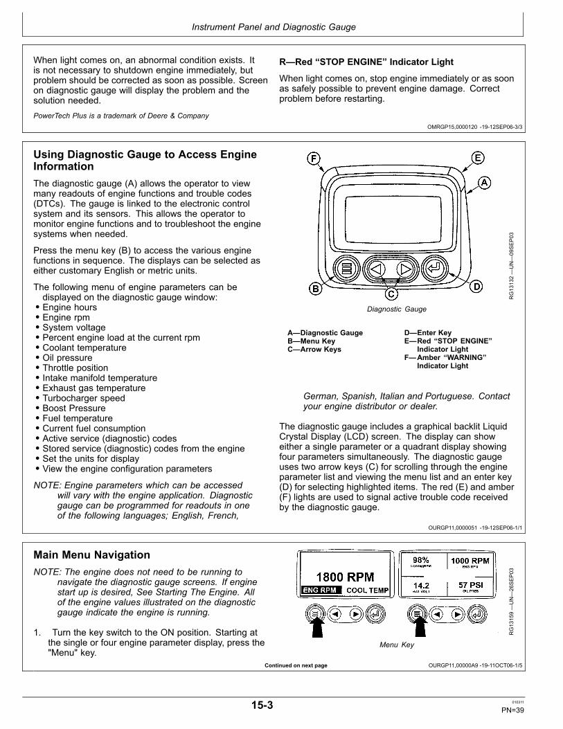
Instrument Panel and Diagnostic Gauge
OMRGP15,0000120 1912SEP063/3
OURGP11,0000051 1912SEP061/1
Continued on next page OURGP11,00000A9 1911OCT061/5
When light comes on, an abnormal condition exists. Itis not necessary to shutdown engine immediately, butproblem should be corrected as soon as possible. Screenon diagnostic gauge will display the problem and thesolution needed.
R—Red “STOP ENGINE” Indicator Light
When light comes on, stop engine immediately or as soonas safely possible to prevent engine damage. Correctproblem before restarting.
PowerTech Plus is a trademark of Deere & Company
Using Diagnostic Gauge to Access EngineInformationThe diagnostic gauge (A) allows the operator to viewmany readouts of engine functions and trouble codes(DTCs). The gauge is linked to the electronic controlsystem and its sensors. This allows the operator tomonitor engine functions and to troubleshoot the enginesystems when needed.
Press the menu key (B) to access the various enginefunctions in sequence. The displays can be selected aseither customary English or metric units.
The following menu of engine parameters can bedisplayed on the diagnostic gauge window:• Engine hours• Engine rpm• System voltage• Percent engine load at the current rpm• Coolant temperature• Oil pressure• Throttle position• Intake manifold temperature• Exhaust gas temperature• Turbocharger speed• Boost Pressure• Fuel temperature• Current fuel consumption• Active service (diagnostic) codes• Stored service (diagnostic) codes from the engine• Set the units for display• View the engine configuration parameters
NOTE: Engine parameters which can be accessedwill vary with the engine application. Diagnosticgauge can be programmed for readouts in oneof the following languages; English, French,
RG13132—UN—09SEP03
Diagnostic Gauge
A—Diagnostic GaugeB—Menu KeyC—Arrow Keys
D—Enter KeyE—Red “STOP ENGINE”
Indicator LightF—Amber “WARNING”
Indicator Light
German, Spanish, Italian and Portuguese. Contactyour engine distributor or dealer.
The diagnostic gauge includes a graphical backlit LiquidCrystal Display (LCD) screen. The display can showeither a single parameter or a quadrant display showingfour parameters simultaneously. The diagnostic gaugeuses two arrow keys (C) for scrolling through the engineparameter list and viewing the menu list and an enter key(D) for selecting highlighted items. The red (E) and amber(F) lights are used to signal active trouble code receivedby the diagnostic gauge.
Main Menu NavigationNOTE: The engine does not need to be running to
navigate the diagnostic gauge screens. If enginestart up is desired, See Starting The Engine. Allof the engine values illustrated on the diagnosticgauge indicate the engine is running.
1. Turn the key switch to the ON position. Starting atthe single or four engine parameter display, press the"Menu" key.
RG13159—UN—26SEP03
Menu Key
153 010311
PN=39

Instrument Panel and Diagnostic Gauge
OURGP11,00000A9 1911OCT062/5
OURGP11,00000A9 1911OCT063/5
Continued on next page OURGP11,00000A9 1911OCT064/5
2. The first seven items of the "Main Menu" will bedisplayed.
RG13160—UN—02OCT03
Menu Display
3. Pressing the "Arrow" keys will scroll through the menuselections.
RG13161—UN—02OCT03
Main Menu Items
4. Pressing the right arrow key will scroll down to revealthe last items of "Main Menu" screen, highlighting thenext item down.
RG13162—UN—26SEP03
Last Items On Main Menu
154 010311
PN=40

Instrument Panel and Diagnostic Gauge
OURGP11,00000A9 1911OCT065/5
OURGP11,00000AB 1912SEP061/6
Continued on next page OURGP11,00000AB 1912SEP062/6
5. Use the arrow keys to scroll to the desired menu itemor press the "Menu Button" to exit the main menu andreturn to the engine parameter display.
RG13163—UN—02OCT03
Use Arrow Buttons To Scroll / Quadrant Display
Engine Configuration DataNOTE: The engine configuration data is a read
only function.
NOTE: The engine does not need to be running tonavigate the diagnostic gauge screens. If enginestart up is desired, See Starting The Engine. Allof the engine values illustrated on the diagnosticgauge indicate the engine is running.
1. Turn the key switch to the ON position. Starting atthe single or four engine parameter display, press the"Menu" key.
RG13159—UN—26SEP03
Menu Key
2. The main menu will be displayed. Use the "Arrow"keys to scroll through the menu until "Engine Config"is highlighted.
RG13164—UN—07OCT03
Select Engine Configuration
155 010311
PN=41

Instrument Panel and Diagnostic Gauge
OURGP11,00000AB 1912SEP063/6
OURGP11,00000AB 1912SEP064/6
Continued on next page OURGP11,00000AB 1912SEP065/6
3. Once "Engine Config" menu item has been highlighted,press the "Enter" key to view the engine configurationdata.
RG13165—UN—02OCT03
Enter Key
4. Use the "Arrow" keys to scroll through the engineconfiguration data.
RG13166—UN—29SEP03
Use Arrow Keys To Scroll
5. Press the "Menu" key to return to the main menu.
RG13167—UN—29SEP03
Return To Main Menu
156 010311
PN=42
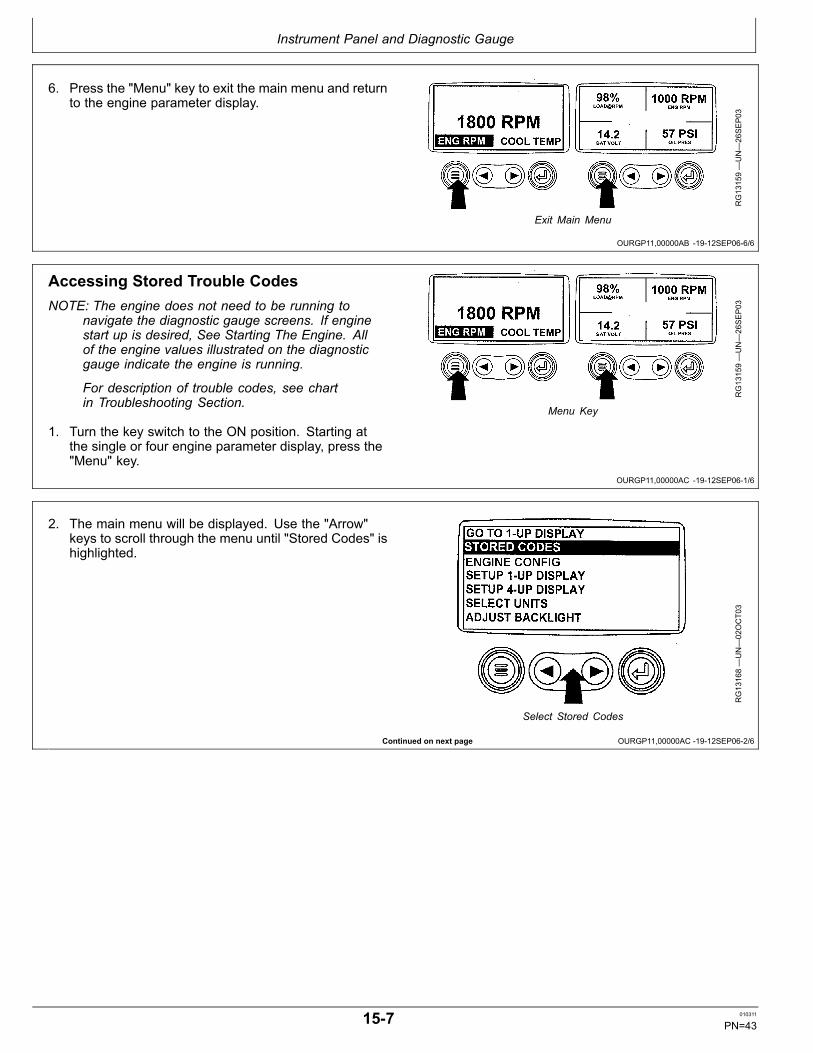
Instrument Panel and Diagnostic Gauge
OURGP11,00000AB 1912SEP066/6
OURGP11,00000AC 1912SEP061/6
Continued on next page OURGP11,00000AC 1912SEP062/6
6. Press the "Menu" key to exit the main menu and returnto the engine parameter display.
RG13159—UN—26SEP03
Exit Main Menu
Accessing Stored Trouble CodesNOTE: The engine does not need to be running to
navigate the diagnostic gauge screens. If enginestart up is desired, See Starting The Engine. Allof the engine values illustrated on the diagnosticgauge indicate the engine is running.
For description of trouble codes, see chartin Troubleshooting Section.
1. Turn the key switch to the ON position. Starting atthe single or four engine parameter display, press the"Menu" key.
RG13159—UN—26SEP03
Menu Key
2. The main menu will be displayed. Use the "Arrow"keys to scroll through the menu until "Stored Codes" ishighlighted.
RG13168—UN—02OCT03
Select Stored Codes
157 010311
PN=43

Instrument Panel and Diagnostic Gauge
OURGP11,00000AC 1912SEP063/6
OURGP11,00000AC 1912SEP064/6
Continued on next page OURGP11,00000AC 1912SEP065/6
3. Once the "Stored Codes" menu item has beenhighlighted press the "Enter" key to view the storedcodes.
RG13169—UN—02OCT03
Enter Key
4. If the word "Next" appears above the "Arrow" keys,there are more stored codes that may be viewed. Usethe "Arrow" key to scroll to the next stored code.
RG13245—UN—02OCT03
Use Arrow Keys To Scroll
5. Press the "Menu" key to return to the main menu.
RG13246—UN—02OCT03
Return To Main Menu
158 010311
PN=44

Instrument Panel and Diagnostic Gauge
OURGP11,00000AC 1912SEP066/6
OURGP11,00000AD 1911OCT061/7
OURGP11,00000AD 1911OCT062/7
Continued on next page OURGP11,00000AD 1911OCT063/7
6. Press the "Menu" key to exit the main menu and returnto the engine parameter display.
RG13159—UN—26SEP03
Exit Main Menu
Accessing Active Trouble CodesNOTE: The engine does not need to be running to
navigate the diagnostic gauge screens. If enginestart up is desired, See Starting The Engine. Allof the engine values illustrated on the diagnosticgauge indicate the engine is running.
For description of trouble codes, see chartin Troubleshooting Section.
1. During normal operation the single or four parameterscreen will be displayed.
RG13172—UN—26SEP03
Normal Operation
2. When the diagnostic gauge receives a troublecode from an engine control unit, the single or fourparameter screen will be replaced with the "Warning"message. The SPN and FMI number will be displayedalong with a description of the problem and thecorrective action needed.
IMPORTANT: Ignoring active trouble codes canresult in severe engine damage.
RG13240—UN—30SEP03
Active Trouble Codes Displayed
3. If the word "Next" appears above the arrow keys, thereare more trouble codes that can be viewed by usingthe arrow keys to scroll to the next trouble code.
RG13241—UN—30SEP03
Use Arrow Keys To Scroll
159 010311
PN=45
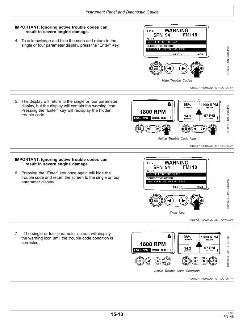
Instrument Panel and Diagnostic Gauge
OURGP11,00000AD 1911OCT064/7
OURGP11,00000AD 1911OCT065/7
OURGP11,00000AD 1911OCT066/7
OURGP11,00000AD 1911OCT067/7
IMPORTANT: Ignoring active trouble codes canresult in severe engine damage.
4. To acknowledge and hide the code and return to thesingle or four parameter display, press the "Enter" Key.
RG13242—UN—30SEP03
Hide Trouble Codes
5. The display will return to the single or four parameterdisplay, but the display will contain the warning icon.Pressing the "Enter" key will redisplay the hiddentrouble code.
RG13176—UN—26SEP03
Active Trouble Code Icon
IMPORTANT: Ignoring active trouble codes canresult in severe engine damage.
6. Pressing the "Enter" key once again will hide thetrouble code and return the screen to the single or fourparameter display.
RG13242—UN—30SEP03
Enter Key
7. The single or four parameter screen will displaythe warning icon until the trouble code condition iscorrected.
RG13243—UN—01OCT03
Active Trouble Code Condition
1510 010311
PN=46
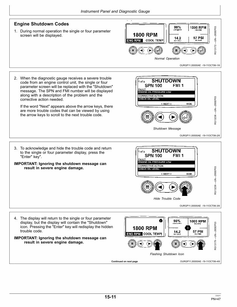
Instrument Panel and Diagnostic Gauge
OURGP11,00000AE 1911OCT061/6
OURGP11,00000AE 1911OCT062/6
OURGP11,00000AE 1911OCT063/6
Continued on next page OURGP11,00000AE 1911OCT064/6
Engine Shutdown Codes1. During normal operation the single or four parameter
screen will be displayed.
RG13172—UN—26SEP03
Normal Operation
2. When the diagnostic gauge receives a severe troublecode from an engine control unit, the single or fourparameter screen will be replaced with the "Shutdown"message. The SPN and FMI number will be displayedalong with a description of the problem and thecorrective action needed.
If the word "Next" appears above the arrow keys, thereare more trouble codes that can be viewed by usingthe arrow keys to scroll to the next trouble code.
RG13238—UN—29SEP03
Shutdown Message
3. To acknowledge and hide the trouble code and returnto the single or four parameter display, press the"Enter" key".
IMPORTANT: Ignoring the shutdown message canresult in severe engine damage.
RG13239—UN—29SEP03
Hide Trouble Code
4. The display will return to the single or four parameterdisplay, but the display will contain the "Shutdown"icon. Pressing the "Enter" key will redisplay the hiddentrouble code.
IMPORTANT: Ignoring the shutdown message canresult in severe engine damage.
RG13179—UN—26SEP03
Flashing Shutdown Icon
1511 010311
PN=47

Instrument Panel and Diagnostic Gauge
OURGP11,00000AE 1911OCT065/6
OURGP11,00000AE 1911OCT066/6
OURGP11,0000237 1923AUG101/6
Continued on next page OURGP11,0000237 1923AUG102/6
5. Pressing the "Enter" key once again will hide thetrouble code and return the screen to the single or fourparameter display.
RG13239—UN—29SEP03
Redisplay Trouble Code
6. The single or four parameter screen will display theshutdown icon until the trouble code condition iscorrected.
IMPORTANT: Ignoring the shutdown message canresult in severe engine damage.
RG13180—UN—26SEP03
Shutdown Icon
Adjusting Backlighting1. Turn the key switch to the ON position. Starting at
the single or four engine parameter display, press the"Menu" key.
RG13159—UN—26SEP03
Menu Key
2. The main menu will be displayed. Use the "Arrow"keys to scroll through the menu until "Adjust Backlight"is highlighted.
RG13181—UN—02OCT03
Select Adjust Backlight
1512 010311
PN=48

Instrument Panel and Diagnostic Gauge
OURGP11,0000237 1923AUG103/6
OURGP11,0000237 1923AUG104/6
Continued on next page OURGP11,0000237 1923AUG105/6
3. Once the "Adjust Backlight" menu item has beenhighlighted, press the "Enter" key to activate the"Adjust Backlight" function.
RG13182—UN—02OCT03
Press Enter Key
4. Use the "Arrow" keys to select the desired backlightintensity.
RG13183—UN—29SEP03
Adjust Backlight Intensity
5. Press the "Menu" key to return to the main menu.
RG19048—UN—23AUG10
Return to Main Menu
1513 010311
PN=49

Instrument Panel and Diagnostic Gauge
OURGP11,0000237 1923AUG106/6
OURGP11,00000AF 1912SEP061/6
OURGP11,00000AF 1912SEP062/6
Continued on next page OURGP11,00000AF 1912SEP063/6
6. Press the "Menu" key to exit the main menu and returnto the engine parameter display.
RG13159—UN—26SEP03
Exit Main Menu
Adjusting Contrast1. Turn the key switch to the ON position. Starting at
the single or four engine parameter display press the"Menu" key.
RG13159—UN—26SEP03
Menu Key
2. The main menu will be displayed. Use the "Arrow"keys to scroll through the menu until "Adjust Contrast"is highlighted.
RG13161—UN—02OCT03
Select Adjust Contrast
3. Once the "Adjust Contrast" menu item has beenhighlighted, press the "Enter" key to activate the"Adjust Contrast" function.
RG13185—UN—02OCT03
Press Enter Key
1514 010311
PN=50

Instrument Panel and Diagnostic Gauge
OURGP11,00000AF 1912SEP064/6
OURGP11,00000AF 1912SEP065/6
OURGP11,00000AF 1912SEP066/6
Continued on next page OURGP11,00000B0 1911OCT061/7
4. Use the "Arrow" keys to select the desired contrastintensity.
RG13186—UN—29SEP03
Adjust Contrast Intensity
5. Press the "Menu" key to return to the main menu.
RG13187—UN—26SEP03
Return To Main Menu
6. Press the "Menu" key to exit the main menu and returnto the engine parameter display.
RG13159—UN—26SEP03
Exit Main Menu
Selecting Units Of Measurement1. Turn the key switch to the ON position. Starting at
the single or four engine parameter display, press the"Menu" key.
RG13159—UN—26SEP03
Menu Key
1515 010311
PN=51
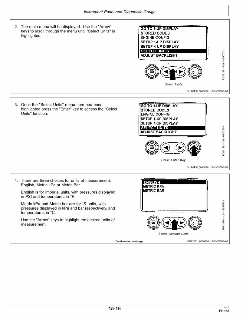
Instrument Panel and Diagnostic Gauge
OURGP11,00000B0 1911OCT062/7
OURGP11,00000B0 1911OCT063/7
Continued on next page OURGP11,00000B0 1911OCT064/7
2. The main menu will be displayed. Use the "Arrow"keys to scroll through the menu until "Select Units" ishighlighted.
RG13188—UN—02OCT03
Select Units
3. Once the "Select Units" menu item has beenhighlighted press the "Enter" key to access the "SelectUnits" function.
RG13189—UN—02OCT03
Press Enter Key
4. There are three choices for units of measurement,English, Metric kPa or Metric Bar.
English is for Imperial units, with pressures displayedin PSI and temperatures in °F.
Metric kPa and Metric bar are for IS units, withpressures displayed in kPa and bar respectively, andtemperatures in °C.
Use the "Arrow" keys to highlight the desired units ofmeasurement.
RG13190—UN—26SEP03
Select Desired Units
1516 010311
PN=52

Instrument Panel and Diagnostic Gauge
OURGP11,00000B0 1911OCT065/7
OURGP11,00000B0 1911OCT066/7
OURGP11,00000B0 1911OCT067/7
Continued on next page OURGP11,00000B1 1911OCT061/18
5. Press the "Enter" key to select the highlighted units.
RG13191—UN—30SEP03
Press Enter Key to Select
6. Press the "Menu" key to return to the main menu.
RG13192—UN—26SEP03
Return To Main Menu
7. Press the "Menu" key to return to the engine parameterdisplay.
RG13159—UN—26SEP03
Press Menu Key
Setup 1Up Display1. Turn the key switch to the ON position. Starting at the
single engine parameter display, press the "Menu" key.
RG13159—UN—26SEP03
Menu Key
1517 010311
PN=53
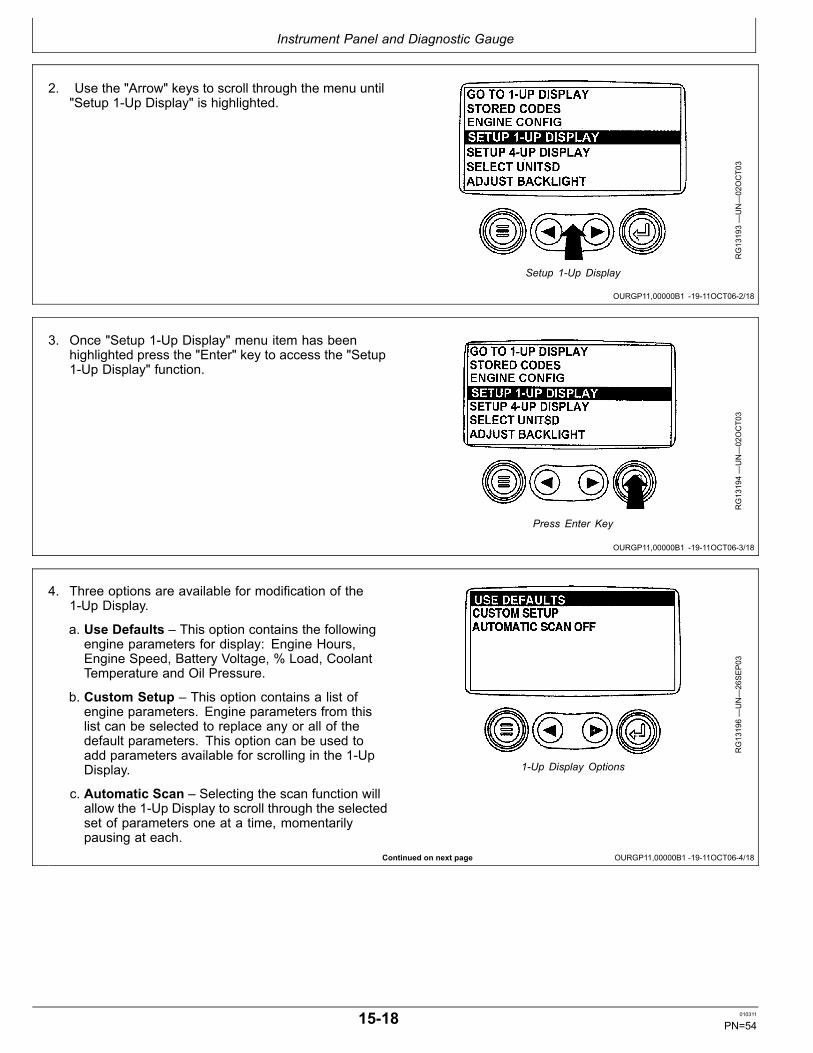
Instrument Panel and Diagnostic Gauge
OURGP11,00000B1 1911OCT062/18
OURGP11,00000B1 1911OCT063/18
Continued on next page OURGP11,00000B1 1911OCT064/18
2. Use the "Arrow" keys to scroll through the menu until"Setup 1Up Display" is highlighted.
RG13193—UN—02OCT03
Setup 1Up Display
3. Once "Setup 1Up Display" menu item has beenhighlighted press the "Enter" key to access the "Setup1Up Display" function.
RG13194—UN—02OCT03
Press Enter Key
4. Three options are available for modification of the1Up Display.
a. Use Defaults – This option contains the followingengine parameters for display: Engine Hours,Engine Speed, Battery Voltage, % Load, CoolantTemperature and Oil Pressure.
b. Custom Setup – This option contains a list ofengine parameters. Engine parameters from thislist can be selected to replace any or all of thedefault parameters. This option can be used toadd parameters available for scrolling in the 1UpDisplay.
c. Automatic Scan – Selecting the scan function willallow the 1Up Display to scroll through the selectedset of parameters one at a time, momentarilypausing at each.
RG13196—UN—26SEP03
1Up Display Options
1518 010311
PN=54
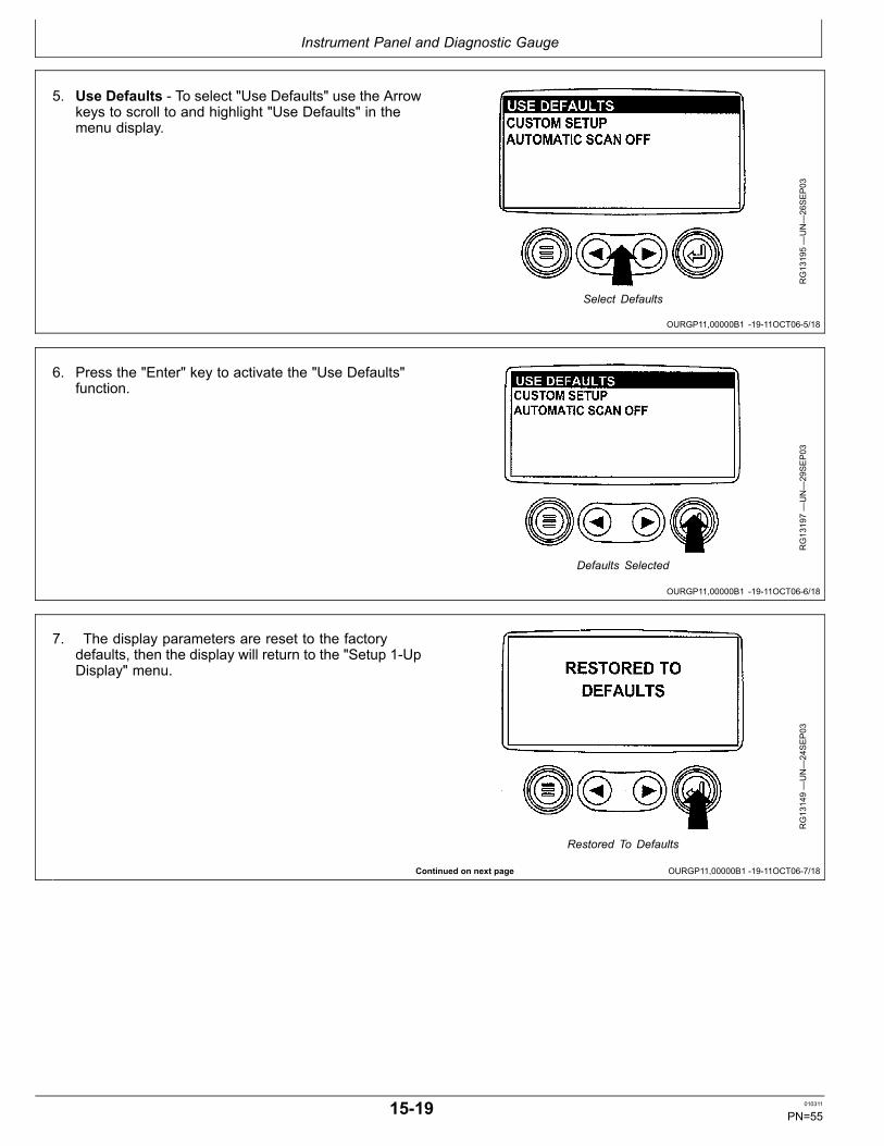
Instrument Panel and Diagnostic Gauge
OURGP11,00000B1 1911OCT065/18
OURGP11,00000B1 1911OCT066/18
Continued on next page OURGP11,00000B1 1911OCT067/18
5. Use Defaults To select "Use Defaults" use the Arrowkeys to scroll to and highlight "Use Defaults" in themenu display.
RG13195—UN—26SEP03
Select Defaults
6. Press the "Enter" key to activate the "Use Defaults"function.
RG13197—UN—29SEP03
Defaults Selected
7. The display parameters are reset to the factorydefaults, then the display will return to the "Setup 1UpDisplay" menu.
RG13149—UN—24SEP03
Restored To Defaults
1519 010311
PN=55

Instrument Panel and Diagnostic Gauge
OURGP11,00000B1 1911OCT068/18
OURGP11,00000B1 1911OCT069/18
Continued on next page OURGP11,00000B1 1911OCT0610/18
8. Custom Setup To perform a custom setup of the1Up Display, use the arrow buttons to scroll to andhighlight "Custom Setup" on the display.
RG13198—UN—26SEP03
Select Custom Setup
9. Press the "Enter" key to display a list of engineparameters.
RG13199—UN—26SEP03
Engine Parameters
10. Use the "Arrow" keys to scroll to and highlight aselected parameter (parameter with a number to rightof it).
RG13150—UN—24SEP03
Select Parameters
1520 010311
PN=56

Instrument Panel and Diagnostic Gauge
OURGP11,00000B1 1911OCT0611/18
OURGP11,00000B1 1911OCT0612/18
Continued on next page OURGP11,00000B1 1911OCT0613/18
11. Press the "Enter" key to deselect the selectedparameter, removing it from the list of parametersbeing displayed on the 1Up Display.
RG13219—UN—26SEP03
Deselect Parameters
12. Use the "Arrow" keys to scroll and highlight the desiredparameter that has not been selected for display(parameter without a number to right of it).
RG13151—UN—24SEP03
Select Desired Parameters
13. Press the "Enter" key to select the parameter forinclusion in the Single Engine Parameter Display.
14. Continue to scroll through and select additionalparameters for the custom 1Up Display. Press the"Menu" key at any time to return to the "Custom Setup"menu.
RG13220—UN—26SEP03
Select Parameters For Display
1521 010311
PN=57

Instrument Panel and Diagnostic Gauge
OURGP11,00000B1 1911OCT0614/18
OURGP11,00000B1 1911OCT0615/18
Continued on next page OURGP11,00000B1 1911OCT0616/18
15.Automatic Scan Selecting the scan function willallow the 1 Up Display to scroll through the selectedset of parameters one at a time. Use the "Arrow" keysto scroll to the "Automatic Scan" function.
RG13221—UN—26SEP03
Automatic Scan Off
16. Press the "Enter" key to toggle the "Automatic Scan"function on.
RG13222—UN—26SEP03
Automatic Scan On
17. Press the "Enter" key again to toggle the "AutomaticScan" function off.
RG13223—UN—26SEP03
Automatic Scan Off
1522 010311
PN=58

Instrument Panel and Diagnostic Gauge
OURGP11,00000B1 1911OCT0617/18
OURGP11,00000B1 1911OCT0618/18
OURGP11,00000B2 1912SEP061/14
Continued on next page OURGP11,00000B2 1912SEP062/14
18. Once the "Use Defaults", "Custom Setup" and"Automatic Scan" functions have been set, press the"Menu" key to return to the main menu.
RG13224—UN—26SEP03
Menu Key
19. Press the "Menu" key to exit the main menu and returnto the engine parameter display.
RG13159—UN—26SEP03
Exit Main Menu
Setup 4Up Display1. Turn the key switch to the ON position. From the
single or four engine parameter display, press the"Menu" key.
RG13159—UN—26SEP03
Menu Key
2. The main menu will be displayed. Use the "Arrow"keys to scroll through the menu until "Setup 4UpDisplay" is highlighted.
RG13225—UN—02OCT03
Select Setup 4Up Display
1523 010311
PN=59

Instrument Panel and Diagnostic Gauge
OURGP11,00000B2 1912SEP063/14
OURGP11,00000B2 1912SEP064/14
Continued on next page OURGP11,00000B2 1912SEP065/14
3. Once the "Setup 4Up Display" menu item has beenhighlighted, press the "Enter" key to activate the"Setup 4Up Display" menu.
RG13226—UN—02OCT03
Press Enter Key
4. Two options are available for the 4Up Display.
a. Use Defaults – This option contains the followingengine parameters for display: Engine Speed,Battery Voltage, Coolant Temperature and OilPressure.
b. Custom Setup – This option contains a list ofengine parameters. Engine parameters from this listcan be selected to replace any or all of the defaultparameters.
RG13244—UN—02OCT03
Select Factory Defaults
5. To reset the display parameters to the factorydefaults, scroll to and highlight "Use Defaults". Pressthe "Enter" key to activate the "Use Defaults" function.A message indicating the display parameters arereset to the factory defaults will be displayed, then thedisplay will return to the "Setup 4Up Display" menu.
RG13149—UN—24SEP03
Restored To Defaults
1524 010311
PN=60
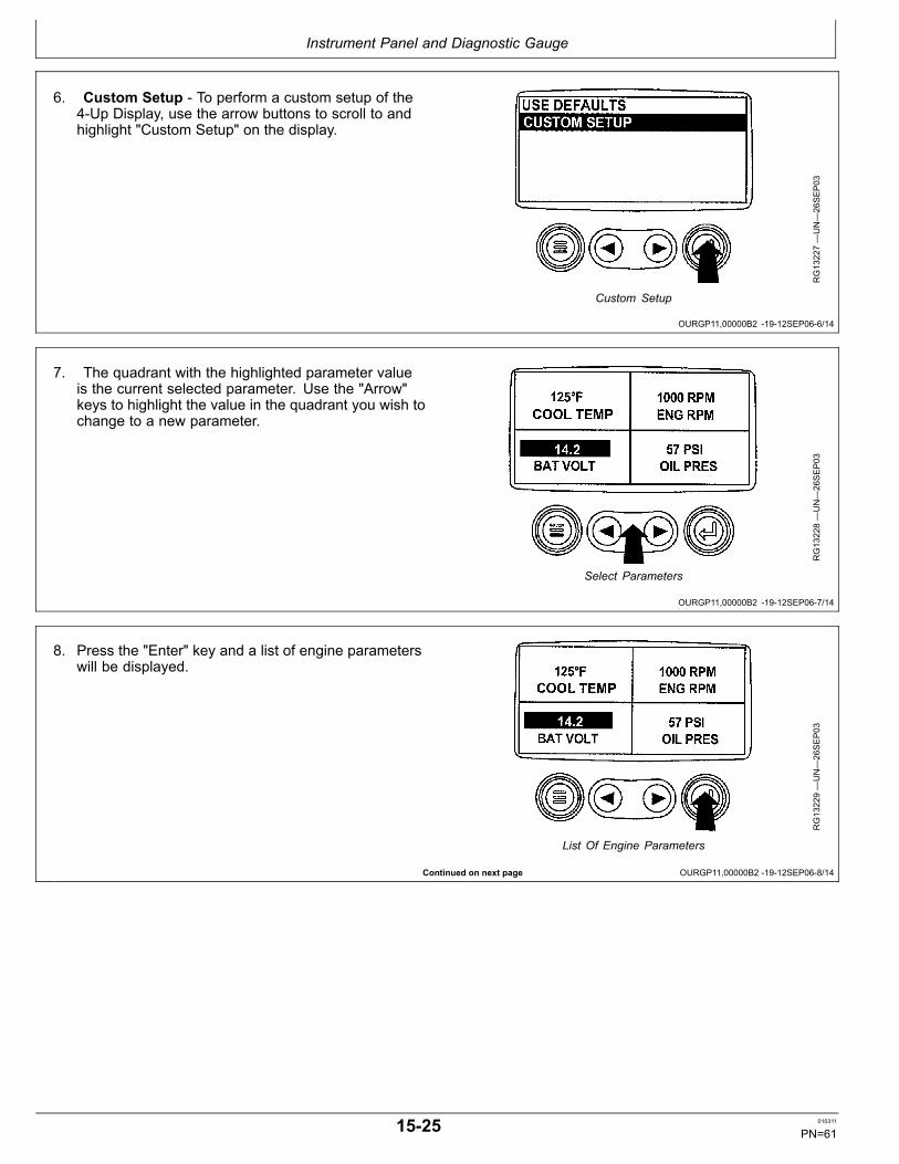
Instrument Panel and Diagnostic Gauge
OURGP11,00000B2 1912SEP066/14
OURGP11,00000B2 1912SEP067/14
Continued on next page OURGP11,00000B2 1912SEP068/14
6. Custom Setup To perform a custom setup of the4Up Display, use the arrow buttons to scroll to andhighlight "Custom Setup" on the display.
RG13227—UN—26SEP03
Custom Setup
7. The quadrant with the highlighted parameter valueis the current selected parameter. Use the "Arrow"keys to highlight the value in the quadrant you wish tochange to a new parameter.
RG13228—UN—26SEP03
Select Parameters
8. Press the "Enter" key and a list of engine parameterswill be displayed.
RG13229—UN—26SEP03
List Of Engine Parameters
1525 010311
PN=61

Instrument Panel and Diagnostic Gauge
OURGP11,00000B2 1912SEP069/14
OURGP11,00000B2 1912SEP0610/14
OURGP11,00000B2 1912SEP0611/14
Continued on next page OURGP11,00000B2 1912SEP0612/14
9. The parameter that is highlighted is the selectedparameter for the screen. Use the "arrow" keys tohighlight the new parameter to be placed in the "4UpDisplay".
RG13230—UN—26SEP03
Select Desired Engine Parameter
10. Press the "Enter" key to change the selectedparameter in the quadrant to the new parameter.
RG13231—UN—26SEP03
Enter Selected Parameter
11. Use the "Menu" keys to return to the "4Up CustomSetup" screen.
RG13232—UN—26SEP03
Return To 4Up Custom Setup
12. The selected quadrant has now changed to the newselected parameter.
RG13153—UN—24SEP03
4Up Display
1526 010311
PN=62
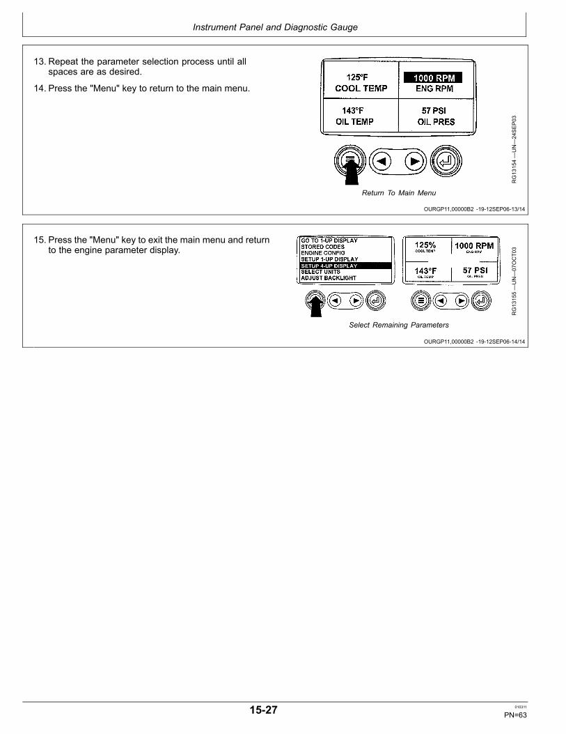
Instrument Panel and Diagnostic Gauge
OURGP11,00000B2 1912SEP0613/14
OURGP11,00000B2 1912SEP0614/14
13. Repeat the parameter selection process until allspaces are as desired.
14. Press the "Menu" key to return to the main menu.
RG13154—UN—24SEP03
Return To Main Menu
15. Press the "Menu" key to exit the main menu and returnto the engine parameter display.
RG13155—UN—07OCT03
Select Remaining Parameters
1527 010311
PN=63

Engine Operation
Continued on next page OURGP11,0000070 1919SEP061/3
Engine BreakIn Service
RG9924
—UN—17NOV99
Check Engine Oil
RG8707A—UN—03SEP99
Crosshatch Pattern on Dipstick
A—Crosshatch Pattern
The engine is ready for normal operation. However, extracare during the first 100 hours of operation will result inmore satisfactory longterm engine performance and life.DO NOT exceed 100 hours of operation with breakin oil.
1. This engine is factoryfilled with John Deere DIESELENGINE BREAKIN OIL (SAE 10W30). Operate theengine at heavy loads with minimal idling during thebreakin period.
2. If the engine has significant operating time atidle, constant speeds, and/or light load usage, ormakeup oil is required in the first 100 hour period,a longer breakin period may be required. In thesesituations, an additional 100 hour breakin period isrecommended using a new change of John DeereDIESEL ENGINE BREAKIN OIL and a new JohnDeere oil filter.
IMPORTANT: DO NOT add makeup oil until the oillevel is BELOW the ADD mark on dipstick.John Deere ENGINE BREAKIN OIL (TY22041)should be used to make up any oil consumedduring the breakin period.
3. Check engine oil level more frequently during enginebreakin period. If oil must be added during this
period, John Deere DIESEL ENGINE BREAKIN OILis preferred. See DIESEL ENGINE BREAKIN OIL, inFuels, Lubricants, and Coolant Section for other oilsallowed.
IMPORTANT: Do not use PLUS50 oil or engine oilsmeeting any of the following during the first 100hours of operation of a new or rebuilt engine:
API CJ4 API CFAPI CI4 PLUS ACEA E7API CI4 ACEA E6API CH4 ACEA E5API CG4 ACEA E4API CF4 ACEA E3API CF2
These oils will not allow the engine tobreakin properly.
DO NOT fill above the crosshatch pattern (A) orthe FULL mark, whichever is present. Oil levelsanywhere within the crosshatch are consideredin the acceptable operating range.
201 010311
PN=64

Engine Operation
OURGP11,0000070 1919SEP062/3
OURGP11,0000070 1919SEP063/3
4. During the first 20 hours, avoid prolonged periods ofengine idling or sustained maximum load operation. Ifengine will idle longer than 5 minutes, stop engine. Atlow idle, engine should have an oil pressure of at least138 kPa (1.38 bar) (20 psi).
5. Before the first 100 hours (maximum), change engineoil and replace engine oil filter (A). (See CHANGINGENGINE OIL AND REPLACING FILTER in Lubricationand Maintenance/500 Hour/12 Month Section.) Fillcrankcase with the normal seasonal viscosity gradeoil. (See DIESEL ENGINE OIL, in Fuels, Lubricants,and Coolant Section.)
NOTE: Some increase in oil consumption may beexpected when low viscosity oils are used.Check oil levels more frequently.
If temperature is below 0°C (32°F), it may benecessary to use cold weather starting aids (SeeCOLDWEATHEROPERATION, later in this section).
If air temperature is below 25°C (13°F),use an engine block heater.
RG8709A—UN—03SEP99
Replace Engine Oil Filter
A—Oil Filter
6. Watch coolant temperature gauge (A) closely. Ifcoolant temperature rises above 100°C (212°F),reduce load on engine. Unless temperature dropsquickly, stop the engine and determine the causebefore resuming operation.
NOTE: When the coolant temperature gauge readsapproximately 112°C (234°F), the enginewill shutdown automatically, if equippedwith safety controls.
7. Watch oil pressure gauge (B) for pressure withinspecification.
SpecificationEngine OilPressure1—Full LoadRated Speed...........................310±103 kPa (3.10±1.03 bar) (45±15 psi)Engine OilPressure—Low Idle..................... 138 kPa (1.38 bar) (20 psi) (minimum)Engine CoolantTemperatureRange—Temperature...................................... 82°—92°C (180°—197°F)
8. Check polyvee belt for proper alignment and seatingin pulley grooves.
RG13720—UN—11NOV04
Watch Coolant Temperature and Oil Pressure on Panel
A—Engine CoolantTemperature Gauge
B—Oil Pressure Gauge
1 At normal operating sump temperature of 115°C (240°F)and at speeds of 1500—2100 rpm).
202 010311
PN=65
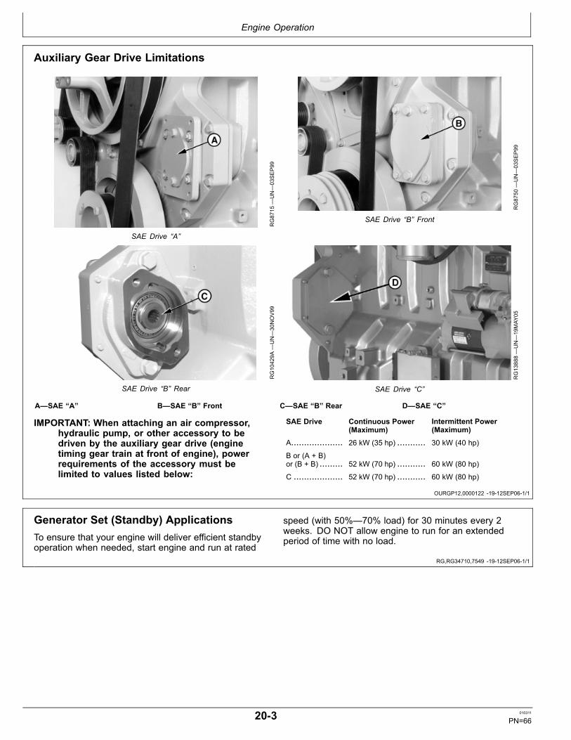
Engine Operation
OURGP12,0000122 1912SEP061/1
RG,RG34710,7549 1912SEP061/1
Auxiliary Gear Drive Limitations
RG8715
—UN—03SEP99
SAE Drive “A”
RG8750
—UN—03SEP99
SAE Drive “B” Front
RG10429A
—UN—30NOV99
SAE Drive “B” Rear
RG13888—UN—19MAY
05
SAE Drive “C”
A—SAE “A” B—SAE “B” Front C—SAE “B” Rear D—SAE “C”
IMPORTANT: When attaching an air compressor,hydraulic pump, or other accessory to bedriven by the auxiliary gear drive (enginetiming gear train at front of engine), powerrequirements of the accessory must belimited to values listed below:
SAE Drive Continuous Power(Maximum)
Intermittent Power(Maximum)
A.................... 26 kW (35 hp) ........... 30 kW (40 hp)
B or (A + B)or (B + B) ......... 52 kW (70 hp) ........... 60 kW (80 hp)
C ................... 52 kW (70 hp) ........... 60 kW (80 hp)
Generator Set (Standby) ApplicationsTo ensure that your engine will deliver efficient standbyoperation when needed, start engine and run at rated
speed (with 50%—70% load) for 30 minutes every 2weeks. DO NOT allow engine to run for an extendedperiod of time with no load.
203 010311
PN=66

Engine Operation
OMRGP15,0000122 1912SEP061/3
Continued on next page OMRGP15,0000122 1912SEP062/3
Starting the EngineThe following instructions apply to the optional controlsand instruments available through the John Deere PartsDistribution Network. The controls and instruments foryour engine may be different from those shown here;always follow manufacturer’s instructions.
CAUTION: Before starting engine in a confinedbuilding, install proper outlet exhaust ventilationequipment. Always use safety approvedfuel storage and piping.
NOTE: If temperature is below 0°C (32°F), it may benecessary to use cold weather starting aids. (SeeCOLD WEATHER OPERATION in this group.)
1. Perform all prestarting checks outlined in Lubricationand Maintenance/Daily section later in this manual.
TS220—UN—23AUG88
Use Proper Ventilation
2. Open the fuel supply shutoff valve, if equipped.
3. Disengage power to any engine drivelines.
4. Set slow idle as follows:
Panels with highlow speed select rocker switch(B) only: Set slow speed by pressing lower half ofswitch.
Panels with optional analog throttle(s) (A) : Sethighlow speed select rocker switch to slow (turtle),then push in on analog throttle handle or turn fullcounterclockwise to set analog throttle(s) to slowspeed.
IMPORTANT: Do not operate the starter for morethan 30 seconds at a time. To do so mayoverheat the starter. If the engine does not startthe first time, wait at least 2 minutes beforetrying again. If engine does not start after fourattempts, see Troubleshooting section.
A—Analog Throttle Control(Optional)
B—Speed Select RockerSwitch
RG13722—UN—11NOV04
Analog Throttle Control and Speed Select Switch
204 010311
PN=67

Engine Operation
OMRGP15,0000122 1912SEP063/3
OURGP11,000004E 1912SEP061/1
5. All Engines Turn the key switch to the ON position.The "Wait To Start Preheating" message will bedisplayed when ambient temperatures requirepreheating (for engines with preheating options). Thetimer will display minutes and seconds, counting downto zero. Once the timer has reach 0:00 and the "Waitto Start" message is no longer displayed, you maystart the engine.
Turn the key start switch (A) clockwise to crank theengine. When the engine starts, release the keyswitch so that it returns to the “ON” position.
IMPORTANT: If the key switch is released beforethe engine starts, wait until the starterand the engine stop turning before tryingagain. This will prevent possible damageto the starter and/or flywheel.
6. After engine starts, idle engine at not more than 1200rpm until warm. (See WARMING ENGINE later in thissection).
Panels with highlow speed select rocker switch(B) only: Set rpm using bump speed enable switch(C) with speed select rocker switch (D).
Panels with optional analog throttle (E): Set eitherhighlow speed select switch (B) or analog throttle (E)to slow speed, and set desired speed with remainingcontrol.
NOTE: Engine control unit (ECU) reads the higherof the highlow speed select rocker switch orthe analog throttle speed settings.
RG13723—UN—11NOV04
Start And Idle On Panel
A—Key Start SwitchB—HighLow Speed Select
Rocker SwitchC—BumpSpeed Enable Rocker
Switch
D—Speed Select RockerSwitch
E—Analog Throttle Control(Optional)
7. Check all gauges for normal engine operation.If operation is not normal, stop the engine anddetermine the cause. (For normal gauge pressuresand temperatures, see BREAKIN SERVICE earlierin this section.)
Restarting Engine Which Has Run Out OfFuelFill the fuel tank and then bleed the fuel system beforerestarting engine (refer to Service as Required section,BLEEDING FUEL SYSTEM).
205 010311
PN=68

Engine Operation
OMRGP15,0000124 1912SEP061/1
OURGP11,000004F 1919SEP061/1
Warming EngineIMPORTANT: To ensure proper lubrication, operate
engine at or below 1200 rpm with no load for1—2 minutes. Extend this period 2—4 minuteswhen operating at temperatures below freezing.
Engines used in generator set applicationswhere the ECU is programmed to lock engineat a specified speed, may not have a slow idlefunction. Operate these engines at high idlefor 1 to 2 minutes before applying the load.This procedure does not apply to standbygenerator sets where the engine is loadedimmediately upon reaching rated speed.
1. Check oil pressure gauge (A) as soon as engine starts.If gauge needle does not rise to minimum oil pressureof 138 kPa (1.38 bar) (20 psi) within 5 seconds, stopthe engine and determine the cause. Normal engineoil pressure is 310 ± 103 kPa (3.10 ± 1.03 bar) (45 ±15 psi) at rated fullload speed (1500—2100 rpm) withoil at normal operating temperature of 115°C (240°F).
2. Watch coolant temperature gauge (B). Do not placeengine under full load until it is properly warmed up.The normal engine coolant temperature range is82°—92°C (180°—197°F).
RG13724—UN—11NOV04
Oil Pressure and Coolant Temperature Gauges On Panel
A—Engine Oil Pressure Gauge B—Engine CoolantTemperature Gauge
NOTE: It is a good practice to operate the engine undera lighter load and at lower speeds than normalfor the first few minutes after startup.
Normal Engine Operation
Observe engine coolant temperature and engineoil pressure. Temperatures and pressures will varybetween engines and with changing operating conditions,temperatures, and loads.
Normal engine coolant operating temperature range is82°—92°C (180°—197°F). If coolant temperature risesabove 100°C (212°F), reduce load on engine. Unlesstemperature drops quickly, stop engine and determinecause before resuming operation.
Normal engine oil pressure at slow idle should be at least138 kPa (20 psi) and should rise to 310 kPa (45 psi) atrated speed.
Operate the engine under a lighter load and at slowerthan normal speed for first 15 minutes after startup. DONOT run engine at slow idle.
IMPORTANT: Should the engine die while operatingunder load, immediately remove load and restartthe engine. Overheating of the turbochargerparts may occur when oil flow is stopped.
Stop engine immediately if there are any signs of partfailure. Symptoms that may be early signs of engineproblems are:
• Sudden drop in oil pressure• Abnormal coolant temperatures• Unusual noise or vibration• Sudden loss of power• Excessive black exhaust• Excessive fuel consumption• Excessive oil consumption• Fluid leaks
NOTE: These engines meet emission standards with anexhaust gas recirculation system and a variablegeometry turbocharger. A revving sound may beheard for an instant after starting, as the variablegeometry turbocharger recycles. This is normal.
206 010311
PN=69

Engine Operation
OURGP11,0000051 1916DEC101/1
Cold Weather Operation
CAUTION: Ether injector starting fluid is highlyflammable. DO NOT use starting fluid on enginesequipped with air intake heaters.
DO NOT use starting fluid near fire, sparks,or flames. DO NOT incinerate or puncturea starting fluid container.
IMPORTANT: Engines with Rear PTO Turn offor unload all pumps, auxiliary drives, andcompressors before cold weather startingto reduce drag on engine.
Engines may be equipped with coolant heaters or etherinjectors as cold weather starting aids.
Starting aids are required below 0°C (32°F). They willenhance starting performance above these temperaturesand may be needed to start applications that have highparasitic loads during cranking and/or start accelerationto idle.
Using correct grade of oil (per engine and machineoperator’s manual) is critical to achieving adequate coldweather cranking speed. Synthetic oils have improvedflow at low temperatures.
Other cold weather starting aids are required attemperatures below 25°C (13°F) or at altitudes above1500 m (5000 ft).
1. Follow steps 1—4 as listed under STARTING THEENGINE, earlier in this section, then proceed asfollows according to the instrument (gauge) panel onyour engine.
2. Use cold weather starting aids as needed. Followsupplier instructions for starting aid provided on yourengine. A booster battery can be connected if needed(see USING A BOOSTER BATTERY OR CHARGER,later in this section).
3. Follow remaining steps 5—7 as listed earlier in“Starting Engine” section.
Additional information on cold weather operation isavailable from your authorized servicing dealer.
TS1356
—UN—18MAR92
Handle Starting Fluid with Care
RG19813—UN—15DEC10
Cold Weather Starting Guidelines
A—Minimum Cranking RPMB—No AidsC—Electric Air HeatD—Block Heat
E—EtherF—Electric Air Heat and Block
HeatG—Ether and Block Heat
207 010311
PN=70

Engine Operation
Continued on next page OMRGP15,0000126 1912SEP061/3
Changing Engine SpeedNOTE: On engines with 2position throttles, speeds
are not adjustable. These throttles allowsoperation only at the preset rated speed or atidle using the single switch (A).
Changing from slow to fast speed using StandardHighLow Speed Select Rocker Switch (A) (IfEquipped):
• For slow speed, press lower half of switch (indicatedby turtle symbol).• For fast speed, press upper half of switch (indicated byrabbit symbol).
NOTE: To adjust preset fast or slow speeds for HighLowSpeed Select Rocker Switch:
1. Select fast (rabbit) or slow (turtle) position onHighLow Speed Select Rocker Switch (A).
2. Press and hold top or bottom half of BumpSpeed Enable Rocker Switch (B) while usingSpeed Select Rocker Switch (C).
3. Use Speed Select Rocker Switch (C) to bumpengine speed up (+) or down ().
NOTE: Once the speed has been set, the Bump SpeedEnable Switch (B) must be pressed and releasedthree times within two seconds to commit thenew slow or fast speed to memory. If not done,the engine’s new slow or fast speed will only beeffective until the key switch is shut off. Then thespeed will revert to its previous setting.
Changing from slow to fast speed using AdjustableHighLow Speed Select Rocker Switch (A) (IfEquipped):
Instrument panels have an adjustable threepositionrocker switch (A) that can be used to select slow idle, fastidle, or an adjustable (“ADJ”) intermediate speed.
• For slow speed, press lower half of rocker switch(indicated by turtle symbol).• For fast speed, press upper half of rocker switch(indicated by rabbit symbol).
NOTE: To adjust preset fast or slow speeds withadjustable HighLow Speed Select Rocker Switch:
RG13725—UN—11NOV04
Changing Engine Speed with FullFeatured Panel
A—HighLow Speed SelectRocker Switch
B—BumpSpeed Enable RockerSwitch
C—Speed Select RockerSwitch
D—Analog Throttle Control(Optional)
1. Select middle position (ADJ) or slow (turtle)position on the optional Adjustable ThreeStateSpeed Select Rocker Switch (A).
2. Press and hold top or bottom half of BumpSpeed Enable Rocker Switch (B) while usingSpeed Select Rocker Switch (C).
3. Use Speed Select Rocker Switch (C) to bumpengine speed up (+) or down ().
NOTE: Slow (turtle) position is factory preset at lowengine idle, while middle (ADJ) position isfactory set at high engine idle.
NOTE: Once the speed has been set, the Bump SpeedEnable Switch (B) must be pressed and releasedthree times within two seconds to commit thenew slow or fast speed to memory. If not done,the engine’s new slow or fast speed will onlybe effective until the key is shut off. Then thespeed will revert to its previous setting.
208 010311
PN=71

Engine Operation
OMRGP15,0000126 1912SEP062/3
OMRGP15,0000126 1912SEP063/3
RG,RG34710,7554 1912SEP061/1
Changing engine speed using optional analogthrottle control (D)
NOTE: Pushing in on analog throttle will immediatelytake engine to slow idle speed.
1. Set HighLow Speed Select Rocker Switch (A) to lowspeed position.
2. Turn analog throttle clockwise to increase speed orcounterclockwise to decrease speed.
NOTE: Engine Control Unit (ECU) reads the higher ofthe HighLow Speed Select Rocker Switch or theAnalog Throttle(s) Speed Settings. With HighLowswitch at low speed, Analog Throttle(s) will controlspeed higher than low idle setting.
A—HighLow Speed SelectRocker Switch
B—BumpSpeed Enable RockerSwitch
C—Speed Select RockerSwitch
D—Analog Throttle Control(Optional)
RG13725—UN—11NOV04
Changing Engine Speed with FullFeatured Panel
Changing engine speeds on engines equippedwith the Basic Instrument Panel
The basic instrument panel has a “ramp” throttle switch (E)with a spring loaded return to the center rest position (Off).
To increase the engine speed, press and hold upperhalf of rocker switch (E) (indicated by rabbit symbol) toincrease or ramp up the engine speed to desired speed.Release the rocker switch.
Press lower half of rocker switch (indicated by turtlesymbol) to decrease or ramp down the engine speed todesired speed. Release the rocker switch.
The settings will not be stored.
RG13289—UN—30OCT03
Changing Engine Speed With Basic Panel
E—HighLow Speed SelectRocker Switch
Avoid Excessive Engine Idling
Prolonged idling may cause the engine coolanttemperature to fall below its normal range. This, in turn,causes crankcase oil dilution, due to incomplete fuelcombustion, and permits formation of gummy deposits onvalves, pistons, and piston rings. It also promotes rapidaccumulation of engine sludge and unburned fuel in theexhaust system.
Once an engine is warmed to normal operatingtemperatures, engine should be idled at slow idle speed.
Slow idle speed for this engine is 850 rpm at factory. If anengine will be idling for more than 5 minutes, stop andrestart later.
NOTE: Generator set applications where the ECUis locked at a specified speed may not have aslow idle function. These engines will idle atnoload governed speed (high idle).
209 010311
PN=72

Engine Operation
OMRGP15,0000127 1912SEP061/1
Stopping the Engine1. Pull PTO clutch lever rearward (away from engine) to
disengage clutch, if equipped.
IMPORTANT: Before stopping an engine thathas been operating at working load, idleengine at least 2 minutes at 1000—1200rpm to cool hot engine parts.
Engines in generator set applications wherethe ECU is locked at a specified speed and noslow idle function is available, run engine forat least 2 minutes at fast idle and no load.
2. Run engine at 1000—1200 rpm for at least 2 minutesto cool.
Panels with highlow speed select rocker switch(B) only: Set rpm using bump speed enable switch(C) with speed select rocker switch (D).
Panels with optional analog throttle (E): Set eitherhighlow speed select switch (B) or analog throttlecontrol (E) to slow idle, and set desired speed withremaining control.
NOTE: Engine control unit (ECU) reads the higherof the highlow speed select rocker switch orthe analog throttle speed settings.
3. Push in on analog throttle control handle (if equipped)so that engine goes to slow idle, or set slow speedwith highlow speed select rocker switch.
4. Turn key start switch (A) to “OFF” position to stop theengine. Remove ignition key.
IMPORTANT: Make sure that exhaust stack rain cap(F) is installed when engine is not running. Thiswill prevent water and dirt from entering engine.
RG13723—UN—11NOV04
Stopping the Engine (FullFeatured Panel Shown)
RG9933
—UN—18NOV99
Exhaust Stack Rain Cap
A—Key Start SwitchB—HighLow Speed Select
Rocker SwitchC—BumpSpeed Enable Rocker
Switch
D—Speed Select RockerSwitch
E—Analog Throttle Control(Optional)
F—Exhaust Stack Rain Cap
2010 010311
PN=73

Engine Operation
RG,RG34710,7556 1912SEP061/1
Using a Booster Battery or ChargerA 12volt booster battery can be connected in parallel withbattery(ies) on the unit to aid in cold weather starting.ALWAYS use heavyduty jumper cables.
CAUTION: Gas given off by battery is explosive.Keep sparks and flames away from battery.Before connecting or disconnecting a batterycharger, turn charger off. Make last connectionand first disconnection at a point away frombattery. Always connect NEGATIVE (—) cablelast and disconnect this cable first.
IMPORTANT: Be sure polarity is correct before makingconnections. Reversed polarity will damageelectrical system. Always connect positive topositive and negative to ground. Always use12volt booster battery for 12volt electricalsystems and 24volt booster battery(ies)for 24volt electrical systems.
WARNING: Battery posts, terminals, and relatedaccessories contain lead and lead compounds, chemicalsknown to the State of California to cause cancer andreproductive harm. Wash hands after handling.
1. Connect booster battery or batteries to produce therequired system voltage for your engine application.
NOTE: To avoid sparks, DO NOT allow the free endsof jumper cables to touch the engine.
2. Connect one end of jumper cable to the POSITIVE (+)post of the booster battery.
3. Connect the other end of the jumper cable to thePOSITIVE (+) post of battery connected to starter.
4. Connect one end of the other jumper cable to theNEGATIVE (—) post of the booster battery.
5. ALWAYS complete the hookup by making the lastconnection of the NEGATIVE (—) cable to a goodground on the engine frame and away from thebattery(ies).
6. Start the engine. Disconnect jumper cablesimmediately after engine starts. DisconnectNEGATIVE (—) cable first.
TS204—UN—23AUG88
Exploding Battery
RG4678
—UN—14DEC88
12Volt System
RG4698
—UN—14DEC88
24Volt System
A—12Volt MachineBattery(ies)
B—12Volt Booster Battery(ies)
C—Booster CableD—Cable to Starter Motor
2011 010311
PN=74

Lubrication and Maintenance
OURGP12,0000136 1911OCT061/1
RG,RG34710,7558 1912SEP061/1
Observe Service IntervalsUsing hour meter (A) on diagnostic gauge as a guide,perform all services at the hourly intervals indicated onfollowing pages. At each scheduled maintenance interval,perform all previous maintenance operations in addition tothe ones specified. Keep a record of hourly intervals andservices performed, using charts provided in Lubricationand Maintenance Records section.
IMPORTANT: Recommended service intervals arefor normal operating conditions. Performmaintenance at interval which occurs first,for example, either at 500 hours of operationOR every 12 months. Service MORE OFTEN ifengine is operated under adverse conditions.Neglecting maintenance can result in failuresor permanent damage to the engine.
A—Hour Meter
RG13728—UN—11NOV04
Hour Meter On Panel
Use Correct Fuels, Lubricants, and CoolantIMPORTANT: Use only fuels, lubricants, and
coolants meeting specifications outlined inFuels, Lubricants, and Coolant section whenservicing your John Deere Engine.
Consult your John Deere engine distributor, servicingdealer or your nearest John Deere Parts Network forrecommended fuels, lubricants, and coolant. Alsoavailable are necessary additives for use when operatingengines in tropical, arctic, or any other adverse conditions.
TS100—UN—23AUG88
John Deere Parts Network
251 010311
PN=75
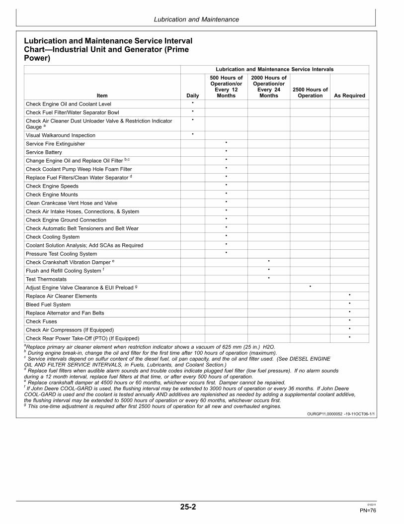
Lubrication and Maintenance
OURGP11,0000052 1911OCT061/1
Lubrication and Maintenance Service IntervalChart—Industrial Unit and Generator (PrimePower)
Lubrication and Maintenance Service Intervals
Item Daily
500 Hours ofOperation/orEvery 12Months
2000 Hours ofOperation/orEvery 24Months
2500 Hours ofOperation As Required
Check Engine Oil and Coolant Level •
Check Fuel Filter/Water Separator Bowl •
Check Air Cleaner Dust Unloader Valve & Restriction IndicatorGauge a
•
Visual Walkaround Inspection •
Service Fire Extinguisher •
Service Battery •
Change Engine Oil and Replace Oil Filter b,c •
Check Coolant Pump Weep Hole Foam Filter •
Replace Fuel Filters/Clean Water Separator d •
Check Engine Speeds •
Check Engine Mounts •
Clean Crankcase Vent Hose and Valve •
Check Air Intake Hoses, Connections, & System •
Check Engine Ground Connection •
Check Automatic Belt Tensioners and Belt Wear •
Check Cooling System •
Coolant Solution Analysis; Add SCAs as Required •
Pressure Test Cooling System •
Check Crankshaft Vibration Damper e •
Flush and Refill Cooling System f •
Test Thermostats •
Adjust Engine Valve Clearance & EUI Preload g •
Replace Air Cleaner Elements •
Bleed Fuel System •
Replace Alternator and Fan Belts •
Check Fuses •
Check Air Compressors (If Equipped) •
Check Rear Power TakeOff (PTO) (If Equipped) •aReplace primary air cleaner element when restriction indicator shows a vacuum of 625 mm (25 in.) H2O.b During engine breakin, change the oil and filter for the first time after 100 hours of operation (maximum).c Service intervals depend on sulfur content of the diesel fuel, oil pan capacity, and the oil and filter used. (See DIESEL ENGINEOIL AND FILTER SERVICE INTERVALS, in Fuels, Lubricants, and Coolant Section.)d Replace fuel filters when audible alarm sounds and trouble codes indicate plugged fuel filter (low fuel pressure). If no alarm soundsduring a 12 month interval, replace fuel filters at that time, or after every 500 hours of operation.e Replace crankshaft damper at 4500 hours or 60 months, whichever occurs first. Damper cannot be repaired.f If John Deere COOLGARD is used, the flushing interval may be extended to 3000 hours of operation or every 36 months. If John DeereCOOLGARD is used and the coolant is tested annually AND additives are replenished as needed by adding a supplemental coolant additive,the flushing interval may be extended to 5000 hours of operation or every 60 months, whichever occurs first.g This onetime adjustment is required after first 2500 hours of operation for all new and overhauled engines.
252 010311
PN=76

Lubrication and Maintenance
OURGP11,0000053 1911OCT061/1
Lubrication and Maintenance Service IntervalChart—Generator (Standby) ApplicationsNOTE: The service intervals in the Lubrication and
Maintenance sections that follow reflect standard
engines. Use service intervals listed belowfor generator (standby) applications. Matchservice items below to titles in Lubrication andMaintenance sections for procedures.
Lubrication and Maintenance Service Intervals
ItemEvery 2Weeks
500 Hours ofOperation/orEvery 12Months
2000 Hours ofOperation/orEvery 24Months
2500 Hoursof Operation As Required
Operate Engine at Rated Speed and 50%—70% Load aMinimum of 30 Minutes
•
Check Engine Oil and Coolant Level •
Check Fuel Filter/Water Separator Bowl •
Check Air Cleaner Dust Unloader Valve & Restriction IndicatorGauge a
•
Visual Walkaround Inspection •
Service Fire Extinguisher •
Service Battery •
Change Engine Oil and Replace Oil Filter b,c •
Check Coolant Pump Weep Hole Foam Filter •
Check Engine Mounts •
Replace Fuel Filters/Clean Water Separator d •
Check Engine Ground Connection •
Clean Crankcase Vent Hose and Valve •
Check Air Intake Hoses, Connections, & System •
Check Engine Ground Connection •
Check Automatic Belt Tensioners and Belt Wear •
Check Cooling System •
Coolant Solution Analysis; Add SCAs as Required •
Pressure Test Cooling System •
Check Crankshaft Vibration Damper e •
Flush and Refill Cooling System f •
Test Thermostats •
Adjust Engine Valve Clearance and EUI Preload g •
Replace Air Cleaner Elements •
Bleed Fuel System •
Replace Alternator and Fan Belts •
Check Fuses •
Check Air Compressors (If Equipped) •
Check Rear Power TakeOff (PTO) (If Equipped) •aReplace primary air cleaner element when restriction indicator shows a vacuum of 625 mm (25 in.) H2O.b During engine breakin, change the oil and filter for the first time after 100 hours of operation (maximum).c Service intervals depend on sulfur content of the diesel fuel, oil pan capacity, and the oil and filter used. (See DIESEL ENGINEOIL AND FILTER SERVICE INTERVALS, in Fuels, Lubricants, and Coolant Section.)d Replace fuel filters when audible alarm sounds and trouble codes indicate plugged fuel filter (low fuel pressure). If no alarm soundsduring a 12 month interval, replace fuel filters at that time, or after every 500 hours of operation.e Replace crankshaft damper at 4500 hours or 60 months, whichever occurs first. Damper cannot be repaired.f If John Deere COOLGARD is used, the flushing interval may be extended to 3000 hours of operation or every 36 months. If John DeereCOOLGARD is used and the coolant is tested annually AND additives are replenished as needed by adding a supplemental coolant additive,the flushing interval may be extended to 5000 hours of operation or every 60 months, whichever occurs first.g This onetime adjustment is required after first 2500 hours of operation for all new and overhauled engines.
253 010311
PN=77

Lubrication and Maintenance/Daily
Continued on next page RG,RG34710,7561 1912SEP061/4
Daily Prestarting ChecksDo the following BEFORE STARTING THE ENGINE forthe first time each day:
IMPORTANT: DO NOT add makeup oil until the oillevel is BELOW the ADD mark.
1. Check engine oil level on dipstick. Add as required,using seasonal viscosity grade oil. (See DIESELENGINE OIL in Fuels, Lubricants, and Coolant sectionfor oil specifications.)
Oil may be added at timing gear cover filler cap (A) oroil pan filler adapter ports (B), if equipped.
IMPORTANT: DO NOT fill above the top of crosshatcharea (C) on the dipstick. Oil levels anywherewithin crosshatch are considered in theacceptable operating range.
A—Timing Cover Filler CapB—Oil Pan Filler Adapter Port
C—Crosshatch Area ofDipstick
RG9924
—UN—17NOV99
Check Engine Oil
RG8724
—UN—03SEP99
Timing Gear Cover Filler Cap
RG8751
—UN—03SEP99
Oil Pan Filler Adapter Ports
RG8707B—UN—03SEP99
Do Not Fill Above Top Mark
301 010311
PN=78

Lubrication and Maintenance/Daily
Continued on next page RG,RG34710,7561 1912SEP062/4
CAUTION: Explosive release of fluidsfrom pressurized cooling system cancause serious burns.
Only remove filler cap when engine is cold orwhen cool enough to touch with bare hands.Slowly loosen cap to first stop to relievepressure before removing completely.
2. Check the coolant level when engine is cold. Coolantlevel should be at bottom of filler neck. Fill radiator(A) with proper coolant solution if level is low.(See ADDING COOLANT in Service as Requiredsection.) Check overall cooling system for leaks.
Refer to your vehicle’s operator’s manual forrecommendations for nonJohn Deere suppliedaccessories.
A—Radiator
TS281—UN—23AUG88
HighPressure Fluids
RG8735A—UN—03SEP99
Fill Radiator
302 010311
PN=79

Lubrication and Maintenance/Daily
RG,RG34710,7561 1912SEP063/4
RG,RG34710,7561 1912SEP064/4
3. If the air cleaner has an automatic dust unloadervalve (A), squeeze the unloader valve on air cleanerassembly to clear away any dust buildup.
IMPORTANT: Do not exceed maximum air intakerestriction. A clogged air cleaner elementwill cause excessive intake restriction and areduced air supply to the engine.
If equipped with air intake restriction indicator gauge(B), check gauge and service air cleaner if air intakerestriction exceeds specifications.
SpecificationMaximum Air IntakeRestriction—Vacuum.......................................................25 in. (625 mm)
H2O (6.25 kPa) (0.06 bar) (1.0 psi)
A—Dust Unloader Valve B—Restriction Indicator Gauge
RG8717A—UN—12JU
L99
Automatic Dust Unloader Valve
RG8719A—UN—12JU
L99
Air Intake Restriction Indicator Gauge
NOTE: Amber warning indicator on instrument paneldiagnostic gauge will flash if amount of water infuel filter sediment bowl is excessive.
4. Loosen thumb screw (C) and drain water and debrisfrom bowl into a suitable container, as needed.
Dispose of water and debris in an environmentallysafe manner.
5. Make a thorough inspection of the enginecompartment. Look for oil or coolant leaks, worn fanand accessory drive belts, loose connections andtrash buildup. Remove trash buildup and haverepairs made as needed if leaks are found.
NOTE: Wipe all fittings, caps, and plugs beforeperforming any maintenance to reduce thechance of system contamination.
Inspect:
• Radiator for leaks and trash buildup.• Engine shields and guards for trash buildup.• Air intake system hoses and connections for cracksand loose clamps.• Fan, alternator, and accessory drive belts for cracks,breaks or other damage.
RG12773—UN—23JAN03
Draining Water Separator Bowl
C—Drain Valve
• Coolant pump for coolant leaks.NOTE: It is normal for a small amount of leakage to
occur as the engine cools down and parts contract.Excessive coolant leakage may indicate the needto replace the coolant pump seal. Contact yourengine distributor or servicing dealer for repairs.
303 010311
PN=80

Lubrication & Maintenance/500 Hour/12 Month
OURGP12,00000B9 1912SEP061/1
Continued on next page OURGP11,0000054 1912SEP061/2
Servicing Fire ExtinguisherA fire extinguisher (A) is available from your authorizedservicing dealer or engine distributor.
Read and follow the instructions which are packaged withit. The extinguisher should be inspected at least every500 hours of engine operation or every 12 months. Onceextinguisher is operated, no matter how long, it must berecharged. Keep record of inspections on the tag whichcomes with the extinguisher instruction booklet.
A—Fire Extinguisher
RW4918
—UN—15DEC88
Fire Extinguisher
Servicing Battery
CAUTION: Battery gas can explode. Keep sparksand flames away from batteries. Use a flashlightto check battery electrolyte level.
Never check battery charge by placinga metal object across the posts. Use avoltmeter or hydrometer.
Always remove grounded NEGATIVE (—) batteryclamp first and replace it last.
WARNING: Battery posts, terminals, and relatedaccessories contain lead and lead compounds, chemicalsknown to the State of California to cause cancer andreproductive harm. Wash hands after handling.
1. On regular batteries, check electrolyte level. Fill eachcell to bottom of filler neck with distilled water.
NOTE: Lowmaintenance or maintenancefree batteriesshould require little additional service. However,electrolyte level can be checked by cutting thecenter section of decal on dashline, and removingcell plugs. If necessary, add clean, soft waterto bring level to bottom of filler neck.
2. Keep batteries clean by wiping them with a dampcloth. Keep all connections clean and tight. Remove
TS204—UN—23AUG88
Exploding Battery
any corrosion, and wash terminals with a solutionof 1 part baking soda and 4 parts water. Tighten allconnections securely.
NOTE: Coat battery terminals and connectorswith a mixture of petroleum jelly and bakingsoda to retard corrosion.
3. Keep battery fully charged, especially during coldweather. If a battery charger is used, turn chargeroff before connecting charger to battery(ies). AttachPOSITIVE (+) battery charger lead to POSITIVE (+)battery post. Then attach NEGATIVE (—) batterycharger lead to a good ground.
351 010311
PN=81

Lubrication & Maintenance/500 Hour/12 Month
OURGP11,0000054 1912SEP062/2
CAUTION: Sulfuric acid in battery electrolyte ispoisonous. It is strong enough to burn skin,eat holes in clothing, and cause blindnessif splashed into eyes.
Avoid the hazard by:
1. Filling batteries in a wellventilated area.2. Wearing eye protection and rubber gloves.3. Avoiding breathing fumes when
electrolyte is added.4. Avoiding spilling or dripping electrolyte.5. Using proper jump start procedure.
If you spill acid on yourself:
1. Flush your skin with water.2. Apply baking soda or lime to help
neutralize the acid.3. Flush your eyes with water for 10—15 minutes.
Get medical attention immediately.
If acid is swallowed:
1. Drink large amounts of water or milk.2. Then drink milk of magnesia, beaten
eggs, or vegetable oil.3. Get medical attention immediately.
In freezing weather, run engine at least 30 minutes toensure thorough mixing after adding water to battery.
Replacement battery(ies) must meet or exceed thefollowing recommended capacities1 at —18°C (0°F):
Specification12Volt System—Minimum Battery Capacity—Cold CrankingAmps.................................................................................1900 MinimumReserve Capacity(Minutes).............................................................................350 Minimum
TS203—UN—23AUG88
Sulfuric Acid
24Volt System—Minimum Battery Capacity—Cold CrankingAmps...................................................................................925 MinimumReserve Capacity(Minutes).............................................................................275 Minimum
1 Total recommended capacity based on batteries connected in series or parallel.
352 010311
PN=82

Lubrication & Maintenance/500 Hour/12 Month
Continued on next page OURGP11,0000055 1913OCT061/3
Changing Engine Oil and Replacing Oil Filter
IMPORTANT: Changing engine oil and filter every500 hours or 12 months depends on thefollowing requirements:
• Engine equipped with an extendeddrain interval oil pan.• Use of diesel fuel with sulfur content less than0.50% (5000 ppm) is strongly recommended.• Use of premium oil John Deere PLUS50,ACEA E7 or ACEA E6.• Perform engine oil analysis to determinethe actual extended service life of ACEAE7 and ACEA E6 oils.• Use of the approved John Deere oil filter.
The oil and filter change interval is reducedif ANY of the above listed requirements arenot followed. (Refer to DIESEL ENGINE OILAND FILTER SERVICE INTERVALS, in Fuels,Lubricants, and Coolant Section.)
NOTE: During breakin, change engine oil and filter for thefirst time before 100 hours maximum of operation.
OILSCAN® and OILSCAN PLUS® are John Deeresampling programs to help you monitor machineperformance and identify potential problems before theycause serious damage. OILSCAN™ and OILSCANPLUS™ kits are available from your John Deere dealer.Oil samples should be taken prior to the oil change. Referto instructions provided with kit.
CAUTION: Metal surfaces of engine may behot to the touch after shutdown.
Change engine oil as follows:
NOTE: Drain plug location may vary, dependingon the application.
1. Run engine approximately 5 minutes to warm up oil.Shut off engine.
2. Remove oil pan drain plug (A).
3. Drain crankcase oil from engine while warm.
NOTE: For more complete draining of oil, wait toinstall oil pan drain plug until filter oil is drainedback (see following procedure).
RG13884—UN—19MAY
05
Engine Oil Drain Plug
OILSCAN is a trademark of Deere & CompanyOILSCAN PLUS is a trademark of Deere & Company
353 010311
PN=83

Lubrication & Maintenance/500 Hour/12 Month
OURGP11,0000055 1913OCT062/3
OURGP11,0000055 1913OCT063/3
4. Remove and discard oil filter element using a suitablefilter wrench (A).
5. Remove oil filter packing and clean filter mounting pad.
IMPORTANT: Filtration of oils is critical toproper lubrication. Always change filterregularly. Use filter meeting John Deereperformance specifications.
6. Oil new packing and install new filter element ontofilter housing. Hand tighten element according tovalues printed on filter element. If values are notprovided, tighten element approximately 1/2—3/4turn after packing contacts filter housing. DO NOTovertighten filter element.
RG8709B—UN—03SEP99
Remove Filter Element Using Wrench
A—Filter Wrench
7. Inspect drain plug Oring. Replace if necessary.
8. Install oil pan drain plug. Torque plug to specifications.Specification
Oil drain plug (11/4in.)—Torque.................................................................... 46 N∙m (34 lbft)Oil drain plug (11/2in.)—Torque.................................................................... 64 N∙m (47 lbft)
9. Fill engine crankcase with correct John Deere engineoil through timing gear cover fill port (A) or oil panfill port (B) depending on engine application. (SeeDIESEL ENGINE OIL in Fuels, Lubricants, andCoolant section for determining correct engine oil.)
To determine the correct oil fill quantity for your engine,see ENGINE CRANKCASE OIL FILL QUANTITIES inthe Specifications section.
NOTE: Crankcase oil capacity may vary slightly. ALWAYSfill crankcase to full mark or within crosshatch ondipstick, whichever is present. DO NOT overfill.
IMPORTANT: Immediately after completing anyoil change, crank engine for 30 secondswithout permitting engine to start. This willhelp ensure adequate lubrication to enginecomponents before engine starts.
10. Start engine and run to check for possible leaks.
11. Stop engine and check oil level after 10 minutes. Oillevel reading should be within crosshatch of dipstick.
RG8724
—UN—03SEP99
Timing Gear Cover Fill Port
RG8751
—UN—03SEP99
Oil Pan Adapter Fill Port
A—Timing Cover Fill Port B—Oil Pan Adapter Fill Port
354 010311
PN=84
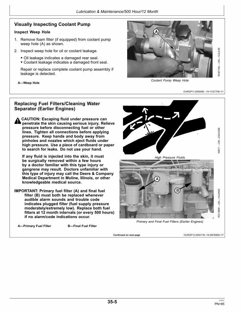
Lubrication & Maintenance/500 Hour/12 Month
OURGP11,0000080 1911OCT061/1
Continued on next page OURGP12,000011B 1926FEB081/7
Visually Inspecting Coolant PumpInspect Weep Hole
1. Remove foam filter (if equipped) from coolant pumpweep hole (A) as shown.
2. Inspect weep hole for oil or coolant leakage.
• Oil leakage indicates a damaged rear seal.• Coolant leakage indicates a damaged front seal.Repair or replace complete coolant pump assembly ifleakage is detected.
A—Weep Hole
RG8718A—UN—12JU
L99
Coolant Pump Weep Hole
Replacing Fuel Filters/Cleaning WaterSeparator (Earlier Engines)
CAUTION: Escaping fluid under pressure canpenetrate the skin causing serious injury. Relievepressure before disconnecting fuel or otherlines. Tighten all connections before applyingpressure. Keep hands and body away frompinholes and nozzles which eject fluids underhigh pressure. Use a piece of cardboard or paperto search for leaks. Do not use your hand.
If any fluid is injected into the skin, it mustbe surgically removed within a few hoursby a doctor familiar with this type injury organgrene may result. Doctors unfamiliar withthis type of injury may call the Deere & CompanyMedical Department in Moline, Illinois, or otherknowledgeable medical source.
IMPORTANT: Primary fuel filter (A) and final fuelfilter (B) must both be replaced wheneveraudible alarm sounds and trouble codeindicates plugged filter (fuel supply pressuremoderately/extremely low). Replace both fuelfilters at 12 month intervals (or every 500 hours)if no alarm/code indications occur.
A—Primary Fuel Filter B—Final Fuel Filter
X9811
—UN—23AUG88
High Pressure Fluids
RG13899—UN—14JU
N05
Primary and Final Fuel Filters (Earlier Engines)
355 010311
PN=85

Lubrication & Maintenance/500 Hour/12 Month
OURGP12,000011B 1926FEB082/7
OURGP12,000011B 1926FEB083/7
Continued on next page OURGP12,000011B 1926FEB084/7
Remove Primary Fuel Filter Element (Earlier Engines)
CAUTION: If engine has been running, engineand fuel filter housing may be hot.
1. Close fuel shutoff valve (if equipped).
2. Clean entire area surrounding fuel filter assembly tokeep debris from entering fuel system.
3. Remove cap from fuel filter housing by turningcounterclockwise by hand.
RG10302—UN—27MAY
04
Remove Primary Fuel Filter
4. Relieve vacuum in filter housing by operating handprimer until fuel filter “popsup”. If filter does not“popup” after about 30 strokes of primer, a smallscrewdriver may be used as shown to carefully pryunder filter flange to relieve vacuum in the housing.
RG10303—UN—27MAY
04
Relieve Vacuum
5. Lift filter element up in housing until filter seal clearsinlet tube inside housing. Continue to hold filtersuspended straight up in top of housing to drain fuelfrom filter.
6. Allow fuel to drain completely from filter into housing.Carefully begin rotating filter from housing as shownuntil completely upside down to ensure minimumleakage from fuel filter.
7. Place filter in container suitable for diesel fuel.
IMPORTANT: Reusing fuel filter once removed fromhousing may result in trapped air in the filter.This may cause fuel to overflow from the filterhousing during insertion of filter element,and/or cause the engine to stall and not restartwithout additional system purging.
RG10304—UN—02SEP99
Remove Filter Element
356 010311
PN=86

Lubrication & Maintenance/500 Hour/12 Month
OURGP12,000011B 1926FEB085/7
Continued on next page OURGP12,000011B 1926FEB086/7
Remove And Clean Water Separator Bowl(Earlier Engines)
1. Disconnect wiring connector from waterinfuel sensor.
2. Drain fuel from separator bowl.
3. Position a strap wrench (A) as close as possible totop edge of separator bowl. While applying pressurewith strap wrench, grip bowl and twist with other handas shown to remove bowl.
4. Clean separator bowl and dry it.
5. Install separator bowl and tighten by hand untilseal makes contact. Hand tighten to the followingspecification:
SpecificationWater SeparatorBowlToFilterHousing—Torque............................................................ 5 N∙m (44 lbin.)
6. Connect wiring to waterinfuel sensor.
RG10351—UN—13SEP99
Removing Water Separator Bowl
A—Strap Wrench
Install New Primary Fuel Filter Element(Earlier Engines)
1. Check to ensure that the fuel level in the filter housingis between the MIN (B) and MAX (A) fuel levelsindicated on the outside of the housing and on thecorresponding marks on the center tube. If the fuelis below the MIN level, then carefully open the fuelsupply shutoff valve a small amount (if equipped) toadd fuel.
Operate the hand primer to add more fuel if requiredor if the unit is not equipped with a fuel supply shutoffvalve.
IMPORTANT: Fuel level below the MIN indication mayresult in trapped air in the filter causing theengine to stall and not restart without additionalsystem purging. Fuel level above the MAXindication may cause fuel to overflow from thefilter housing during insertion of filter element.
2. Insert new (dry) fuel filter into filter housing.
3. Reinstall fuel filter cap and tighten to “handtight”condition.
RG10305—UN—02SEP99
Fuel Level In Filter Housing
A—Maximum Level (2 1/2Inches from Top ofHousing)
B—Minimum Level (5 Inchesfrom Top of Housing)
357 010311
PN=87
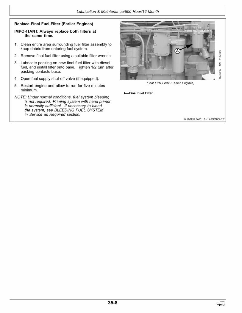
Lubrication & Maintenance/500 Hour/12 Month
OURGP12,000011B 1926FEB087/7
Replace Final Fuel Filter (Earlier Engines)
IMPORTANT: Always replace both filters atthe same time.
1. Clean entire area surrounding fuel filter assembly tokeep debris from entering fuel system.
2. Remove final fuel filter using a suitable filter wrench.
3. Lubricate packing on new final fuel filter with dieselfuel, and install filter onto base. Tighten 1/2 turn afterpacking contacts base.
4. Open fuel supply shutoff valve (if equipped).
5. Restart engine and allow to run for five minutesminimum.
NOTE: Under normal conditions, fuel system bleedingis not required. Priming system with hand primeris normally sufficient. If necessary to bleedthe system, see BLEEDING FUEL SYSTEMin Service as Required section.
RG13900—UN—14JU
N05
Final Fuel Filter (Earlier Engines)
A—Final Fuel Filter
358 010311
PN=88
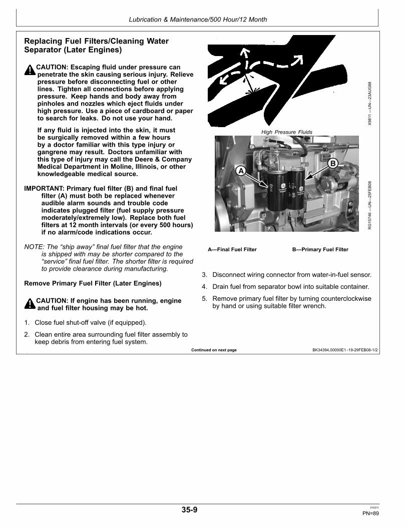
Lubrication & Maintenance/500 Hour/12 Month
Continued on next page BK34394,00000E1 1929FEB081/2
Replacing Fuel Filters/Cleaning WaterSeparator (Later Engines)
CAUTION: Escaping fluid under pressure canpenetrate the skin causing serious injury. Relievepressure before disconnecting fuel or otherlines. Tighten all connections before applyingpressure. Keep hands and body away frompinholes and nozzles which eject fluids underhigh pressure. Use a piece of cardboard or paperto search for leaks. Do not use your hand.
If any fluid is injected into the skin, it mustbe surgically removed within a few hoursby a doctor familiar with this type injury organgrene may result. Doctors unfamiliar withthis type of injury may call the Deere & CompanyMedical Department in Moline, Illinois, or otherknowledgeable medical source.
IMPORTANT: Primary fuel filter (B) and final fuelfilter (A) must both be replaced wheneveraudible alarm sounds and trouble codeindicates plugged filter (fuel supply pressuremoderately/extremely low). Replace both fuelfilters at 12 month intervals (or every 500 hours)if no alarm/code indications occur.
NOTE: The “ship away” final fuel filter that the engineis shipped with may be shorter compared to the“service” final fuel filter. The shorter filter is requiredto provide clearance during manufacturing.
Remove Primary Fuel Filter (Later Engines)
CAUTION: If engine has been running, engineand fuel filter housing may be hot.
1. Close fuel shutoff valve (if equipped).
2. Clean entire area surrounding fuel filter assembly tokeep debris from entering fuel system.
X9811
—UN—23AUG88
High Pressure Fluids
RG15746—UN—25FE
B08
A—Final Fuel Filter B—Primary Fuel Filter
3. Disconnect wiring connector from waterinfuel sensor.
4. Drain fuel from separator bowl into suitable container.
5. Remove primary fuel filter by turning counterclockwiseby hand or using suitable filter wrench.
359 010311
PN=89

Lubrication & Maintenance/500 Hour/12 Month
BK34394,00000E1 1929FEB082/2
Remove And Clean Water Separator Bowl(Later Engines)
1. Remove water separator bowl from primary fuelfilter by turning counterclockwise by hand or using asuitable strap wrench.
2. Clean separator bowl and dry it.
3. Lubricate new water separator bowl seal with thin filmof oil or fuel, and hand tighten to primary fuel filter.
SpecificationWater SeparatorBowlToPrimary FuelFilter—Torque................................... Hand Tighten to Primary Fuel Filter
Install New Primary Fuel Filter (Later Engines)
1. Lubricate new primary fuel filter seal with thin film ofoil or fuel.
2. Screw filter into header by turning clockwise until theseal contacts the header.
3. When seal contacts the header, tighten clockwise tothe following specification:
SpecificationPrimary FuelFilter—Torque....................................................Seal Contact + 1/2 to 3/4
Turn, Lubricated with Oil or Fuel
4. Connect waterinfuel sensor connector.
Replace Final Fuel Filter (Later Engines)
IMPORTANT: Always replace both filters atthe same time.
1. Clean entire area surrounding fuel filter assembly tokeep debris from entering fuel system.
2. Remove final fuel filter using a suitable filter wrench.
3. Lubricate new final fuel filter seal with thin film of oil orfuel, and screw filter into header by turning clockwiseuntil the seal contacts the header.
4. When seal contacts the header, tighten clockwise tothe following specification:
RG15747—UN—26FE
B08
A—Water Separator Bowl B—WaterInFuel Sensor
SpecificationFinal FuelFilter—Torque.................................................................Seal Contact + 1
Turn, Lubricated with Oil or Fuel
5. Open fuel supply shutoff valve (if equipped).
6. Turn ignition key to the ON position for 120 secondsto allow the system to prime itself.
7. Restart engine and allow to run for five minutesminimum.
NOTE: Under normal conditions, fuel system bleedingis not required. The auto prime feature isnormally sufficient. If necessary to bleed thesystem, see BLEEDING FUEL SYSTEM inService as Required section.
3510 010311
PN=90

Lubrication & Maintenance/500 Hour/12 Month
OURGP12,0000090 1912SEP061/1
OURGP11,0000110 1911OCT061/1
OURGP11,0000056 1911OCT061/1
Checking and Adjusting Engine SpeedsUse tachometer on the diagnostic gauge (A) toverify engine speeds. (Refer to ENGINE POWERRATINGS AND FUEL SYSTEM SPECIFICATIONS inSpecifications Section later in this manual for enginespeed specifications.) If engine speed adjustment isrequired, see your authorized servicing dealer or enginedistributor.
A—Diagnostic Gauge
RG13728—UN—11NOV04
Using Tachometer to Check Engine Speeds
Checking Engine MountsEngine mounting is the responsibility of the vehicle orgenerator manufacturer. Follow manufacturer’s guidelinesfor mounting specifications.
IMPORTANT: Use only Grade SAE 8 or higher gradeof hardware for engine mounting.
1. Check the engine mounting brackets (A), vibrationisolators, and mounting bolts on support frame andengine block for tightness. Tighten as necessary.
2. Inspect overall condition of vibration isolators, ifequipped. Replace isolators, as necessary, if rubberhas deteriorated or mounts have collapsed.
RG9905
—UN—06JAN99
Engine Mounting
A—Mounting Bracket
Checking Crankcase Vent Tube and Valve1. Loosen clamp on crankcase vent hose (A).
2. Remove crankcase vent valve (not shown) from rockerarm cover.
3. Remove crankcase vent valve from crankcase venthose and clean hose. Ensure hose is not plugged.
4. Shake crankcase vent valve. If free movement ofvalve is heard while shaking, valve can be reused.Replace valve if rattle is not heard.
5. Install the valve and vent hose. Attach valve with twoscrews. Tighten hose clamp securely.
A—Crankcase Vent Tube
RG14342—UN—27JU
L05
Crankcase Vent Tube
3511 010311
PN=91

Lubrication & Maintenance/500 Hour/12 Month
RG,RG34710,7569 1912SEP061/2
RG,RG34710,7569 1912SEP062/2
OURGP11,0000111 1912SEP061/1
Checking Air Intake SystemIMPORTANT: The air intake system must not leak.
Any leak, no matter how small, may result ininternal engine damage due to abrasive dirtand dust entering the intake system.
1. Inspect all intake hoses (piping) for cracks. Replaceas necessary.
2. Check clamps on piping which connect the air cleanerto the engine. Tighten clamps as necessary. This willhelp prevent dirt from entering the air intake systemthrough loose connections, causing internal enginedamage.
3. If engine has a rubber dust unloader valve (A), inspectthe valve on bottom of air cleaner for cracks orplugging. Replace as necessary.
RG8717A—UN—12JU
L99
Rubber Dust Unloader Valve
A—Dust Unloader Valve
4. Test air restriction indicator (B) for proper operation.Replace indicator as necessary.
IMPORTANT: ALWAYS REPLACE primary air cleanerelement when air restriction indicator is torn orvisibly dirty, or when it exceeds specifications orservice interval. A clogged air cleaner elementwill cause excessive intake restriction and areduced air supply to the engine.
5. Remove and inspect primary air cleaner element.Service as necessary. (See REPLACING AIRCLEANER FILTER ELEMENTS in Service asRequired section.)
If equipped with air intake restriction indicator gauge(B), check gauge and service air cleaner if it exceedsspecifications.
SpecificationMaximum Air IntakeRestriction—Vacuum.......................................................25 in. (625 mm)
H2O (6.25 kPa) (0.06 bar) (1.0 psi)
RG8719A—UN—12JU
L99
Air Restriction Indicator
B—Air Restriction Indicator
If not equipped with air restriction indicator, replaceair cleaner elements at 500 hours or 12 months,whichever occurs first.
Check Engine Electrical Ground ConnectionCheck engine ground connection to ensure it is tightand clean. See ELECTRICAL SYSTEM LAYOUT inTroubleshooting Section for ground location.
This inspection is necessary to prevent electrical arc,which can result in engine damage.
3512 010311
PN=92

Lubrication & Maintenance/500 Hour/12 Month
OURGP12,000013B 1912SEP061/3
Continued on next page OURGP12,000013B 1912SEP062/3
Checking Belt Tensioner Spring Tension andBelt WearBelt drive systems equipped with automatic (spring) belttensioners cannot be adjusted or repaired. The automaticbelt tensioners are designed to maintain proper belttension over the life of the belt. If tensioner spring tensionis not within specification, replace tensioner assembly.
Checking Belt Wear
The belt tensioner is designed to operate within the limit ofarm movement provided by the cast stops (A and B) whencorrect belt length and geometry is used.
Visually inspect cast stops (A and B) on belt tensionerassembly.
If the tensioner stop on swing arm (A) is hitting thefixed stop (B), check mounting brackets (alternator, belttensioner, idler pulley, etc.) and the belt length. Replacebelt as needed (see REPLACING FAN/ALTERNATORVBELTS in Service as Required section).
RG8742
—UN—03SEP99
Upper Tensioner Shown, Lower Tensioner Similar
A—Swing Arm Cast Stops B—Fixed Cast Stops
Checking Upper Tensioner Spring Tension
NOTE: While belt is loosened, inspect pulleys andbearings. Rotate and feel for hard turning orany unusual sounds. If pulleys or bearings needreplacement, see your John Deere dealer.
A belt tension gauge will not give an accurate measure ofthe belt tension when automatic spring tensioner is used.Measure tensioner spring tension using a torque wrenchand procedure outlined below:
1. Release tension on belt using a longhandled 1/2in.drive tool in square hole in end of tensioner arm.Remove belt from pulleys.
2. Release tension on tensioner arm and remove drivetool.
3. Put a mark (A) on swing arm of tensioner as shown.
4. Measure 21 mm (0.83 in.) from first mark (A) and puta second mark (B) on tensioner mounting base.
5. Rotate the swing arm using a torque wrench untilmarks (A and B) are aligned.
6. Record torque wrench measurement and comparewith specification below. Replace tensioner assemblyas required.
SpecificationUpper SpringTension—Torque................................................ 18–23 N∙m (13–17 lbft)
RG8727
—UN—10DEC97
Marks on Tensioner
RG8726
—UN—10DEC97
Align Marks
A—Mark on Swing Arm B—Mark on TensionerMounting Base
3513 010311
PN=93
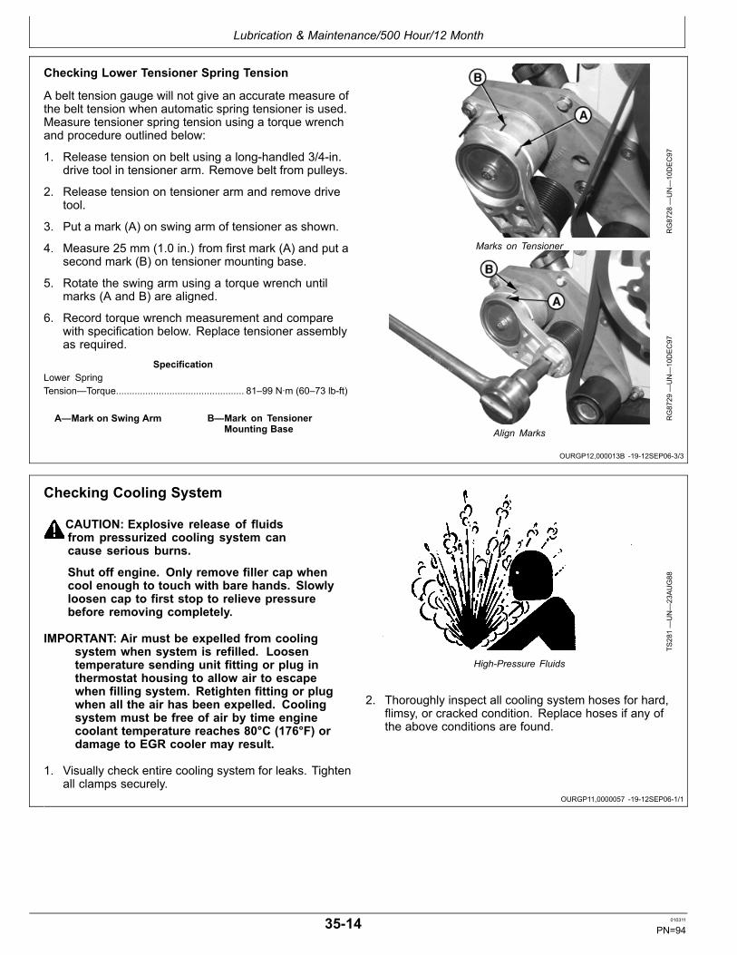
Lubrication & Maintenance/500 Hour/12 Month
OURGP12,000013B 1912SEP063/3
OURGP11,0000057 1912SEP061/1
Checking Lower Tensioner Spring Tension
A belt tension gauge will not give an accurate measure ofthe belt tension when automatic spring tensioner is used.Measure tensioner spring tension using a torque wrenchand procedure outlined below:
1. Release tension on belt using a longhandled 3/4in.drive tool in tensioner arm. Remove belt from pulleys.
2. Release tension on tensioner arm and remove drivetool.
3. Put a mark (A) on swing arm of tensioner as shown.
4. Measure 25 mm (1.0 in.) from first mark (A) and put asecond mark (B) on tensioner mounting base.
5. Rotate the swing arm using a torque wrench untilmarks (A and B) are aligned.
6. Record torque wrench measurement and comparewith specification below. Replace tensioner assemblyas required.
SpecificationLower SpringTension—Torque................................................ 81–99 N∙m (60–73 lbft)
A—Mark on Swing Arm B—Mark on TensionerMounting Base
RG8728
—UN—10DEC97
Marks on Tensioner
RG8729
—UN—10DEC97
Align Marks
Checking Cooling System
CAUTION: Explosive release of fluidsfrom pressurized cooling system cancause serious burns.
Shut off engine. Only remove filler cap whencool enough to touch with bare hands. Slowlyloosen cap to first stop to relieve pressurebefore removing completely.
IMPORTANT: Air must be expelled from coolingsystem when system is refilled. Loosentemperature sending unit fitting or plug inthermostat housing to allow air to escapewhen filling system. Retighten fitting or plugwhen all the air has been expelled. Coolingsystem must be free of air by time enginecoolant temperature reaches 80°C (176°F) ordamage to EGR cooler may result.
1. Visually check entire cooling system for leaks. Tightenall clamps securely.
TS281—UN—23AUG88
HighPressure Fluids
2. Thoroughly inspect all cooling system hoses for hard,flimsy, or cracked condition. Replace hoses if any ofthe above conditions are found.
3514 010311
PN=94

Lubrication & Maintenance/500 Hour/12 Month
DX,COOL9 1903NOV081/1
Testing Diesel Engine Coolant
Maintaining adequate concentrations of glycol andinhibiting additives in the coolant is critical to protect theengine and cooling system against freezing, corrosion,and cylinder liner erosion and pitting.
Test the coolant solution at intervals of 12 months or lessand whenever excessive coolant is lost through leaks oroverheating.
Coolant Test Strips
Coolant test strips are available from your John Deeredealer. These test strips provide a simple, effectivemethod to check the freeze point and additive levels ofyour engine coolant.
When Using John Deere COOLGARD II
John Deere COOLGARD™ II Premix and COOLGARDII Concentrate are maintenance free coolants for up to 6years or 6000 hours of operation, provided that the coolingsystem is topped off using only John Deere COOLGARDII Premix coolant. Test the coolant condition annuallywith coolant test strips designed for use with John Deere
COOLGARD II coolants. If the test strip chart indicatesthat additive is required, add John Deere COOLGARD IICOOLANT EXTENDER as directed.
Add only the recommended concentration of John DeereCOOLGARD II COOLANT EXTENDER. DO NOT addmore than the recommended amount.
When Using John Deere COOLGARD
Compare the test strip results to the supplemental coolantadditive (SCA) chart to determine the amount of inhibitingadditives in your coolant and whether more John DeereLIQUID COOLANT CONDITIONER should be added.
Add only the recommended concentration of John DeereLIQUID COOLANT CONDITIONER. DO NOT add morethan the recommended amount.
CoolScan and CoolScan PLUS
For a more thorough evaluation of your coolant, performa CoolScan™ or CoolScan PLUS™ analysis, whereavailable. See your John Deere dealer for information.
COOLGARD is a trademark of Deere & CompanyCoolScan is a trademark of Deere & CompanyCoolScan PLUS is a trademark of Deere & Company
3515 010311
PN=95

Lubrication & Maintenance/500 Hour/12 Month
OMRGP15,000012F 1912SEP061/1
Replenishing Supplemental Coolant Additives (SCAs) Between Coolant Changes
RG6261
—UN—08DEC97
Radiator Coolant Check
RG6262
—UN—05DEC97
JT07298 Coolant/Battery Tester
IMPORTANT: Do not add supplemental coolantadditives when the cooling system is drained andrefilled with John Deere ANTIFREEZE/SUMMERCOOLANT or John Deere COOLGARD®.
NOTE: If a system is to be filled with coolant that doesnot contain SCAs, the coolant must be precharged.Determine the total system capacity and premixwith 3% John Deere Coolant Conditioner.
Through time and use, the concentration of coolantadditives is gradually depleted during engine operation.Periodic replenishment of inhibitors is required, evenwhen John Deere ANTIFREEZE/SUMMER COOLANTis used. The cooling system must be recharged withadditional supplemental coolant additives available in theform of liquid coolant conditioner.
Maintaining the correct coolant conditioner concentration(SCAs) and freeze point is essential in your coolingsystem to protect against rust, liner pitting and corrosion,and freezeups due to incorrect coolant dilution.
John Deere LIQUID COOLANT CONDITIONER isrecommended as a supplemental coolant additive inJohn Deere engines.
DO NOT mix one brand of SCA with a different brand.
Test the coolant solution at 500 hours or 12 months ofoperation using either John Deere coolant test strips or a
COOLSCAN ® analysis. If a COOLSCAN ® analysis isnot available, recharge system per instructions printed onlabel of John Deere Liquid Coolant Conditioner.
IMPORTANT: ALWAYS maintain coolant at correctlevel and concentration. DO NOT operate enginewithout coolant for even a few minutes.
If frequent coolant makeup is required, theglycol concentration should be checkedwith JT07298 Coolant/Battery Tester toensure that the desired freeze point ismaintained. Follow manufacturer’s instructionsprovided with refractometer.
Add the manufacturer’s recommended concentration ofsupplemental coolant additive. DO NOT add more thanthe recommended amount.
The use of nonrecommended supplemental coolantadditives may result in additive dropout and gelation ofthe coolant.
If other coolants are used, consult the coolant supplierand follow the manufacturer’s recommendation for use ofsupplemental coolant additives.
See DIESEL ENGINE COOLANT and additionalinformation on coolant additives in Fuels, Lubricants andCoolants earlier in this manual for proper mixing of coolantingredients before adding to the cooling system.
COOLGARD is a registered trademark of Deere & CompanyCOOLSCAN is a registered trademark of Deere & Company.
3516 010311
PN=96

Lubrication & Maintenance/500 Hour/12 Month
OMRGP15,0000130 1912SEP061/1
Pressure Testing Cooling System
RG6557
—UN—20JAN93
D05104ST Tester
RG6558
—UN—20JAN93
Connect Gauge and Adapter to Filler Neck
A pressurized cooling system is required to protect enginefrom cavitation and oxidizing of coolant.
CAUTION: Explosive release of fluidsfrom pressurized cooling system cancause serious burns.
Shut off engine. Only remove filler cap whencool enough to touch with bare hands. Slowlyloosen cap to first stop to relieve pressurebefore removing completely.
Test Radiator Cap
1. Remove radiator cap and attach to D05104ST Testeras shown.
2. Pressurize cap to following specifications.1
SpecificationRadiator Cap—TestPressure........................................................ 103 kPa (1.03 bar) (15 psi)
Gauge should hold pressure for 10 seconds within thenormal range if cap is acceptable. If gauge does nothold pressure, replace radiator cap.
3. Remove the cap from gauge, turn it 180°, and retestcap. This will verify that the first measurement wasaccurate.
Test Cooling System
NOTE: Engine should be warmed up to testoverall cooling system.
1. Allow engine to cool; carefully remove radiator cap.
2. Fill radiator with coolant to normal operating level.
IMPORTANT: DO NOT apply excessive pressureto cooling system. Doing so may damageradiator and hoses.
3. Connect gauge and adapter to filler neck. Pressurizecooling system to the following specifications.1
SpecificationCooling System—TestPressure........................................................ 103 kPa (1.03 bar) (15 psi)
4. With pressure applied, check all cooling system hoseconnections, radiator, and engine for leaks.
If leakage is detected, correct as necessary andpressure test system again. If no leakage is detected,but the gauge indicated a drop in pressure, contactyour engine distributor or servicing dealer for furtherdiagnostics.
1Test pressures recommended are for Deere OEM cooling system for13.5 L engines. On specific vehicle applications, test cooling system andpressure cap according to the recommended pressure for that vehicle.
3517 010311
PN=97
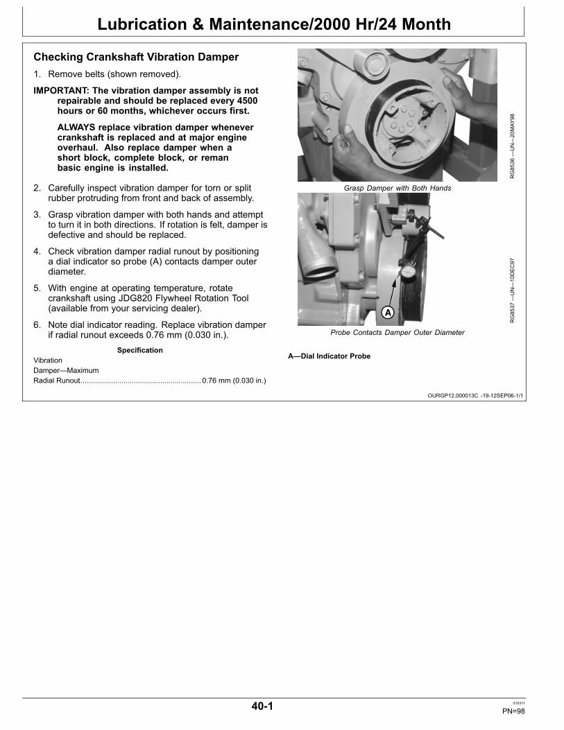
Lubrication & Maintenance/2000 Hr/24 Month
OURGP12,000013C 1912SEP061/1
Checking Crankshaft Vibration Damper1. Remove belts (shown removed).
IMPORTANT: The vibration damper assembly is notrepairable and should be replaced every 4500hours or 60 months, whichever occurs first.
ALWAYS replace vibration damper whenevercrankshaft is replaced and at major engineoverhaul. Also replace damper when ashort block, complete block, or remanbasic engine is installed.
2. Carefully inspect vibration damper for torn or splitrubber protruding from front and back of assembly.
3. Grasp vibration damper with both hands and attemptto turn it in both directions. If rotation is felt, damper isdefective and should be replaced.
4. Check vibration damper radial runout by positioninga dial indicator so probe (A) contacts damper outerdiameter.
5. With engine at operating temperature, rotatecrankshaft using JDG820 Flywheel Rotation Tool(available from your servicing dealer).
6. Note dial indicator reading. Replace vibration damperif radial runout exceeds 0.76 mm (0.030 in.).
SpecificationVibrationDamper—MaximumRadial Runout............................................................ 0.76 mm (0.030 in.)
RG8536
—UN—20MAY
98
Grasp Damper with Both Hands
RG8537
—UN—10DEC97
Probe Contacts Damper Outer Diameter
A—Dial Indicator Probe
401 010311
PN=98

Lubrication & Maintenance/2000 Hr/24 Month
OURGP11,0000058 1912SEP061/5
Continued on next page OURGP11,0000058 1912SEP062/5
Flushing and Refilling Cooling System
CAUTION: Explosive release of fluidsfrom pressurized cooling system cancause serious burns.
Shut off engine. Only remove filler cap whencool enough to touch with bare hands. Slowlyloosen cap to first stop to relieve pressurebefore removing completely.
NOTE: When John Deere COOLGARD is used, thedrain interval is 3000 hours or 36 months. Thedrain interval may be extended to 5000 hoursor 60 months of operation, provided that thecoolant is tested annually AND additivesare replenished, as needed, by adding asupplemental coolant additive (SCA).
If COOLGARD is not used, the flushing intervalremains at 2000 hours or 24 months of operation.
Drain old coolant, flush the entire cooling system, testthermostats, and fill with recommended clean coolant.
1. Pressure test entire cooling system and pressurecap if not previously done. (See PRESSURETESTING COOLING SYSTEM, in Lubrication andMaintenance/500 Hour/12 Month section.)
2. Slowly open the engine cooling system filler cap orradiator cap (A) to relieve pressure and allow coolantto drain faster.
TS281—UN—23AUG88
HighPressure Fluids
RG8735A—UN—03SEP99
Radiator Cap
A—Radiator Cap
3. Open oil cooler housing drain valve (A) on right side ofengine. Drain all coolant from engine block.
A—Drain Valve
RG8708A—UN—21JU
L99
Oil Cooler Housing Drain Valve
402 010311
PN=99

Lubrication & Maintenance/2000 Hr/24 Month
OURGP11,0000058 1912SEP063/5
Continued on next page OURGP11,0000058 1912SEP064/5
4. Open radiator drain valve (B) and drain all coolantfrom radiator.
B—Drain Valve
RG8730
—UN—03SEP99
Radiator Drain Valve
5. Remove six cap screws (A) from thermostat housingand remove housing. Remove three thermostats.Install housing (without thermostats) using old gasketand tighten cap screws to specifications.
SpecificationThermostat Cover CapScrews—Torque................................................... 50±10 N∙m (37±7 lbft)
6. Test thermostat opening temperature. (See TESTINGTHERMOSTATS OPENING TEMPERATURE later inthis section.)
7. Close all drain valves after coolant has drained.
CAUTION: Do not run engine longer than10 minutes. Doing so may cause engineto overheat which may cause burns whenradiator water is draining.
8. Fill the cooling system with clean water. Run theengine about 10 minutes to stir up possible rust orsediment.
9. Stop engine, pull off lower radiator hose and removeradiator cap. Immediately drain the water from systembefore rust and sediment settle.
10. After draining water, close drain valves. Reinstallradiator cap and radiator hose and clamp. Fill the
RG14338—UN—05JU
L05
Remove Thermostats
A—Cap Screws
cooling system with clean water and a heavy dutycooling system cleaner such as FLEETGUARD®RESTORE™ and RESTORE PLUS™. Followmanufacturer’s directions on label.
11. After cleaning the cooling system, drain cleaner and fillwith water to flush the system. Run the engine about10 minutes, remove radiator cap and pull off lowerradiator hose, then drain out flushing water.
FLEETGUARD is a registered trademark of CumminsEngine Company, Inc.RESTORE is a trademark of Fleetguard Inc.RESTORE PLUS is a trademark of Fleetguard Inc.
403 010311
PN=100

Lubrication & Maintenance/2000 Hr/24 Month
OURGP11,0000058 1912SEP065/5
12. Close all drain valves on engine and radiator. Reinstallradiator hose and tighten clamps securely. Installthermostats using a new gasket.
IMPORTANT: Air must be expelled from coolingsystem when system is refilled. Loosentemperature sending unit fitting or plug inthermostat housing to allow air to escapewhen filling system. Retighten fitting orplug after filling cooling system. Coolingsystem must be free of air by time enginecoolant temperature reaches 80°C (176°F) ordamage to EGR cooler may result.
13. Refill cooling system with fresh coolant until coolanttouches bottom of filler neck. (See followingspecification for cooling system capacity.) Installradiator cap.
Specification6135HF—Capacity...........................................................18.3 L (19.3 qt)
14. Run engine until it reaches operating temperature.This mixes the solution uniformly and circulates itthrough the entire system. The normal engine coolanttemperature range is 82°—92°C (180°—197°F).
RG8735
—UN—03SEP99
Flush Cooling System
15. After running engine, check coolant level and entirecooling system for leaks.
16. Inspect fan belt for wear and check belt tension(See Checking Belt Tensioner in Lubrication AndMaintenance 500 Hour/12 Months.
404 010311
PN=101

Lubrication & Maintenance/2000 Hr/24 Month
Continued on next page OURGP12,0000127 1929FEB081/3
Testing Thermostats Opening TemperatureTo Remove Thermostats
CAUTION: Explosive release of fluids frompressurized cooling system can cause seriousburns. DO NOT drain coolant until it hascooled below operating temperature. Alwaysloosen radiator pressure cap or drain valveslowly to relieve pressure.
1. Visually inspect area around thermostat housing forleaks.
2. Remove radiator pressure cap and partially draincooling system.
3. Remove six cap screws (A) from thermostat housingand remove housing (if not previously done).
4. Remove gasket and remove thermostats (B).
5. Test each thermostat for proper opening temperature.
A—Cap Screws B—Thermostats
RG14338—UN—05JU
L05
Remove Thermostat Housing
RG13896—UN—14JU
N05
Remove Gasket and Thermostats
405 010311
PN=102

Lubrication & Maintenance/2000 Hr/24 Month
Continued on next page OURGP12,0000127 1929FEB082/3
Testing Thermostats Opening Temperature
1. Remove thermostats.
2. Visually inspect thermostats for corrosion or damage.Replace thermostats as a matched set as necessary.
3. Inspect thermostat with ball valve in vent notch. If ballvalve movement is restricted, and cleaning does notfree ball valve, replace thermostat.
CAUTION: DO NOT allow thermostat orthermometer to rest against the side or bottomof container when heating water. Eithermay rupture if overheated.
4. Suspend thermostat and a thermometer in a containerof water.
5. Stir the water as it heats. Observe opening actionof thermostat and compare temperatures withspecification given in chart below.
NOTE: Due to varying tolerances of different supplies,initial opening and full open temperatures mayvary slightly from specified temperatures.
ENGINE/EGR THERMOSTAT TEST SPECIFICATIONS
Rating Initial Opening(EGR/Engine)
Full Open(Nominal)
82°C (180°F) 80—83°C (176—182°F)/80—84°C (176—183°F)
92°C (197°F)
RG5971
—UN—23NOV97
Thermostat and Thermometer in Water
6. Remove thermostat and observe its closing action asit cools. In ambient air the thermostat should closecompletely. Closing action should be smooth and slow.
7. If any one thermostat is defective, replace allthermostats.
406 010311
PN=103
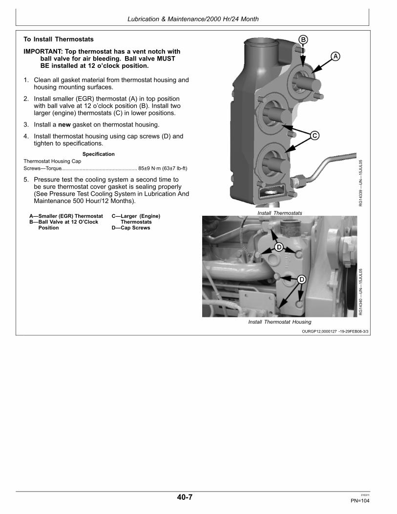
Lubrication & Maintenance/2000 Hr/24 Month
OURGP12,0000127 1929FEB083/3
To Install Thermostats
IMPORTANT: Top thermostat has a vent notch withball valve for air bleeding. Ball valve MUSTBE installed at 12 o’clock position.
1. Clean all gasket material from thermostat housing andhousing mounting surfaces.
2. Install smaller (EGR) thermostat (A) in top positionwith ball valve at 12 o’clock position (B). Install twolarger (engine) thermostats (C) in lower positions.
3. Install a new gasket on thermostat housing.
4. Install thermostat housing using cap screws (D) andtighten to specifications.
SpecificationThermostat Housing CapScrews—Torque..................................................... 85±9 N∙m (63±7 lbft)
5. Pressure test the cooling system a second time tobe sure thermostat cover gasket is sealing properly(See Pressure Test Cooling System in Lubrication AndMaintenance 500 Hour/12 Months).
A—Smaller (EGR) ThermostatB—Ball Valve at 12 O’Clock
Position
C—Larger (Engine)Thermostats
D—Cap Screws
RG14339—UN—15JU
L05
Install Thermostats
RG14340—UN—15JU
L05
Install Thermostat Housing
407 010311
PN=104
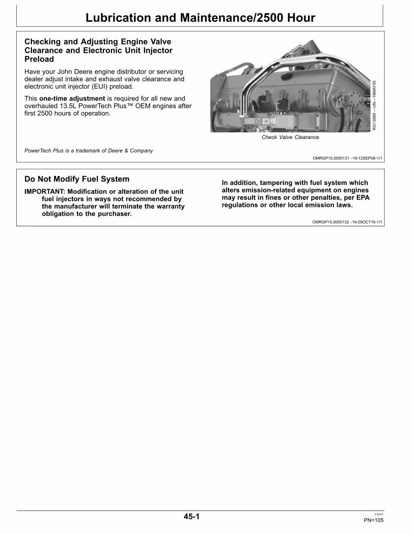
Lubrication and Maintenance/2500 Hour
OMRGP15,0000131 1912SEP061/1
OMRGP15,0000132 1929OCT101/1
Checking and Adjusting Engine ValveClearance and Electronic Unit InjectorPreloadHave your John Deere engine distributor or servicingdealer adjust intake and exhaust valve clearance andelectronic unit injector (EUI) preload.
This onetime adjustment is required for all new andoverhauled 13.5L PowerTech Plus™ OEM engines afterfirst 2500 hours of operation.
RG13889—UN—19MAY
05
Check Valve Clearance
PowerTech Plus is a trademark of Deere & Company
Do Not Modify Fuel SystemIMPORTANT: Modification or alteration of the unit
fuel injectors in ways not recommended bythe manufacturer will terminate the warrantyobligation to the purchaser.
In addition, tampering with fuel system whichalters emissionrelated equipment on enginesmay result in fines or other penalties, per EPAregulations or other local emission laws.
451 010311
PN=105

Service as Required
OURGP11,0000048 1923AUG101/1
OURGP11,000005A 1912OCT061/1
Additional Service InformationThis is not a detailed service manual. If you want moredetailed service information, contact your John Deeredealer or engine distributor.
RG4624
—UN—15DEC88
Component Technical Manuals
Adding Coolant
CAUTION: Explosive release of fluidsfrom pressurized cooling system cancause serious burns.
Shut off engine. Only remove filler cap whencool enough to touch with bare hands. Slowlyloosen cap to first stop to relieve pressurebefore removing completely.
IMPORTANT: Never pour cold liquid into a hotengine, as it may crack cylinder head orblock. DO NOT operate engine withoutcoolant for even a few minutes.
John Deere Cooling System Sealer maybe added to the radiator to stop leaks ona temporary or emergency basis only. DONOT use any other stopleak additives in thecooling system. Leaks should be permanentlyrepaired as quickly as possible.
Air must be expelled from cooling systemwhen coolant is added. Cooling systemmust be free of air by time engine coolanttemperature reaches 80°C (176°F) or damageto EGR cooler may result.
1. Loosen temperature sending unit fitting or plug inthermostat housing to allow air to escape when fillingsystem.
IMPORTANT: When adding coolant to the system,use the appropriate coolant solution. (SeeDIESEL ENGINE COOLANTS, SUPPLEMENTALADDITIVE INFORMATION in Fuels, Lubricants,and Coolant section for mixing of coolantingredients before adding to cooling system.)
Do not overfill cooling system. A pressurizedsystem needs space for heat expansion withoutoverflowing at top of radiator.
TS281—UN—23AUG88
HighPressure Fluid
RG8735
—UN—03SEP99
Fill Cooling System
2. Fill until coolant level touches bottom of radiator fillerneck or to “FULL HOT” mark on coolant recovery tank..
3. Check freeze temperature protection.
4. Tighten plugs and fittings after filling cooling system.
5. Run engine for 10 minutes to remove any air fromsystem. Top off coolant level if required.
501 010311
PN=106

Service as Required
Continued on next page RG,RG34710,7591 1912SEP061/2
Replacing Air Cleaner Filter ElementsIMPORTANT: ALWAYS REPLACE primary air
cleaner element when air restriction indicatorshows a vacuum of 625 mm (25 in.) H2O,is torn, or visibly dirty.
NOTE: This procedure applies to John Deere air cleanerkits. Refer to manufacturer’s instructions forservicing air cleaners not supplied by John Deere.
1. Remove wing nut (A) and remove canister cover andprimary filter assembly (B) from canister.
IMPORTANT: Remove secondary (safety) air cleanerelement (E) ONLY for replacement. DO NOTattempt to clean, wash, or reuse secondaryelement. Replacement of secondary element isusually necessary ONLY when primary elementhas a hole in it or restriction indicator greendot (•) has disappeared from window.
2. Thoroughly clean all dirt from inside canister.
3. Squeeze dust unloader valve (C) on canister toremove all dust.
4. Observe secondary (safety) element restrictionindicator/retaining nut (D). If green dot (•) hasdisappeared from window, replace secondary element.
5. To replace secondary element, remove restrictionindicator/retaining nut and secondary element.Immediately replace secondary element with newelement to prevent dust from entering air intakesystem. Tighten restriction indicator/retaining nut tospecifications.
SpecificationAir Filter RestrictionIndicator/RetainingNut—Torque................................................................... 14 N∙m (10 lbft)
A—Wing NutB—Primary Filter AssemblyC—Unloader Valve
D—Restriction Indicator/Retaining Nut
E—Secondary Air CleanerElement
RG8731
—UN—03SEP99
Wing Nut and Unloader Valve
RG8732
—UN—03SEP99
Replacing Primary Air Filter Element
RG8733
—UN—03SEP99
Indicator/Retaining Nut for Replacing Secondary Air Filter Element
502 010311
PN=107

Service as Required
RG,RG34710,7591 1912SEP062/2
OMRGP15,0000133 1929FEB081/1
6. Install new primary assembly element and tightenwing nut securely.
IMPORTANT: Whenever the air cleaner has beenserviced or had cover removed, ALWAYS fullydepress the air restriction indicator reset button(if equipped) to assure accurate readings.
7. If equipped, fully depress air restriction indicator resetbutton (A) and release to reset indicator.
A—Air Restriction IndicatorReset Button R
G8719B—UN—03SEP99
Air Restriction Indicator Reset Button
Draining Fuel Filter Water Separator BowlYour engine is equipped with a sensor that detects thepresence of water in separator bowl mounted below fuelfilter. This sensor will illuminate the red “STOP ENGINE”warning light (A) on instrument panel and also soundan audible alarm (B). A diagnostic trouble code (DTC)displayed on the diagnostic gauge will indicate that thereis water in the fuel bowl (see LISTING OF DIAGNOSTICTROUBLE CODES in Section 55).
ALWAYS STOP ENGINE IMMEDIATELY and drain waterseparator bowl when these warnings occur.
1. Drain water and contaminants from water separatorsediment bowl by opening drain valve (C) andoperating primer until fuel is clear of water.
2. Close drain valve.
A—Warning LightB—Audible Alarm
C—Drain Valve
RG13882—UN—06MAY
05
Warning Light And Audible Alarm On Panel
RG12773—UN—23JAN03
Draining Fuel Sediment Bowl (Earlier Engines shown)
503 010311
PN=108

Service as Required
OURGP11,000005C 1912SEP061/1
OURGP11,000005D 1911OCT061/1
Bleeding Fuel System (Earlier Engines)
CAUTION: Escaping fluid under pressure canpenetrate the skin causing serious injury. Relievepressure before disconnecting fuel or otherlines. Tighten all connections before applyingpressure. Keep hands and body away frompinholes and nozzles which eject fluids underhigh pressure. Use a piece of cardboard or paperto search for leaks. Do not use your hand.
If any fluid is injected into the skin, it mustbe surgically removed within a few hoursby a doctor familiar with this type injury organgrene may result. Doctors unfamiliar withthis type of injury may call the Deere & CompanyMedical Department in Moline, Illinois, or otherknowledgeable medical source.
IMPORTANT: Fuel filter must be replaced wheneveraudible alarm sounds and trouble codeindicates plugged filter (fuel supply pressuremoderately/extremely low). Replace fuel filterat 12 month intervals (or every 500 hours) ifno alarm/code indications occur.
NOTE: Under normal conditions, fuel system bleedingis not required. Priming system with hand primer(B) is normally sufficient. If necessary to bleedthe system, use the following procedure.
1. Drain water and contaminants from water separatorsediment bowl by opening drain valve (C) andoperating primer (B) until fuel is clear of water.
2. Attach an open line to diagnostic port (A) and placeend of line in suitable container for diesel fuel.
3. Pump hand primer (B) until a steady flow of fuel(without bubbles) comes out of line.
X9811
—UN—23AUG88
High Pressure Fluids
RG12829—UN—24JAN03
Bleeding Fuel System
A—Diagnostic PortB—Hand Primer
C—Water Drain Valve
4. Disconnect line from diagnostic port.
5. Start engine and run for five minutes.
NOTE: If engine will not start after bleeding, contactyour servicing dealer for an air bleed kit.
Bleeding Fuel System (Later Engines)NOTE: Normally, the fuel system on these engines is
selfpriming and selfbleeding, and does not requirea bleeding procedure by the operator.
If engine will not start after filter changes, turn ignition keyON for 60 seconds to prime the fuel system. It may benecessary to turn the key off and on again to reprime thesystem before starting.
504 010311
PN=109

Service as Required
OURGP12,000013D 1912SEP061/2
OURGP12,000013D 1912SEP062/2
Replacing Fan/Alternator VBeltsRefer to CHECKING BELT TENSIONER SPRINGTENSION AND BELT WEAR in Lubrication andMaintenance/500 Hour/12 Month section to determine ifVbelts need replacing.
NOTE: While belt is removed, inspect pulleys andbearings. Rotate and feel for hard turning orany unusual sounds. If pulleys or bearings needreplacement, see your John Deere dealer.
NOTE: This engine is equipped with automatic belttensioners which do not require adjustment.
To Replace Lower VBelt
IMPORTANT: ALWAYS replace belts as a matched set.
1. Release tension on lower belt using a 3/4in. drive toolin square hole in end of lower tensioner arm (A).
2. Remove Vbelt from pulleys and discard belt.
3. Install new belt; be sure that belt is correctly seatedin all pulley grooves. (See VBELT ROUTING, laterin this section.)
RG8743
—UN—03SEP99
Lower Tensioner
A—Lower Tensioner Arm
4. Release belt tensioner to apply tension to belt.Remove drive tool.
5. Visually check belt alignment before starting engine.
6. Start engine and visually check belt alignment.
To Replace Upper VBelt
IMPORTANT: ALWAYS replace belts as a matched set.
1. Remove lower Vbelt as detailed earlier.
2. Release tension on upper Vbelt using a 1/2in. drivetool in upper tensioner arm (A).
3. Remove Vbelt from pulleys and discard belt.
4. Install new belt; be sure that belt is correctly seatedin all pulley grooves. (See VBELT ROUTING, laterin this section.)
5. Slowly release belt tensioner to apply tension to belt.Remove drive tool.
6. Check belt alignment before starting engine.
7. Install lower Vbelt as detailed earlier.
8. Start engine and visually check belt alignment.
RG8744
—UN—03SEP99
Upper Tensioner
A—Upper Tensioner Arm
505 010311
PN=110

Service as Required
RG,RG34710,7595 1912SEP061/1
OMRGP15,0000134 1908NOV101/1
DPSG,RG34710,104 1912SEP061/1
VBelt Routing
RG8745
—UN—03SEP99
Lower VBelt
RG8746
—UN—03SEP99
Upper VBelt
Lower Vbelt MUST BE removed before removing upperVbelt. Reverse sequence for Vbelt installation.
Checking FusesThe main system fuse is located in the enginewiring harness. See ENGINE WIRING DIAGRAM inTroubleshooting section.
1. Open fuse holder in wiring harness.
2. Check fuse and replace as necessary with appropriatefuse.
Fuses are also provided in wiring for engine control unit(ECU) (20amp) and fuel filters (15amp). (See ENGINEWIRING DIAGRAM in Troubleshooting Section.)
Air CompressorsAir compressors are offered as options with John DeereOEM engines to provide compressed air to operateairpowered devices like vehicle air brakes.
Air compressors are enginedriven piston types. Theyare either air cooled or cooled with engine coolant.The compressors are lubricated with engine oil. Thecompressor runs continuously as gear or spline drivenby the auxiliary drive of the engine but has “loaded” and“unloaded” operating modes. This is controlled by thevehicle’s air system (refer to vehicle technical manual forcomplete air system checks and services).
See your John Deere engine distributor or servicing dealerfor diagnostic and troubleshooting information. If diagnosisleads to an internal fault in the compressor, replace thecomplete compressor as a new or remanufactured unit.
RG9530
—UN—24MAR99
Air Compressor (Optional)
506 010311
PN=111

Service as Required
OUOD006,0000065 1912SEP061/1
Rear Power TakeOff (PTO)
CAUTION: Entanglement in rotating drivelinecan cause serious injury or death. Keep shieldon PTO driveshaft between clutch housing andthe engine driven equipment at all times duringengine operation. Wear close fitting clothing.Stop the engine and be sure PTO driveline isstopped before making adjustments.
If option 9201 or 9207 is ordered to make therear PTO compatible with other manufacturer’sdrivelines, be sure that proper shielding isin place before operation.
CAUTION: Metal surfaces of PTO housing may behot to the touch during operation or at shutdown.
The optional engine rear power takeoff (PTO) from JohnDeere transfers engine power to auxiliary equipmentor moving components which may be mounted on thevehicle or trailed behind. It is an enginedriven PTO whichoperates whenever the engine is running.
IMPORTANT: An additional 4.0 L (4.2 qt.) of oil mustbe added to the crankcase for lubrication of therear PTO option. (See ENGINE CRANKCASE OILFILL QUANTITIES in the Specifications section.)
Proper performance of the power takeoff unit will berelated to the care it is given. Periodically check for anyoil leaks that may occur.
If the power takeoff does not work properly, contact yourauthorized servicing dealer or engine distributor.
TS1644
—UN—22AUG95
Rotating Drivelines
RG12593—UN—06SEP02
John Deere Rear PTO (Optional)
507 010311
PN=112

Troubleshooting
OMRGP15,0000135 1912SEP061/1
General Troubleshooting InformationTroubleshooting engine problems can be difficult. A listof possible engine problems that may be encountered isprovided in this section accompanied by possible causesand corrections.
An engine wiring diagram is provided later in this sectionto help isolate electrical problems on power units usingJohn Deere wiring harness and instrument (gauge) panel.The illustrated diagrams and troubleshooting informationare of a general nature; final design of the overall systemfor your engine application may be different. See yourengine distributor or servicing dealer if you are in doubt.
The engine control unit (ECU) has the ability to detectproblems internally and in the electronic control system.This includes determining if any of the sensor inputvoltages are too high or too low, if the camshaft andcrankshaft position sensor inputs are valid, and if the unitinjector solenoids are responding properly.
If the ECU detects a problem with the electronic controlsystem a diagnostic trouble code (DTC) specific to thefailed system will be stored in the ECU’s memory.
There are two types of DTC’s:
• Active• Inactive (stored)
Active DTCs indicate that the failure is occurring. Thesetype of failures are sometimes called “hard” failures. Theycan be accessed on the diagnostic gauge (A) on theinstrument panel.
Inactive DTCs indicate that a failure has occurred in thepast, but is not currently occurring. This type of “stored”DTC can be caused by an “intermittent” failure. Thesecould be problems such as a bad connection or a wireintermittently shorting to ground.
If a sensor or wiring fails and a DTC is active for thesensor, the ECU will use a substitute “limp home” value inits calculations to continue engine operation.
RG13728—UN—11NOV04
Diagnostic Gauge On Panel
A—Diagnostic Gauge
NOTE: All engines have electronic control systemswhich may send diagnostic trouble codes to signalproblems (see DISPLAYING OF DIAGNOSTICTROUBLE CODES, later in this section).
To access DTC’s with the diagnostic gauge,see Section 15 of this manual.
1. If fault codes are present, perform thesuggested corrective actions.
2. If this does not correct the engine problem,contact your servicing dealer.
3. If engine has problems but no faultcodes are displayed, refer to ENGINETROUBLESHOOTING later in this sectionfor problems and solutions.
551 010311
PN=113

Troubleshooting
OURGP12,000013E 1912SEP061/1
OURGP12,00000F0 1924AUG101/1
Instrument Panel Method for RetrievingDiagnostic Trouble CodesIMPORTANT: Care should be used during diagnostic
procedures to avoid damaging the terminalsof connectors, sensors, and actuators.Probes should not be poked into or aroundthe terminals or damage will result. Probesshould only be touched against the terminalsto make measurements.
Diagnosis of the Deere electronic control system onengines with Deere electronic instrument panel should beperformed as follows:
1. Make sure all engine mechanical and other systemsnot related to the electronic control system are operatingproperly. (See ENGINE TROUBLESHOOTING later inthis section.)
NOTE: Diagnostic gauge (A) uses the menu key (B)to access various engine functions, two arrowkeys (C) to scroll through the engine parameterlist and view the menu list, and an enter key(D) for selecting highlighted items.
2. Read and record DTC(s) displayed on LCD ofdiagnostic gauge (A). For procedure to access diagnostictrouble codes, refer to “Using Diagnostic Gauge to AccessEngine Information”, earlier in this manual.
RG13740—UN—11NOV04
Trouble Code Display On Instrument Panel
A—Diagnostic GaugeB—Menu Key
C—Arrow KeysD—Enter Key
3. Go to the LISTING OF DIAGNOSTIC TROUBLECODES (DTCs) later in this section, to interpret to theDTC(s) present.
4. Contact your nearest engine distributor or servicingdealer with a list of DTC(s) so that necessary repairs canbe made.
Displaying Of Diagnostic Trouble Codes (DTCs)
SPN/FMI CODES
Stored and active diagnostic trouble codes are output onthe diagnostic gauge on the Deere electronic instrumentpanel according to the J1939 standard as a twopart codeas shown on the tables on the following pages.
The first part is a Suspect Parameter Number (SPN)followed by a Failure Mode Identifier (FMI) code. In orderto determine the exact failure, both parts (SPN and FMI)of the code are needed.
The SPN identifies the system or the component that hasthe failure; for example SPN 000110 indicates a failure inthe engine coolant temperature circuit.
The FMI identifies the type of failure that has occurred; forexample FMI 03 indicates value above normal. CombiningSPN 000110 with FMI 03 yields a fault code “enginecoolant temperature input voltage too high”. A correctiveaction will also be displayed, “check sensor and wiring”. Ifthis check does not solve the engine fault, contact yourservicing dealer.
Always contact your servicing dealer for help in correctingunsolved diagnostic trouble codes which are displayedfor your engine.
552 010311
PN=114

Troubleshooting
Continued on next page OURGP11,000005E 1912OCT061/5
Listing of Diagnostic Trouble Codes (DTCs)NOTE: Not all of these codes are used in all
engine applications.
NOTE: If the corrective actions below do not solve theengine fault, contact your servicing dealer.
SPN FMI Fault Corrective Action000028 03...... Throttle #3 Voltage Out of Range High .............................. Check Sensor and Wiring
04...... Throttle #3 Voltage Out of Range Low ............................... Check Sensor and Wiring000029 03...... Throttle #2 Voltage Out of Range High .............................. Check Sensor and Wiring
04...... Throttle #2 Voltage Out of Range Low ............................... Check Sensor and Wiring000091 03...... Throttle #1 Signal Out of Range High................................ Check Sensor and Wiring
04...... Throttle #1 Signal Out of Range Low ................................ Check Sensor and Wiring09...... Throttle #1 Communication Signal Erratic........................... Check Sensor and Wiring
000094 01...... Fuel Pressure Voltage Out of RangeMost Low ................... Check Sensor and Wiring03...... Low Pressure Fuel Signal Out of Range High...................... Check Sensor and Wiring04...... Low Pressure Fuel Signal Out of Range Low ...................... Check Sensor and Wiring10...... When The Engine Is Motoring And The High Pressure Pump Is
Off, The Rail Pressure Drops Too Fast .............................. Check Sensor and Wiring
13...... Rail Pressure Test Has Failed ......................................... Check Sensor and Wiring17...... Low Fuel Pressure Signal Slightly Low .............................. Check Fuel Supply and Prime System
000097 03...... Water in Fuel Signal Out Of Range High ............................ Check Sensor and Wiring04...... Water in Fuel Signal Out Of Range Low............................. Check Sensor and Wiring16...... Water in Fuel Detected.................................................. Stop and Drain Water Separator
000100 01...... Engine Oil Pressure Extremely Low.................................. Check Oil Level03...... Engine Oil Pressure Signal Out of Range High .................... Check Sensor and Wiring04...... Engine Oil Pressure Signal Out of Range Low..................... Check Sensor and Wiring18...... Engine Oil Pressure Signal Moderately Low ....................... Check Oil Level31...... Engine Oil Pressure Invalid ............................................ Contact Servicing Dealer
000102 02...... Intake Manifold Pressure Signal Invalid ............................. Check Sensor and Wiring03...... Intake Manifold Pressure Signal Out of Range .................... Check Sensor and Wiring04...... Intake Manifold Pressure Signal Out of Range Low .............. Check Sensor and Wiring
000103 00...... Turbocharger Speed Signal Extremely High........................ Check Sensor and Wiring05...... Turbocharger Speed Sensor Circuit Has High Resistance ...... Check Sensor and Wiring08...... Turbocharger Speed Missing .......................................... Check Sensor and Wiring31...... Turbocharger Speed Signal Missing ................................. Check Sensor and Wiring
000105 00...... Intake Manifold Air Temperature Signal Extremely High ......... Check Air Cleaner, Aftercooler, or Ambient Temperature03...... Intake Manifold Air Temperature Signal Out Of Range High ....
Check Sensor and Wiring04...... Intake Manifold Air Temperature Signal Out Of Range Low.....
Check Sensor and Wiring15...... Intake Manifold Air Temperature Signal Slightly High............. Check Sensor and Wiring16...... Intake Manifold Air Temperature Signal Moderately High........ Check Air Cleaner, Aftercooler, or Ambient Temperature
000107 00...... Air Filter Pressure Differential Extremely High ..................... Check for Plugged Air Filter000108 02...... Barometric Pressure Signal Invalid ................................... Check for Plugged Air Filter000110 00...... Engine Coolant Temperature Signal Extremely High ............. Check Cooling System, Reduce Power
03...... Engine Coolant Temperature Signal Out Of Range High ........ Check Sensor and Wiring04...... Engine Coolant Temperature Signal Out Of Range Low ......... Check Sensor and Wiring15...... Engine Coolant Temperature Signal Slightly High................. Check Cooling System, Reduce Power16...... Engine Coolant Temperature Signal Moderately High............ Check Cooling System, Reduce Power17...... Engine Coolant Temperature Signal Slightly Low ................. Check Cooling System
000111 01...... Loss Of Coolant Detected .............................................. Check Operator’s Manual000157 01...... LowPressure Fuel Pressure Low Most Severe Level .......... Check Sensor and Wiring
03...... Fuel Rail Pressure Signal Out of Range High ...................... Check Sensor and Wiring04...... Fuel Rail Pressure Signal Out of Range Low....................... Check Sensor and Wiring16...... LowPressure Fuel Pressure High.................................... Check Sensor and Wiring
553 010311
PN=115
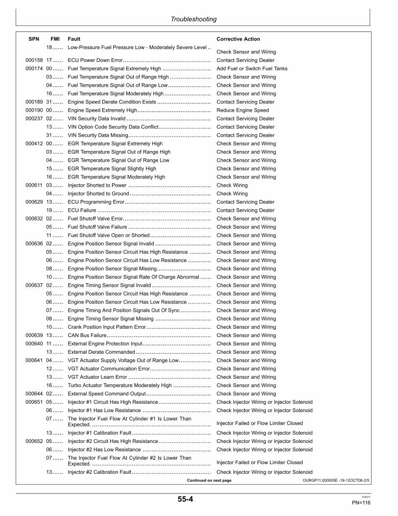
Troubleshooting
Continued on next page OURGP11,000005E 1912OCT062/5
SPN FMI Fault Corrective Action18...... LowPressure Fuel Pressure Low Moderately Severe Level ..
Check Sensor and Wiring000158 17...... ECU Power Down Error................................................. Contact Servicing Dealer000174 00...... Fuel Temperature Signal Extremely High ........................... Add Fuel or Switch Fuel Tanks
03...... Fuel Temperature Signal Out of Range High ....................... Check Sensor and Wiring04...... Fuel Temperature Signal Out of Range Low........................ Check Sensor and Wiring16...... Fuel Temperature Signal Moderately High .......................... Check Sensor and Wiring
000189 31...... Engine Speed Derate Condition Exists .............................. Contact Servicing Dealer000190 00...... Engine Speed Extremely High......................................... Reduce Engine Speed000237 02...... VIN Security Data Invalid ............................................... Contact Servicing Dealer
13...... VIN Option Code Security Data Conflict............................. Contact Servicing Dealer31...... VIN Security Data Missing.............................................. Contact Servicing Dealer
000412 00...... EGR Temperature Signal Extremely High Check Sensor and Wiring03...... EGR Temperature Signal Out of Range High Check Sensor and Wiring04...... EGR Temperature Signal Out of Range Low Check Sensor and Wiring15...... EGR Temperature Signal Slightly High Check Sensor and Wiring16...... EGR Temperature Signal Moderately High Check Sensor and Wiring
000611 03...... Injector Shorted to Power .............................................. Check Wiring04...... Injector Shorted to Ground ............................................. Check Wiring
000629 13...... ECU Programming Error................................................ Contact Servicing Dealer19...... ECU Failure ............................................................... Contact Servicing Dealer
000632 02...... Fuel Shutoff Valve Error................................................. Check Sensor and Wiring05...... Fuel Shutoff Valve Failure .............................................. Check Sensor and Wiring11 ...... Fuel Shutoff Valve Open or Shorted.................................. Check Sensor and Wiring
000636 02...... Engine Position Sensor Signal Invalid ............................... Check Sensor and Wiring05...... Engine Position Sensor Circuit Has High Resistance ............ Check Sensor and Wiring06...... Engine Position Sensor Circuit Has Low Resistance ............. Check Sensor and Wiring08...... Engine Position Sensor Signal Missing.............................. Check Sensor and Wiring10...... Engine Position Sensor Signal Rate Of Charge Abnormal ...... Check Sensor and Wiring
000637 02...... Engine Timing Sensor Signal Invalid ................................. Check Sensor and Wiring05...... Engine Position Sensor Circuit Has High Resistance ............ Check Sensor and Wiring06...... Engine Position Sensor Circuit Has Low Resistance ............. Check Sensor and Wiring07...... Engine Timing And Position Signals Out Of Sync ................. Check Sensor and Wiring08...... Engine Timing Sensor Signal Missing ............................... Check Sensor and Wiring10...... Crank Position Input Pattern Error.................................... Check Sensor and Wiring
000639 13...... CAN Bus Failure.......................................................... Check Sensor and Wiring000640 11 ...... External Engine Protection Input...................................... Check Sensor and Wiring
13...... External Derate Commanded.......................................... Check Sensor and Wiring000641 04...... VGT Actuator Supply Voltage Out of Range Low.................. Check Sensor and Wiring
12...... VGT Actuator Communication Error.................................. Check Sensor and Wiring13...... VGT Actuator Learn Error .............................................. Check Sensor and Wiring16...... Turbo Actuator Temperature Moderately High ..................... Check Sensor and Wiring
000644 02...... External Speed Command Output.................................... Check Sensor and Wiring000651 05...... Injector #1 Circuit Has High Resistance ............................. Check Injector Wiring or Injector Solenoid
06...... Injector #1 Has Low Resistance ...................................... Check Injector Wiring or Injector Solenoid07...... The Injector Fuel Flow At Cylinder #1 Is Lower Than
Expected. .................................................................. Injector Failed or Flow Limiter Closed
13...... Injector #1 Calibration Fault............................................ Check Injector Wiring or Injector Solenoid000652 05...... Injector #2 Circuit Has High Resistance ............................. Check Injector Wiring or Injector Solenoid
06...... Injector #2 Has Low Resistance ...................................... Check Injector Wiring or Injector Solenoid07...... The Injector Fuel Flow At Cylinder #2 Is Lower Than
Expected. .................................................................. Injector Failed or Flow Limiter Closed
13...... Injector #2 Calibration Fault............................................ Check Injector Wiring or Injector Solenoid
554 010311
PN=116

Troubleshooting
Continued on next page OURGP11,000005E 1912OCT063/5
SPN FMI Fault Corrective Action000653 05...... Injector #3 Circuit Has High Resistance ............................. Check Injector Wiring or Injector Solenoid
06...... Injector #3 Has Low Resistance ...................................... Check Injector Wiring or Injector Solenoid07...... The Injector Fuel Flow At Cylinder #3 Is Lower Than
Expected. .................................................................. Injector Failed or Flow Limiter Closed
13...... Injector #3 Calibration Fault............................................ Check Injector Wiring or Injector Solenoid000654 05...... Injector #4 Circuit Has High Resistance ............................. Check Injector Wiring or Injector Solenoid
06...... Injector #4 Has Low Resistance ...................................... Check Injector Wiring or Injector Solenoid07...... The Injector Fuel Flow At Cylinder #4 Is Lower Than
Expected. .................................................................. Injector Failed or Flow Limiter Closed
13...... Injector #4 Calibration Fault............................................ Check Injector Wiring or Injector Solenoid000655 05...... Injector #5 Circuit Has High Resistance ............................. Check Injector Wiring or Injector Solenoid
06...... Injector #5 Has Low Resistance ...................................... Check Injector Wiring or Injector Solenoid07...... The Injector Fuel Flow At Cylinder #5 Is Lower Than
Expected. ..................................................................Injector Failed or Flow Limiter Closed
13...... Injector #5 Calibration Fault............................................ Check Injector Wiring or Injector Solenoid000656 05...... Injector #6 Circuit Has High Resistance ............................. Check Injector Wiring or Injector Solenoid
06...... Injector #6 Has Low Resistance ...................................... Check Injector Wiring or Injector Solenoid07...... The Injector Fuel Flow At Cylinder #6 Is Lower Than
Expected. .................................................................. Injector Failed or Flow Limiter Closed
13...... Injector #6 Calibration Fault............................................ Check Injector Wiring or Injector Solenoid000676 03...... Glow Plug Relay.......................................................... Contact Servicing Dealer
05...... Glow Plug Relay.......................................................... Contact Servicing Dealer000729 03...... Inlet Air Heater Signal Received When Not Expected............ Contact Servicing Dealer
04...... Inlet Air Heater Signal Not Received When Expected............ Contact Servicing Dealer000833 02...... Rack Position Sensor Error ............................................ Contact Servicing Dealer
03...... Rack Position Sensor Voltage High .................................. Contact Servicing Dealer04...... Rack Position Sensor Voltage Low ................................... Contact Servicing Dealer
000834 02...... Rack Actuator Error...................................................... Contact Servicing Dealer03...... Rack Actuator Voltage High............................................ Contact Servicing Dealer05...... Rack Actuator Voltage Open........................................... Contact Servicing Dealer06...... Rack Actuator Voltage Grounded ..................................... Contact Servicing Dealer07...... Rack Actuator Position Error........................................... Contact Servicing Dealer
000970 02...... Auxiliary Engine Shutdown Switch Signal Invalid.................. Check Switch And Wiring11 ...... External Engine Protection Shutdown Switch Signal Active.....
Check Switch And Wiring31...... External Shutdown Commanded...................................... Check Switch And Wiring
000971 31...... External Derate Commanded.......................................... Check Switch And Wiring001041 02...... Start Signal Indicator Failure........................................... Check Switch And Wiring
03...... Start Signal Indicator Active............................................ Check Switch And Wiring001075 05...... Low Pressure Fuel Pump Circuit Has High Resistance .......... Contact Servicing Dealer
06...... Fuel Transfer Pump Current High or Grounded Circuit (RacorFuel Pump Only) ......................................................... Contact Servicing Dealer
08...... Fuel Transfer Pump Failure ............................................ Contact Servicing Dealer12...... Low Pressure Fuel Pump Error Detected ........................... Contact Servicing Dealer
001076 00...... Fuel Injection Pump Control Error .................................... Contact Servicing Dealer01...... Fuel Injection Pump Control Error .................................... Contact Servicing Dealer02...... Fuel Injection Pump Control Error .................................... Contact Servicing Dealer03...... Fuel Injection Pump Control Error .................................... Contact Servicing Dealer05...... Fuel Injection Pump Control Error .................................... Contact Servicing Dealer06...... Fuel Injection Pump Control Error .................................... Contact Servicing Dealer07...... Fuel Injection Pump Control Error .................................... Contact Servicing Dealer10...... Fuel Injection Pump Control Error .................................... Contact Servicing Dealer13...... Fuel Injection Pump Control Error .................................... Contact Servicing Dealer
001077 07...... Fuel Injection Pump Controller ........................................ Contact Servicing Dealer
555 010311
PN=117

Troubleshooting
Continued on next page OURGP11,000005E 1912OCT064/5
SPN FMI Fault Corrective Action11 ...... Fuel Injection Pump Controller ........................................ Contact Servicing Dealer12...... Fuel Injection Pump Controller ........................................ Contact Servicing Dealer19...... Fuel Injection Pump Controller ........................................ Contact Servicing Dealer31...... Fuel Injection Pump Controller ........................................ Contact Servicing Dealer
001078 07...... Fuel Injection Pump Speed/Position Sensor Error ................ Contact Servicing Dealer11 ...... Fuel Injection Pump Speed/Position Sensor Error ................ Contact Servicing Dealer31...... Fuel Injection Pump Speed/Position Sensor Failure .............. Contact Servicing Dealer
001079 03...... Sensor Supply Voltage 3 Out of Range High ....................... Check Wiring04...... Sensor Supply Voltage 3 Out of Range Low ....................... Check Wiring
001080 03...... The Sensor Supply Voltage To The Rail Pressure Sensor Is TooHigh ......................................................................... Check Wiring
04...... The Sensor Supply Voltage To The Rail Pressure Sensor Is TooLow.......................................................................... Check Wiring
001109 31...... Engine Not Available or Condition Exists............................ Check Fault Codes001110 31...... Engine Protection Shutdown........................................... Check Fault Codes001136 00...... ECU Temperature Signal Extremely High ........................... Check Sensor and Wiring
16...... ECU Temperature Signal Moderately High ......................... Check Sensor and Wiring001172 03...... Compressor Inlet Temperature Signal Out of Range High....... Check Sensor and Wiring
04...... Compressor Inlet Temperature Signal Out of Range Low ....... Check Sensor and Wiring001180 00...... Turbine Inlet Temperature Signal Extremely High ................. Contact Servicing Dealer
16...... Turbine Inlet Temperature Signal Moderately High................ Contact Servicing Dealer001347 05...... The Circuit To Pump Solenoid #1 Is Open, Shorted To Ground,
Or Overloaded ............................................................ Check Pump Wiring
07...... High Pressure Fuel Pump Not Able to Meet Required RailPressure ...................................................................
Check Fuel Filter and Lines
10...... Pump Element #1 Is Not Delivering Expected Fuel Flow ........ Check Fuel Filter and Lines001348 05...... The Circuit To Pump Solenoid #2Is Open, Shorted To Ground,
Or Overloaded ............................................................ Contact Servicing Dealer
10...... Pump Element #2 Is Not Delivering Expected Fuel Flow ........ Check Fuel Filter and Lines001485 02...... ECU Main Relay Pump Error .......................................... Contact Servicing Dealer001568 02...... Requested Torque Curve Signal Unreliable Contact Servicing Dealer001569 31...... Engine In Derate Condition ............................................ Check Fault Codes001639 01...... Fan Speed Signal Missing.............................................. Contact Servicing Dealer
16...... Fan Speed Moderately High ........................................... Contact Servicing Dealer18...... Fan Speed Moderately Low............................................ Contact Servicing Dealer
002000 06...... Fuel Injection Pump Control Valve Error ............................ Contact Servicing Dealer13...... Security Violation Controller Not Installed........................... Contact Servicing Dealer
002005 09...... ACU Message Missing .................................................. Contact Servicing Dealer14...... Communication Error.................................................... Contact Servicing Dealer
002030 09...... VLC Message Missing .................................................. Contact Servicing Dealer002071 09...... CCU Message Missing.................................................. Contact Servicing Dealer002630 00...... Charge Air Cooler Outlet Temperature Signal Extremely High..
Check Sensor and Wiring03...... Charge Air Cooler Outlet Temperature Signal Out of Range
High ......................................................................... Check Sensor and Wiring
04...... Charge Air Cooler Outlet Temperature Signal Out of RangeLow.......................................................................... Check Sensor and Wiring
15...... Charge Air Cooler Outlet Temperature Signal Slightly High .....Check Sensor and Wiring
16...... Charge Air Cooler Outlet Temperature Signal ModeratelyHigh ......................................................................... Check Sensor and Wiring
002659 02...... EGR Mass Flow Rate Data Invalid ................................... Contact Servicing Dealer15...... EGR Mass Flow Rate Data Slightly High............................ Contact Servicing Dealer17...... EGR Mass Flow Rate Data Slightly Low ............................ Contact Servicing Dealer
002790 16...... Calculated Turbine Outlet Temperature Moderately High........ Contact Servicing Dealer
556 010311
PN=118

Troubleshooting
OURGP11,000005E 1912OCT065/5
SPN FMI Fault Corrective Action002791 02...... EGR Valve Position Signal Invalid .................................... Contact Servicing Dealer
03...... EGR Valve Position Signal Out of Range High .................... Check Sensor and Wiring04...... EGR Valve Position Signal Out of Range Low ..................... Check Sensor and Wiring07...... EGR Valve Not Reaching Expected Position ....................... Contact Servicing Dealer13...... ERG Valve Calibration Change Error ................................ Contact Servicing Dealer31...... EGR Valve Calibration Change Over A Long Time ............... Contact Servicing Dealer
002795 07...... VGT Actuator Not Reaching Expected Position ................... Contact Servicing Dealer003509 03...... Sensor Supply #1 Voltage Out of Range High ..................... Check Sensor and Wiring
04...... Sensor Supply #1 Voltage Out of Range Low ...................... Check Sensor and Wiring003510 03...... Sensor Supply #2 Voltage Out of Range High ..................... Check Sensor and Wiring
04...... Sensor Supply #2 Voltage Out of Range Low ...................... Check Sensor and Wiring003511 03...... Sensor Supply #3 Voltage Out of Range High ..................... Check Sensor and Wiring
04...... Sensor Supply #3 Voltage Out of Range Low ...................... Check Sensor and Wiring003512 03...... Sensor Supply #4 Voltage Out of Range High ..................... Check Sensor and Wiring
04...... Sensor Supply #4 Voltage Out of Range Low ...................... Check Sensor and Wiring003513 03...... Sensor Supply #5 Voltage Out of Range High ..................... Check Sensor and Wiring
04...... Sensor Supply #5 Voltage Out of Range Low ...................... Check Sensor and Wiring003822 02...... EGR Valve Position Signal Invalid .................................... Check Sensor and Wiring
03...... Valve Position Signal Out of Range High............................ Check Sensor and Wiring04...... EGR Valve Position Signal Out of Range Low ..................... Check Sensor and Wiring07...... EGR Valve Not Reaching Expected Position ....................... Contact Servicing Dealer13...... ERG Valve Calibration Change Error ................................ Contact Servicing Dealer31...... EGR Valve Calibration Change Over A Long Time ............... Contact Servicing Dealer
064981 02...... EGR Valve Sensor] Voltage (Second)Error ........................ Check Wiring03...... EGR Valve Sensor Voltage (Second)High ......................... Check Wiring04...... EGR Valve Sensor Voltage (Second)Low .......................... Check Wiring05...... EGR Valve Sensor Current (Second)Low or Open Circuit
............................................................................... Check Wiring
06...... EGR Valve Sensor Voltage (Second)Low or GroundedCircuit ....................................................................... Check Wiring
07...... EGR Valve (Second)Error ............................................. Check Wiring13...... EGR Valve Out of Calibration (Second) ............................. Check Wiring14...... EGR Valve Drive Current (Second)High............................ Check Wiring31...... EGR Valve Position (Second)Error .................................. Check Wiring
NOTE: Diagnostic gauge on instrument panel may alsodisplay text for communication faults, for example,“CAN BUS FAILURE”. Contact your servicing dealer.
557 010311
PN=119

Troubleshooting
OURGP12,000011D 1912SEP061/1
OMRGP15,000013F 1912NOV101/4
Continued on next page OMRGP15,000013F 1912NOV102/4
Intermittent Fault Diagnostics
Intermittent faults are problems that periodically “goaway”. A problem such as a terminal that intermittentlydoesn’t make contact can cause an intermittent fault.Other intermittent faults may be set only under certainoperating conditions such as heavy load, extended idleetc. When diagnosing intermittent faults, take specialnote of the condition of wiring and connectors sincea high percentage of intermittent problems originatehere. Check for loose, dirty or disconnected connectors.Inspect the wiring routing looking for possible shortscaused by contact with external parts (for example,rubbing against sharp sheet metal edges). Inspect theconnector vicinity looking for wires that have pulled outof connector terminals, damaged connectors, poorlypositioned terminals, and corroded or damaged terminals.Look for broken wires, damaged splices, and wiretowireshorts. Use good judgement if component replacement isthought to be required.
NOTE: The Engine Control Unit (ECU) is thecomponent LEAST likely to fail.
Suggestions for diagnosing intermittent faults:
If diagnostic charts on preceding pages indicate that theproblem is intermittent, try to reproduce the operatingconditions that were present when the Diagnostic TroubleCode (DTC) set.
If a faulty connection or wire is suspected to be the causeof the intermittent problem: clear DTCs, then check theconnection or wire by wiggling it while watching thediagnostic gauge to see if the fault resets.
Possible Causes of Intermittent Faults:
1. Faulty connection between sensor or actuator andharness.
2. Faulty contact between terminals in connector.3. Faulty terminal/wire connection.
Electromagnetic interference (EMI) from an improperlyinstalled 2way radio, etc. can cause faulty signals to besent to the ECU.
NOTE: Refer to wiring diagrams later in this sectionas a guide to connections and wires.
Displaying Diagnostic Gauge SoftwareNOTE: The following steps can be used to display
the software version of the diagnostic gaugeif needed by your dealer for troubleshooting.This is a read only function.
1. Starting at the single or four engine parameter display,press the "Menu" key. R
G13159—UN—26SEP03
Menu Key
2. The main menu will be displayed. Use the "Arrow" keyto scroll through the menu until "Utilities" is highlighted.
RG13234—UN—22OCT03
Select Utilities
558 010311
PN=120

Troubleshooting
OMRGP15,000013F 1912NOV103/4
OMRGP15,000013F 1912NOV104/4
3. Once "Utilities" is highlighted, press "Enter" to activatethe utilities function.
RG13237—UN—22OCT03
Select Utilities
4. Scroll to the "Software Version". Press "Enter" to viewthe software version. Press the menu button twice toreturn to the main menu.
RG13236—UN—13OCT03
Software Version
559 010311
PN=121

Troubleshooting
Continued on next page OURGP11,0000073 1929FEB081/2
Engine TroubleshootingNOTE: Before troubleshooting the engine, first retrieve
any fault codes on the diagnostic gauge display
and perform the corrective actions. (See earlierin this section.) If any problems remain, use thefollowing charts to solve engine problems.
Symptom Problem Solution
Engine Will Not Crank Weak battery Replace battery.
Corroded or loose battery connections Clean battery terminals andconnections.
Defective main switch or start safetyswitch
Repair switch as required.
Starter solenoid defective Replace solenoid.
Starter defective Replace starter.
Hard to Start or Will Not Start Poor fuel quality Drain fuel and replace with quality fuelof the proper grade.
Slow cranking speed Check for problem in thecharging/starting system.
Too high viscosity crankcase oil Drain crankcase oil and replace withcorrect viscosity oil.
Electronic control system problem orbasic engine problem
See your John Deere enginedistributor or servicing dealer.
Engine Misfiring or Runs Irregularly Electronic control system problem orbasic engine problem
See your John Deere enginedistributor or servicing dealer.
Lack of Engine Power Poor fuel quality Drain fuel and replace with quality fuelof the proper grade.
Plugged fuel filter Replace fuel filters.
Engine overloaded Reduce engine load.
Improper crankcase oil Drain crankcase oil and replace withcorrect viscosity oil.
Electronic control system problem orbasic engine problem
See your John Deere enginedistributor or servicing dealer.
Poor EGR valve (if equipped) wiringharness connection
Check EGR valve wiring harness forgood connection (make sure it clicks).
Black or Gray Exhaust Smoke Engine overloaded Reduce engine load.
Engine burning oil See LUBRICATION SYSTEMTROUBLESHOOTING, later in thissection.
5510 010311
PN=122

Troubleshooting
OURGP11,0000073 1929FEB082/2
Symptom Problem Solution
Air cleaner restricted or dirty Replace air cleaner element asrequired.
Defective muffler/exhaust piping(causing backpressure)
Replace muffler or defective piping.
Electronic control system problem orbasic engine problem
See your John Deere enginedistributor or servicing dealer.
White Exhaust Smoke Engine compression too low Determine cause of low compressionand repair as required. See your JohnDeere engine distributor or servicingdealer.
Defective thermostat(s) (does notclose)
Test thermostats; replace thermostatsas required. (See Service as Requiredsection.)
Coolant entering combustion chamber(failed cylinder head gasket or crackedcylinder head)
Repair or replace as required. Seeyour John Deere engine distributor orservicing dealer.
Engine Idles Poorly Poor fuel quality Drain fuel and replace with quality fuelof the proper grade.
Air leak on suction side of air intakesystem
Check hose and pipe connections fortightness; repair as required.
Electronic control system problem orbasic engine problem
See your John Deere enginedistributor or servicing dealer.
5511 010311
PN=123

Troubleshooting
Continued on next page OMRGP15,000013A 1911NOV101/2
Engine Troubleshooting (Continued)Symptom Problem Solution
Excessive Fuel Consumption Poor fuel quality Drain fuel and replace with quality fuelof the proper grade.
Engine overloaded Reduce engine load.
Air cleaner restricted or dirty Replace air cleaner element asrequired.
Compression too low Determine cause of low compressionand repair as required.
Leaks in fuel supply system Locate source of leak and repair asrequired.
Abnormal Engine Noise Worn main or connecting rod bearings Determine bearing clearance. Seeyour John Deere engine distributor orservicing dealer.
Excessive crankshaft end play Check crankshaft end play. Seeyour John Deere engine distributor orservicing dealer.
Loose main bearing caps Check bearing clearance; replacebearings and bearing cap screws asrequired. See your John Deere enginedistributor or servicing dealer.
Worn connecting rod bushings andpiston pins
Inspect piston pins and bushings. Seeyour John Deere engine distributor orservicing dealer.
Scored pistons Inspect pistons. See your John Deereengine distributor or servicing dealer.
Worn timing gears or excess backlash Check timing gear backlash. Seeyour John Deere engine distributor orservicing dealer.
Excessive valve clearance Check and adjust valve clearance.See your John Deere enginedistributor or servicing dealer.
5512 010311
PN=124
Troubleshooting
OMRGP15,000013A 1911NOV102/2
Symptom Problem Solution
Abnormal Engine Noise
NOTE: Variable geometryturbocharger recycles afterstarting engine, causing amomentary revving sound in theengine. This is normal.
Do not confuse the whine heardduring turbocharger run downwith noise which indicates abearing failure. The whineheard during turbochargerrun down is normal.
Worn camshaft lobes Inspect camshaft. See your JohnDeere engine distributor or servicingdealer.
Worn rocker arm shaft(s) Inspect rocker arm shafts. See yourJohn Deere engine distributor orservicing dealer.
Insufficient engine lubrication See LUBRICATION SYSTEMTROUBLESHOOTING, later in thissection.
Turbocharger noise See AIR INTAKE SYSTEMTROUBLESHOOTING, later inthis section.
5513 010311
PN=125
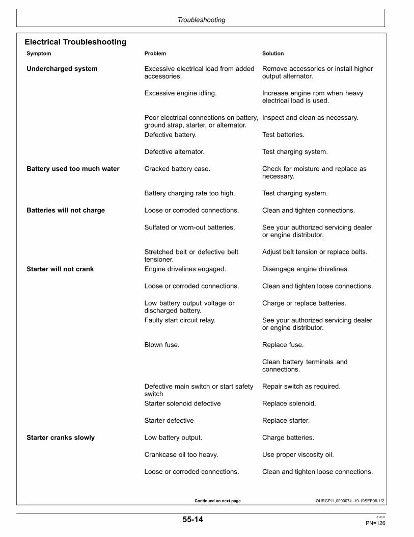
Troubleshooting
Continued on next page OURGP11,0000074 1919SEP061/2
Electrical TroubleshootingSymptom Problem Solution
Undercharged system Excessive electrical load from addedaccessories.
Remove accessories or install higheroutput alternator.
Excessive engine idling. Increase engine rpm when heavyelectrical load is used.
Poor electrical connections on battery,ground strap, starter, or alternator.
Inspect and clean as necessary.
Defective battery. Test batteries.
Defective alternator. Test charging system.
Battery used too much water Cracked battery case. Check for moisture and replace asnecessary.
Battery charging rate too high. Test charging system.
Batteries will not charge Loose or corroded connections. Clean and tighten connections.
Sulfated or wornout batteries. See your authorized servicing dealeror engine distributor.
Stretched belt or defective belttensioner.
Adjust belt tension or replace belts.
Starter will not crank Engine drivelines engaged. Disengage engine drivelines.
Loose or corroded connections. Clean and tighten loose connections.
Low battery output voltage ordischarged battery.
Charge or replace batteries.
Faulty start circuit relay. See your authorized servicing dealeror engine distributor.
Blown fuse. Replace fuse.
Clean battery terminals andconnections.
Defective main switch or start safetyswitch
Repair switch as required.
Starter solenoid defective Replace solenoid.
Starter defective Replace starter.
Starter cranks slowly Low battery output. Charge batteries.
Crankcase oil too heavy. Use proper viscosity oil.
Loose or corroded connections. Clean and tighten loose connections.
5514 010311
PN=126

Troubleshooting
OURGP11,0000074 1919SEP062/2
Symptom Problem Solution
Starter and hour meter functions;rest of electrical system does notfunction
Blown fuse on magnetic switch. Replace fuse.
Entire electrical system does notfunction
Faulty battery connection. Clean and tighten connections.
Sulfated or wornout batteries. Replace batteries.
Blown fuse. Replace fuse.
5515 010311
PN=127

Troubleshooting
Continued on next page OURGP11,0000075 1910NOV101/3
Lubrication System TroubleshootingSymptom Problem Solution
Low Oil Pressure Low crankcase oil level Fill crankcase to proper oil level.
Crankcase oil level too high Fill crankcase to proper oil level.
Faulty pressure sensor Replace sensor. See your John Deereengine distributor or servicing dealer.
Clogged oil cooler or filter Remove and inspect oil cooler. Seeyour John Deere engine distributor orservicing dealer.
Excessive oil temperature Remove and inspect oil cooler. Seeyour John Deere engine distributor orservicing dealer.
Defective oil pump Remove and inspect oil pump. Seeyour John Deere engine distributor orservicing dealer.
Incorrect oil Drain crankcase and refill with correctoil.
Oil pressure regulating valve failure Remove and inspect oil pressureregulating valve. See your John Deereengine distributor or servicing dealer.
Broken piston spray nozzle Replace piston spray nozzle. Seeyour John Deere engine distributor orservicing dealer.
Clogged oil pump screen or crackedpickup tube
Remove oil pan and cleanscreen/replace pickup tube.
Excessive main or connecting rodbearing clearance
Determine bearing clearance. Seeyour John Deere engine distributor orservicing dealer.
High Oil Pressure Improper oil classification Drain crankcase and refill with correctoil.
Faulty pressure sensor Replace sensor. See your John Deereengine distributor or servicing dealer.
Oil pressure regulating valve bushingloose (wanders)
Remove and inspect oil pressureregulating valve. See your John Deereengine distributor or servicing dealer.
Improperly operating regulating valve Remove and inspect oil pressureregulating valve. See your John Deereengine distributor or servicing dealer.
5516 010311
PN=128
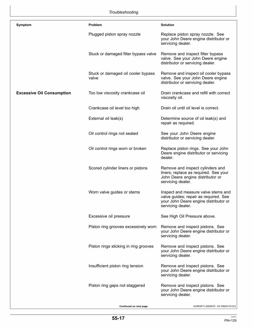
Troubleshooting
Continued on next page OURGP11,0000075 1910NOV102/3
Symptom Problem Solution
Plugged piston spray nozzle Replace piston spray nozzle. Seeyour John Deere engine distributor orservicing dealer.
Stuck or damaged filter bypass valve Remove and inspect filter bypassvalve. See your John Deere enginedistributor or servicing dealer.
Stuck or damaged oil cooler bypassvalve
Remove and inspect oil cooler bypassvalve. See your John Deere enginedistributor or servicing dealer.
Excessive Oil Consumption Too low viscosity crankcase oil Drain crankcase and refill with correctviscosity oil.
Crankcase oil level too high Drain oil until oil level is correct.
External oil leak(s) Determine source of oil leak(s) andrepair as required.
Oil control rings not seated See your John Deere enginedistributor or servicing dealer.
Oil control rings worn or broken Replace piston rings. See your JohnDeere engine distributor or servicingdealer.
Scored cylinder liners or pistons Remove and inspect cylinders andliners; replace as required. See yourJohn Deere engine distributor orservicing dealer.
Worn valve guides or stems Inspect and measure valve stems andvalve guides; repair as required. Seeyour John Deere engine distributor orservicing dealer.
Excessive oil pressure See High Oil Pressure above.
Piston ring grooves excessively worn Remove and inspect pistons. Seeyour John Deere engine distributor orservicing dealer.
Piston rings sticking in ring grooves Remove and inspect pistons. Seeyour John Deere engine distributor orservicing dealer.
Insufficient piston ring tension Remove and inspect pistons. Seeyour John Deere engine distributor orservicing dealer.
Piston ring gaps not staggered Remove and inspect pistons. Seeyour John Deere engine distributor orservicing dealer.
5517 010311
PN=129

Troubleshooting
OURGP11,0000075 1910NOV103/3
Symptom Problem Solution
Front and/or rear crankshaft oil sealfaulty
Replace oil seals. See your JohnDeere engine distributor or servicingdealer.
See LOW PRESSURE FUELSYSTEM TROUBLESHOOTING laterin this section.
Fuel in Oil See LOW PRESSURE FUELSYSTEM TROUBLESHOOTING laterin this section.
Coolant in Oil See COOLING SYSTEMTROUBLESHOOTING later inthis section.
5518 010311
PN=130
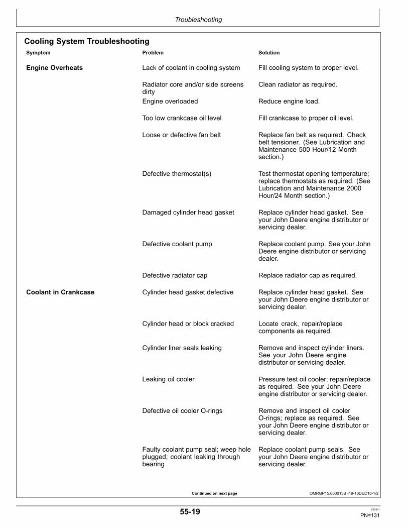
Troubleshooting
Continued on next page OMRGP15,000013B 1910DEC101/2
Cooling System TroubleshootingSymptom Problem Solution
Engine Overheats Lack of coolant in cooling system Fill cooling system to proper level.
Radiator core and/or side screensdirty
Clean radiator as required.
Engine overloaded Reduce engine load.
Too low crankcase oil level Fill crankcase to proper oil level.
Loose or defective fan belt Replace fan belt as required. Checkbelt tensioner. (See Lubrication andMaintenance 500 Hour/12 Monthsection.)
Defective thermostat(s) Test thermostat opening temperature;replace thermostats as required. (SeeLubrication and Maintenance 2000Hour/24 Month section.)
Damaged cylinder head gasket Replace cylinder head gasket. Seeyour John Deere engine distributor orservicing dealer.
Defective coolant pump Replace coolant pump. See your JohnDeere engine distributor or servicingdealer.
Defective radiator cap Replace radiator cap as required.
Coolant in Crankcase Cylinder head gasket defective Replace cylinder head gasket. Seeyour John Deere engine distributor orservicing dealer.
Cylinder head or block cracked Locate crack, repair/replacecomponents as required.
Cylinder liner seals leaking Remove and inspect cylinder liners.See your John Deere enginedistributor or servicing dealer.
Leaking oil cooler Pressure test oil cooler; repair/replaceas required. See your John Deereengine distributor or servicing dealer.
Defective oil cooler Orings Remove and inspect oil coolerOrings; replace as required. Seeyour John Deere engine distributor orservicing dealer.
Faulty coolant pump seal; weep holeplugged; coolant leaking throughbearing
Replace coolant pump seals. Seeyour John Deere engine distributor orservicing dealer.
5519 010311
PN=131

Troubleshooting
OMRGP15,000013B 1910DEC102/2
Symptom Problem Solution
Faulty injector sleeve Oring and EUIOrings faulty
Remove suspected EUI; replaceOrings as required. See your JohnDeere engine distributor or servicingdealer.
Coolant Temperature Below Normal Defective thermostat(s) Test thermostats; replace thermostatsas required. (See Service as Requiredsection.)
5520 010311
PN=132

Troubleshooting
Continued on next page OURGP11,000005F 1910NOV101/3
Air Intake and Exhaust SystemTroubleshootingIf turbocharger requires replacement, determine whatcaused the failure of the defective unit, and correct the
condition. This will prevent an immediate repeat failure ofthe replacement unit.
Symptom Problem Solution
Hard to Start or Will Not Start See ENGINE TROUBLESHOOTING earlier in this section.
Engine Misfiring or Runs Irregularly See ENGINE TROUBLESHOOTING earlier in this section.
Black or Grey Exhaust Smoke See ENGINE TROUBLESHOOTING earlier in this section.
Lack of Engine Power See ENGINE TROUBLESHOOTING earlier in this section.
Turbocharger “Screams” Air leak in intake manifold. Check intake manifold gasket andmanifold; repair as required. Seeyour John Deere engine distributor orservicing dealer.
Turbocharger Noise or Vibration
NOTE: Variable geometryturbocharger recycles afterstarting engine, causing amomentary revving sound in theengine. This is normal.
Do not confuse the whine heardduring run down with noisewhich indicates a bearing failure.
Bearings not lubricated (insufficient oilpressure)
Determine cause of lack of lubrication;repair as required. See your JohnDeere engine distributor or servicingdealer.
Air leak in engine intake or exhaustmanifold
Check intake and exhaust manifoldgaskets and manifolds; repair asrequired. See your John Deere enginedistributor or servicing dealer.
Improper clearance between turbinewheel and turbine housing
Inspect turbocharger; repair/replaceas required. See your John Deereengine distributor or servicing dealer.
Broken blades (or other wheel failures) Inspect turbocharger; repair/replaceas required. See your John Deereengine distributor or servicing dealer.
Oil on Turbocharger CompressorWheel or in Compressor Housing(Oil Being Pushed or Pulledthrough Center Housing)
Excessive crankcase pressure. Determine cause of excessivecrankcase pressure; repair asrequired. See your John Deere enginedistributor or servicing dealer.
Air intake restriction Determine cause of intake restriction;repair as required. See your JohnDeere engine distributor or servicingdealer.
5521 010311
PN=133
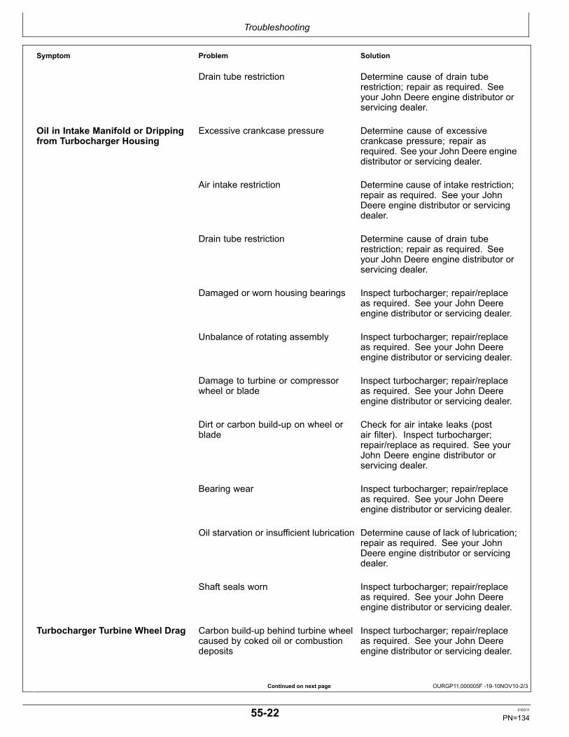
Troubleshooting
Continued on next page OURGP11,000005F 1910NOV102/3
Symptom Problem Solution
Drain tube restriction Determine cause of drain tuberestriction; repair as required. Seeyour John Deere engine distributor orservicing dealer.
Oil in Intake Manifold or Drippingfrom Turbocharger Housing
Excessive crankcase pressure Determine cause of excessivecrankcase pressure; repair asrequired. See your John Deere enginedistributor or servicing dealer.
Air intake restriction Determine cause of intake restriction;repair as required. See your JohnDeere engine distributor or servicingdealer.
Drain tube restriction Determine cause of drain tuberestriction; repair as required. Seeyour John Deere engine distributor orservicing dealer.
Damaged or worn housing bearings Inspect turbocharger; repair/replaceas required. See your John Deereengine distributor or servicing dealer.
Unbalance of rotating assembly Inspect turbocharger; repair/replaceas required. See your John Deereengine distributor or servicing dealer.
Damage to turbine or compressorwheel or blade
Inspect turbocharger; repair/replaceas required. See your John Deereengine distributor or servicing dealer.
Dirt or carbon buildup on wheel orblade
Check for air intake leaks (postair filter). Inspect turbocharger;repair/replace as required. See yourJohn Deere engine distributor orservicing dealer.
Bearing wear Inspect turbocharger; repair/replaceas required. See your John Deereengine distributor or servicing dealer.
Oil starvation or insufficient lubrication Determine cause of lack of lubrication;repair as required. See your JohnDeere engine distributor or servicingdealer.
Shaft seals worn Inspect turbocharger; repair/replaceas required. See your John Deereengine distributor or servicing dealer.
Turbocharger Turbine Wheel Drag Carbon buildup behind turbine wheelcaused by coked oil or combustiondeposits
Inspect turbocharger; repair/replaceas required. See your John Deereengine distributor or servicing dealer.
5522 010311
PN=134

Troubleshooting
OURGP11,000005F 1910NOV103/3
RG,RG34710,7605 1912SEP061/1
Symptom Problem Solution
Dirt buildup behind compressor wheelcaused by air intake leaks
Inspect turbocharger; repair/replaceas required. See your John Deereengine distributor or servicing dealer.
Bearing seizure or dirty, worn bearings Inspect turbocharger; repair/replaceas required. See your John Deereengine distributor or servicing dealer.
Low Pressure Fuel System TroubleshootingSymptom Problem Solution
Fuel in Oil Cracked or worn electronic unitinjector (EUI) Oring
Remove suspected EUI; replace EUIOring as required. See your JohnDeere engine distributor or servicingdealer.
Cracked cylinder head Locate crack; repair/replacecomponents as required. See yourJohn Deere engine distributor orservicing dealer.
Fuel Aeration EUI holddown clamp loose Tighten holddown clamp cap screw toproper torque. See your John Deereengine distributor or servicing dealer.
Cracked or worn electronic unitinjector (EUI) Oring
Remove suspected EUI; replace EUIOring as required. See your JohnDeere engine distributor or servicingdealer.
Fuel Pressure Low Plugged fuel filter Replace fuel filter.
Restricted fuel line Locate restriction; repair as required.
Faulty fuel transfer pump Remove fuel transfer pump;repair/replace pump as required. Seeyour John Deere engine distributor orservicing dealer.
5523 010311
PN=135

Troubleshooting
OMRGP15,0000136 1912SEP061/1
Electrical System Layout
RG14343—UN—12AUG05
Electrical System Layout Left Side
5524 010311
PN=136

Troubleshooting
OURGP11,0000079 1925SEP061/1
Electrical System Layout Continued
RG14344—UN—05AUG05
Electrical System Layout Right Side
A—Turbocharger Air InletTemperature Sensor Lead
B—Turbocharger ActuatorConnector Lead
C—Turbocharger Speed SensorLead
D—Alternator ConnectorE—Manifold Air Pressure (MAP)
Sensor
F—EGR Temperature SensorG—Engine Position (Cam) SensorH—Rear EGR Valve ConnectorI— Timing (Crank) SensorJ—Auxiliary Connector
K—Engine Control Unit (ECU)Connectors
L—Unit Injection ConnectorM—Fuel Temperature SensorN—WaterInFuel SensorO—Oil Pressure Sensor
P—Fuel Pressure SensorQ—Coolant Temperature SensorR—Exhaust Air Temperature
SensorS—Manifold Inlet Air Sensor
5525 010311
PN=137
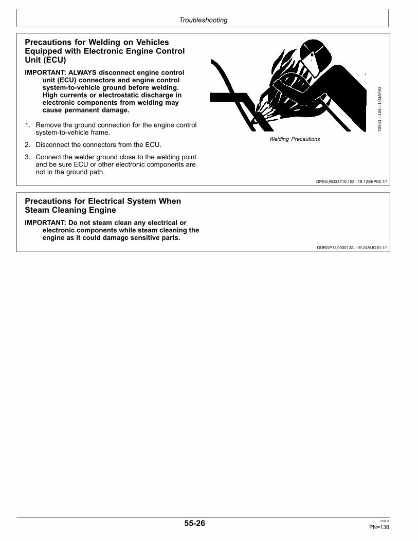
Troubleshooting
DPSG,RG34710,102 1912SEP061/1
OURGP11,000012A 1924AUG101/1
Precautions for Welding on VehiclesEquipped with Electronic Engine ControlUnit (ECU)IMPORTANT: ALWAYS disconnect engine control
unit (ECU) connectors and engine controlsystemtovehicle ground before welding.High currents or electrostatic discharge inelectronic components from welding maycause permanent damage.
1. Remove the ground connection for the engine controlsystemtovehicle frame.
2. Disconnect the connectors from the ECU.
3. Connect the welder ground close to the welding pointand be sure ECU or other electronic components arenot in the ground path.
TS953—UN—15MAY
90
Welding Precautions
Precautions for Electrical System WhenSteam Cleaning EngineIMPORTANT: Do not steam clean any electrical or
electronic components while steam cleaning theengine as it could damage sensitive parts.
5526 010311
PN=138

Troubleshooting
OURGP12,00000EC 1912SEP061/1
Engine Wiring Diagram (Engines With FullFeatured Instrument Panel)
RG13874—UN—08APR05
B1—Analog ThrottleC06— Alternator Harness
ConnectorC12— Transient Voltage
ProtectorC13— Starter RelayC14— Starter RelayC15— Remote On/OffC16— Battery
C17— Single Point GroundF01— Fuse (30 Amp)(System)F02— Fuse (20 Amp)(ECU)F03— Fuse (15 Amp)(Fuel Filter)G1—AlternatorM1—Starter MotorP1—Optional Gauge
P2—Optional GaugeP3—Oil Pressure GaugeP4—Coolant Temperature GaugeP5—Tachometer DisplayP6—Hour Meter/Diagnostic
GaugeS1—Ignition Key SwitchS2—Speed Select Switch
(Momentary)
S3—Bump Enable Switch(Momentary)
S4—HighLow Speed SelectSwitch
S5—Override Shutdown Switch(Momentary)
V1—DiodeX1—Vehicle Harness ConnectorX4—CAN TerminatorX5—Analog Throttle Connector
5527 010311
PN=139

Troubleshooting
OURGP11,0000071 1919SEP061/1
Engine Wiring Diagram (Engines With FullFeatured Instrument Panel) (Continued)
RG14936—UN—19SEP06
B1—Analog Throttle EmulatorF1— Fuse (10 Amp)F2—Fuse (5 Amp)S1—Ignition Key Switch
S2—Speed Select Switch(Momentary)
S3—Bump Enable Switch(Momentary
S4—Dual State Throttle SwitchS5—Override Shutdown Switch
(Momentary)
S7—Tristate Throttle SwitchS8—Ramp Throttle SwitchX3—Single Point GroundX5—Analog Throttle Connector
X6—Remote On/Off Plug
5528 010311
PN=140

Troubleshooting
OURGP11,0000072 1925SEP061/1
Engine Wiring Diagram (Engines With FullFeatured Instrument Panel) (Continued)
RG10040A
—19—13NOV01
E1—Back Light Regulator (24V)or Plug (12V)
F2— Fuse (5 Amp)N2—Voltage Regulator (for 24V
Operation)
P1—Optional GaugeP2—Optional GaugeP3—Oil Pressure Gauge
P4—Coolant Temperature GaugeP5—Tachometer DisplayP6—Hourmeter/Diagnostic Meter
S5—Override Shutdown Switch(Momentary)
S6—Dimmer Control or JumperPlug
X4—CAN Terminator
5529 010311
PN=141

Storage
OURGP12,00000DF 1911OCT061/1
OURGP11,0000060 1912SEP061/1
Engine Storage Guidelines
1. John Deere engines can be stored outside for upto three (3) months with no long term preparationIF COVERED BY WATERPROOF COVERING. Nooutside storage is recommended without a waterproofcovering.
2. John Deere engines can be stored in a standardoverseas shipping container for up to three (3) monthswith no long term preparation.
3. John Deere engines can be stored inside for up to six(6) months with no long term preparation.
4. John Deere engines expected to be stored morethan six (6) months MUST have long term storagepreparation. ( See PREPARING ENGINE FOR LONGTERM STORAGE, later in this section.)
5. Long term storage includes the use of a stabilized rustpreventive oil to protect internal metal componentsof the engine. This oil should be an SAE 10 oil with14 percent morpholine or equivalent vapor corrosioninhibitor. These rust preventive oils are available fromarea distributors.
Preparing Engine for Long Term Storage
The following storage preparations are used for long termengine storage up to one year. After that, the engineshould be started, warmed up, and retreated for anextended storage period.
IMPORTANT: Any time your engine will not beused for over six (6) months, the followingrecommendations for storing it and removingit from storage will help to minimizecorrosion and deterioration.
1. Change engine oil and replace filter. (See CHANGEENGINE OIL AND FILTER in Lubrication andMaintenance/500 Hour Section.) Used oil will notgive adequate protection. Add one (1) ounce of rustpreventive oil to the engine crankcase for every quartof oil. This rust preventive oil should be an SAE 10oil with 14 percent morpholine or equivalent vaporcorrosion inhibitor.
2. Service air cleaner. (See REPLACING AIR CLEANERFILTER ELEMENTS in Service As Required Section.)
3. Draining and flushing of cooling system is notnecessary if engine is to be stored only for severalmonths. However, for extended storage periods ofa year or longer, it is recommended that the coolingsystem be drained, flushed, and refilled. Refill withappropriate coolant. (See RECOMMENDED ENGINECOOLANT in Fuels, Lubricants, and Coolant Sectionand ADDING COOLANT in Service As RequiredSection.)
4. Pour three (3) ounces of rust preventive oil intothe turbocharger intake. (It may be necessaryto temporarily install a short intake elbow on theturbocharger inlet to receive the oil.)
5. Prepare a tank with a solution of diesel fuel and rustpreventive oil, at ten (10) ounces of rust preventive oilper gallon of diesel fuel.
6. Remove existing lines/plugs as required, and run atemporary line from the tank to the engine fuel intake,and another temporary line from the fuel return tothe tank, so rust preventive oil solution is circulatedthrough the injection system during cranking.
7. Crank the engine several revolutions with starter (donot allow the engine to start). This will allow rustpreventive oil solution to circulate.
8. Remove temporary lines installed in Step 6 above,and replace any lines/plugs previously removed.
NOTE: One gallon of fuel/oil solution can be used totreat 100 engines; two gallons to treat 200 engines,etc. The oil could then be replenished by addingan additional five (5) ounces of rust preventiveoil per gallon of solution. However, starting overwith a new solution is recommended to disposeof any water or other impurities.
9. Loosen, or remove and store, fan/alternator polyveebelt.
10. Remove and clean batteries. Store them in a cool, dryplace and keep them fully charged.
11. Disengage the clutch for any driveline.
12. Clean the exterior of the engine with saltfree waterand touch up any scratched or chipped paintedsurfaces with a good quality paint.
13. Coat all exposed (machined) metal surfaces withgrease or corrosion inhibitor if not feasible to paint.
14. Seal all openings on engine with plastic bags and tape.
15. Store the engine in a dry protected place. If enginemust be stored outside, cover it with a waterproofcanvas or other suitable protective material and usea strong waterproof tape.
601 010311
PN=142

Storage
RG,RG34710,4094 1912SEP061/1
Removing Engine from LongTerm Storage
Refer to the appropriate section for detailed serviceslisted below or have your authorized servicing dealer orengine distributor perform services that you may not befamiliar with.
1. Remove all protective coverings from engine. Unsealall openings in engine and remove covering fromelectrical systems.
2. Remove the batteries from storage. Install batteries(fully charged) and connect the terminals.
3. Install fan/alternator belts if removed.
4. Fill fuel tank.
5. Perform all appropriate prestarting checks. (SeeDAILY PRESTARTING CHECKS in Engine OperatingGuidelines Section.)
IMPORTANT: DO NOT operate starter more than 30seconds at a time. Wait at least 2 minutes forstarter to cool before trying again.
6. Crank engine for 20 seconds with starter (do not allowthe engine to start). Wait 2 minutes and crank enginean additional 20 seconds to assure bearing surfacesare adequately lubricated.
7. Start engine and run at low idle and no load for severalminutes. Warm up carefully and check all gaugesbefore placing engine under load.
8. On the first day of operation after storage, checkoverall engine for leaks and check all gauges forcorrect operation.
602 010311
PN=143

Specifications
Continued on next page OMRGP15,0000141 1910DEC101/2
General OEM Engine Specifications
ITEM 6135HF485 (13.5L)Number of Cylinders 6Bore 132 mm
(5.2 in.)Stroke 165 mm
(6.5 in.)Displacement 13.5 L
(824 cu in.)Compression Ratio 17.5:1 (Low Power Engines)
16.0:1 (High Power Engines)Aspiration TurbochargedEngine Firing Order 153624Valves Per Cylinder 2 Intake
2 ExhaustBattery12Volt System Capacity12Volt System Reserve24Volt System Capacity24Volt System Reserve
1900 CCA250 Minutes925 CCA275 CCA
Thermostat Start To Open Temperature 80°C(176°F)
Thermostat Fully Open Temperature 92°C(197°F)
Coolant Capacitya 18 L(19 qt)
Recommended Radiator Pressure Cap 103 kPa(15 psi)
Crankcase Oil Fill Capacity See “Engine Crankcase Oil Fill Quantities” later in this section.Oil Pressure At Rated Speed With Oil Warmed to 105°C (220°F) 310 kPa
(3.1 bar)(45 psi)
Oil Pressure At Low Idle (Minimum) 138 kPa(1.4 bar)(20 psi)
Length 1334 mm(52.5 in.)
Width 775 mm(30.5 in.)
Height 1350 mm(53.1 in.)
Weight (dry) 3292 kg(1493 lb)
ITEM 6090HF475 (13.5L)Number of Cylinders 6Bore 132 mm
(5.2 in.)Stroke 165 mm
(6.5 in.)Displacement 13.5 L
(824 cu in.)Compression Ratio 16.0:1Aspiration TurbochargedEngine Firing Order 153624Valves Per Cylinder 2 Intake
2 ExhaustBattery12Volt System Capacity12Volt System Reserve24Volt System Capacity24Volt System Reserve
1900 CCA250 Minutes925 CCA275 CCA
651 010311
PN=144
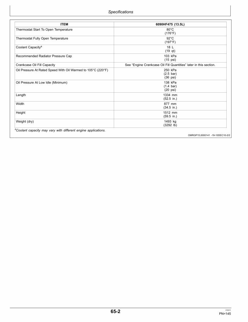
Specifications
OMRGP15,0000141 1910DEC102/2
ITEM 6090HF475 (13.5L)Thermostat Start To Open Temperature 80°C
(176°F)Thermostat Fully Open Temperature 92°C
(197°F)Coolant Capacitya 18 L
(19 qt)Recommended Radiator Pressure Cap 103 kPa
(15 psi)Crankcase Oil Fill Capacity See “Engine Crankcase Oil Fill Quantities” later in this section.Oil Pressure At Rated Speed With Oil Warmed to 105°C (220°F) 250 kPa
(2.5 bar)(36 psi)
Oil Pressure At Low Idle (Minimum) 138 kPa(1.4 bar)(20 psi)
Length 1334 mm(52.5 in.)
Width 877 mm(34.5 in.)
Height 1512 mm(59.5 in.)
Weight (dry) 1493 kg(3292 lb)
aCoolant capacity may vary with different engine applications.
652 010311
PN=145

Specifications
Continued on next page JR74534,00002D8 1927SEP101/2
Engine Power Ratings1 And Fuel SystemSpecifications2For Mechanical Fuel PrimerSystem (Earlier Engines)Engine Model Fuel System
Option CodesElectronic SoftwareOption Codes
SystemVoltage
Power Rating@ RatedSpeedkW (hp)
Rated Speed(rpm)
Slow Idle (rpm) Fast Idle(rpm)
6135HF485Industrial
1669 7219 12V 448 (600) 2100 900 2300
1669 7220 24V 448 (600) 2100 900 23001669 7221 12V 410 (550) 2100 900 23001669 7222 24V 410 (550) 2100 900 23001669 7223 12V 410 (550) a 2100 900 23001669 7224 24V 410 (550) a 2100 900 23001669 7225 12V 392 (525) a 2100 900 23001669 7226 24V 392 (525) a 2100 900 23001669 7227 12V 373 (500) 2100 900 23001669 7228 24V 373 (500) 2100 900 23001669 7229 12V 373 (500) a 2100 900 23001669 7230 24V 373 (500) a 2100 900 23001669 7231 12V 373 (500) a 1900 900 21001669 7232 24V 373 (500) a 1900 900 21001669 7233 12V 336 (450) 2100 900 23001669 7234 24V 336 (450) 2100 900 23001669 7235 12V 336 (450) a 2100 900 23001669 7236 24V 336 (450) a 2100 900 23001669 7237 12V 336 (450) a 1900 900 21001669 7238 24V 336 (450) a 1900 900 21001669 7239 12V 317 (425) a 2100 900 23001669 7240 24V 317 (425) a 2100 900 23001669 7241 12V 298 (400) 2100 900 23001669 7242 24V 298 (400) 2100 900 23001669 7243 12V 298 (400) a 2100 900 23001669 7244 24V 298 (400) a 2100 900 23001669 7245 12V 298 (400) a 1900 900 21001669 7246 24V 298 (400) a 1900 900 21001669 7247 12V 261 (350) 2100 900 23001669 7248 24V 261 (350) 2100 900 23001669 7249 12V 261 (350) a 2100 900 23001669 7250 24V 261 (350) a 2100 900 23001669 7251 12V 261 (350) a 1900 900 21001669 7252 24V 261 (350) a 1900 900 2100
6135HF485GenSet
1669 7253 12V 401 (538) 1800 900 1850
1669 7254 24V 401 (538) 1800 900 18501669 7255 12V 460 (617) 1800 900 18501669 7256 24V 460 (617) 1800 900 18501669 7266 12V 345 (463) 1800 900 18501669 7267 24V 345 (463) 1800 900 1850
6135HF475GenSet
1676 7268 12V 475 (354) 1500 1000 N/A
1676 7269 24V 475 (354) 1500 1000 N/A1676 7270 12V 543 (405) 1500 1000 N/A
653 010311
PN=146

Specifications
JR74534,00002D8 1927SEP102/2
OMRGP15,0000144 1909DEC101/1
Engine Model Fuel SystemOption Codes
Electronic SoftwareOption Codes
SystemVoltage
Power Rating@ RatedSpeedkW (hp)
Rated Speed(rpm)
Slow Idle (rpm) Fast Idle(rpm)
1676 7271 24V 543 (405) 1500 1000 N/A1676 7272 12V 611 (456) 1500 1000 N/A1676 7273 24V 611 (456) 1500 1000 N/A1676 72DA 12V 443 (330) 1800 1000 N/A1676 72DB 24V 443 (330) 1800 1000 N/A1676 72DC 12V 483 (360) 1800 1000 N/A1676 72DD 24V 483 (360) 1800 1000 N/A1676 72DE 12V 563 (420) 1800 1000 N/A1676 72DF 24V 563 (420) 1800 1000 N/A1676 72DG 12V 617 (460) 1800 1000 N/A1676 72DH 24V 617 (460) 1800 1000 N/A
a These industrial engines have a power bulge which allows for INTERMITTENT operation above rated power.1Power ratings are for bare engines without drag effect of coolingfan or accessories like air compressors.2Engine speeds listed are preset to factory specification. Slow idlespeed may be reset depending upon specific vehicle applicationrequirements. Refer to your machine operator’s manual for enginespeeds that are different from those preset at the factory.
Engine Crankcase Oil Fill Quantities
RG14341—UN—26JU
L05
Option Code Label
To determine the crankcase oil fill quantity for your engine,refer to the oil pan option code (A) located on the engineoption code label affixed to the valve cover. The first twodigits of the code (19) identify the oil pan group. The lasttwo digits of each code identify the specific oil pan onyour engine.
Listed below are engine crankcase oil fill quantities withfilter change for each oil pan option code and PTOconfiguration:
Engine Model Oil Pan Option Codes Crankcase Oil Capacity a
6135HF (Without John Deere Rear PTO) 1915, 1917, 19181914
40.0 L (42.3 qt.)60.0 L (63.4 qt.)
a Crankcase oil capacity may vary slightly from amount shown. ALWAYS fill crankcase to within crosshatch area on dipstick. DO NOT overfill.
NOTE: If engine is equipped with John DeerePTO, add an additional 4 L (4.2 qt) of oil tolubricate PTO gear train.
654 010311
PN=147

Specifications
DX,TORQ1 1908DEC091/1
Unified Inch Bolt and Screw Torque ValuesTS1671 —UN—01MAY03
Bolt or SAE Grade 1 SAE Grade 2a SAE Grade 5, 5.1 or 5.2 SAE Grade 8 or 8.2Screw Lubricatedb Dryc Lubricatedb Dryc Lubricatedb Dryc Lubricatedb Dryc
Size N∙m lb.in. N∙m lb.in. N∙m lb.in. N∙m lb.in. N∙m lb.in. N∙m lb.in. N∙m lb.in. N∙m lb.in.1/4 3.7 33 4.7 42 6 53 7.5 66 9.5 84 12 106 13.5 120 17 150
N∙m lb.ft. N∙m lb.ft.5/16 7.7 68 9.8 86 12 106 15.5 137 19.5 172 25 221 28 20.5 35 26
N∙m lb.ft. N∙m lb.ft.3/8 13.5 120 17.5 155 22 194 27 240 35 26 44 32.5 49 36 63 46
N∙m lb.ft. N∙m lb.ft. N∙m lb.ft.7/16 22 194 28 20.5 35 26 44 32.5 56 41 70 52 80 59 100 74
N∙m lb.ft.1/2 34 25 42 31 53 39 67 49 85 63 110 80 120 88 155 1159/16 48 35.5 60 45 76 56 95 70 125 92 155 115 175 130 220 1655/8 67 49 85 63 105 77 135 100 170 125 215 160 240 175 305 2253/4 120 88 150 110 190 140 240 175 300 220 380 280 425 315 540 4007/8 190 140 240 175 190 140 240 175 490 360 615 455 690 510 870 6401 285 210 360 265 285 210 360 265 730 540 920 680 1030 760 1300 960
11/8 400 300 510 375 400 300 510 375 910 670 1150 850 1450 1075 1850 135011/4 570 420 725 535 570 420 725 535 1280 945 1630 1200 2050 1500 2600 192013/8 750 550 950 700 750 550 950 700 1700 1250 2140 1580 2700 2000 3400 250011/2 990 730 1250 930 990 730 1250 930 2250 1650 2850 2100 3600 2650 4550 3350
Torque values listed are for general use only, based on the strength of the boltor screw. DO NOT use these values if a different torque value or tighteningprocedure is given for a specific application. For plastic insert or crimped steeltype lock nuts, for stainless steel fasteners, or for nuts on Ubolts, see thetightening instructions for the specific application. Shear bolts are designed to failunder predetermined loads. Always replace shear bolts with identical grade.
Replace fasteners with the same or higher grade. If highergrade fasteners are used, tighten these to the strength of theoriginal. Make sure fastener threads are clean and that youproperly start thread engagement. When possible, lubricateplain or zinc plated fasteners other than lock nuts, wheel boltsor wheel nuts, unless different instructions are given for thespecific application.
aGrade 2 applies for hex cap screws (not hex bolts) up to 6. in (152 mm) long. Grade 1 applies for hex cap screws over 6in. (152 mm) long, and for all other types of bolts and screws of any length.b“Lubricated” means coated with a lubricant such as engine oil, fasteners with phosphate and oil coatings, or 7/8in. and larger fasteners with JDM F13C zinc flake coating.c“Dry” means plain or zinc plated without any lubrication, or 1/4 to 3/4 in. fasteners with JDM F13B zinc flake coating.
655 010311
PN=148

Specifications
DX,TORQ2 1908DEC091/1
Metric Bolt and Screw Torque ValuesTS1670 —UN—01MAY03
4.84.8 8.8 9.8 10.9 12.9 12.9
12.912.910.99.88.84.8
Bolt or Class 4.8 Class 8.8 or 9.8 Class 10.9 Class 12.9Screw Lubricateda Dryb Lubricateda Dryb Lubricateda Dryb Lubricateda Dryb
Size N∙m lb.in. N∙m lb.in. N∙m lb.in. N∙m lb.in. N∙m lb.in. N∙m lb.in. N∙m lb.in. N∙m lb.in.M6 4.7 42 6 53 8.9 79 11.3 100 13 115 16.5 146 15.5 137 19.5 172
N∙m lb.ft. N∙m lb.ft. N∙m lb.ft. N∙m lb.ft.M8 11.5 102 14.5 128 22 194 27.5 243 32 23.5 40 29.5 37 27.5 47 35
N∙m lb.ft. N∙m lb.ft. N∙m lb.ft.M10 23 204 29 21 43 32 55 40 63 46 80 59 75 55 95 70
N∙m lb.ft.M12 40 29.5 50 37 75 55 95 70 110 80 140 105 130 95 165 120M14 63 46 80 59 120 88 150 110 175 130 220 165 205 150 260 190M16 100 74 125 92 190 140 240 175 275 200 350 255 320 235 400 300M18 135 100 170 125 265 195 330 245 375 275 475 350 440 325 560 410M20 190 140 245 180 375 275 475 350 530 390 675 500 625 460 790 580M22 265 195 330 245 510 375 650 480 725 535 920 680 850 625 1080 800M24 330 245 425 315 650 480 820 600 920 680 1150 850 1080 800 1350 1000M27 490 360 625 460 950 700 1200 885 1350 1000 1700 1250 1580 1160 2000 1475M30 660 490 850 625 1290 950 1630 1200 1850 1350 2300 1700 2140 1580 2700 2000M33 900 665 1150 850 1750 1300 2200 1625 2500 1850 3150 2325 2900 2150 3700 2730M36 1150 850 1450 1075 2250 1650 2850 2100 3200 2350 4050 3000 3750 2770 4750 3500
Torque values listed are for general use only, based on the strength ofthe bolt or screw. DO NOT use these values if a different torque value ortightening procedure is given for a specific application. For stainless steelfasteners or for nuts on Ubolts, see the tightening instructions for thespecific application. Tighten plastic insert or crimped steel type lock nutsby turning the nut to the dry torque shown in the chart, unless differentinstructions are given for the specific application.
Shear bolts are designed to fail under predetermined loads. Alwaysreplace shear bolts with identical property class. Replace fasteners withthe same or higher property class. If higher property class fasteners areused, tighten these to the strength of the original. Make sure fastenerthreads are clean and that you properly start thread engagement. Whenpossible, lubricate plain or zinc plated fasteners other than lock nuts,wheel bolts or wheel nuts, unless different instructions are given for thespecific application.
a“Lubricated” means coated with a lubricant such as engine oil, fasteners with phosphate and oil coatings, or M20and larger fasteners with JDM F13C zinc flake coating.b“Dry” means plain or zinc plated without any lubrication, or M6 to M18 fasteners with JDM F13B zinc flake coating.
656 010311
PN=149

Lubrication and Maintenance Records
RG,RG34710,7621 1912SEP061/1
RG,RG34710,7622 1930SEP101/1
OURGP11,0000066 1915OCT101/1
Using Lubrication and Maintenance RecordsRefer to specific Lubrication and Maintenance section fordetailed service procedures.
1. Keep a record of the number of hours you operateyour engine by regular observation of hour meter.
2. Check your record regularly to learn when your engineneeds service.
3. DO ALL the services within an interval section. Writethe number of hours (from your service records) and
the date in the spaces provided. For a complete listingof all items to be performed and the service intervalsrequired, refer to the quickreference chart near thefront of the Lubrication and Maintenance section.
IMPORTANT: The service recommendations coveredin this manual are for the accessories that areprovided by John Deere. Follow manufacturer’sservice recommendations for servicingenginedriven equipment not supplied by Deere.
Daily (Prestarting) ServiceNOTE: Refer to DAILY PRESTARTING CHECKS in
Lubrication and Maintenance/Daily section.
• Check engine oil level.
• Check coolant level.• Check fuel filter/water separator.• Check air cleaner dust unloader valve and air restrictionindicator, if equipped.• Visual walkaround inspection.
500 Hours of Operation/or 12 Months Service
• Service fire extinguisher.• Service battery.• Change engine oil and oil filter.12• Check coolant pump weep hole.• Replace fuel filters.• Check and adjust engine speeds.• Check engine mounts.
• Clean crankcase vent hose and valve.• Check air intake hoses, connections, and system.• Check engine ground connection.• Check automatic belt tensioner and belt wear.• Check cooling system.• Coolant solution analysis—add SCAs as needed.• Pressure test overall cooling system and radiator cap.
HoursDateHoursDateHoursDateHoursDateHoursDateHoursDateHoursDate
1During engine breakin, change the oil and filter for the first time aftera minumum of 100 hours of operation (500 hours maximum).2 Service intervals depend on sulfur content of the diesel fuel, oil pancapacity, and the oil and filter used. (See DIESEL ENGINE OIL ANDFILTERSERVICE INTERVALS, in Fuels, Lubricants, andCoolant Section.)
701 010311
PN=150

Lubrication and Maintenance Records
OURGP11,0000067 1930SEP101/1
RG,RG34710,7626 1930SEP101/1
OURGP11,0000125 1912SEP061/1
2000 Hours of Operation/or 24 MonthsService• Check crankshaft vibration damper.
• Flush and refill cooling system.1• Test thermostats.
HoursDateHoursDateHoursDateHoursDateHoursDate
1 When John Deere COOLGARD is used, the flushing interval is3000 hours or 36 months. The drain interval may be extended to5000 hours or 60 months of operation provided that the coolantis tested annually AND additives are replenished, as needed,by adding a supplemental coolant additive.
2500 Hours of Operation Service• Have your authorized servicing dealer or enginedistributor check and adjust valve clearance and
electronic unit injector (EUI) preload. (This is a onetimeservice on a new or overhauled engine.)
HoursDateHoursDateHoursDateHoursDate
Service as Required• Add coolant.• Replace air cleaner filter elements.• Clean fuel filter water separator bowl.• Bleed fuel system.
• Replace fan/alternator Vbelts.• Check fuses.• Service air compressor. (See your John Deere dealer.)• Service rear PTO (See your John Deere dealer.)
HoursDateHoursDateHoursDateHoursDate
702 010311
PN=151

Emission System Warranty
OURGP11,0000069 1911OCT061/1
OURGP11,0000068 1912SEP061/1
U.S. EPA Emissions Control Warranty Statement
Emissions controlrelated parts and components arewarranted by John Deere for five years or 3000 hoursof operation, whichever occurs first. John Deere furtherwarrants that the engine covered by this warranty wasdesigned, built, and equipped so as to conform at thetime of sale with all U.S. emissions standards at the timeof manufacture, and that it is free of defects in materialsand workmanship which would cause it not to meet these
standards within the period of five years or 3000 hours ofoperation, whichever occurs first.
Warranties stated in this manual refer only toemissionsrelated parts and components of your engine.The complete engine warranty, less emissionsrelatedparts and components, is provided separately as the“John Deere New OffHighway Engine Warranty”.
Emissions Control System CertificationLabel
CAUTION: Statutes providing severe penaltiesfor tampering with emissions controls mayapply to the user or dealer.
The emissions warranty described above applies only tothose engines marketed by John Deere that have beencertified by the United States Environmental ProtectionAgency (EPA) and/or California Air Resources Board(CARB), and used in the United States and Canada.The presence of an emissions label like the one shownsignifies that the engine has been certified with the EPAand/or CARB. The EPA and CARB warranties only applyto new engines having the certification label affixed to theengine and sold as stated above in the geographic areas.The presence of an EU number in the third line of thelabel signifies that the engine has been certified with theEuropean Union countries per Directive 97/68/EC. Theemissions warranty does not apply to the EU countries.
RG14939—UN—11OCT06
Emissions Label
NOTE: The hp/kW rating on the engine emissionscertification label specifies the gross engine hp/kW,which is flywheel power without fan. In mostapplications this will not be the same rating asthe advertised vehicle hp/kW rating.
751 010311
PN=152
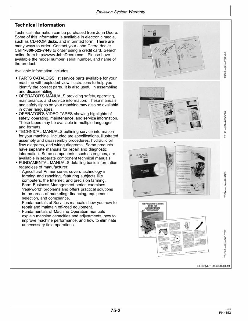
Emission System Warranty
DX,SERVLIT 1931JUL031/1
Technical InformationTechnical information can be purchased from John Deere.Some of this information is available in electronic media,such as CDROM disks, and in printed form. There aremany ways to order. Contact your John Deere dealer.Call 18005227448 to order using a credit card. Searchonline from http://www.JohnDeere.com. Please haveavailable the model number, serial number, and name ofthe product.
Available information includes:
• PARTS CATALOGS list service parts available for yourmachine with exploded view illustrations to help youidentify the correct parts. It is also useful in assemblingand disassembling.• OPERATOR’S MANUALS providing safety, operating,maintenance, and service information. These manualsand safety signs on your machine may also be availablein other languages.• OPERATOR’S VIDEO TAPES showing highlights ofsafety, operating, maintenance, and service information.These tapes may be available in multiple languagesand formats.• TECHNICAL MANUALS outlining service informationfor your machine. Included are specifications, illustratedassembly and disassembly procedures, hydraulic oilflow diagrams, and wiring diagrams. Some productshave separate manuals for repair and diagnosticinformation. Some components, such as engines, areavailable in separate component technical manuals• FUNDAMENTAL MANUALS detailing basic informationregardless of manufacturer: Agricultural Primer series covers technology infarming and ranching, featuring subjects likecomputers, the Internet, and precision farming.
Farm Business Management series examines“realworld” problems and offers practical solutionsin the areas of marketing, financing, equipmentselection, and compliance.
Fundamentals of Services manuals show you how torepair and maintain offroad equipment.
Fundamentals of Machine Operation manualsexplain machine capacities and adjustments, how toimprove machine performance, and how to eliminateunnecessary field operations.
TS189—UN—17JAN89
TS191—UN—02DEC88
TS224—UN—17JAN89
TS1663
—UN—10OCT97
752 010311
PN=153

Emission System Warranty
753 010311
PN=154

Index
Page
A
Acid burns................................................................... 351Additional Service Information.................................... 501Air cleaner, replace elements ..................................... 502Air compressor ........................................................... 506Air intake systemCheck.................................................................... 3512Troubleshooting .................................................... 5521
Auxiliary gear drive, limitations ................................... 203
B
BatteriesCharge/boost .........................................................2011
BatteryAcid burns............................................................... 351Capacities ............................................................... 351Explosion ................................................................ 351Service.................................................................... 351
Belts, fan and alternatorChecking belt tensioner ........................................ 3513Replacing................................................................ 505Routing.................................................................... 506
Bleed fuel system ....................................................... 504Bolt and screw torque valuesMetric ...................................................................... 656Unified inch ............................................................. 655
Breakin engine oil...................................................... 105Breakin, engine ......................................................... 201
C
Chart, service interval (generator standby) ................ 253Chart, service interval (industrial) ............................... 252Cleaning Engine ....................................................... 5526Cold weather aids....................................................... 207Compressor, air .......................................................... 506Configuration data, viewing ........................................ 155CoolantAdding..................................................................... 501Additional information ........................................... 1012Diesel engine ........................................................ 1010Disposing .............................................................. 1014Replenishing supplemental additives.................... 3516Supplemental additives..........................................1011Testing........................................................ 1013, 3515Warm temperature climates.................................. 1013
Coolant pump, inspect................................................ 355Cooling systemAdding coolant ........................................................ 501Check.................................................................... 3514Flush and refill......................................................... 402Pressure test......................................................... 3517Troubleshooting .................................................... 5519
Crankcase vent tube, clean and inspect....................3511Crankshaft vibration damper ...................................... 401
Page
D
Daily prestarting checks ............................................. 301Diagnostic Gauge Software........................................ 558Diagnostic procedure.................................................. 552Using diagnostic gauge........................................... 153
Diagnostic trouble codes (DTCs)Active engine service codes, viewing ..................... 159Diagnosisng intermittent faults................................ 558Instrument panel ..................................................... 552List of codes............................................................ 553Stored service codes, viewing ................................ 157
Diesel fuel.......................................................... 101, 103DTC, Diagnostic Trouble Codes................................. 552DTCs (Diagnostic Trouble Codes)List of codes............................................................ 553View active service codes....................................... 159View stored service codes ...................................... 157
E
ElectricalTroubleshooting .................................................... 5514
Electrical system layout ............................................ 5524EmissionsLabel ....................................................................... 751Warranty statement................................................. 751
EngineAdjust speed ..........................................................3511Breakin................................................................... 201Changing speed...................................................... 208Check ground connection ..................................... 3512Daily prestarting checks.......................................... 301Idling ....................................................................... 209Normal operation .................................................... 206Option codes........................................................... 012Running out of fuel.................................................. 205Starting.................................................................... 204Stopping................................................................ 2010Troubleshooting .................................................... 5510Warming.................................................................. 206
Engine Control Unit (ECU) serial number................... 013Engine coolantDisposing of .......................................................... 1014
Engine mounts, check ...............................................3511Engine oilBreakIn .................................................................. 105Change ................................................................... 353Fill ........................................................................... 654Service Intervals ..................................................... 107
Engine speedChanging................................................................. 208
Engine Troubleshooting............................................ 5512EUI preload and valve clearance, check and adjust... 451
Continued on next page
Index1 010311
PN=1

Index
Page
F
Fan beltCheck tensioner .................................................... 3513Replace................................................................... 505Routing.................................................................... 506
FilterFuel, replace ........................................................... 355
Fire extinguisher, service............................................ 351FuelDiesel ............................................................. 101, 103Handling and storing............................................... 102Lubricity................................................................... 101
Fuel filterDrain water separator ............................................. 503Water separator bowl.............................................. 357
Fuel systemBleeding.................................................................. 504Draining water separator bowl ................................ 503Troubleshooting .................................................... 5523
Fuel System Modifications.......................................... 451Fuel system, bleed ..................................................... 504Fuels, lubricants and coolant...................................... 251Fuse, checking ........................................................... 506
G
Generator set (standby) applications.......................... 203Ground connection, engine, check........................... 3512
H
Hardware torque valuesMetric ...................................................................... 656Unified inch ............................................................. 655
I
Idling engine ............................................................... 209Instrument panelsAdjust backlighting................................................ 1512Adjust contrast ...................................................... 1514Changing units of measure................................... 1515Component function................................................ 151Main menu navigation............................................. 153Setup 1up display ................................................ 1517Setup 4up display ................................................ 1523Shutdown codes ....................................................1511Using diagnostic gauge........................................... 153Viewing active service codes .................................. 159Viewing configuration data...................................... 155Viewing stored service codes ................................. 157
Intermittent fault diagnostics....................................... 558
Page
L
LubricantMixing...................................................................... 108Storage ................................................................... 109
Lubrication and maintenance2000 hour................................................................ 4012500 hour................................................................ 451500 hour/12 month.................................................. 355Daily ........................................................................ 301Records................................................................... 701Service interval chart (generator standby) .............. 253Service interval chart (industrial)............................. 252
Lubrication system troubleshooting .......................... 5516Lubricity of diesel fuel ................................................. 101
M
Maintenance Checklist, 2000 hour ............................. 702Maintenance Checklist, 2500 hours ........................... 702Maintenance Checklist, 500 hour ............................... 701Maintenance Checklist, Daily ..................................... 701Maintenance interval chart (generator standby) ......... 253Maintenance interval chart (industrial)........................ 252Metric bolt and screw torque values ........................... 656Mixing lubricants......................................................... 108
O
Oil filter, change.......................................................... 353Oil filters.................................................................... 1010Operating engineBreakin................................................................... 201Cold weather........................................................... 207Normal operation .................................................... 206Warming engine...................................................... 206
Option codes .............................................................. 012
P
Power ratings.............................................................. 653Power TakeOff (PTO), Rear ...................................... 507PTO (Rear), serial number ......................................... 014
R
Radiator cap, pressure test ...................................... 3517Rear Power TakeOff (PTO) ....................................... 507Rear PTO serial number............................................. 014RecordkeepingEngine Control Unit (ECU) serial number ............... 013Engine serial number .............................................. 011Option codes........................................................... 012Rear PTO serial number ......................................... 014
Running out of fuel ..................................................... 205
Continued on next page
Index2 010311
PN=2
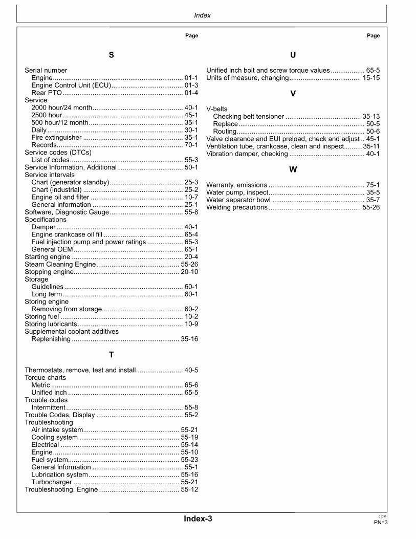
Index
Page
S
Serial numberEngine..................................................................... 011Engine Control Unit (ECU)...................................... 013Rear PTO................................................................ 014
Service2000 hour/24 month................................................ 4012500 hour................................................................ 451500 hour/12 month.................................................. 351Daily ........................................................................ 301Fire extinguisher ..................................................... 351Records................................................................... 701
Service codes (DTCs)List of codes............................................................ 553
Service Information, Additional................................... 501Service intervalsChart (generator standby)....................................... 253Chart (industrial) ..................................................... 252Engine oil and filter ................................................. 107General information ................................................ 251
Software, Diagnostic Gauge....................................... 558SpecificationsDamper ................................................................... 401Engine crankcase oil fill .......................................... 654Fuel injection pump and power ratings ................... 653General OEM.......................................................... 651
Starting engine ........................................................... 204Steam Cleaning Engine............................................ 5526Stopping engine........................................................ 2010StorageGuidelines............................................................... 601Long term................................................................ 601
Storing engineRemoving from storage........................................... 602
Storing fuel ................................................................. 102Storing lubricants........................................................ 109Supplemental coolant additivesReplenishing ......................................................... 3516
T
Thermostats, remove, test and install......................... 405Torque chartsMetric ...................................................................... 656Unified inch ............................................................. 655
Trouble codesIntermittent .............................................................. 558
Trouble Codes, Display .............................................. 552TroubleshootingAir intake system................................................... 5521Cooling system ..................................................... 5519Electrical ............................................................... 5514Engine................................................................... 5510Fuel system........................................................... 5523General information ................................................ 551Lubrication system................................................ 5516Turbocharger ........................................................ 5521
Troubleshooting, Engine........................................... 5512
Page
U
Unified inch bolt and screw torque values .................. 655Units of measure, changing...................................... 1515
V
VbeltsChecking belt tensioner ........................................ 3513Replace................................................................... 505Routing.................................................................... 506
Valve clearance and EUI preload, check and adjust .. 451Ventilation tube, crankcase, clean and inspect..........3511Vibration damper, checking ........................................ 401
W
Warranty, emissions ................................................... 751Water pump, inspect................................................... 355Water separator bowl ................................................. 357Welding precautions ................................................. 5526
Index3 010311
PN=3

Index
Index4 010311
PN=4

John Deere Service Keeps You on the Job
DX,IBC,A 1904JUN901/1
DX,IBC,B 1904JUN901/1
DX,IBC,C 1904JUN901/1
DX,IBC,D 1904JUN901/1
John Deere PartsWe help minimize downtime by putting genuine JohnDeere parts in your hands in a hurry.
That’s why we maintain a large and varied inventory—tostay a jump ahead of your needs.
TS100—UN—23AUG88
The Right ToolsPrecision tools and testing equipment enable our ServiceDepartment to locate and correct troubles quickly . . . tosave you time and money.
TS101—UN—23AUG88
WellTrained TechniciansSchool is never out for John Deere service technicians.
Training schools are held regularly to be sure ourpersonnel know your equipment and how to maintain it.
Result?
Experience you can count on!
TS102—UN—23AUG88
Prompt ServiceOur goal is to provide prompt, efficient care when youwant it and where you want it.
We can make repairs at your place or at ours, dependingon the circumstances: see us, depend on us.
JOHN DEERE SERVICE SUPERIORITY: We’ll be aroundwhen you need us.
TS103—UN—23AUG88
IBC1 010311
PN=159

John Deere Service Keeps You on the Job
IBC2 010311
PN=160

John Deere Service Keeps You on the Job
IBC3 010311
PN=161