Embed Size (px)
Citation preview
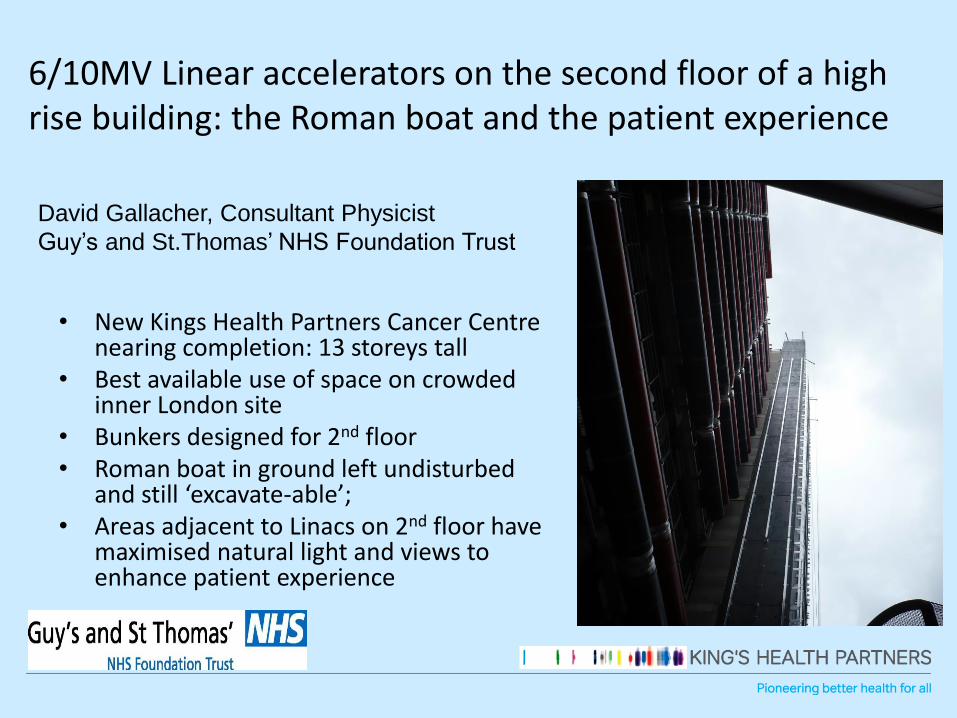
6/10MV Linear accelerators on the second floor of a high rise building: the Roman boat and the patient experience
• New Kings Health Partners Cancer Centre nearing completion: 13 storeys tall
• Best available use of space on crowded inner London site
• Bunkers designed for 2nd floor• Roman boat in ground left undisturbed
and still ‘excavate-able’;• Areas adjacent to Linacs on 2nd floor have
maximised natural light and views to enhance patient experience
David Gallacher, Consultant Physicist
Guy’s and St.Thomas’ NHS Foundation Trust

KHPCC Level2: 6 Linac Bunkers at 6/10MV

The solution?
• Use dense aggregate proprietary blocks
• Blocks have iron and other added materials to increase mass density
• V250 blocks = 4000kg.m-3
• V300 blocks = 5000kg.m-3
• Enable shield thickness to be reduced
• Also, service plant areas immediately above on 3rd
floor, with reduced height and low occupancy
• Service area below, on 1st floor, also with reduced height and low occupancy

Data: Shielding Materials (Veritas)• Supplied Data at 10/6MV Primary X-Rays
• V250 – TVL=238/211mm
• V300 – TVL=187/165mm
• Standard Concrete* – TVL=389/343mm
• Lead – TVL=56/56mm
• Supplied Data at 10/6MV Leakage X-Rays
• V250 – TVL=188/170mm
• V300 – TVL=147/135mm
• Standard Concrete* - TVL=305/279mm
• Lead – TVL=46/46mm*at concrete density of 2350kg.m-3

Shielding Materials (Veritas)• Supplied Data for Neutrons
• V250 – TVL=165mm
• V300 – TVL=165mm
• Standard Concrete* – TVL (fast neutrons from head leakage)=210mm[1]
• BPE – TVL=97mm
Note that the TVL for neutron shielding is not greatly lower than that for standard concrete *at concrete density of 2350kg.m-3
• [1] McGinley, PH, Shielding techniques for radiation oncology facilities, Medical Physics Publishing, Wisconsin, 1998

Calculations I
• X-Rays: use standard techniques: NCRP151, IPEM75
• t= TVL1 + (n-1)TVLe
• Allows for 1st TVL change, build up depth, equilibrium
• For composite barriers after the initial barrier thickness applied at TVL1 all subsequent thicknesses applied using respective TVLe values
• Calculate ‘effective thickness’ of concrete for further calculations and oblique ray path correction

Calculations II
• X-Rays and neutrons: use ‘mean ray path’ method for primary and leakage X-rays
• t(effective,MRP)=t(1+cos(θ))/(2cos(θ))• For oblique incidence at barriers the full slant
thickness was used by supplier: this was contested, usual method is to:
• (a) add 1-2 HVL to barrier thickness calculated for slant;
• (b) use MRP method;• (c ) use Biggs slant correction factors• (b) and (c ) are practically equivalent for 6/10MV X-
rays
Calculations III
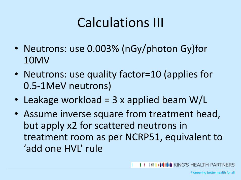
• Neutrons: use 0.003% (nGy/photon Gy)for 10MV
• Neutrons: use quality factor=10 (applies for 0.5-1MeV neutrons)
• Leakage workload = 3 x applied beam W/L
• Assume inverse square from treatment head, but apply x2 for scattered neutrons in treatment room as per NCRP51, equivalent to ‘add one HVL’ rule

V300V250
Lead
SteelBPE
BPE
Composite Primary Beam Shield

Composite Primary Beam Shields: Second Floor KHPCC

Shielding Report #1: 21/10/2013

Shielding Report #1: 21/10/2013
V300

Shielding Report #1: 21/10/2013

Shielding Report #1: 21/10/2013

Beam Tapers: Floor Shielding

[4a] Secondary Barrier Calculation - Point P; Leakage X-RAYS [4b] Patient Scatter
Ratio of monitor units per cGy for leakage no unit MU/cGy 3 3
Leakage dose per day at 1 metre Gy/day 360 360 Dose rate at isocentre
Leakage dose per year (for leakage calculation) Gy/y 90000 90000 Scatter Factor 1.20E-03 0.00115
60 deg
scatter
Orientation Factor for calculation point Op 1.0 1.0 U=1 for sec barrier Beam Area (cm2) 1600 1600 cm^2
Distance from source isocentre m Ls 7.08 7.08 metres from Iso-C Usage Factor 0.66 0.66
60 degree
scatter
Concrete to be added mm 0 0 mm concrete Dpri (m) 1 1 m
Steel to be added mm 0 0 mm steel Dsec (m) 7.08 7.08 m
Concrete V-250 to be added mm 0 0 mm concrete V-250 Ref Beam Area F (cm2) 400 400 cm^2
Concrete V-300 to be added mm 254 254 mm concrete V-300
Lead to be added mm 0 0 mm lead
BPE to be added mm 0 0 mm BPE
Obliquity angle (to the barrier normal) degrees Phi 39 39 degrees
Monitor units per minute MU/min Mu 800 800
Effective Dose rate at 1 metre Gy/min DR DR0 x F x (Mu/Mnorm) 0.008 0.008 Effective Dose rate at 1m 8 8 Gy/min
Unattenuated dose rate at point P Gy/hr Dru DR x 60 / Ls^2 0.0096 0.0096 Unattenuated dose rate 0.0460 0.0440 Gy/hr
Equivalent concrete thickness of barrier mm Te (C+Ta+(SxTVLcs/TVLss))/cos(Phi) 546 536 Equivalent concrete 546 536 mm
Slant thickness of barrier mm 702 689 Slant thickness of barrier 702 689 mm
Oblique thickness of barrier (MRP method) mm 624 612 Oblique thickness (MRP) 624 612 mm
Oblique thickness of barrier (DG method) mm 605 586 Oblique thickness DG 605 586 mm
Attenuation factor (secondary) As exp(-ln(10) x Te/ TVLcs) 1.05E-02 1.42E-02 Attenuation factor (scatter) 1.59E-03 2.81E-03
Instantaneous dose rate uSv/hr Dinst Dru x As x 10^6 100.54 136.32 Instantaneous dose rate 73.25 123.61 uSv/h
Dose per hour in this modality uSv Dhr Dinst x R x Op \ MU/cGy factor 6.284 8.520 Dose per hour in this modality 1.007 1.700 uSv/h
Fraction of intended planned workload used per mode fmode 1 1
Fraction of intended planned workload used
per mode 1 1
Time Averaged Dose Rate (TADR) uSv/hr Dta fmode(1)*Dhr[6MV]+fmode(2)*Dhr[10MV] 14.80400 ***
Time Averaged Dose Rate
(TADR) 2.707 *** uSv/h
Total Dose per year (12 hour days) uSv/y 44412 uSv/year Total Dose per year 12h 8121 uSv/year
Occupancy factor for area T 1 *** Occupancy factor for area 1 ***
TADR with occupancy (TADR2000) uSv/hr Dta2000 14.80 *** TADR2000 2.707 *** uSv/h
Annual Effective Dose (secondary 2000 hours) uSv Dann(sec) 29608 uSv/year Annual Dose 2000 hours) 5414 uSv/year
[5] Secondary Barrier Calculation - Point P: NEUTRONS
Ratio of monitor units per cGy for leakage no unit MU/cGy 3 3
Leakage dose per day at 1 metre Gy/day 360 360
Leakage dose per year (for leakage calculation) Gy/y 90000 90000
Neutron Leakage Fraction (%) % (n)Gy/(p) Gy 0 0.003 %
Total neutron dose from direct neutron dose equivalent factor 0 2
Neutron Quality Factor (c.1MeV) Sv/Gy (n)Sv/(n)Gy 10 10
Neutron dose per year at 1 metre Sv/y 0.0 54.0
Orientation Factor for calculation point Op 1.0 1.0
Distance from source isocentre m Ls 7.08 7.08
Thickness of shielding BPE mm Ls 0 0
Thickness of shielding concrete mm Ls 0 0
Thickness of shielding concrete V-250 mm Ta 0 0
Thickness of shielding concrete V-300 mm 254 254
Obliquity degrees Phi 39 39
Obliquity modifying factor (BIR formula) 1.13 1.13 applied in this case
Attenuation Factor BPE 1.00E+00 1.00E+00
Attenuation Factor concrete 1.00E+00 1.00E+00
Attenuation Factor concrete V-250&V-300 4.42E-02 1.85E-02 Uses combined TVL for both materials
Effective Dose rate at point of interest uSv/y N/A 19948 uSv/year
Dose per hour in this modality uSv/hr N/A 6.649
Occupancy factor for area T N/A 1.00
TADR with occupancy (TADR2000) uSv/hr N/A 6.649
Instantaneous Dose Rate uSv/hr N/A 106.39 uSv/h
Annual Effective Dose (2000h) uSv/year N/A 13298 uSv/year
Shielding Report #1: 21/10/2013

P8 (L2,4,6) - through wall 8 Gy/min - leakage barrier 0.1 0.1 0.011 23 34
P9 (L1) - into corridor 8 Gy/min - leakage barrier 3.8 1.9 0.115 231 346
P9 (L2-6) - adjacent bunker 8 Gy/min - leakage barrier 4.7 2.4 0.144 288 431
P10 (L1) 8 Gy/min - primary barrier 19.2 7.2 0.118 237 356
P10 (L2-6) 8 Gy/min - primary barrier 23.4 8.8 0.144 289 433
P11 (L1) 8 Gy/min - primary barrier 10.7 5.2 0.335 669 1004
P11 (L2-6) 8 Gy/min - primary barrier 4.7 2.4 0.143 287 430
P12 (L1) 8 Gy/min - primary barrier 2.6 2.5 0.226 452 677
P12 (L2-6) 8 Gy/min - primary barrier 1.0 1.0 0.083 166 250
Column 1 (outside) 8 Gy/min - leakage barrier 5.2 4.2 0.394 788 1183
X1 -> P13 (missing steel next column) 8 Gy/min - leakage barrier 21.8 16.1 1.466 2933 4399
P13 (X1->P13 + P12(L2-6) ) 8 Gy/min - leakage barrier 22.8 17.0 1.550 3099 4649
P14 (as proposed) 8 Gy/min - leakage barrier 366.3 289.1 24.160 48320 72481
P14 (with Pb+BPE section) 8 Gy/min - leakage barrier 7.5 7.4 0.478 955 1433
P18 8 Gy/min - leakage barrier 2.2 1.7 0.154 309 463
Column 3 (control room) 8 Gy/min - leakage barrier 4.4 3.4 0.323 645 968
Column 3 (25 mm extra steel) 8 Gy/min - leakage barrier 2.1 1.7 0.163 325 488
X1 -> P15 (missing steel next column) 8 Gy/min - leakage barrier 4.2 3.3 0.299 599 898
P15 (X1->P15 + P8(L2-6) ) 8 Gy/min - leakage barrier 4.4 3.5 0.311 622 933
X4 -> P16 8 Gy/min - leakage barrier 225.6 174.0 14.366 28732 43098
X4 -> P16 with extra shielding Pb+ BPE 8 Gy/min - leakage barrier 2.5 2.5 0.175 351 526
X5 -> P16 with extra shielding Pb+BPE 8 Gy/min - leakage barrier 3.5 3.4 0.238 477 715
P16 (with extra shielding Pb+BPE) 8 Gy/min - leakage barrier 6.0 5.8 0.414 828 1241
X4 -> P17 (missing steel) 8 Gy/min - leakage barrier 2.2 1.7 0.156 313 469
P8extended (L5) - through door 8 Gy/min - leakage barrier 4.5 4.5 0.334 668 1001
P17 (X4->P17+P8ext(L5) ) 8 Gy/min - leakage barrier 6.7 6.2 0.490 980 1471
X4 -> P17 (extended steel) 8 Gy/min - leakage barrier 1.1 0.9 0.081 162 243
P17 (X4->P17ext steel +P8ext(L5) ) 8 Gy/min - leakage barrier 5.6 5.4 0.415 830 1244
Shielding Report #1: 21/10/2013
P14: neutron dose is 28% of the total, scatter 11%, leakage 61%

Shielding Report #1amended: added one extra V300 block adjacent to door surround

Shielding Report #1amended with one extra block: 24/01/2014

SUMMARY SECTION
Wall A - primary barrier IDR (beam)
IDR (one
min.) TADR Occupancy Total Dose
TADR200
0
(µSv/h) (µSv/h) (µSv/h) Factor per Year (µSv) (µSv/y)
[2] Primary Barrier - X-rays 0.00 0.00 0.000 1 0.0 0.0
[3] Primary Bariier - Neutrons 0.00 0.00 0.000 1 0.0 0.0
TOTAL 0.0 0.0 0.000 0 0
SUMMARY SECTION
Wall A - secondary barrier IDR (beam)
IDR (one
min.) TADR Occupancy Total Dose
TADR200
0
(µSv/h) (µSv/h) (µSv/h) Factor per Year (µSv) (µSv/y)
[4a] Secondary Barriers - Leakage X-Rays 3.89 3.89 0.397 1 1191 794
[4b] Secondary Barriers - Scatter X-Rays 0.01 0.01 0.000 1 1 1
[5] Secondary Barriers - Neutrons 14.72 14.72 0.920 1 2760 1840
TOTAL 18.6 18.6 1.32 3952 2635
SUMMARY TOTALS
LOCATION: P16: X4->P16 from Iso-C
Maximum IDR (beam on) calculated 18.62 µSv/h
Maximum IDR (averaged over one minute) 18.61 µSv/h
Maximum TADR calculated 1.317 µSv/h
TADR2000 (combined) 2635 µSv/year
Total Dose per year (full occupancy 12h days) 3952 µSv/year
Dose Constraint for location (with occupancy factor) 300 µSv/year
Occupancy Factor 0.2 --
Total allowed dose per year in location (100%
occupancy) 1500 µSv/year
Meet design constraints No -- Only East Head Position
Shielding Report #1amended: 24/01/2014

APPENDIX #5 SUMMARY SHEET Version Date: 24/01/2014 Shielding Plan Date: Amendment
Part: 1 SK121813-02
Location Condition
Max (Beam
on) Averaged Max TADR2000 Total Dose
IDR IDR TADR (combined) (Full occ.)
µSv/h µSv/h µSv/h µSv/year µSv/year
X4 -> P16 HEAD EAST ONLY 8 Gy/min - leakage barrier 12.1 11.6 0.456 913 1369
X4->P16 8 Gy/min - leakage barrier 18.6 18.6 1.317 2635 3952
X5 -> P16 8 Gy/min - leakage barrier 13.1 13.1 1.200 2399 3599
P16 (combined X4->P16 & X5->P16) 8 Gy/min - leakage barrier 31.8 31.7 2.517 5034 7551
Shielding Report #1amended: 24/01/2014

X1->P15 8 Gy/min - leakage barrier 5.5 4.2 0.383 766 1150 1.0
X2->P15 8 Gy/min - leakage barrier 0.1 0.1 0.010 20 30 1.0
P15 (X3->P15 + X4->P15) 8 Gy/min - leakage barrier 5.6 4.4 0.393 787 1180 1.0
X4->P16+X5->P16 (Veritas RPs) 8 Gy/min - leakage barrier 9.2 8.0 0.606 1213 1819 0.2
X4->P16+X5->P16 (Alternative RPs) 8 Gy/min - leakage barrier 10.6 8.6 0.722 1443 2165 0.2
X4-P16 (Head - East) 8 Gy/min - leakage barrier 6.9 6.7 0.537 1075 1612 0.2
X4 -> P17 (through extra block) 8 Gy/min - leakage barrier 1.7 1.4 0.121 243 364 0.2
P8extended (L5) - through door 8 Gy/min - leakage barrier 4.5 4.5 0.334 668 1001 0.2
P17 (X4->P17+P8ext(L5) ) 8 Gy/min - leakage barrier 6.2 5.8 0.455 910 1365 0.2
Door 1 8 Gy/min - leakage barrier 7.4 7.3 0.547 1095 1642 0.2
X3->P19, Borough Wing) 8 Gy/min - leakage barrier 1.0 0.9 0.078 156 234 0.5
X4->P19, Borough Wing) 8 Gy/min - leakage barrier 0.8 0.8 0.067 133 200 0.5
X5->P19, Borough Wing 8 Gy/min - leakage barrier 1.5 1.2 0.103 207 310 0.5
P19 (X3, X4 and X5) 8 Gy/min - leakage barrier 3.3 2.8 0.248 496 745 0.5
C1 8 Gy/min - primary barrier 39.5 14.8 0.259 521 782 0.1
C2 8 Gy/min - primary barrier 56.9 21.3 0.355 711 1067 0.1
C3 8 Gy/min - primary barrier 8.7 3.3 0.053 106 158 0.1
L1 8 Gy/min - leakage barrier 3.8 1.9 0.126 252 379 0.1
L2 8 Gy/min - leakage barrier 0.2 0.1 0.013 26 39 0.1
F1 8 Gy/min - primary barrier 16.6 6.2 0.249 549 824 0.1
F2 (alt. ray-path) 8 Gy/min - primary barrier 52.3 19.6 0.659 1327 1990 0.1
F3 8 Gy/min - primary barrier 11.2 4.2 0.164 333 499 0.1
FL1 8 Gy/min - leakage barrier 7.8 3.8 0.267 533 800 0.1
FL2 8 Gy/min - leakage barrier 6.5 5.1 0.475 950 1425 0.1
FL2 (void space) 8 Gy/min - leakage barrier 21.6 16.2 1.507 3015 4522 0.1
Duct Penetration1 8 Gy/min - leakage barrier 24.6 11.9 0.781 1562 2343 0.1
Duct Penetration2 8 Gy/min - leakage barrier 0.4 0.4 0.038 76 114 0.1
At corner top wall facing Borough Wing 8Gy/min - leakage barrier 10.3 9.4 0.978 1955 2933 0.5
COLOUR HIGHLIGHT KEY Changes DG comments on 27/2/2014 Veritas report
Satisfactory - no issues identified FL2: void space accounted for - see Appendix #2
Advisory - there may be actions attached L3: over wall shielding towards Boruhg Wing - shielding deficit
Warning - serious issues identified

25mm steel shim
Oblique Ray path through structural beam deficit: shim added

Solution: 3xV300+1xV250 blocks on door surrounds
Extra 127mm V250
block

Problems solved….

Build Stage: Primary Barrier Taper Level 3 above Linacs

Build Stage: Primary Taper above Linac

Build Stage: Level 3 Linac Shielding

Build Stage: Level 2 Linac Floor Shielding

Build Stage: Level 2 Walls

Build Stage: Proximity of other buildings

Build Stage: Level 2 Walls

Build Stage: Level 2 Walls

Build Stage: Level 2 Walls packed ‘grout gap’

Build Stage: Door Frames

Build Stage: Door Frame/Exterior Window

Build Stage: Angled Physics Ports

Build Stage: unfilled door casing

Build Stage: 11tonne door

Build Stage: Level 2 Outside Walkway – occupancy Vs distance to near buildings?

Conclusions• Check assumptions made in design
• Detailed calculation always required, especially with a novel design challenge i.e. on the 2nd floor with adjacent buildings
• Beware of neutron dose with high density/high Z aggregated concrete blocks, it becomes significant factor
• High density materials can reduce barrier thicknesses when space is at premium
• Regular inspection during build essential to head off problems later

References
• [1] McGinley, PH, Shielding techniques for radiation oncology facilities, Medical Physics Publishing, Wisconsin, 1998
• [2] NCRP Report No.151, Structural Shielding, Design and Evaluation for megavoltage X-and Gamma Ray Radiotherapy Facilities
• [3] IPEM Report No.75, The design of radiotherapy treatment room facilities, IPEM, York, 1997
• [4] Biggs, PJ, Styczynski, JR, Do angles of obliquity apply to 30° scattered radiation from megavoltage beams?, Health Physics, 98(4), 425-432, 2008