Embed Size (px)
Citation preview

Materiel Test Procedure 5-2-58710 August 1967 White Sands Missiles Range
U. S. ARMY TEST AND EVALUATION COMMANDCOMMON ENGINEERING TEST PROCEDURE
THE PHOTOSTRESS METHOD OFSTRUCTURAL DATA ACQUISITION
1. OBJECTIVE
The objective of this MTP is to provide a procedure for determiningthe magnitudes and directions of stresses in test specimens using the photo-stress method of structural data acquisition.
2. BACKGROUND
A knowledge of the structural characteristics of materiel is essentialin determining suitability for expected usage. By determining the magnitudesand direction of surface stresses in a structural body, loaded in a mannersimilar to expected usage, the structural adequacy of the body can be deter-mined.
The photostress method of stress analysis is based on the fact thatcertain meterial, e.g., plastic, become birefringent when subjected to stress,and the degree and the orientation of the birefriengency is mathematicallyrelated to the direction and differences of the principal stresses actingin the material. When a thin layer of such material is applied to the surfaceof a test item such that the surface stresses in the test item are transferedto the plastic coating, a measure of the amount and direction of the bire-fringency in the plastic will allow determination of the directions and differ-ences of the principal surface stresses of the test item. The direction andamount of birefringency in the plastic coating can be determined by passingpolarized light through the plastic coating and then measuring the effectof the birefringency on the polarized light.
3. REQUIRED EQUIPMENT
Some of the items listed below are described in Appendix C.
a. Facility to load the test specimen to stimulate service loading.b. Reflective polariscopec. Optical compensatorsd. Liquid or sheet plastic having applicable strain constrant(K).e. Oven for heating plasticf. Provisions for tracing and photographing patterns.g. Calibration beamsh. Applicable hand tools for molding, applying and removing plastic.
4. REFERENCES
A. Hetenyi, M., Handbook of Experimental Stress Analysis, John Wiley &Sons, Inc., New York, 1950.
B. Frocht, M.M., Photoelasticity, John Wiley & Sons, Inc., New York,1941.
-1-
Loordaw 0$"1

MTP 5-2-58710 August 1967
C. McMaster, R. C., Nondestructive Testing Handbook, Vol. II,The Ronald Press Co., New York, 1959.
D. Dove, Richard C. and Adams, Paul H., Experimental Stress Analysisand Motion Measurement, Charles E. Merrill Books, Inc., Columbus,Ohio, 1964.
E. How to Select Photoelastic Coatings, Materials in Design Engineering,September 1964.
F. Mclver, Robert W., Structural-Test Applications Utilizing LargeContinuous Photoelastic Coatings, Experimental Mechanics, Januaryand February 1965.
5. SCOPE
5.1 SUMMARY
This MTP describes methods for performing photostress data acquisition,including: the selection, application and calibration of the plastic coating,the acquisition of photostress data using a reflective polarscope, thedetermination of the directions of principal stresses by the constructionof stress trajectories, and the determination of the difference in magnitudeof principal stresses (or maximum shearing stress).
NOTE: Many of the terms used in this MTP are explained inAppendices A and B.
5.2 LIMITATIONS
No attempt will be made to describe the analysis of stress in anyspecific object or structure. The procedures outlined in this MTP are of asufficiently general nature to be applicable to most cases of two dimensionalphotostress data acquisition.
6. PROCEDURES
6.1 PREPARATION FOR TEST
6.1.1 Selection of Plastic
The plastic coating shall be selected using the following criterion.
a. Sheet or liquid plastic may be used. Sheet plastic shall normallybe prefered over the liquid forms since it can be bonded to the test item atroom temperatures and its thickness is uniform and predetermined. However, theirregular shape of the surface or the size of the area to be tested may requirethe use of liquid plastic. Liquid plastic may be directly applied to the testitem surface by brush or spray or it may be used to make up castings of speciallyshaped sheet plastic. For additional selection criterion see Reference E and F.
b. The thickness of the plastic applied shall be the optimum relation-ship between being thin enough to not materially reinforce the test item andbeing thick enough to bring out the desired degcee of photostress resolution.
0-2-

. MTP 5-2-58710 August 1967
C. The plastic shall have a strain constant clompatible with thestrains to which the test item will be subjected.
NOTE: Plastics are available in high strain and low strain types.The maximum strain values to which the plastics can be sub-'jected without loss of accuracy are listed on the technicaldata sheets for plastics. See also Appendix C, Pages C-7and C-8.
6.1.2 Preparation of Surface
The theory of photostress techniques is based on the assumption thatthe plastic coating be subjected to the same stress and strain as the surfaceof the test item. To ensure this, it is essential that a strong and continuousbond exist between the surface of the test item and the plastic coating. Toensure this bond the surface must be prepared as follows:
a. All paint and primer coatings shall be removed using a suitablestripper.
NOTE: The presence of paint may result in the non-adhesion of theplastic, the introduction of impurities into the adhesiveor a tendency of the paint to creep under load, All of theabove may affect the outcome of the test.
* b. The surface shall then be roughened by sanding with emery paperor with a mild grit blast.
c. If the surface is not now reflective it shall be polished andthen slightly roughened or painted with applicable reflective paint.
NOTE: If the plastic to be applied has a reflective backing thisstep may be omitted. Also this step may be omitted if theadhesive to be used is reflective, e.g., photo stress re-flective bonding adhesive.
d. The surface should be covered with paper to prevent contaminationprior to bonding.
6.1.3 Application of Plastic
a. Sheet Plastic
1) Sheet plastic shall be applied by bonding it to the testitem using a special adhesive which is applied like anyordinary cement.
2) The adhesive shall be allowed to harden for 25 hours.
b. Liquid Plastic
1) The liquid plastic shall be applied to the test item bybrushing, spraying, pouring or dipping.
0-3-

MTP 5-2-58710 August 1967
2) The test item shall be heated to from 150 to 230 degreesFahrenheit (F°) depending upon the facility used.
3) Allow a few minutes for the plastic to harden, then applya second layer.
4) Repeat this procedure until the desired thickness of plasticis attained (usually from 0.001 to 0.060 inches).
c. Casting and molding of liquid plastic
NOTE: This procedure is discussed in detail in Reference F.
1) A flat sheet is made by pouring some liquid plastic andsome hardner into a level mold.
2) The plastic is polymerized at 122=F for approximately 45minutes, and then removed from the mold.
3) The resulting sheet can then be shaped over the test itemand bound to it with special adhesive.
6.1.4 Calibration of the Plastic
a. Measure the thickness of the plastic on the test item by directmeasure using a micrometer or a small field meter.
NOTE: To 'use the small field meter, focus first on the surfaceof the plastic surface and then on the surface of thetest item. The difference in focus can be read on themicrometer attachment,
b. Apply a similar layer of plastic to a standard testing beam.c. Record the dimensions of the beam as shown below:
12T
d. Record the following physical characteristics of the beam:e.g., density.
e. Load the beam as a cantilever with a known load while observingthe beam with a reflective polarscope using monochromatic light.
f. Record the photostress patterns as they develop.g. Repeat steps e and f with other known loads.h. Calculate and record principal strain for each load using the
standard formula for a beam in flexure.i. From the data recorded in steps f and h above calculate the value
of the strain constant (K) using equation 6. 4 .1.c.
0-4-

* MTP 5-2-58710 August 1967
6.2 TEST CONDUCT
6.2.1 Identification of Isoclinics
NOTE: Isoclinic lines are lines through points where the principalstresses are aligned in the same direction.
a. The quarter wave plates on the reflective polarscope shall beremoved from the polarscope optical path so that the polarscope is in the planepolarized mode of operation.
b. The analyzer shall be rotated to the crossed or parallel positiondepending upon whether a light or dark background is desired.
NOTE: For the following discussion it will be assumed that thebackground is light (crossed position)
c. The test item shall be loaded in accordance with MTP 5-2-504 orother applicable MTP.
d. The test item shall be inspected and isoclinics shall be identifiedand their positions recorded by marking the test item, by suitable tracing orby photographic means.
NOTE: Procedures for distinguishing isoclinics from isochromaticsare found in reference D. In general if monochromaticlight is used, both isoclinics and isochromatics are thesame color but if the plane polarscope is converted intoa circular polarscope the isoclinics will disappear and onlythe isochromatics will remain. If white light is usedthe isoclinics will appear as black lines and the isochromaticswill appear as bands of multi colored lines.
e. The polarscope shall be rotated 100 with respect to the testitem and step (d) shall be repeated.
f. Step (e) shall be repeated until the polarscope has been rotated1800 with respect to the test item.
6.2.2 Identification of Isochromatic Fringe Order
Isochromatics are regions where at all points within the regionthe difference in the principal stresses are the same. Isochromatics appearas black bands when the test item is illuminated with monochromatic light. Ifthe light is plane polarized, insoclinic lines will also appear as black bands.However, if the ploarizer is rotated the isochromatics will remain stationarywhile the isoclinics change position and disappear. If the light is circularlypolarized only the isochromatic bands will appear. If the test item is illumin-ated with white light the isochromatic lines will appear as colored bands. Ifthe white light is plane polarized isoclinic lines will appear as black bands.If the white light is circularly polarized only the isochromatic bands willappear. White light is usually used when the maximum number of fringe ordersis less than four. Above fringe order three the individual color fringes beginto blend and become indistinguishable.
0-5-
MTP 5-2-58710 August 1967
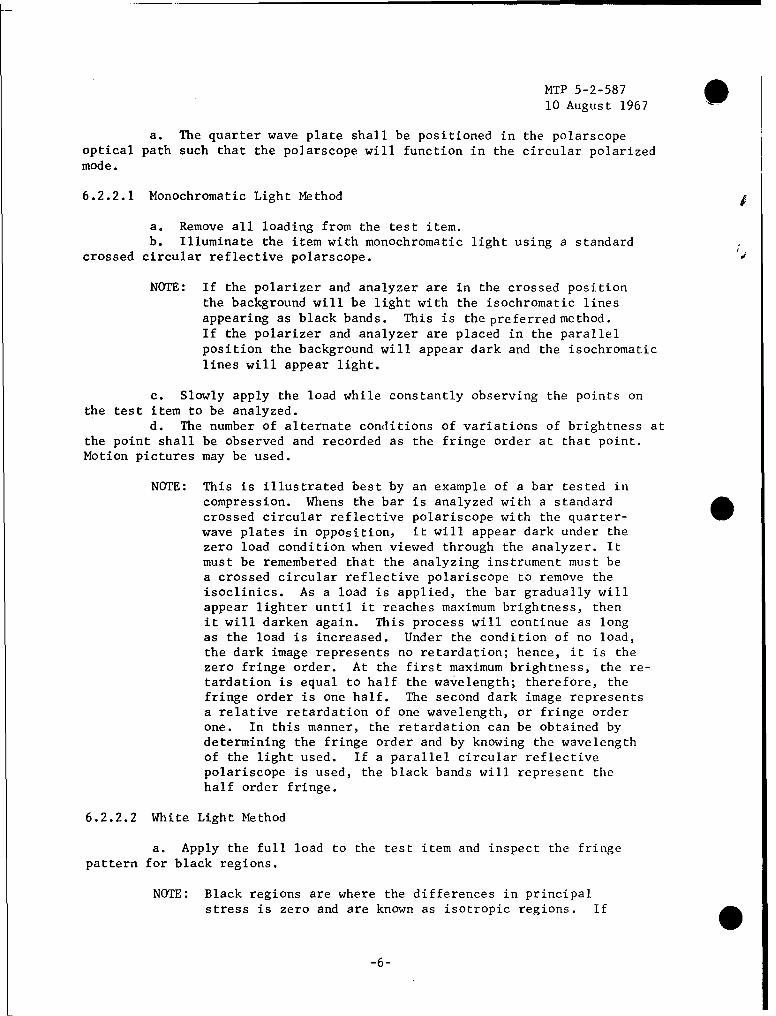
a. The quarter wave plate shall be positioned in the polarscopeoptical path such that the polarscope will function in the circular polarizedmode.
6.2.2.1 Monochromatic Light Method
a. Remove all loading from the test item.b. Illuminate the item with monochromatic light using a standard
crossed circular reflective polarscope. S
NOTE: If the polarizer and analyzer are in the crossed positionthe background will be light with the isochromatic linesappearing as black bands. This is the preferred method.If the polarizer and analyzer are placed in the parallelposition the background will appear dark and the isochromaticlines will appear light.
c. Slowly apply the load while constantly observing the points onthe test item to be analyzed.
d. The number of alternate conditions of variations of brightness atthe point shall be observed and recorded as the fringe order at that point.Motion pictures may be used.
NOTE: This is illustrated best by an example of a bar tested in
compression. Whens the bar is analyzed with a standardcrossed circular reflective polariscope with the quarter- 4
wave plates in opposition, it will appear dark under thezero load condition when viewed through the analyzer. Itmust be remembered that the analyzing instrument must bea crossed circular reflective polariscope to remove theisoclinics. As a load is applied, the bar gradually willappear lighter until it reaches maximum brightness, thenit will darken again. This process will continue as longas the load is increased. Under the condition of no load,the dark image represents no retardation; hence, it is thezero fringe order. At the first maximum brightness, the re-tardation is equal to half the wavelength; therefore, thefringe order is one half. The second dark image representsa relative retardation of one wavelength, or fringe orderone. In this manner, the retardation can be obtained bydetermining the fringe order and by knowing the wavelengthof the light used. If a parallel circular reflectivepolariscope is used, the black bands will represent thehalf order fringe.
6.2.2.2 White Light Method
a. Apply the full load to the test item and inspect the fringepattern for black regions.
NOTE: Black regions are where the differences in principal
stress is zero and are known as isotropic regions. If
-6-

. MTP 5-2-58710 August 1967
such a region is not present the fringe order can onlybe determined by using the method described in the sectiondiscussing monochromatic light, (6.2.2.1).
b. The black regions will be identified as fringe order zero.y c. Color photographs shall be taken of the fringe pattern and retained
as test data.d. The fringe order at any desired point shall be determined and
recorded using the "tint of passage" method.
NOTE: The tint of passage is the transition from the red to theblue or green. This is a sharp and easily recognized line,and it should be used for the reference fringe. The tintof passage of first order corresponds to a relative retard-ation of 2.27 X 10 5 inches, as stated in Reference C. Thetint of passage of order one (first fringe) is the firsttint of passage encountered when moving away from a blackarea (location of zero stress) or a fringe of zero order.It must be remembered that the analyzing instrument, aspreviously stated, must be a crossed circular reflectivepolariscope. The subsequent tints of passage are fringestwo, Three, etc., and the relative retardation is 2X2.27X 10- inches, etc. In fringes of higher order, the bluecolor disappears and is replaced by green.
* It mustbe noted that the fringe order is increasing only when thecolor is going from red to green in the direction in which fringes are beingcounted. If the color order is reversed, the operator must deduct fringeorders.
6.2.3 Removal of Plastic
Remove the plastic from the test specimen using a wedge scraper tooland a hot air gun. Any remaining bonding adhesive shall be removed with anexpoxy stripper and a wooden spatula.
6°3 TEST DATA
6.3.1 Calibration of Plastic
Record the following:
a. Thickness of applied plastic coating in inchesb. Manufactures calibration constant
NOTE: If the manufactures calibration constant is not availableor if additional calibration data is required, record thefollowing additional data.
c. Dimensions of cantilever as described in 6.1.4 c, in inches.
0-7-

MTP 5-2-58710 August 1967
An example of this procedure is shown in Table I.
Table I. Colors and Fringe Orders
COLOR FRINGE ORDER
Black
Yellow
Red
Green or Blue
Yellow
Red
--20
Green
Yellow
Red
3
Green
Yellow
Green
Red
Yellow
Green
Red
-8-

.IMTP 5-2-58710 August 1967
d. Pe physical characteristics of the beam, e.g., density inpounds/(foot)
e. The weight in pounds of the applied loadf. Photostress pattern for the load recorded aboveg. Repeat steps (e) and (f) above for all additional loads.
6.3.2 Identification of Isoclinics
a. Record the isoclinic pattern for each ten degree increment ofrotation of the polarscope.
6.3.3 Identification of Isochromatic Fringe Order
a. Record the fringe order at all points where the stress differenceis desired.
b. Record the average thickness of the plastic coating in inches
6.4. DATA REDUCTION AND PRESENTATION
6.4.1 Calibration of Plastic
a. From equations describing the standard cantilever beam determinethe stress at the surface of the beam at the point under observation.
b. Determine the fringe order at the point under investigation.c. Using the following equation determine *-he optical strain
constant (K).
K = 2st
n
Where:
n = fringe order at pointt = thickness of plastic in inchess = surface stress at point
NOTE: This equation is a special case of
S1 - S2 = Kn
2t
Where: in the case of a cantilever beam S= 0.
6.4.2 Construction of Stress Trajectories
NOTE: Stress Trajectories (or isostatics) are lines parallel ornormal to the two principal-stress directions at all pointsthrough which they pass and graphically represent thedirections of the principal stresses.
0-9-

MTP 5-2-58710 August 1967
a. Superimpose the tracings of isoclinics taken at each 10 degreeincrement of rotation of the polarscope on one drawing and label each isoclinicwith the angle of rotation associated with it. e.g., Figure 1.
b. Pick any point A on the first isoclinicc. From point A draw a straight line with a slope equal to the average
of the angles of the first and second isoclinic.d. The point where the straight line crosses the second isoclinic
shall be labeled point B.
F 0
STRESS
TRAJECTORY
ISOCLINIC
BOUNDARYLIEOF MODELD ) LINES
"• •+•J L•SLOPE- 3 2 4 C PINCIPAL
STRESS AXES
3 SLPE " e02
0+3LPE- 2 E -i ,+goo
REFERENCE LINE
Figure 1.
e. From point B draw a straight line with a slope equal to theaverage of the angles of the second and third isoclinic.
f. The point where the straight line crosses the third isoclinicshall be labeled point C.
g. The process shall be continued until the last isoclinic hasbeen crossed.
h. A smooth curve shall be scribed through all the points determinedabove (A, B, C, etc), such that all of the straight lines constructed formchords to the curve.
NOTE: All of the stress trajectories thus formed must form anorthogonal network (intersect only at right angles toeach other and to free boundaries).
6.4.3 Determination of Stress Difference
a. Determine the stress difference at those points where the fringeorder has been determined using the following equation:
-10-

* MTP 5-2-58710 August 1967
S1 - S2 Kn
2t
Where:
t = thickness of plastic in inchesK = stress constant in pounds/inchn = fringe order
-11

MTP 5-2-587
10 August 1967
APPENDIX A
Polarization of Light
The terms "polarization" indicates that some control is exerted4W on the light vector. Light can be plane polarized, circularly polarized, or
elliptically polarized.
Plane Polarization -- When the light vector is confined to a singleplane, the light is said to be plane polarized, as illustrated in Figure a.The plane containing the light vector is called the plane of vibration, andthe plane at right angles to it is called the plane of polarization. Theseplanes are described in Reference A. Ordinary light may be though of as acombination of an infinite number of plane polarized components whose planesof vibration have every conceivable orientation, as illustrated in Figure A-2.
PLANE OF VIBRATION
PLANE OF POLARIZATION
Figure A-1.
Plane Polarization
LINE OF
PROPAGATION
Figure A 2
Ordinary Light (No Control Over Light Vector)
A-1

MTP 5-2-58710 August 1967 0
Circular Polarization -- When the light vector is made to rotateabout the line of propagation with its magnitude remaining constant, it iscircularly polarized. If the vector is plitted at various positions alongits line of propagation, the tips of the vector will form a circular helix.Circularly polarized light is illustrated in Figure A-3.
CIRCULAR HELIX I I
I DIRECTION OF PROPAGATION
Circular Polarization (Right & Left Hand)
Figure A-3.
Elliptical Polarization -- Elliptical polarization essentially isthe same as circular polarization, except that the magnitude of the vectorchanges periodically during rotation. If the vector is plotted at variouspositions along its line of propagation, the tips of the vector will forman elliptical helix, as illustrated in Figure A-4.
ELLIPTICAL HELIX
DIRECTION OF PROPAGATION
Elliptical Polarization (Right & Left Hand) Types o' Polarization
Figure A-4.
Birefringence -- Incident light passing through certain transparentcrystalline materials such as calcite and mica is broken up into two bewhich travel through the material at different speeds. Thus, one beam isretarded with respect to the other. This phenomena is known as birefrigenceor double refraction, and is illustrated in Figure 5. In addition to the
0A- 2

MTP 5-2-587
10 August 1967
naturally birefringent materials, certain plastics become birefrigent whenthey are under strain. A second effect of double refraction is that the twobeams are plane polarized at right angles to each other. The directions ofpolarization corresponds to the transmission axes of the naturally birefringentmaterial or to the directions of the principal strains in the stressed plastic.The axis which retards the beam is called the slow axis, and the other thefast axis.
SLOW AXIS
• • . • -..-.-.--.- ...- FAST AXIS
POLARIZED LIGHT
BIREFRINGENT MATERIALUNPOLARIZEDLIGHTSOURCE
Figure 5. Action of Birefringent Materiel
AA-3

MTP 5-2-58710 August 19'67 !
APPENDIX B
Optical Law of Photostress
In any material which becomes birefringent when stressed, therelative retardation is related to the difference between the principal stresses
-V by:
8n = C(0 1 -1 a)p2t (I)
or
(°- - )p 2Ct (2)
Where:
t = thickness of the photostress plasticC = stress optical constantp = photostress plastic symbol
6n = relative retardation measured when polarized light is traversingthe plastic under normal incidence
CT1 , 92 = principal surface stresses
These derivations are described in Reference C. The equation uses 2t becausethe light is reflected from the work piece, passing through the plastic twice.
Hooke's law for strains states that:
e1 =E E (3)
and C C
E;, (4)•2 E E (4
Where:
E = modulus of elasticity of the plastic6l, 62= principal surface strains
= Poisson's ratio
Therefore,E
2 1 E: 12-ý (5)
and - ) E
(CT - )w = + 4w) (6)
ý 0 p (I + 4p (7)
p
0B-i

MTP 5-2-587
10 August 1967
Where:
w = workpiece symbol
Combining equations (2) and (7),.
an (e, - e2)p Ep2tC (I + Pp) (8)
Since the plastic exactly follows the deformations of the work piece,
( C2 - £2)p = (el - e2)w (9)
so that (61 62) p Ew(- U2 )w = I(+w) (1)
E (1 + p) 2t
E (en)
K (I + ýw 2t (12)
and
(e - C2) =6n (13)2tK
Where:CE
K = P = strain optical constant (14)1 + p
B-2

. 5-2-58710 August 1967
APPENDIX CTEST EQUIPMENT
Polariscopes
The polariscope is an optical device usually employed to producethe required polarized light and to interpret the light patterns in a photo-elastic stress analysis. A polariscope may be plane or circular, and crossed(standard) or parallel.
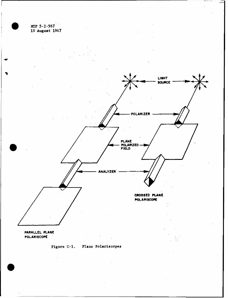
a. Plane Polariscope -- The plane polariscope consists of a lightsource and two polarizing elements arranged as shown in Figure C-I. Thepolarizing element nearer the light source is the polarizer, while the otherone is the analyzer. When the transmission axes of the polarizer and theanalyzer are parallel, the instrument is a parallel polariscope; when thetwo axes are at right angles to each other, it is a crossed polariscope. Asthe name implies, the plane polariscope produces plane polarized light.
b. Circular Polariscope -- The circular polariscope is similar tothe plane polariscope, except that two quarter-wave plates are placed betweenthe polarizer and the analyzer, as shown in Figure C-2. The quarter-waveplates are oriented so that their transmission axes are inclined at anangle of 45 degrees to the axes of the polarizer and the analyzer. The quarter-wave plates may have their fast axes at right angles to each other, or they mayaugment each other. The polarizer and the analyzer may be crossed as shown in. Figure 3, or they may be parallel.
c. Reflective Polariscope -- The reflective polariscope is identicalto the polariscopes described above except that the optical elements arearranged side by side as shown in Figure C-3. The reflective polariscope willbe either circular or plane, depending upon whether the analysis is for thedifference or for the direction of the principal stresses.
Optical Compensators -- The optical compensators are devices whichartificially produce a fringe of a known value at any given point on the testitem. They are used if the number of isochromatics is insufficient for anaccurate whole-field strain difference determination. Usually, they arecalibrated quartz wedges. The equipment operation manuals provide details ontheir use,
e. Large Field Meter -- The large field universal meter is used toanalyze large areas of the test item to obtain the complete picture of stressdifferences and directions of the principal stresses. The large field meter isa portable instrument consisting of an illuminator equipped with a polarizerand an analyzer lying in the same plane. The illuminator may be a source of'either white light or monochromatic light. The polarizer is located in frontof the illuminator, and the operator observes the test item through theanalyzer. The polarizer and analyzer can be rotated independently, or theycan be synchronized to rotate together. The instrument also has two quarter-wave plates, one of which can be placed in front of the polarizer and theother in front of the analyzer to make the instrument a circular polariscope.
The large field meter can be used either for static or for dynamictests. In dynamic testing, the standard illuminator is replaced, either witha stroboscope for direct viewing of the test item under alternating loads,or with a flood light for use with a high speed camera. When a camera isused, it is placed behind the analyzer.
C-l

MTP 5-2-587
10 August 1967
f. Small Field Meter -- The small field meter is used to analyzesmall parts, or for detained analyses at small discontinuities on large testitems. It consists of a microscope equipped with a light source, a polarizer,and an analyzer. The unit can be used to measure the thickness of the plasticby focusing first on the surface of the plastic, then on the surface of thetest item and reading the micrometer attachment. It can be adapted fordynamic stress analyses by attaching a photoelectric cell and an amplifier.
g. Oblique Incidence Meter -- The oblique of incidence meter isused for a point by point determination of the magnitude of each separateprincipal stress. An oblique incidence attachment is made for both thesmall field and the large field meters. Methods for using the method arefound in the reference material.
h. Quarter-Wave Plates -- The quarter-wave plates are plates of abirefringent material which, for a given wavelength of light, produce arelative retardation of one fourth of a wavelength. Plane polarized lightentering a quarter-wave plate with the plane of vibration inclined at anangle of 45 degrees to the transmission axes of the plate will be trans-formed into circularly polarized light, as shown in Figure C-4.
i. Plastic Sheets -- Commercially available plastic sheets aremanufactured and are either clear or metallized on one face and are appliedto the test item with cement. The sheet of plastic may be either the lowstrain or the high strain type. The limit of linear strain/optical responsefor the low strain sheet is a unit strain equal to 2.5 percent. When it isused in temperatures above 250°F, the strain can be 30 percent. The constantK is about 0.1 in the temperature range of minus 44 to plus 85°F. Above 250'F,the value of K drops to 0.03. The allowable strain for the high strain sheetis 30 percent at room temperature with a K value of about 0.02. This type ofplastic is used for stress analysis of highly deformable materials such asrubber. Each plastic sheet is marked with its K value. The variations inK values with temperatures are described in detail in the technical datasheets for the plastics. The same information may be derived by calibratingthe plastic at the desired temperature.
j. Liquid Plastic -- The liquid plastics also are available in bothlow strain and high strain forms. When the low strain liquid plastic is usedat room temperature, it has a limit of strain/optical response of about threepercent, with a K value of approximately 0.1. The high strain liquid plasticat room temperature has a maximum strain value of 30 to 50 percent with a Kvalue of approximately 0.02. The k value also can be determined by calibration.Either form of liquid plastic may be applied by brushing, spraying, or dippingthe test item. Also the liquid plastic cast to from special shapes of sheetplastic as explained in reference.
0C- 2
O HPrr 5-2-58710 August 1967
LIGHTSOURCE "
POLARIZER
PLANESPOLARIZEDFIELD •
9l• ANALYZER'
CROSSED PLANEPOLA RISCOPE
PARALLEL PLANE
POLARISCOPE
Figure C-1. Plane Polariscopes
S

MTP 5-2-58710 August 1967
LIGHTSOURCE
POLARIZER
FAST AXIS IPLANE POLARIZED BEAM
450SLOW AXIS
" - QUARTER-WAVE PLATE
CIRCULAR POLARIZED FIELD
Figure C-2. Circular Polariscope
0

MrP 5-2-587S 10 August 1967
TESTITEM
QUARTER-WAVE PLATE
POLARIZER 4/ ANALYZER
LIGHT SOURCE
5 Figure C-3. Circular Reflective Polariscope

IWP 5-2-58710 August 1967
I -•
PHASE DIFFERENCE X/4TRANSMISSION
AXES
STHICKNESS t
I °
INCIDENT LIGHT
Figure C-4. Action of a Quarter-Wave Plate