Embed Size (px)
Citation preview

278 Chapter 6 NEL
6.16.1 Laminar and Turbulent Flow
A log ride is smooth as long as the water flows evenly. However, the flow and
the ride can become rough where there are dips and sharp curves (Figure 1).
The factors that affect the smooth or rough flow of a fluid are part of the
study of fluids in motion, called fluid dynamics.
As a fluid flows, the forces of attraction between the molecules cause
internal friction, or resistance to the flow. The fluid’s viscosity is a measure of
this resistance to flow. A fluid with a high viscosity, such as liquid honey, has a
large amount of internal resistance and does not flow readily. A fluid with a
low viscosity, such as water, has low internal resistance and flows easily.
Viscosity depends not only on the nature of the fluid, but also on the fluid’s
temperature. As the temperature of a liquid increases, the viscosity generally
decreases because the particles of the liquid have more energy and flow more
easily. As the temperature of a gas increases, however, the viscosity generally
increases because the particles of the gas collide with each other more often,
making it more difficult for them to flow in one direction.Figure 1
The design of a log ride determines
its smoothness.
fluid dynamics the study of the
factors that affect fluids in motion
viscosity the property of a fluid
that determines its resistance to
flow; a high viscosity means a high
resistance to flow
TRYTHIS activity Viscosity
Observe the effect of temperature changes
on the viscosity of various products from
your home (e.g., vegetable oil, honey, clear
shampoo, syrup) when placed in stoppered
test tubes provided by your teacher
(Figure 2). Each tube should also contain
a marble. Obtain a test tube that has been
placed in a cold water bath, invert it, and
measure the time it takes for the marble to
travel through the liquid. Compare your
results with the time it takes for the marble
to travel through the liquid in a test tube
that has been placed in a hot water bath.
Wear gloves when handling the
liquids. Exercise care when using
hot water.
vegetable oil
in test tube
marble
stopper
Figure 2
After you invert the test tube, the
marble moves slowly downward
through the oil.
As a fluid flows, the fluid particles interact with their surroundings and
experience external friction. For example, as water flows through a pipe, the
water molecules closest to the walls of the pipe experience a frictional
resistance that reduces their speed to nearly zero. Measurements show that the
water speed varies from the wall of the pipe (minimum speed) to the centre of
the pipe (maximum speed). If the speed of a fluid is slow and the adjacent
regions flow smoothly over one another, the flow is called a laminar flow
laminar flow fluid flow in which
adjacent regions of fluid flow
smoothly over one another

Fluid Dynamics 279NEL
(Figure 3(a)). The flow of a fluid such as air passing around a smooth object is
also called laminar flow (Figure 3(b)).
Laminar flow is usually difficult to achieve because, as the fluid flows
through or past an object, the flow becomes irregular, resulting in whirls
called eddies (Figure 4). Eddies are common in turbulent flow, a fluid flow
with a disturbance that resists the fluid’s motion (e.g., water encountering
boulders in a river). A fluid undergoing turbulent flow loses kinetic energy as
some of the energy is transformed into thermal energy and sound energy. The
likelihood of turbulence increases as the velocity of the fluid relative to its
surroundings increases.
Section 6.1
low velocity
eddies
high velocity
eddies
(a) (b) (c)
Figure 4
(a) Low turbulence at a low velocity
(b) Higher turbulence at a higher velocity
(c) You can see examples of turbulent flow in this view of Jupiter’s atmosphere.
The Benefits of Turbulence
In some cases, air turbulence is
beneficial, for example, in the
coach’s whistle mentioned on
page 277. When you blow the
whistle, the bead gets knocked
around and increases the
turbulence, which improves the
quality of the sound and increases
its loudness. Air entering the
mouthpiece of a wind instrument
also needs some turbulence in
order to vibrate easily.
DID YOU KNOW??
turbulent flow fluid flow in which
a disturbance resists the fluid’s
motion; it results when fluids cannot
move smoothly around or through
objects
(a) (b)
Figure 3
The length of each vector represents the magnitude of the fluid velocity at that point.
The longer the arrow, the greater the velocity.
(a) Water in a pipe
(b) Air around a cone
Turbulence in fluids moving in tubes or pipes can be reduced in various
ways. For example, in a sewage system, small amounts of liquid plastic can be
injected into the system. The plastic particles are slippery and mix with the
sewage particles, reducing the liquid’s viscosity and preventing the sewage
from sticking to the sewer pipe and walls. The plastic particles make it easier
for the pumps to transfer the sewage. A similar method can be used to reduce
the turbulence of water ejected from fire hoses, allowing the water-jet to
stream farther. This is especially advantageous for fighting fires in tall
buildings. Liquid plastic can also be added to the bloodstreams of people who
have problems with blood flow. This treatment helps reduce turbulence in the
blood, which reduces the chance that the blood will stop flowing.
Studies of large structures, such as bridges and submarines, can be
conducted using models in a wind tunnel or a water tank. These studies can
then be used to create computer simulations for further analysis. Large
quantities of data on flow patterns can be stored and analyzed. Then
CAREER CONNECTION
Practical nurses have a
background in physiology,
anatomy, and computer
applications. Employment
opportunities exist in a variety
of areas, for example, hospitals,
retirement homes, doctors’
offices, and in industry.
GO www.science.nelson.com

280 Chapter 6 NEL
modifications to the model can be made and tested before construction
begins. An example of a model is shown in Figure 5.
Turbulence is often created by high-rise buildings in urban areas. When
high-speed winds encounter tall buildings, the buildings direct the fast-
moving air from near the roof downward to street level. At street level,
gusts of wind can have devastating effects on pedestrians. To help overcome
this problem, scientists build models of proposed structures and their
surroundings and test the models in a wind tunnel. After analyzing observed
problems, they may make alterations to the lower part of the building or add
wind barriers (trees and shrubs).
For example, when the new city hall in Toronto, Ontario, was designed,
wind tunnel testing of the design revealed that a circular podium between the
two towers was necessary to reduce the wind gusts at street level (Figure 6).
Several years after the structure was built, the city decided to add a jogging
path around the podium, probably without realizing how gusty the winds
would be there. Unfortunately, on one occasion, a gust of wind picked up a
portion of the track and injured a family on the track.
Figure 5
A model of a bridge is tested in the
National Research Council’s
Aerodynamics Laboratory in Ottawa.
Figure 6
Toronto City Hall Practice
Understanding Concepts
1. For each of the following liquids, state whether the viscosity is high or low:
(a) skim milk (c) whipping cream
(b) liquid honey (d) methyl alcohol (antifreeze)
2. Compare the speeds of the top and bottom of the bulge where the viscous
fluid in Figure 7 leaves the beaker. Relate this pattern to laminar flow.
3. Give an example of how turbulence is reduced in each of the following:
(a) medicine
(b) firefighting
(c) construction of high-rise buildings
Applying Inquiry Skills
4. Describe how you would use common household items to safely test
different shapes or structures to determine the turbulence around them in
windy conditions.
bottom of
bulge
top of
bulge
Figure 7
For question 2

Fluid Dynamics 281NEL
• Fluid dynamics is the study of the factors affecting fluid motion.
• Laminar fluid flow is smooth; it results when both the internal resistance
(viscosity) and external resistance (caused by contact with the
surroundings) are low.
• Turbulent flow is a disturbance in fluid flow that causes irregularities.
• Wind tunnel or water tank tests on models of structures, as well as
analysis using computer simulations, help improve the factors that affect
fluid flow, thus reducing unwanted turbulence.
Section 6.1
Making Connections
5. If you were installing small wind turbines at Toronto’s City Hall (shown in
Figure 6, page 280), where would you place them? Explain your answer.
6. Explain why pilots wait a fixed period of time before taking off after another
plane has taken off.
7. Shelters for livestock are built to control snowdrifts. Research the design of
these shelters.
(a) Draw a diagram of the shelter design. On your diagram, show the
predominant wind direction and the snowdrift patterns likely to develop.
(b) What must the livestock owner be aware of when using this type of
shelter?
GO www.science.nelson.com
Section 6.1 Questions
Understanding Concepts
1. Name four liquids of differing viscosity, and arrange
them in a list from lowest to highest viscosity. (Do not
include liquids mentioned so far in this chapter.)
2. Is fluid flow more likely to be laminar in a pipe with a
smooth interior or a corroded interior? Explain your
answer.
3. Is the viscosity of syrup higher at 5 °C or at 55 °C?
Use the particle theory of matter to explain why.
Applying Inquiry Skills
4. Shortly after a snowstorm with high winds, you notice
snowdrifts that display a variety of shapes.
(a) Where would you look for examples of eddies in
the snow?
(b) Where would you look for examples of laminar
flow of the blowing snow?
(c) If possible, create a photographic portfolio of
examples of turbulent and laminar flow in snow,
sand, or dust.
Making Connections
5. Explain why parachute instructors and hot-air balloon
pilots always check the wind conditions before a
flight.
6. Why are compressor stations required at regular
intervals along the cross-Canada natural gas
pipeline? (These stations are located approximately
200 km apart; they do not add any gas to the
pipeline.)
7. Motor oils are made with different viscosities (e.g.,
SAE 20 and SAE 50) and sometimes with a range of
viscosities (e.g., SAE 10W40).
(a) Which oils are used in the summer? in the
winter?
(b) What is the advantage of 10W40 oil?
Laminar and Turbulent FlowSUMMARY

282 Chapter 6 NEL
6.26.2 Streamlining
At speeds that often exceed 50 km/h, speed skaters can encounter air resistance
and turbulence. One way to reduce this resistance and turbulence is to crouch;
another is to wear low-friction clothing (Figure 1).
The forces that act against an object’s motion through a fluid are called
drag. Drag is a form of frictional resistance. The importance of drag forces can
be observed in sports activities and the transportation industry, as well as in
nature. The main technique used to reduce drag is streamlining. Streamlining
is the process of reducing turbulence by altering the design, which includes
shape and surface features, of an object that moves rapidly relative to a fluid.
Streamlined flow is the same as laminar flow.Figure 1
Speed skating is an example of a
sport that requires high-tech designs
to maximize the speed.
drag the forces that act against an
object’s motion through a fluid
streamlining the process
of reducing the turbulence
experienced by an object
moving rapidly relative to
a fluid
TRYTHIS activityThe Effects of AlteringShapes
To study an example of the effect of streamlining, you can use a tea light in a
sand tray and a piece of paper about 15 cm 3 20 cm.
(a) Predict what will happen to the flame of the tea light when air is blown
toward the paper, as illustrated in Figure 2.
(b) Keeping the paper a safe distance from the flame, verify your prediction and
explain what occurs.
Place the tea light in a sand tray before lighting it. Keep the paper
at least 20 cm from the candle.
airflow
streamlinedshape
(b)
airflow
flat piece ofpaper or cardboard
(a)
Figure 2
Testing streamlining
Fish, birds, and many other animals that move quickly in water or air
provide excellent examples of streamlining. In fact, scientists study animal
streamlining closely and try to apply their findings to technology. The
transportation industry in particular devotes much research to trying to
improve streamlining to reduce drag on cars, trucks, motorcycles, trains,
boats, submarines, airplanes, spacecraft, and other vehicles. Although
streamlining often enhances the appearance of a vehicle, its more important
functions are to improve safety in windy or turbulent conditions and reduce
fuel consumption.
Try a computer simulation to help
visualize drag.
LEARNING TIP
GO www.science.nelson.com

Fluid Dynamics 283NEL
Streamlining is an experimental science that relies heavily on large wind
tunnels, water tanks, and computer simulations for its research. Figure 3(a)
shows a series of fans that propel air in a wind tunnel used to research the
streamlining of automobiles. Figure 3(b) shows how a fan directs air along a
tunnel, around two corners, then through a smaller tunnel. As the air moves
into the smaller tunnel it accelerates, reaching speeds up to 100 km/h, and
flows past the test automobile or model. It then returns to the fan to be
recirculated. Researchers view the action from behind an adjacent glass wall
(shown in the diagram) and analyze the turbulence around the model.
Pressure-sensitive beams, electronic sensors, drops of coloured water, small
flags, and plumes of smoke are among the devices used to detect turbulence.
Section 6.2
test chambertest car
control
booth
corner vanes (direct the air around corners)
fan
air speed
increases
air speed
decreases
(a)
(b)
Figure 3
(a) Fans in a wind tunnel. Testing large
objects rather than small models
requires more airflow, which is
provided by a series of large fans.
(b) A typical wind tunnel arrangement
used to analyze the streamlining of
automobiles
GO www.science.nelson.com
Unique Wind Tunnels
Imagine an enclosed tunnel built
for cyclists who simply sit on their
bikes and let the wind in the
tunnel carry them along for several
kilometres. This type of tunnel is
proposed for linking cities in
Holland, a country where 80% of
the population own bikes. Fans
above the tunnel would provide a
tailwind for the cyclists. Of course,
two tunnels would be needed to
allow two-way traffic. If you were
on a bike in such a tunnel, what
posture would give you maximum
speed?
DID YOU KNOW??

284 Chapter 6 NEL
The best streamlining features discovered through research are applied to
the design of cars, like the one illustrated in Figure 4. Similar features are
found on other vehicles.
low-profile
windshield
flush
pillars
concealed
windshield
wipers
low,
tapered
hood
tapered
light
covers
air
dam
flush wheel
openings
flush wheel
openings
aerodynamic mirrors
flush door
handles
tapered
rear
Figure 4
Some streamlining features
on an automobile
5 mm
grooved coating
metal
(a) (b)Figure 5
(a) Sharkskin, showing the
grooves. This patch of skin is
magnified to about 30003.
(b) A thin plastic coating with
three grooves per millimetre
reduces the drag of a metal
surface passing through water.
Designing Better Golf Balls
At one time, golf balls were smooth.
Then it was discovered that a ball
with scratches travels farther than a
smooth ball. Now, the surfaces of
golf balls are dimpled. Experiments
verify that a golfer can drive a
dimpled ball up to 25% farther than
a smooth ball of equal mass! As a
smooth ball travels through the air,
laminar flow produces a high
pressure at the front of the ball and
a low pressure at the rear, creating
a large drag. As a dimpled ball
travels through the air, however,
there is just enough turbulence to
cause the pressure difference
between front and rear to be
minimal, thereby reducing drag.
DID YOU KNOW??
GO www.science.nelson.com
It has long been assumed that perfectly smooth surfaces and hidden joints
are the best means of reducing drag. However, nature has provided a clue that
this is not necessarily so. Sharks are obviously well adapted to moving through
water with reduced drag. A microscopic view of the skin of some species of
fast-moving sharks reveals that the skin has tiny grooves parallel to the flow of
water (Figure 5(a)). This feature reduces the tendency of the water to stick to
the skin, thus reducing drag. Based on this finding, the surfaces of submarines
are now covered with a thin, plastic coating with fine grooves (Figure 5(b)).
This coating reduces drag and increases the submarine’s maximum speed.
Competitive swimmers wear suits with similar technology; the suits reduce
drag even though they are not smooth.
Researchers have found another way to streamline submarines: To reduce
the tendency of water particles to stick to a submarine’s hull, compressed air
is forced out from a thin layer between the hull and its porous outer skin.
Millions of air bubbles then pass along the submarine, preventing sticking and
thus reducing the drag. Some of the discoveries applied to submarines can
also be used for boats, ships, and aircraft.
GO www.science.nelson.com
CAREER CONNECTION
Sailboard designer entrepreneurs
not only understand the principles
of streamlining, but must also be
familiar with material textures as
well as construction and laminating
procedures.

Fluid Dynamics 285NEL
To communicate the results of their research in a simple fashion, scientists
determine a number, called the drag coefficient (symbol Cd), for each vehicle
tested. To understand the range of values of this coefficient, consider the
following two extremes: For a highly streamlined airplane wing, Cd 5 0.050.
For an open parachute, which is designed for maximum drag, Cd 5 1.35.
Most other Cd values lie between these extremes.
During the 1930s, when cars were not streamlined and gasoline was less
expensive, the average Cd for cars was about 0.70. Today, the average value has
dropped to less than 0.40, although some test models have Cd values reported
to be as low as 0.15.
Section 6.2
Practice
Understanding Concepts
1. Imagine you are driving a motorcycle travelling around 60 km/h. You extend
your left arm to signal a turn, and you feel the drag caused by air resistance.
(a) Sketch your hand in the position in which it feels maximum drag.
(b) Sketch your hand in the position in which it experiences maximum
streamlining.
2. Figure 6 shows the test of a scale model of a truck with its trailer attached.
(a) Describe the design features that cause turbulent flow.
(b) What improvements would provide better streamlining?
Applying Inquiry Skills
3. Students are asked to design and test a way to prevent snowdrifts from
piling up in an airport runway. Two designs are shown in Figure 7.
(a) From which direction in the diagrams do the predominant winds come?
(b) How would you test the designs to see how effective they are?
(c) Based on your observations in the Try This Activity titled The Effects of
Altering Shapes, page 282, which design do you think would work
better? Explain your answer.
(d) Sketch another design that you would submit for testing.
Making Connections
4. (a) Name three animals (not named so far) that are streamlined.
(b) Name a human-made technology (not described so far) that is shaped
like each animal you named in (a).
5. Sketch a conifer tree and a deciduous tree.
(a) In the winter, which tree is more streamlined?
(b) Use your sketches to show why a winter storm with heavy wet snow and
high winds would be devastating to a deciduous tree if it kept its leaves
all winter.
Figure 6
This model was tested in the
National Research Council’s wind
tunnel in Ottawa. In this test, smoke
plumes show airflow patterns.
runway
(a)
(b)
runway
Figure 7
(a) Single fence design
(b) Double fence design
Case Study Drag CoefficientsCase Study

286 Chapter 6 NEL
Consider the difference made by the way the rider sits on a bicycle
(Figure 8). When the rider is sitting in an upright position, the drag
coefficient of the bicycle and rider can be as high as 1.1. However, when the
rider is in the crouched, racing position on a streamlined racing bicycle, the Cd
is reduced to about 0.83. The Cd can be further reduced by following another
cyclist closely. The lower air resistance in this case allows a Cd as low as 0.50.
(Refer to Figure 4(a) in section 6.1, page 279, to see how fluid flow behind an
object doubles back. This produces a zone where a closely following object
experiences less air resistance.) Some cycling enthusiasts use a lightweight
shielding, called fairing, which creates a streamlined envelope around cycle
and cyclist and reduces the Cd to an amazing 0.10.
(a)
(b)
(c)
(d)
(e)
Figure 8
(a) Commuter bicycle, upright
position, Cd 5 1.1
(b) Aerodynamic components,
crouched position, Cd 5 0.83
(c) Partial fairing, crouched
position, Cd 5 0.70
(d) Closely following another
bicycle (drafting), Cd 5 0.50
(e) Vector single (three wheels),
complete fairing, Cd 5 0.10
Practice
Understanding Concepts
6. (a) Draw a diagram of an egg so that its drag coefficient is lowest when it is
moving to the right.
(b) At what location in a ski jump run would a competitive ski jumper use
the “egg position?” Why?
7. In which sports, besides speed skating and ski jumping, do the athletes try
to reduce the drag coefficient to a minimum?
8. Figure 9 shows a cyclist in a wind tunnel.
(a) What is revealed by the smoke
streamer seen above the cyclist?
(b) Describe features in the photograph
that reduce drag.
(c) Estimate the cyclist’s drag coefficient
in this case using the values given in
Figure 8.
Making Connections
9. Small cars and motorcycles can get
better gasoline consumption by following
a transport truck relatively closely.
(a) Explain why the gasoline
consumption improves.
(b) Explain the dangers of this practice.
10. Using the Internet or another resource, research drag for Formula 1 racing
cars.
(a) How is the drag coefficient calculated?
(b) Why do the drag coefficients of these cars tend to be so much higher
than the coefficients of passenger cars?
GO www.science.nelson.com
Figure 9
How can you tell that this cyclist is
in a wind tunnel?
Fluid Dynamics 287NEL
Section 6.2
Every Bit Counts
Researchers do everything they
can to reduce drag, even if the
gain is as little as 1% or 2%. For
example, when shaved heads are
compared with heads covered with
low-friction material, they find that
the material provides slightly less
drag. In comparing wheel designs,
researchers find that spoke shape
has a measurable effect. For front
wheels, oval spokes are slightly
better than round and flat spokes
in most situations. However, flat
spokes provide the least drag for
straight-line racing (such as in
triathlon racing). For the rear
wheels, the disk design provides
the least drag.
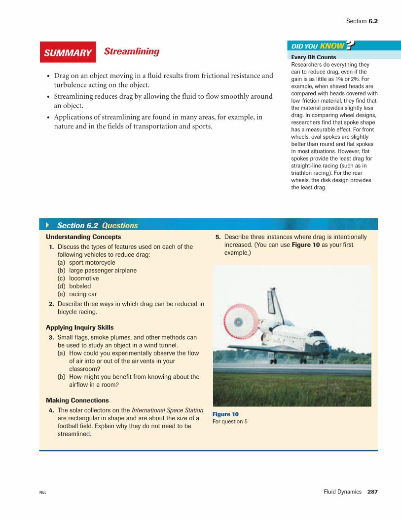
DID YOU KNOW??StreamliningSUMMARY
• Drag on an object moving in a fluid results from frictional resistance and
turbulence acting on the object.
• Streamlining reduces drag by allowing the fluid to flow smoothly around
an object.
• Applications of streamlining are found in many areas, for example, in
nature and in the fields of transportation and sports.
Section 6.2 Questions
Understanding Concepts
1. Discuss the types of features used on each of the
following vehicles to reduce drag:
(a) sport motorcycle
(b) large passenger airplane
(c) locomotive
(d) bobsled
(e) racing car
2. Describe three ways in which drag can be reduced in
bicycle racing.
Applying Inquiry Skills
3. Small flags, smoke plumes, and other methods can
be used to study an object in a wind tunnel.
(a) How could you experimentally observe the flow
of air into or out of the air vents in your
classroom?
(b) How might you benefit from knowing about the
airflow in a room?
Making Connections
4. The solar collectors on the International Space Station
are rectangular in shape and are about the size of a
football field. Explain why they do not need to be
streamlined.
5. Describe three instances where drag is intentionally
increased. (You can use Figure 10 as your first
example.)
Figure 10
For question 5

Fluid Dynamics 291NEL
6.46.4Bernoulli’s Principle
The speed of a moving fluid has an effect on the pressure exerted by the
fluid. Consider water flowing under pressure through the pipe illustrated in
Figure 1. As the water flows from the wide section to the narrow section, its
speed increases. This effect is also seen in rivers that flow slowly through
widely spaced banks but speed up when passing through a narrow gorge.
The effect can be verified experimentally, as you discovered in
Investigation 6.3.
The water flow in Figure 1 accelerates as the water molecules travel from
region A into region B. The acceleration is caused by an unbalanced force,
but what is the source of the acceleration? The answer lies in the pressure
difference between the two regions. The pressure (or force per unit area) must
be greater in region A than in region B in order to accelerate the molecules as
they pass into B.
These concepts were analyzed in detail by the Swiss scientist Daniel
Bernoulli (1700–1782). His conclusions became known as Bernoulli’s
principle.
A device used to demonstrate pressure differences in a fluid at various
speeds is shown in Figure 2. The same conclusions can be drawn from
viewing this apparatus. By comparing the liquid level in the three vertical
columns, we can compare the different speeds of the liquid in the different
parts of the horizontal pipe. (In the diagram, the base of each vertical column
is located at the same level so that the effect of gravity need not be
considered.)
There are many applications of Bernoulli’s principle in technology,
transportation, sports, and other fields. As you read about the examples that
follow, think about how they relate to the activities in Investigation 6.3.
water moves
slowlywater moves
quickly
direction
of flow
A B
Figure 1
The speed of water flowing under
pressure in a pipe depends on the
pipe’s diameter.
Bernoulli’s Principle
Where the speed of a fluid is low, the pressure is high. Where the speed of a fluid
is high, the pressure is low.
slow slow
high pressurehigh pressure
low pressure
pressure indicators
fast
direction of flow
Figure 2
The pressure of the water depends on its speed.

292 Chapter 6 NEL
Consider a paint sprayer (Figure 3). Air from a pump moves rapidly across
the top end of a tube, reducing the pressure in the tube. Atmospheric pressure
forces the paint up the tube to be mixed with the flowing air, creating a spray.
The upward force, or lift, on an airplane wing can be explained by applying
Newton’s third law of motion and Bernoulli’s principle. An airplane wing
(Figure 4) is flatter on the bottom and more curved on the top. As the wing
moves forward, air deflects off the bottom of the wing. The wing thus exerts a
downward action force on the air, and the air exerts an upward reaction force
on the wing. Furthermore, the speed of the air near the deflection is less than
the speed of the streamlined flow of air over the wing. Thus, the pressure
above the wing is low, and the pressure below the wing is high. The pressure
difference adds to the lift on the wing.
reduced pressureair
reduced pressure
air
deflection of
air off wing
Figure 3
A paint sprayer
Figure 4
An airplane wing
The Physics of Flight
There is more to airplane flight than
lift, as explained by Newton’s third
law of motion and Bernoulli’s
principle. Control components such
as flaps are also needed. These
components are examples of
hydraulic systems; they aid in
takeoff, landing, changing altitude,
and steering the plane.
DID YOU KNOW??
GO www.science.nelson.comTRYTHIS activity Paper Airplanes
You can learn a lot about lift and control in airplane flight by designing and
testing paper airplanes. With your teacher’s permission, create and safely test a
paper airplane.
(a) Compare your design and flight distance with those of other students.
(b) Compare your flight distance with the maximum distance in public, indoor
competitions, which can be greater than 40 m!
Perform the tests in an empty space, aiming the planes away from
observers.
Turbine blades in jet engines, windmills, fans, and so on, apply Bernoulli’s
principle (Figure 5). The blade shape resembles an airplane wing. As the fan
rotates, the air above the more curved part of each blade moves faster than the
air above the flatter part. Thus, the pressure is higher on the flatter side of the
blade, and air is forced to move through the fan in the direction from higher
pressure to lower pressure.Figure 5
Jet engine fan

Fluid Dynamics 293NEL
Some skis used in ski-jumping competitions have flexible rubber extensions
at their rear. As the skier glides through the air, the air above the skis travels
faster than the air below. The result is a higher pressure below the skis than
above, which creates an upward lift on the skis (Figure 6).
Section 6.4
reduced pressure
Figure 6
Ski-jumping
direction of throw
airair
original direction
of throw
curved path
of ball
airair
(a) (b) (c)
Figure 7
(a) A ball thrown without spin is not deflected.
(b) Air is dragged around the surface of a baseball thrown with a spin. In this case, the spin is
clockwise when viewed from above the ball.
(c) Because the speed around a spinning ball is not equal on both sides, the pressure is not
equal. The ball is deflected in the direction of the lower pressure.
Throwing a curveball is also an application of Bernoulli’s principle. In
Figure 7(a), a baseball is thrown in the direction shown. Relative to the ball,
the air is moving backward. When the ball is thrown with a clockwise spin, as
viewed from above, the air near the ball’s surface on the left is dragged along
with the ball in the opposite direction to the main airflow (Figure 7(b)). To
the left of the moving ball, the speed of the air is slow, so the pressure is high.
The ball is forced to curve to the right, following the path shown in
Figure 7(c). Most of the ball’s curve takes place in the last few metres of its
path. This last-minute curve tricks the batter, which is the object of throwing
a curveball.
Curveball Simulation
You can pitch a curveball online
and see the airflow around the
baseball. You can choose from a
few locations, including Mars!
LEARNING TIP
GO www.science.nelson.com

294 Chapter 6 NEL
TRYTHIS activityMeasuring the Speed ofWater
(a) Design and perform an experiment to measure the linear speed of water as it
leaves a horizontal hose of known diameter, as shown in Figure 9(a). (Hint:
Time the collection of a measured volume of water to determine the volume
flow rate, qv, then divide that value by the area of the nozzle. This will give
you the speed. Recall from section 5.2, page 231, that v = }
q
Av}.
(b) Extend the experiment to find the speed of the water jet when the original
fluid pressure is constant but the area of the end of the nozzle is halved, as
shown in Figure 9(b).
(c) Relate what you observed in this activity to Bernoulli’s principle.
Perform this activity outdoors where spills will not cause damage.
(a)
(b)
gasoline
mixture of air
and gasoline
(to engine)
air
reduced
pressure
Figure 8
A carburetor used in a small engine
A carburetor is a device that applies Bernoulli’s principle to control the
air–fuel mixture fed to small engines, like those used in snow blowers and
lawnmowers. (It serves the same function as fuel injectors in cars.) A
carburetor has a barrel in which airflow controls the amount of gasoline sent
to the engine. Figure 8 shows air flowing by the gasoline intake. The fast-
moving air has reduced pressure, so the gasoline, which is under atmospheric
pressure, is forced into the carburetor. There it mixes with the air and goes to
the engine.
Figure 9
(a) Water flow with a low pressure (b) Water flow with a high pressure

Fluid Dynamics 295NEL
Section 6.4
Practice
Understanding Concepts
1. Explain the following statements in terms of Bernoulli’s principle:
(a) A tarp, which covers a dumpster with no top, bulges outward as the
dumpster is towed along a highway.
(b) A fire in a fireplace burns better when the wind is blowing outside.
2. Apply Bernoulli’s principle to explain what you observed in Investigation 6.3,
page 288, Figures 1, 3, 4, 5, and 6.
3. Animals that live underground, such as prairie dogs and gophers, require air
circulation in their burrows. To provide enough circulation, these creatures
make one burrow entrance higher than the other, as shown in Figure 10.
Explain how this design helps increase air circulation.
4. Devices described in the text that apply Bernoulli’s principle to turbine blades
are used in air. List devices with turbine blades that are used in water.
Applying Inquiry Skills
5. (a) In a storm with extremely high winds, what might happen to windows if
all windows and doors are closed tightly? Explain your answer.
(b) How would you test your answer to (a) in a laboratory situation?
Making Connections
6. (a) A baseball (viewed from above) is thrown as indicated in Figure 11.
If the ball is spinning counterclockwise, determine the approximate
direction of the ball’s path. Use diagrams in your explanation.
(b) Research the spit ball. What is it, and why was it banned from baseball?
7. Research the meanings of the golfing terms “slice” and “hook.” What causes
slices and hooks, and what should a golfer do to prevent them?
8. During winter, airplane components are carefully checked for ice buildup
before takeoff. If necessary, de-icing procedures are used (Figure 12).
Explain the dangers of ice buildup on aircraft.
Extension
9. (a) If you performed the Try This Activity titled Measuring the Speed of
Water, page 294, relate your calculations in (a) and (b) from the activity
to the equation of continuity, illustrated in Figure 13. This equation
states that the volume flow rate remains constant or continuous for a
particular flow. Thus,
q1 5 q2 or A1v1 5 A2v2
where A1 is the cross-sectional area of the first pipe or opening,
v1 is the speed of the water in the first pipe or through the first
opening,
A2 is the cross-sectional area of the second pipe or opening, and
v2 is the speed of the water in the second pipe or through the
second opening.
(equation applies to incompressible fluids with constant density only)
(b) Water in a garden hose with a cross-sectional area of 3.4 cm2 is
travelling at 4.5 m/s. Determine the speed of the water coming from
a nozzle with a cross-sectional area of 1.2 cm2 attached to the hose.
(Apply the equation of continuity.)
A1 v1 v2A2
Figure 10
Figure 11
Figure 12
De-icing an airplane
Figure 13
Where the area is large, the speed
is slow; where the area is small, the
speed is fast.
Answer
9. (b) 13 m/s

296 Chapter 6 NEL
• Bernoulli’s principle states that where the speed of a fluid is low, the
pressure is high, and where the speed of a fluid is high, the pressure is
low. This principle is applied in throwing a curveball and in many other
situations.
Bernoulli’s PrincipleSUMMARY
Section 6.4 Questions
Understanding Concepts
1. It is unwise to stand close to a fast-moving
subway train. Explain why in terms of
Bernoulli’s principle.
2. Figure 14 shows a device called a Venturi
flowmeter, used to measure the speed of
gas flowing through a tube. Explain how
its design relates to Bernoulli’s principle.
3. Imagine you are able to test your
throwing skills in a large laboratory
with all its air removed. You are given a
table-tennis ball and a Frisbee to throw.
You find that the table-tennis ball goes much farther
than it does in a room with air, but the Frisbee flies
comparatively poorly. Explain these observations.
Applying Inquiry Skills
4. Explain how you would use a manometer as a meter
to measure the flow rate of moving air. (The mano-
meter was described in section 5.3, page 241.)
Making Connections
5. A spoiler on the rear of a car (Figure 15) has a
cross-sectional shape that resembles an airplane
wing.
(a) Does the spoiler shown result in an upward or
downward force on the rear of the moving car?
Explain your answer.
(b) To help keep a car stable when travelling around
curves, which way should the spoiler be
installed? Explain your answer.
(c) Some spoilers are designed just for appearance
(i.e., they provide none of the advantages that
spoilers on racing cars provide). Describe the
disadvantage of having this type of spoiler.
6. Windsurfing boards are designed for maximum
speed and stability in a variety of wind conditions.
However, the problems created by high winds are
different from problems created by low winds.
Research windsurfing boards, and find out how the
vented nose on the board reduces the tendency of
the board to lift off and “tail walk” in high winds.
flow of gas
mercury
Figure 14
A Venturi flowmeter
Figure 15
GO www.science.nelson.com