Embed Size (px)
Citation preview
SEMESTER-6 ELECTRICAL & ELECTRONICS ENGINEERING
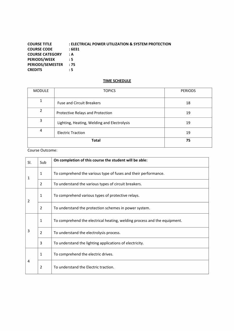
COURSE TITLE : ELECTRICAL POWER UTILIZATION & SYSTEM PROTECTION COURSE CODE : 6031 COURSE CATEGORY : A PERIODS/WEEK : 5 PERIODS/SEMESTER : 75 CREDITS : 5
TIME SCHEDULE
MODULE TOPICS PERIODS
1 Fuse and Circuit Breakers 18
2 Protective Relays and Protection 19
3 Lighting, Heating, Welding and Electrolysis 19
4 Electric Traction 19
Total 75
Course Outcome:
Sl. Sub On completion of this course the student will be able:
1 1 To comprehend the various type of fuses and their performance.
2 To understand the various types of circuit breakers.
2 1 To comprehend various types of protective relays.
2 To understand the protection schemes in power system.
3
1 To comprehend the electrical heating, welding process and the equipment.
2 To understand the electrolysis process.
3 To understand the lighting applications of electricity.
4
1 To comprehend the electric drives.
2 To understand the Electric traction.
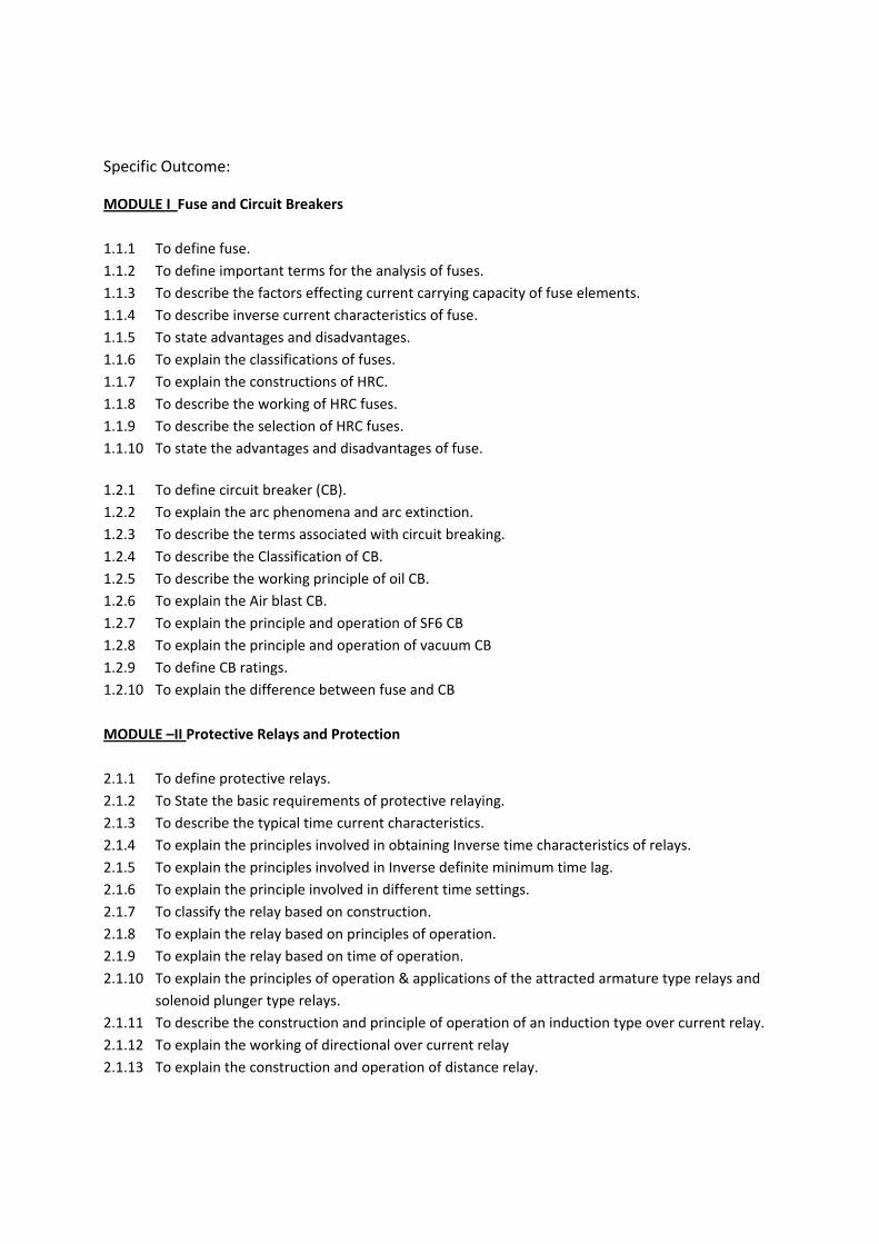
Specific Outcome:
MODULE I Fuse and Circuit Breakers
1.1.1 To define fuse. 1.1.2 To define important terms for the analysis of fuses. 1.1.3 To describe the factors effecting current carrying capacity of fuse elements. 1.1.4 To describe inverse current characteristics of fuse. 1.1.5 To state advantages and disadvantages. 1.1.6 To explain the classifications of fuses. 1.1.7 To explain the constructions of HRC. 1.1.8 To describe the working of HRC fuses. 1.1.9 To describe the selection of HRC fuses. 1.1.10 To state the advantages and disadvantages of fuse.
1.2.1 To define circuit breaker (CB). 1.2.2 To explain the arc phenomena and arc extinction. 1.2.3 To describe the terms associated with circuit breaking. 1.2.4 To describe the Classification of CB. 1.2.5 To describe the working principle of oil CB. 1.2.6 To explain the Air blast CB. 1.2.7 To explain the principle and operation of SF6 CB 1.2.8 To explain the principle and operation of vacuum CB 1.2.9 To define CB ratings. 1.2.10 To explain the difference between fuse and CB MODULE –II Protective Relays and Protection
2.1.1 To define protective relays. 2.1.2 To State the basic requirements of protective relaying. 2.1.3 To describe the typical time current characteristics. 2.1.4 To explain the principles involved in obtaining Inverse time characteristics of relays. 2.1.5 To explain the principles involved in Inverse definite minimum time lag. 2.1.6 To explain the principle involved in different time settings. 2.1.7 To classify the relay based on construction. 2.1.8 To explain the relay based on principles of operation. 2.1.9 To explain the relay based on time of operation. 2.1.10 To explain the principles of operation & applications of the attracted armature type relays and
solenoid plunger type relays. 2.1.11 To describe the construction and principle of operation of an induction type over current relay. 2.1.12 To explain the working of directional over current relay 2.1.13 To explain the construction and operation of distance relay.

2.2.1 To explain the primary and back up protection. 2.2.2 To explain the differential protection of alternators. 2.2.3 To explain the earth leakage protection of alternators. 2.2.4 To explain the Merz - Prize protection of 3 phase transformers. 2.2.5 To describe the working of Buchholz relay. 2.2.6 To describe the Protection of bus bars. 2.2.7 To explain the various protections of transmission lines. 2.2.8 To explain the apparatus used in power stations and sub stations. 2.2.9 To explain the protection by ground wires. 2.2.10 To describe different protection methods used against lightning. 2.2.11 To explain operation of the Lightning arrester. 2.2.12 To describe thyrite types lightning arresters. 2.2.13 To State the soil resistivity. 2.2.14 To explain how the soil resistivity is measured. 2.2.15 To explain different methods of neutral earthing MODULE III Lighting, Heating, Welding and Electrolysis
3.1.1 To state modes of heat transfer 3.1.2 To list the advantages of electric heating 3.1.3 To list the requirements of good heating material 3.1.4 To explain with sketches
i. Direct resistance heating ii. Indirect resistance heating
3.1.5 To state the Industrial application of the direct & indirect resistance heating. 3.1.6 To explain direct arc furnace & indirect arc furnace with diagram. 3.1.7 To explain the principle of operations of low and high frequency induction furnaces. 3.1.8 To explain the principle of operations of core type and core less type induction furnaces. 3.1.9 To explain the principle of dielectric heating. 3.1.10 To list the industrial applications of the dielectric heating. 3.1.11 To state different types of Electric welding. 3.1.12 To explain the principles and applications of a) Spot b) Seam c) butt welding. 3.1.13 To explain the characteristics of a welding generator. 3.1.14 To explain with sketch the principle of operation of welding transformer used with a reactance
coil.
3.2.1 To describe the process of electrolysis. 3.2.2 To state the Faraday’s laws of electrolysis. 3.2.3 To explain the field of applications of electrolysis. 3.2.4 To understand the lighting applications of electricity. 3.2.5 To explain the main lighting loads.
3.2.6 To describe the main objects of street lighting. 3.2.7 To explain the various flood lighting schemes. 3.2.8 To compute simple problems. MODULE IV Electric Traction
4.1.1 To state the advantage of Electric drives. 4.1.2 To list the factors governing the selection of motors. 4.1.3 To classify the electric drives. 4.1.4 To state the advantages and disadvantages of group drive. 4.1.5 To state the advantages and disadvantages of individual drive.
4.2.1 To explain different systems of traction. 4.2.2 To state the advantages of electric traction. 4.2.3 To state the importance of the speed time curves. 4.2.4 To state each stage of the speed time curve. 4.2.5 To sketch the simplified speed time curve and derive the relation. 4.2.6 To explain the Practical importance of the above curves. 4.2.7 To solve the simple problems using speed time curves. 4.2.8 To explain the meaning of traction effort. 4.2.9 To explain the term specific energy consumption. 4.2.10 To derive the formula for energy output of drive axles in accelerations;
i. To overcome friction. ii. To overcome gradient.
4.2.11 To list the factors affecting specific energy consumption. 4.2.12 To state the important requirements of traction motor. 4.2.13 To explain the suitability of motors for electric traction DC series motor or series motor. 4.2.14 To state the advantages of electric braking. 4.2.15 To explain the methods of electric braking;
i. Plugging. ii. Regenerative. iii. Rheostatic.
4.2.16 To state the method of regenerative braking of DC shunt motor, DC series motor and 3-phase induction motor.
4.2.17 To explain the method of Rheostatic braking on DC shunt motor and series motor
CONTENTS
MODULE – I
Definition of fuse- important terms- current rating of fuse elements- fusing current- fusing factor- prospective current –cut off current- pre arcing time-arcing time- total operating time- breaking
capacity- current carrying capacity factors. Inverse current characteristics- advantages and disadvantages of fuse – types of fuses- low voltage fuses- high voltage fuses - HRC fuse- construction- working- selection for various applications-advantages and disadvantages. Circuit breakers definition- arc phenomenon-arc extinction- methods of arc extinction - high resistance method- low resistance method - Important terms – arc voltage - restriking voltage - recovery voltage—RRRV-current chopping. Classification of CB – OCB – ABCB (axial blast and cross blast) - SF6 – VCB – working and applications. CB rating – breaking capacity - making capacity - short time rating - difference between fuse and C B.
MODULE- II
Bus–bar protection- different protection- fault bus protection - protection of lines- time graded over current protection- differential protection-distance protection. Protection against over voltage - voltage surge- causes of over voltages (internal of external causes). Lightning – protection against lightning-lightning arresters - rod gap arresters - horn gap arresters - surge absorber- neutral grounding- equipment grounding- advantages of neutral grounding- methods of neutral grounding- solid grounding - resistance grounding- reactance grounding- voltage transformer earthing.
MODULE- III
Modes of heat transfer- conduction- convection – radiation – examples- advantages of electric heating- requirement of good heating element- different types of electrical heating (direct resistance or indirect resistance). Applications of induction furnace- (low and high frequency- application of core and coreless – dielectric heating- application of dielectric welding –application and working - spot- seam - butt – electrical characteristics of welding generator- electrolysis- low and application - Lighting loads - street light - flood lights - problems.
MODULE- IV
Electric drive definitions- components of electric drive- block diagram- advantages- selection of drive- - factors governing the selection of motor- nature of drive- group drive- industrial drive- applications- advantages and disadvantages. Traction definition- different types of traction- electric supply for traction- speed time curve- importance of speed time curve- comparison- main line service- urban- sub urban service- different terms- average speed- scheduled speed- crest speed- simplification of speed time curve - simple problems - traction effort- specific energy consumption - derivation- energy output at drive axles- friction and gradient.
REFERENCE:
1. J B Gupta. A course in Power systems: S K Kataria & sons. 2. Suryanarayanan N V. Utilization of electric power: new age international publishers
ltd. 3. V K Metha. Power system protection: Khanna Publishers
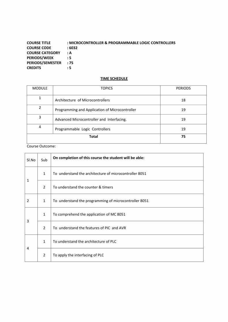
COURSE TITLE : MICROCONTROLLER & PROGRAMMABLE LOGIC CONTROLLERS COURSE CODE : 6032 COURSE CATEGORY : A PERIODS/WEEK : 5 PERIODS/SEMESTER : 75 CREDITS : 5
TIME SCHEDULE
MODULE TOPICS PERIODS
1 Architecture of Microcontrollers 18
2 Programming and Application of Microcontroller 19
3 Advanced Microcontroller and Interfacing. 19
4 Programmable Logic Controllers 19
Total 75
Course Outcome:
Sl.No Sub On completion of this course the student will be able:
1
1 To understand the architecture of microcontroller 8051
2 To understand the counter & timers
2 1 To understand the programming of microcontroller 8051
3
1 To comprehend the application of MC 8051
2 To understand the features of PIC and AVR
4
1 To understand the architecture of PLC
2 To apply the interfacing of PLC
Specific Outcome:
MODULE I Architecture of Microcontrollers
1.1.1 To introduce 8051 micro controller. 1.1.2 To describe feature of 8051. 1.1.3 To describe block diagram of 8051. 1.1.4 To describe 8051 architecture. 1.1.5 To explain register structure of 8051. 1.1.6 To explain special function register of 8051. 1.1.7 To describe internal & external memory of 8051. 1.1.8 To describe pin details of 8051. 1.1.9 To describe ports of 8051.
1.2.1 To explain counters& timers in 8051 and associated registers-TMOD,TCON. 1.2.2 To describe modes of operation of timers / counters. 1.2.3 To explain serial input/output of 8051 and associated registers-SCON,SBUF. 1.2.4 To Explain interrupts in 8051 and associated registers-IP,IE. MODULE II Programming and Application of Microcontroller
2.1.1 To explain addressing modes of 8051. 2.1.2 To describe instruction set of 8051. 2.1.3 To describe logical operations. 2.1.4 To describe arithmetic operations. 2.1.5 To describe jump and call instructions. 2.1.6 To describe timing & delay subroutines MODULE III Advanced Microcontroller and Interfacing. 3.1.0 To describe the basics of serial communication. 3.1.1 To describe the asynchronous serial communication and data framing. 3.1.2 To explain serial communication between PC and 8051. 3.1.3 To describe 8255 programmable peripheral interface 3.1.4 To demonstrate controlling of a stepper motor with µC 8051. 3.1.5 To describe how to interface a relay with µC 8051. 3.2.0 To explain the features of PIC 18. 1.2.1 To explain the block diagrams of ;
a) PIC18. b) PIC 16.
To describe PIC architecture.
3.2.0 To explain the features of AVR. 3.2.1 To explain the block diagram of AT tiny 25. 3.2.2 To explain the block diagram of AT mega 32. 3.2.3 To describe AVR architecture. MODULE IV Programmable Logic Controllers
4.1.0 To explain the Applications & Importance of PLC. 4.1.1 To compare PLC and a relay panel. 4.1.2 To classify PLC. 4.1.3 To describe the block diagram and operation of a micro PLC. 4.1.4 To classify PLC programming. 4.1.5 To give an idea of ladder programming. 4.1.6 To describe timer / counter instruction sets.
4.2.0 To describe math and logical instructions. 4.2.0 To study the Ladder programming. 4.2.1 To list the types of Instructions. 4.2.2 To explain how to select a PLC for a typical application. 4.2.3 To explain how to interface an induction motor using PLC. 4.2.4 To explain how to interface a traffic control with PLC.
CONTENTS
MODULE - I
Introduction. Architecture of microcontroller - microcontroller-evolution of microprocessor-microcontroller-microcontroller family. The 8051 microcontroller- features – architecture of 8051 – block diagram. Memory organization – Program memory – data memory – internal and external memory-Internal DATA memory structure –register banks – bit addressable area – scratch pad area-stock area- memory addresses- special function registers – accumulator-B register-DPTR-SP-Program Status Word – Flags –other SFRs-selection of register bank - Internal programme memory - capacity-address range - provision for external data memory - address range - provision for external programme memory-address range - external memory access-use of address latch. Pin configuration of 8051-description of eh pins-Ports in 8051 – port addresses - making ports as input and output ports -timers and counters in 8051 - timer registers - TMOD register-TCON register - different modes. Frequency of internal clock signal - machine cycle - calculation of time delay. Interrupts in 8051-need - IE register - IP register - interrupt vector table.
MODULE - II
Programming and application of microcontroller - the 8051 instruction set-classification-data transfer instructions-arithmetic instructions-logical instructions-branching and control transfer instructions-use of each instruction. Arithmetic and logical operations - Subroutines – interrupt service routine-need of subprograms-calling a subprogram-ACALL-LCALL- examples. Data transfer in 8051-addressing modes. Simple Programmes - arithmetic operations-block transfer of data - array sorting-time delay using sub routines.
MODULE - III Advanced microcontrollers & interfacing. Serial communication –basic principles-baud rate-asynchronous and synchronous communication- data framing-8051 registers related to serial communication-SBUF-SCON-serial communication ports. Microcontroller based system-peripherals-interfacing peripherals - 8255 programmable peripheral interface –need-block diagram-control word Register - Interfacing of stepper motor and relays. Features of PIC 18 - block diagram - block diagram of PIC 16 - architecture. Features of AVR- 25 block diagram of AT tiny 25 - block diagram of AT mega 32.- AVR architecture. MODULE – IV Programmable Logic Controllers. PLC- Applications, Importance, classification, Comparison of PLC with Relay panel, block diagram and Operation of PLC. Classifiation of PLC programming- Ladder programming.Types of Instructions bit instructions- timer/counter instructions , Logical, compare instructions, move instructions - math instructions, programme control instructions - simple ladder programs connecting the above Instructions – motor control using PLC.
REFERANCES:
1. V Udayashankara & M S Mallikarjunaswamy. 8051 Microcontroller : Hardware , Software and Applications: Tata Mc Graw-hill Publishing company.
2. Kenneth J. Ayala. The 8051 Microcontroller: Thomson Delmer Learning. 3. Mazidi Muhammad Ali. The 8051 Microcontroller and Embedded Systems: Using Assembly and
C: Pearson Education. 4. N. Senthil Kumar. Microprocessors and Microcontrollers: OUP India. 5. Muhammed Ali Mazeedi, Rolin D McKinlay & Danny Causey. PIC Microcontroller and Embedded
Systems: Using Assembly and C Pearson Prentice Hall. 6. Muhammed Ali Mazeedi . AVR Microcontroller and Embedded Systems: Pearson Education Ltd.
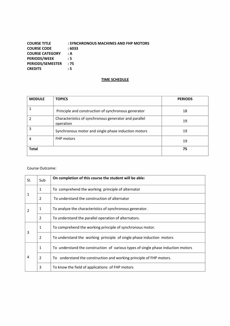
COURSE TITLE : SYNCHRONOUS MACHINES AND FHP MOTORS COURSE CODE : 6033 COURSE CATEGORY : A PERIODS/WEEK : 5 PERIODS/SEMESTER : 75 CREDITS : 5
TIME SCHEDULE
MODULE TOPICS PERIODS
1 Principle and construction of synchronous generator 18
2 Characteristics of synchronous generator and parallel operation
19
3 Synchronous motor and single phase induction motors 19
4 FHP motors
19
Total 75
Course Outcome:
Sl. Sub On completion of this course the student will be able:
1 1 To comprehend the working principle of alternator
2 To understand the construction of alternator
2 1 To analyze the characteristics of synchronous generator.
2 To understand the parallel operation of alternators.
3 1 To comprehend the working principle of synchronous motor.
2 To understand the working principle of single phase induction motors
4
1 To understand the construction of various types of single phase induction motors
2 To understand the construction and working principle of FHP motors.
3 To know the field of applications of FHP motors
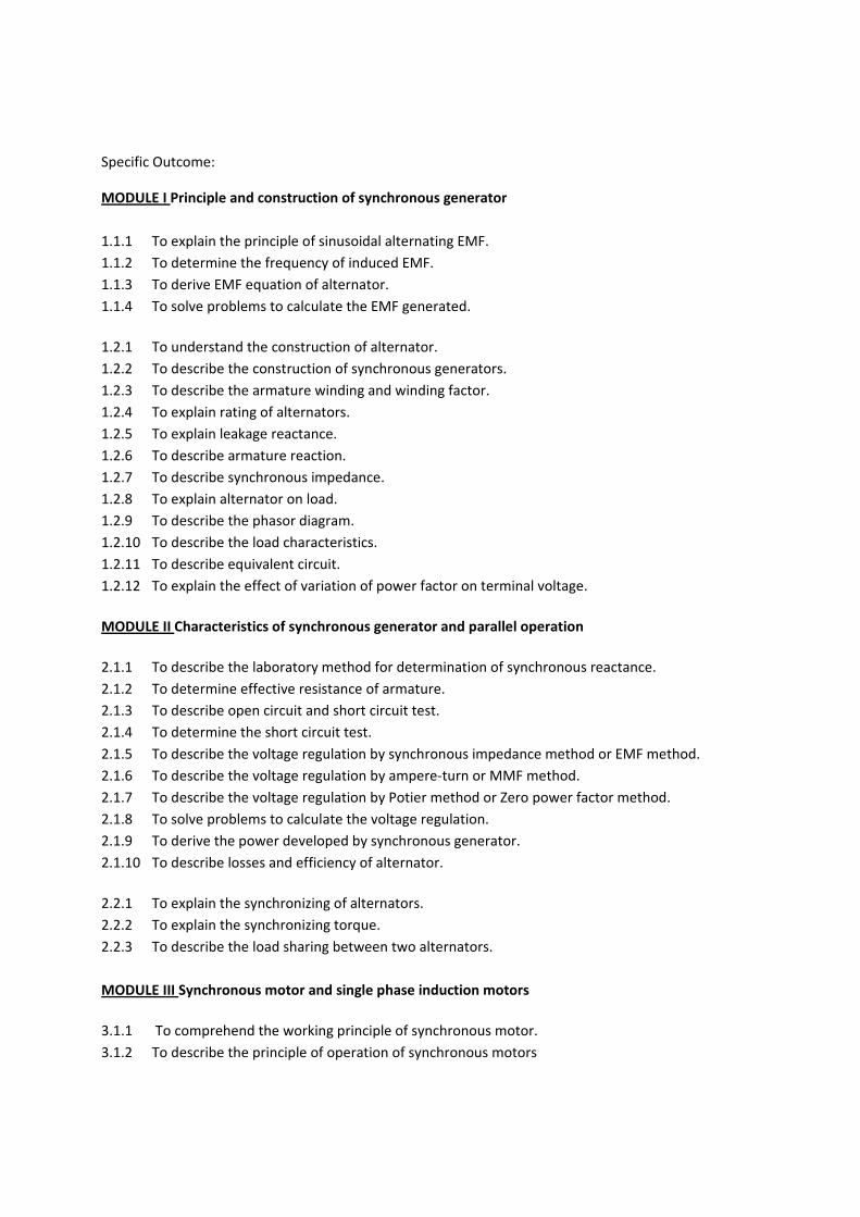
Specific Outcome:
MODULE I Principle and construction of synchronous generator
1.1.1 To explain the principle of sinusoidal alternating EMF. 1.1.2 To determine the frequency of induced EMF. 1.1.3 To derive EMF equation of alternator. 1.1.4 To solve problems to calculate the EMF generated.
1.2.1 To understand the construction of alternator. 1.2.2 To describe the construction of synchronous generators. 1.2.3 To describe the armature winding and winding factor. 1.2.4 To explain rating of alternators. 1.2.5 To explain leakage reactance. 1.2.6 To describe armature reaction. 1.2.7 To describe synchronous impedance. 1.2.8 To explain alternator on load. 1.2.9 To describe the phasor diagram. 1.2.10 To describe the load characteristics. 1.2.11 To describe equivalent circuit. 1.2.12 To explain the effect of variation of power factor on terminal voltage. MODULE II Characteristics of synchronous generator and parallel operation
2.1.1 To describe the laboratory method for determination of synchronous reactance. 2.1.2 To determine effective resistance of armature. 2.1.3 To describe open circuit and short circuit test. 2.1.4 To determine the short circuit test. 2.1.5 To describe the voltage regulation by synchronous impedance method or EMF method. 2.1.6 To describe the voltage regulation by ampere-turn or MMF method. 2.1.7 To describe the voltage regulation by Potier method or Zero power factor method. 2.1.8 To solve problems to calculate the voltage regulation. 2.1.9 To derive the power developed by synchronous generator. 2.1.10 To describe losses and efficiency of alternator.
2.2.1 To explain the synchronizing of alternators. 2.2.2 To explain the synchronizing torque. 2.2.3 To describe the load sharing between two alternators. MODULE III Synchronous motor and single phase induction motors
3.1.1 To comprehend the working principle of synchronous motor. 3.1.2 To describe the principle of operation of synchronous motors
3.1.3 To describe the load on a synchronous motor 3.1.4 To describe effects of varying excitation on armature current and power factor of synchronous
motors 3.1.5 T o explain the equivalent circuit, phasor diagram of synchronous motor 3.1.6 To describe the power developed in a synchronous motor 3.1.7 To describe the power flow in a synchronous motor 3.1.8 To describe the different torques of a synchronous motor 3.1.9 To describe V and inverted V curves of synchronous motor 3.1.10 To describe main characteristics of synchronous motor 3.1.11 To describe synchronous condenser 3.1.12 To describe the starting method of synchronous motors 3.1.13 To explain the application of synchronous motors 3.1.14 To describe the production of two phase rotating magnetic field 3.1.15 To describe the classification of single phase induction motors 3.1.16 To explain why single phase induction motor is not self starting MODULE IV FHP motors
4.1.0 To understand the construction of various types of single phase induction motors. 4.1.1 To describe the starting methods and types of single phase induction motors. 4.1.2 To explain resistance start single phase induction motors. 4.1.3 To describe capacitor start single phase induction motors. 4.1.4 To explain capacitor start capacitor run single phase induction motors. 4.1.5 To describe permanent capacitor single phase induction motors. 4.1.6 To explain the speed control of single phase induction motors. 4.2.0 To understand the construction and working principle of FHP motors. 4.2.1 To explain the working of shaded pole motor. 4.2.2 To describe commutator motors. 4.2.3 To describe series motors. 4.2.4 To explain the working of Universal motors. 4.2.5 To describe Repulsion type motors. 4.2.6 To compare the methods for starting of single phase induction motors. 4.2.7 To describe servo motors. 4.2.8 To describe stepper motors. 4.2.9 To describe switched reluctance motors. 4.2.10 To describe printed circuit board motors. 4.3.0 To know the field of applications of FHP motors. 4.3.1 To explain the applications of FHP motors.
CONTENT DETAILS
MODULE – I
Alternator - constructional details - generation of sinusoidal EMF – frequency - Armature winding - different types - distribution factor – chording factor – simple problems - E MF equation – problems - rating of alternator - Armature reaction - effect of pf – synchronous impedance - alternator on load- phasor diagrams - problems.
MODULE – II
Regulation of alternator – definition - Testing of alternator - open circuit test - short circuit test - predetermination of synchronous reactance - regulation by EMF method – MMF method – ZPF method – problems - Direct load test – regulation – problems - Losses and efficiency - Synchronizing of alternator – characteristics - Synchronizing power and torque - load sharing.
MODULE –III
Synchronous motor – construction – principle of operation – method of starting – effect of changing excitation on armature current and power factor – vector diagram synchronous condenser - V- curves and inverted V curves - Power developed - different torques – problems - Applications – comparison between synchronous motor and induction motor.
MODULE –IV
Single phase induction motor – double revolving field theory - classification – split phase motor – capacitor start motor – capacitor start and capacitor run – shaded pole motor – speed control of single phase induction motor (voltage control) -Commutator motor – series motor – repulsion motor – servo motors – stepper motors – single phase synchronous motors - Switched reluctance motor – printed circuit board motors.
REFERENCES:
1. BL Theraja. Electrical technology. Vol- II: S Chand & co. 2. JB Gupta. Theory and performance of electrical Machines: S. K. Kataria & Sons
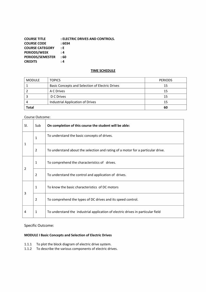
COURSE TITLE : ELECTRIC DRIVES AND CONTROLS. COURSE CODE : 6034 COURSE CATEGORY : E PERIODS/WEEK : 4 PERIODS/SEMESTER : 60 CREDITS : 4
TIME SCHEDULE
MODULE TOPICS PERIODS
1 Basic Concepts and Selection of Electric Drives 15
2 A C Drives 15
3 D C Drives 15
4 Industrial Application of Drives 15
Total 60 Course Outcome:
Sl. Sub On completion of this course the student will be able:
1
1 To understand the basic concepts of drives.
2 To understand about the selection and rating of a motor for a particular drive.
2
1 To comprehend the characteristics of drives.
2 To understand the control and application of drives.
3
1 To know the basic characteristics of DC motors
2 To comprehend the types of DC drives and its speed control.
4 1 To understand the industrial application of electric drives in particular field
Specific Outcome: MODULE I Basic Concepts and Selection of Electric Drives
1.1.1 To plot the block diagram of electric drive system. 1.1.2 To describe the various components of electric drives.
1.1.3 To compare electric drives and mechanical drives. 1.1.4 To discriminate the different factors for the choice of electric drives. 1.1.5 To describe the classification of electric drives with specific application. 1.1.6 To describe the advantages of electric drives. 1.1.7 To describe factors affecting the size and rating of motor for a particular application. 1.1.8 To understand the status of electric drives.
1.2.1 To determine the power rating motor for continuous operation at constant speed drives like
linear motion, lifts, pumps and fans. MODULE II A C Drives
2.1.1 To analyze the performance characteristics of the three phase induction motors. 2.1.2 To describe the different methods of starting of three phase induction motors. 2.1.3 To describe the different methods of braking of induction motors. 2.1.4 To categorize different methods of speed control of three phase induction motors.
2.2.1 To describe speed control by voltage controllers. 2.2.2 To describe variable frequency control from voltage sources. 2.2.3 To describe variable frequency control from current sources. 2.2.4 To discriminate current source inverter and voltage source inverter drives. 2.2.5 To describe speed control by voltage source inverter. 2.2.6 To describe speed control by cycloconverter. 2.2.7 To describe speed control of single phase induction motors by voltage controllers. 2.2.8 To describe speed control of synchronous motor from variable frequency. 2.2.9 To analyze the operation of self controlled synchronous motor drive. 2.2.10 To describe the permanent magnet synchronous motor drives.
MODULE III D C Drives
3.1.1 To analyze the basic characteristics of various types of DC motors. 3.1.2 To describe the different methods of starting of DC motors. 3.1.3 To describe the different methods of braking of DC motors. 3.2.1 To categorize different methods of speed control of DC motors. 3.2.2 To describe speed control by armature voltage control and flux control. 3.2.3 To describe speed control by transformer and uncontrolled rectifier fed DC drives. 3.2.4 To describe speed control by controlled rectifier fed DC drives. 3.2.5 To describe chopper controlled DC drives. 3.2.6 To analyze the conventional and DC traction drives. 3.2.7 To analyze the operation of DC traction using chopper controlled DC motor drives. MODULE IV Industrial Application of Drives
4.1.1 To describe the working of;
a) Solar powered pump drives b) Battery powered vehicle drives
4.1.2 To describe the electric drives in;
a) Steel mills. b) Paper mill. c) Cement mills. d) Textile mills. e) Sugar mills. f) Petrochemical industry. g) Coal mining.
CONTENTS
MODULE I Electric drive – block diagram - explanation of each block - electric drive and mechanical drive –comparison. Factors for the choice of electric drives. Advantages. Classification. Size and rating of motors - determination of rating of motor – linear motion-lifts-pumps-and fans. MODULE II Performance characteristics of 3 phase induction motors-staring – braking. Speed control-voltage controllers-variable frequency from voltage source-current sources - cyclo converter - current source and voltage source- inverter fed drive- Comparison. Speed control - single phase induction motor by voltage controllers - synchronous motor from variable frequency – self controlled synchronous motor drive-permanent magnet synchronous motor drive. MODULE III Performance characteristics of DC motors-staring –braking .speed control. Uncontrolled rectifier fed drive- controlled rectifier fed drive - chopper controlled DC motor-DC traction drive - Chopper controlled traction drive. MODULE IV Solar powered pump drive - battery powered vehicle drive - Selection of drives in – steel mills - paper mills - cement mills - textile mills-sugar mills - petrochemical industry – coal mining.\ TEXT BOOKS
1. Gopal K Dubbey. Fundamentals of electric drives: Narosa publishing house 2. S K Pillai. A first course on electrical Drives: Wiley Eastern limited
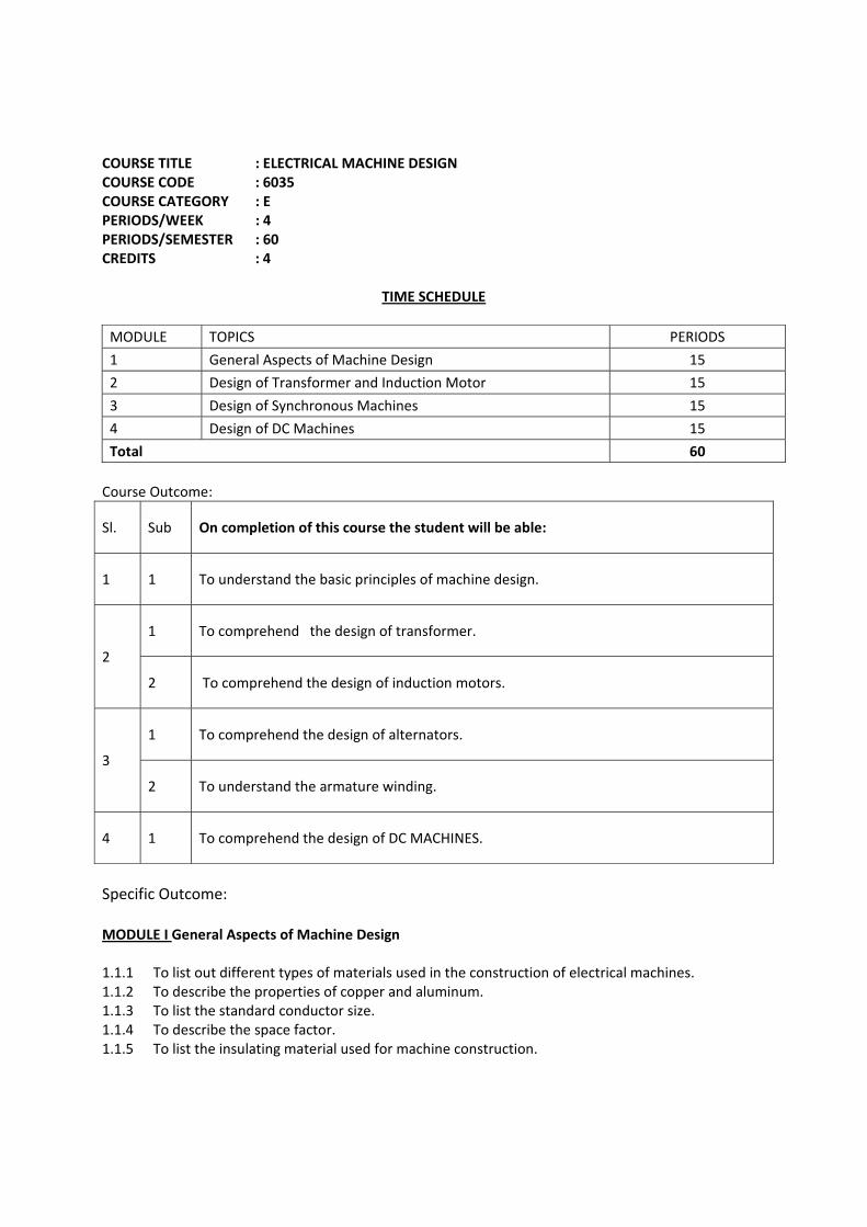
COURSE TITLE : ELECTRICAL MACHINE DESIGN COURSE CODE : 6035 COURSE CATEGORY : E PERIODS/WEEK : 4 PERIODS/SEMESTER : 60 CREDITS : 4
TIME SCHEDULE
MODULE TOPICS PERIODS
1 General Aspects of Machine Design 15
2 Design of Transformer and Induction Motor 15
3 Design of Synchronous Machines 15
4 Design of DC Machines 15
Total 60 Course Outcome:
Sl. Sub On completion of this course the student will be able:
1 1 To understand the basic principles of machine design.
2
1 To comprehend the design of transformer.
2 To comprehend the design of induction motors.
3
1 To comprehend the design of alternators.
2 To understand the armature winding.
4 1 To comprehend the design of DC MACHINES.
Specific Outcome: MODULE I General Aspects of Machine Design
1.1.1 To list out different types of materials used in the construction of electrical machines. 1.1.2 To describe the properties of copper and aluminum. 1.1.3 To list the standard conductor size. 1.1.4 To describe the space factor. 1.1.5 To list the insulating material used for machine construction.
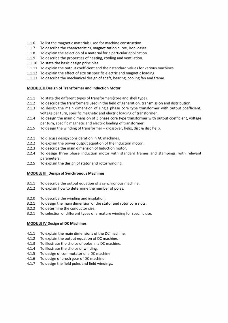
1.1.6 To list the magnetic materials used for machine construction 1.1.7 To describe the characteristics, magnetization curve, iron losses. 1.1.8 To explain the selection of a material for a particular application. 1.1.9 To describe the properties of heating, cooling and ventilation. 1.1.10 To state the basic design principles. 1.1.11 To explain the output coefficient and their standard values for various machines. 1.1.12 To explain the effect of size on specific electric and magnetic loading. 1.1.13 To describe the mechanical design of shaft, bearing, cooling fan and frame. MODULE II Design of Transformer and Induction Motor
2.1.1 To state the different types of transformers(core and shell type). 2.1.2 To describe the transformers used in the field of generation, transmission and distribution. 2.1.3 To design the main dimension of single phase core type transformer with output coefficient,
voltage per turn, specific magnetic and electric loading of transformer. 2.1.4 To design the main dimension of 3 phase core type transformer with output coefficient, voltage
per turn, specific magnetic and electric loading of transformer. 2.1.5 To design the winding of transformer – crossover, helix, disc & disc helix.
2.2.1 To discuss design consideration in AC machines. 2.2.2 To explain the power output equation of the Induction motor. 2.2.3 To describe the main dimension of Induction motor. 2.2.4 To design three phase induction motor with standard frames and stampings, with relevant
parameters. 2.2.5 To explain the design of stator and rotor winding. MODULE III: Design of Synchronous Machines
3.1.1 To describe the output equation of a synchronous machine. 3.1.2 To explain how to determine the number of poles.
3.2.0 To describe the winding and insulation. 3.2.1 To design the main dimension of the stator and rotor core slots. 3.2.2 To determine the conductor size. 3.2.1 To selection of different types of armature winding for specific use.
MODULE IV Design of DC Machines
4.1.1 To explain the main dimensions of the DC machine. 4.1.2 To explain the output equation of DC machine. 4.1.3 To illustrate the choice of poles in a DC machine. 4.1.4 To illustrate the choice of winding. 4.1.5 To design of commutator of a DC machine. 4.1.6 To design of brush gear of DC machine. 4.1.7 To design the field poles and field windings.

CONTENTS
MODULE – I Basic concepts of machine design- materials used for construction – properties and characteristics of magnetic materials - conducting materials and insulating materials- selection of materials. Heating and cooling - basic design principles – output coefficient – specific electric loading – specific magnetic loading – problems. Mechanical design - shaft- bearing – cooling fan – frame. MODULE-II Design of induction machines – transformers – different types – design of main dimensions of single phase core type transformers – problems - design of main dimensions of three phase core type transformers - problems - design of transformer winding - induction motor- design considerations - output equation - main dimensions - design of three phase induction motor – problems. MODULE –III Synchronous machines - output equations - choice of specific magnetic loading - specific electric loading - main dimensions - armature design – armature winding – design of magnetic circuit - problems. MODULE IV Design of DC machines - main dimensions – output equations - design of magnetic circuits – field poles and field windings - design of armature winding – commutator and brush. REFERENCES
1. AK Sawhney. A course in electrical machine design: Danpat Rai &co. 2. K G Upadhyay. Design of electrical achiness: New age International.
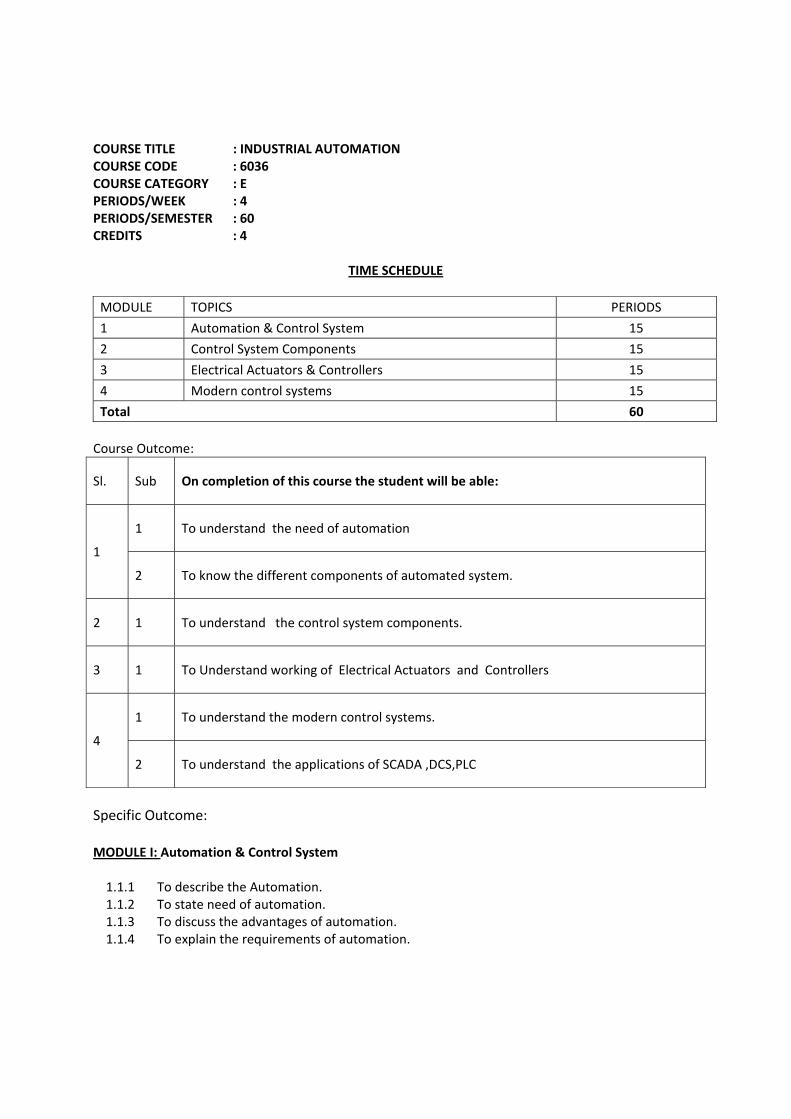
COURSE TITLE : INDUSTRIAL AUTOMATION COURSE CODE : 6036 COURSE CATEGORY : E PERIODS/WEEK : 4 PERIODS/SEMESTER : 60 CREDITS : 4
TIME SCHEDULE
MODULE TOPICS PERIODS
1 Automation & Control System 15
2 Control System Components 15
3 Electrical Actuators & Controllers 15
4 Modern control systems 15
Total 60 Course Outcome:
Sl. Sub On completion of this course the student will be able:
1
1 To understand the need of automation
2 To know the different components of automated system.
2 1 To understand the control system components.
3 1 To Understand working of Electrical Actuators and Controllers
4
1 To understand the modern control systems.
2 To understand the applications of SCADA ,DCS,PLC
Specific Outcome: MODULE I: Automation & Control System 1.1.1 To describe the Automation. 1.1.2 To state need of automation. 1.1.3 To discuss the advantages of automation. 1.1.4 To explain the requirements of automation.
1.2.1 To explain the concept of control system. 1.2.2 To explain the open loop-closed loop control system. 1.2.3 To draw basic block diagram of control system. 1.2.4. To state the different terms in control system. 1.2.5. To explain applications of control system. 1.2.6 To develop the block diagram for simple control applications.
MODULE II: Control System Components 1.1.1 To describe the different types of contacts. 1.1.2 To describe current capacity & load utilization categories. 1.1.3 To discuss various types of DC, AC solenoids. 1.1.4 To explain various input devices. 1.1.5 To explain different output devices- contactors, valves, pilot lamps 1.1.6 To draw symbols in power & control circuits. 1.1.7 To develop a basic control circuit using above components. 1.1.8 To describe power & control circuit for different applications.
MODULE III: Electrical Actuators & Controllers
3.1.1. To explain potentiometers working as an error detector. 3.1.2. To describe the working principle of AC servomotor. 3.1.3 To describe the working principle of DC servomotors. 3.1.4 To explain synchros - transmitter, control transformer. 3.1.5 To describe the working of stepper motor-PM , variable reluctance & Tacho-generator. 3.1.6 To state applications of various components as AC/DC control system. 3.1.7 To explain the functions of control valves 3.1.8 To describe the working of Pneumatic control elements. 3.1.9 To explain the functions electrical controllers. 3.1.10 To explain the functions Electronic controllers. 3.1.11 To explain digital controllers.
MODULE IV: Modern control systems 4.1.1 To explain various control actions. 4.1.2 To explain P+I+D action of pneumatic and electronic controller. 4.1.3 To describe the special control systems. 4.2.1 To explain hardware & software used in Distributed Control System (DCS) 4.2.2 To describe hardware & software used in SCADA. 4.2.4 To discuss smart instruments in RTU 4.2.5 To explain high speed counter.
CONTENTS
MODULE I Automation-need of automation-advantages of automation-requirements of automation, control System, concept of control system, basic block diagram of control system, different terms in control system.Types of control system, Applications of control system, Development of block diagram for simple applications like level, temperature, flow control MODULE II Control System components - contacts-types, current capacity & load utilization categories, solenoids-dc/ ac, I/P devices- switches-push buttons, foot switch, selector switch, pilot switch, proximity, photoelectric, temperature actuated, level control, pressure sensing, overload sensing, Relays- electromechanical, reed O/P devices- contactors, valves, pilot lamps, symbols in power & control circuits, Developing control circuit-basic & thumb rule, Power & control circuit for different applications like hoist, crane, conveyer belt, induction motors MODULE III Potentiometers-working & use as error detector, servomotors-AC & DC –working principle, synchros - transmitter, control transformer, use of as error detector, stepper motor-pm & variable reluctance- working principle. Tacho- generator, applications of above components as AC/DC control system, control valves, components like accumulator, filter, seals, pneumatic-resistance & capacitance of pressure system, pneumatic flapper-nozzle system, pneumatic relays, actuating valves, cylinders, electrical & electronic controller, digital controllers-brief overview of microprocessor & microcontroller to be worked as controller. MODULE IV Control actions-On-Off, P, I, P+I, P+D,P+I+D actions, P+I+D action using pneumatic, electronic controller, Introduction to special control systems, Distributed Control System(DCS)-brief introduction to hardware & software used. SCADA- brief introduction to hardware & software used-principles of modern SCADA-harware –software-land lines for SCADA-local area network- modem in SCADA system -smart instruments in RTU-PLC-classification-analog-digital I/O modules-specification of a typical PLC,HSC. REFERENCE BOOKS
1. I J Nagrath & Madan Gopal. Control System Engineering: Wiley Eastern 2. Louis C. Westpha. Handbook of Control Systems Engineering: Kluwer academic publishers. 3. Andrew Parr. Hydraulics & Pneumatics: Jaico Publications. 4. S.K. Bhattachrya & Brijinder Singh. Control of Electrical Machines: New Age International
Publisher. 5. David bailey ,Edwin wright. Practiucal scada for industry: Newness press
COURSE TITLE : INDUSTRIAL AUTOMATION LAB COURSE CODE : 6038 COURSE CATEGORY : A PERIODS/WEEK : 5 PERIODS/SEMESTER : 75 CREDITS : 3
Course Outcome:
Sl. Sub On completion of this course the student will be able:
1 To comprehend with various microcontrollers.
2 To comprehend microcontrollers programming.
3 To interface the microcontroller with external devices.
4 To comprehend with PLC.
5 To interface the PLC with control circuits.
LISTOF EXPERIMENTS
1. To write assembly language programmes, execute and verify the result for the following;
i. Various arithmetic operations. ii. Various data transfer operations. iii. Finding the maximum value in an array. iv. Arrange an array in ascending order / descending order. v. BCD to Hex conversion.
2. To write an assembly language programme to Interface LEDs through port 1 including time
delay.
3. To write an assembly language programme and control a stepper motor.
4. To write an assembly language programme and control a DC motor.
5. To wire up hardware, write and implement ladder programmes for the following controls.
i. Lamp control for various situations. a. Staircase control, hospital etc. b. Traffic light control.
ii. Induction motor controls as in direct on Line (DOL) starter, Star-delta starter. iii. Conveyor motor controls. iv. Lift controls v. Water level control using level sensors.
COURSE TITLE : AC MACHINES LAB - II COURSE CODE : 6039 COURSE CATEGORY : A PERIODS/WEEK : 5 PERIODS/SEMESTER : 75 CREDITS : 3
Course Objectives:
Sl No
Sub On completion of this course the student will be able:
1 To understand the characteristics of synchronous machine.
2 Comprehend the performances of synchronous alternators.
3 To understand synchronization of alternators.
4 To analyze the characteristics of synchronous motor.
5 To understand the starting methods of single phase induction motors
LIST OF EXEPERIMENTS
1. To dismantle and assemble a single phase CSIR type induction motor and identify its parts.
2. To identify terminals and run a single phase motor in forward and reverse directions.
3. To run an alternator at rated speed and plot open circuit characteristics (OCC).
4. To run an alternator at different speeds with constant field current and measure the frequency
and voltage in eh case.
5. To conduct direct load test on alternator and determine regulation at various power factor.
6. To pre-determine regulation of three phase alternator at various power factor in MMF method.
Plot regulation curves in both cases.
7. To pre-determine regulation of three phase alternator at various power factor in EMF method.
Plot regulation curves in both cases.
8. To pre-determine regulation of three phase alternator at various power factor in ZPF method.
9. To synchronize a three phase alternator with existing power supply in dark lamp, bright lamp,
dark & bright lamp and synchroscope methods.
10. To plot ‘V’ and’ inverted V’ curves of a synchronous motor at various load conditions.
COURSE TITLE : PROJECT WORK AND SEMINAR COURSE CODE : 6009a COURSE CATEGORY : A PERIODS/WEEK : 6 PERIODS/SEMESTER : 90 CREDITS : 10
TIME SCHEDULE
MODULE TOPIC PERIODS
I
II
III
IV
TOTAL
1. To develop design of a multi storeyed building. 2. To implement structural planning. And site planning 3. To enhance team spirit and creative talents for achieving a goal. Selection of Project: 1. Select programme related project which has relevance to today’s industry, preferably with a social relevance. 2. Suggested type of Projects :
a. Providing technical service to industry b. Entrepreneurship development
3. Project should be feasible at Diploma level and economically viable 4. Only projects which can be developed by the Diploma students need be selected. Support of external agencies not permitted Guidelines for Project Work: 1. Suitable batches may be formed with 3 – 5 students per batch 2. The programme of the project work should be monitored at least once a week and progress may be documented 3. Involvement of each student should be ensured Format for the preparation of Project work : 1. Cover Page as per format 2. Acknowledgement 3. Certificate of the Project Guide 4. Synopsys of the Project 5. Main Report
- Objective & Scope of the Project - Theoretical Background - Definition of Problem - Methodology adopted, System Implementation & Details -Hardware/Software/Machinery/Equipment/used