Embed Size (px)
Citation preview
605 SeriesFrequency Inverter
Product Manual HA463550U001 Issue 7
© Copyright 2007 Parker SSD Drives, a division of Parker Hannifin Ltd.
All rights strictly reserved. No part of this document may be stored in a retrieval system, or transmitted in any form or by any means to persons not employed by a Parker SSD Drives company without written permission from Parker SSD Drives, a division of Parker Hannifin Ltd . Although every effort has been taken to ensure the accuracy of this document it may be necessary, without notice, to make amendments or correct omissions. Parker SSD Drives cannot accept responsibility for damage, injury, or expenses resulting therefrom.
Compatible with Version 5.x Software
This manual was downloaded on www.sdsdrives.com +44 (0)117 938 1800 - [email protected]

Cont.2
WARRANTY Parker SSD Drives warrants the goods against defects in design, materials and workmanship for the period of 12 months from the date of delivery on the
terms detailed in Parker SSD Drives Standard Conditions of Sale IA058393C.
Parker SSD Drives reserves the right to change the content and product specification without notice.
This manual was downloaded on www.sdsdrives.com +44 (0)117 938 1800 - [email protected]
Cont.3
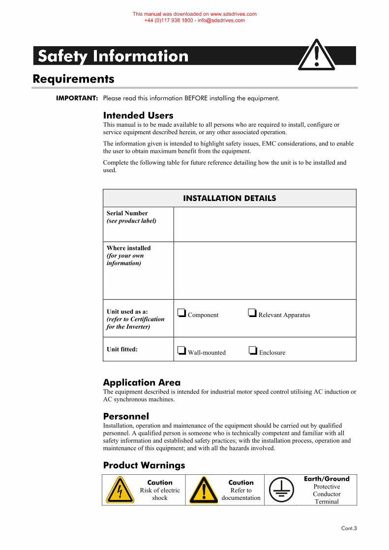
Requirements IMPORTANT: Please read this information BEFORE installing the equipment.
Intended Users This manual is to be made available to all persons who are required to install, configure or service equipment described herein, or any other associated operation.
The information given is intended to highlight safety issues, EMC considerations, and to enable the user to obtain maximum benefit from the equipment.
Complete the following table for future reference detailing how the unit is to be installed and used.
INSTALLATION DETAILS
Serial Number (see product label)
Where installed (for your own information)
Unit used as a: (refer to Certification for the Inverter)
Component Relevant Apparatus
Unit fitted: Wall-mounted Enclosure
Application Area The equipment described is intended for industrial motor speed control utilising AC induction or AC synchronous machines.
Personnel Installation, operation and maintenance of the equipment should be carried out by qualified personnel. A qualified person is someone who is technically competent and familiar with all safety information and established safety practices; with the installation process, operation and maintenance of this equipment; and with all the hazards involved.
Product Warnings
Caution Risk of electric
shock
Caution Refer to
documentation
Earth/Ground Protective Conductor Terminal
This manual was downloaded on www.sdsdrives.com +44 (0)117 938 1800 - [email protected]
Cont.4
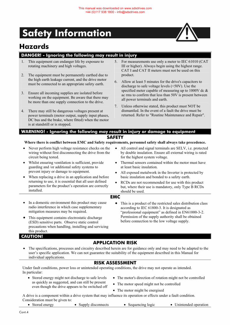
Hazards DANGER! - Ignoring the following may result in injury 1. This equipment can endanger life by exposure to
rotating machinery and high voltages.
2. The equipment must be permanently earthed due to the high earth leakage current, and the drive motor must be connected to an appropriate safety earth.
3. Ensure all incoming supplies are isolated before working on the equipment. Be aware that there may be more than one supply connection to the drive.
4. There may still be dangerous voltages present at power terminals (motor output, supply input phases, DC bus and the brake, where fitted) when the motor is at standstill or is stopped.
5. For measurements use only a meter to IEC 61010 (CAT III or higher). Always begin using the highest range. CAT I and CAT II meters must not be used on this product.
6. Allow at least 5 minutes for the drive's capacitors to discharge to safe voltage levels (<50V). Use the specified meter capable of measuring up to 1000V dc & ac rms to confirm that less than 50V is present between all power terminals and earth.
7. Unless otherwise stated, this product must NOT be dismantled. In the event of a fault the drive must be returned. Refer to "Routine Maintenance and Repair".
WARNING! - Ignoring the following may result in injury or damage to equipment SAFETY
Where there is conflict between EMC and Safety requirements, personnel safety shall always take precedence. • Never perform high voltage resistance checks on the
wiring without first disconnecting the drive from the circuit being tested.
• Whilst ensuring ventilation is sufficient, provide guarding and /or additional safety systems to prevent injury or damage to equipment.
• When replacing a drive in an application and before returning to use, it is essential that all user defined parameters for the product’s operation are correctly installed.
• All control and signal terminals are SELV, i.e. protected by double insulation. Ensure all external wiring is rated for the highest system voltage.
• Thermal sensors contained within the motor must have at least basic insulation.
• All exposed metalwork in the Inverter is protected by basic insulation and bonded to a safety earth.
• RCDs are not recommended for use with this product but, where their use is mandatory, only Type B RCDs should be used.
EMC • In a domestic environment this product may cause
radio interference in which case supplementary mitigation measures may be required.
• This equipment contains electrostatic discharge (ESD) sensitive parts. Observe static control precautions when handling, installing and servicing this product.
• This is a product of the restricted sales distribution class according to IEC 61800-3. It is designated as “professional equipment” as defined in EN61000-3-2. Permission of the supply authority shall be obtained before connection to the low voltage supply.
CAUTION! APPLICATION RISK
• The specifications, processes and circuitry described herein are for guidance only and may need to be adapted to the user’s specific application. We can not guarantee the suitability of the equipment described in this Manual for individual applications.
RISK ASSESSMENT Under fault conditions, power loss or unintended operating conditions, the drive may not operate as intended. In particular:
• Stored energy might not discharge to safe levels as quickly as suggested, and can still be present even though the drive appears to be switched off
• The motor's direction of rotation might not be controlled • The motor speed might not be controlled • The motor might be energised
A drive is a component within a drive system that may influence its operation or effects under a fault condition. Consideration must be given to:
• Stored energy • Supply disconnects • Sequencing logic • Unintended operation
This manual was downloaded on www.sdsdrives.com +44 (0)117 938 1800 - [email protected]
Contents
Contents Page
Cont.5
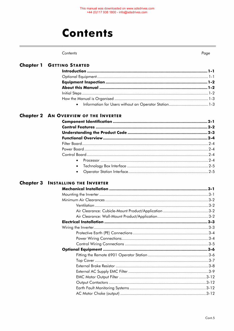
Chapter 1 GETTING STARTED Introduction ..................................................................................................1-1 Optional Equipment ................................................................................................1-1 Equipment Inspection ...................................................................................1-2 About this Manual ........................................................................................1-2 Initial Steps .............................................................................................................1-2 How the Manual is Organised .................................................................................1-3
• Information for Users without an Operator Station..................................1-3
Chapter 2 AN OVERVIEW OF THE INVERTER Component Identification .............................................................................2-1 Control Features ...........................................................................................2-2 Understanding the Product Code .................................................................2-3 Functional Overview .....................................................................................2-4 Filter Board.............................................................................................................2-4 Power Board ...........................................................................................................2-4 Control Board.........................................................................................................2-4
• Processor .............................................................................................2-4 • Technology Box Interface ......................................................................2-5 • Operator Station Interface.....................................................................2-5
Chapter 3 INSTALLING THE INVERTER
Mechanical Installation ................................................................................3-1 Mounting the Inverter ..............................................................................................3-1 Minimum Air Clearances .........................................................................................3-2
Ventilation ..................................................................................................3-2 Air Clearance: Cubicle-Mount Product/Application .......................................3-2 Air Clearance: Wall-Mount Product/Application............................................3-2
Electrical Installation ....................................................................................3-3 Wiring the Inverter...................................................................................................3-3
Protective Earth (PE) Connections .................................................................3-4 Power Wiring Connections...........................................................................3-4 Control Wiring Connections ........................................................................3-5
Optional Equipment .....................................................................................3-6 Fitting the Remote 6901 Operator Station ....................................................3-6 Top Cover ..................................................................................................3-7 External Brake Resistor ................................................................................3-8 External AC Supply EMC Filter .....................................................................3-9 EMC Motor Output Filter ...........................................................................3-12 Output Contactors ....................................................................................3-12 Earth Fault Monitoring Systems ..................................................................3-12 AC Motor Choke (output) ..........................................................................3-12
This manual was downloaded on www.sdsdrives.com +44 (0)117 938 1800 - [email protected]
Contents
Contents Page
Cont.6
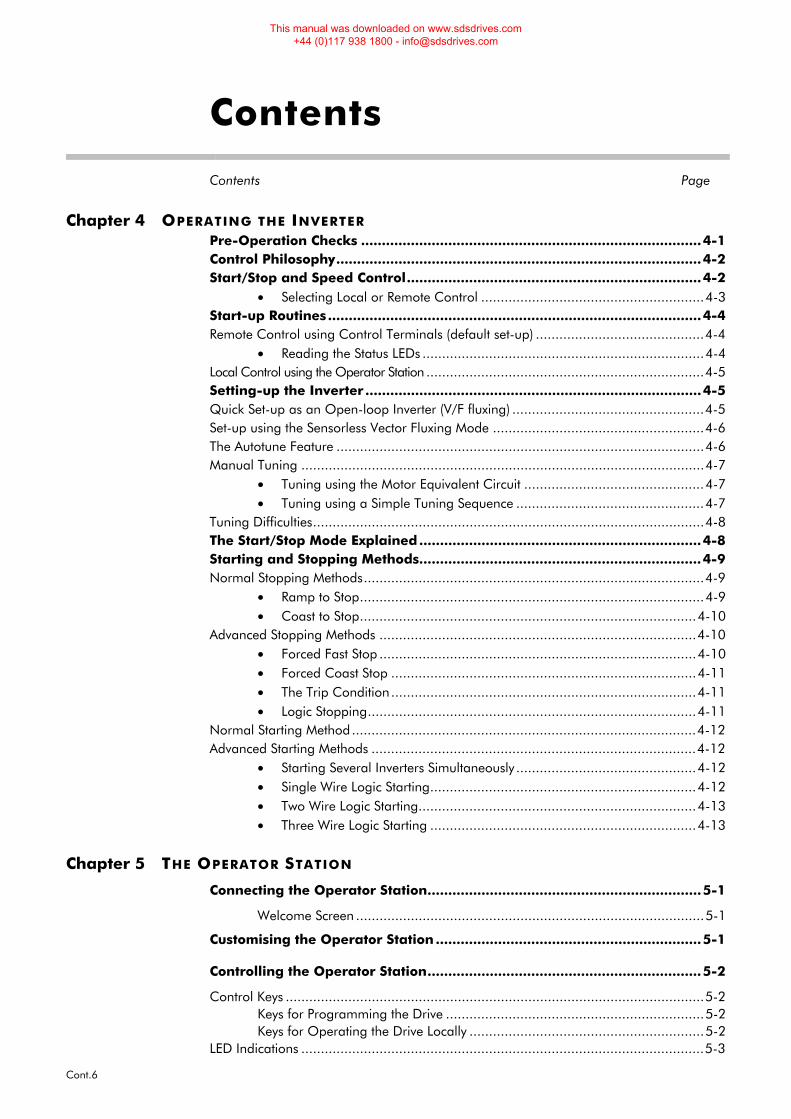
Chapter 4 OPERATING THE INVERTER Pre-Operation Checks ..................................................................................4-1 Control Philosophy........................................................................................4-2 Start/Stop and Speed Control.......................................................................4-2
• Selecting Local or Remote Control .........................................................4-3 Start-up Routines..........................................................................................4-4 Remote Control using Control Terminals (default set-up) ...........................................4-4
• Reading the Status LEDs ........................................................................4-4 Local Control using the Operator Station .......................................................................4-5 Setting-up the Inverter .................................................................................4-5 Quick Set-up as an Open-loop Inverter (V/F fluxing) .................................................4-5 Set-up using the Sensorless Vector Fluxing Mode ......................................................4-6 The Autotune Feature ..............................................................................................4-6 Manual Tuning .......................................................................................................4-7
• Tuning using the Motor Equivalent Circuit ..............................................4-7 • Tuning using a Simple Tuning Sequence ................................................4-7
Tuning Difficulties....................................................................................................4-8 The Start/Stop Mode Explained....................................................................4-8 Starting and Stopping Methods....................................................................4-9 Normal Stopping Methods.......................................................................................4-9
• Ramp to Stop........................................................................................4-9 • Coast to Stop......................................................................................4-10
Advanced Stopping Methods .................................................................................4-10 • Forced Fast Stop .................................................................................4-10 • Forced Coast Stop ..............................................................................4-11 • The Trip Condition..............................................................................4-11 • Logic Stopping....................................................................................4-11
Normal Starting Method........................................................................................4-12 Advanced Starting Methods ...................................................................................4-12
• Starting Several Inverters Simultaneously ..............................................4-12 • Single Wire Logic Starting....................................................................4-12 • Two Wire Logic Starting.......................................................................4-13 • Three Wire Logic Starting ....................................................................4-13
Chapter 5 THE OPERATOR STATION
Connecting the Operator Station..................................................................5-1
Welcome Screen .........................................................................................5-1
Customising the Operator Station ................................................................5-1
Controlling the Operator Station..................................................................5-2
Control Keys ...........................................................................................................5-2 Keys for Programming the Drive ..................................................................5-2 Keys for Operating the Drive Locally ............................................................5-2
LED Indications .......................................................................................................5-3
This manual was downloaded on www.sdsdrives.com +44 (0)117 938 1800 - [email protected]
Contents
Contents Page
Cont.7
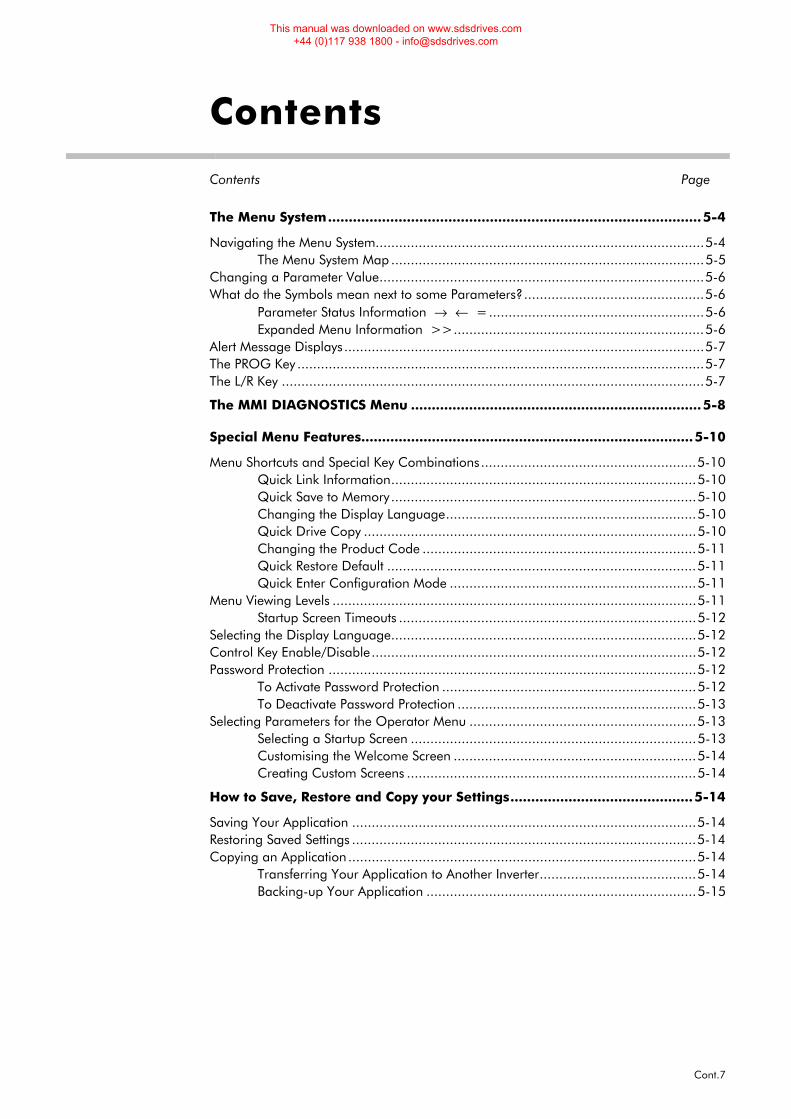
The Menu System..........................................................................................5-4
Navigating the Menu System....................................................................................5-4 The Menu System Map ................................................................................5-5
Changing a Parameter Value...................................................................................5-6 What do the Symbols mean next to some Parameters?..............................................5-6
Parameter Status Information → ← =.......................................................5-6 Expanded Menu Information >>................................................................5-6
Alert Message Displays............................................................................................5-7 The PROG Key ........................................................................................................5-7 The L/R Key ............................................................................................................5-7
The MMI DIAGNOSTICS Menu ......................................................................5-8
Special Menu Features................................................................................5-10
Menu Shortcuts and Special Key Combinations.......................................................5-10 Quick Link Information..............................................................................5-10 Quick Save to Memory..............................................................................5-10 Changing the Display Language................................................................5-10 Quick Drive Copy .....................................................................................5-10 Changing the Product Code ......................................................................5-11 Quick Restore Default ...............................................................................5-11 Quick Enter Configuration Mode ...............................................................5-11
Menu Viewing Levels .............................................................................................5-11 Startup Screen Timeouts ............................................................................5-12
Selecting the Display Language..............................................................................5-12 Control Key Enable/Disable...................................................................................5-12 Password Protection ..............................................................................................5-12
To Activate Password Protection .................................................................5-12 To Deactivate Password Protection .............................................................5-13
Selecting Parameters for the Operator Menu ..........................................................5-13 Selecting a Startup Screen .........................................................................5-13 Customising the Welcome Screen ..............................................................5-14 Creating Custom Screens ..........................................................................5-14
How to Save, Restore and Copy your Settings............................................5-14
Saving Your Application ........................................................................................5-14 Restoring Saved Settings ........................................................................................5-14 Copying an Application .........................................................................................5-14
Transferring Your Application to Another Inverter........................................5-14 Backing-up Your Application .....................................................................5-15
This manual was downloaded on www.sdsdrives.com +44 (0)117 938 1800 - [email protected]
Contents
Contents Page
Cont.8
Chapter 6 PROGRAMMING YOUR APPLICATION Introducing the Macro ..................................................................................6-1 Programming with Block Diagrams .............................................................6-1 Modifying a Block Diagram .....................................................................................6-1
• Configuration and Parameterisation Modes ...........................................6-1 • Making and Breaking Links in Configuration Mode ................................6-1 • Programming Rules...............................................................................6-2
Execution Rules .............................................................................................6-2 • Saving Your Modifications .....................................................................6-3
Understanding the Function Block Description ..........................................................6-3 • MMI Menu Maps ..................................................................................6-3
Hexadecimal Representation of Trips........................................................................6-4 Function Block Descriptions ..........................................................................6-5
• ANALOG DIGIN...................................................................................6-6 • ANALOG INPUT...................................................................................6-8 • ANALOG OUTPUT .............................................................................6-10 • AUTO RESTART..................................................................................6-12 • AUTOTUNE........................................................................................6-14 • BRAKE CONTROL...............................................................................6-15 • COMMS CONTROL............................................................................6-16 • CURRENT FEEDBACK..........................................................................6-17 • CURRENT LIMIT ..................................................................................6-19 • CUSTOM SCREEN ..............................................................................6-20 • DEMULTIPLEXER .................................................................................6-22 • DIGITAL INPUT...................................................................................6-23 • DIGITAL OUTPUT ...............................................................................6-24 • DYNAMIC BRAKING...........................................................................6-25 • ENCODER..........................................................................................6-26 • FLUXING............................................................................................6-27 • FLYCATCHING...................................................................................6-29 • I/O TRIPS ...........................................................................................6-31 • I*t TRIP ...............................................................................................6-32 • INJ BRAKING......................................................................................6-33 • JOG ..................................................................................................6-34 • LOCAL CONTROL..............................................................................6-35 • LOGIC FUNCTION ............................................................................6-36 • MINIMUM SPEED................................................................................6-40 • MULTIPLEXER......................................................................................6-41 • OPERATOR MENU..............................................................................6-42 • OP STATION ......................................................................................6-43 • PASSWORD........................................................................................6-45 • PATTERN GEN....................................................................................6-46 • PID ....................................................................................................6-47 • PRESET ...............................................................................................6-49
This manual was downloaded on www.sdsdrives.com +44 (0)117 938 1800 - [email protected]
Contents
Contents Page
Cont.9
• RAISE/LOWER.....................................................................................6-51 • REFERENCE........................................................................................6-52 • SEQUENCING LOGIC........................................................................6-54 • SETPOINT SCALE................................................................................6-56 • SKIP FREQUENCIES ............................................................................6-57 • SLEW RATE LIMIT ................................................................................6-59 • SLIP COMP.........................................................................................6-60 • STABILISATION...................................................................................6-61 • STALL TRIP..........................................................................................6-62 • STOP .................................................................................................6-63 • SYSTEM PORT (P3)..............................................................................6-64 • SYSTEM RAMP ....................................................................................6-65 • TEC OPTION......................................................................................6-67 • TRIPS HISTORY ...................................................................................6-68 • TRIPS STATUS .....................................................................................6-69 • UNDERLAP COMP..............................................................................6-71 • VALUE FUNCTIONS ...........................................................................6-72 • VECTOR FLUXING..............................................................................6-79 • VOLTAGE CONTROL..........................................................................6-80 • ZERO SPEED.......................................................................................6-81
Motor-Specific Parameters .........................................................................6-82
Chapter 7 TRIPS AND FAULT FINDING Trips ..............................................................................................................7-1 What Happens when a Trip Occurs..........................................................................7-1
• Inverter Indications................................................................................7-1 • Operator Station Indications (when connected).......................................7-1
Resetting a Trip Condition........................................................................................7-1 Using the Operator Station to Manage Trips.............................................................7-2
• Trip Messages ......................................................................................7-2 • Automatic Trip Reset .............................................................................7-3 • Setting Trip Conditions ..........................................................................7-3 • Viewing Trip Conditions ........................................................................7-3
Checksum Fail ........................................................................................................7-3 • Inverter Indications................................................................................7-3 • Operator Station Indications (when connected).......................................7-4
Fault Finding.................................................................................................7-4
Chapter 8 ROUTINE MAINTENANCE AND REPAIR Routine Maintenance....................................................................................8-1 Repair ...........................................................................................................8-1 Saving Your Application Data ..................................................................................8-1 Returning the Unit to Parker SSD Drives....................................................................8-1 Disposal .................................................................................................................8-1
This manual was downloaded on www.sdsdrives.com +44 (0)117 938 1800 - [email protected]
Contents
Contents Page
Cont.10
Chapter 9 SEQUENCING LOGIC Principle State Machine ................................................................................9-1 Main Sequencing States...........................................................................................9-1 State Outputs of the SEQUENCING LOGIC Function Block .......................................9-1 Transition of States ..................................................................................................9-2 State Diagram.........................................................................................................9-3 Communications Command ..........................................................................9-4
• Example Commands.............................................................................9-5 Communications Status ...........................................................................................9-6
Chapter 10 PARAMETER SPECIFICATION TABLE Specification Table: Tag Number Order.....................................................10-2 Product-Related Default Values ...............................................................10-18
• Language Dependant Defaults ..........................................................10-18 • AC Supply Voltage and Power Rating Dependant Defaults ..................10-18
Chapter 11 TECHNICAL SPECIFICATIONS
Environmental Details............................................................................................11-1 EMC Compliance..................................................................................................11-1 External AC Supply (RFI) Filters...............................................................................11-1 Cabling Requirements for EMC Compliance ...........................................................11-2 Fuse Rating and Recommended Wire Sizes .............................................................11-2 Terminal Block Wire Sizes ......................................................................................11-3 Earthing/Safety Details ..........................................................................................11-3 Power Details ........................................................................................................11-3 Control Terminals .................................................................................................11-4 Analog Inputs/Outputs ..........................................................................................11-5 Digital Inputs ........................................................................................................11-5 Digital Outputs .....................................................................................................11-5 Power Loss Estimates .............................................................................................11-5 Switching Frequencies ...........................................................................................11-5 Supply Harmonic Analysis......................................................................................11-6
Chapter 12 CERTIFICATION FOR THE INVERTER Requirements for EMC Compliance.............................................................12-1 Minimising Radiated Emissions ..............................................................................12-1 Earthing Requirements...........................................................................................12-1
Protective Earth (PE) Connections ...............................................................12-1 EMC Earth Connections ............................................................................12-1
Cabling Requirements ...........................................................................................12-2 Planning Cable Runs.................................................................................12-2 Increasing Motor Cable Length..................................................................12-2
EMC Installation Options .......................................................................................12-3 Screening & Earthing (wall mounted, Class A) ............................................12-3 Screening & Earthing (cubicle mounted, Class B) ........................................12-3
This manual was downloaded on www.sdsdrives.com +44 (0)117 938 1800 - [email protected]
Contents
Contents Page
Cont.11
Star Point Earthing ....................................................................................12-4 Sensitive Equipment ..................................................................................12-5
Requirements for UL Compliance ...............................................................12-6 Solid-State Motor Overload Protection........................................................12-6 Short Circuit Rating ...................................................................................12-6 Solid-State Short-Circuit Protection.............................................................12-6 Recommended Branch Circuit Protection ....................................................12-6 Motor Base Frequency...............................................................................12-6 Field Wiring Temperature Rating................................................................12-6 Field Wiring Terminal Markings .................................................................12-6 Power Wiring Terminals ............................................................................12-6 Terminal Tightening Torque.......................................................................12-6 Field Grounding Terminals ........................................................................12-6 Operating Ambient Temperature ...............................................................12-6 Direct Wall-Mountable Models...................................................................12-6
European Directives and the CE Mark........................................................12-7 CE Marking for Low Voltage Directive ....................................................................12-7 CE Marking for EMC - Who is Responsible?............................................................12-7
The Legal Requirements of CE Marking for EMC.........................................12-8 Applying for CE Marking for EMC..............................................................12-8
Which Standards Apply?........................................................................................12-9 Basic and Generic Standards.....................................................................12-9
Certificates..........................................................................................................12-12
Chapter 13 APPLICATION NOTES
Synchronous Motor Control ........................................................................13-1 Brake Motors ..............................................................................................13-1 Using Multiple Motors on a Single Inverter ...............................................13-2 Dynamic Braking ........................................................................................13-2 Brake Resistor Selection .............................................................................13-3
Chapter 14 SERIAL COMMUNICATIONS Connection to the P3 Port ...........................................................................14-1
This manual was downloaded on www.sdsdrives.com +44 (0)117 938 1800 - [email protected]
Contents
Contents Page
Cont.12
Chapter 15 APPLICATION MACROS The Default Application ..............................................................................15-1 How to Load a Macro..................................................................................15-1 Macro Descriptions .....................................................................................15-1 Macro 0 ...............................................................................................................15-1 Macro 1: Basic Speed Control (default) ..................................................................15-3 Macro 2: Run Forward/Run Reverse .......................................................................15-5 Macro 3: Raise/Lower Trim....................................................................................15-7 Macro 4: Process PID ............................................................................................15-9 Macro 5: Preset Speeds .......................................................................................15-11 Macro 6: Closed-Loop Speed Feedback ...............................................................15-13 Macro Control Blocks ..........................................................................................15-15 Macro User Blocks ..............................................................................................15-16
This manual was downloaded on www.sdsdrives.com +44 (0)117 938 1800 - [email protected]
Getting Started 1-1
605 Series Frequency Inverter
1GETTING STARTED Introduction
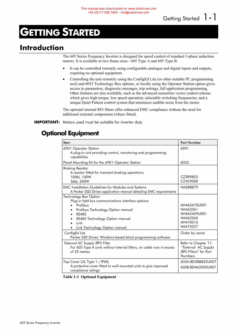
The 605 Series Frequency Inverter is designed for speed control of standard 3-phase induction motors. It is available in two frame sizes - 605 Type A and 605 Type B.
• It can be controlled remotely using configurable analogue and digital inputs and outputs, requiring no optional equipment.
• Controlling the unit remotely using the ConfigEd Lite (or other suitable PC programming tool) and 6053 Technology Box options, or locally using the Operator Station option gives access to parameters, diagnostic messages, trip settings, full application programming. Other features are also available, such as the advanced sensorless vector control scheme which gives high torque, low speed operation; selectable switching frequencies; and a unique Quiet Pattern control system that minimises audible noise from the motor.
The optional internal RFI filters offer enhanced EMC compliance without the need for additional external components (where fitted).
IMPORTANT: Motors used must be suitable for inverter duty.
Optional Equipment Item Part Number
6901 Operator Station A plug-in unit providing control, monitoring and programming capabilities
6901
Panel Mounting Kit for the 6901 Operator Station 6052
Braking Resistor A resistor fitted for transient braking operations 100Ω, 100W 56Ω, 200W
CZ389853 CZ463068
EMC Installation Guidelines for Modules and Systems A Parker SSD Drives application manual detailing EMC requirements
HA388879
Technology Box Option Plug-in field bus communications interface options: • Profibus • Profibus Technology Option manual • RS485 • RS485 Technology Option manual • Link • Link Technology Option manual
AH463470U001 HA463561 AH463469U001 HA463560 AH470016 HA470237
ConfigEd Lite Parker SSD Drives’ Windows-based block programming software
Order by name
External AC Supply (RFI) Filter For 605 Type A units without internal filters, on cable runs in excess of 25 metres
Refer to Chapter 11: “External AC Supply (RFI) Filters” for Part Numbers
Top Cover (UL Type 1 / IP4X) A protective cover fitted to wall-mounted units to give improved compliance ratings
605A:BD388832U007
605B:BD463503U007
Table 1-1 Optional Equipment
This manual was downloaded on www.sdsdrives.com +44 (0)117 938 1800 - [email protected]
1-2 Getting Started
605 Series Frequency Inverter
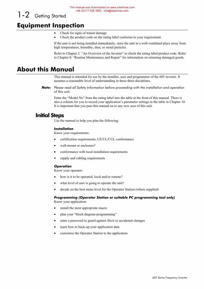
Equipment Inspection • Check for signs of transit damage • Check the product code on the rating label conforms to your requirement.
If the unit is not being installed immediately, store the unit in a well-ventilated place away from high temperatures, humidity, dust, or metal particles.
Refer to Chapter 2: “An Overview of the Inverter” to check the rating label/product code. Refer to Chapter 8: “Routine Maintenance and Repair” for information on returning damaged goods.
About this Manual This manual is intended for use by the installer, user and programmer of the 605 inverter. It assumes a reasonable level of understanding in these three disciplines.
Note: Please read all Safety Information before proceeding with the installation and operation of this unit.
Enter the “Model No” from the rating label into the table at the front of this manual. There is also a column for you to record your application’s parameter settings in the table in Chapter 10. It is important that you pass this manual on to any new user of this unit.
Initial Steps Use the manual to help you plan the following:
Installation Know your requirements:
• certification requirements, CE/UL/CUL conformance
• wall-mount or enclosure?
• conformance with local installation requirements
• supply and cabling requirements
Operation Know your operator:
• how is it to be operated, local and/or remote?
• what level of user is going to operate the unit?
• decide on the best menu level for the Operator Station (where supplied)
Programming (Operator Station or suitable PC programming tool only) Know your application:
• install the most appropriate macro
• plan your “block diagram programming”
• enter a password to guard against illicit or accidental changes
• learn how to back-up your application data
• customise the Operator Station to the application
This manual was downloaded on www.sdsdrives.com +44 (0)117 938 1800 - [email protected]
Getting Started 1-3
605 Series Frequency Inverter
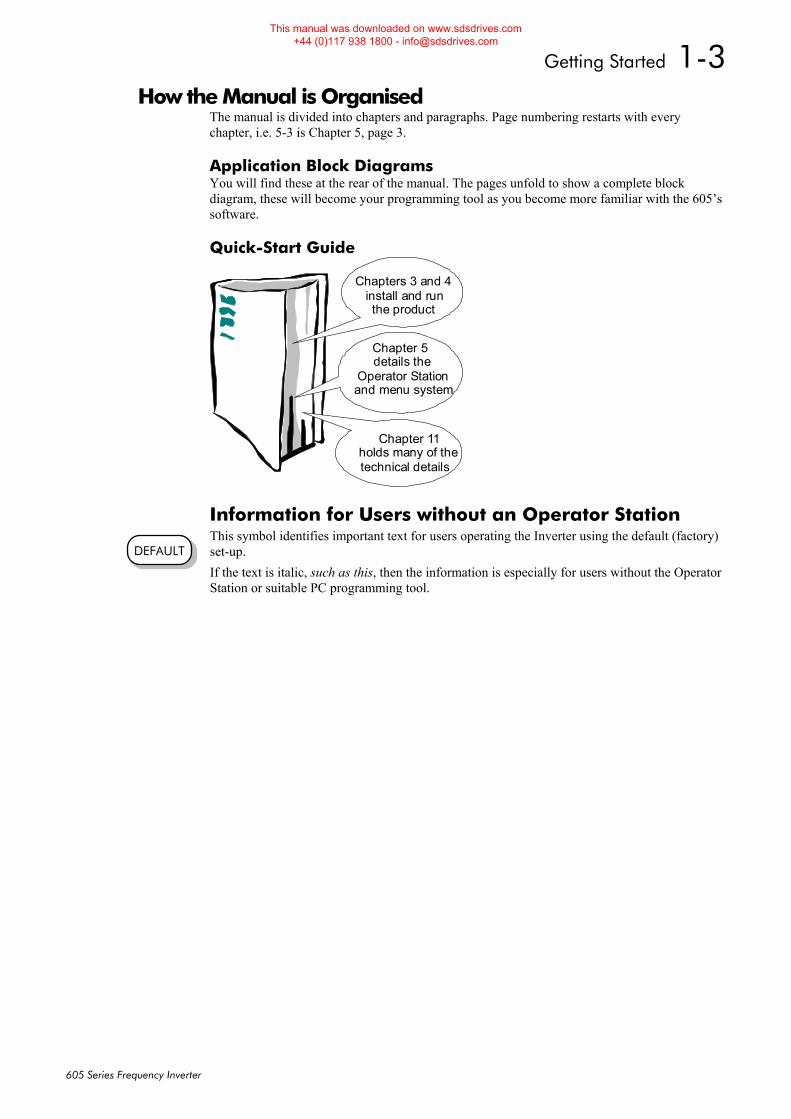
How the Manual is Organised The manual is divided into chapters and paragraphs. Page numbering restarts with every chapter, i.e. 5-3 is Chapter 5, page 3.
Application Block Diagrams You will find these at the rear of the manual. The pages unfold to show a complete block diagram, these will become your programming tool as you become more familiar with the 605’s software.
Quick-Start Guide
Chapters 3 and 4 install and run the product
details the Operator Station and menu system
Chapter 5
Chapter 11
technical details
holds many of the
Information for Users without an Operator Station This symbol identifies important text for users operating the Inverter using the default (factory) set-up. If the text is italic, such as this, then the information is especially for users without the Operator Station or suitable PC programming tool.
DEFAULT
This manual was downloaded on www.sdsdrives.com +44 (0)117 938 1800 - [email protected]

1-4 Getting Started
605 Series Frequency Inverter
This manual was downloaded on www.sdsdrives.com +44 (0)117 938 1800 - [email protected]
An Overview of the Inverter 2-1
605 Series Frequency Inverter
2AN OVERVIEW OF THE INVERTER Component Identification
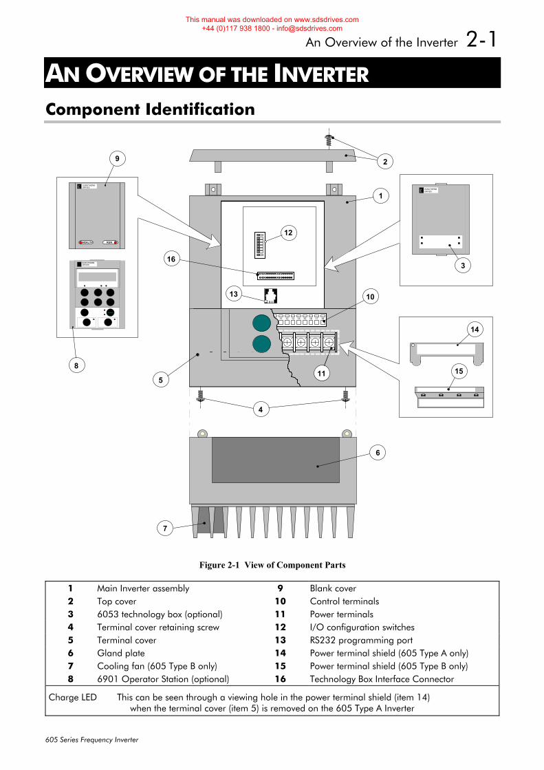
Figure 2-1 View of Component Parts
1 Main Inverter assembly 9 Blank cover 2 Top cover 10 Control terminals 3 6053 technology box (optional) 11 Power terminals 4 Terminal cover retaining screw 12 I/O configuration switches 5 Terminal cover 13 RS232 programming port 6 Gland plate 14 Power terminal shield (605 Type A only) 7 Cooling fan (605 Type B only) 15 Power terminal shield (605 Type B only) 8 6901 Operator Station (optional) 16 Technology Box Interface Connector
Charge LED This can be seen through a viewing hole in the power terminal shield (item 14) when the terminal cover (item 5) is removed on the 605 Type A Inverter
EUROTHERMDRIVES
6
1
29
8
10
12
13
14
3
HEALTH RUN
E PROG
LR
11
M
5
4
1 2 3 4 5 6 7 8 9 10 11 12 13 14 15 16 17 18
11
7
L1 L2/NL3 DC+DBRDC-M1/UM2/VM3/WCHARGE
15
16
EUROTHERMDRIVES
EUROTHERMDRIVES
This manual was downloaded on www.sdsdrives.com +44 (0)117 938 1800 - [email protected]
2-2 An Overview of the Inverter
605 Series Frequency Inverter
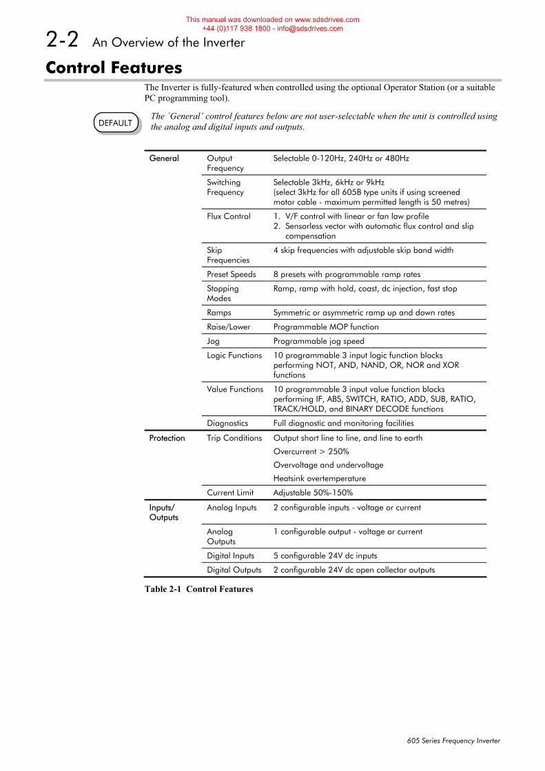
Control Features The Inverter is fully-featured when controlled using the optional Operator Station (or a suitable PC programming tool).
The `General’ control features below are not user-selectable when the unit is controlled using the analog and digital inputs and outputs.
General Output Frequency
Selectable 0-120Hz, 240Hz or 480Hz
Switching Frequency
Selectable 3kHz, 6kHz or 9kHz (select 3kHz for all 605B type units if using screened motor cable - maximum permitted length is 50 metres)
Flux Control 1. V/F control with linear or fan law profile 2. Sensorless vector with automatic flux control and slip compensation
Skip Frequencies
4 skip frequencies with adjustable skip band width
Preset Speeds 8 presets with programmable ramp rates
Stopping Modes
Ramp, ramp with hold, coast, dc injection, fast stop
Ramps Symmetric or asymmetric ramp up and down rates
Raise/Lower Programmable MOP function
Jog Programmable jog speed
Logic Functions 10 programmable 3 input logic function blocks performing NOT, AND, NAND, OR, NOR and XOR functions
Value Functions 10 programmable 3 input value function blocks performing IF, ABS, SWITCH, RATIO, ADD, SUB, RATIO, TRACK/HOLD, and BINARY DECODE functions
Diagnostics Full diagnostic and monitoring facilities
Protection Trip Conditions Output short line to line, and line to earth
Overcurrent > 250%
Overvoltage and undervoltage
Heatsink overtemperature
Current Limit Adjustable 50%-150%
Inputs/ Outputs
Analog Inputs 2 configurable inputs - voltage or current
Analog Outputs
1 configurable output - voltage or current
Digital Inputs 5 configurable 24V dc inputs
Digital Outputs 2 configurable 24V dc open collector outputs
Table 2-1 Control Features
DEFAULT
This manual was downloaded on www.sdsdrives.com +44 (0)117 938 1800 - [email protected]
An Overview of the Inverter 2-3
605 Series Frequency Inverter
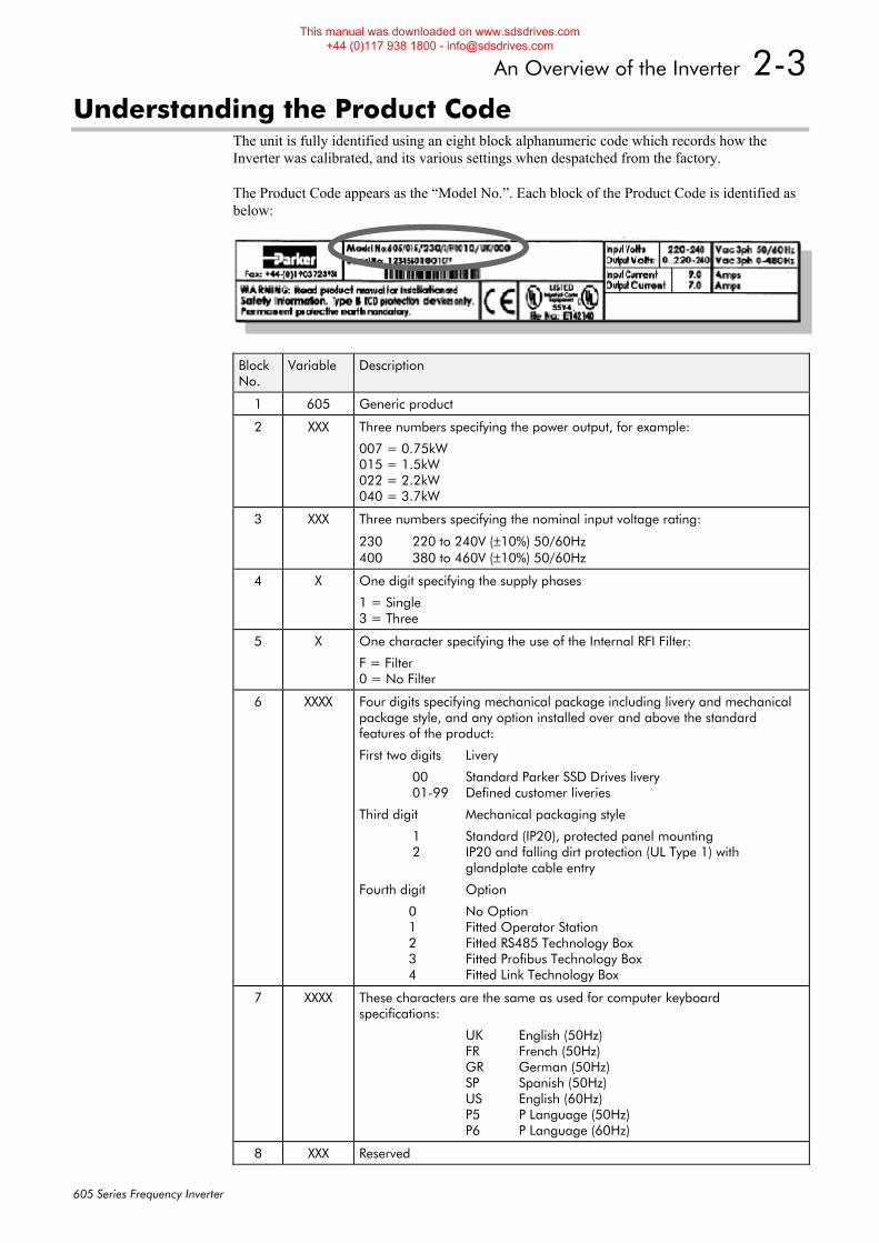
Understanding the Product Code The unit is fully identified using an eight block alphanumeric code which records how the Inverter was calibrated, and its various settings when despatched from the factory.
The Product Code appears as the “Model No.”. Each block of the Product Code is identified as below:
Block No.
Variable Description
1 605 Generic product
2 XXX Three numbers specifying the power output, for example:
007 = 0.75kW 015 = 1.5kW 022 = 2.2kW 040 = 3.7kW
3 XXX Three numbers specifying the nominal input voltage rating:
230 220 to 240V (±10%) 50/60Hz 400 380 to 460V (±10%) 50/60Hz
4 X One digit specifying the supply phases
1 = Single 3 = Three
5 X One character specifying the use of the Internal RFI Filter:
F = Filter 0 = No Filter
6 XXXX Four digits specifying mechanical package including livery and mechanical package style, and any option installed over and above the standard features of the product:
First two digits Livery
00 Standard Parker SSD Drives livery 01-99 Defined customer liveries
Third digit Mechanical packaging style
1 Standard (IP20), protected panel mounting 2 IP20 and falling dirt protection (UL Type 1) with glandplate cable entry
Fourth digit Option
0 No Option 1 Fitted Operator Station 2 Fitted RS485 Technology Box 3 Fitted Profibus Technology Box 4 Fitted Link Technology Box
7 XXXX These characters are the same as used for computer keyboard specifications:
UK English (50Hz) FR French (50Hz) GR German (50Hz) SP Spanish (50Hz) US English (60Hz) P5 P Language (50Hz) P6 P Language (60Hz)
8 XXX Reserved
This manual was downloaded on www.sdsdrives.com +44 (0)117 938 1800 - [email protected]
2-4 An Overview of the Inverter
605 Series Frequency Inverter
Functional Overview
14 13 12 11 10 9 8 7 6 5 4 3 2 1
PROCESSOR POWER
FILTER
CONTROL
M1 M2 M3
PE
DC+
DC-
DBR
L1 L2/N L3
CONTROL TERMINALS
6901
18 17 16 15
PROGRAMMING PORT
U V W
RS232 OPERATOR INTERFACE
STATION
INTERFACE TECHNOLOGY BOX
605A: Diode Bridge on Filter Board 605B: Diode Bridge on Power Board Diode Bridge
TECHNOLOGY BOX INTERFACE CONNECTOR
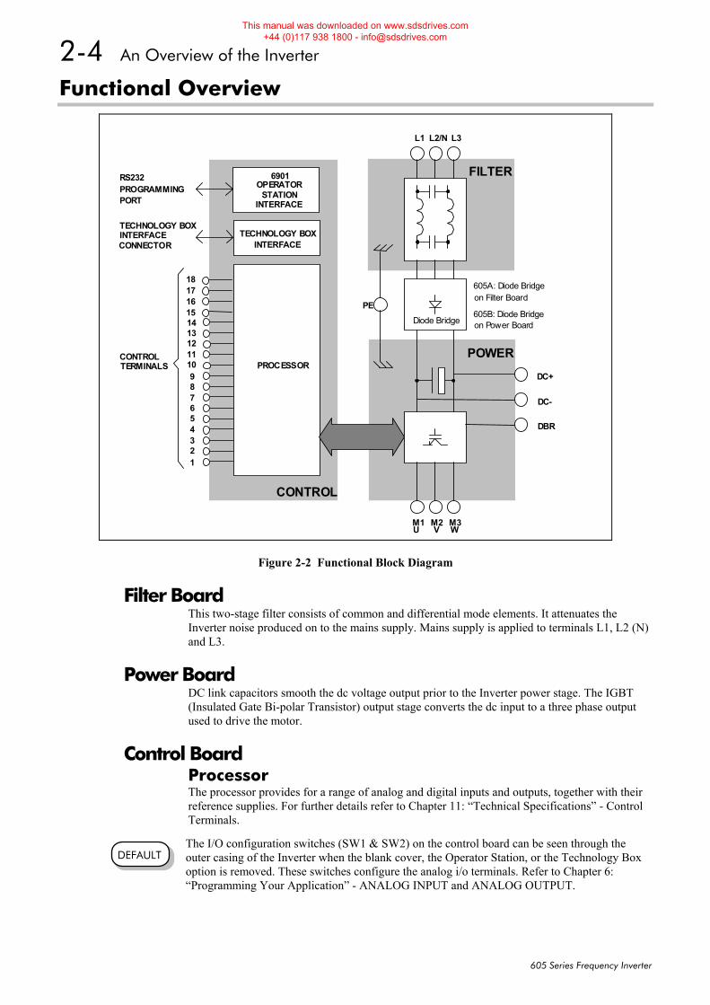
Figure 2-2 Functional Block Diagram
Filter Board This two-stage filter consists of common and differential mode elements. It attenuates the Inverter noise produced on to the mains supply. Mains supply is applied to terminals L1, L2 (N) and L3.
Power Board DC link capacitors smooth the dc voltage output prior to the Inverter power stage. The IGBT (Insulated Gate Bi-polar Transistor) output stage converts the dc input to a three phase output used to drive the motor.
Control Board Processor The processor provides for a range of analog and digital inputs and outputs, together with their reference supplies. For further details refer to Chapter 11: “Technical Specifications” - Control Terminals.
The I/O configuration switches (SW1 & SW2) on the control board can be seen through the outer casing of the Inverter when the blank cover, the Operator Station, or the Technology Box option is removed. These switches configure the analog i/o terminals. Refer to Chapter 6: “Programming Your Application” - ANALOG INPUT and ANALOG OUTPUT.
DEFAULT
This manual was downloaded on www.sdsdrives.com +44 (0)117 938 1800 - [email protected]

An Overview of the Inverter 2-5
605 Series Frequency Inverter
Technology Box Interface This is a multi-way connector and processor bus interface with control signals allowing various 6053 technology box options to be fitted to the Inverter.
Operator Station Interface This is a non-isolated RS232 serial link for communication with the Operator Station. Alternatively, a PC running Parker SSD Drives’ “ConfigEd Lite” Windows-based configuration software (or some other suitable PC programming tool) can be used to graphically program and configure the Inverter.
This manual was downloaded on www.sdsdrives.com +44 (0)117 938 1800 - [email protected]

2-6 An Overview of the Inverter
605 Series Frequency Inverter
This manual was downloaded on www.sdsdrives.com +44 (0)117 938 1800 - [email protected]
Installing the Inverter 3-1
605 Series Frequency Inverter
3INSTALLING THE INVERTER IMPORTANT: Read Chapter 12: “Certification for the Inverter” before installing this unit.
Mechanical Installation Mounting the Inverter
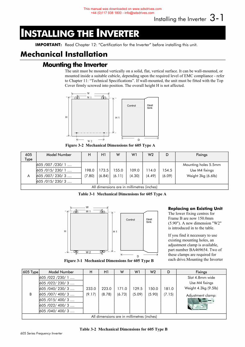
The unit must be mounted vertically on a solid, flat, vertical surface. It can be wall-mounted, or mounted inside a suitable cubicle, depending upon the required level of EMC compliance - refer to Chapter 11: “Technical Specifications”. If wall-mounted, the unit must be fitted with the Top Cover firmly screwed into position. The overall height H is not affected.
605 Type
Model Number H H1 W W1 W2 D Fixings
605 /007 /230/ 1 .... Mounting holes 5.5mm
605 /015/ 230/ 1 .... 198.0 173.5 155.0 109.0 114.0 154.5 Use M4 fixings
A 605 /007/ 230/ 3 .... (7.80) (6.84) (6.11) (4.30) (4.49) (6.09) Weight 3kg (6.6lb)
605 /015/ 230/ 3 ....
All dimensions are in millimetres (inches)
Table 3-1 Mechanical Dimensions for 605 Type A
WW 1
D
H H 1
W 2
HeatSink
Control
Figure 3-1 Mechanical Dimensions for 605 Type B
WW 1
W 2 D
H H 1
HeatSink
Control
Figure 3-2 Mechanical Dimensions for 605 Type A
605 Type Model Number H H1 W W1 W2 D Fixings
605 /022 /230/ 1 ....
605 /022/ 230/ 3 ....
605 /040/ 230/ 3 .... 233.0 223.0 171.0 129.5 150.0 181.0
B 605 /007/ 400/ 3 .... (9.17) (8.78) (6.73) (5.09) (5.90) (7.15)
605 /015/ 400/ 3 ....
605 /022/ 400/ 3 ....
605 /040/ 400/ 3 ....
Slot 4.8mm wide Use M4 fixings
Weight 4.3kg (9.5lb)
Adjustment clamp:
All dimensions are in millimetres (inches)
Table 3-2 Mechanical Dimensions for 605 Type B
Replacing an Existing Unit The lower fixing centres for Frame B are now 150.0mm (5.90"). A new dimension "W2" is introduced in to the table.
If you find it necessary to use existing mounting holes, an adjustment clamp is available, part number BA469654. Two of these clamps are required for each drive.Mounting the Inverter
This manual was downloaded on www.sdsdrives.com +44 (0)117 938 1800 - [email protected]
3-2 Installing the Inverter
605 Series Frequency Inverter
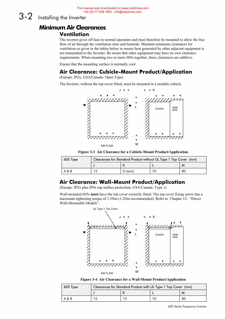
Minimum Air Clearances Ventilation The inverter gives off heat in normal operation and must therefore be mounted to allow the free flow of air through the ventilation slots and heatsink. Maintain minimum clearances for ventilation as given in the tables below to ensure heat generated by other adjacent equipment is not transmitted to the Inverter. Be aware that other equipment may have its own clearance requirements. When mounting two or more 605s together, these clearances are additive.
Ensure that the mounting surface is normally cool.
Air Clearance: Cubicle-Mount Product/Application (Europe: IP2x, USA/Canada: Open Type)
The Inverter, without the top cover fitted, must be mounted in a suitable cubicle.
HeatSink
J K
L
MAIR FLOW
Control
Figure 3-3 Air Clearance for a Cubicle-Mount Product/Application
605 Type Clearances for Standard Product without UL Type 1 Top Cover (mm)
J K L M
A & B 15 0 (zero) 70 80
Air Clearance: Wall-Mount Product/Application (Europe: IP2x plus IP4x top surface protection, USA/Canada: Type 1)
Wall-mounted 605s must have the top cover correctly fitted. The top cover fixing screw has a maximum tightening torque of 1.5Nm (1.2Nm recommended). Refer to Chapter 12: “Direct Wall-Mountable Models”.
HeatSink
J K
L
MAIR FLOW
UL Type 1 Top Cover
Control
Figure 3-4 Air Clearance for a Wall-Mount Product/Application
605 Type Clearances for Standard Product with UL Type 1 Top Cover (mm)
J K L M
A & B 15 15 70 80
This manual was downloaded on www.sdsdrives.com +44 (0)117 938 1800 - [email protected]
Installing the Inverter 3-3
605 Series Frequency Inverter
Electrical Installation IMPORTANT: Please read the Safety Information on page Cont. 3 & 4 before proceeding.
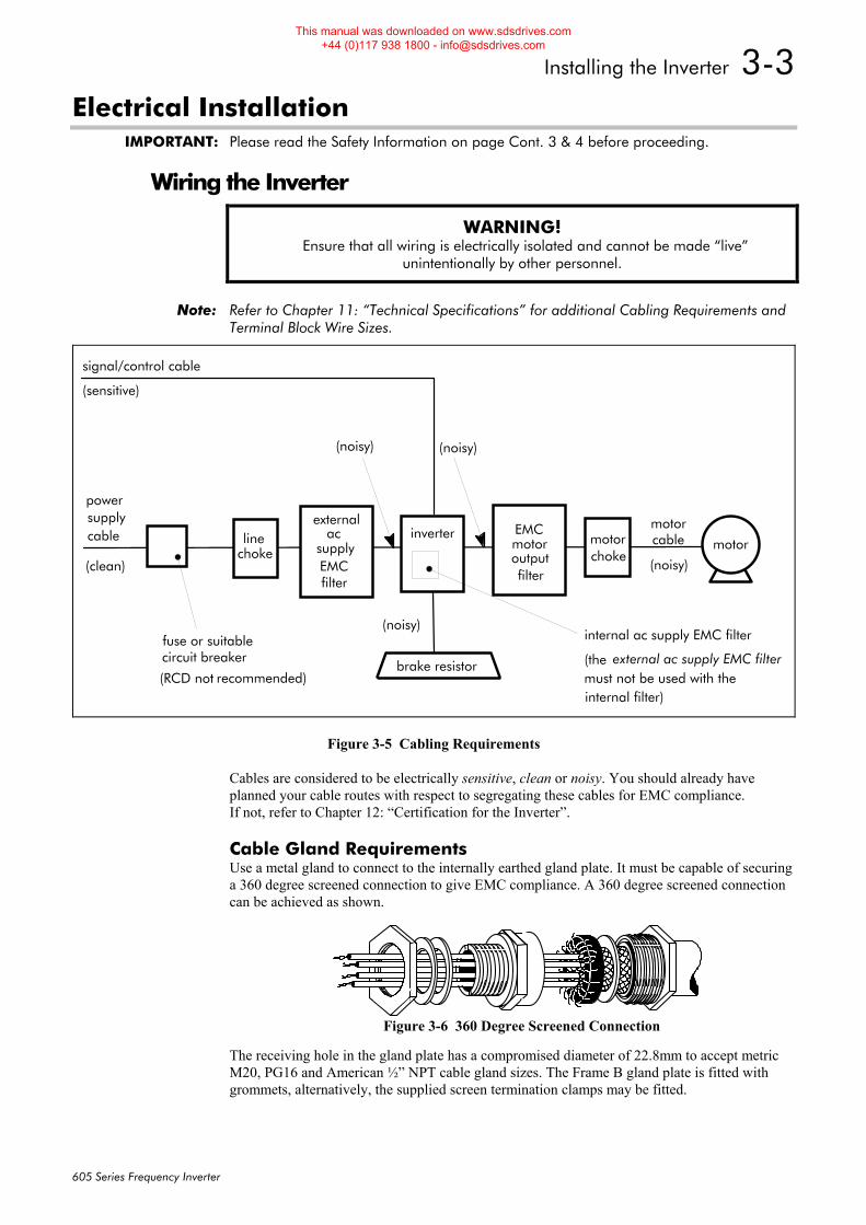
Wiring the Inverter
WARNING! Ensure that all wiring is electrically isolated and cannot be made “live”
unintentionally by other personnel.
Note: Refer to Chapter 11: “Technical Specifications” for additional Cabling Requirements and Terminal Block Wire Sizes.
inverter
filter
motor
brake resistor
(noisy)
(noisy)
signal/control cable
(sensitive)
powersupply
(clean)
cable ac
fuse or suitablecircuit breaker
(RCD not recommended)
linechoke
(noisy)
motorcable
supplyEMC
motorchoke
external ac supply EMC filter
internal ac supply EMC filter
must not be used with theinternal filter)
(the
(noisy)
filter
motoroutput
externalEMC
Figure 3-5 Cabling Requirements
Cables are considered to be electrically sensitive, clean or noisy. You should already have planned your cable routes with respect to segregating these cables for EMC compliance. If not, refer to Chapter 12: “Certification for the Inverter”.
Cable Gland Requirements Use a metal gland to connect to the internally earthed gland plate. It must be capable of securing a 360 degree screened connection to give EMC compliance. A 360 degree screened connection can be achieved as shown.
The receiving hole in the gland plate has a compromised diameter of 22.8mm to accept metric M20, PG16 and American ½” NPT cable gland sizes. The Frame B gland plate is fitted with grommets, alternatively, the supplied screen termination clamps may be fitted.
Figure 3-6 360 Degree Screened Connection
This manual was downloaded on www.sdsdrives.com +44 (0)117 938 1800 - [email protected]
3-4 Installing the Inverter
605 Series Frequency Inverter
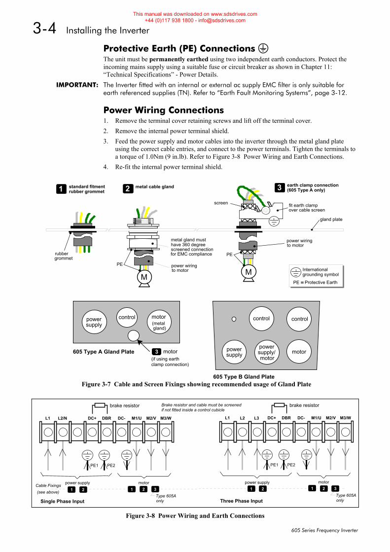
Protective Earth (PE) Connections The unit must be permanently earthed using two independent earth conductors. Protect the incoming mains supply using a suitable fuse or circuit breaker as shown in Chapter 11: “Technical Specifications” - Power Details.
IMPORTANT: The Inverter fitted with an internal or external ac supply EMC filter is only suitable for earth referenced supplies (TN). Refer to “Earth Fault Monitoring Systems”, page 3-12.
Power Wiring Connections 1. Remove the terminal cover retaining screws and lift off the terminal cover. 2. Remove the internal power terminal shield. 3. Feed the power supply and motor cables into the inverter through the metal gland plate
using the correct cable entries, and connect to the power terminals. Tighten the terminals to a torque of 1.0Nm (9 in.lb). Refer to Figure 3-8 Power Wiring and Earth Connections.
4. Re-fit the internal power terminal shield.
PE power wiringto motor
rubbergrommet
metal gland musthave 360 degreescreened connectionfor EMC compliance
M
PE
fit earth clampover cable screen
PE Protective Earth
Internationalgrounding symbolM
power wiringto motor
gland plate
screen
1 standard fitmentrubber grommet 3 earth clamp connection
(605 Type A only)2 metal cable gland
powersupply
control motor(metalgland)
motor
clamp connection)
605 Type A Gland Plate
605 Type B Gland Plate
3(if using earth
control control
powersupply motor
motorpowersupply/
Figure 3-7 Cable and Screen Fixings showing recommended usage of Gland Plate
L1 L2/N DC+ DBR DC- M1/U M2/V M3/W
brake resistor
power supply motor
PE1 PE2
Single Phase Input
L1 L2 DC+ DBR DC- M1/U M2/V M3/W
brake resistor
L3
power supply motor
PE1 PE2
Three Phase Input
1 2 2 3 1 2 2 3
Type 605Aonly
Type 605Aonly
11
Brake resistor and cable must be screenedif not fitted inside a control cubicle
Cable Fixings(see above)
Figure 3-8 Power Wiring and Earth Connections
This manual was downloaded on www.sdsdrives.com +44 (0)117 938 1800 - [email protected]
Installing the Inverter 3-5
605 Series Frequency Inverter
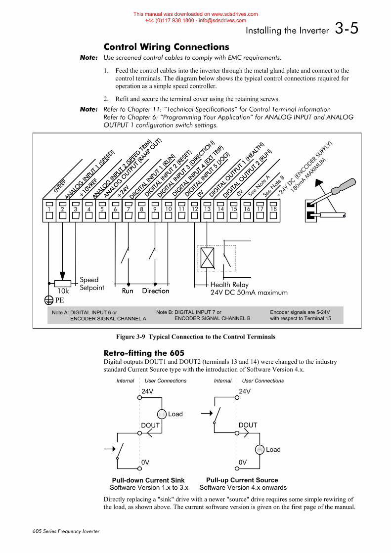
Control Wiring Connections Note: Use screened control cables to comply with EMC requirements.
1. Feed the control cables into the inverter through the metal gland plate and connect to the control terminals. The diagram below shows the typical control connections required for operation as a simple speed controller.
2. Refit and secure the terminal cover using the retaining screws. Note: Refer to Chapter 11: “Technical Specifications” for Control Terminal information
Refer to Chapter 6: “Programming Your Application” for ANALOG INPUT and ANALOG OUTPUT 1 configuration switch settings.
ANAL
OG O
UTPUT (
RAM
P OUT)
1
0VRE
F
2
ANALO
G INPU
T 1 (S
PEED
)
3
+10VR
EF
4
ANALO
G INPU
T 2 (S
PEED
TRIM
)
5 6
+24V
7
DIIGITA
L INPU
T 1 (R
UN)
8
DIGITA
L INPU
T 2 (R
ESET
)
9
DIGITA
L INPU
T 3 (D
IRECTIO
N)
10
DIGITA
L INPU
T 4 (E
XT TR
IP)
11
DIGITA
L INPU
T 5 (J
OG)
12
0V
13
DIGITA
L OUTP
UT 1 (H
EALT
H)
14
DIGITA
L OUTP
UT 2 (R
UN)
15 16 17
See N
ote B
18
+24V
DC (ENCO
DER SU
PPLY
)
10k
SpeedSetpoint Run Direction
Note A: DIGITAL INPUT 5 or ENCODER SIGNAL CHANNEL A
Note B: DIGITAL INPUT 6 or ENCODER SIGNAL CHANNEL B
ANAL
OG O
UTPUT (
RAM
P OUT)
1
0VRE
F
2
ANALO
G INPU
T 1 (S
PEED
)
3
+10VR
EF
4
ANALO
G INPU
T 2 (S
PEED
TRIM
)
5 6
+24V
7
DIIGITA
L INPU
T 1 (R
UN)
8
DIGITA
L INPU
T 2 (R
ESET
)
9
DIGITA
L INPU
T 3 (D
IRECTIO
N)
10
DIGITA
L INPU
T 4 (E
XT TR
IP)
11
DIGITA
L INPU
T 5 (J
OG)
12
0V
13
DIGITA
L OUTP
UT 1 (H
EALT
H)
14
DIGITA
L OUTP
UT 2 (R
UN)
15 16
See N
ote A
17 18
Run DirectionPE
Note A: DIGITAL INPUT 6 or ENCODER SIGNAL CHANNEL A
Note B: DIGITAL INPUT 7 or ENCODER SIGNAL CHANNEL B
Encoder signals are 5-24Vwith respect to Terminal 15
0V
Health Relay24V DC 50mA maximum
180m
A MAX
IMUM
Figure 3-9 Typical Connection to the Control Terminals
Retro-fitting the 605 Digital outputs DOUT1 and DOUT2 (terminals 13 and 14) were changed to the industry standard Current Source type with the introduction of Software Version 4.x.
DOUT
24V
0V
Load
User ConnectionsInternal
Pull-down Current SinkSoftware Version 1.x to 3.x
24V
0V
DOUT
Load
User ConnectionsInternal
Pull-up Current SourceSoftware Version 4.x onwards
Directly replacing a "sink" drive with a newer "source" drive requires some simple rewiring of the load, as shown above. The current software version is given on the first page of the manual.
This manual was downloaded on www.sdsdrives.com +44 (0)117 938 1800 - [email protected]
3-6 Installing the Inverter
605 Series Frequency Inverter
Optional Equipment
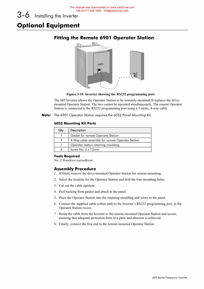
Fitting the Remote 6901 Operator Station
Figure 3-10 Inverter showing the RS232 programming port
The 605 Inverter allows the Operator Station to be remotely-mounted. It replaces the drive-mounted Operator Station. The two cannot be operated simultaneously. The remote Operator Station is connected to the RS232 programming port using a 3 metre, 4-way cable.
Note: The 6901 Operator Station requires the 6052 Panel Mounting Kit.
6052 Mounting Kit Parts
Qty. Description
1 Gasket for remote Operator Station
1 4-Way cable assembly for remote Operator Station
1 Operator station retaining moulding
4 Screw No. 6 x 12mm
Tools Required No. 2 Posidrive screwdriver.
Assembly Procedure 1. If fitted, remove the drive-mounted Operator Station for remote-mounting.
2. Select the location for the Operator Station and drill the four mounting holes.
3. Cut out the cable aperture.
4. Peel backing from gasket and attach to the panel.
5. Place the Operator Station into the retaining moulding and screw to the panel.
6. Connect the supplied cable (either end) to the Inverter’s RS232 programming port, in the Operator Station recess.
7. Route the cable from the Inverter to the remote-mounted Operator Station and secure, ensuring that adequate protection from live parts and abrasion is achieved.
8. Finally, connect the free end to the remote-mounted Operator Station.
This manual was downloaded on www.sdsdrives.com +44 (0)117 938 1800 - [email protected]
Installing the Inverter 3-7
605 Series Frequency Inverter
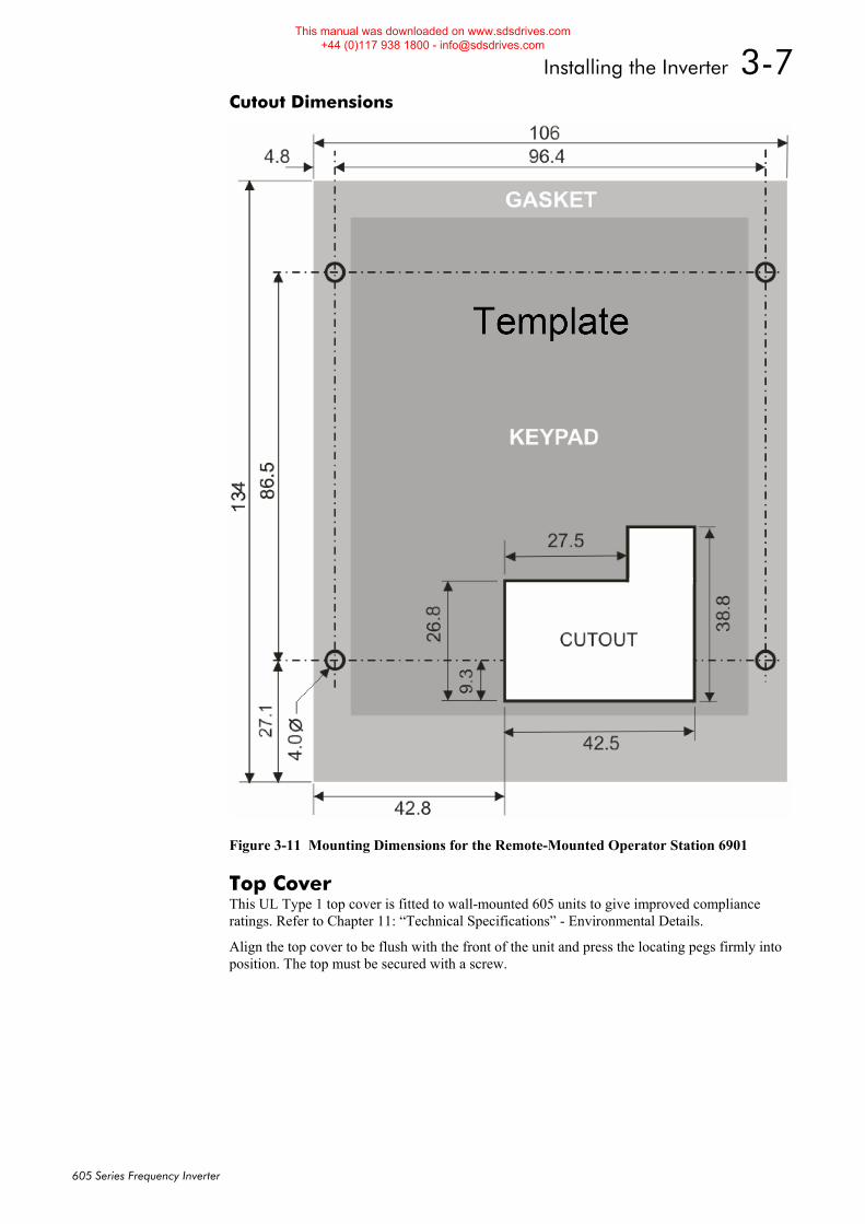
Cutout Dimensions
Figure 3-11 Mounting Dimensions for the Remote-Mounted Operator Station 6901
Top Cover This UL Type 1 top cover is fitted to wall-mounted 605 units to give improved compliance ratings. Refer to Chapter 11: “Technical Specifications” - Environmental Details.
Align the top cover to be flush with the front of the unit and press the locating pegs firmly into position. The top must be secured with a screw.
This manual was downloaded on www.sdsdrives.com +44 (0)117 938 1800 - [email protected]
3-8 Installing the Inverter
605 Series Frequency Inverter
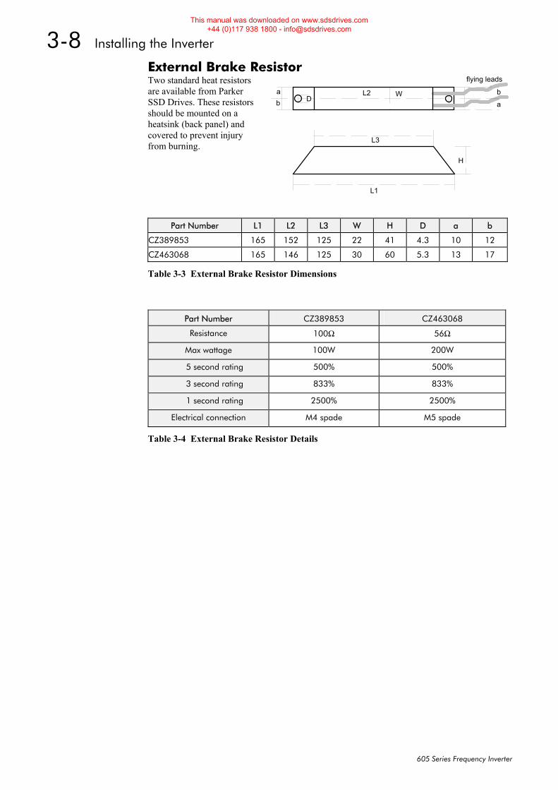
External Brake Resistor Two standard heat resistors are available from Parker SSD Drives. These resistors should be mounted on a heatsink (back panel) and covered to prevent injury from burning.
Table 3-3 External Brake Resistor Dimensions
L1
H
flying leads
L2
L3
Wab a
bD
Part Number L1 L2 L3 W H D a b
CZ389853 165 152 125 22 41 4.3 10 12
CZ463068 165 146 125 30 60 5.3 13 17
Part Number CZ389853 CZ463068
Resistance 100Ω 56Ω
Max wattage 100W 200W
5 second rating 500% 500%
3 second rating 833% 833%
1 second rating 2500% 2500%
Electrical connection M4 spade M5 spade
Table 3-4 External Brake Resistor Details
This manual was downloaded on www.sdsdrives.com +44 (0)117 938 1800 - [email protected]
Installing the Inverter 3-9
605 Series Frequency Inverter
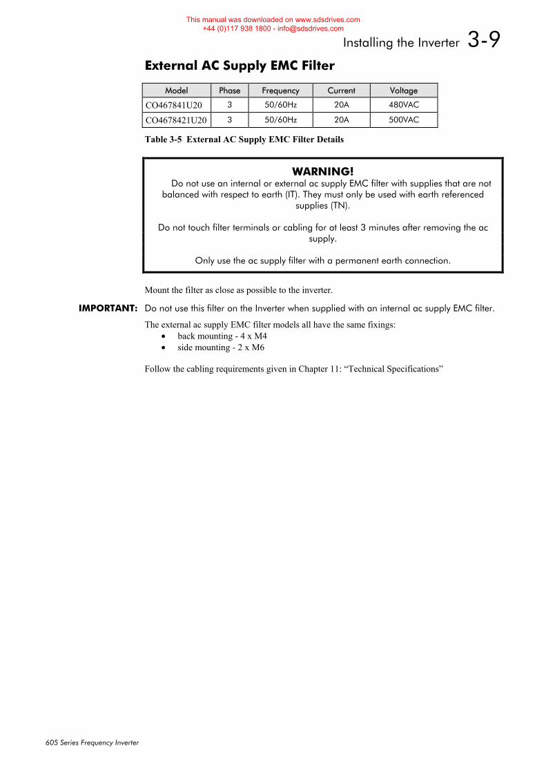
External AC Supply EMC Filter
Table 3-5 External AC Supply EMC Filter Details
WARNING! Do not use an internal or external ac supply EMC filter with supplies that are not
balanced with respect to earth (IT). They must only be used with earth referenced supplies (TN).
Do not touch filter terminals or cabling for at least 3 minutes after removing the ac
supply.
Only use the ac supply filter with a permanent earth connection.
Mount the filter as close as possible to the inverter.
IMPORTANT: Do not use this filter on the Inverter when supplied with an internal ac supply EMC filter.
The external ac supply EMC filter models all have the same fixings: • back mounting - 4 x M4 • side mounting - 2 x M6
Follow the cabling requirements given in Chapter 11: “Technical Specifications”
Model Phase Frequency Current Voltage
CO467841U20 3 50/60Hz 20A 480VAC
CO4678421U20 3 50/60Hz 20A 500VAC
This manual was downloaded on www.sdsdrives.com +44 (0)117 938 1800 - [email protected]
3-10 Installing the Inverter
605 Series Frequency Inverter
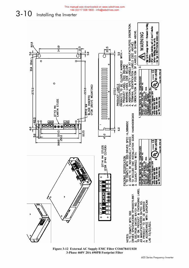
Figure 3-12 External AC Supply EMC Filter CO467841U020 3-Phase 460V 20A 690PB Footprint Filter
This manual was downloaded on www.sdsdrives.com +44 (0)117 938 1800 - [email protected]
Installing the Inverter 3-11
605 Series Frequency Inverter
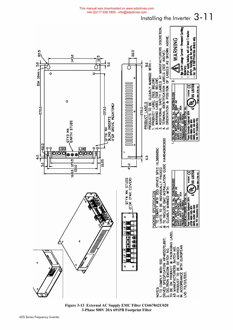
Figure 3-13 External AC Supply EMC Filter CO467842U020 3-Phase 500V 20A 691PB Footprint Filter
This manual was downloaded on www.sdsdrives.com +44 (0)117 938 1800 - [email protected]
3-12 Installing the Inverter
605 Series Frequency Inverter
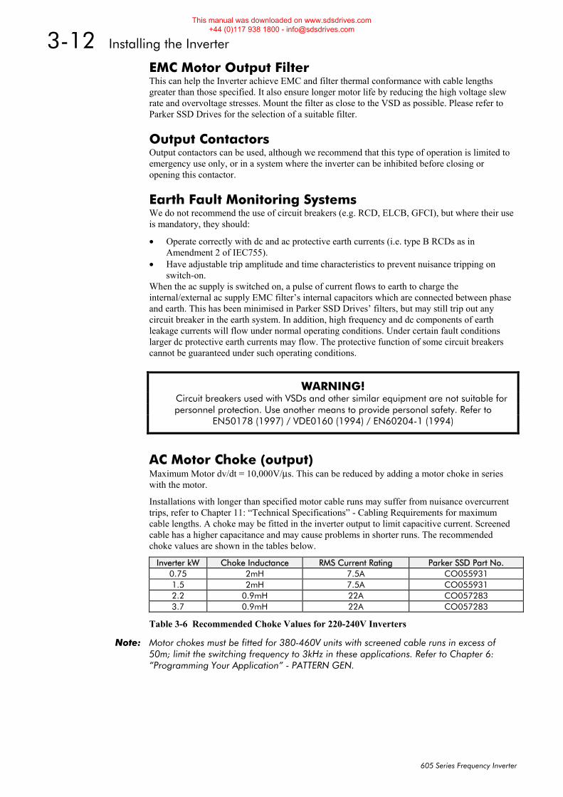
EMC Motor Output Filter This can help the Inverter achieve EMC and filter thermal conformance with cable lengths greater than those specified. It also ensure longer motor life by reducing the high voltage slew rate and overvoltage stresses. Mount the filter as close to the VSD as possible. Please refer to Parker SSD Drives for the selection of a suitable filter.
Output Contactors Output contactors can be used, although we recommend that this type of operation is limited to emergency use only, or in a system where the inverter can be inhibited before closing or opening this contactor.
Earth Fault Monitoring Systems We do not recommend the use of circuit breakers (e.g. RCD, ELCB, GFCI), but where their use is mandatory, they should:
• Operate correctly with dc and ac protective earth currents (i.e. type B RCDs as in Amendment 2 of IEC755).
• Have adjustable trip amplitude and time characteristics to prevent nuisance tripping on switch-on.
When the ac supply is switched on, a pulse of current flows to earth to charge the internal/external ac supply EMC filter’s internal capacitors which are connected between phase and earth. This has been minimised in Parker SSD Drives’ filters, but may still trip out any circuit breaker in the earth system. In addition, high frequency and dc components of earth leakage currents will flow under normal operating conditions. Under certain fault conditions larger dc protective earth currents may flow. The protective function of some circuit breakers cannot be guaranteed under such operating conditions.
WARNING! Circuit breakers used with VSDs and other similar equipment are not suitable for
personnel protection. Use another means to provide personal safety. Refer to EN50178 (1997) / VDE0160 (1994) / EN60204-1 (1994)
AC Motor Choke (output) Maximum Motor dv/dt = 10,000V/μs. This can be reduced by adding a motor choke in series with the motor.
Installations with longer than specified motor cable runs may suffer from nuisance overcurrent trips, refer to Chapter 11: “Technical Specifications” - Cabling Requirements for maximum cable lengths. A choke may be fitted in the inverter output to limit capacitive current. Screened cable has a higher capacitance and may cause problems in shorter runs. The recommended choke values are shown in the tables below.
Inverter kW Choke Inductance RMS Current Rating Parker SSD Part No. 0.75 2mH 7.5A CO055931 1.5 2mH 7.5A CO055931 2.2 0.9mH 22A CO057283 3.7 0.9mH 22A CO057283
Table 3-6 Recommended Choke Values for 220-240V Inverters
Note: Motor chokes must be fitted for 380-460V units with screened cable runs in excess of 50m; limit the switching frequency to 3kHz in these applications. Refer to Chapter 6: “Programming Your Application” - PATTERN GEN.
This manual was downloaded on www.sdsdrives.com +44 (0)117 938 1800 - [email protected]
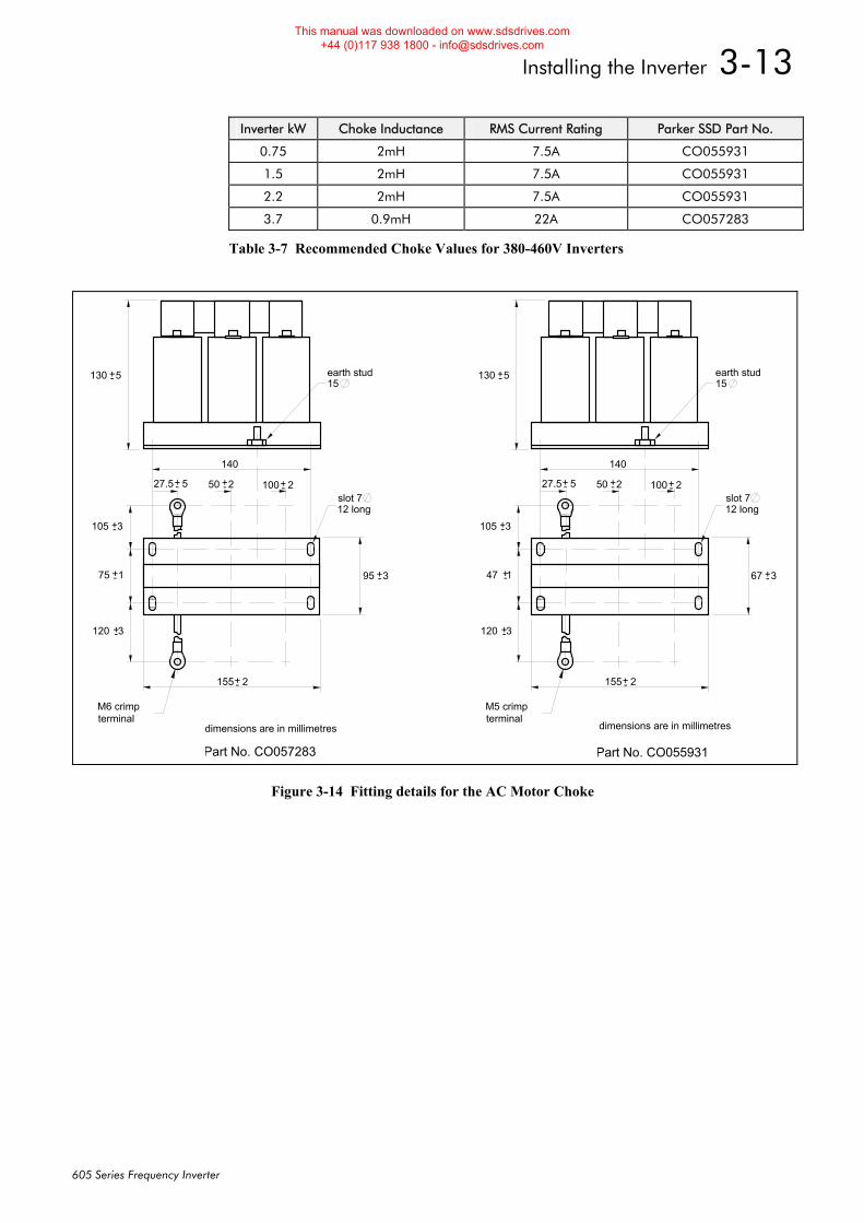
Installing the Inverter 3-13
605 Series Frequency Inverter
Inverter kW Choke Inductance RMS Current Rating Parker SSD Part No.
0.75 2mH 7.5A CO055931
1.5 2mH 7.5A CO055931
2.2 2mH 7.5A CO055931
3.7 0.9mH 22A CO057283
Table 3-7 Recommended Choke Values for 380-460V Inverters
130 5+-
105 3+-
120 3+-
75 1+-
27.5 5+- 50 2+- 100 2+-
95 3+-
155 2+-
140
M6 crimpterminal
15 earth stud
slot 712 long
Eurotherm Part No. CO057283
M5 crimpterminal
130 5+-
105 3+-
120 3+-
47 1+-
27.5 5+- 50 2+- 100 2+-
67 3+-
155 2+-
140
15 earth stud
slot 712 long
Eurotherm Part No. CO055931
dimensions are in millimetres dimensions are in millimetres
Figure 3-14 Fitting details for the AC Motor Choke
This manual was downloaded on www.sdsdrives.com +44 (0)117 938 1800 - [email protected]

3-14 Installing the Inverter
605 Series Frequency Inverter
This manual was downloaded on www.sdsdrives.com +44 (0)117 938 1800 - [email protected]
Operating the Inverter 4-1
605 Series Frequency Inverter
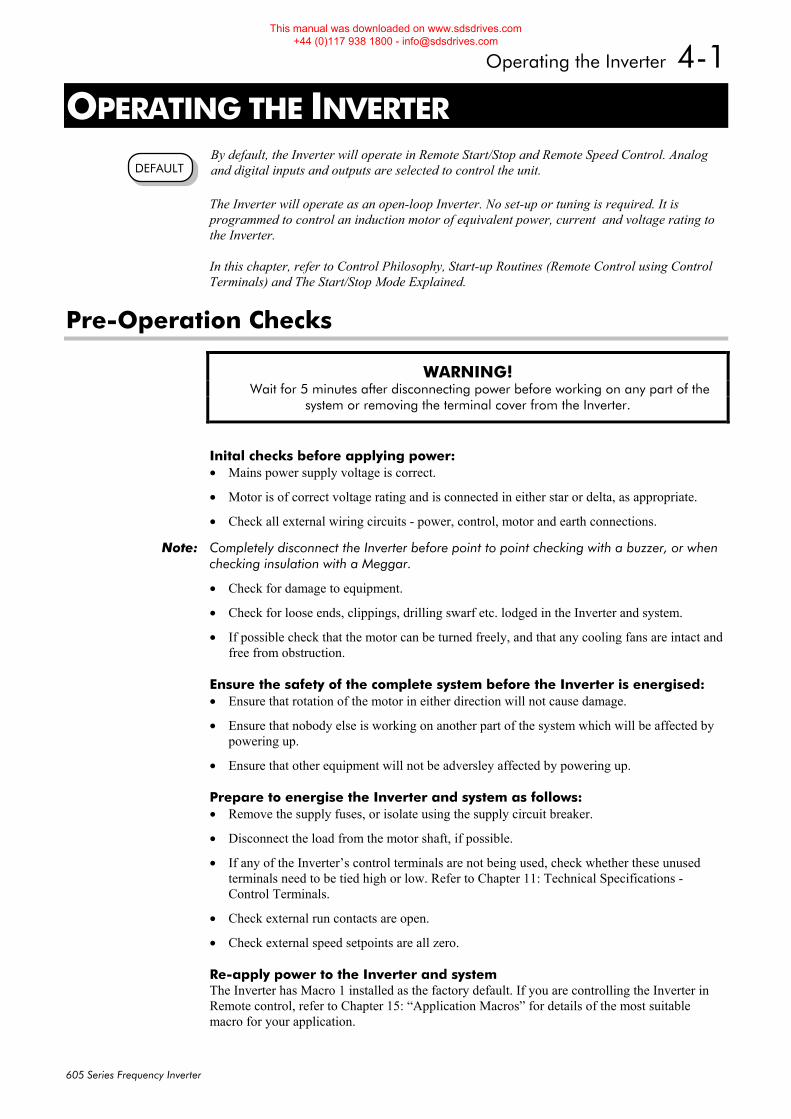
4OPERATING THE INVERTER By default, the Inverter will operate in Remote Start/Stop and Remote Speed Control. Analog and digital inputs and outputs are selected to control the unit.
The Inverter will operate as an open-loop Inverter. No set-up or tuning is required. It is programmed to control an induction motor of equivalent power, current and voltage rating to the Inverter.
In this chapter, refer to Control Philosophy, Start-up Routines (Remote Control using Control Terminals) and The Start/Stop Mode Explained.
Pre-Operation Checks
WARNING! Wait for 5 minutes after disconnecting power before working on any part of the
system or removing the terminal cover from the Inverter.
Inital checks before applying power: • Mains power supply voltage is correct.
• Motor is of correct voltage rating and is connected in either star or delta, as appropriate.
• Check all external wiring circuits - power, control, motor and earth connections.
Note: Completely disconnect the Inverter before point to point checking with a buzzer, or when checking insulation with a Meggar.
• Check for damage to equipment.
• Check for loose ends, clippings, drilling swarf etc. lodged in the Inverter and system.
• If possible check that the motor can be turned freely, and that any cooling fans are intact and free from obstruction.
Ensure the safety of the complete system before the Inverter is energised: • Ensure that rotation of the motor in either direction will not cause damage.
• Ensure that nobody else is working on another part of the system which will be affected by powering up.
• Ensure that other equipment will not be adversley affected by powering up.
Prepare to energise the Inverter and system as follows: • Remove the supply fuses, or isolate using the supply circuit breaker.
• Disconnect the load from the motor shaft, if possible.
• If any of the Inverter’s control terminals are not being used, check whether these unused terminals need to be tied high or low. Refer to Chapter 11: Technical Specifications - Control Terminals.
• Check external run contacts are open.
• Check external speed setpoints are all zero.
Re-apply power to the Inverter and system The Inverter has Macro 1 installed as the factory default. If you are controlling the Inverter in Remote control, refer to Chapter 15: “Application Macros” for details of the most suitable macro for your application.
DEFAULT
This manual was downloaded on www.sdsdrives.com +44 (0)117 938 1800 - [email protected]
4-2 Operating the Inverter
605 Series Frequency Inverter
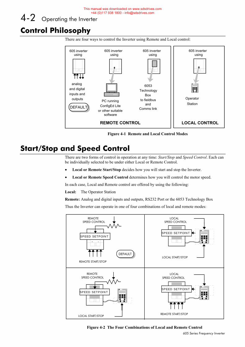
Control Philosophy There are four ways to control the Inverter using Remote and Local control:
Start/Stop and Speed Control There are two forms of control in operation at any time: Start/Stop and Speed Control. Each can be individually selected to be under either Local or Remote Control.
• Local or Remote Start/Stop decides how you will start and stop the Inverter.
• Local or Remote Speed Control determines how you will control the motor speed.
In each case, Local and Remote control are offered by using the following:
Local: The Operator Station
Remote: Analog and digital inputs and outputs, RS232 Port or the 6053 Technology Box
Thus the Inverter can operate in one of four combinations of local and remote modes:
analogand digitalinputs and
outputs PC runningConfigEd Lite
or other suitablesoftware
Technology
REMOTE CONTROL
605 inverterusing
605 inverterusing
605 inverterusing
LOCAL CONTROL
605 inverterusing
Box
6053
to fieldbusand
Comms link
OperatorStation
DEFAULT
Figure 4-1 Remote and Local Control Modes
REMOTE START/STOP
SPEED SETPOINT
REMOTE
LOCAL START/STOP
SPEED SETPOINT
LOCAL
REMOTE START/STOP
SPEED SETPOINT
LOCAL
LOCAL START/STOP
REMOTE
SPEED SETPOINT
SPEED CONTROL
SPEED CONTROL
SPEED CONTROL
SPEED CONTROL
DEFAULT
Figure 4-2 The Four Combinations of Local and Remote Control
This manual was downloaded on www.sdsdrives.com +44 (0)117 938 1800 - [email protected]
Operating the Inverter 4-3
605 Series Frequency Inverter
Note: Start/Stop is also known as “Sequencing”.
Speed Control is also known as “Reference Generation”.
Selecting Local or Remote Control If the default combination of remote Start/Stop and Speed Control is not suitable for your application, follow the instructions below using the Operator Station or a suitable PC programming tool to select suitable combinations of local or remote control.
Note: You can only change between Local and Remote control when the Inverter is “stopped”.
To change a combination the Operator Station must have the “Advanced” viewing level selected; allowing you to view enough of the menu structure to make the change. Refer to Chapter 5: “ The Operator Station” - Menu Viewing Levels.
The L/R key on the Operator Station toggles between Local and Remote control, changing both Start/Stop and Speed Control modes at the same time.
However, you can “fix” either or both modes in software to be either Local or Remote control. This makes the L/R key inoperative for that mode. In this way, you can select a combination where both Local and Remote modes are present.
To do this, go to the LOCAL CONTROL menu at level 4 and select either:
LOCAL ONLY Sets Local control
REMOTE ONLY Sets Remote control
LOCAL/REMOTE Gives selection powers back to the L/R key.
Fixing only one of the modes will mean that the L/R key will still toggle the other mode between Local and Remote control.
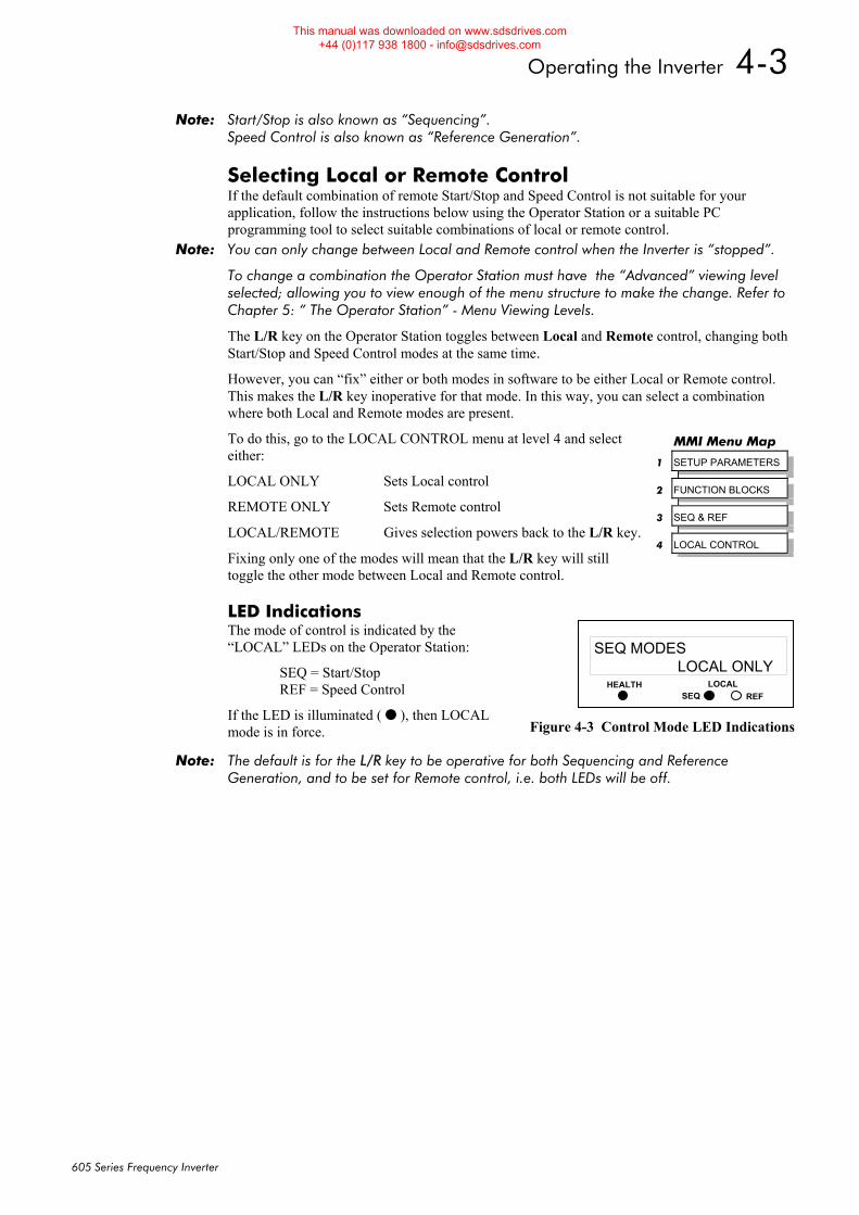
LED Indications The mode of control is indicated by the “LOCAL” LEDs on the Operator Station:
SEQ = Start/Stop REF = Speed Control
If the LED is illuminated ( ), then LOCAL mode is in force.
Note: The default is for the L/R key to be operative for both Sequencing and Reference Generation, and to be set for Remote control, i.e. both LEDs will be off.
MMI Menu Map
1 SETUP PARAMETERS
2 FUNCTION BLOCKS
3 SEQ & REF
4 LOCAL CONTROL
HEALTH LOCALSEQ REF
SEQ MODESLOCAL ONLY
Figure 4-3 Control Mode LED Indications
This manual was downloaded on www.sdsdrives.com +44 (0)117 938 1800 - [email protected]
4-4 Operating the Inverter
605 Series Frequency Inverter
Start-up Routines
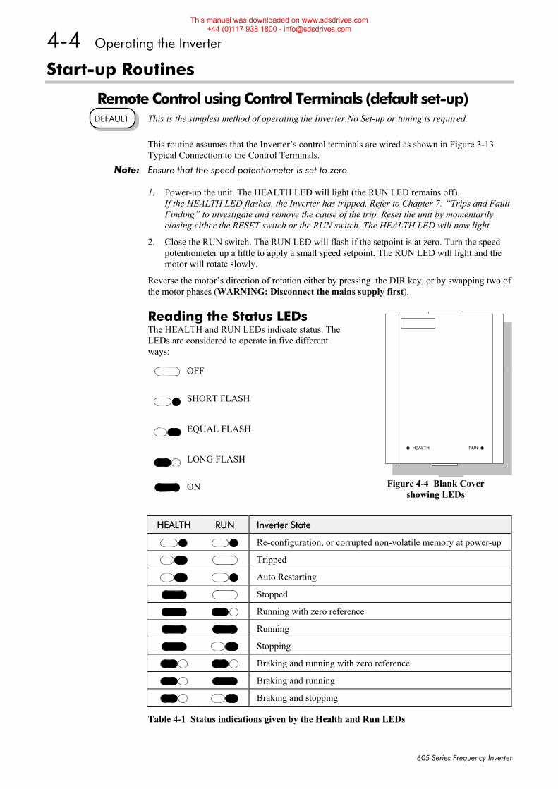
Remote Control using Control Terminals (default set-up) This is the simplest method of operating the Inverter.No Set-up or tuning is required. This routine assumes that the Inverter’s control terminals are wired as shown in Figure 3-13 Typical Connection to the Control Terminals.
Note: Ensure that the speed potentiometer is set to zero.
1. Power-up the unit. The HEALTH LED will light (the RUN LED remains off). If the HEALTH LED flashes, the Inverter has tripped. Refer to Chapter 7: “Trips and Fault Finding” to investigate and remove the cause of the trip. Reset the unit by momentarily closing either the RESET switch or the RUN switch. The HEALTH LED will now light.
2. Close the RUN switch. The RUN LED will flash if the setpoint is at zero. Turn the speed potentiometer up a little to apply a small speed setpoint. The RUN LED will light and the motor will rotate slowly.
Reverse the motor’s direction of rotation either by pressing the DIR key, or by swapping two of the motor phases (WARNING: Disconnect the mains supply first).
Reading the Status LEDs The HEALTH and RUN LEDs indicate status. The LEDs are considered to operate in five different ways:
OFF
SHORT FLASH
EQUAL FLASH
LONG FLASH
ON
Table 4-1 Status indications given by the Health and Run LEDs
DEFAULT
RUNHEALTH
Figure 4-4 Blank Cover
showing LEDs
HEALTH RUN Inverter State
Re-configuration, or corrupted non-volatile memory at power-up
Tripped
Auto Restarting
Stopped
Running with zero reference
Running
Stopping
Braking and running with zero reference
Braking and running
Braking and stopping
This manual was downloaded on www.sdsdrives.com +44 (0)117 938 1800 - [email protected]
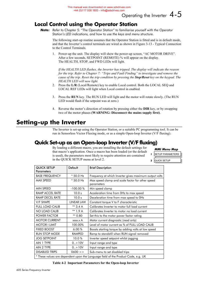
Operating the Inverter 4-5
605 Series Frequency Inverter
Local Control using the Operator Station Note: Refer to Chapter 5: “The Operator Station” to familiarise yourself with the Operator
Station’s LED indications, and how to use the keys and menu structure.
The following start-up routine assumes that the Operator Station is fitted and is in default mode, and that the Inverter’s control terminals are wired as shown in Figure 3-13 - Typical Connection to the Control Terminals.
1. Power-up the unit. The display will show the power-up screen, “AC MOTOR DRIVE”. After a few seconds, SETPOINT (REMOTE) % will appear on the display. The HEALTH, STOP, and FWD LEDs will light. If the HEALTH LED flashes, the Inverter has tripped. The display will indicate the reason for the trip. Refer to Chapter 7: “Trips and Fault Finding” to investigate and remove the cause of the trip. Reset the trip condition by pressing the Stop/Reset key on the keypad. The HEALTH LED will now light.
2. Press the L/R (Local/Remote) key to enable Local control. Both the LOCAL SEQ and LOCAL REF LEDs will light when Local control in enabled.
3. Press the RUN key. The RUN LED will light and the motor will rotate slowly. (The RUN
LED would flash if the setpoint was at zero.)
4. Reverse the motor’s direction of rotation by pressing either the DIR key, or by swapping two of the motor phases (WARNING: Disconnect the mains supply first).
Setting-up the Inverter The Inverter is set-up using the Operator Station, or a suitable PC programming tool. It can be run in Sensorless Vector Fluxing mode, or as a simple Open-loop Inverter (V/F fluxing).
Quick Set-up as an Open-loop Inverter (V/F fluxing) By loading a different macro, you are installing the default settings for that macro’s application. Once a macro has been loaded (or the default is used), the parameters most likely to require attention are contained in the QUICK SETUP menu at level 2.
QUICK SETUP Parameters
Default Brief Description
BASE FREQUENCY * 50.0 Hz Frequency at which Inverter gives maximum output volts
MAX SPEED * 50.0 Hz Max speed clamp and scale factor for other speed parameters
MIN SPEED -100.00 % Min speed clamp
RAMP ACCEL RATE 10.0 s Acceleration time from 0Hz to max speed
RAMP DECEL RATE 10.0 s Deceleration time from max speed to 0Hz
V/F SHAPE LINEAR LAW Constant torque V to F characteristic
FULL LOAD CALIB ** 3.4 A Calibrates Inverter to motor full load current
NO LOAD CALIB ** 1.9 A Calibrates Inverter to motor no load current
POWER FACTOR ** 0.80 Set this to the motor power factor rating
MOTOR CURRENT xxxx.x A Motor current diagnostic (read only)
MOTOR I LIMIT 100.00% Level of motor current as % of FULL LOAD CALIB
FIXED BOOST 6.00 % Boosts starting torque by adding volts at low speed
RUN STOP MODE RAMPED Ramp to standstill when RUN signal removed
JOG SETPOINT 10.0 % Inverter speed setpoint whilst jogging
AIN 1 TYPE 0..+10V Input range and type
AIN 2 TYPE 0..+10V Input range and type
DISABLED TRIPS 0600 >> Sub-menu to set disabled trips
* These values are dependent upon the Language field of the Product Code, e.g. UK
Table 4-2 Important Parameters for the Open-loop Inverter
MMI Menu Map
1 SETUP PARAMETERS
2 QUICK SETUP
This manual was downloaded on www.sdsdrives.com +44 (0)117 938 1800 - [email protected]
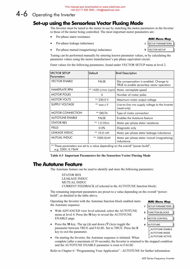
4-6 Operating the Inverter
605 Series Frequency Inverter
Set-up using the Sensorless Vector Fluxing Mode The Inverter must be tuned to the motor in use by matching the motor parameters in the Inverter to those of the motor being controlled. The most important motor parameters are: • Per-phase stator resistance
• Per-phase leakage inductance
• Per-phase mutual (magnetising) inductance
Tuning can be performed manually by entering known parameter values, or by calculating the parameter values using the motor manufacturer’s per-phase equivalent circuit.
Enter values for the following parameters, found under VECTOR SETUP menu at level 2.
VECTOR SETUP Parameters
Default Brief Description
VECTOR ENABLE FALSE Slip compensation is enabled. Change to TRUE to enable sensorless vector operation
NAMEPLATE RPM ** 1420 n/min (rpm) Motor nameplate speed
MOTOR POLES 4 Number of motor poles
MOTOR VOLTS ** 230.0 V Maximum motor output voltage
SUPPLY VOLTAGE ** xxxx.x V Line-to-line rms supply voltage to the Inverter (read-only)
MOTOR CONNECTION ** DELTA Type of motor connection
AUTOTUNE ENABLE FALSE Enables the Autotune feature
STATOR RES ** 1.0 Ohm Motor per-phase stator resistance
FIELD 0.0% Diagnostic only
LEAKAGE INDUC ** 10.0 mH Motor per-phase stator leakage inductance
MUTUAL INDUC ** 1000.0mH Motor per-phase stator mutual (magnetising) inductance
** These parameters are set to a value depending on the overall “power-build”, e.g. 230V, 0.75kW
Table 4-3 Important Parameters for the Sensorless Vector Fluxing Mode
The Autotune Feature The Autotune feature can be used to identify and store the following parameters:
STATOR RES LEAKAGE INDUC MUTUAL INDUC CURRENT FEEDBACK (if selected in the AUTOTUNE function block)
The remaining important parameters are preset to a value depending on the overall “power-build”, as detailed in the table above.
Operating the Inverter with the Autotune function block enabled starts the Autotune sequence.
• With ADVANCED view level selected, select the AUTOTUNE menu at level 4. Press the M key to reveal the AUTOTUNE ENABLE page.
• Press the M key. The up (Δ) and down (∇) keys toggle the parameter between TRUE and FALSE. Set to TRUE. Press the E key to exit the parameter.
• On starting the Inverter, the Autotune sequence is initiated. When complete (after a maximum of 10 seconds), the Inverter is returned to the stopped condition and the AUTOTUNE ENABLE parameter is reset to FALSE.
Refer to Chapter 6: “Programming Your Application” - AUTOTUNE for further information.
MMI Menu Map
1 SETUP PARAMETERS
2 VECTOR SETUP
MMI Menu Map
1 SETUP PARAMETERS
2 FUNCTION BLOCKS
3 MOTOR CONTROL
4 AUTOTUNE
AUTOTUNE ENABLE
AUTOTUNE MODE
AUTOTUNE ACTIVE
This manual was downloaded on www.sdsdrives.com +44 (0)117 938 1800 - [email protected]
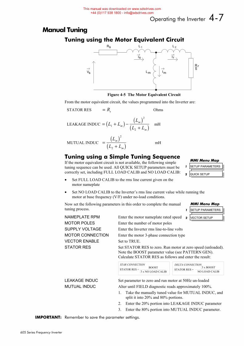
Operating the Inverter 4-7
605 Series Frequency Inverter
Manual Tuning Tuning using the Motor Equivalent Circuit
V
I
I
I
R L
L
L
RS
1
m m
2s
s r
s
r
Figure 4-5 The Motor Equivalent Circuit
From the motor equivalent circuit, the values programmed into the Inverter are:
STATOR RES = Rs Ohms
LEAKAGE INDUC ( ) ( )( )= + −
+L L
LL Lm
m
m1
2
2
mH
MUTUAL INDUC ( )
( )=+
LL L
m
m
2
2
mH
Tuning using a Simple Tuning Sequence If the motor equivalent circuit is not available, the following simple tuning sequence can be used. All QUICK SETUP parameters must be correctly set, including FULL LOAD CALIB and NO LOAD CALIB:
• Set FULL LOAD CALIB to the rms line current given on the motor nameplate
• Set NO LOAD CALIB to the Inverter’s rms line current value while running the motor at base frequency (V/F) under no-load conditions.
Now set the following parameters in this order to complete the manual tuning process.
NAMEPLATE RPM Enter the motor nameplate rated speed MOTOR POLES Enter the number of motor poles SUPPLY VOLTAGE Enter the Inverter rms line-to-line volts MOTOR CONNECTION Enter the motor 3-phase connection type VECTOR ENABLE Set to TRUE. STATOR RES Set STATOR RES to zero. Run motor at zero speed (unloaded). Note the BOOST parameter value (see PATTERN GEN). Calculate STATOR RES as follows and enter the result:
STATOR RES = BOOST
3 x NO LOAD CALIB
STAR CONNECTION
STATOR RES = NO LOAD CALIB
DELTA CONNECTION3 x BOOST
LEAKAGE INDUC Set parameter to zero and run motor at 50Hz un-loaded MUTUAL INDUC Alter until FIELD diagnostic reads approximately 100%.
1. Take the manually tuned value for MUTUAL INDUC, and split it into 20% and 80% portions.
2. Enter the 20% portion into LEAKAGE INDUC parameter 3. Enter the 80% portion into MUTUAL INDUC parameter.
IMPORTANT: Remember to save the parameter settings.
MMI Menu Map
1 SETUP PARAMETERS
2 QUICK SETUP
MMI Menu Map
1 SETUP PARAMETERS
2 VECTOR SETUP
This manual was downloaded on www.sdsdrives.com +44 (0)117 938 1800 - [email protected]
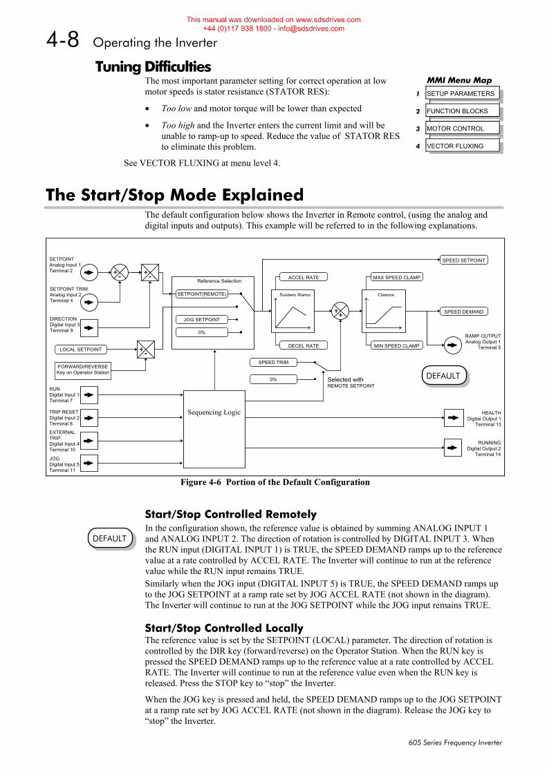
4-8 Operating the Inverter
605 Series Frequency Inverter
Tuning Difficulties The most important parameter setting for correct operation at low motor speeds is stator resistance (STATOR RES):
• Too low and motor torque will be lower than expected
• Too high and the Inverter enters the current limit and will be unable to ramp-up to speed. Reduce the value of STATOR RES to eliminate this problem.
See VECTOR FLUXING at menu level 4.
The Start/Stop Mode Explained The default configuration below shows the Inverter in Remote control, (using the analog and digital inputs and outputs). This example will be referred to in the following explanations.
Start/Stop Controlled Remotely In the configuration shown, the reference value is obtained by summing ANALOG INPUT 1 and ANALOG INPUT 2. The direction of rotation is controlled by DIGITAL INPUT 3. When the RUN input (DIGITAL INPUT 1) is TRUE, the SPEED DEMAND ramps up to the reference value at a rate controlled by ACCEL RATE. The Inverter will continue to run at the reference value while the RUN input remains TRUE. Similarly when the JOG input (DIGITAL INPUT 5) is TRUE, the SPEED DEMAND ramps up to the JOG SETPOINT at a ramp rate set by JOG ACCEL RATE (not shown in the diagram). The Inverter will continue to run at the JOG SETPOINT while the JOG input remains TRUE.
Start/Stop Controlled Locally The reference value is set by the SETPOINT (LOCAL) parameter. The direction of rotation is controlled by the DIR key (forward/reverse) on the Operator Station. When the RUN key is pressed the SPEED DEMAND ramps up to the reference value at a rate controlled by ACCEL RATE. The Inverter will continue to run at the reference value even when the RUN key is released. Press the STOP key to “stop” the Inverter.
When the JOG key is pressed and held, the SPEED DEMAND ramps up to the JOG SETPOINT at a ramp rate set by JOG ACCEL RATE (not shown in the diagram). Release the JOG key to “stop” the Inverter.
MMI Menu Map
1 SETUP PARAMETERS
2 FUNCTION BLOCKS
3 MOTOR CONTROL
4 VECTOR FLUXING
DEFAULT
SETPOINTAnalog Input 1Terminal 2
SETPOINT TRIMAnalog Input 2Terminal 4
RUNDigital Input 1Terminal 7
TRIP RESETDigital Input 2Terminal 8
DIRECTIONDigital Input 3Terminal 9
JOGDigital Input 5Terminal 11
+-
+- MAX SPEED CLAMP
MIN SPEED CLAMP
System Ramp Clamps
DECEL RATE
ACCEL RATE
Sequencing Logic
Reference Selection
SETPOINT(REMOTE)
LOCAL SETPOINT
JOG SETPOINT
0%
HEALTHDigital Output 1
Terminal 13
RUNNINGDigital Output 2
Terminal 14
RAMP OUTPUTAnalog Output 1
Terminal 5
++
SPEED TRIM
SPEED DEMAND
FORWARD/REVERSEKey on Operator Station
+-
SPEED SETPOINT
0% Selected withREMOTE SETPOINT
EXTERNALTRIPDigital Input 4Terminal 10
Figure 4-6 Portion of the Default Configuration
DEFAULT
This manual was downloaded on www.sdsdrives.com +44 (0)117 938 1800 - [email protected]
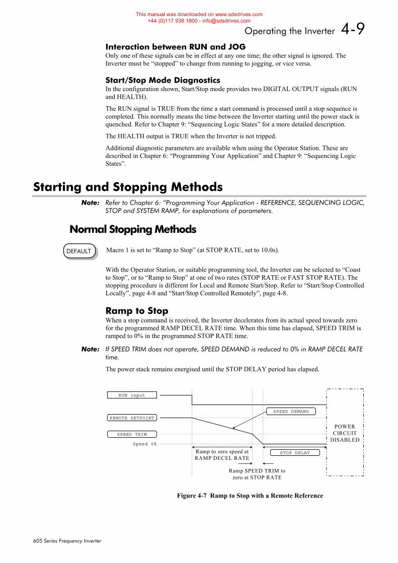
Operating the Inverter 4-9
605 Series Frequency Inverter
Interaction between RUN and JOG Only one of these signals can be in effect at any one time; the other signal is ignored. The Inverter must be “stopped” to change from running to jogging, or vice versa.
Start/Stop Mode Diagnostics In the configuration shown, Start/Stop mode provides two DIGITAL OUTPUT signals (RUN and HEALTH).
The RUN signal is TRUE from the time a start command is processed until a stop sequence is completed. This normally means the time between the Inverter starting until the power stack is quenched. Refer to Chapter 9: “Sequencing Logic States” for a more detailed description.
The HEALTH output is TRUE when the Inverter is not tripped.
Additional diagnostic parameters are available when using the Operator Station. These are described in Chapter 6: “Programming Your Application” and Chapter 9: “Sequencing Logic States”.
Starting and Stopping Methods Note: Refer to Chapter 6: “Programming Your Application - REFERENCE, SEQUENCING LOGIC,
STOP and SYSTEM RAMP, for explanations of parameters.
Normal Stopping Methods Macro 1 is set to “Ramp to Stop” (at STOP RATE, set to 10.0s).
With the Operator Station, or suitable programming tool, the Inverter can be selected to “Coast to Stop”, or to “Ramp to Stop” at one of two rates (STOP RATE or FAST STOP RATE). The stopping procedure is different for Local and Remote Start/Stop. Refer to “Start/Stop Controlled Locally”, page 4-8 and “Start/Stop Controlled Remotely”, page 4-8.
Ramp to Stop When a stop command is received, the Inverter decelerates from its actual speed towards zero for the programmed RAMP DECEL RATE time. When this time has elapsed, SPEED TRIM is ramped to 0% in the programmed STOP RATE time.
Note: If SPEED TRIM does not operate, SPEED DEMAND is reduced to 0% in RAMP DECEL RATE time.
The power stack remains energised until the STOP DELAY period has elapsed.
DEFAULT
SPEED DEMAND
REMOTE SETPOINT
Speed 0%
RUN input
Ramp to zero speed atRAMP DECEL RATE
Ramp SPEED TRIM tozero at STOP RATE
SPEED TRIM
POWERCIRCUIT
DISABLED
STOP DELAY
Figure 4-7 Ramp to Stop with a Remote Reference
This manual was downloaded on www.sdsdrives.com +44 (0)117 938 1800 - [email protected]
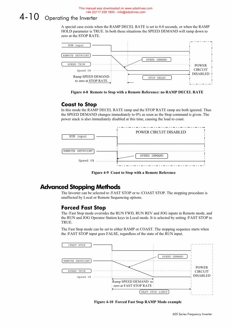
4-10 Operating the Inverter
605 Series Frequency Inverter
A special case exists when the RAMP DECEL RATE is set to 0.0 seconds, or when the RAMP HOLD parameter is TRUE. In both these situations the SPEED DEMAND will ramp down to zero at the STOP RATE.
Coast to Stop In this mode the RAMP DECEL RATE ramp and the STOP RATE ramp are both ignored. Thus the SPEED DEMAND changes immediately to 0% as soon as the Stop command is given. The power stack is also immediately disabled at this time, causing the load to coast.
Advanced Stopping Methods The Inverter can be selected to /FAST STOP or to /COAST STOP. The stopping procedure is unaffected by Local or Remote Sequencing options.
Forced Fast Stop The /Fast Stop mode overrides the RUN FWD, RUN REV and JOG inputs in Remote mode, and the RUN and JOG Operator Station keys in Local mode. It is selected by setting /FAST STOP to TRUE.
The Fast Stop mode can be set to either RAMP or COAST. The stopping sequence starts when the /FAST STOP input goes FALSE, regardless of the state of the RUN input.
SPEED DEMAND
REMOTE SETPOINT
Speed 0%
RUN input
Ramp SPEED DEMANDto zero at STOP RATE
SPEED TRIM POWERCIRCUIT
DISABLEDSTOP DELAY
Figure 4-8 Remote to Stop with a Remote Reference: no RAMP DECEL RATE
POWER CIRCUIT DISABLED
SPEED DEMAND
REMOTE SETPOINT
Speed 0%
RUN input
Figure 4-9 Coast to Stop with a Remote Reference
SPEED DEMAND
REMOTE SETPOINT
Speed 0%
Ramp SPEED DEMAND tozero at FAST STOP RATE
SPEED TRIMPOWER
CIRCUITDISABLED
FAST STOP LIMIT
/FAST STOP
Figure 4-10 Forced Fast Stop RAMP Mode example
This manual was downloaded on www.sdsdrives.com +44 (0)117 938 1800 - [email protected]
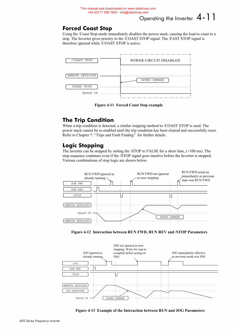
Operating the Inverter 4-11
605 Series Frequency Inverter
Forced Coast Stop Using the /Coast Stop mode immediately disables the power stack, causing the load to coast to a stop. The Inverter gives priority to the /COAST STOP signal. The /FAST STOP signal is therefore ignored while /COAST STOP is active.
The Trip Condition When a trip condition is detected, a similar stopping method to /COAST STOP is used. The power stack cannot be re-enabled until the trip condition has been cleared and successfully reset. Refer to Chapter 7: “Trips and Fault Finding” for further details.
Logic Stopping The Inverter can be stopped by setting the /STOP to FALSE for a short time, (>100 ms). The stop sequence continues even if the /STOP signal goes inactive before the Inverter is stopped. Various combinations of stop logic are shown below.
POWER CIRCUIT DISABLED
SPEED DEMAND
REMOTE SETPOINT
Speed 0%
SPEED TRIM
/COAST STOP
Figure 4-11 Forced Coast Stop example
SPEED DEMAND
REMOTE SETPOINT
Speed 0%
RUN FWD
/STOP
REMOTE SETPOINT
RUN REV
RUN FWD ignored asalready running
RUN FWD acted onimmediately as previousstate was RUN FWD
RUN FWD not ignoredas now stopping
Figure 4-12 Interaction between RUN FWD, RUN REV and /STOP Parameters
SPEED DEMAND
JOG SETPOINT
Speed 0%
RUN FWD
/STOP
REMOTE SETPOINT
JOG
JOG ignored asalready running
JOG immediately effectiveas previous mode was JOG
JOG not ignored as nowstopping. Waits for stop tocomplete before acting onJOG.
Figure 4-13 Example of the Interaction between RUN and JOG Parameters
This manual was downloaded on www.sdsdrives.com +44 (0)117 938 1800 - [email protected]
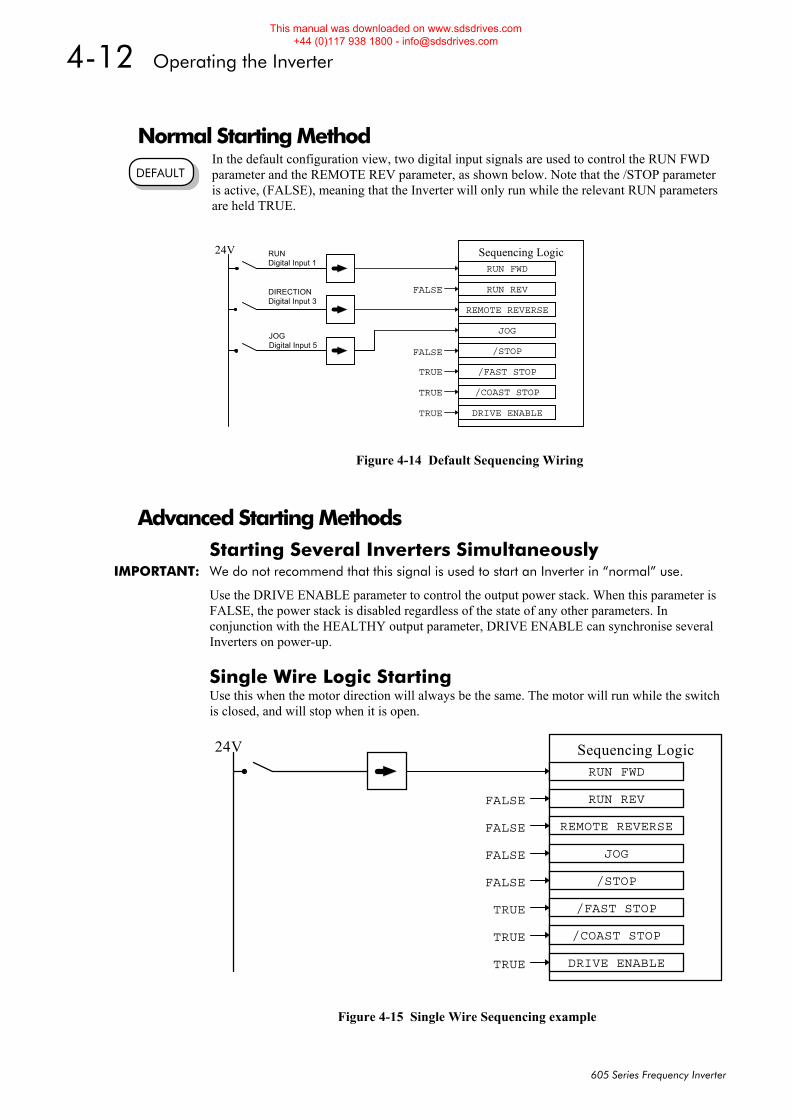
4-12 Operating the Inverter
605 Series Frequency Inverter
Normal Starting Method In the default configuration view, two digital input signals are used to control the RUN FWD parameter and the REMOTE REV parameter, as shown below. Note that the /STOP parameter is active, (FALSE), meaning that the Inverter will only run while the relevant RUN parameters are held TRUE.
Advanced Starting Methods Starting Several Inverters Simultaneously
IMPORTANT: We do not recommend that this signal is used to start an Inverter in “normal” use.
Use the DRIVE ENABLE parameter to control the output power stack. When this parameter is FALSE, the power stack is disabled regardless of the state of any other parameters. In conjunction with the HEALTHY output parameter, DRIVE ENABLE can synchronise several Inverters on power-up.
Single Wire Logic Starting Use this when the motor direction will always be the same. The motor will run while the switch is closed, and will stop when it is open.
DEFAULT
RUNDigital Input 1
DIRECTIONDigital Input 3
JOGDigital Input 5
Sequencing LogicRUN FWD
REMOTE REVERSE
JOG
RUN REVFALSE
/STOP
/FAST STOP
/COAST STOP
DRIVE ENABLE
FALSE
TRUE
TRUE
TRUE
24V
Figure 4-14 Default Sequencing Wiring
Sequencing LogicRUN FWD
REMOTE REVERSE
JOG
RUN REVFALSE
/STOP
/FAST STOP
/COAST STOP
DRIVE ENABLE
FALSE
TRUE
TRUE
TRUE
24V
FALSE
FALSE
Figure 4-15 Single Wire Sequencing example
This manual was downloaded on www.sdsdrives.com +44 (0)117 938 1800 - [email protected]
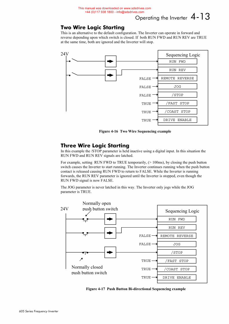
Operating the Inverter 4-13
605 Series Frequency Inverter
Two Wire Logic Starting This is an alternative to the default configuration. The Inverter can operate in forward and reverse depending upon which switch is closed. If both RUN FWD and RUN REV are TRUE at the same time, both are ignored and the Inverter will stop.
Three Wire Logic Starting In this example the /STOP parameter is held inactive using a digital input. In this situation the RUN FWD and RUN REV signals are latched.
For example, setting RUN FWD to TRUE temporarily, (> 100ms), by closing the push button switch causes the Inverter to start running. The Inverter continues running when the push button contact is released causing RUN FWD to return to FALSE. While the Inverter is running forwards, the RUN REV parameter is ignored until the Inverter is stopped, even though the RUN FWD signal is now FALSE.
The JOG parameter is never latched in this way. The Inverter only jogs while the JOG parameter is TRUE.
Sequencing LogicRUN FWD
REMOTE REVERSE
JOG
RUN REV
/STOP
/FAST STOP
/COAST STOP
DRIVE ENABLE
FALSE
TRUE
TRUE
TRUE
24V
FALSE
FALSE
Figure 4-16 Two Wire Sequencing example
Sequencing Logic
RUN FWD
REMOTE REVERSE
JOG
RUN REV
/STOP
/FAST STOP
/COAST STOP
DRIVE ENABLE
FALSE
TRUE
TRUE
TRUE
24V
FALSE
Normally closedpush button switch
Normally openpush button switch
Figure 4-17 Push Button Bi-directional Sequencing example
This manual was downloaded on www.sdsdrives.com +44 (0)117 938 1800 - [email protected]

4-14 Operating the Inverter
605 Series Frequency Inverter
This manual was downloaded on www.sdsdrives.com +44 (0)117 938 1800 - [email protected]
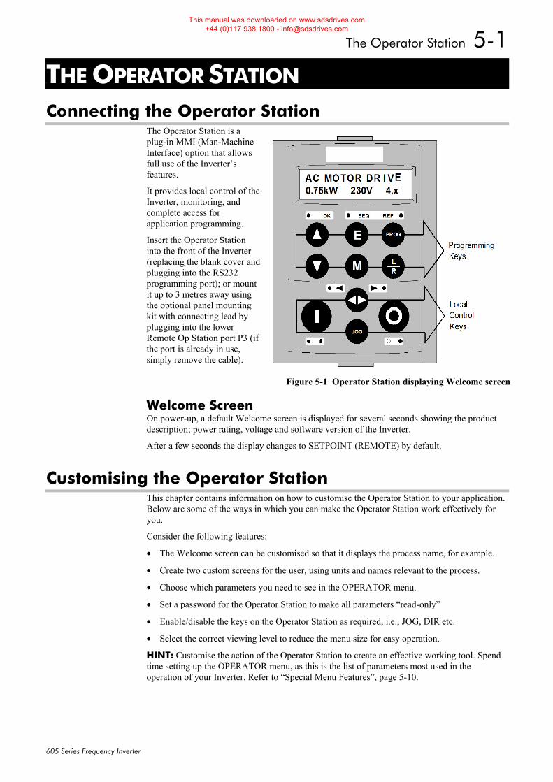
The Operator Station 5-1
605 Series Frequency Inverter
5THE OPERATOR STATION Connecting the Operator Station
The Operator Station is a plug-in MMI (Man-Machine Interface) option that allows full use of the Inverter’s features.
It provides local control of the Inverter, monitoring, and complete access for application programming.
Insert the Operator Station into the front of the Inverter (replacing the blank cover and plugging into the RS232 programming port); or mount it up to 3 metres away using the optional panel mounting kit with connecting lead by plugging into the lower Remote Op Station port P3 (if the port is already in use, simply remove the cable).
Welcome Screen On power-up, a default Welcome screen is displayed for several seconds showing the product description; power rating, voltage and software version of the Inverter.
After a few seconds the display changes to SETPOINT (REMOTE) by default.
Customising the Operator Station This chapter contains information on how to customise the Operator Station to your application. Below are some of the ways in which you can make the Operator Station work effectively for you.
Consider the following features:
• The Welcome screen can be customised so that it displays the process name, for example.
• Create two custom screens for the user, using units and names relevant to the process.
• Choose which parameters you need to see in the OPERATOR menu.
• Set a password for the Operator Station to make all parameters “read-only”
• Enable/disable the keys on the Operator Station as required, i.e., JOG, DIR etc.
• Select the correct viewing level to reduce the menu size for easy operation.
HINT: Customise the action of the Operator Station to create an effective working tool. Spend time setting up the OPERATOR menu, as this is the list of parameters most used in the operation of your Inverter. Refer to “Special Menu Features”, page 5-10.
Figure 5-1 Operator Station displaying Welcome screen
This manual was downloaded on www.sdsdrives.com +44 (0)117 938 1800 - [email protected]
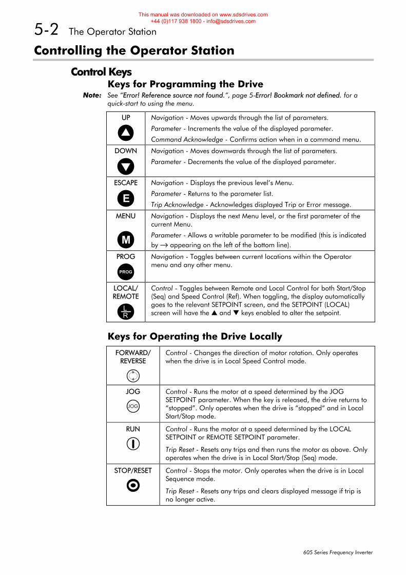
5-2 The Operator Station
605 Series Frequency Inverter
Controlling the Operator Station
Control Keys Keys for Programming the Drive
Note: See “Error! Reference source not found.”, page 5-Error! Bookmark not defined. for a quick-start to using the menu.
UP
Navigation - Moves upwards through the list of parameters.
Parameter - Increments the value of the displayed parameter.
Command Acknowledge - Confirms action when in a command menu.
DOWN
Navigation - Moves downwards through the list of parameters.
Parameter - Decrements the value of the displayed parameter.
ESCAPE
E
Navigation - Displays the previous level’s Menu.
Parameter - Returns to the parameter list.
Trip Acknowledge - Acknowledges displayed Trip or Error message.
MENU
M
Navigation - Displays the next Menu level, or the first parameter of the current Menu.
Parameter - Allows a writable parameter to be modified (this is indicated by → appearing on the left of the bottom line).
PROG
PROG
Navigation - Toggles between current locations within the Operator menu and any other menu.
LOCAL/ REMOTE
RL
Control - Toggles between Remote and Local Control for both Start/Stop (Seq) and Speed Control (Ref). When toggling, the display automatically goes to the relevant SETPOINT screen, and the SETPOINT (LOCAL) screen will have the and keys enabled to alter the setpoint.
Keys for Operating the Drive Locally
FORWARD/ REVERSE
Control - Changes the direction of motor rotation. Only operates when the drive is in Local Speed Control mode.
JOG
JOG
Control - Runs the motor at a speed determined by the JOG SETPOINT parameter. When the key is released, the drive returns to “stopped”. Only operates when the drive is “stopped“ and in Local Start/Stop mode.
RUN
Control - Runs the motor at a speed determined by the LOCAL SETPOINT or REMOTE SETPOINT parameter.
Trip Reset - Resets any trips and then runs the motor as above. Only operates when the drive is in Local Start/Stop (Seq) mode.
STOP/RESET
Control - Stops the motor. Only operates when the drive is in Local Sequence mode.
Trip Reset - Resets any trips and clears displayed message if trip is no longer active.
This manual was downloaded on www.sdsdrives.com +44 (0)117 938 1800 - [email protected]
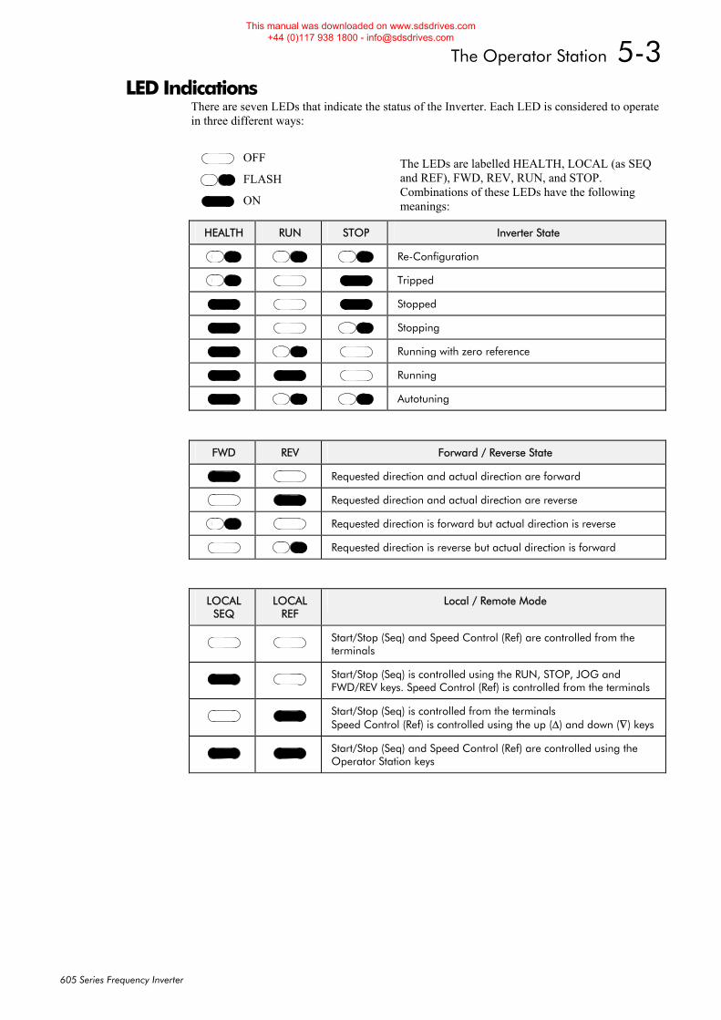
The Operator Station 5-3
605 Series Frequency Inverter
LED Indications There are seven LEDs that indicate the status of the Inverter. Each LED is considered to operate in three different ways:
The LEDs are labelled HEALTH, LOCAL (as SEQ and REF), FWD, REV, RUN, and STOP. Combinations of these LEDs have the following meanings:
HEALTH RUN STOP Inverter State
Re-Configuration
Tripped
Stopped
Stopping
Running with zero reference
Running
Autotuning
FWD REV Forward / Reverse State
Requested direction and actual direction are forward
Requested direction and actual direction are reverse
Requested direction is forward but actual direction is reverse
Requested direction is reverse but actual direction is forward
LOCAL
SEQ LOCAL
REF Local / Remote Mode
Start/Stop (Seq) and Speed Control (Ref) are controlled from the terminals
Start/Stop (Seq) is controlled using the RUN, STOP, JOG and FWD/REV keys. Speed Control (Ref) is controlled from the terminals
Start/Stop (Seq) is controlled from the terminals Speed Control (Ref) is controlled using the up (Δ) and down (∇) keys
Start/Stop (Seq) and Speed Control (Ref) are controlled using the Operator Station keys
OFF
FLASH
ON
This manual was downloaded on www.sdsdrives.com +44 (0)117 938 1800 - [email protected]
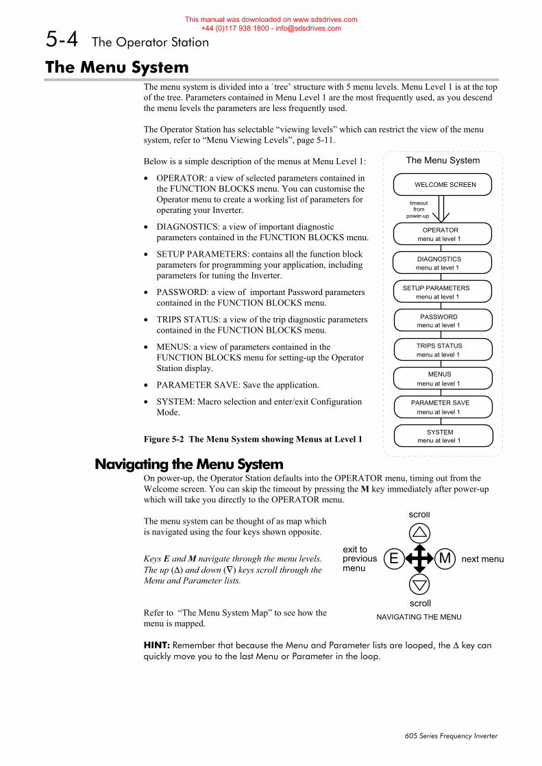
5-4 The Operator Station
605 Series Frequency Inverter
The Menu System The menu system is divided into a `tree’ structure with 5 menu levels. Menu Level 1 is at the top of the tree. Parameters contained in Menu Level 1 are the most frequently used, as you descend the menu levels the parameters are less frequently used. The Operator Station has selectable “viewing levels” which can restrict the view of the menu system, refer to “Menu Viewing Levels”, page 5-11. Below is a simple description of the menus at Menu Level 1:
• OPERATOR: a view of selected parameters contained in the FUNCTION BLOCKS menu. You can customise the Operator menu to create a working list of parameters for operating your Inverter.
• DIAGNOSTICS: a view of important diagnostic parameters contained in the FUNCTION BLOCKS menu.
• SETUP PARAMETERS: contains all the function block parameters for programming your application, including parameters for tuning the Inverter.
• PASSWORD: a view of important Password parameters contained in the FUNCTION BLOCKS menu.
• TRIPS STATUS: a view of the trip diagnostic parameters contained in the FUNCTION BLOCKS menu.
• MENUS: a view of parameters contained in the FUNCTION BLOCKS menu for setting-up the Operator Station display.
• PARAMETER SAVE: Save the application.
• SYSTEM: Macro selection and enter/exit Configuration Mode.
Figure 5-2 The Menu System showing Menus at Level 1
Navigating the Menu System On power-up, the Operator Station defaults into the OPERATOR menu, timing out from the Welcome screen. You can skip the timeout by pressing the M key immediately after power-up which will take you directly to the OPERATOR menu.
The menu system can be thought of as map which is navigated using the four keys shown opposite.
Keys E and M navigate through the menu levels. The up (Δ) and down (∇) keys scroll through the Menu and Parameter lists.
Refer to “The Menu System Map” to see how the menu is mapped. HINT: Remember that because the Menu and Parameter lists are looped, the Δ key can quickly move you to the last Menu or Parameter in the loop.
WELCOME SCREEN
OPERATOR
The Menu System
timeoutfrom
power-up
DIAGNOSTICS
SETUP PARAMETERS
PASSWORD
TRIPS STATUS
MENUS
PARAMETER SAVE
SYSTEM
menu at level 1
menu at level 1
menu at level 1
menu at level 1
menu at level 1
menu at level 1
menu at level 1
menu at level 1
scroll
scroll
exit topreviousmenu
next menu
NAVIGATING THE MENU
E M
This manual was downloaded on www.sdsdrives.com +44 (0)117 938 1800 - [email protected]
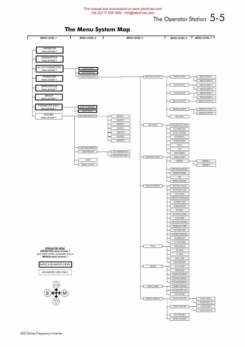
The Operator Station 5-5
605 Series Frequency Inverter
The Menu System Map MENU LEVEL 2
INPUTS & OUTPUTS
SEQ & REF
SETPOINT FUNCS
MOTOR CONTROL
TRIPS
MENUS
SERIAL LINKS
ANALOG INPUT 1
ANALOG INPUT 2
ENCODER
DIGITAL INPUT 1
DIGITAL INPUT 5
ANALOG DIGIN 1
ANALOG DIGIN 2
ANALOG OUTPUT 1
DIGITAL OUTPUT 1
DIGITAL OUTPUT 2
PRESET 1
PRESET 8
VALUE FUNC 1
VALUE FUNC 10
LOGIC FUNC 1
LOGIC FUNC 10
ANALOG INPUT
DIGITAL INPUT
ANALOG DIGIN
ANALOG OUTPUT
DIGITAL OUTPUT
SEQUENCING LOGIC
AUTO RESTART
LOCAL CONTROL
REFERENCE
SYSTEM RAMP
STOP
JOG
ZERO SPEED
RAISE/LOWER
PRESET
SKIP FREQUENCIES
MINIMUM SPEED
PID
BRAKE CONTROL
MISCELLANEOUS
MULTIPLEXER
DEMULTIPLEXER
SETPOINT SCALE
SLEW RATE LIMIT
SLIP COMP
CURRENT FEEDBACK
CURRENT LIMIT
STABILISATION
FLUXING
VECTOR FLUXING
AUTOTUNE
VOLTAGE CONTROL
UNDERLAP COMP
PATTERN GEN
DYNAMIC BRAKING
INJ BRAKING
FLY CATCHING
TRIPS STATUS
I/O TRIPS
I*T TRIPS
STALL TRIP
TRIPS HISTORY
OP STATION
PASSWORD
OPERATOR MENU
CUSTOM SCREEN 1
CUSTOM SCREEN 2
COMMS CONTROL
SYSTEM PORT (P3)
ALL PARAMETERS
APPLICATION ONLY
E M
ADVANCED VIEW ONLY
MENU LEVEL 3 MENU LEVEL 4 MENU LEVEL 5MENU LEVEL 1
QUICK SETUP
VECTOR SETUP
SETUP PARAMETERSmenu at level 1
PASSWORDmenu at level 1
MACRO 1
MACRO 2
MACRO 3
MACRO 4
ENABLE CONFIG
RESTORE DEFAULTS
LOAD FROM MEMORY
LOAD FROM OP
LINKS
SAVE TO MEMORY
SAVE TO OP
TRIPS STATUSmenu at level 1
MENUSmenu at level 1
SYSTEMmenu at level 1
PARAMETER SAVEmenu at level 1
DIAGNOSTICSmenu at level 1
FUNCTION BLOCKS
BASIC & ADVANCED VIEWS
OPERATOR VIEW:OPERATOR menu at level 1
plus VIEW LEVEL parameter only inMENUS menu at level 1
MACRO 5
VALUE FUNCTION
LOGIC FUNCTION
TEC OPTION
OPERATORmenu at level 1
MACRO 6
MACRO 0
This manual was downloaded on www.sdsdrives.com +44 (0)117 938 1800 - [email protected]
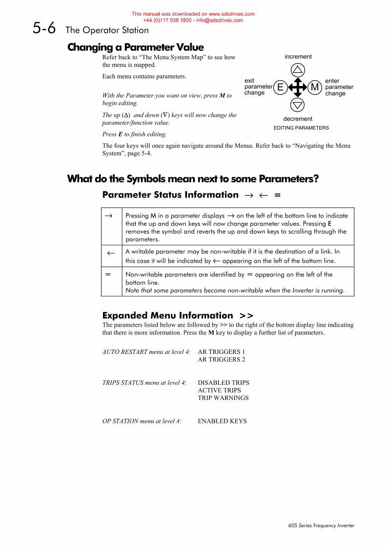
5-6 The Operator Station
605 Series Frequency Inverter
Changing a Parameter Value Refer back to “The Menu System Map” to see how the menu is mapped.
Each menu contains parameters.
With the Parameter you want on view, press M to begin editing.
The up (Δ) and down (∇) keys will now change the parameter/function value.
Press E to finish editing.
The four keys will once again navigate around the Menus. Refer back to “Navigating the Menu System”, page 5-4.
What do the Symbols mean next to some Parameters? Parameter Status Information → ← =
→ Pressing M in a parameter displays → on the left of the bottom line to indicate that the up and down keys will now change parameter values. Pressing E removes the symbol and reverts the up and down keys to scrolling through the parameters.
← A writable parameter may be non-writable if it is the destination of a link. In this case it will be indicated by ← appearing on the left of the bottom line.
= Non-writable parameters are identified by = appearing on the left of the bottom line. Note that some parameters become non-writable when the Inverter is running.
Expanded Menu Information >> The parameters listed below are followed by >> to the right of the bottom display line indicating that there is more information. Press the M key to display a further list of parameters.
AUTO RESTART menu at level 4: AR TRIGGERS 1 AR TRIGGERS 2
TRIPS STATUS menu at level 4: DISABLED TRIPS ACTIVE TRIPS TRIP WARNINGS
OP STATION menu at level 4: ENABLED KEYS
increment
decrement
parameterchange
exitparameterchange
EDITING PARAMETERS
E Menter
This manual was downloaded on www.sdsdrives.com +44 (0)117 938 1800 - [email protected]
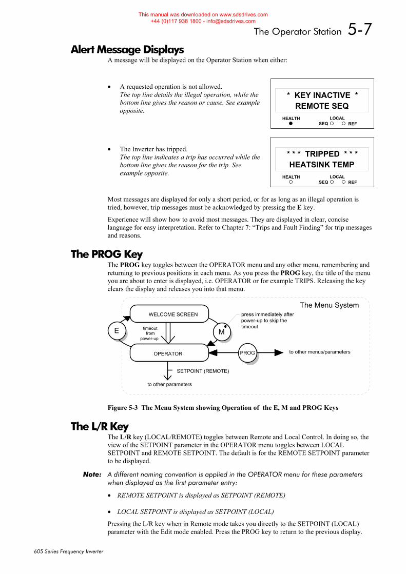
The Operator Station 5-7
605 Series Frequency Inverter
Alert Message Displays A message will be displayed on the Operator Station when either:
• A requested operation is not allowed. The top line details the illegal operation, while the bottom line gives the reason or cause. See example opposite.
• The Inverter has tripped.
The top line indicates a trip has occurred while the bottom line gives the reason for the trip. See example opposite.
Most messages are displayed for only a short period, or for as long as an illegal operation is tried, however, trip messages must be acknowledged by pressing the E key.
Experience will show how to avoid most messages. They are displayed in clear, concise language for easy interpretation. Refer to Chapter 7: “Trips and Fault Finding” for trip messages and reasons.
The PROG Key The PROG key toggles between the OPERATOR menu and any other menu, remembering and returning to previous positions in each menu. As you press the PROG key, the title of the menu you are about to enter is displayed, i.e. OPERATOR or for example TRIPS. Releasing the key clears the display and releases you into that menu.
WELCOME SCREEN
OPERATOR PROG
The Menu System
ME
SETPOINT (REMOTE)
to other parameters
to other menus/parameters
press immediately afterpower-up to skip thetimeouttimeout
frompower-up
Figure 5-3 The Menu System showing Operation of the E, M and PROG Keys
The L/R Key The L/R key (LOCAL/REMOTE) toggles between Remote and Local Control. In doing so, the view of the SETPOINT parameter in the OPERATOR menu toggles between LOCAL SETPOINT and REMOTE SETPOINT. The default is for the REMOTE SETPOINT parameter to be displayed.
Note: A different naming convention is applied in the OPERATOR menu for these parameters when displayed as the first parameter entry:
• REMOTE SETPOINT is displayed as SETPOINT (REMOTE) • LOCAL SETPOINT is displayed as SETPOINT (LOCAL)
Pressing the L/R key when in Remote mode takes you directly to the SETPOINT (LOCAL) parameter with the Edit mode enabled. Press the PROG key to return to the previous display.
HEALTH LOCALSEQ REF
11REMOTE SEQ
* KEY INACTIVE *
HEALTH LOCALSEQ REF
11HEATSINK TEMP
* * * TRIPPED * * *
This manual was downloaded on www.sdsdrives.com +44 (0)117 938 1800 - [email protected]
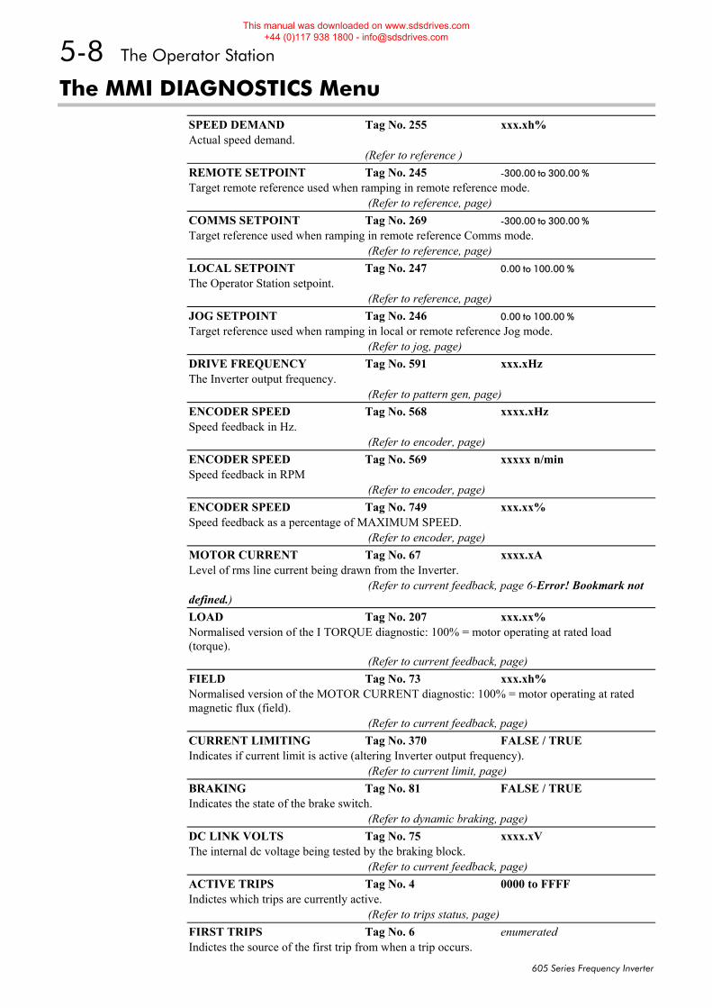
5-8 The Operator Station
605 Series Frequency Inverter
The MMI DIAGNOSTICS Menu
SPEED DEMAND Tag No. 255 xxx.xh% Actual speed demand. (Refer to reference ) REMOTE SETPOINT Tag No. 245 -300.00 to 300.00 % Target remote reference used when ramping in remote reference mode. (Refer to reference, page) COMMS SETPOINT Tag No. 269 -300.00 to 300.00 % Target reference used when ramping in remote reference Comms mode. (Refer to reference, page) LOCAL SETPOINT Tag No. 247 0.00 to 100.00 % The Operator Station setpoint. (Refer to reference, page) JOG SETPOINT Tag No. 246 0.00 to 100.00 % Target reference used when ramping in local or remote reference Jog mode. (Refer to jog, page) DRIVE FREQUENCY Tag No. 591 xxx.xHz The Inverter output frequency. (Refer to pattern gen, page) ENCODER SPEED Tag No. 568 xxxx.xHz Speed feedback in Hz. (Refer to encoder, page) ENCODER SPEED Tag No. 569 xxxxx n/min Speed feedback in RPM (Refer to encoder, page) ENCODER SPEED Tag No. 749 xxx.xx% Speed feedback as a percentage of MAXIMUM SPEED. (Refer to encoder, page) MOTOR CURRENT Tag No. 67 xxxx.xA Level of rms line current being drawn from the Inverter. (Refer to current feedback, page 6-Error! Bookmark not defined.) LOAD Tag No. 207 xxx.xx% Normalised version of the I TORQUE diagnostic: 100% = motor operating at rated load (torque). (Refer to current feedback, page) FIELD Tag No. 73 xxx.xh% Normalised version of the MOTOR CURRENT diagnostic: 100% = motor operating at rated magnetic flux (field). (Refer to current feedback, page) CURRENT LIMITING Tag No. 370 FALSE / TRUE Indicates if current limit is active (altering Inverter output frequency). (Refer to current limit, page) BRAKING Tag No. 81 FALSE / TRUE Indicates the state of the brake switch. (Refer to dynamic braking, page) DC LINK VOLTS Tag No. 75 xxxx.xV The internal dc voltage being tested by the braking block. (Refer to current feedback, page) ACTIVE TRIPS Tag No. 4 0000 to FFFF Indictes which trips are currently active. (Refer to trips status, page) FIRST TRIPS Tag No. 6 enumerated Indictes the source of the first trip from when a trip occurs.
This manual was downloaded on www.sdsdrives.com +44 (0)117 938 1800 - [email protected]
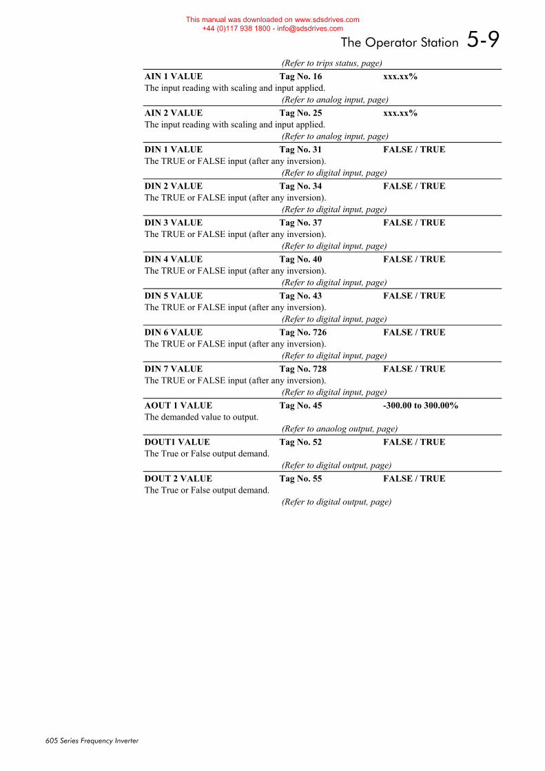
The Operator Station 5-9
605 Series Frequency Inverter
(Refer to trips status, page) AIN 1 VALUE Tag No. 16 xxx.xx% The input reading with scaling and input applied. (Refer to analog input, page) AIN 2 VALUE Tag No. 25 xxx.xx% The input reading with scaling and input applied. (Refer to analog input, page) DIN 1 VALUE Tag No. 31 FALSE / TRUE The TRUE or FALSE input (after any inversion). (Refer to digital input, page) DIN 2 VALUE Tag No. 34 FALSE / TRUE The TRUE or FALSE input (after any inversion). (Refer to digital input, page) DIN 3 VALUE Tag No. 37 FALSE / TRUE The TRUE or FALSE input (after any inversion). (Refer to digital input, page) DIN 4 VALUE Tag No. 40 FALSE / TRUE The TRUE or FALSE input (after any inversion). (Refer to digital input, page) DIN 5 VALUE Tag No. 43 FALSE / TRUE The TRUE or FALSE input (after any inversion). (Refer to digital input, page) DIN 6 VALUE Tag No. 726 FALSE / TRUE The TRUE or FALSE input (after any inversion). (Refer to digital input, page) DIN 7 VALUE Tag No. 728 FALSE / TRUE The TRUE or FALSE input (after any inversion). (Refer to digital input, page) AOUT 1 VALUE Tag No. 45 -300.00 to 300.00% The demanded value to output. (Refer to anaolog output, page) DOUT1 VALUE Tag No. 52 FALSE / TRUE The True or False output demand. (Refer to digital output, page) DOUT 2 VALUE Tag No. 55 FALSE / TRUE The True or False output demand. (Refer to digital output, page)
This manual was downloaded on www.sdsdrives.com +44 (0)117 938 1800 - [email protected]
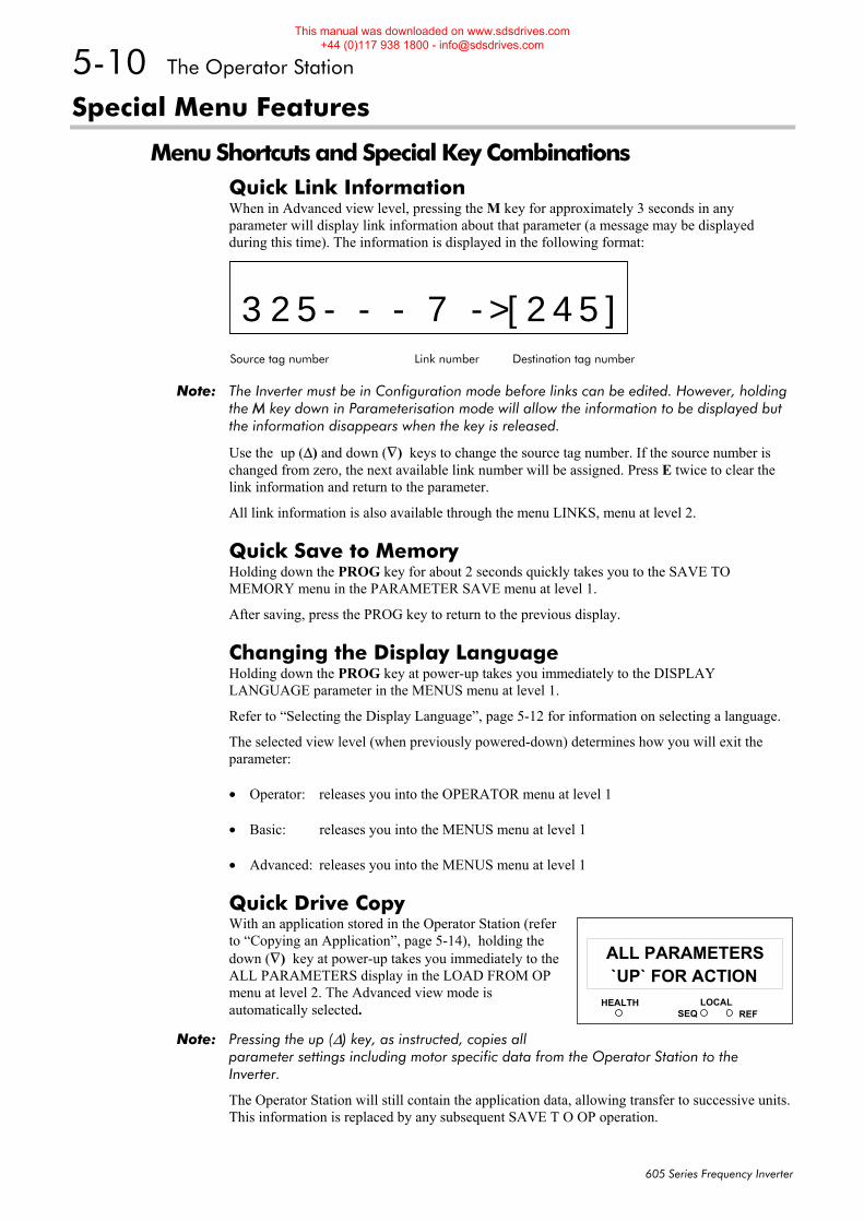
5-10 The Operator Station
605 Series Frequency Inverter
Special Menu Features
Menu Shortcuts and Special Key Combinations Quick Link Information When in Advanced view level, pressing the M key for approximately 3 seconds in any parameter will display link information about that parameter (a message may be displayed during this time). The information is displayed in the following format:
325- - - 7 ->[245]Source tag number Link number Destination tag number
Note: The Inverter must be in Configuration mode before links can be edited. However, holding the M key down in Parameterisation mode will allow the information to be displayed but the information disappears when the key is released.
Use the up (Δ) and down (∇) keys to change the source tag number. If the source number is changed from zero, the next available link number will be assigned. Press E twice to clear the link information and return to the parameter.
All link information is also available through the menu LINKS, menu at level 2.
Quick Save to Memory Holding down the PROG key for about 2 seconds quickly takes you to the SAVE TO MEMORY menu in the PARAMETER SAVE menu at level 1.
After saving, press the PROG key to return to the previous display.
Changing the Display Language Holding down the PROG key at power-up takes you immediately to the DISPLAY LANGUAGE parameter in the MENUS menu at level 1.
Refer to “Selecting the Display Language”, page 5-12 for information on selecting a language.
The selected view level (when previously powered-down) determines how you will exit the parameter:
• Operator: releases you into the OPERATOR menu at level 1
• Basic: releases you into the MENUS menu at level 1
• Advanced: releases you into the MENUS menu at level 1
Quick Drive Copy With an application stored in the Operator Station (refer to “Copying an Application”, page 5-14), holding the down (∇) key at power-up takes you immediately to the ALL PARAMETERS display in the LOAD FROM OP menu at level 2. The Advanced view mode is automatically selected.
Note: Pressing the up (Δ) key, as instructed, copies all parameter settings including motor specific data from the Operator Station to the Inverter.
The Operator Station will still contain the application data, allowing transfer to successive units. This information is replaced by any subsequent SAVE T O OP operation.
HEALTH LOCALSEQ REF
11`UP` FOR ACTION
ALL PARAMETERS
This manual was downloaded on www.sdsdrives.com +44 (0)117 938 1800 - [email protected]
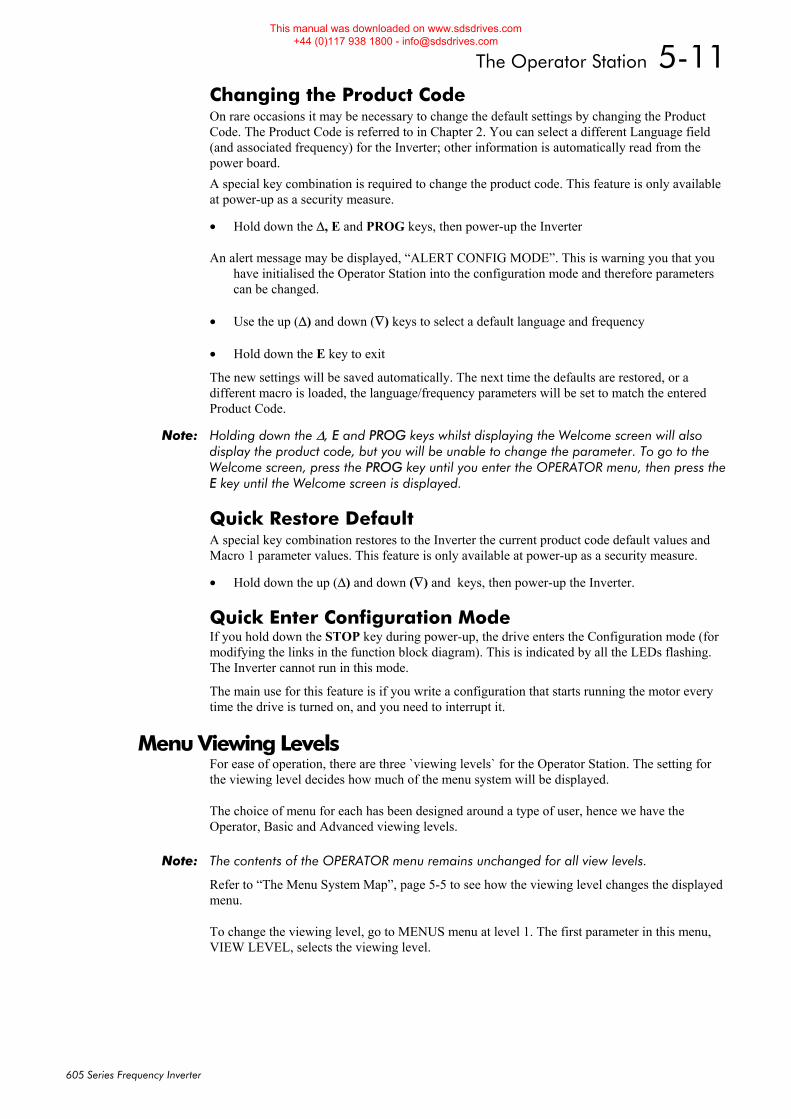
The Operator Station 5-11
605 Series Frequency Inverter
Changing the Product Code On rare occasions it may be necessary to change the default settings by changing the Product Code. The Product Code is referred to in Chapter 2. You can select a different Language field (and associated frequency) for the Inverter; other information is automatically read from the power board. A special key combination is required to change the product code. This feature is only available at power-up as a security measure.
• Hold down the Δ, E and PROG keys, then power-up the Inverter
An alert message may be displayed, “ALERT CONFIG MODE”. This is warning you that you have initialised the Operator Station into the configuration mode and therefore parameters can be changed.
• Use the up (Δ) and down (∇) keys to select a default language and frequency
• Hold down the E key to exit
The new settings will be saved automatically. The next time the defaults are restored, or a different macro is loaded, the language/frequency parameters will be set to match the entered Product Code.
Note: Holding down the Δ, E and PROG keys whilst displaying the Welcome screen will also display the product code, but you will be unable to change the parameter. To go to the Welcome screen, press the PROG key until you enter the OPERATOR menu, then press the E key until the Welcome screen is displayed.
Quick Restore Default A special key combination restores to the Inverter the current product code default values and Macro 1 parameter values. This feature is only available at power-up as a security measure.
• Hold down the up (Δ) and down (∇) and keys, then power-up the Inverter.
Quick Enter Configuration Mode If you hold down the STOP key during power-up, the drive enters the Configuration mode (for modifying the links in the function block diagram). This is indicated by all the LEDs flashing. The Inverter cannot run in this mode.
The main use for this feature is if you write a configuration that starts running the motor every time the drive is turned on, and you need to interrupt it.
Menu Viewing Levels For ease of operation, there are three `viewing levels` for the Operator Station. The setting for the viewing level decides how much of the menu system will be displayed.
The choice of menu for each has been designed around a type of user, hence we have the Operator, Basic and Advanced viewing levels.
Note: The contents of the OPERATOR menu remains unchanged for all view levels.
Refer to “The Menu System Map”, page 5-5 to see how the viewing level changes the displayed menu.
To change the viewing level, go to MENUS menu at level 1. The first parameter in this menu, VIEW LEVEL, selects the viewing level.
This manual was downloaded on www.sdsdrives.com +44 (0)117 938 1800 - [email protected]
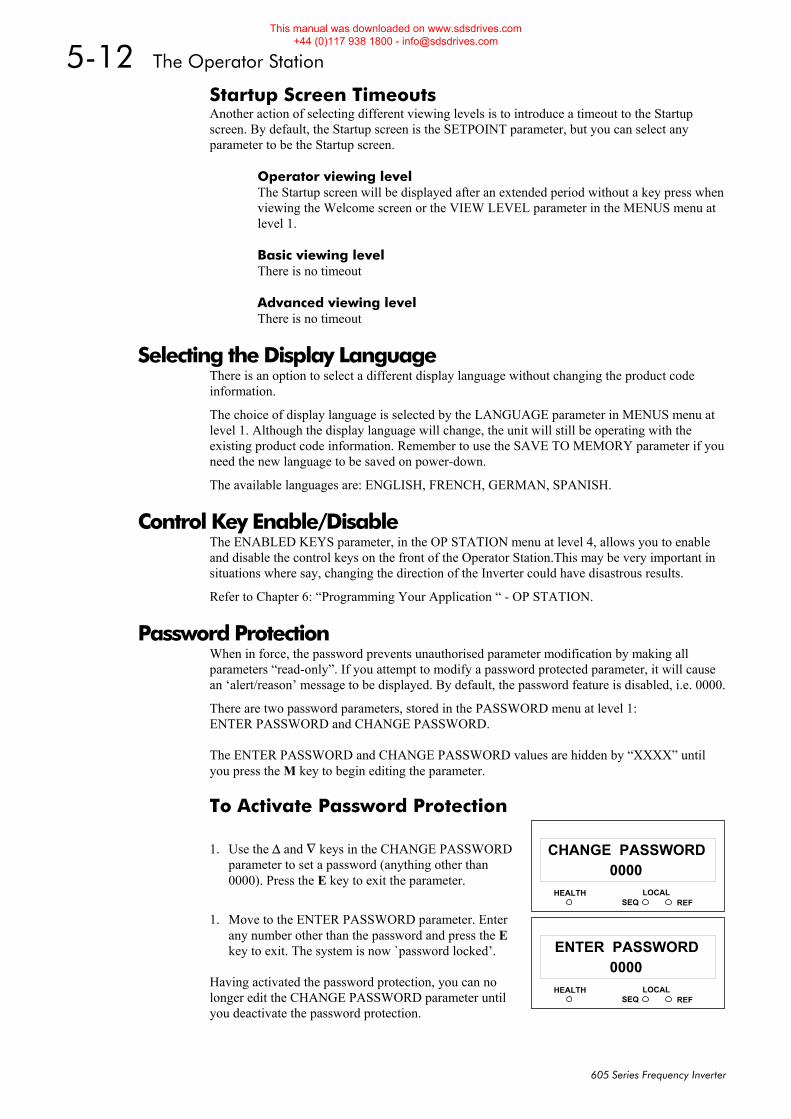
5-12 The Operator Station
605 Series Frequency Inverter
Startup Screen Timeouts Another action of selecting different viewing levels is to introduce a timeout to the Startup screen. By default, the Startup screen is the SETPOINT parameter, but you can select any parameter to be the Startup screen.
Operator viewing level The Startup screen will be displayed after an extended period without a key press when viewing the Welcome screen or the VIEW LEVEL parameter in the MENUS menu at level 1.
Basic viewing level There is no timeout
Advanced viewing level There is no timeout
Selecting the Display Language There is an option to select a different display language without changing the product code information.
The choice of display language is selected by the LANGUAGE parameter in MENUS menu at level 1. Although the display language will change, the unit will still be operating with the existing product code information. Remember to use the SAVE TO MEMORY parameter if you need the new language to be saved on power-down.
The available languages are: ENGLISH, FRENCH, GERMAN, SPANISH.
Control Key Enable/Disable The ENABLED KEYS parameter, in the OP STATION menu at level 4, allows you to enable and disable the control keys on the front of the Operator Station.This may be very important in situations where say, changing the direction of the Inverter could have disastrous results.
Refer to Chapter 6: “Programming Your Application “ - OP STATION.
Password Protection When in force, the password prevents unauthorised parameter modification by making all parameters “read-only”. If you attempt to modify a password protected parameter, it will cause an ‘alert/reason’ message to be displayed. By default, the password feature is disabled, i.e. 0000.
There are two password parameters, stored in the PASSWORD menu at level 1: ENTER PASSWORD and CHANGE PASSWORD. The ENTER PASSWORD and CHANGE PASSWORD values are hidden by “XXXX” until you press the M key to begin editing the parameter.
To Activate Password Protection
1. Use the Δ and ∇ keys in the CHANGE PASSWORD parameter to set a password (anything other than 0000). Press the E key to exit the parameter.
1. Move to the ENTER PASSWORD parameter. Enter any number other than the password and press the E key to exit. The system is now `password locked’.
Having activated the password protection, you can no longer edit the CHANGE PASSWORD parameter until you deactivate the password protection.
HEALTH LOCALSEQ REF
110000
CHANGE PASSWORD
HEALTH LOCALSEQ REF
110000
ENTER PASSWORD
This manual was downloaded on www.sdsdrives.com +44 (0)117 938 1800 - [email protected]
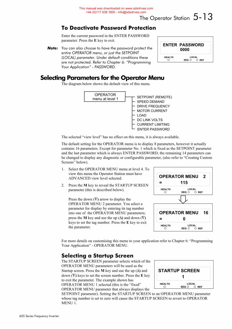
The Operator Station 5-13
605 Series Frequency Inverter
To Deactivate Password Protection Enter the current password in the ENTER PASSWORD parameter. Press the E key to exit.
Note: You can also choose to have the password protect the entire OPERATOR menu, or just the SETPOINT (LOCAL) parameter. Under default conditions these are not protected. Refer to Chapter 6: “Programming Your Application” - PASSWORD.
Selecting Parameters for the Operator Menu The diagram below shows the default view of this menu.
The selected “view level” has no effect on this menu, it is always available.
The default setting for the OPERATOR menu is to display 8 parameters, however it actually contains 16 parameters. Except for parameter No. 1 which is fixed as the SETPOINT parameter and the last parameter which is always ENTER PASSWORD, the remaining 14 parameters can be changed to display any diagnostic or configurable parameter, (also refer to “Creating Custom Screens” below).
1. Select the OPERATOR MENU menu at level 4. To view this menu the Operator Station must have ADVANCED view level selected.
2. Press the M key to reveal the STARTUP SCREEN parameter (this is described below). Press the down (∇) arrow to display the OPERATOR MENU 2 parameter. You select a parameter for display by entering its tag number into one of the OPERATOR MENU parameters; press the M key and use the up (Δ) and down (∇) keys to set the tag number. Press the E key to exit the parameter.
For more details on customising this menu to your application refer to Chapter 6: “Programming Your Application” - OPERATOR MENU.
Selecting a Startup Screen The STARTUP SCREEN parameter selects which of the OPERATOR MENU parameters will be used as the Startup screen. Press the M key and use the up (Δ) and down (∇) keys to set the screen number. Press the E key to exit the parameter. The example shown has OPERATOR MENU 1 selected (this is the “fixed” OPERATOR MENU parameter that always displays the SETPOINT parameter). Setting the STARTUP SCREEN to an OPERATOR MENU parameter whose tag number is set to zero will cause the STARTUP SCREEN to revert to OPERATOR MENU 1.
HEALTH LOCALSEQ REF
110000
ENTER PASSWORD
SETPOINT (REMOTE)SPEED DEMANDDRIVE FREQUENCYMOTOR CURRENTLOADDC LINK VOLTSCURRENT LIMITINGENTER PASSWORD
OPERATORmenu at level 1
HEALTH LOCALSEQ REF
11= 115
OPERATOR MENU 2
HEALTH LOCALSEQ REF
11= 0
OPERATOR MENU 16
HEALTH LOCALSEQ REF
11 1
STARTUP SCREEN
This manual was downloaded on www.sdsdrives.com +44 (0)117 938 1800 - [email protected]
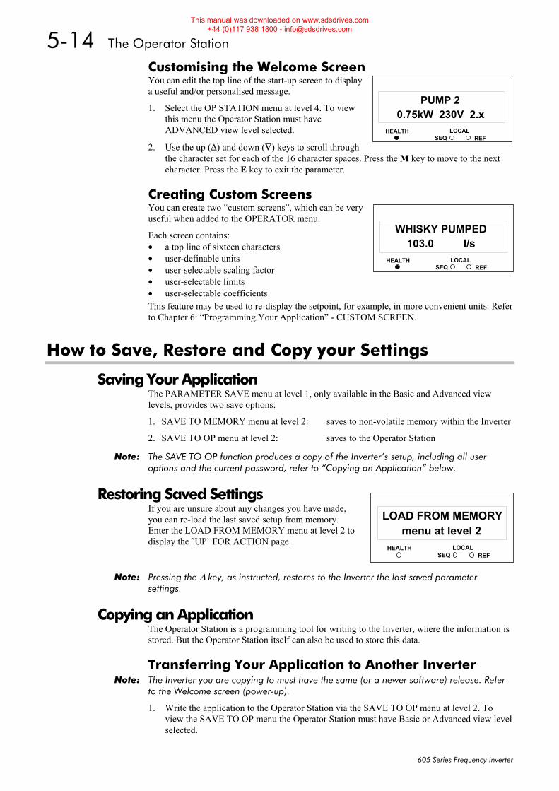
5-14 The Operator Station
605 Series Frequency Inverter
Customising the Welcome Screen You can edit the top line of the start-up screen to display a useful and/or personalised message.
1. Select the OP STATION menu at level 4. To view this menu the Operator Station must have ADVANCED view level selected.
2. Use the up (Δ) and down (∇) keys to scroll through the character set for each of the 16 character spaces. Press the M key to move to the next character. Press the E key to exit the parameter.
Creating Custom Screens You can create two “custom screens”, which can be very useful when added to the OPERATOR menu.
Each screen contains: • a top line of sixteen characters • user-definable units • user-selectable scaling factor • user-selectable limits • user-selectable coefficients This feature may be used to re-display the setpoint, for example, in more convenient units. Refer to Chapter 6: “Programming Your Application” - CUSTOM SCREEN.
How to Save, Restore and Copy your Settings
Saving Your Application The PARAMETER SAVE menu at level 1, only available in the Basic and Advanced view levels, provides two save options:
1. SAVE TO MEMORY menu at level 2: saves to non-volatile memory within the Inverter
2. SAVE TO OP menu at level 2: saves to the Operator Station
Note: The SAVE TO OP function produces a copy of the Inverter’s setup, including all user options and the current password, refer to “Copying an Application” below.
Restoring Saved Settings If you are unsure about any changes you have made, you can re-load the last saved setup from memory. Enter the LOAD FROM MEMORY menu at level 2 to display the `UP` FOR ACTION page.
Note: Pressing the Δ key, as instructed, restores to the Inverter the last saved parameter settings.
Copying an Application The Operator Station is a programming tool for writing to the Inverter, where the information is stored. But the Operator Station itself can also be used to store this data.
Transferring Your Application to Another Inverter Note: The Inverter you are copying to must have the same (or a newer software) release. Refer
to the Welcome screen (power-up).
1. Write the application to the Operator Station via the SAVE TO OP menu at level 2. To view the SAVE TO OP menu the Operator Station must have Basic or Advanced view level selected.
HEALTH LOCALSEQ REF
110.75kW 230V 2.x
PUMP 2
HEALTH LOCALSEQ REF
11103.0 l/s
WHISKY PUMPED
HEALTH LOCALSEQ REF
11menu at level 2
LOAD FROM MEMORY
This manual was downloaded on www.sdsdrives.com +44 (0)117 938 1800 - [email protected]

The Operator Station 5-15
605 Series Frequency Inverter
2. Connect the Operator Station to the receiving Inverter.
3. Select Advanced view level, if necessary. Transfer the data via the LOAD FROM OP menu at level 2. Two sub-menus allow you to choose between loading a full parameter load which includes motor-specific data, or just the application without any motor-specific data:
ALL PARAMETERS APPLICATION ONLY
Refer to Chapter 6: “Programming Your Application” - Motor-Specific Parameters.
Note: Both methods will transfer the password of the host unit. Refer to “Password Protection” , page 5-12.
The Operator Station still has the application data stored allowing transfer to successive units. This information is replaced by any subsequent SAVE TO OP operation.
Backing-up Your Application The Operator Station can be used to back-up the application data stored in the Inverter as a safety measure. Refer to “Transferring Your Application to Another Inverter” above.
You can have the Operator Station back-up the application each time a SAVE TO MEMORY is performed by enabling the AUTO BACKUP parameter. Refer to Chapter 6: “Programming Your Application” - OP STATION.
This manual was downloaded on www.sdsdrives.com +44 (0)117 938 1800 - [email protected]

5-16 The Operator Station
605 Series Frequency Inverter
This manual was downloaded on www.sdsdrives.com +44 (0)117 938 1800 - [email protected]
Programming Your Application 6-1
605 Series Frequency Inverter
6PROGRAMMING YOUR APPLICATION Introducing the Macro
You can program the Inverter for specific applications.
The Inverter is supplied with macros (set-ups) which can be used as starting points for application-specific programming. This programming could simply involve the inputting of parameter values, or it may require the making or breaking of programmable links, which is a feature of this unit.
Each macro instantly recalls a pre-programmed set of default parameters when it is loaded.
Refer to Chapter 15: “Application Macros” for further information.
Programming with Block Diagrams Block diagram programming provides a visual method of planning the software to suit your application. There are ten block diagrams provided at the end of this chapter, each showing the software connections for an application macro.
The processes performed by a macro are represented as a block diagram, consisting of function blocks and links:
• Each function block contains the parameters required for setting-up a particular processing feature. Sometimes more than one function block is provided for a feature, i.e. for multiple digital inputs.
• Software links are used to connect the function blocks. Each link transfers the value of an output parameter to an input parameter of another (or the same) function block.
Each individual block is a processing feature, i.e. it takes the input parameter, processes the information, and makes the result available as one or more output parameters.
Modifying a Block Diagram Configuration and Parameterisation Modes There are two modes of operation used while modifying a block diagram: Parameterisation and Configuration modes.
The ENABLE CONFIG and DISABLE CONFIG commands, found under SYSTEM menu at level 1, is used to toggle between these two modes of operation.
Parameterisation Mode In parameterisation mode you can change parameter values. The Inverter can be running or stopped. Note that some parameters can only be changed when the Inverter is stopped. It is not possible to modify the internal links when the Inverter is in parameterisation mode.
Configuration Mode In the configuration mode you can modify the links in the function block diagram. You can also change parameter values, as above. This mode is indicated by all the LEDs on the operator station flashing at once. The Inverter cannot run in this mode.
Making and Breaking Links in Configuration Mode Links can be moved, added or deleted from a block diagram whilst in the Configuration mode. There are 50 links available, each has its own identification number (“link” number). You make a link by setting the link’s “source” and “destination” tags to be the two parameter tag numbers to be linked. The outputs of function blocks are not updated whilst in this mode.
DEFAULT
This manual was downloaded on www.sdsdrives.com +44 (0)117 938 1800 - [email protected]
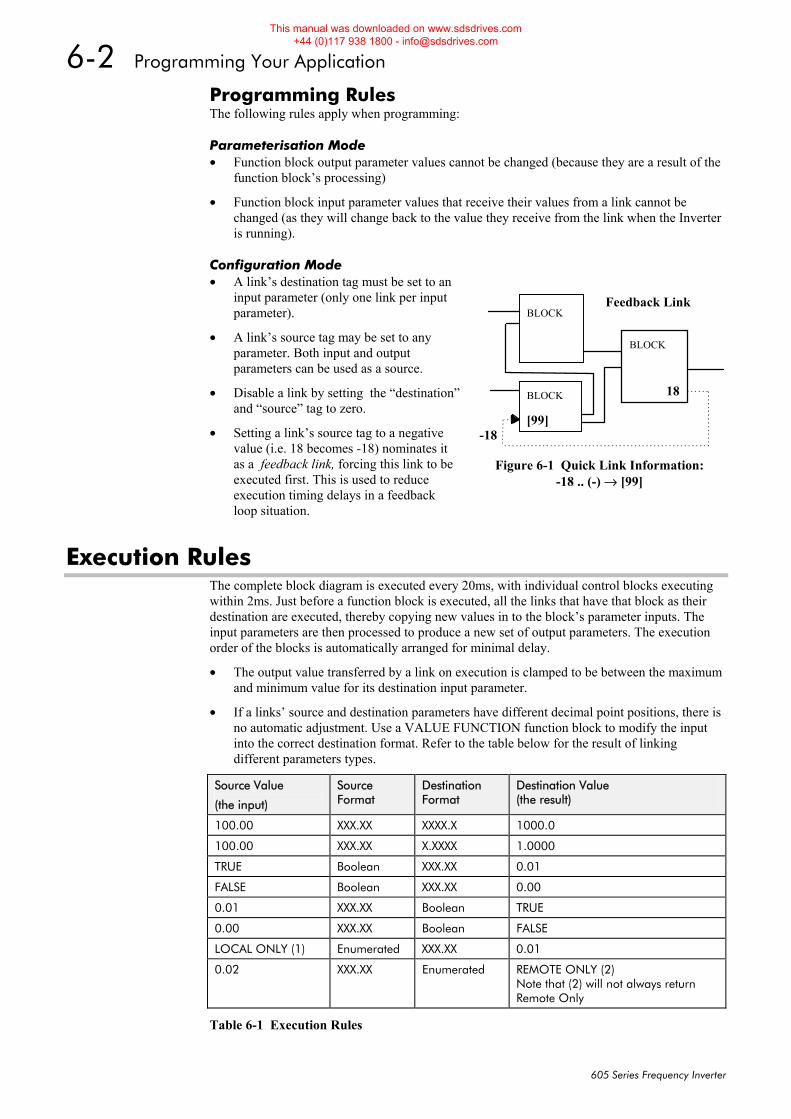
6-2 Programming Your Application
605 Series Frequency Inverter
Programming Rules The following rules apply when programming:
Parameterisation Mode • Function block output parameter values cannot be changed (because they are a result of the
function block’s processing)
• Function block input parameter values that receive their values from a link cannot be changed (as they will change back to the value they receive from the link when the Inverter is running).
Configuration Mode • A link’s destination tag must be set to an
input parameter (only one link per input parameter).
• A link’s source tag may be set to any parameter. Both input and output parameters can be used as a source.
• Disable a link by setting the “destination” and “source” tag to zero.
• Setting a link’s source tag to a negative value (i.e. 18 becomes -18) nominates it as a feedback link, forcing this link to be executed first. This is used to reduce execution timing delays in a feedback loop situation.
Execution Rules The complete block diagram is executed every 20ms, with individual control blocks executing within 2ms. Just before a function block is executed, all the links that have that block as their destination are executed, thereby copying new values in to the block’s parameter inputs. The input parameters are then processed to produce a new set of output parameters. The execution order of the blocks is automatically arranged for minimal delay.
• The output value transferred by a link on execution is clamped to be between the maximum and minimum value for its destination input parameter.
• If a links’ source and destination parameters have different decimal point positions, there is no automatic adjustment. Use a VALUE FUNCTION function block to modify the input into the correct destination format. Refer to the table below for the result of linking different parameters types.
Source Value
(the input)
Source Format
Destination Format
Destination Value (the result)
100.00 XXX.XX XXXX.X 1000.0
100.00 XXX.XX X.XXXX 1.0000
TRUE Boolean XXX.XX 0.01
FALSE Boolean XXX.XX 0.00
0.01 XXX.XX Boolean TRUE
0.00 XXX.XX Boolean FALSE
LOCAL ONLY (1) Enumerated XXX.XX 0.01
0.02 XXX.XX Enumerated REMOTE ONLY (2) Note that (2) will not always return Remote Only
Table 6-1 Execution Rules
Feedback Link
18
BLOCK
BLOCK
BLOCK
[99] -18
Figure 6-1 Quick Link Information:
-18 .. (-) → [99]
This manual was downloaded on www.sdsdrives.com +44 (0)117 938 1800 - [email protected]
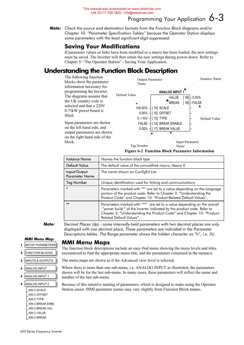
Programming Your Application 6-3
605 Series Frequency Inverter
Note: Check the source and destination formats from the Function Block diagrams and/or Chapter 10: “Parameter Specification Tables” because the Operator Station displays some parameters with the least significant digit suppressed.
Saving Your Modifications If parameter values or links have been modified or a macro has been loaded, the new settings must be saved. The Inverter will then retain the new settings during power-down. Refer to Chapter 5: “The Operator Station” - Saving Your Application.
Understanding the Function Block Description The following function blocks show the parameter information necessary for programming the Inverter. The diagrams assume that the UK country code is selected and that a 220V 0.75kW power board is fitted.
Input parameters are shown on the left hand side, and output parameters are shown on the right hand side of the block.
Instance Name Names the function block type
Default Value The default value of the unmodified macro, Macro 0
Input/Output Parameter Name
The name shown on ConfigEd Lite
Tag Number Unique identification used for linking and communications
* Parameters marked with “*” are set to a value depending on the Language portion of the product code. Refer to Chapter 2: “Understanding the Product Code” and Chapter 10: “Product-Related Default Values”.
** Parameters marked with “**” are set to a value depending on the overall “power build “ of the Inverter indicated by the product code. Refer to Chapter 2: “Understanding the Product Code” and Chapter 10: “Product-Related Default Values”.
Note: Decimal Places (dp) - some internally-held parameters with two decimal places are only displayed with one decimal place. These parameters are indicated in the Parameter Descriptions tables. The Range parameter shows the hidden character as “h”, i.e. (h).
MMI Menu Maps The function block descriptions include an easy-find menu showing the menu levels and titles encountered to find the appropriate menu title, and the parameters contained in the menu(s).
The menu maps are shown as if the Advanced view level is selected.
Where there is more than one sub-menu, i.e. ANALOG INPUT as illustrated, the parameters shown will be for the last sub-menu. In many cases, these parameters will reflect the name and number of the last sub-menu.
Because of this intuitive naming of parameters, which is designed to make using the Operator Station easier, MMI parameter names may vary slightly from Function Block names.
Default Value
Input ParameterName
Output ParameterName
Default Value
Instance Name
ANALOG INPUT 1VALUE [ 16] – 0.00%BREAK [ 18] – FALSE
100.00% – [ 14] SCALE –0.00% – [ 15] OFFSET –
0..+10V – [ 13] TYPE –FALSE – [ 12] BREAK ENABLE –0.00% – [ 17] BREAK VALUE –
Tag NumberFigure 6-2 Function Block Parameter Information
MMI Menu Map
1 SETUP PARAMETERS
2 FUNCTION BLOCKS
3 INPUTS & OUTPUTS
4 ANALOG INPUT
4 ANALOG INPUT 1
4 ANALOG INPUT 2
AIN 2 SCALE
AIN 2 OFFSET
AIN 2 TYPE
AIN 2 BREAK ENBL
AIN 2 BREAK VAL
AIN 2 VALUE
AIN 2 BREAK
This manual was downloaded on www.sdsdrives.com +44 (0)117 938 1800 - [email protected]
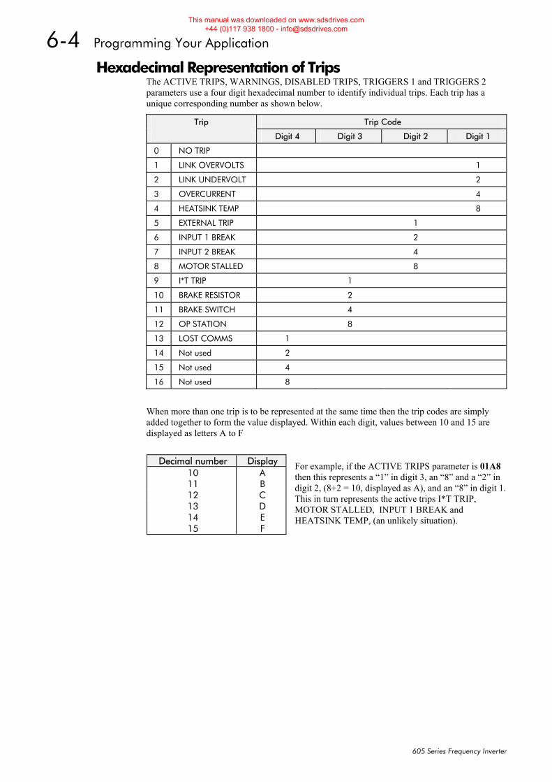
6-4 Programming Your Application
605 Series Frequency Inverter
Hexadecimal Representation of Trips The ACTIVE TRIPS, WARNINGS, DISABLED TRIPS, TRIGGERS 1 and TRIGGERS 2 parameters use a four digit hexadecimal number to identify individual trips. Each trip has a unique corresponding number as shown below.
Trip Trip Code
Digit 4 Digit 3 Digit 2 Digit 1
0 NO TRIP
1 LINK OVERVOLTS 1
2 LINK UNDERVOLT 2
3 OVERCURRENT 4
4 HEATSINK TEMP 8
5 EXTERNAL TRIP 1
6 INPUT 1 BREAK 2
7 INPUT 2 BREAK 4
8 MOTOR STALLED 8
9 I*T TRIP 1
10 BRAKE RESISTOR 2
11 BRAKE SWITCH 4
12 OP STATION 8
13 LOST COMMS 1
14 Not used 2
15 Not used 4
16 Not used 8
When more than one trip is to be represented at the same time then the trip codes are simply added together to form the value displayed. Within each digit, values between 10 and 15 are displayed as letters A to F
For example, if the ACTIVE TRIPS parameter is 01A8 then this represents a “1” in digit 3, an “8” and a “2” in digit 2, (8+2 = 10, displayed as A), and an “8” in digit 1. This in turn represents the active trips I*T TRIP, MOTOR STALLED, INPUT 1 BREAK and HEATSINK TEMP, (an unlikely situation).
Decimal number Display 10 A 11 B 12 C 13 D 14 E 15 F
This manual was downloaded on www.sdsdrives.com +44 (0)117 938 1800 - [email protected]
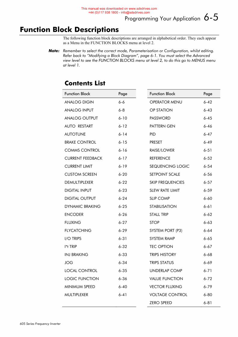
Programming Your Application 6-5
605 Series Frequency Inverter
Function Block Descriptions The following function block descriptions are arranged in alphabetical order. They each appear as a Menu in the FUNCTION BLOCKS menu at level 2.
Note: Remember to select the correct mode, Parameterisation or Configuration, whilst editing. Refer back to “Modifying a Block Diagram”, page 6-1. You must select the Advanced view level to see the FUNCTION BLOCKS menu at level 2, to do this go to MENUS menu at level 1.
Contents List
Function Block Page Function Block Page
ANALOG DIGIN 6-6 OPERATOR MENU 6-42
ANALOG INPUT 6-8 OP STATION 6-43
ANALOG OUTPUT 6-10 PASSWORD 6-45
AUTO RESTART 6-12 PATTERN GEN 6-46
AUTOTUNE 6-14 PID 6-47
BRAKE CONTROL 6-15 PRESET 6-49
COMMS CONTROL 6-16 RAISE/LOWER 6-51
CURRENT FEEDBACK 6-17 REFERENCE 6-52
CURRENT LIMIT 6-19 SEQUENCING LOGIC 6-54
CUSTOM SCREEN 6-20 SETPOINT SCALE 6-56
DEMULTIPLEXER 6-22 SKIP FREQUENCIES 6-57
DIGITAL INPUT 6-23 SLEW RATE LIMIT 6-59
DIGITAL OUTPUT 6-24 SLIP COMP 6-60
DYNAMIC BRAKING 6-25 STABILISATION 6-61
ENCODER 6-26 STALL TRIP 6-62
FLUXING 6-27 STOP 6-63
FLYCATCHING 6-29 SYSTEM PORT (P3) 6-64
I/O TRIPS 6-31 SYSTEM RAMP 6-65
I*t TRIP 6-32 TEC OPTION 6-67
INJ BRAKING 6-33 TRIPS HISTORY 6-68
JOG 6-34 TRIPS STATUS 6-69
LOCAL CONTROL 6-35 UNDERLAP COMP 6-71
LOGIC FUNCTION 6-36 VALUE FUNCTION 6-72
MINIMUM SPEED 6-40 VECTOR FLUXING 6-79
MULTIPLEXER 6-41 VOLTAGE CONTROL 6-80
ZERO SPEED 6-81
This manual was downloaded on www.sdsdrives.com +44 (0)117 938 1800 - [email protected]
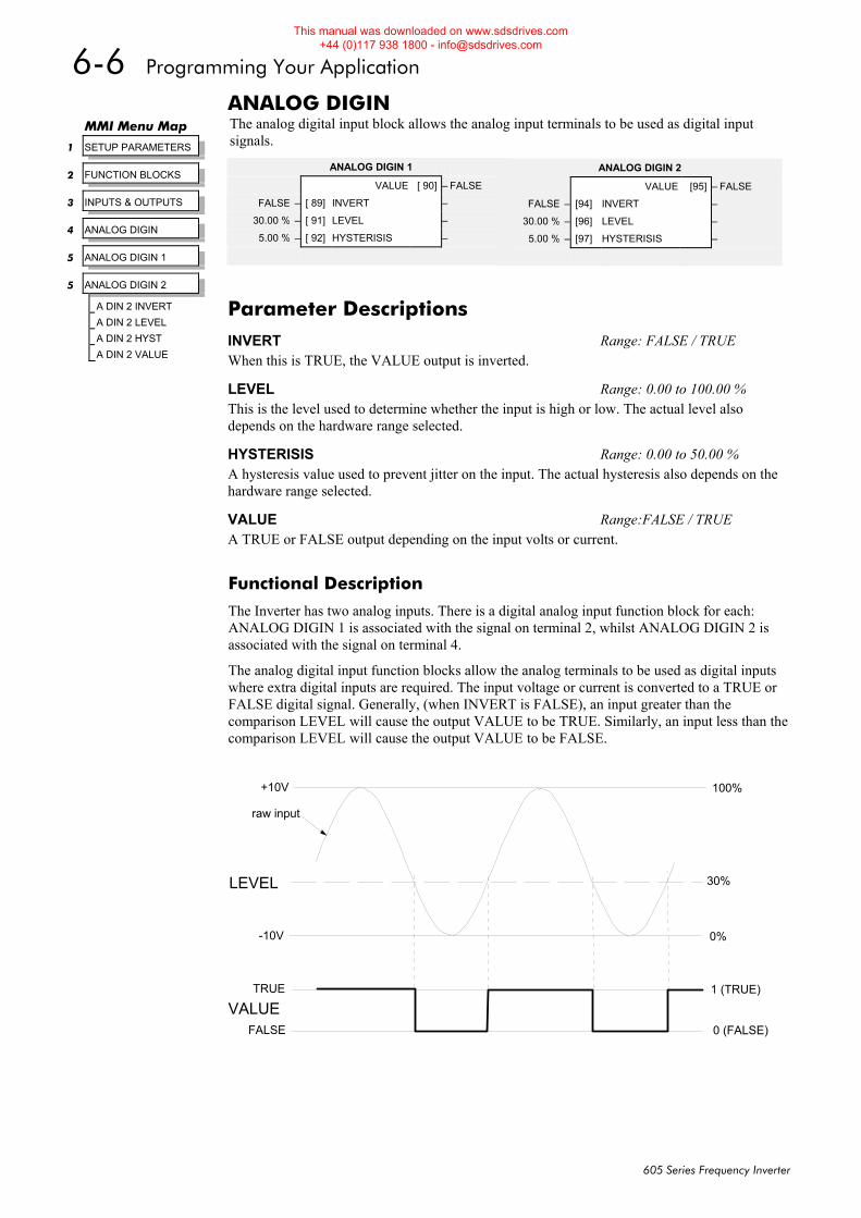
6-6 Programming Your Application
605 Series Frequency Inverter
ANALOG DIGIN The analog digital input block allows the analog input terminals to be used as digital input signals.
Functional Description
The Inverter has two analog inputs. There is a digital analog input function block for each: ANALOG DIGIN 1 is associated with the signal on terminal 2, whilst ANALOG DIGIN 2 is associated with the signal on terminal 4.
The analog digital input function blocks allow the analog terminals to be used as digital inputs where extra digital inputs are required. The input voltage or current is converted to a TRUE or FALSE digital signal. Generally, (when INVERT is FALSE), an input greater than the comparison LEVEL will cause the output VALUE to be TRUE. Similarly, an input less than the comparison LEVEL will cause the output VALUE to be FALSE.
+10V
-10V 0%
30%
100%
0 (FALSE)
1 (TRUE)
LEVEL
TRUE
FALSE
VALUE
raw input
MMI Menu Map
1 SETUP PARAMETERS
2 FUNCTION BLOCKS
3 INPUTS & OUTPUTS
4 ANALOG DIGIN
5 ANALOG DIGIN 1
5 ANALOG DIGIN 2
A DIN 2 INVERT
A DIN 2 LEVEL
A DIN 2 HYST
A DIN 2 VALUE
ANALOG DIGIN 2
VALUE [95] – FALSE
FALSE – [94] INVERT –
30.00 % – [96] LEVEL –
5.00 % – [97] HYSTERISIS –
Parameter Descriptions INVERT Range: FALSE / TRUE When this is TRUE, the VALUE output is inverted.
LEVEL Range: 0.00 to 100.00 % This is the level used to determine whether the input is high or low. The actual level also depends on the hardware range selected.
HYSTERISIS Range: 0.00 to 50.00 % A hysteresis value used to prevent jitter on the input. The actual hysteresis also depends on the hardware range selected.
VALUE Range:FALSE / TRUE A TRUE or FALSE output depending on the input volts or current.
ANALOG DIGIN 1
VALUE [ 90] – FALSE
FALSE – [ 89] INVERT –
30.00 % – [ 91] LEVEL –
5.00 % – [ 92] HYSTERISIS –
This manual was downloaded on www.sdsdrives.com +44 (0)117 938 1800 - [email protected]
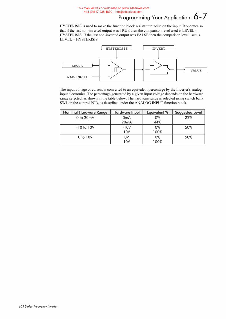
Programming Your Application 6-7
605 Series Frequency Inverter
HYSTERISIS is used to make the function block resistant to noise on the input. It operates so that if the last non-inverted output was TRUE then the comparison level used is LEVEL - HYSTERISIS. If the last non-inverted output was FALSE then the comparison level used is LEVEL + HYSTERISIS.
LEVEL
RAW INPUT
VALUE
INVERTHYSTERISIS
The input voltage or current is converted to an equivalent percentage by the Inverter's analog input electronics. The percentage generated by a given input voltage depends on the hardware range selected, as shown in the table below. The hardware range is selected using switch bank SW1 on the control PCB, as described under the ANALOG INPUT function block.
Nominal Hardware Range Hardware Input Equivalent % Suggested Level 0 to 20mA 0mA
20mA 0%
44% 22%
-10 to 10V -10V 10V
0% 100%
50%
0 to 10V 0V 10V
0% 100%
50%
This manual was downloaded on www.sdsdrives.com +44 (0)117 938 1800 - [email protected]

6-8 Programming Your Application
605 Series Frequency Inverter
ANALOG INPUT The analog input block converts the input voltage or current into a value expressed as a percentage of a configurable range.
MMI Menu Map
1 SETUP PARAMETERS
2 FUNCTION BLOCKS
3 INPUTS & OUTPUTS
4 ANALOG INPUT
5 ANALOG INPUT 1
5 ANALOG INPUT 2
AIN 2 SCALE
AIN 2 OFFSET
AIN 2 TYPE
AIN 2 BREAK ENBL
AIN 2 BREAK VAL
AIN 2 VALUE
AIN 2 BREAK
ANALOG INPUT 1
VALUE [ 16] – 0.00 %
BREAK [ 18] – FALSE
100.00 % – [ 14] SCALE –
0.00 % – [ 15] OFFSET –
0..+10 V – [ 13] TYPE –
FALSE – [ 12] BREAK ENABLE –
0.00 % – [ 17] BREAK VALUE –
ANALOG INPUT 2
VALUE [ 25] – 0.00 %
BREAK [ 27] – FALSE
100.00 % – [ 23] SCALE –
0.00 % – [ 24] OFFSET –
0..+10 V – [ 22] TYPE –
FALSE – [ 21] BREAK ENABLE –
0.00 % – [ 26] BREAK VALUE –
Parameter Descriptions SCALE Range: -300.00 to 300.00 % A scaling factor applied to the raw input. With a scaling factor of 100.00% and an offset of 0.00%, an input equal to the low input range will appear as a value of 0.00%. Similarly, an input equal to the high input range will appear as a value of 100.00%.
OFFSET Range: -300.00 to 300.00 % An offset added to the input after the scaling factor has been applied.
TYPE Range: Enumerated - see below The input range and type. Warning: For correct operation, ensure that the hardware range selected using switch bank SW1 corresponds to the TYPE selected.
Enumerated Value : Type
0 : 0..+10 V 1 : +2..+10 V 2 : 0..+5 V 3 : +1..+5 V 4 : -10..+10 V 5 : 0..20 mA 6 : 4..20 mA 7 : 20..4 mA 8 : 20..0 mA
BREAK ENABLE Range: FALSE / TRUE For input types that support sensor break detection, this parameter may be used to disable sensor break detection. For input types that do not support break detection, this parameter is FALSE.
BREAK VALUE Range: -300.00 to 300.00 % The value that will appear as the VALUE output when BREAK is TRUE
VALUE Range: xxx.xx % The input reading with scaling and offset applied.
BREAK Range: FALSE / TRUE Indicates that the input sensor signal is not present. See below for more details on break detection.
This manual was downloaded on www.sdsdrives.com +44 (0)117 938 1800 - [email protected]
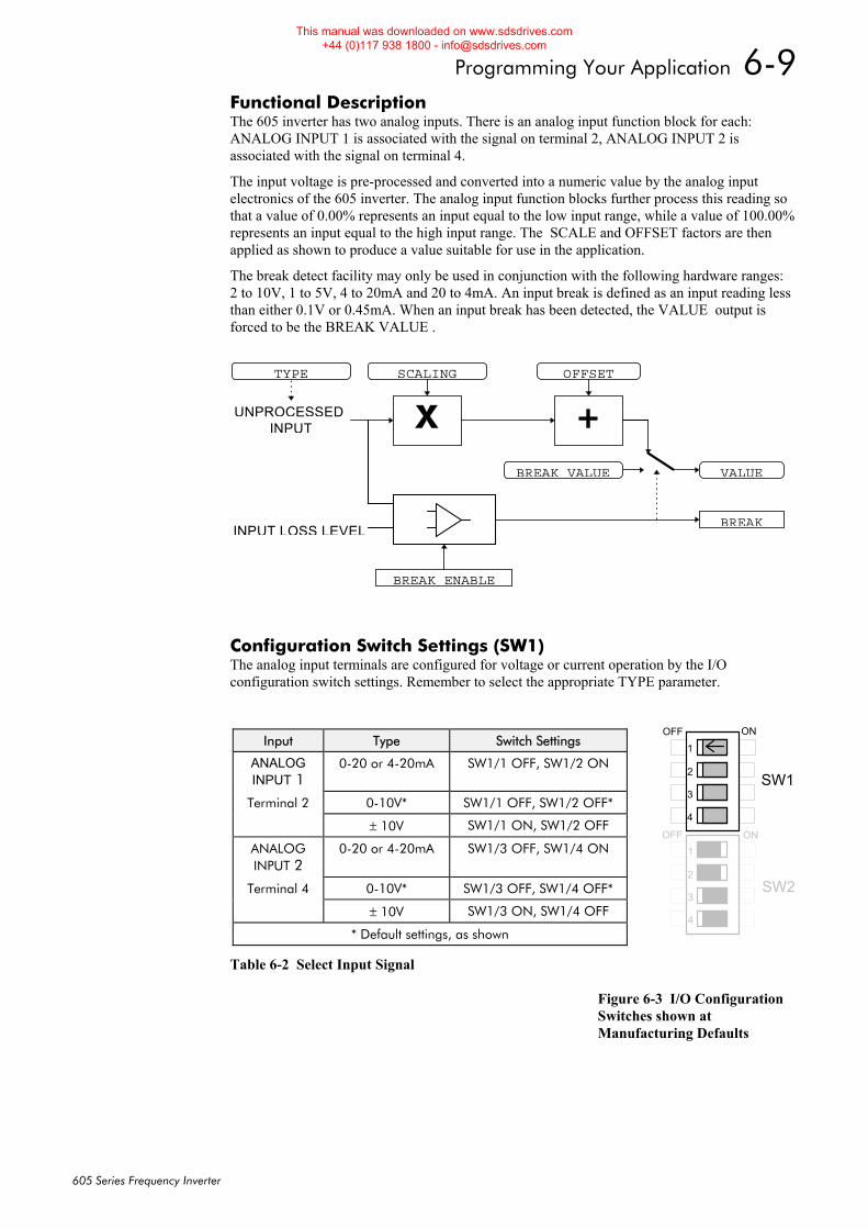
Programming Your Application 6-9
605 Series Frequency Inverter
Functional Description The 605 inverter has two analog inputs. There is an analog input function block for each: ANALOG INPUT 1 is associated with the signal on terminal 2, ANALOG INPUT 2 is associated with the signal on terminal 4.
The input voltage is pre-processed and converted into a numeric value by the analog input electronics of the 605 inverter. The analog input function blocks further process this reading so that a value of 0.00% represents an input equal to the low input range, while a value of 100.00% represents an input equal to the high input range. The SCALE and OFFSET factors are then applied as shown to produce a value suitable for use in the application.
The break detect facility may only be used in conjunction with the following hardware ranges: 2 to 10V, 1 to 5V, 4 to 20mA and 20 to 4mA. An input break is defined as an input reading less than either 0.1V or 0.45mA. When an input break has been detected, the VALUE output is forced to be the BREAK VALUE .
Configuration Switch Settings (SW1) The analog input terminals are configured for voltage or current operation by the I/O configuration switch settings. Remember to select the appropriate TYPE parameter.
Table 6-2 Select Input Signal Figure 6-3 I/O Configuration Switches shown at Manufacturing Defaults
+
VALUE
SCALING OFFSET
XINPUT
BREAK VALUE
INPUT LOSS LEVEL
BREAK ENABLE
BREAK
TYPE
UNPROCESSED
Input Type Switch Settings
ANALOG INPUT 1
0-20 or 4-20mA SW1/1 OFF, SW1/2 ON
Terminal 2 0-10V* SW1/1 OFF, SW1/2 OFF*
± 10V SW1/1 ON, SW1/2 OFF
ANALOG INPUT 2
0-20 or 4-20mA SW1/3 OFF, SW1/4 ON
Terminal 4 0-10V* SW1/3 OFF, SW1/4 OFF*
± 10V SW1/3 ON, SW1/4 OFF
* Default settings, as shown
SW1
SW2
1
2
3
4
1
2
3
4
ON
ON
OFF
OFF
This manual was downloaded on www.sdsdrives.com +44 (0)117 938 1800 - [email protected]
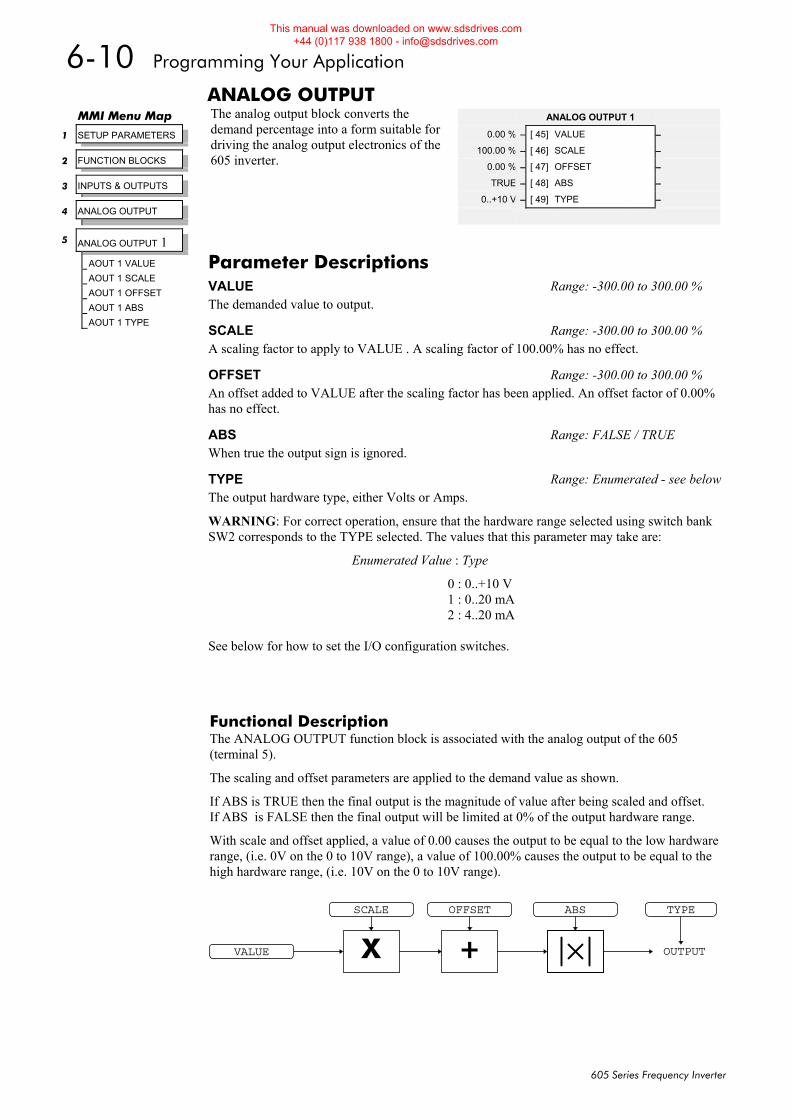
6-10 Programming Your Application
605 Series Frequency Inverter
ANALOG OUTPUT The analog output block converts the demand percentage into a form suitable for driving the analog output electronics of the 605 inverter.
Functional Description The ANALOG OUTPUT function block is associated with the analog output of the 605 (terminal 5).
The scaling and offset parameters are applied to the demand value as shown.
If ABS is TRUE then the final output is the magnitude of value after being scaled and offset. If ABS is FALSE then the final output will be limited at 0% of the output hardware range.
With scale and offset applied, a value of 0.00 causes the output to be equal to the low hardware range, (i.e. 0V on the 0 to 10V range), a value of 100.00% causes the output to be equal to the high hardware range, (i.e. 10V on the 0 to 10V range).
MMI Menu Map
1 SETUP PARAMETERS
2 FUNCTION BLOCKS
3 INPUTS & OUTPUTS
4 ANALOG OUTPUT
5 ANALOG OUTPUT 1
AOUT 1 VALUE
AOUT 1 SCALE
AOUT 1 OFFSET
AOUT 1 ABS
AOUT 1 TYPE
ANALOG OUTPUT 1
0.00 % – [ 45] VALUE –
100.00 % – [ 46] SCALE –
0.00 % – [ 47] OFFSET –
TRUE – [ 48] ABS –
0..+10 V – [ 49] TYPE –
Parameter Descriptions VALUE Range: -300.00 to 300.00 % The demanded value to output.
SCALE Range: -300.00 to 300.00 % A scaling factor to apply to VALUE . A scaling factor of 100.00% has no effect.
OFFSET Range: -300.00 to 300.00 % An offset added to VALUE after the scaling factor has been applied. An offset factor of 0.00% has no effect.
ABS Range: FALSE / TRUE When true the output sign is ignored.
TYPE Range: Enumerated - see belowThe output hardware type, either Volts or Amps.
WARNING: For correct operation, ensure that the hardware range selected using switch bank SW2 corresponds to the TYPE selected. The values that this parameter may take are:
Enumerated Value : Type
0 : 0..+10 V 1 : 0..20 mA 2 : 4..20 mA
See below for how to set the I/O configuration switches.
X OUTPUT
SCALE
+
OFFSET
VALUE
ABS TYPE
This manual was downloaded on www.sdsdrives.com +44 (0)117 938 1800 - [email protected]
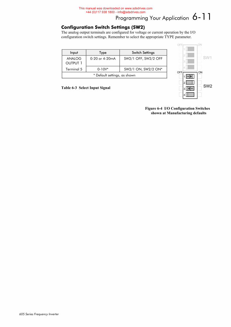
Programming Your Application 6-11
605 Series Frequency Inverter
Configuration Switch Settings (SW2) The analog output terminals are configured for voltage or current operation by the I/O configuration switch settings. Remember to select the appropriate TYPE parameter.
Table 6-3 Select Input Signal
Figure 6-4 I/O Configuration Switches shown at Manufacturing defaults
Input Type Switch Settings
ANALOG OUTPUT 1
0-20 or 4-20mA SW2/1 OFF, SW2/2 OFF
Terminal 5 0-10V* SW2/1 ON, SW2/2 ON*
* Default settings, as shown
SW1
SW2
1
2
3
4
1
2
3
4
ON
ON
OFF
OFF
This manual was downloaded on www.sdsdrives.com +44 (0)117 938 1800 - [email protected]
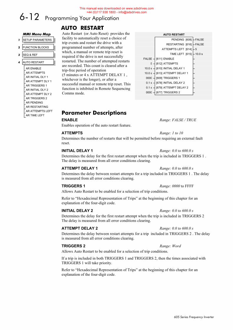
6-12 Programming Your Application
605 Series Frequency Inverter
AUTO RESTART Auto Restart (or Auto Reset) provides the facility to automatically reset a choice of trip events and restart the drive with a programmed number of attempts, after which, a manual or remote trip reset is required if the drive is not successfully restarted. The number of attempted restarts are recorded. This count is cleared after a trip-free period of operation (5 minutes or 4 x ATTEMPT DELAY 1 , whichever is the longer), or after a successful manual or remote trip reset. This function is inhibited in Remote Sequencing Comms mode.
MMI Menu Map
1 SETUP PARAMETERS
2 FUNCTION BLOCKS
3 SEQ & REF
4 AUTO RESTART
AR ENABLE AR ATTEMPTS AR INITIAL DLY 1 AR ATTEMPT DLY 1 AR TRIGGERS 1 AR INITIAL DLY 2 AR ATTEMPT DLY 2 AR TRIGGERS 2 AR PENDING AR RESTARTING AR ATTEMPTS LEFT AR TIME LEFT
AUTO RESTART
PENDING [608] – FALSE
RESTARTING [616] – FALSE
ATTEMPTS LEFT [614] – 5
TIME LEFT [615] – 10.0 s
FALSE – [611] ENABLE –
5 – [612] ATTEMPTS –
10.0 s – [610] INITIAL DELAY 1 –
10.0 s – [613] ATTEMPT DELAY 1 –
0000 – [609] TRIGGERS 1 –
0.1 s – [678] INITIAL DELAY 2 –
0.1 s – [679] ATTEMPT DELAY 2 –
0000 – [677] TRIGGERS 2 –
Parameter Descriptions ENABLE Range: FALSE / TRUE Enables operation of the auto restart feature.
ATTEMPTS Range: 1 to 10 Determines the number of restarts that will be permitted before requiring an external fault reset.
INITIAL DELAY 1 Range: 0.0 to 600.0 s Determines the delay for the first restart attempt when the trip is included in TRIGGERS 1 . The delay is measured from all error conditions clearing.
ATTEMPT DELAY 1 Range: 0.0 to 600.0 s Determines the delay between restart attempts for a trip included in TRIGGERS 1 . The delay is measured from all error conditions clearing.
TRIGGERS 1 Range: 0000 to FFFF Allows Auto Restart to be enabled for a selection of trip conditions.
Refer to “Hexadecimal Representation of Trips” at the beginning of this chapter for an explanation of the four-digit code.
INITIAL DELAY 2 Range: 0.0 to 600.0 s Determines the delay for the first restart attempt when the trip is included in TRIGGERS 2 The delay is measured from all error conditions clearing.
ATTEMPT DELAY 2 Range: 0.0 to 600.0 s Determines the delay between restart attempts for a trip included in TRIGGERS 2 . The delay is measured from all error conditions clearing.
TRIGGERS 2 Range: Word Allows Auto Restart to be enabled for a selection of trip conditions.
If a trip is included in both TRIGGERS 1 and TRIGGERS 2, then the times associated with TRIGGERS 1 will take priority.
Refer to “Hexadecimal Representation of Trips” at the beginning of this chapter for an explanation of the four-digit code.
This manual was downloaded on www.sdsdrives.com +44 (0)117 938 1800 - [email protected]

Programming Your Application 6-13
605 Series Frequency Inverter
PENDING Range: FALSE / TRUE Indicates that an auto restart will occur after the programmed delay.
RESTARTING Range: FALSE / TRUE Indicates that an auto restart is occuring. ATTEMPTS LEFT Range: xxxxx Indicates the number of attempts left before an external fault reset is required.
TIME LEFT Range: xxxx.x s When in the timing sub-state, this parameter indicates the time left before an auto restart attempt will be permitted. When non-zero, this value is unaffected by changes to ATTEMPT DELAY 1.
This manual was downloaded on www.sdsdrives.com +44 (0)117 938 1800 - [email protected]
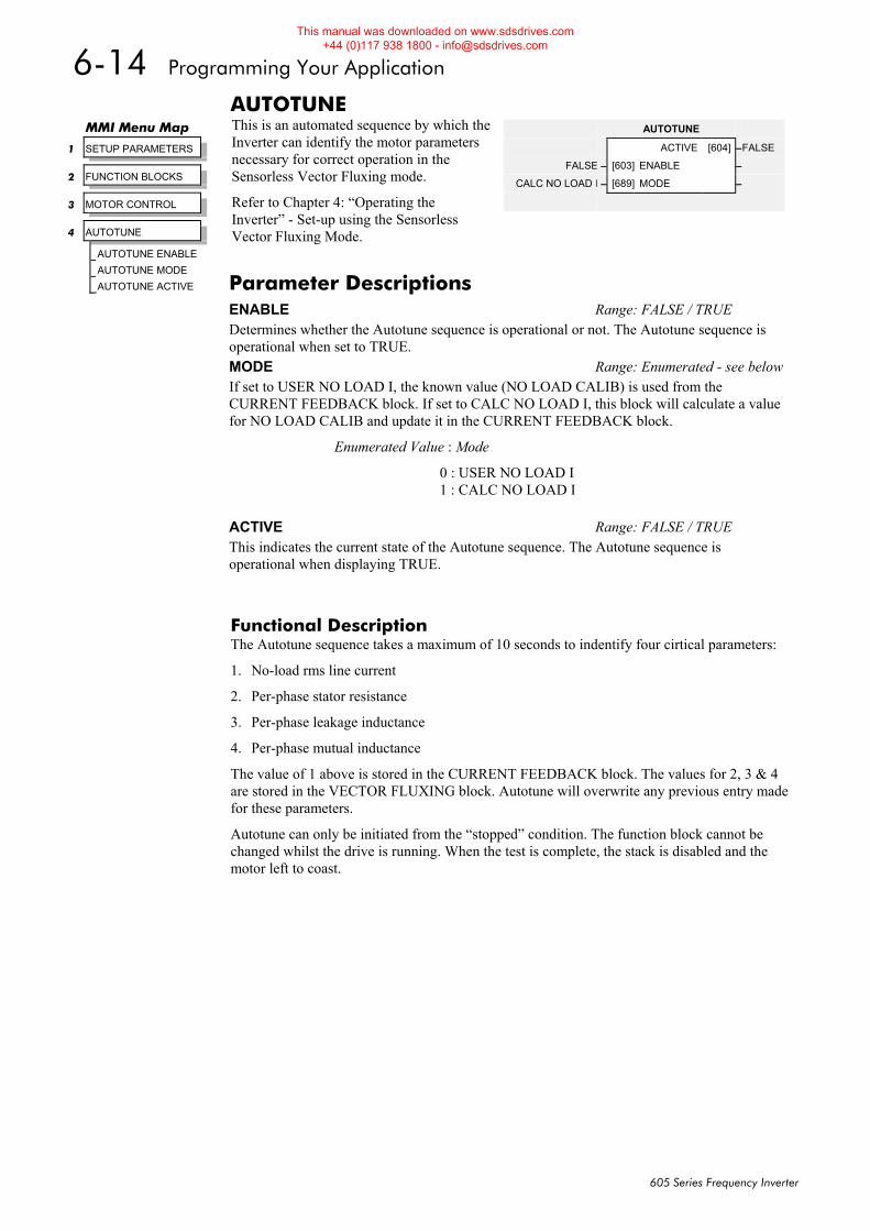
6-14 Programming Your Application
605 Series Frequency Inverter
AUTOTUNE This is an automated sequence by which the Inverter can identify the motor parameters necessary for correct operation in the Sensorless Vector Fluxing mode.
Refer to Chapter 4: “Operating the Inverter” - Set-up using the Sensorless Vector Fluxing Mode.
Functional Description The Autotune sequence takes a maximum of 10 seconds to indentify four cirtical parameters:
1. No-load rms line current
2. Per-phase stator resistance
3. Per-phase leakage inductance
4. Per-phase mutual inductance
The value of 1 above is stored in the CURRENT FEEDBACK block. The values for 2, 3 & 4 are stored in the VECTOR FLUXING block. Autotune will overwrite any previous entry made for these parameters.
Autotune can only be initiated from the “stopped” condition. The function block cannot be changed whilst the drive is running. When the test is complete, the stack is disabled and the motor left to coast.
MMI Menu Map
1 SETUP PARAMETERS
2 FUNCTION BLOCKS
3 MOTOR CONTROL
4 AUTOTUNE
AUTOTUNE ENABLE
AUTOTUNE MODE
AUTOTUNE ACTIVE
AUTOTUNE
ACTIVE [604] –FALSE
FALSE – [603] ENABLE –
CALC NO LOAD I – [689] MODE –
Parameter Descriptions ENABLE Range: FALSE / TRUE Determines whether the Autotune sequence is operational or not. The Autotune sequence is operational when set to TRUE. MODE Range: Enumerated - see belowIf set to USER NO LOAD I, the known value (NO LOAD CALIB) is used from the CURRENT FEEDBACK block. If set to CALC NO LOAD I, this block will calculate a value for NO LOAD CALIB and update it in the CURRENT FEEDBACK block.
Enumerated Value : Mode
0 : USER NO LOAD I 1 : CALC NO LOAD I
ACTIVE Range: FALSE / TRUE This indicates the current state of the Autotune sequence. The Autotune sequence is operational when displaying TRUE.
This manual was downloaded on www.sdsdrives.com +44 (0)117 938 1800 - [email protected]
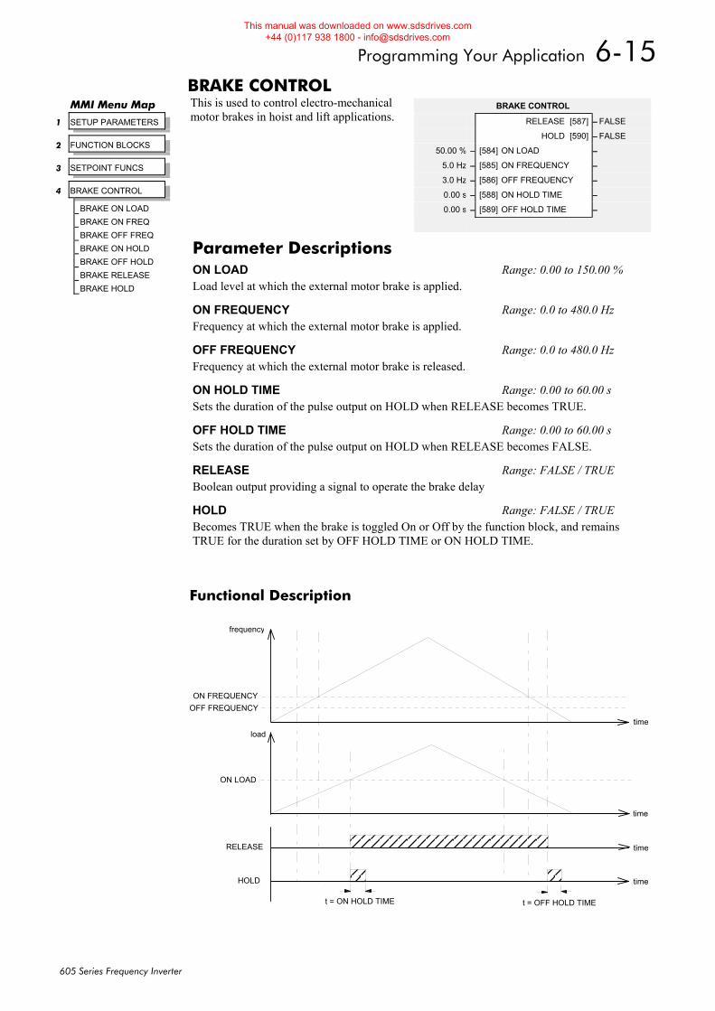
Programming Your Application 6-15
605 Series Frequency Inverter
BRAKE CONTROL This is used to control electro-mechanical motor brakes in hoist and lift applications.
Functional Description
time
time
time
time
frequency
ON FREQUENCYOFF FREQUENCY
RELEASE
HOLD
ON LOAD
load
t = ON HOLD TIME t = OFF HOLD TIME
MMI Menu Map
1 SETUP PARAMETERS
2 FUNCTION BLOCKS
3 SETPOINT FUNCS
4 BRAKE CONTROL
BRAKE ON LOAD
BRAKE ON FREQ
BRAKE OFF FREQ
BRAKE ON HOLD
BRAKE OFF HOLD
BRAKE RELEASE
BRAKE HOLD
BRAKE CONTROL
RELEASE [587] – FALSE
HOLD [590] – FALSE
50.00 % – [584] ON LOAD –
5.0 Hz – [585] ON FREQUENCY –
3.0 Hz – [586] OFF FREQUENCY –
0.00 s – [588] ON HOLD TIME –
0.00 s – [589] OFF HOLD TIME –
Parameter Descriptions ON LOAD Range: 0.00 to 150.00 % Load level at which the external motor brake is applied.
ON FREQUENCY Range: 0.0 to 480.0 Hz Frequency at which the external motor brake is applied.
OFF FREQUENCY Range: 0.0 to 480.0 Hz Frequency at which the external motor brake is released.
ON HOLD TIME Range: 0.00 to 60.00 s Sets the duration of the pulse output on HOLD when RELEASE becomes TRUE.
OFF HOLD TIME Range: 0.00 to 60.00 s Sets the duration of the pulse output on HOLD when RELEASE becomes FALSE.
RELEASE Range: FALSE / TRUE Boolean output providing a signal to operate the brake delay
HOLD Range: FALSE / TRUE Becomes TRUE when the brake is toggled On or Off by the function block, and remains TRUE for the duration set by OFF HOLD TIME or ON HOLD TIME.
This manual was downloaded on www.sdsdrives.com +44 (0)117 938 1800 - [email protected]
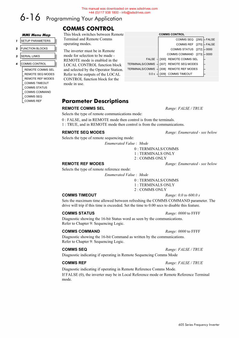
6-16 Programming Your Application
605 Series Frequency Inverter
COMMS CONTROL This block switches between Remote Terminal and Remote Comms operating modes.
The inverter must be in Remote mode for selection to be made - REMOTE mode is enabled in the LOCAL CONTROL function block and selected by the Operator Station. Refer to the outputs of the LOCAL CONTROL function block for the mode in use.
MMI Menu Map
1 SETUP PARAMETERS
2 FUNCTION BLOCKS
3 SERIAL LINKS
4 COMMS CONTROL
REMOTE COMMS SEL
REMOTE SEQ MODES
REMOTE REF MODES
COMMS TIMEOUT
COMMS STATUS
COMMS COMMAND
COMMS SEQ
COMMS REF
COMMS CONTROL
COMMS SEQ [295] – FALSE
COMMS REF [270] – FALSE
COMMS STATUS [272] – 0000
COMMS COMMAND [273] – 0000
FALSE – [300] REMOTE COMMS SEL –
TERMINALS/COMMS – [307] REMOTE SEQ MODES –
TERMINALS/COMMS – [308] REMOTE REF MODES –
0.0 s – [309] COMMS TIMEOUT –
Parameter Descriptions REMOTE COMMS SEL Range: FALSE / TRUE Selects the type of remote communications mode: 0 : FALSE, and in REMOTE mode then control is from the terminals. 1 : TRUE, and in REMOTE mode then control is from the communications.
REMOTE SEQ MODES Range: Enumerated - see belowSelects the type of remote sequencing mode:
Enumerated Value : Mode 0 : TERMINALS/COMMS 1 : TERMINALS ONLY 2 : COMMS ONLY
REMOTE REF MODES Range: Enumerated - see belowSelects the type of remote reference mode:
Enumerated Value : Mode 0 : TERMINALS/COMMS 1 : TERMINALS ONLY 2 : COMMS ONLY
COMMS TIMEOUT Range: 0.0 to 600.0 s Sets the maximum time allowed between refreshing the COMMS COMMAND parameter. The drive will trip if this time is exceeded. Set the time to 0.00 secs to disable this feature.
COMMS STATUS Range: 0000 to FFFF Diagnostic showing the 16-bit Status word as seen by the communications. Refer to Chapter 9: Sequencing Logic.
COMMS COMMAND Range: 0000 to FFFF Diagnostic showing the 16-bit Command as written by the communications. Refer to Chapter 9: Sequencing Logic.
COMMS SEQ Range: FALSE / TRUE Diagnostic indicating if operating in Remote Sequencing Comms Mode
COMMS REF Range: FALSE / TRUE Diagnostic indicating if operating in Remote Reference Comms Mode. If FALSE (0), the inverter may be in Local Reference mode or Remote Reference Terminal mode.
This manual was downloaded on www.sdsdrives.com +44 (0)117 938 1800 - [email protected]
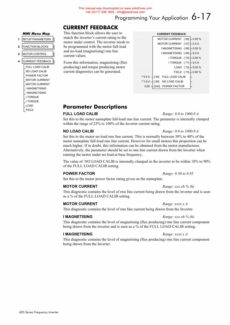
Programming Your Application 6-17
605 Series Frequency Inverter
CURRENT FEEDBACK This function block allows the user to match the inverter’s current rating to the motor under control. The inverter needs to be programmed with the motor full-load and no-load (magnetising) rms line current values.
From this information, magnetising (flux producing) and torque producing motor current diagnostics can be generated.
MMI Menu Map
1 SETUP PARAMETERS
2 FUNCTION BLOCKS
3 MOTOR CONTROL
4 CURRENT FEEDBACK
FULL LOAD CALIB
NO LOAD CALIB
POWER FACTOR
MOTOR CURRENT
MOTOR CURRENT
I MAGNETISING
I MAGNETISING
I TORQUE
I TORQUE
LOAD
FIELD
CURRENT FEEDBACK
MOTOR CURRENT [ 66] – 0.00 %
MOTOR CURRENT [ 67] – 0.0 A
I MAGNETISING [ 68] – 0.00 %
I MAGNETISING [ 69] – 0.0 A
I TORQUE [ 70] – 0.00 %
I TORQUE [ 71] – 0.0 A
LOAD [ 72] – 0.00 %
FIELD [ 73] – 0.00 %
**3.4 A – [ 64] FULL LOAD CALIB –
**1.9 A – [ 65] NO LOAD CALIB –
0.80 – [242] POWER FACTOR –
Parameter Descriptions FULL LOAD CALIB Range: 0.0 to 1000.0 A Set this to the motor nameplate full-load rms line current. The parameter is internally clamped within the range of 25% to 100% of the inverter current rating.
NO LOAD CALIB Range: 0.0 to 1000.0 A Set this to the motor no-load rms line current. This is normally between 30% to 40% of the motor nameplate full-load rms line current. However for small motors this proportion can be much higher. If in doubt, this information can be obtained from the motor manufacturer. Alternatively, the parameter should be set to rms line current drawn from the Inverter when running the motor under no-load at base frequency.
The value of NO LOAD CALIB is internally clamped in the inverter to be within 10% to 90% of the FULL LOAD CALIB setting.
POWER FACTOR Range: 0.50 to 0.95 Set this to the motor power factor rating given on the nameplate.
MOTOR CURRENT Range: xxx.xh % (h) This diagnostic contains the level of rms line current being drawn from the inverter and is seen as a % of the FULL LOAD CALIB setting.
MOTOR CURRENT Range: xxxx.x A This diagnostic contains the level of rms line current being drawn from the Inverter.
I MAGNETISING Range: xxx.xh % (h) This diagnostic contains the level of magnetising (flux producing) rms line current component being drawn from the inverter and is seen as a % of the FULL LOAD CALIB setting.
I MAGNETISING Range: xxxx.x A This diagnostic contains the level of magnetising (flux producing) rms line current component being drawn from the Inverter.
This manual was downloaded on www.sdsdrives.com +44 (0)117 938 1800 - [email protected]
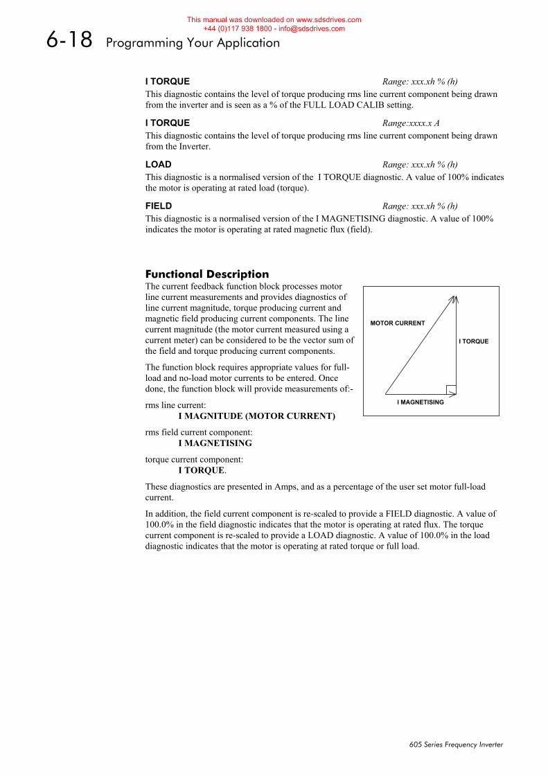
6-18 Programming Your Application
605 Series Frequency Inverter
Functional Description The current feedback function block processes motor line current measurements and provides diagnostics of line current magnitude, torque producing current and magnetic field producing current components. The line current magnitude (the motor current measured using a current meter) can be considered to be the vector sum of the field and torque producing current components.
The function block requires appropriate values for full-load and no-load motor currents to be entered. Once done, the function block will provide measurements of:-
rms line current: I MAGNITUDE (MOTOR CURRENT)
rms field current component: I MAGNETISING
torque current component: I TORQUE.
These diagnostics are presented in Amps, and as a percentage of the user set motor full-load current.
In addition, the field current component is re-scaled to provide a FIELD diagnostic. A value of 100.0% in the field diagnostic indicates that the motor is operating at rated flux. The torque current component is re-scaled to provide a LOAD diagnostic. A value of 100.0% in the load diagnostic indicates that the motor is operating at rated torque or full load.
I TORQUE Range: xxx.xh % (h) This diagnostic contains the level of torque producing rms line current component being drawn from the inverter and is seen as a % of the FULL LOAD CALIB setting.
I TORQUE Range:xxxx.x A This diagnostic contains the level of torque producing rms line current component being drawn from the Inverter.
LOAD Range: xxx.xh % (h) This diagnostic is a normalised version of the I TORQUE diagnostic. A value of 100% indicates the motor is operating at rated load (torque).
FIELD Range: xxx.xh % (h) This diagnostic is a normalised version of the I MAGNETISING diagnostic. A value of 100% indicates the motor is operating at rated magnetic flux (field).
I TORQUE
I MAGNETISING
MOTOR CURRENT
This manual was downloaded on www.sdsdrives.com +44 (0)117 938 1800 - [email protected]
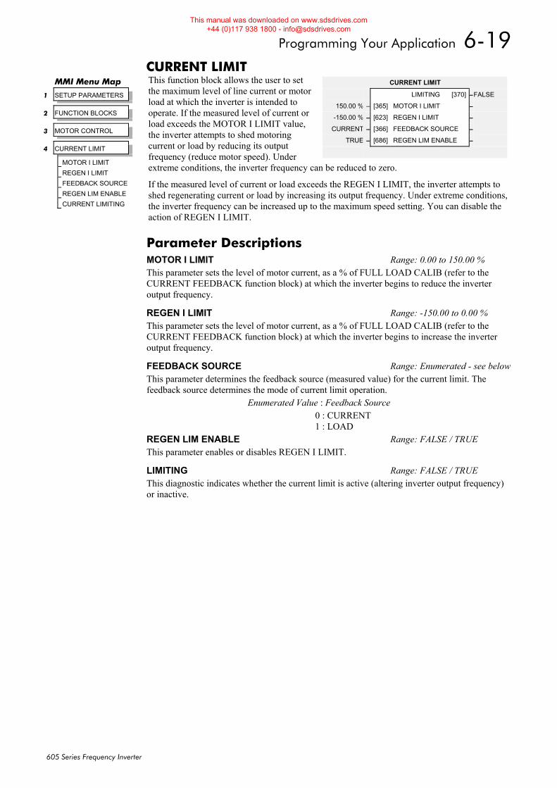
Programming Your Application 6-19
605 Series Frequency Inverter
CURRENT LIMIT This function block allows the user to set the maximum level of line current or motor load at which the inverter is intended to operate. If the measured level of current or load exceeds the MOTOR I LIMIT value, the inverter attempts to shed motoring current or load by reducing its output frequency (reduce motor speed). Under extreme conditions, the inverter frequency can be reduced to zero.
If the measured level of current or load exceeds the REGEN I LIMIT, the inverter attempts to shed regenerating current or load by increasing its output frequency. Under extreme conditions, the inverter frequency can be increased up to the maximum speed setting. You can disable the action of REGEN I LIMIT.
MMI Menu Map
1 SETUP PARAMETERS
2 FUNCTION BLOCKS
3 MOTOR CONTROL
4 CURRENT LIMIT
MOTOR I LIMIT
REGEN I LIMIT
FEEDBACK SOURCE
REGEN LIM ENABLE
CURRENT LIMITING
CURRENT LIMIT
LIMITING [370] –FALSE
150.00 % – [365] MOTOR I LIMIT –
-150.00 % – [623] REGEN I LIMIT –
CURRENT – [366] FEEDBACK SOURCE –
TRUE – [686] REGEN LIM ENABLE –
Parameter Descriptions MOTOR I LIMIT Range: 0.00 to 150.00 % This parameter sets the level of motor current, as a % of FULL LOAD CALIB (refer to the CURRENT FEEDBACK function block) at which the inverter begins to reduce the inverter output frequency.
REGEN I LIMIT Range: -150.00 to 0.00 % This parameter sets the level of motor current, as a % of FULL LOAD CALIB (refer to the CURRENT FEEDBACK function block) at which the inverter begins to increase the inverter output frequency.
FEEDBACK SOURCE Range: Enumerated - see belowThis parameter determines the feedback source (measured value) for the current limit. The feedback source determines the mode of current limit operation.
Enumerated Value : Feedback Source 0 : CURRENT 1 : LOAD
REGEN LIM ENABLE Range: FALSE / TRUE This parameter enables or disables REGEN I LIMIT.
LIMITING Range: FALSE / TRUE This diagnostic indicates whether the current limit is active (altering inverter output frequency) or inactive.
This manual was downloaded on www.sdsdrives.com +44 (0)117 938 1800 - [email protected]
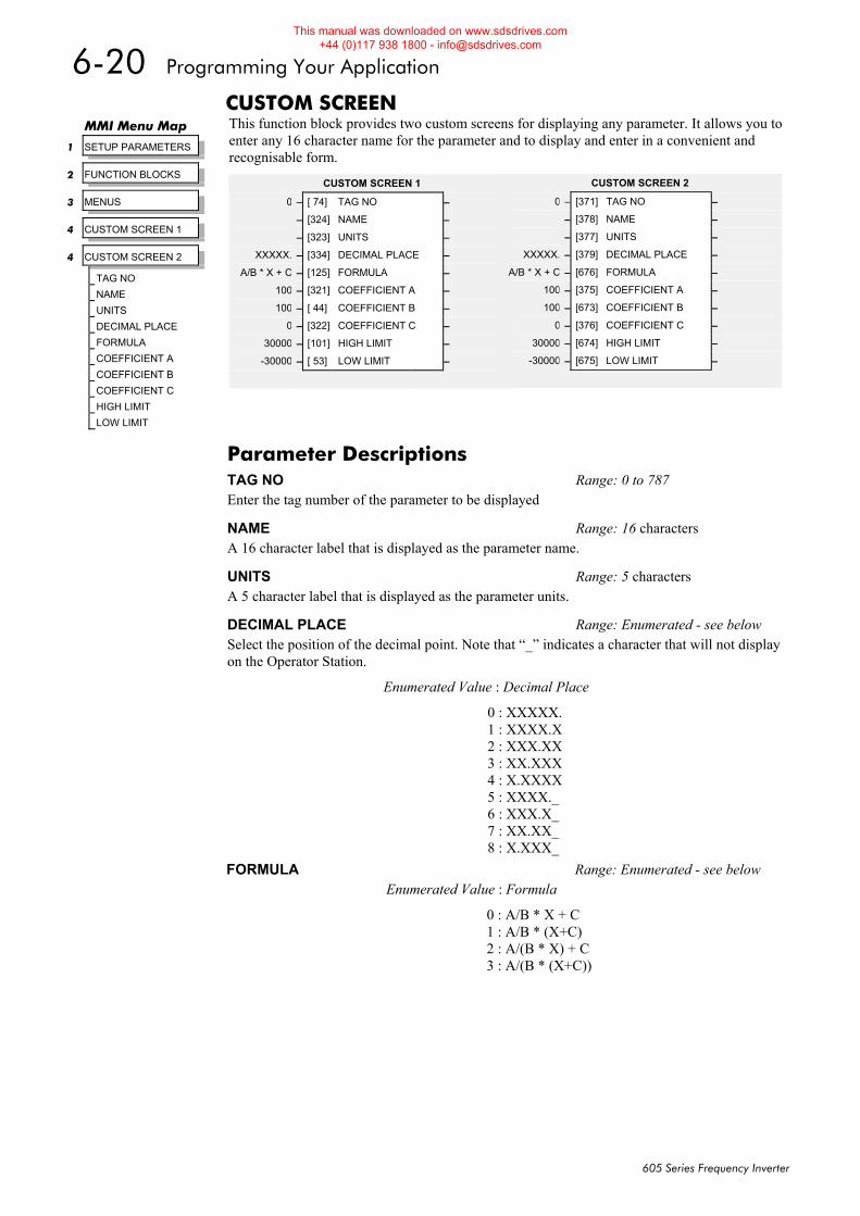
6-20 Programming Your Application
605 Series Frequency Inverter
CUSTOM SCREEN This function block provides two custom screens for displaying any parameter. It allows you to enter any 16 character name for the parameter and to display and enter in a convenient and recognisable form.
MMI Menu Map
1 SETUP PARAMETERS
2 FUNCTION BLOCKS
3 MENUS
4 CUSTOM SCREEN 1
4 CUSTOM SCREEN 2
TAG NO
NAME
UNITS
DECIMAL PLACE
FORMULA
COEFFICIENT A
COEFFICIENT B
COEFFICIENT C
HIGH LIMIT
LOW LIMIT
Parameter Descriptions TAG NO Range: 0 to 787 Enter the tag number of the parameter to be displayed
NAME Range: 16 characters A 16 character label that is displayed as the parameter name.
UNITS Range: 5 characters A 5 character label that is displayed as the parameter units.
DECIMAL PLACE Range: Enumerated - see below Select the position of the decimal point. Note that “_” indicates a character that will not display on the Operator Station.
Enumerated Value : Decimal Place
0 : XXXXX. 1 : XXXX.X 2 : XXX.XX 3 : XX.XXX 4 : X.XXXX 5 : XXXX._ 6 : XXX.X_ 7 : XX.XX_ 8 : X.XXX_
CUSTOM SCREEN 1
0 – [ 74] TAG NO –
– [324] NAME –
– [323] UNITS –
XXXXX. – [334] DECIMAL PLACE –
A/B * X + C – [125] FORMULA –
100 – [321] COEFFICIENT A –
100 – [ 44] COEFFICIENT B –
0 – [322] COEFFICIENT C –
30000 – [101] HIGH LIMIT –
-30000 – [ 53] LOW LIMIT –
CUSTOM SCREEN 2
0 – [371] TAG NO –
– [378] NAME –
– [377] UNITS –
XXXXX. – [379] DECIMAL PLACE –
A/B * X + C – [676] FORMULA –
100 – [375] COEFFICIENT A –
100 – [673] COEFFICIENT B –
0 – [376] COEFFICIENT C –
30000 – [674] HIGH LIMIT –
-30000 – [675] LOW LIMIT –
FORMULA Range: Enumerated - see below Enumerated Value : Formula
0 : A/B * X + C 1 : A/B * (X+C) 2 : A/(B * X) + C 3 : A/(B * (X+C))
This manual was downloaded on www.sdsdrives.com +44 (0)117 938 1800 - [email protected]
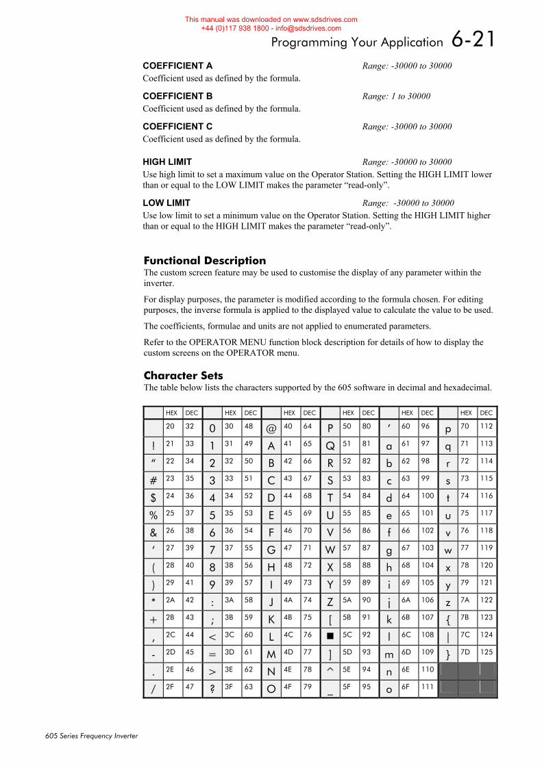
Programming Your Application 6-21
605 Series Frequency Inverter
Functional Description The custom screen feature may be used to customise the display of any parameter within the inverter.
For display purposes, the parameter is modified according to the formula chosen. For editing purposes, the inverse formula is applied to the displayed value to calculate the value to be used.
The coefficients, formulae and units are not applied to enumerated parameters.
Refer to the OPERATOR MENU function block description for details of how to display the custom screens on the OPERATOR menu.
Character Sets The table below lists the characters supported by the 605 software in decimal and hexadecimal.
COEFFICIENT A Range: -30000 to 30000 Coefficient used as defined by the formula.
COEFFICIENT B Range: 1 to 30000 Coefficient used as defined by the formula.
COEFFICIENT C Range: -30000 to 30000 Coefficient used as defined by the formula.
HIGH LIMIT Range: -30000 to 30000 Use high limit to set a maximum value on the Operator Station. Setting the HIGH LIMIT lower than or equal to the LOW LIMIT makes the parameter “read-only”.
LOW LIMIT Range: -30000 to 30000 Use low limit to set a minimum value on the Operator Station. Setting the HIGH LIMIT higher than or equal to the HIGH LIMIT makes the parameter “read-only”.
HEX DEC HEX DEC HEX DEC HEX DEC HEX DEC HEX DEC
20 32 0 30 48 @ 40 64 P 50 80 ’ 60 96 p 70 112
! 21 33 1 31 49 A 41 65 Q 51 81 a 61 97 q 71 113
“ 22 34 2 32 50 B 42 66 R 52 82 b 62 98 r 72 114
# 23 35 3 33 51 C 43 67 S 53 83 c 63 99 s 73 115
$ 24 36 4 34 52 D 44 68 T 54 84 d 64 100 t 74 116
% 25 37 5 35 53 E 45 69 U 55 85 e 65 101 u 75 117
& 26 38 6 36 54 F 46 70 V 56 86 f 66 102 v 76 118
‘ 27 39 7 37 55 G 47 71 W 57 87 g 67 103 w 77 119
( 28 40 8 38 56 H 48 72 X 58 88 h 68 104 x 78 120
) 29 41 9 39 57 I 49 73 Y 59 89 i 69 105 y 79 121
* 2A 42 : 3A 58 J 4A 74 Z 5A 90 j 6A 106 z 7A 122
+ 2B 43 ; 3B 59 K 4B 75 [ 5B 91 k 6B 107 { 7B 123
, 2C 44 < 3C 60 L 4C 76 5C 92 l 6C 108 | 7C 124
- 2D 45 = 3D 61 M 4D 77 ] 5D 93 m 6D 109 } 7D 125
. 2E 46 > 3E 62 N 4E 78 ^ 5E 94 n 6E 110
/ 2F 47 ? 3F 63 O 4F 79 _ 5F 95 o 6F 111
This manual was downloaded on www.sdsdrives.com +44 (0)117 938 1800 - [email protected]
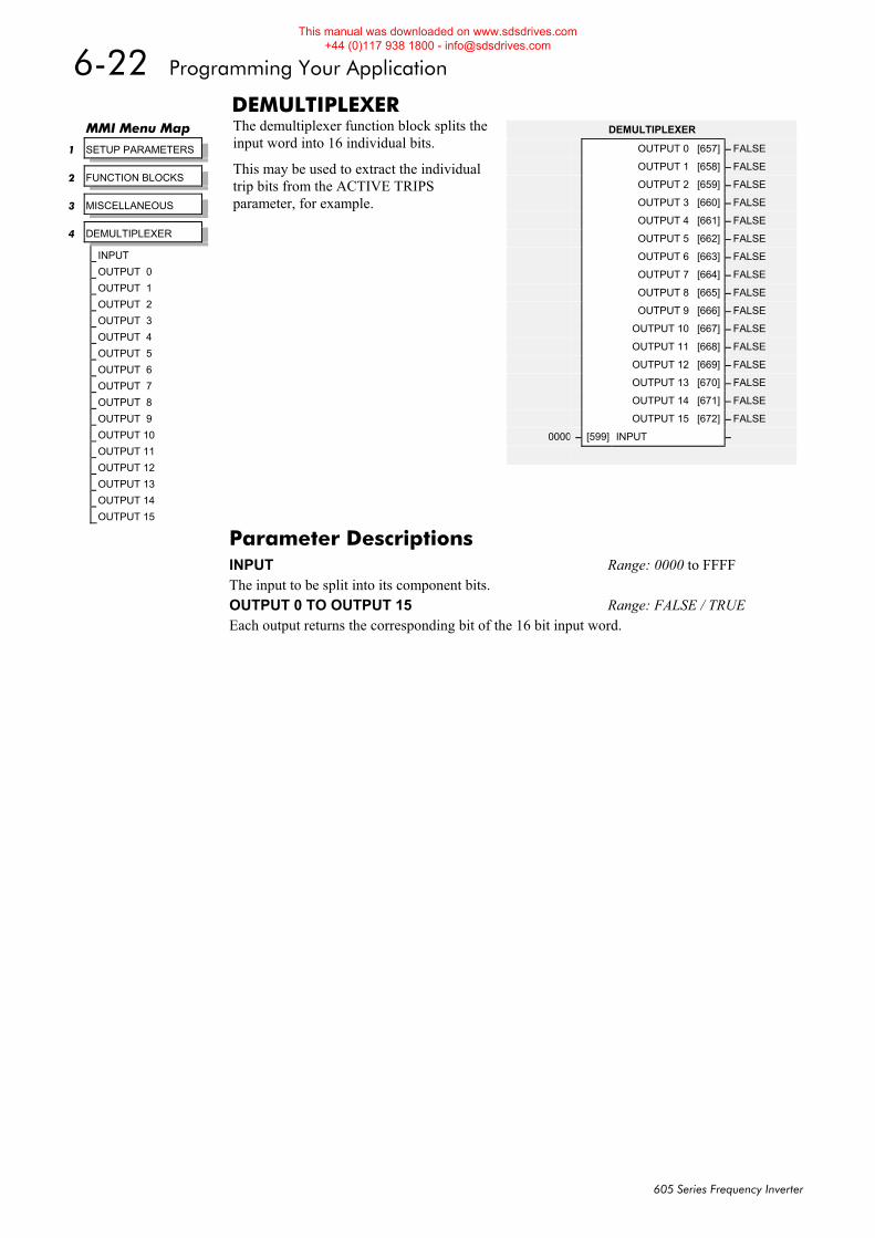
6-22 Programming Your Application
605 Series Frequency Inverter
DEMULTIPLEXER The demultiplexer function block splits the input word into 16 individual bits.
This may be used to extract the individual trip bits from the ACTIVE TRIPS parameter, for example.
MMI Menu Map
1 SETUP PARAMETERS
2 FUNCTION BLOCKS
3 MISCELLANEOUS
4 DEMULTIPLEXER
INPUT
OUTPUT 0
OUTPUT 1
OUTPUT 2
OUTPUT 3
OUTPUT 4
OUTPUT 5
OUTPUT 6
OUTPUT 7
OUTPUT 8
OUTPUT 9
OUTPUT 10
OUTPUT 11
OUTPUT 12
OUTPUT 13
OUTPUT 14
OUTPUT 15
DEMULTIPLEXER
OUTPUT 0 [657] – FALSE
OUTPUT 1 [658] – FALSE
OUTPUT 2 [659] – FALSE
OUTPUT 3 [660] – FALSE
OUTPUT 4 [661] – FALSE
OUTPUT 5 [662] – FALSE
OUTPUT 6 [663] – FALSE
OUTPUT 7 [664] – FALSE
OUTPUT 8 [665] – FALSE
OUTPUT 9 [666] – FALSE
OUTPUT 10 [667] – FALSE
OUTPUT 11 [668] – FALSE
OUTPUT 12 [669] – FALSE
OUTPUT 13 [670] – FALSE
OUTPUT 14 [671] – FALSE
OUTPUT 15 [672] – FALSE
0000 – [599] INPUT –
Parameter Descriptions INPUT Range: 0000 to FFFF The input to be split into its component bits. OUTPUT 0 TO OUTPUT 15 Range: FALSE / TRUE Each output returns the corresponding bit of the 16 bit input word.
This manual was downloaded on www.sdsdrives.com +44 (0)117 938 1800 - [email protected]
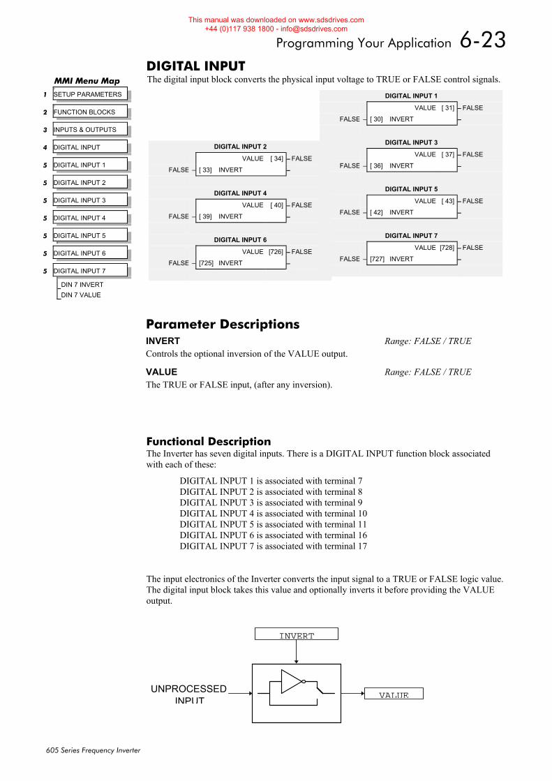
Programming Your Application 6-23
605 Series Frequency Inverter
DIGITAL INPUT The digital input block converts the physical input voltage to TRUE or FALSE control signals.
Functional Description The Inverter has seven digital inputs. There is a DIGITAL INPUT function block associated with each of these:
DIGITAL INPUT 1 is associated with terminal 7 DIGITAL INPUT 2 is associated with terminal 8 DIGITAL INPUT 3 is associated with terminal 9 DIGITAL INPUT 4 is associated with terminal 10 DIGITAL INPUT 5 is associated with terminal 11 DIGITAL INPUT 6 is associated with terminal 16 DIGITAL INPUT 7 is associated with terminal 17
The input electronics of the Inverter converts the input signal to a TRUE or FALSE logic value. The digital input block takes this value and optionally inverts it before providing the VALUE output.
MMI Menu Map 7
1 SETUP PARAMETERS
7
2 FUNCTION BLOCKS
3 INPUTS & OUTPUTS
4 DIGITAL INPUT
5 DIGITAL INPUT 1
5 DIGITAL INPUT 2
5 DIGITAL INPUT 3
5 DIGITAL INPUT 4
5 DIGITAL INPUT 5
5 DIGITAL INPUT 6
5 DIGITAL INPUT 7
DIN 7 INVERT
DIN 7 VALUE
DIGITAL INPUT 1
VALUE [ 31] – FALSE
FALSE – [ 30] INVERT –
DIGITAL INPUT 3
VALUE [ 37] – FALSE
FALSE – [ 36] INVERT –
DIGITAL INPUT 5
VALUE [ 43] – FALSE
FALSE – [ 42] INVERT –
DIGITAL INPUT 7
VALUE [728] – FALSE
FALSE – [727] INVERT –
DIGITAL INPUT 2
VALUE [ 34] – FALSE
FALSE – [ 33] INVERT –
DIGITAL INPUT 4
VALUE [ 40] – FALSE
FALSE – [ 39] INVERT –
DIGITAL INPUT 6
VALUE [726] – FALSE
FALSE – [725] INVERT –
Parameter Descriptions INVERT Range: FALSE / TRUE Controls the optional inversion of the VALUE output.
VALUE Range: FALSE / TRUE The TRUE or FALSE input, (after any inversion).
INPUT VALUE
INVERT
UNPROCESSED
This manual was downloaded on www.sdsdrives.com +44 (0)117 938 1800 - [email protected]
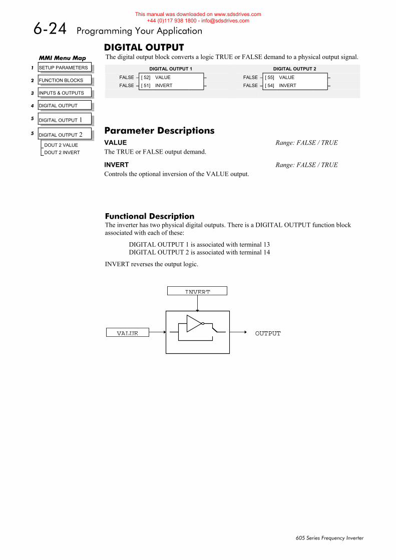
6-24 Programming Your Application
605 Series Frequency Inverter
DIGITAL OUTPUT The digital output block converts a logic TRUE or FALSE demand to a physical output signal.
Functional Description The inverter has two physical digital outputs. There is a DIGITAL OUTPUT function block associated with each of these:
DIGITAL OUTPUT 1 is associated with terminal 13 DIGITAL OUTPUT 2 is associated with terminal 14
INVERT reverses the output logic.
MMI Menu Map
1 SETUP PARAMETERS
2 FUNCTION BLOCKS
3 INPUTS & OUTPUTS
4 DIGITAL OUTPUT
5 DIGITAL OUTPUT 1
5 DIGITAL OUTPUT 2
DOUT 2 VALUE
DOUT 2 INVERT
Parameter Descriptions VALUE Range: FALSE / TRUE The TRUE or FALSE output demand.
INVERT Range: FALSE / TRUE Controls the optional inversion of the VALUE output.
DIGITAL OUTPUT 2
FALSE – [ 55] VALUE –
FALSE – [ 54] INVERT –
DIGITAL OUTPUT 1
FALSE – [ 52] VALUE –
FALSE – [ 51] INVERT –
OUTPUT
INVERT
VALUE
This manual was downloaded on www.sdsdrives.com +44 (0)117 938 1800 - [email protected]
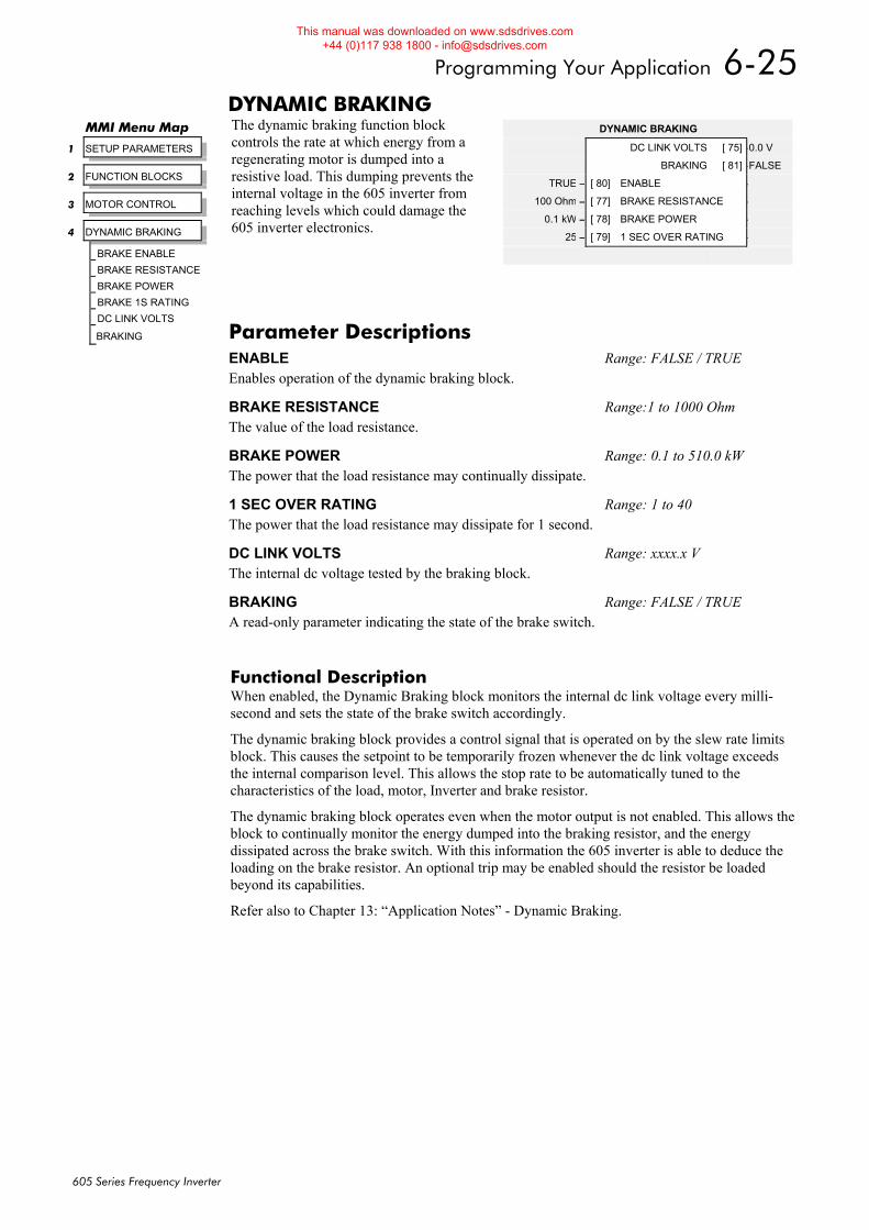
Programming Your Application 6-25
605 Series Frequency Inverter
DYNAMIC BRAKING The dynamic braking function block controls the rate at which energy from a regenerating motor is dumped into a resistive load. This dumping prevents the internal voltage in the 605 inverter from reaching levels which could damage the 605 inverter electronics.
Functional Description When enabled, the Dynamic Braking block monitors the internal dc link voltage every milli-second and sets the state of the brake switch accordingly.
The dynamic braking block provides a control signal that is operated on by the slew rate limits block. This causes the setpoint to be temporarily frozen whenever the dc link voltage exceeds the internal comparison level. This allows the stop rate to be automatically tuned to the characteristics of the load, motor, Inverter and brake resistor.
The dynamic braking block operates even when the motor output is not enabled. This allows the block to continually monitor the energy dumped into the braking resistor, and the energy dissipated across the brake switch. With this information the 605 inverter is able to deduce the loading on the brake resistor. An optional trip may be enabled should the resistor be loaded beyond its capabilities.
Refer also to Chapter 13: “Application Notes” - Dynamic Braking.
MMI Menu Map
1 SETUP PARAMETERS
2 FUNCTION BLOCKS
3 MOTOR CONTROL
4 DYNAMIC BRAKING
BRAKE ENABLE
BRAKE RESISTANCE
BRAKE POWER
BRAKE 1S RATING
DC LINK VOLTS
BRAKING
DYNAMIC BRAKING
DC LINK VOLTS [ 75] –0.0 V
BRAKING [ 81] –FALSE
TRUE – [ 80] ENABLE –
100 Ohm – [ 77] BRAKE RESISTANCE –
0.1 kW – [ 78] BRAKE POWER –
25 – [ 79] 1 SEC OVER RATING –
Parameter Descriptions ENABLE Range: FALSE / TRUE Enables operation of the dynamic braking block.
BRAKE RESISTANCE Range:1 to 1000 Ohm The value of the load resistance.
BRAKE POWER Range: 0.1 to 510.0 kW The power that the load resistance may continually dissipate.
1 SEC OVER RATING Range: 1 to 40 The power that the load resistance may dissipate for 1 second.
DC LINK VOLTS Range: xxxx.x V The internal dc voltage tested by the braking block.
BRAKING Range: FALSE / TRUE A read-only parameter indicating the state of the brake switch.
This manual was downloaded on www.sdsdrives.com +44 (0)117 938 1800 - [email protected]
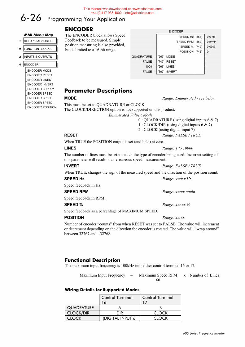
6-26 Programming Your Application
605 Series Frequency Inverter
ENCODER The ENCODER block allows Speed Feedback to be measured. Simple position measuring is also provided, but is limited to a 16-bit range.
Functional Description The maximum input frequency is 100kHz into either control terminal 16 or 17. Maximum Input Frequency = Maximum Speed RPM x Number of Lines 60 Wiring Details for Supported Modes
Control Terminal 16
Control Terminal 17
QUADRATURE A B CLOCK/DIR DIR CLOCK CLOCK (DIGITAL INPUT 6) CLOCK
MMI Menu Map
1 SETUP/DIAGNOSTIC
2 FUNCTION BLOCKS
3 INPUTS & OUTPUTS
4 ENCODER
ENCODER MODE
ENCODER RESET
ENCODER LINES
ENCODER INVERT
ENCODER SUPPLY
ENCODER SPEED
ENCODER SPEED
ENCODER SPEED
ENCODER POSITION
ENCODER
SPEED Hz [568] – 0.0 Hz
SPEED RPM [569] – 0 n/min
SPEED % [749] – 0.00%
POSITION [748] – 0
QUADRATURE – [565] MODE –
FALSE – [747] RESET –
1000 – [566] LINES –
FALSE – [567] INVERT –
Parameter Descriptions MODE Range: Enumerated - see below
This must be set to QUADRATURE or CLOCK. The CLOCK/DIRECTION option is not supported on this product.
Enumerated Value : Mode 0 : QUADRATURE (using digital inputs 6 & 7) 1 : CLOCK/DIR (using digital inputs 6 & 7) 2 : CLOCK (using digital input 7)
RESET Range: FALSE / TRUE When TRUE the POSITION output is set (and held) at zero. LINES Range: 1 to 10000 The number of lines must be set to match the type of encoder being used. Incorrect setting of this parameter will result in an erroneous speed measurement. INVERT Range: FALSE / TRUE When TRUE, changes the sign of the measured speed and the direction of the position count. SPEED Hz Range: xxxx.x Hz Speed feedback in Hz. SPEED RPM Range: xxxxx n/min Speed feedback in RPM. SPEED % Range: xxx.xx % Speed feedback as a percentage of MAXIMUM SPEED. POSITION Range: xxxxx Number of encoder “counts” from when RESET was set to FALSE. The value will increment or decrement depending on the direction the encoder is rotated. The value will “wrap around” between 32767 and -32768.
This manual was downloaded on www.sdsdrives.com +44 (0)117 938 1800 - [email protected]
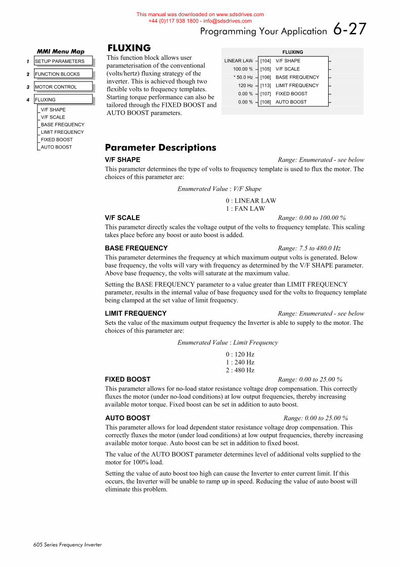
Programming Your Application 6-27
605 Series Frequency Inverter
FLUXING This function block allows user parameterisation of the conventional (volts/hertz) fluxing strategy of the inverter. This is achieved though two flexible volts to frequency templates. Starting torque performance can also be tailored through the FIXED BOOST and AUTO BOOST parameters.
FLUXING
LINEAR LAW – [104] V/F SHAPE –
100.00 % – [105] V/F SCALE –
* 50.0 Hz – [106] BASE FREQUENCY –
120 Hz – [113] LIMIT FREQUENCY –
0.00 % – [107] FIXED BOOST –
0.00 % – [108] AUTO BOOST –
MMI Menu Map
1 SETUP PARAMETERS
2 FUNCTION BLOCKS
3 MOTOR CONTROL
4 FLUXING
V/F SHAPE
V/F SCALE
BASE FREQUENCY
LIMIT FREQUENCY
FIXED BOOST
AUTO BOOST Parameter Descriptions V/F SHAPE Range: Enumerated - see belowThis parameter determines the type of volts to frequency template is used to flux the motor. The choices of this parameter are:
Enumerated Value : V/F Shape
0 : LINEAR LAW 1 : FAN LAW
V/F SCALE Range: 0.00 to 100.00 % This parameter directly scales the voltage output of the volts to frequency template. This scaling takes place before any boost or auto boost is added.
BASE FREQUENCY Range: 7.5 to 480.0 Hz This parameter determines the frequency at which maximum output volts is generated. Below base frequency, the volts will vary with frequency as determined by the V/F SHAPE parameter. Above base frequency, the volts will saturate at the maximum value.
Setting the BASE FREQUENCY parameter to a value greater than LIMIT FREQUENCY parameter, results in the internal value of base frequency used for the volts to frequency template being clamped at the set value of limit frequency.
LIMIT FREQUENCY Range: Enumerated - see belowSets the value of the maximum output frequency the Inverter is able to supply to the motor. The choices of this parameter are:
Enumerated Value : Limit Frequency
0 : 120 Hz 1 : 240 Hz 2 : 480 Hz
FIXED BOOST Range: 0.00 to 25.00 % This parameter allows for no-load stator resistance voltage drop compensation. This correctly fluxes the motor (under no-load conditions) at low output frequencies, thereby increasing available motor torque. Fixed boost can be set in addition to auto boost.
AUTO BOOST Range: 0.00 to 25.00 % This parameter allows for load dependent stator resistance voltage drop compensation. This correctly fluxes the motor (under load conditions) at low output frequencies, thereby increasing available motor torque. Auto boost can be set in addition to fixed boost.
The value of the AUTO BOOST parameter determines level of additional volts supplied to the motor for 100% load.
Setting the value of auto boost too high can cause the Inverter to enter current limit. If this occurs, the Inverter will be unable to ramp up in speed. Reducing the value of auto boost will eliminate this problem.
This manual was downloaded on www.sdsdrives.com +44 (0)117 938 1800 - [email protected]
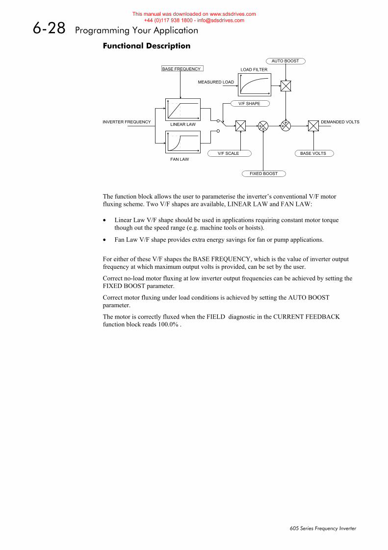
6-28 Programming Your Application
605 Series Frequency Inverter
Functional Description
The function block allows the user to parameterise the inverter’s conventional V/F motor fluxing scheme. Two V/F shapes are available, LINEAR LAW and FAN LAW:
• Linear Law V/F shape should be used in applications requiring constant motor torque though out the speed range (e.g. machine tools or hoists).
• Fan Law V/F shape provides extra energy savings for fan or pump applications.
For either of these V/F shapes the BASE FREQUENCY, which is the value of inverter output frequency at which maximum output volts is provided, can be set by the user.
Correct no-load motor fluxing at low inverter output frequencies can be achieved by setting the FIXED BOOST parameter.
Correct motor fluxing under load conditions is achieved by setting the AUTO BOOST parameter.
The motor is correctly fluxed when the FIELD diagnostic in the CURRENT FEEDBACK function block reads 100.0% .
LINEAR LAW
FAN LAW
LOAD FILTER
DEMANDED VOLTSINVERTER FREQUENCY
MEASURED LOAD
V/F SHAPE
BASE FREQUENCY
AUTO BOOST
FIXED BOOST
V/F SCALE BASE VOLTS
This manual was downloaded on www.sdsdrives.com +44 (0)117 938 1800 - [email protected]
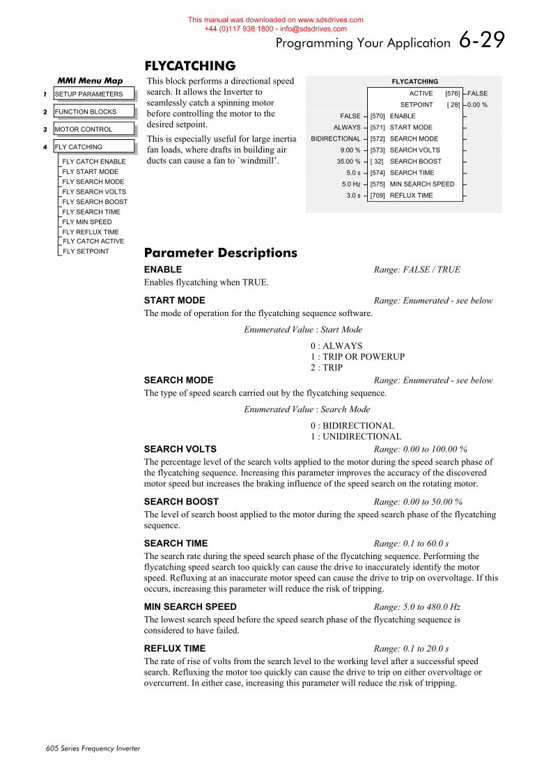
Programming Your Application 6-29
605 Series Frequency Inverter
FLYCATCHING This block performs a directional speed search. It allows the Inverter to seamlessly catch a spinning motor before controlling the motor to the desired setpoint. This is especially useful for large inertia fan loads, where drafts in building air ducts can cause a fan to `windmill’.
MMI Menu Map
1 SETUP PARAMETERS
2 FUNCTION BLOCKS
3 MOTOR CONTROL
4 FLY CATCHING
FLY CATCH ENABLE FLY START MODE FLY SEARCH MODE FLY SEARCH VOLTS FLY SEARCH BOOST FLY SEARCH TIME FLY MIN SPEED FLY REFLUX TIME FLY CATCH ACTIVE
FLY SETPOINT
FLYCATCHING
ACTIVE [576] –FALSE
SETPOINT [ 28] –0.00 %
FALSE – [570] ENABLE –
ALWAYS – [571] START MODE –
BIDIRECTIONAL – [572] SEARCH MODE –
9.00 % – [573] SEARCH VOLTS –
35.00 % – [ 32] SEARCH BOOST –
5.0 s – [574] SEARCH TIME –
5.0 Hz – [575] MIN SEARCH SPEED –
3.0 s – [709] REFLUX TIME –
Parameter Descriptions ENABLE Range: FALSE / TRUE Enables flycatching when TRUE.
START MODE Range: Enumerated - see below The mode of operation for the flycatching sequence software.
Enumerated Value : Start Mode
0 : ALWAYS 1 : TRIP OR POWERUP 2 : TRIP
SEARCH MODE Range: Enumerated - see below The type of speed search carried out by the flycatching sequence.
Enumerated Value : Search Mode
0 : BIDIRECTIONAL 1 : UNIDIRECTIONAL
SEARCH VOLTS Range: 0.00 to 100.00 % The percentage level of the search volts applied to the motor during the speed search phase of the flycatching sequence. Increasing this parameter improves the accuracy of the discovered motor speed but increases the braking influence of the speed search on the rotating motor.
SEARCH BOOST Range: 0.00 to 50.00 % The level of search boost applied to the motor during the speed search phase of the flycatching sequence.
SEARCH TIME Range: 0.1 to 60.0 s The search rate during the speed search phase of the flycatching sequence. Performing the flycatching speed search too quickly can cause the drive to inaccurately identify the motor speed. Refluxing at an inaccurate motor speed can cause the drive to trip on overvoltage. If this occurs, increasing this parameter will reduce the risk of tripping.
MIN SEARCH SPEED Range: 5.0 to 480.0 Hz The lowest search speed before the speed search phase of the flycatching sequence is considered to have failed.
REFLUX TIME Range: 0.1 to 20.0 s The rate of rise of volts from the search level to the working level after a successful speed search. Refluxing the motor too quickly can cause the drive to trip on either overvoltage or overcurrent. In either case, increasing this parameter will reduce the risk of tripping.
This manual was downloaded on www.sdsdrives.com +44 (0)117 938 1800 - [email protected]
6-30 Programming Your Application
605 Series Frequency Inverter
Functional Description The flycatching function enables the drive to be restarted smoothly into a spinning motor. It applies small search voltages to the motor whilst ramping the Inverter frequency from maximum speed to zero. When the motor load goes from motoring to regenerating, the speed search has succeeded and is terminated. If the search frequency falls below the minimum search speed, the speed search has failed and the Inverter will ramp to the speed setpoint from zero.
The flycatching sequence can be triggered by different starting conditions:
ALWAYS: All starts (after controlled or uncontrolled stop, or after a power-up) TRIP or POWER-UP: After uncontrolled stop, i.e. trip or coast, or after a power-up TRIP: After uncontrolled stop, i.e. trip or coast
The type of speed sequence may be Bidirectional or Unidirectional:
Bidirectional Initially, the search is performed in the direction of the speed setpoint. If the drive fails to identify the motor speed in this direction, a second speed search is performed in the reverse direction.
Unidirectional The search is performed only in the direction of the speed setpoint.
ACTIVE Range: FALSE / TRUE A diagnostic output indicating whether the flycatching sequence is active.
SETPOINT Range xxx.xx % This diagnostic output is the setpoint caught at the end of a successful flycatching sequence.
This manual was downloaded on www.sdsdrives.com +44 (0)117 938 1800 - [email protected]
Programming Your Application 6-31
605 Series Frequency Inverter
I/O TRIPS This function block is designed to operate in conjunction with the Analog and Digital Input function blocks to trip the inverter on a loss of setpoint input or safety control input.
Functional Description The I/O TRIPS function block allows trips to be generated by signals on the input terminals of the inverter. Refer to Chapter 7 for a description of the trips supported by the 605 inverter.
MMI Menu Map
1 SETUP PARAMETERS
2 FUNCTION BLOCKS
3 TRIPS
4 I/O TRIPS
EXTERNAL TRIP
INPUT 1 BREAK
INPUT 2 BREAK
I/O TRIPS
FALSE – [234] EXTERNAL TRIP –
FALSE – [235] INPUT 1 BREAK –
FALSE – [236] INPUT 2 BREAK –
Parameter Descriptions EXTERNAL TRIP Range: FALSE / TRUE A general purpose signal designed to be internally wired to a digital input block. When this signal goes TRUE this causes an EXTERNAL TRIP to occur, (unless this trip is disabled within the TRIPS area).
This parameter is not saved in the inverter’s non-volatile memory and thus is reset to the default setting at power-up.
INPUT 1 BREAK Range: FALSE / TRUE A general purpose signal designed to be internally wired to the function block ANALOG INPUT 1, BREAK parameter. When this signal goes TRUE this causes an INPUT 1 BREAK trip to occur, (unless this trip is disabled within the TRIPS STATUS function block, see DISABLED TRIPS.
This parameter is not saved in the inverter’s non-volatile memory and thus is reset to the default setting at power-up.
INPUT 2 BREAK Range: FALSE / TRUE A general purpose signal designed to be internally wired to the function block ANALOG INPUT 2, BREAK parameter. When this signal goes TRUE this causes an INPUT 2 BREAK trip to occur (unless this trip is disabled within the TRIPS STATUS function block, see DISABLED TRIPS.
This parameter is not saved in the inverter’s non-volatile memory and thus is reset to the default setting at power-up.
This manual was downloaded on www.sdsdrives.com +44 (0)117 938 1800 - [email protected]
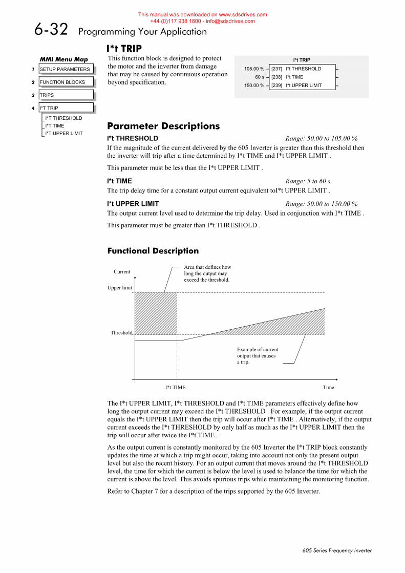
6-32 Programming Your Application
605 Series Frequency Inverter
I*t TRIP This function block is designed to protect the motor and the inverter from damage that may be caused by continuous operation beyond specification.
Functional Description
The I*t UPPER LIMIT, I*t THRESHOLD and I*t TIME parameters effectively define how long the output current may exceed the I*t THRESHOLD . For example, if the output current equals the I*t UPPER LIMIT then the trip will occur after I*t TIME . Alternatively, if the output current exceeds the I*t THRESHOLD by only half as much as the I*t UPPER LIMIT then the trip will occur after twice the I*t TIME .
As the output current is constantly monitored by the 605 Inverter the I*t TRIP block constantly updates the time at which a trip might occur, taking into account not only the present output level but also the recent history. For an output current that moves around the I*t THRESHOLD level, the time for which the current is below the level is used to balance the time for which the current is above the level. This avoids spurious trips while maintaining the monitoring function.
Refer to Chapter 7 for a description of the trips supported by the 605 Inverter.
MMI Menu Map
1 SETUP PARAMETERS
2 FUNCTION BLOCKS
3 TRIPS
4 I*T TRIP
I*T THRESHOLD
I*T TIME
I*T UPPER LIMIT
I*t TRIP
105.00 % – [237] I*t THRESHOLD –
60 s – [238] I*t TIME –
150.00 % – [239] I*t UPPER LIMIT –
Parameter Descriptions I*t THRESHOLD Range: 50.00 to 105.00 % If the magnitude of the current delivered by the 605 Inverter is greater than this threshold then the inverter will trip after a time determined by I*t TIME and I*t UPPER LIMIT .
This parameter must be less than the I*t UPPER LIMIT .
I*t TIME Range: 5 to 60 s The trip delay time for a constant output current equivalent toI*t UPPER LIMIT .
I*t UPPER LIMIT Range: 50.00 to 150.00 % The output current level used to determine the trip delay. Used in conjunction with I*t TIME .
This parameter must be greater than I*t THRESHOLD .
Time
CurrentArea that defines howlong the output mayexceed the threshold.
Example of currentoutput that causesa trip.
Upper limit
Threshold
I*t TIME
This manual was downloaded on www.sdsdrives.com +44 (0)117 938 1800 - [email protected]
Programming Your Application 6-33
605 Series Frequency Inverter
INJ BRAKING The injection braking block provides a method of stopping spinning induction motors without returning the kinetic energy of the motor and load back in to the dc link of the inverter. This is achieved by running the motor highly inefficiently so that all the energy stored in the load is dissipated in the motor. Thus, high inertia loads can be stopped without the need for an external dynamic braking resistor.
MMI Menu Map
1 SETUP PARAMETERS
2 FUNCTION BLOCKS
3 MOTOR CONTROL
4 INJ BRAKING
INJ DEFLUX TIME
INJ FREQUENCY
INJ I-LIM LEVEL
INJ DC PULSE
INJ FINAL DC
INJ DC LEVEL
INJ TIMEOUT
INJ BASE VOLTS
INJ ACTIVE
INJ BRAKING
ACTIVE [583] – FALSE
0.5 s – [710] DEFLUX TIME –
9.0 Hz – [577] FREQUENCY –
100.00 % – [578] I-LIM LEVEL –
2.0 s – [579] DC PULSE –
1.0 s – [580] FINAL DC PULSE –
3.00 % – [581] DC LEVEL –
600.0 s – [582] TIMEOUT
100.00 % – [739] BASE VOLTS –
Parameter Descriptions DEFLUX TIME Range: 0.1 to 20.0 s Determines the time in which the inverter defluxes the motor prior injection braking.
FREQUENCY Range: 1.0 to 480.0 Hz Determines the maximum frequency applied to the motor for the low frequency injection braking mode. It is also clamped internally so as never to exceed 50% of base speed value.
I-LIM LEVEL Range: 50.00 to 150.00 % Determines the level of motor current flowing during low frequency injection braking.
DC PULSE Range: 0.0 to 100.0 s Determines the duration of the dc pulse applied to the motor when injection braking is required for motor speeds below 20% of base speed. The actual dc pulse time applied to the motor is dependent on the ratio of initial motor speed to 20% of base speed.
FINAL DC PULSE Range: 0.0 to 10.0 s Determines the duration of the final dc holding pulse applied to the motor after either low frequency injection braking or timed dc pulse.
DC LEVEL Range: 0.00 to 25.00 % Determines the level of dc pulse applied to the motor during either the timed or final dc pulse.
TIMEOUT Range: 0.0 to 600.0 s Determines the maximum amount of time the sequence is allowed to remain in the low frequency injection braking state.
BASE VOLTS Range: 0.00 to 115.47 % Determines the maximum volts at base speed applied to the motor during injection braking.
ACTIVE Range: FALSE / TRUE Indicates the state of the inverter. TRUE when injection braking.
This manual was downloaded on www.sdsdrives.com +44 (0)117 938 1800 - [email protected]
6-34 Programming Your Application
605 Series Frequency Inverter
JOG This block holds all the parameters that concern the Jog functionality on the inverter.
Functional Description The JOG function block is used to configure the action of the 605 inverter when used in jog mode. The various operating modes are described in more detail in Chapter 4: “Operating the Inverter” - The Start/Stop Mode Explained.
MMI Menu Map
1 SETUP PARAMETERS
2 FUNCTION BLOCKS
3 SEQ & REF
4 JOG
JOG SETPOINT
JOG ACCEL RATE
JOG DECEL RATE
JOG
10.00 % – [246] SETPOINT –
1.0 s – [261] ACCEL RATE –
1.0 s – [262] DECEL RATE –
Parameter Descriptions SETPOINT Range: 0.00 to 100.00 % (h) The setpoint is the target reference that the inverter will ramp to. Direction is taken from the current mode, (LOCAL or REMOTE).
ACCEL RATE Range: 0.0 to 600.0 s The jog mode acceleration rate.
DECEL RATE Range: 0.0 to 600.0 s The jog mode deceleration rate.
This manual was downloaded on www.sdsdrives.com +44 (0)117 938 1800 - [email protected]
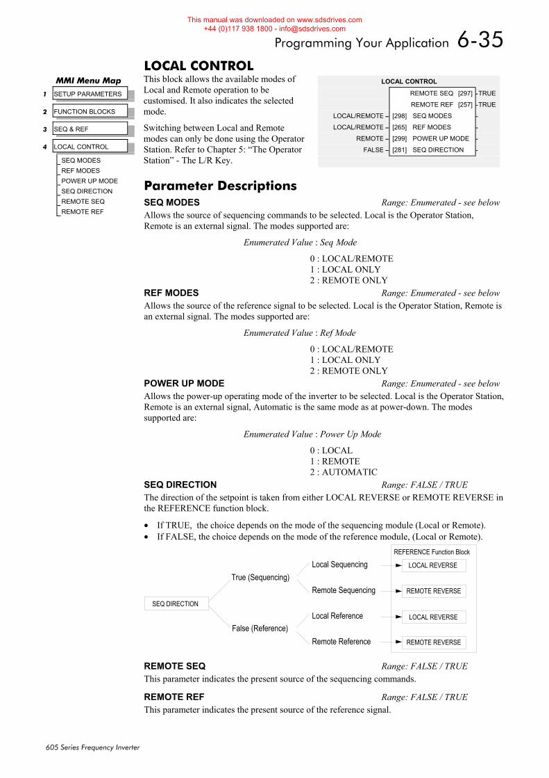
Programming Your Application 6-35
605 Series Frequency Inverter
LOCAL CONTROL This block allows the available modes of Local and Remote operation to be customised. It also indicates the selected mode.
Switching between Local and Remote modes can only be done using the Operator Station. Refer to Chapter 5: “The Operator Station” - The L/R Key.
MMI Menu Map
1 SETUP PARAMETERS
2 FUNCTION BLOCKS
3 SEQ & REF
4 LOCAL CONTROL
SEQ MODES
REF MODES
POWER UP MODE
SEQ DIRECTION
REMOTE SEQ
REMOTE REF
LOCAL CONTROL
REMOTE SEQ [297] –TRUE
REMOTE REF [257] –TRUE
LOCAL/REMOTE – [298] SEQ MODES –
LOCAL/REMOTE – [265] REF MODES –
REMOTE – [299] POWER UP MODE –
FALSE – [281] SEQ DIRECTION –
Parameter Descriptions SEQ MODES Range: Enumerated - see belowAllows the source of sequencing commands to be selected. Local is the Operator Station, Remote is an external signal. The modes supported are:
Enumerated Value : Seq Mode
0 : LOCAL/REMOTE 1 : LOCAL ONLY 2 : REMOTE ONLY
REF MODES Range: Enumerated - see belowAllows the source of the reference signal to be selected. Local is the Operator Station, Remote is an external signal. The modes supported are:
Enumerated Value : Ref Mode
0 : LOCAL/REMOTE 1 : LOCAL ONLY 2 : REMOTE ONLY
POWER UP MODE Range: Enumerated - see belowAllows the power-up operating mode of the inverter to be selected. Local is the Operator Station,Remote is an external signal, Automatic is the same mode as at power-down. The modes supported are:
Enumerated Value : Power Up Mode
0 : LOCAL 1 : REMOTE 2 : AUTOMATIC
SEQ DIRECTION Range: FALSE / TRUE The direction of the setpoint is taken from either LOCAL REVERSE or REMOTE REVERSE in the REFERENCE function block.
• If TRUE, the choice depends on the mode of the sequencing module (Local or Remote). • If FALSE, the choice depends on the mode of the reference module, (Local or Remote).
LOCAL REVERSE
REMOTE REVERSE
LOCAL REVERSE
REMOTE REVERSE
REFERENCE Function Block
SEQ DIRECTION
True (Sequencing)
False (Reference)
Local Sequencing
Remote Sequencing
Local Reference
Remote Reference
REMOTE SEQ Range: FALSE / TRUE This parameter indicates the present source of the sequencing commands.
REMOTE REF Range: FALSE / TRUE This parameter indicates the present source of the reference signal.
This manual was downloaded on www.sdsdrives.com +44 (0)117 938 1800 - [email protected]
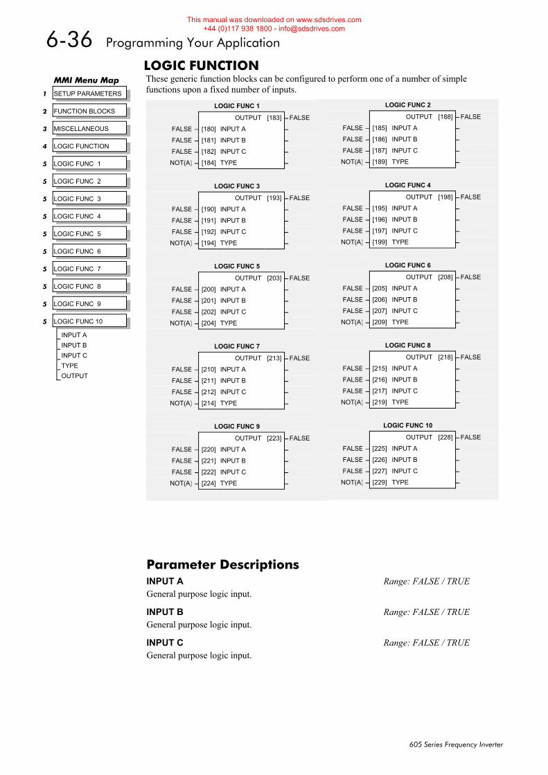
6-36 Programming Your Application
605 Series Frequency Inverter
LOGIC FUNCTION These generic function blocks can be configured to perform one of a number of simple functions upon a fixed number of inputs.
MMI Menu Map
1 SETUP PARAMETERS
2 FUNCTION BLOCKS
3 MISCELLANEOUS
4 LOGIC FUNCTION
5 LOGIC FUNC 1
5 LOGIC FUNC 2
5 LOGIC FUNC 3
5 LOGIC FUNC 4
5 LOGIC FUNC 5
5 LOGIC FUNC 6
5 LOGIC FUNC 7
5 LOGIC FUNC 8
5 LOGIC FUNC 9
5 LOGIC FUNC 10
INPUT A
INPUT B
INPUT C
TYPE
OUTPUT
LOGIC FUNC 2
OUTPUT [188] – FALSE
FALSE – [185] INPUT A –
FALSE – [186] INPUT B –
FALSE – [187] INPUT C –
NOT(A) – [189] TYPE –
LOGIC FUNC 4
OUTPUT [198] – FALSE
FALSE – [195] INPUT A –
FALSE – [196] INPUT B –
FALSE – [197] INPUT C –
NOT(A) – [199] TYPE –
LOGIC FUNC 6
OUTPUT [208] – FALSE
FALSE – [205] INPUT A –
FALSE – [206] INPUT B –
FALSE – [207] INPUT C –
NOT(A) – [209] TYPE –
LOGIC FUNC 8
OUTPUT [218] – FALSE
FALSE – [215] INPUT A –
FALSE – [216] INPUT B –
FALSE – [217] INPUT C –
NOT(A) – [219] TYPE –
LOGIC FUNC 10
OUTPUT [228] – FALSE
FALSE – [225] INPUT A –
FALSE – [226] INPUT B –
FALSE – [227] INPUT C –
NOT(A) – [229] TYPE –
LOGIC FUNC 1
OUTPUT [183] – FALSE
FALSE – [180] INPUT A –
FALSE – [181] INPUT B –
FALSE – [182] INPUT C –
NOT(A) – [184] TYPE –
LOGIC FUNC 3
OUTPUT [193] – FALSE
FALSE – [190] INPUT A –
FALSE – [191] INPUT B –
FALSE – [192] INPUT C –
NOT(A) – [194] TYPE –
LOGIC FUNC 5
OUTPUT [203] – FALSE
FALSE – [200] INPUT A –
FALSE – [201] INPUT B –
FALSE – [202] INPUT C –
NOT(A) – [204] TYPE –
LOGIC FUNC 7
OUTPUT [213] – FALSE
FALSE – [210] INPUT A –
FALSE – [211] INPUT B –
FALSE – [212] INPUT C –
NOT(A) – [214] TYPE –
LOGIC FUNC 9
OUTPUT [223] – FALSE
FALSE – [220] INPUT A –
FALSE – [221] INPUT B –
FALSE – [222] INPUT C –
NOT(A) – [224] TYPE –
Parameter Descriptions INPUT A Range: FALSE / TRUE General purpose logic input.
INPUT B Range: FALSE / TRUE General purpose logic input.
INPUT C Range: FALSE / TRUE General purpose logic input.
This manual was downloaded on www.sdsdrives.com +44 (0)117 938 1800 - [email protected]
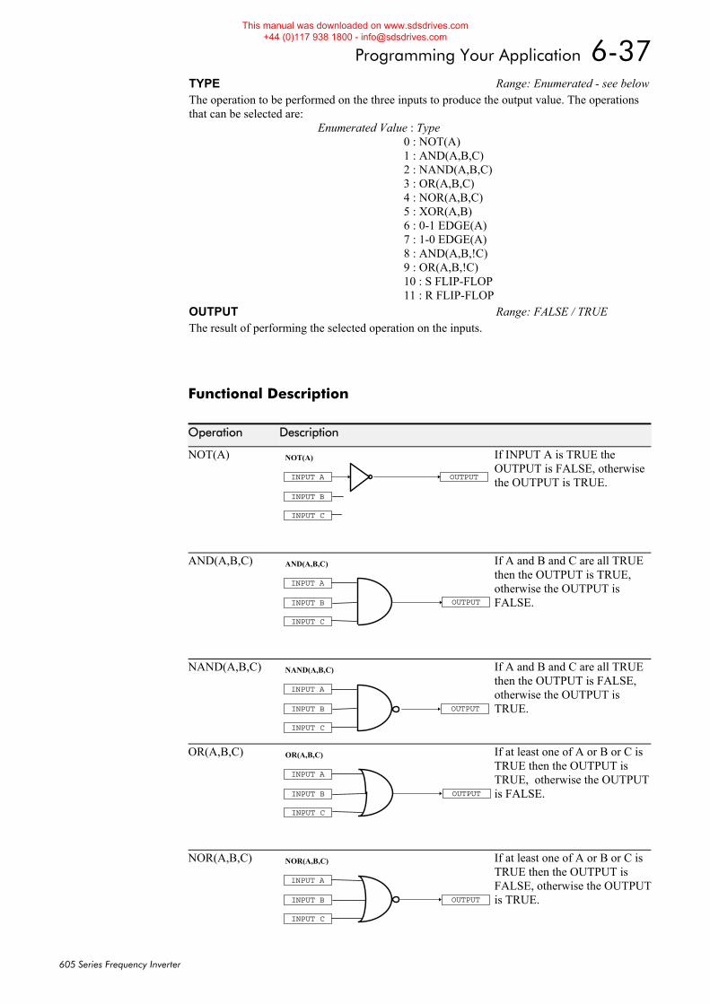
Programming Your Application 6-37
605 Series Frequency Inverter
Functional Description
Operation Description
NOT(A)
OUTPUTINPUT A
INPUT B
INPUT C
NOT(A)
If INPUT A is TRUE the OUTPUT is FALSE, otherwise the OUTPUT is TRUE.
AND(A,B,C)
OUTPUT
INPUT A
INPUT B
INPUT C
AND(A,B,C)
If A and B and C are all TRUE then the OUTPUT is TRUE, otherwise the OUTPUT is FALSE.
NAND(A,B,C)
OUTPUT
INPUT A
INPUT B
INPUT C
NAND(A,B,C) If A and B and C are all TRUE then the OUTPUT is FALSE, otherwise the OUTPUT is TRUE.
OR(A,B,C)
OUTPUT
INPUT A
INPUT B
INPUT C
OR(A,B,C)
If at least one of A or B or C is TRUE then the OUTPUT is TRUE, otherwise the OUTPUT is FALSE.
NOR(A,B,C)
OUTPUT
INPUT A
INPUT B
INPUT C
NOR(A,B,C) If at least one of A or B or C is TRUE then the OUTPUT is FALSE, otherwise the OUTPUT is TRUE.
TYPE Range: Enumerated - see belowThe operation to be performed on the three inputs to produce the output value. The operations that can be selected are:
Enumerated Value : Type 0 : NOT(A) 1 : AND(A,B,C) 2 : NAND(A,B,C) 3 : OR(A,B,C) 4 : NOR(A,B,C) 5 : XOR(A,B) 6 : 0-1 EDGE(A) 7 : 1-0 EDGE(A) 8 : AND(A,B,!C) 9 : OR(A,B,!C) 10 : S FLIP-FLOP 11 : R FLIP-FLOP
OUTPUT Range: FALSE / TRUE The result of performing the selected operation on the inputs.
This manual was downloaded on www.sdsdrives.com +44 (0)117 938 1800 - [email protected]
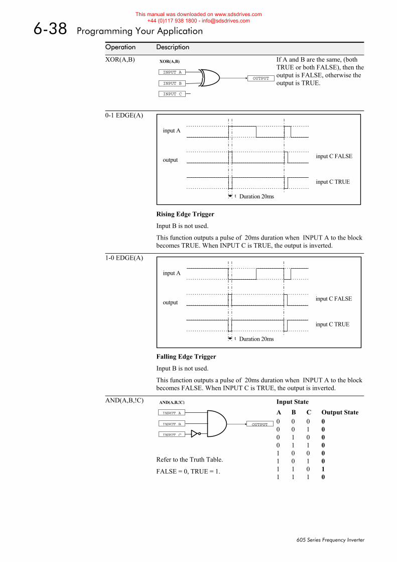
6-38 Programming Your Application
605 Series Frequency Inverter
Operation Description
XOR(A,B)
OUTPUT
INPUT A
INPUT B
INPUT C
XOR(A,B)
If A and B are the same, (both TRUE or both FALSE), then the output is FALSE, otherwise the output is TRUE.
0-1 EDGE(A)
input A
output input C FALSE
input C TRUE
Duration 20mst
Rising Edge Trigger
Input B is not used.
This function outputs a pulse of 20ms duration when INPUT A to the block becomes TRUE. When INPUT C is TRUE, the output is inverted.
1-0 EDGE(A)
input A
output input C FALSE
input C TRUE
Duration 20mst
Falling Edge Trigger
Input B is not used.
This function outputs a pulse of 20ms duration when INPUT A to the block becomes FALSE. When INPUT C is TRUE, the output is inverted.
AND(A,B,!C)
OUTPUT
INPUT A
INPUT B
INPUT C
AND(A,B,!C)
Refer to the Truth Table.
FALSE = 0, TRUE = 1.
Input State A B C Output State 0 0 0 0 0 0 1 0 0 1 0 0 0 1 1 0 1 0 0 0 1 0 1 0 1 1 0 1 1 1 1 0
This manual was downloaded on www.sdsdrives.com +44 (0)117 938 1800 - [email protected]
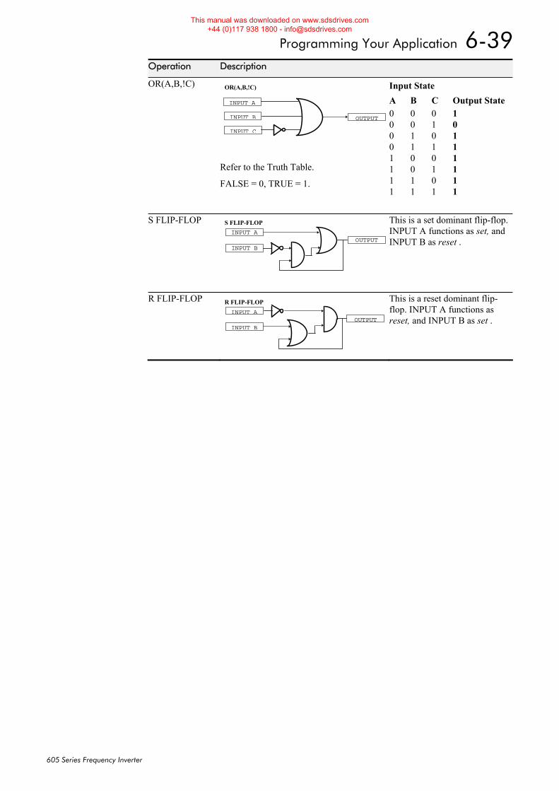
Programming Your Application 6-39
605 Series Frequency Inverter
Operation Description
OR(A,B,!C)
OUTPUT
INPUT A
INPUT B
INPUT C
OR(A,B,!C)
Refer to the Truth Table.
FALSE = 0, TRUE = 1.
Input State A B C Output State 0 0 0 1 0 0 1 0 0 1 0 1 0 1 1 1 1 0 0 1 1 0 1 1 1 1 0 1 1 1 1 1
S FLIP-FLOP
OUTPUTINPUT A
S FLIP-FLOP
INPUT B
This is a set dominant flip-flop. INPUT A functions as set, and INPUT B as reset .
R FLIP-FLOP
OUTPUTINPUT A
R FLIP-FLOP
INPUT B
This is a reset dominant flip-flop. INPUT A functions as reset, and INPUT B as set .
This manual was downloaded on www.sdsdrives.com +44 (0)117 938 1800 - [email protected]
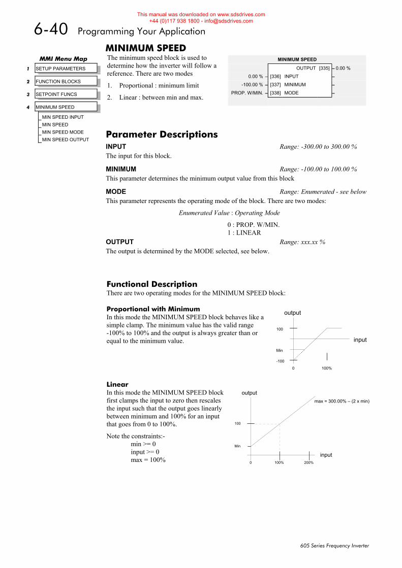
6-40 Programming Your Application
605 Series Frequency Inverter
MINIMUM SPEED The minimum speed block is used to determine how the inverter will follow a reference. There are two modes
1. Proportional : minimum limit
2. Linear : between min and max.
Functional Description There are two operating modes for the MINIMUM SPEED block:
Proportional with Minimum In this mode the MINIMUM SPEED block behaves like a simple clamp. The minimum value has the valid range -100% to 100% and the output is always greater than or equal to the minimum value.
Linear In this mode the MINIMUM SPEED block first clamps the input to zero then rescales the input such that the output goes linearly between minimum and 100% for an input that goes from 0 to 100%.
Note the constraints:- min >= 0 input >= 0 max = 100%
MMI Menu Map
1 SETUP PARAMETERS
2 FUNCTION BLOCKS
3 SETPOINT FUNCS
4 MINIMUM SPEED
MIN SPEED INPUT
MIN SPEED
MIN SPEED MODE
MIN SPEED OUTPUT
MINIMUM SPEED
OUTPUT [335] – 0.00 %
0.00 % – [336] INPUT –
-100.00 % – [337] MINIMUM –
PROP. W/MIN. – [338] MODE –
Parameter Descriptions INPUT Range: -300.00 to 300.00 % The input for this block.
MINIMUM Range: -100.00 to 100.00 % This parameter determines the minimum output value from this block
MODE Range: Enumerated - see belowThis parameter represents the operating mode of the block. There are two modes:
Enumerated Value : Operating Mode
0 : PROP. W/MIN. 1 : LINEAR
OUTPUT Range: xxx.xx % The output is determined by the MODE selected, see below.
Min
0 100%
100
-100
input
output
100
Min
0 100%
output
input200%
max = 300.00% – (2 x min)
This manual was downloaded on www.sdsdrives.com +44 (0)117 938 1800 - [email protected]
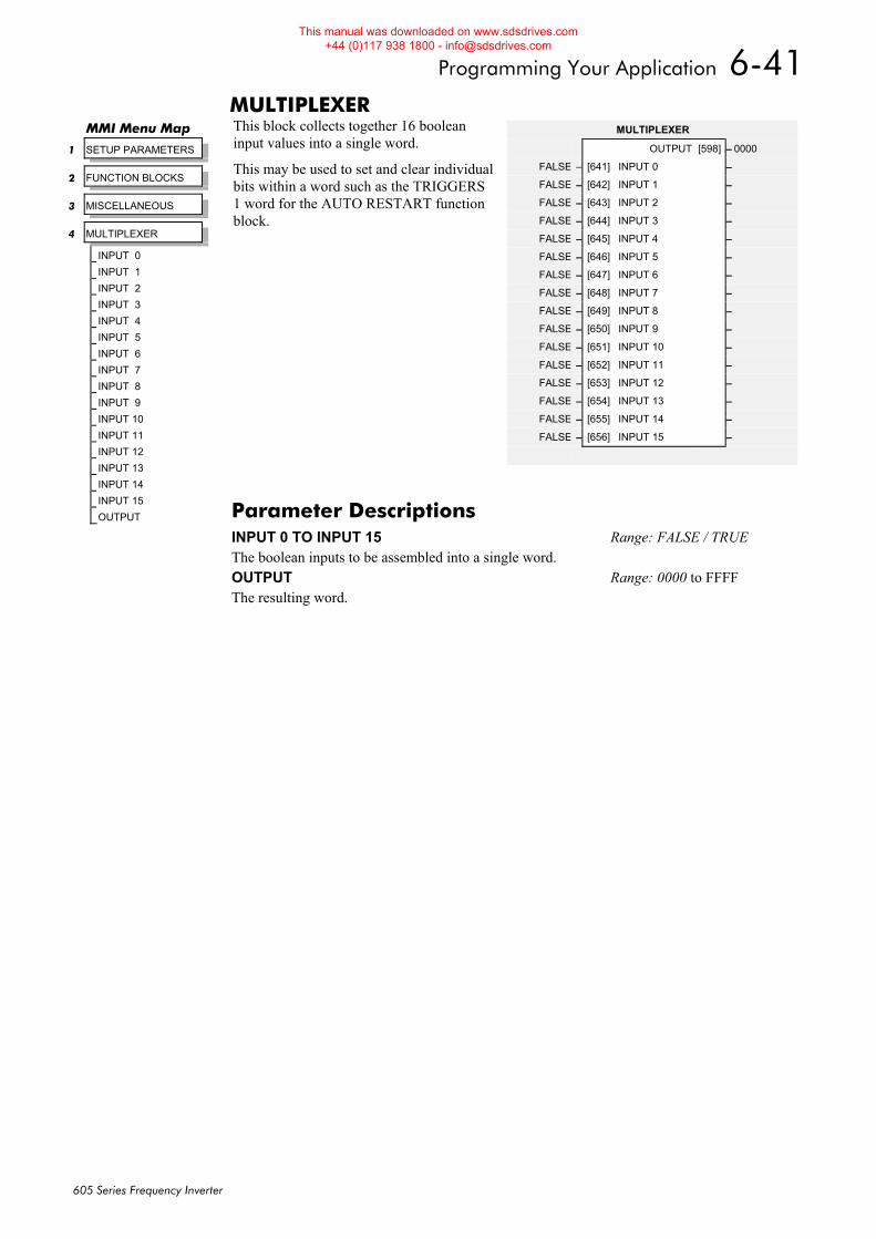
Programming Your Application 6-41
605 Series Frequency Inverter
MULTIPLEXER This block collects together 16 boolean input values into a single word.
This may be used to set and clear individual bits within a word such as the TRIGGERS 1 word for the AUTO RESTART function block.
MMI Menu Map
1 SETUP PARAMETERS
2 FUNCTION BLOCKS
3 MISCELLANEOUS
4 MULTIPLEXER
INPUT 0
INPUT 1
INPUT 2
INPUT 3
INPUT 4
INPUT 5
INPUT 6
INPUT 7
INPUT 8
INPUT 9
INPUT 10
INPUT 11
INPUT 12
INPUT 13
INPUT 14
INPUT 15
OUTPUT
MULTIPLEXER
OUTPUT [598] – 0000
FALSE – [641] INPUT 0 –
FALSE – [642] INPUT 1 –
FALSE – [643] INPUT 2 –
FALSE – [644] INPUT 3 –
FALSE – [645] INPUT 4 –
FALSE – [646] INPUT 5 –
FALSE – [647] INPUT 6 –
FALSE – [648] INPUT 7 –
FALSE – [649] INPUT 8 –
FALSE – [650] INPUT 9 –
FALSE – [651] INPUT 10 –
FALSE – [652] INPUT 11 –
FALSE – [653] INPUT 12 –
FALSE – [654] INPUT 13 –
FALSE – [655] INPUT 14 –
FALSE – [656] INPUT 15 –
Parameter Descriptions INPUT 0 TO INPUT 15 Range: FALSE / TRUE The boolean inputs to be assembled into a single word. OUTPUT Range: 0000 to FFFF The resulting word.
This manual was downloaded on www.sdsdrives.com +44 (0)117 938 1800 - [email protected]
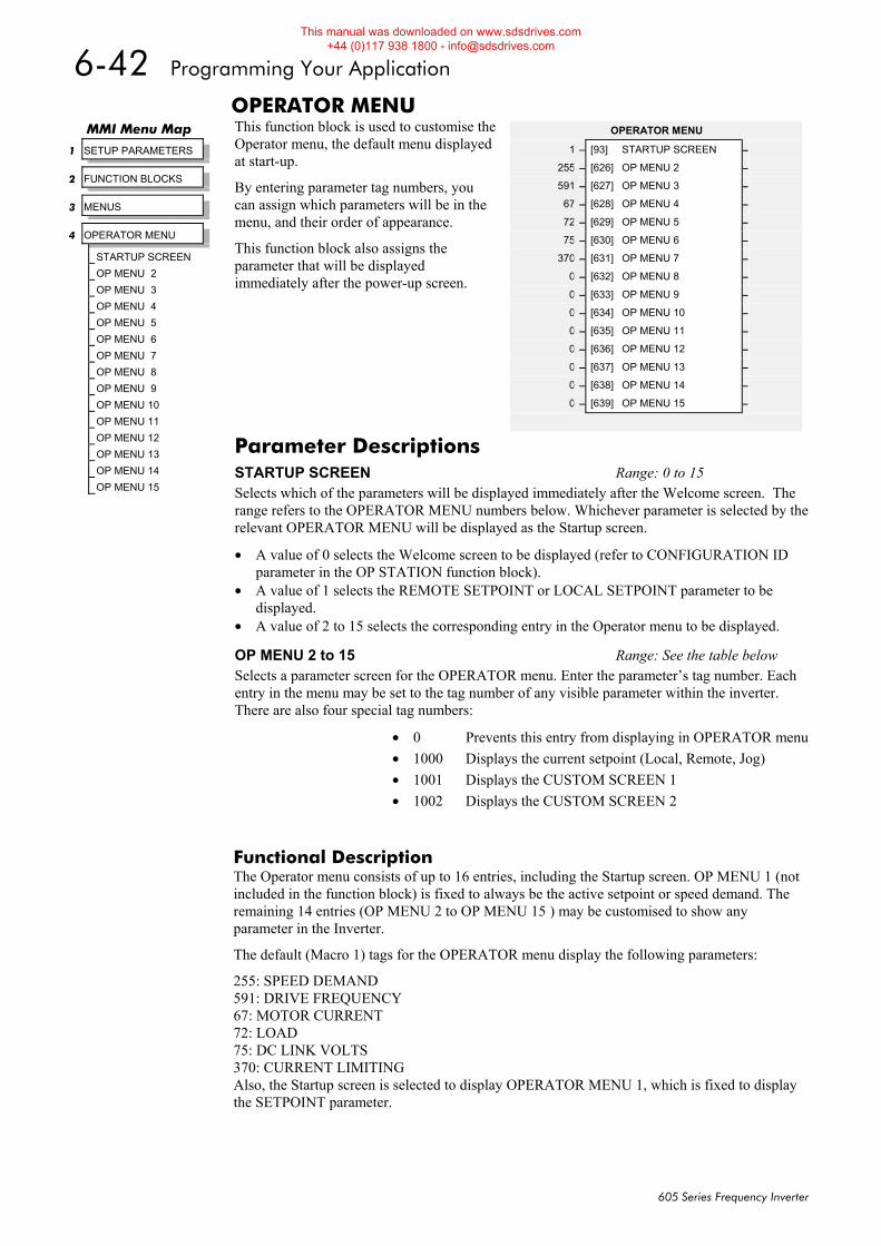
6-42 Programming Your Application
605 Series Frequency Inverter
OPERATOR MENU This function block is used to customise the Operator menu, the default menu displayed at start-up.
By entering parameter tag numbers, you can assign which parameters will be in the menu, and their order of appearance.
This function block also assigns the parameter that will be displayed immediately after the power-up screen.
Functional Description The Operator menu consists of up to 16 entries, including the Startup screen. OP MENU 1 (not included in the function block) is fixed to always be the active setpoint or speed demand. The remaining 14 entries (OP MENU 2 to OP MENU 15 ) may be customised to show any parameter in the Inverter.
The default (Macro 1) tags for the OPERATOR menu display the following parameters:
255: SPEED DEMAND 591: DRIVE FREQUENCY 67: MOTOR CURRENT 72: LOAD 75: DC LINK VOLTS 370: CURRENT LIMITING Also, the Startup screen is selected to display OPERATOR MENU 1, which is fixed to display the SETPOINT parameter.
MMI Menu Map
1 SETUP PARAMETERS
2 FUNCTION BLOCKS
3 MENUS
4 OPERATOR MENU
STARTUP SCREEN
OP MENU 2
OP MENU 3
OP MENU 4
OP MENU 5
OP MENU 6
OP MENU 7
OP MENU 8
OP MENU 9
OP MENU 10
OP MENU 11
OP MENU 12
OP MENU 13
OP MENU 14
OP MENU 15
OPERATOR MENU
1 – [93] STARTUP SCREEN –
255 – [626] OP MENU 2 –
591 – [627] OP MENU 3 –
67 – [628] OP MENU 4 –
72 – [629] OP MENU 5 –
75 – [630] OP MENU 6 –
370 – [631] OP MENU 7 –
0 – [632] OP MENU 8 –
0 – [633] OP MENU 9 –
0 – [634] OP MENU 10 –
0 – [635] OP MENU 11 –
0 – [636] OP MENU 12 –
0 – [637] OP MENU 13 –
0 – [638] OP MENU 14 –
0 – [639] OP MENU 15 –
Parameter Descriptions STARTUP SCREEN Range: 0 to 15 Selects which of the parameters will be displayed immediately after the Welcome screen. The range refers to the OPERATOR MENU numbers below. Whichever parameter is selected by the relevant OPERATOR MENU will be displayed as the Startup screen.
• A value of 0 selects the Welcome screen to be displayed (refer to CONFIGURATION ID parameter in the OP STATION function block).
• A value of 1 selects the REMOTE SETPOINT or LOCAL SETPOINT parameter to be displayed.
• A value of 2 to 15 selects the corresponding entry in the Operator menu to be displayed.
OP MENU 2 to 15 Range: See the table below Selects a parameter screen for the OPERATOR menu. Enter the parameter’s tag number. Each entry in the menu may be set to the tag number of any visible parameter within the inverter. There are also four special tag numbers:
• 0 Prevents this entry from displaying in OPERATOR menu• 1000 Displays the current setpoint (Local, Remote, Jog) • 1001 Displays the CUSTOM SCREEN 1 • 1002 Displays the CUSTOM SCREEN 2
This manual was downloaded on www.sdsdrives.com +44 (0)117 938 1800 - [email protected]
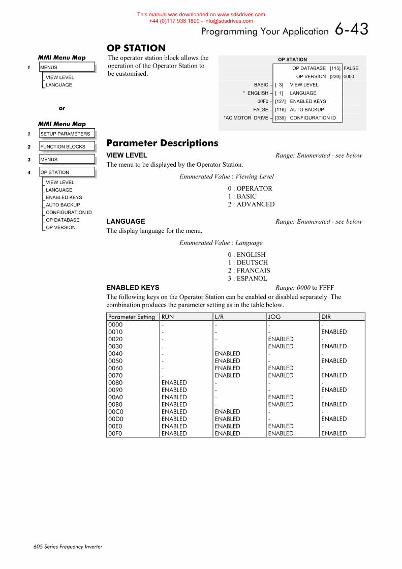
Programming Your Application 6-43
605 Series Frequency Inverter
OP STATION The operator station block allows the operation of the Operator Station to be customised.
OP STATION
OP DATABASE [115] –FALSE
OP VERSION [230] –0000
BASIC – [ 3] VIEW LEVEL –
* ENGLISH – [ 1] LANGUAGE –
00F0 – [127] ENABLED KEYS –
FALSE – [116] AUTO BACKUP –
*AC MOTOR DRIVE – [339] CONFIGURATION ID –
MMI Menu Map
1 MENUS
VIEW LEVEL
LANGUAGE
or
MMI Menu Map
1 SETUP PARAMETERS
2 FUNCTION BLOCKS
3 MENUS
4 OP STATION
VIEW LEVEL
LANGUAGE
ENABLED KEYS
AUTO BACKUP
CONFIGURATION ID
OP DATABASE
OP VERSION
Parameter Descriptions VIEW LEVEL Range: Enumerated - see belowThe menu to be displayed by the Operator Station.
Enumerated Value : Viewing Level
0 : OPERATOR 1 : BASIC 2 : ADVANCED
LANGUAGE Range: Enumerated - see belowThe display language for the menu.
Enumerated Value : Language
0 : ENGLISH 1 : DEUTSCH 2 : FRANCAIS 3 : ESPANOL
ENABLED KEYS Range: 0000 to FFFF The following keys on the Operator Station can be enabled or disabled separately. The combination produces the parameter setting as in the table below.
Parameter Setting RUN L/R JOG DIR 0000 0010 0020 0030 0040 0050 0060 0070 0080 0090 00A0 00B0 00C0 00D0 00E0 00F0
- - - - - - - - ENABLED ENABLED ENABLED ENABLED ENABLED ENABLED ENABLED ENABLED
- - - - ENABLED ENABLED ENABLED ENABLED - - - - ENABLED ENABLED ENABLED ENABLED
- - ENABLED ENABLED - - ENABLED ENABLED - - ENABLED ENABLED - - ENABLED ENABLED
- ENABLED - ENABLED - ENABLED - ENABLED - ENABLED - ENABLED - ENABLED - ENABLED
This manual was downloaded on www.sdsdrives.com +44 (0)117 938 1800 - [email protected]

6-44 Programming Your Application
605 Series Frequency Inverter
AUTO BACKUP Range: FALSE / TRUE When this input is set to TRUE, performing a SAVE TO MEMORY function block operation also saves the configuration of the inverter to the connected Operator Station. CONFIGURATION ID Range: 16 characters This 16 character string is displayed as the top line of the Welcome screen. OP DATABASE Range: FALSE / TRUE When TRUE, this diagnostic output indicates that the connected Operator Station contains a configuration that may be loaded into the inverter. OP VERSION Range: 0000 to FFFF Displays the software version of the Operator Station. It is cleared to 0000 if no Operator Station is connected.
This manual was downloaded on www.sdsdrives.com +44 (0)117 938 1800 - [email protected]
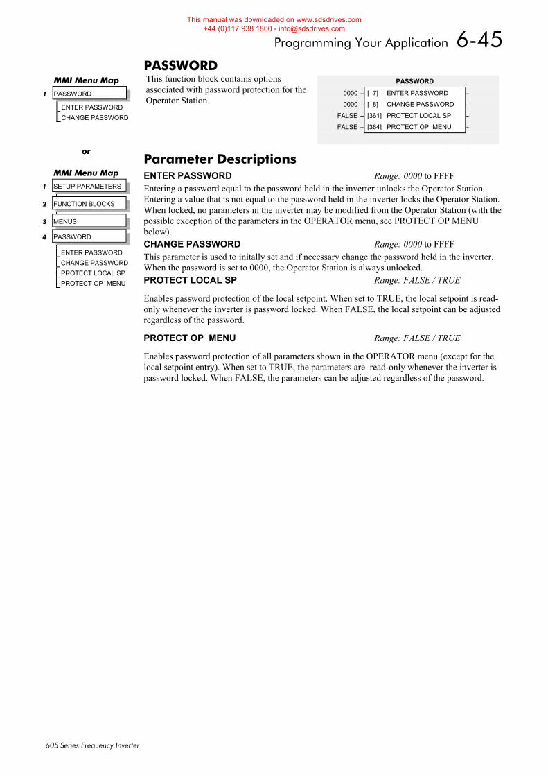
Programming Your Application 6-45
605 Series Frequency Inverter
PASSWORD This function block contains options associated with password protection for the Operator Station.
MMI Menu Map
1 PASSWORD
ENTER PASSWORD
CHANGE PASSWORD
PASSWORD
0000 – [ 7] ENTER PASSWORD –
0000 – [ 8] CHANGE PASSWORD –
FALSE – [361] PROTECT LOCAL SP –
FALSE – [364] PROTECT OP MENU –
or
MMI Menu Map
1 SETUP PARAMETERS
2 FUNCTION BLOCKS
3 MENUS
4 PASSWORD
ENTER PASSWORD
CHANGE PASSWORD
PROTECT LOCAL SP
PROTECT OP MENU
Parameter Descriptions ENTER PASSWORD Range: 0000 to FFFF Entering a password equal to the password held in the inverter unlocks the Operator Station. Entering a value that is not equal to the password held in the inverter locks the Operator Station.When locked, no parameters in the inverter may be modified from the Operator Station (with the possible exception of the parameters in the OPERATOR menu, see PROTECT OP MENU below). CHANGE PASSWORD Range: 0000 to FFFF This parameter is used to initally set and if necessary change the password held in the inverter. When the password is set to 0000, the Operator Station is always unlocked. PROTECT LOCAL SP Range: FALSE / TRUE
Enables password protection of the local setpoint. When set to TRUE, the local setpoint is read-only whenever the inverter is password locked. When FALSE, the local setpoint can be adjusted regardless of the password.
PROTECT OP MENU Range: FALSE / TRUE
Enables password protection of all parameters shown in the OPERATOR menu (except for the local setpoint entry). When set to TRUE, the parameters are read-only whenever the inverter is password locked. When FALSE, the parameters can be adjusted regardless of the password.
This manual was downloaded on www.sdsdrives.com +44 (0)117 938 1800 - [email protected]
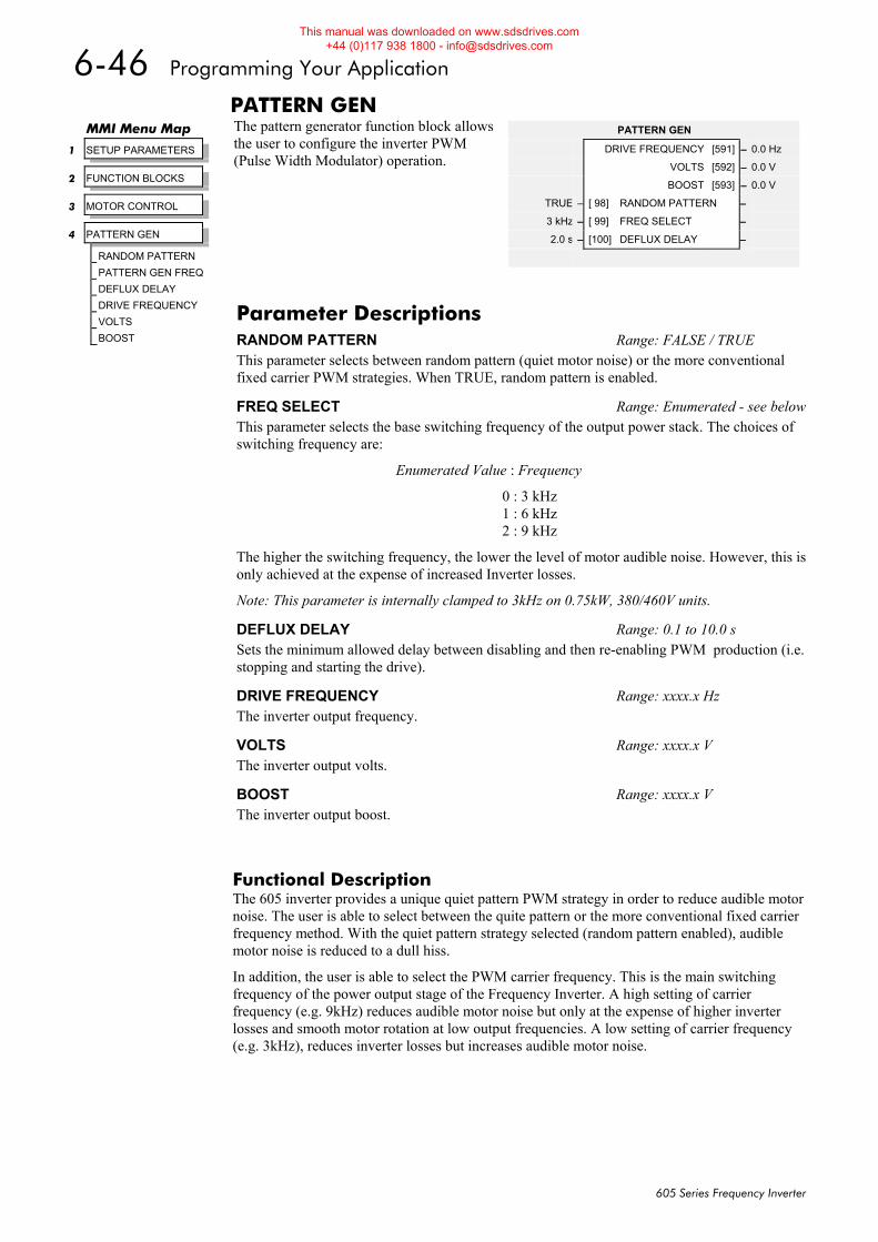
6-46 Programming Your Application
605 Series Frequency Inverter
PATTERN GEN The pattern generator function block allows the user to configure the inverter PWM (Pulse Width Modulator) operation.
Functional Description The 605 inverter provides a unique quiet pattern PWM strategy in order to reduce audible motor noise. The user is able to select between the quite pattern or the more conventional fixed carrier frequency method. With the quiet pattern strategy selected (random pattern enabled), audible motor noise is reduced to a dull hiss.
In addition, the user is able to select the PWM carrier frequency. This is the main switching frequency of the power output stage of the Frequency Inverter. A high setting of carrier frequency (e.g. 9kHz) reduces audible motor noise but only at the expense of higher inverter losses and smooth motor rotation at low output frequencies. A low setting of carrier frequency (e.g. 3kHz), reduces inverter losses but increases audible motor noise.
MMI Menu Map
1 SETUP PARAMETERS
2 FUNCTION BLOCKS
3 MOTOR CONTROL
4 PATTERN GEN
RANDOM PATTERN
PATTERN GEN FREQ
DEFLUX DELAY
DRIVE FREQUENCY
VOLTS
BOOST
PATTERN GEN
DRIVE FREQUENCY [591] – 0.0 Hz
VOLTS [592] – 0.0 V
BOOST [593] – 0.0 V
TRUE – [ 98] RANDOM PATTERN –
3 kHz – [ 99] FREQ SELECT –
2.0 s – [100] DEFLUX DELAY –
Parameter Descriptions RANDOM PATTERN Range: FALSE / TRUE This parameter selects between random pattern (quiet motor noise) or the more conventional fixed carrier PWM strategies. When TRUE, random pattern is enabled.
FREQ SELECT Range: Enumerated - see belowThis parameter selects the base switching frequency of the output power stack. The choices of switching frequency are:
Enumerated Value : Frequency
0 : 3 kHz 1 : 6 kHz 2 : 9 kHz
The higher the switching frequency, the lower the level of motor audible noise. However, this is only achieved at the expense of increased Inverter losses.
Note: This parameter is internally clamped to 3kHz on 0.75kW, 380/460V units.
DEFLUX DELAY Range: 0.1 to 10.0 s Sets the minimum allowed delay between disabling and then re-enabling PWM production (i.e. stopping and starting the drive).
DRIVE FREQUENCY Range: xxxx.x Hz The inverter output frequency.
VOLTS Range: xxxx.x V The inverter output volts.
BOOST Range: xxxx.x V The inverter output boost.
This manual was downloaded on www.sdsdrives.com +44 (0)117 938 1800 - [email protected]
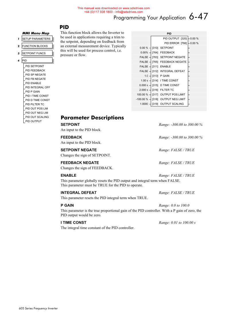
Programming Your Application 6-47
605 Series Frequency Inverter
PID This function block allows the Inverter to be used in applications requiring a trim to the setpoint, depending on feedback from an external measurement device. Typically this will be used for process control, i.e. pressure or flow.
MMI Menu Map
1 SETUP PARAMETERS
2 FUNCTION BLOCKS
3 SETPOINT FUNCS
4 PID
PID SETPOINT
PID FEEDBACK
PID SP NEGATE
PID FB NEGATE
PID ENABLE
PID INTEGRAL OFF
PID P GAIN
PID I TIME CONST
PID D TIME CONST
PID FILTER TC
PID OUT POS LIM
PID OUT NEG LIM
PID OUT SCALING
PID OUTPUT
PID
PID OUTPUT [320] – 0.00 %
PID ERROR [766] – 0.00 %
0.00 % – [310] SETPOINT –
0.00% – [764] FEEDBACK –
FALSE – [763] SETPOINT NEGATE –
FALSE – [765] FEEDBACK NEGATE –
FALSE – [311] ENABLE –
FALSE – [312] INTEGRAL DEFEAT –
1.0 – [313] P GAIN –
1.00 s – [314] I TIME CONST –
0.000 s – [315] D TIME CONST –
2.000 s – [316] FILTER TC –
100.00 % – [317] OUTPUT POS LIMIT –
-100.00 % – [318] OUTPUT NEG LIMIT –
1.0000 – [319] OUTPUT SCALING –
Parameter Descriptions SETPOINT Range: -300.00 to 300.00 % An input to the PID block.
FEEDBACK Range: -300.00 to 300.00 % An input to the PID block.
SETPOINT NEGATE Range: FALSE / TRUE Changes the sign of SETPOINT.
FEEDBACK NEGATE Range: FALSE / TRUE Changes the sign of FEEDBACK.
ENABLE Range: FALSE / TRUE This parameter globally resets the PID output and integral term when FALSE. This parameter must be TRUE for the PID to operate.
INTEGRAL DEFEAT Range: FALSE / TRUE This parameter resets the PID integral term when TRUE.
P GAIN Range: 0.0 to 100.0 This parameter is the true proportional gain of the PID controller. With a P gain of zero, the PID output would be zero.
I TIME CONST Range: 0.01 to 100.00 s The integral time constant of the PID controller.
This manual was downloaded on www.sdsdrives.com +44 (0)117 938 1800 - [email protected]
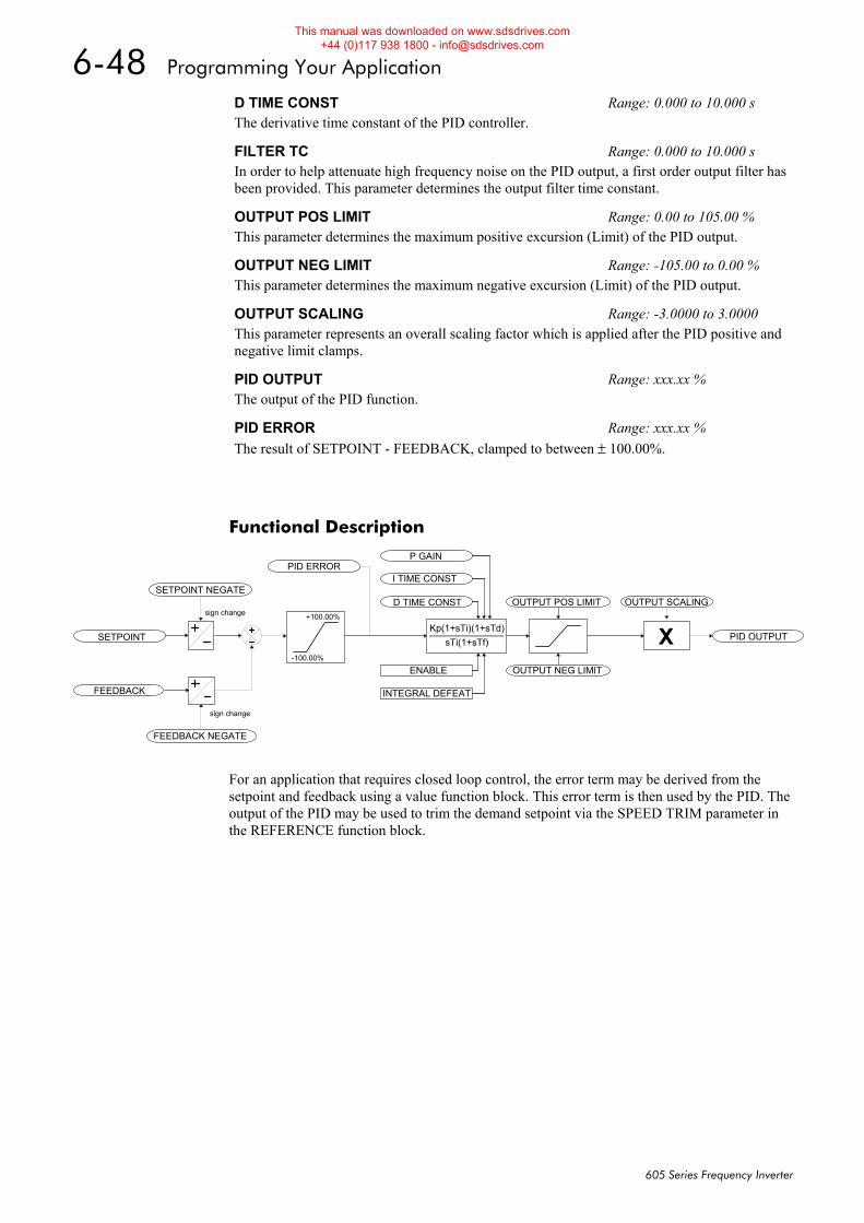
6-48 Programming Your Application
605 Series Frequency Inverter
Functional Description
Kp(1+sTi)(1+sTd)sTi(1+sTf)
D TIME CONST
I TIME CONST
P GAIN
ENABLE
INTEGRAL DEFEAT
X PID OUTPUT
OUTPUT NEG LIMIT
OUTPUT POS LIMIT OUTPUT SCALING
SETPOINT
FEEDBACK
SETPOINT NEGATE
FEEDBACK NEGATE
+100.00%
-100.00%
PID ERROR
sign change
sign change
For an application that requires closed loop control, the error term may be derived from the setpoint and feedback using a value function block. This error term is then used by the PID. The output of the PID may be used to trim the demand setpoint via the SPEED TRIM parameter in the REFERENCE function block.
D TIME CONST Range: 0.000 to 10.000 s The derivative time constant of the PID controller.
FILTER TC Range: 0.000 to 10.000 s In order to help attenuate high frequency noise on the PID output, a first order output filter has been provided. This parameter determines the output filter time constant.
OUTPUT POS LIMIT Range: 0.00 to 105.00 % This parameter determines the maximum positive excursion (Limit) of the PID output.
OUTPUT NEG LIMIT Range: -105.00 to 0.00 % This parameter determines the maximum negative excursion (Limit) of the PID output.
OUTPUT SCALING Range: -3.0000 to 3.0000 This parameter represents an overall scaling factor which is applied after the PID positive and negative limit clamps.
PID OUTPUT Range: xxx.xx % The output of the PID function.
PID ERROR Range: xxx.xx % The result of SETPOINT - FEEDBACK, clamped to between ± 100.00%.
This manual was downloaded on www.sdsdrives.com +44 (0)117 938 1800 - [email protected]
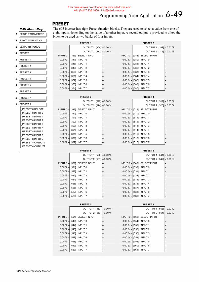
Programming Your Application 6-49
605 Series Frequency Inverter
PRESET The 605 inverter has eight Preset function blocks. They are used to select a value from one of eight inputs, depending on the value of another input. A second output is provided to allow the block to be used as two banks of four inputs.
.
MMI Menu Map
1 SETUP PARAMETERS
2 FUNCTION BLOCKS
3 SETPOINT FUNCS
4 PRESET
5 PRESET 1
5 PRESET 2
5 PRESET 3
5 PRESET 4
5 PRESET 5
5 PRESET 6
5 PRESET 7
5 PRESET 8
PRESET 8 SELECT
PRESET 8 INPUT 0
PRESET 8 INPUT 1
PRESET 8 INPUT 2
PRESET 8 INPUT 3
PRESET 8 INPUT 4
PRESET 8 INPUT 5
PRESET 8 INPUT 6
PRESET 8 INPUT 7
PRESET 8 OUTPUT1
PRESET 8 OUTPUT2
PRESET 2
OUTPUT 1 [389] – 0.00 %
OUTPUT 2 [373] – 0.00 %
INPUT 0 – [388] SELECT INPUT –
0.00 % – [380] INPUT 0 –
0.00 % – [381] INPUT 1 –
0.00 % – [382] INPUT 2 –
0.00 % – [383] INPUT 3 –
0.00 % – [384] INPUT 4 –
0.00 % – [385] INPUT 5 –
0.00 % – [386] INPUT 6 –
0.00 % – [387] INPUT 7 –
PRESET 4
OUTPUT 1 [519] – 0.00 %
OUTPUT 2 [520] – 0.00 %
INPUT 0 – [518] SELECT INPUT –
0.00 % – [510] INPUT 0 –
0.00 % – [511] INPUT 1 –
0.00 % – [512] INPUT 2 –
0.00 % – [513] INPUT 3 –
0.00 % – [514] INPUT 4 –
0.00 % – [515] INPUT 5 –
0.00 % – [516] INPUT 6 –
0.00 % – [517] INPUT 7 –
PRESET 6
OUTPUT 1 [541] – 0.00 %
OUTPUT 2 [542] – 0.00 %
INPUT 0 – [540] SELECT INPUT –
0.00 % – [532] INPUT 0 –
0.00 % – [533] INPUT 1 –
0.00 % – [534] INPUT 2 –
0.00 % – [535] INPUT 3 –
0.00 % – [536] INPUT 4 –
0.00 % – [537] INPUT 5 –
0.00 % – [538] INPUT 6 –
0.00 % – [539] INPUT 7 –
PRESET 8
OUTPUT 1 [563] – 0.00 %
OUTPUT 2 [564] – 0.00 %
INPUT 0 – [562] SELECT INPUT –
0.00 % – [554] INPUT 0 –
0.00 % – [555] INPUT 1 –
0.00 % – [556] INPUT 2 –
0.00 % – [557] INPUT 3 –
0.00 % – [558] INPUT 4 –
0.00 % – [559] INPUT 5 –
0.00 % – [560] INPUT 6 –
0.00 % – [561] INPUT 7 –
PRESET 1
OUTPUT 1 [356] – 0.00 %
OUTPUT 2 [372] – 0.00 %
INPUT 0 – [355] SELECT INPUT –
0.00 % – [347] INPUT 0 –
0.00 % – [348] INPUT 1 –
0.00 % – [349] INPUT 2 –
0.00 % – [350] INPUT 3 –
0.00 % – [351] INPUT 4 –
0.00 % – [352] INPUT 5 –
0.00 % – [353] INPUT 6 –
0.00 % – [354] INPUT 7 –
PRESET 3
OUTPUT 1 [399] – 0.00 %
OUTPUT 2 [374] – 0.00 %
INPUT 0 – [398] SELECT INPUT –
0.00 % – [390] INPUT 0 –
0.00 % – [391] INPUT 1 –
0.00 % – [392] INPUT 2 –
0.00 % – [393] INPUT 3 –
0.00 % – [394] INPUT 4 –
0.00 % – [395] INPUT 5 –
0.00 % – [396] INPUT 6 –
0.00 % – [397] INPUT 7 –
PRESET 5
OUTPUT 1 [530] – 0.00 %
OUTPUT 2 [531] – 0.00 %
INPUT 0 – [529] SELECT INPUT –
0.00 % – [521] INPUT 0 –
0.00 % – [522] INPUT 1 –
0.00 % – [523] INPUT 2 –
0.00 % – [524] INPUT 3 –
0.00 % – [525] INPUT 4 –
0.00 % – [526] INPUT 5 –
0.00 % – [527] INPUT 6 –
0.00 % – [528] INPUT 7 –
PRESET 7
OUTPUT 1 [552] – 0.00 %
OUTPUT 2 [553] – 0.00 %
INPUT 0 – [551] SELECT INPUT –
0.00 % – [543] INPUT 0 –
0.00 % – [544] INPUT 1 –
0.00 % – [545] INPUT 2 –
0.00 % – [546] INPUT 3 –
0.00 % – [547] INPUT 4 –
0.00 % – [548] INPUT 5 –
0.00 % – [549] INPUT 6 –
0.00 % – [550] INPUT 7 –
This manual was downloaded on www.sdsdrives.com +44 (0)117 938 1800 - [email protected]
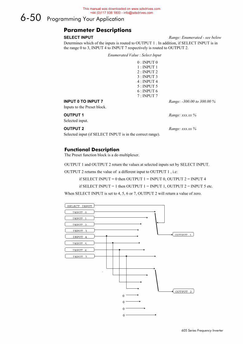
6-50 Programming Your Application
605 Series Frequency Inverter
Functional Description The Preset function block is a de-multiplexer. OUTPUT 1 and OUTPUT 2 return the values at selected inputs set by SELECT INPUT.
OUTPUT 2 returns the value of a different input to OUTPUT 1 , i.e:
if SELECT INPUT = 0 then OUTPUT 1 = INPUT 0, OUTPUT 2 = INPUT 4
if SELECT INPUT = 1 then OUTPUT 1 = INPUT 1, OUTPUT 2 = INPUT 5 etc.
When SELECT INPUT is set to 4, 5, 6 or 7, OUTPUT 2 will return a value of zero.
Parameter Descriptions SELECT INPUT Range: Enumerated - see belowDetermines which of the inputs is routed to OUTPUT 1 . In addition, if SELECT INPUT is in the range 0 to 3, INPUT 4 to INPUT 7 respectively is routed to OUTPUT 2.
Enumerated Value : Select Input
0 : INPUT 0 1 : INPUT 1 2 : INPUT 2 3 : INPUT 3 4 : INPUT 4 5 : INPUT 5 6 : INPUT 6 7 : INPUT 7
INPUT 0 TO INPUT 7 Range: -300.00 to 300.00 % Inputs to the Preset block.
OUTPUT 1 Range: xxx.xx % Selected input.
OUTPUT 2 Range: xxx.xx % Selected input (if SELECT INPUT is in the correct range).
OUTPUT 1
SELECT INPUT
INPUT 0
INPUT 1
INPUT 2
INPUT 3
INPUT 4
INPUT 5
INPUT 6
INPUT 7
OUTPUT 20
0
0
0
This manual was downloaded on www.sdsdrives.com +44 (0)117 938 1800 - [email protected]
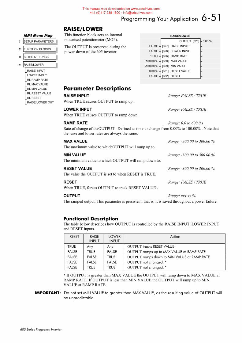
Programming Your Application 6-51
605 Series Frequency Inverter
RAISE/LOWER This function block acts an internal motorised potentiometer (MOP).
The OUTPUT is preserved during the power-down of the 605 inverter.
Functional Description The table below describes how OUTPUT is controlled by the RAISE INPUT, LOWER INPUT and RESET inputs.
RESET RAISE INPUT
LOWER INPUT
Action
TRUE Any Any OUTPUT tracks RESET VALUE FALSE TRUE FALSE OUTPUT ramps up to MAX VALUE at RAMP RATE FALSE FALSE TRUE OUTPUT ramps down to MIN VALUE at RAMP RATE FALSE FALSE FALSE OUTPUT not changed. * FALSE TRUE TRUE OUTPUT not changed. *
* If OUTPUT is greater than MAX VALUE the OUTPUT will ramp down to MAX VALUE at RAMP RATE. If OUTPUT is less than MIN VALUE the OUTPUT will ramp up to MIN VALUE at RAMP RATE.
IMPORTANT: Do not set MIN VALUE to greater than MAX VALUE, as the resulting value of OUTPUT will be unpredictable.
MMI Menu Map
1 SETUP PARAMETERS
2 FUNCTION BLOCKS
3 SETPOINT FUNCS
4 RAISE/LOWER
RAISE INPUT
LOWER INPUT
RL RAMP RATE
RL MAX VALUE
RL MIN VALUE
RL RESET VALUE
RL RESET
RAISE/LOWER OUT
RAISE/LOWER
OUTPUT [325] – 0.00 %
FALSE – [327] RAISE INPUT –
FALSE – [328] LOWER INPUT –
10.0 s – [326] RAMP RATE –
100.00 % – [330] MAX VALUE –
-100.00 % – [329] MIN VALUE –
0.00 % – [331] RESET VALUE –
FALSE – [332] RESET –
Parameter Descriptions RAISE INPUT Range: FALSE / TRUE When TRUE causes OUTPUT to ramp up.
LOWER INPUT Range: FALSE / TRUE When TRUE causes OUTPUT to ramp down.
RAMP RATE Range: 0.0 to 600.0 s Rate of change of theOUTPUT . Defined as time to change from 0.00% to 100.00% . Note that the raise and lower rates are always the same.
MAX VALUE Range: -300.00 to 300.00 % The maximum value to whichOUTPUT will ramp up to.
MIN VALUE Range: -300.00 to 300.00 % The minimum value to which OUTPUT will ramp down to.
RESET VALUE Range: -300.00 to 300.00 % The value the OUTPUT is set to when RESET is TRUE.
RESET Range: FALSE / TRUE When TRUE, forces OUTPUT to track RESET VALUE .
OUTPUT Range: xxx.xx % The ramped output. This parameter is persistent, that is, it is saved throughout a power failure.
This manual was downloaded on www.sdsdrives.com +44 (0)117 938 1800 - [email protected]
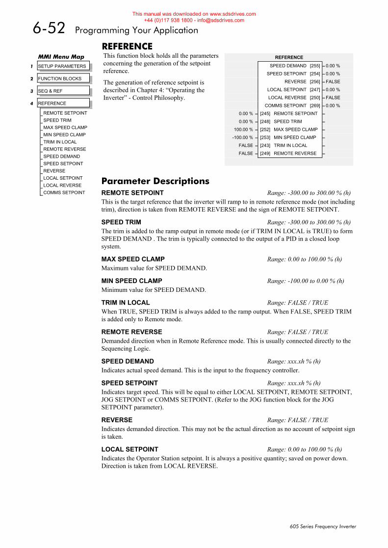
6-52 Programming Your Application
605 Series Frequency Inverter
REFERENCE This function block holds all the parameters concerning the generation of the setpoint reference.
The generation of reference setpoint is described in Chapter 4: “Operating the Inverter” - Control Philosophy.
MMI Menu Map
1 SETUP PARAMETERS
2 FUNCTION BLOCKS
3 SEQ & REF
4 REFERENCE
REMOTE SETPOINT
SPEED TRIM
MAX SPEED CLAMP
MIN SPEED CLAMP
TRIM IN LOCAL
REMOTE REVERSE
SPEED DEMAND
SPEED SETPOINT
REVERSE
LOCAL SETPOINT
LOCAL REVERSE
COMMS SETPOINT
REFERENCE
SPEED DEMAND [255] – 0.00 %
SPEED SETPOINT [254] – 0.00 %
REVERSE [256] – FALSE
LOCAL SETPOINT [247] – 0.00 %
LOCAL REVERSE [250] – FALSE
COMMS SETPOINT [269] – 0.00 %
0.00 % – [245] REMOTE SETPOINT –
0.00 % – [248] SPEED TRIM –
100.00 % – [252] MAX SPEED CLAMP –
-100.00 % – [253] MIN SPEED CLAMP –
FALSE – [243] TRIM IN LOCAL –
FALSE – [249] REMOTE REVERSE –
Parameter Descriptions REMOTE SETPOINT Range: -300.00 to 300.00 % (h) This is the target reference that the inverter will ramp to in remote reference mode (not including trim), direction is taken from REMOTE REVERSE and the sign of REMOTE SETPOINT.
SPEED TRIM Range: -300.00 to 300.00 % (h) The trim is added to the ramp output in remote mode (or if TRIM IN LOCAL is TRUE) to form SPEED DEMAND . The trim is typically connected to the output of a PID in a closed loop system.
MAX SPEED CLAMP Range: 0.00 to 100.00 % (h) Maximum value for SPEED DEMAND.
MIN SPEED CLAMP Range: -100.00 to 0.00 % (h) Minimum value for SPEED DEMAND.
TRIM IN LOCAL Range: FALSE / TRUE When TRUE, SPEED TRIM is always added to the ramp output. When FALSE, SPEED TRIM is added only to Remote mode.
REMOTE REVERSE Range: FALSE / TRUE Demanded direction when in Remote Reference mode. This is usually connected directly to the Sequencing Logic.
SPEED DEMAND Range: xxx.xh % (h) Indicates actual speed demand. This is the input to the frequency controller.
SPEED SETPOINT Range: xxx.xh % (h) Indicates target speed. This will be equal to either LOCAL SETPOINT, REMOTE SETPOINT, JOG SETPOINT or COMMS SETPOINT. (Refer to the JOG function block for the JOG SETPOINT parameter).
REVERSE Range: FALSE / TRUE Indicates demanded direction. This may not be the actual direction as no account of setpoint sign is taken.
LOCAL SETPOINT Range: 0.00 to 100.00 % (h) Indicates the Operator Station setpoint. It is always a positive quantity; saved on power down. Direction is taken from LOCAL REVERSE.
This manual was downloaded on www.sdsdrives.com +44 (0)117 938 1800 - [email protected]
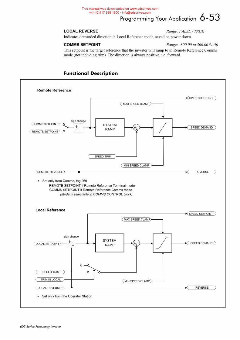
Programming Your Application 6-53
605 Series Frequency Inverter
Functional Description
LOCAL REVERSE Range: FALSE / TRUE Indicates demanded direction in Local Reference mode, saved on power down.
COMMS SETPOINT Range: -300.00 to 300.00 % (h) This setpoint is the target reference that the inverter will ramp to in Remote Reference Comms mode (not including trim). The direction is always positive, i.e. forward.
MAX SPEED CLAMP
MIN SPEED CLAMP
SPEED SETPOINT
SPEED DEMAND
REVERSE
SPEED TRIM
REMOTE SETPOINT *
REMOTE REVERSE *
SYSTEMRAMP
MAX SPEED CLAMP
MIN SPEED CLAMP
SPEED SETPOINT
SPEED DEMAND
REVERSE
SPEED TRIM
TRIM IN LOCAL
LOCAL SETPOINT *
LOCAL REVERSE *
SYSTEMRAMP
0
COMMS SETPOINT *
* Set only from Comms, tag 269REMOTE SETPOINT if Remote Reference Terminal modeCOMMS SETPOINT if Remote Reference Comms mode
* Set only from the Operator Station
(Mode is selectable in COMMS CONTROL block)
Remote Reference
Local Reference
sign change
sign change
++
++
This manual was downloaded on www.sdsdrives.com +44 (0)117 938 1800 - [email protected]
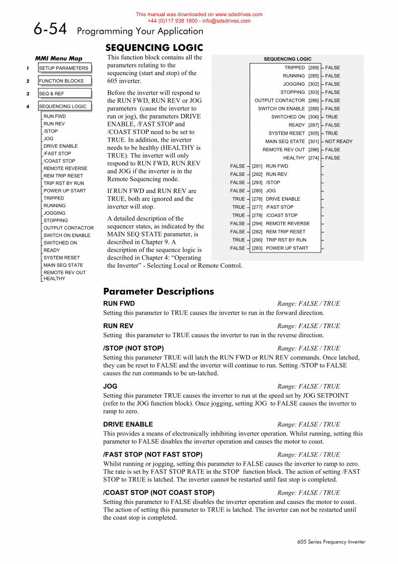
6-54 Programming Your Application
605 Series Frequency Inverter
SEQUENCING LOGIC This function block contains all the parameters relating to the sequencing (start and stop) of the 605 inverter.
Before the inverter will respond to the RUN FWD, RUN REV or JOG parameters (cause the inverter to run or jog), the parameters DRIVE ENABLE, /FAST STOP and /COAST STOP need to be set to TRUE. In addition, the inverter needs to be healthy (HEALTHY is TRUE). The inverter will only respond to RUN FWD, RUN REV and JOG if the inverter is in the Remote Sequencing mode.
If RUN FWD and RUN REV are TRUE, both are ignored and the inverter will stop.
A detailed description of the sequencer states, as indicated by the MAIN SEQ STATE parameter, is described in Chapter 9. A description of the sequence logic is described in Chapter 4: “Operating the Inverter” - Selecting Local or Remote Control.
MMI Menu Map
1 SETUP PARAMETERS
2 FUNCTION BLOCKS
3 SEQ & REF
4 SEQUENCING LOGIC
RUN FWD
RUN REV
/STOP
JOG
DRIVE ENABLE
/FAST STOP
/COAST STOP
REMOTE REVERSE
REM TRIP RESET
TRIP RST BY RUN
POWER UP START
TRIPPED
RUNNING
JOGGING
STOPPING
OUTPUT CONTACTOR
SWITCH ON ENABLE
SWITCHED ON
READY
SYSTEM RESET
MAIN SEQ STATE
REMOTE REV OUT HEALTHY
SEQUENCING LOGIC
TRIPPED [289] – FALSE
RUNNING [285] – FALSE
JOGGING [302] – FALSE
STOPPING [303] – FALSE
OUTPUT CONTACTOR [286] – FALSE
SWITCH ON ENABLE [288] – FALSE
SWITCHED ON [306] – TRUE
READY [287] – FALSE
SYSTEM RESET [305] – TRUE
MAIN SEQ STATE [301] – NOT READY
REMOTE REV OUT [296] – FALSE
HEALTHY [274] – FALSE
FALSE – [291] RUN FWD –
FALSE – [292] RUN REV –
FALSE – [293] /STOP –
FALSE – [280] JOG –
TRUE – [276] DRIVE ENABLE –
TRUE – [277] /FAST STOP –
TRUE – [278] /COAST STOP –
FALSE – [294] REMOTE REVERSE –
FALSE – [282] REM TRIP RESET –
TRUE – [290] TRIP RST BY RUN –
FALSE – [283] POWER UP START –
Parameter Descriptions RUN FWD Range: FALSE / TRUE Setting this parameter to TRUE causes the inverter to run in the forward direction.
RUN REV Range: FALSE / TRUE Setting this parameter to TRUE causes the inverter to run in the reverse direction.
/STOP (NOT STOP) Range: FALSE / TRUE Setting this parameter TRUE will latch the RUN FWD or RUN REV commands. Once latched, they can be reset to FALSE and the inverter will continue to run. Setting /STOP to FALSE causes the run commands to be un-latched.
JOG Range: FALSE / TRUE Setting this parameter TRUE causes the inverter to run at the speed set by JOG SETPOINT (refer to the JOG function block). Once jogging, setting JOG to FALSE causes the inverter to ramp to zero.
DRIVE ENABLE Range: FALSE / TRUE This provides a means of electronically inhibiting inverter operation. Whilst running, setting this parameter to FALSE disables the inverter operation and causes the motor to coast.
/FAST STOP (NOT FAST STOP) Range: FALSE / TRUE Whilst running or jogging, setting this parameter to FALSE causes the inverter to ramp to zero. The rate is set by FAST STOP RATE in the STOP function block. The action of setting /FAST STOP to TRUE is latched. The inverter cannot be restarted until fast stop is completed.
/COAST STOP (NOT COAST STOP) Range: FALSE / TRUE Setting this parameter to FALSE disables the inverter operation and causes the motor to coast. The action of setting this parameter to TRUE is latched. The inverter can not be restarted until the coast stop is completed.
This manual was downloaded on www.sdsdrives.com +44 (0)117 938 1800 - [email protected]
Programming Your Application 6-55
605 Series Frequency Inverter
REMOTE REVERSE Range: FALSE / TRUE For remote setpoints, setting this parameter TRUE inverts the demanded direction of motor rotation.
REM TRIP RESET Range: FALSE / TRUE On a transition to TRUE, this input clears latched trips.
TRIP RST BY RUN Range: FALSE / TRUE This allows the rising edge of run command to clear latched trips.
POWER UP START Range: FALSE / TRUE If TRUE, this allows the inverter to go directly to run mode if in remote and a run command is present. If FALSE, a low to high transition of the run command is required.
TRIPPED Range: FALSE / TRUE Indicates that there is a latched trip present.
RUNNING Range: FALSE / TRUE Indicates that that the inverter is in the enabled state.
JOGGING Range: FALSE / TRUE Indicates that the inverter is in the JOG mode.
STOPPING Range: FALSE / TRUE Indicates that the inverter is stopping.
OUTPUT CONTACTOR Range: FALSE / TRUE Output to be used to drive an external contactor in the motor output. This contactor is normally closed unless a Trip condition has occurred or the inverter goes into the re-configuration mode.
SWITCH ON ENABLE Range: FALSE / TRUE Sometimes referred to as READY TO SWITCH ON, this parameter indicates that the inverter will accept a run command.
SWITCHED ON Range: FALSE / TRUE Indicates that the inverter’s power stack is operable and the inverter will run if enabled.
READY Range: FALSE / TRUE Output indicating that the inverter has accepted the run command.
SYSTEM RESET Range: FALSE / TRUE Output TRUE for a single cycle after the inverter enters either RUN or JOG mode.
MAIN SEQ STATE Range: Enumerated - see below This parameter indicates the current sequencing state:
Enumerated Value : State
0 : NOT READY 1 : START DISABLED 2 : START ENABLED 3 : SWITCHED ON 4 : ENABLED 5 : F-STOP ACTIVE 6 : TRIP ACTIVE 7 : TRIPPED
REMOTE REV OUT Range: FALSE / TRUE This parameter indicates the current state of remote direction and RUN REV. Note - this is the demanded direction, not the actual direction.
HEALTHY Range: FALSE / TRUE Set FALSE when the inverter trips, and set TRUE when the the run command is removed.
This manual was downloaded on www.sdsdrives.com +44 (0)117 938 1800 - [email protected]
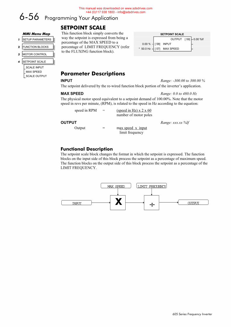
6-56 Programming Your Application
605 Series Frequency Inverter
SETPOINT SCALE This function block simply converts the way the setpoint is expressed from being a percentage of the MAX SPEED to a percentage of LIMIT FREQUENCY (refer to the FLUXING function block).
Functional Description The setpoint scale block changes the format in which the setpoint is expressed. The function blocks on the input side of this block process the setpoint as a percentage of maximum speed. The function blocks on the output side of this block process the setpoint as a percentage of the LIMIT FREQUENCY.
MMI Menu Map
1 SETUP PARAMETERS
2 FUNCTION BLOCKS
3 MOTOR CONTROL
4 SETPOINT SCALE
SCALE INPUT
MAX SPEED
SCALE OUTPUT
SETPOINT SCALE
OUTPUT [ 59] – 0.00 %lf
0.00 % – [ 58] INPUT –
* 50.0 Hz – [ 57] MAX SPEED –
Parameter Descriptions INPUT Range: -300.00 to 300.00 % The setpoint delivered by the re-wired function block portion of the inverter’s application.
MAX SPEED Range: 0.0 to 480.0 Hz The physical motor speed equivalent to a setpoint demand of 100.00%. Note that the motor speed in revs per minute, (RPM), is related to the speed in Hz according to the equation:
speed in RPM = (speed in Hz) x 2 x 60 number of motor poles
OUTPUT Range: xxx.xx %lf Output = max speed x input
limit frequency
÷
LIMIT FREQUENCY
X
MAX SPEED
INPUT OUTPUT
This manual was downloaded on www.sdsdrives.com +44 (0)117 938 1800 - [email protected]
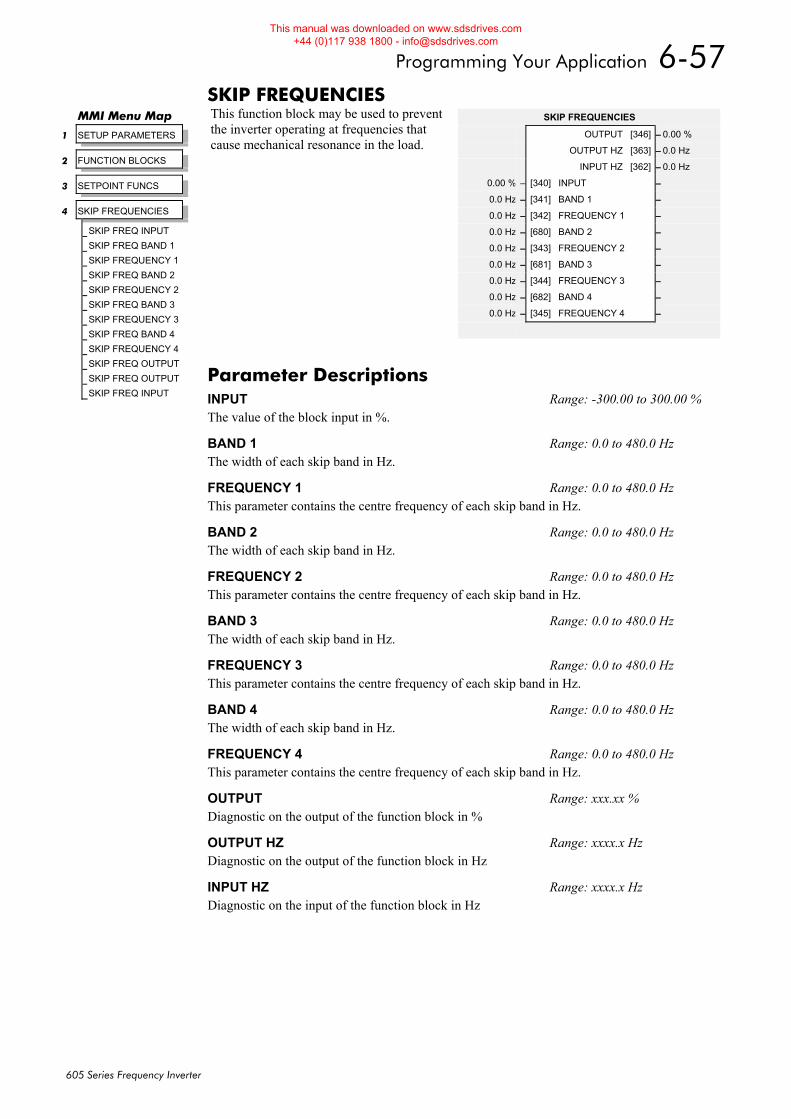
Programming Your Application 6-57
605 Series Frequency Inverter
SKIP FREQUENCIES This function block may be used to prevent the inverter operating at frequencies that cause mechanical resonance in the load.
MMI Menu Map
1 SETUP PARAMETERS
2 FUNCTION BLOCKS
3 SETPOINT FUNCS
4 SKIP FREQUENCIES
SKIP FREQ INPUT
SKIP FREQ BAND 1
SKIP FREQUENCY 1
SKIP FREQ BAND 2
SKIP FREQUENCY 2
SKIP FREQ BAND 3
SKIP FREQUENCY 3
SKIP FREQ BAND 4
SKIP FREQUENCY 4
SKIP FREQ OUTPUT
SKIP FREQ OUTPUT
SKIP FREQ INPUT
SKIP FREQUENCIES
OUTPUT [346] – 0.00 %
OUTPUT HZ [363] – 0.0 Hz
INPUT HZ [362] – 0.0 Hz
0.00 % – [340] INPUT –
0.0 Hz – [341] BAND 1 –
0.0 Hz – [342] FREQUENCY 1 –
0.0 Hz – [680] BAND 2 –
0.0 Hz – [343] FREQUENCY 2 –
0.0 Hz – [681] BAND 3 –
0.0 Hz – [344] FREQUENCY 3 –
0.0 Hz – [682] BAND 4 –
0.0 Hz – [345] FREQUENCY 4 –
Parameter Descriptions INPUT Range: -300.00 to 300.00 % The value of the block input in %.
BAND 1 Range: 0.0 to 480.0 Hz The width of each skip band in Hz.
FREQUENCY 1 Range: 0.0 to 480.0 Hz This parameter contains the centre frequency of each skip band in Hz.
BAND 2 Range: 0.0 to 480.0 Hz The width of each skip band in Hz.
FREQUENCY 2 Range: 0.0 to 480.0 Hz This parameter contains the centre frequency of each skip band in Hz.
BAND 3 Range: 0.0 to 480.0 Hz The width of each skip band in Hz.
FREQUENCY 3 Range: 0.0 to 480.0 Hz This parameter contains the centre frequency of each skip band in Hz.
BAND 4 Range: 0.0 to 480.0 Hz The width of each skip band in Hz.
FREQUENCY 4 Range: 0.0 to 480.0 Hz This parameter contains the centre frequency of each skip band in Hz.
OUTPUT Range: xxx.xx % Diagnostic on the output of the function block in %
OUTPUT HZ Range: xxxx.x Hz Diagnostic on the output of the function block in Hz
INPUT HZ Range: xxxx.x Hz Diagnostic on the input of the function block in Hz
This manual was downloaded on www.sdsdrives.com +44 (0)117 938 1800 - [email protected]
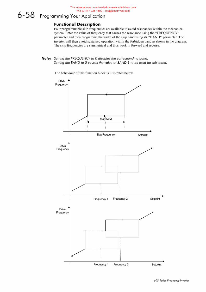
6-58 Programming Your Application
605 Series Frequency Inverter
Functional Description Four programmable skip frequencies are available to avoid resonances within the mechanical system. Enter the value of frequency that causes the resonance using the “FREQUENCY” parameter and then programme the width of the skip band using its “BAND” parameter. The inverter will then avoid sustained operation within the forbidden band as shown in the diagram. The skip frequencies are symmetrical and thus work in forward and reverse.
Note: Setting the FREQUENCY to 0 disables the corresponding band. Setting the BAND to 0 causes the value of BAND 1 to be used for this band.
The behaviour of this function block is illustrated below.
Setpoint
DriveFrequency
Frequency 1 Frequency 2
Skip band
Skip Frequency Setpoint
DriveFrequency
Setpoint
DriveFrequency
Frequency 1 Frequency 2
This manual was downloaded on www.sdsdrives.com +44 (0)117 938 1800 - [email protected]
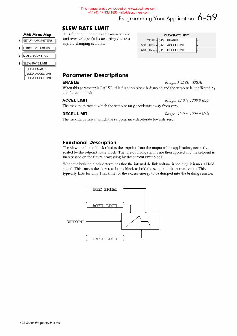
Programming Your Application 6-59
605 Series Frequency Inverter
SLEW RATE LIMIT This function block prevents over-current and over-voltage faults occurring due to a rapidly changing setpoint.
Functional Description The slew rate limits block obtains the setpoint from the output of the application, correctly scaled by the setpoint scale block. The rate of change limits are then applied and the setpoint is then passed on for future processing by the current limit block.
When the braking block determines that the internal dc link voltage is too high it issues a Hold signal. This causes the slew rate limits block to hold the setpoint at its current value. This typically lasts for only 1ms, time for the excess energy to be dumped into the braking resistor.
MMI Menu Map
1 SETUP PARAMETERS
2 FUNCTION BLOCKS
3 MOTOR CONTROL
4 SLEW RATE LIMIT
SLEW ENABLE
SLEW ACCEL LIMIT
SLEW DECEL LIMIT
SLEW RATE LIMIT
TRUE – [ 60] ENABLE –
500.0 Hz/s – [ 62] ACCEL LIMIT –
500.0 Hz/s – [ 61] DECEL LIMIT –
Parameter Descriptions ENABLE Range: FALSE / TRUE When this parameter is FALSE, this function block is disabled and the setpoint is unaffected by this function block.
ACCEL LIMIT Range: 12.0 to 1200.0 Hz/s The maximum rate at which the setpoint may accelerate away from zero.
DECEL LIMIT Range: 12.0 to 1200.0 Hz/s The maximum rate at which the setpoint may decelerate towards zero.
SETPOINT
DECEL LIMIT
ACCEL LIMIT
HOLD SIGNAL
This manual was downloaded on www.sdsdrives.com +44 (0)117 938 1800 - [email protected]
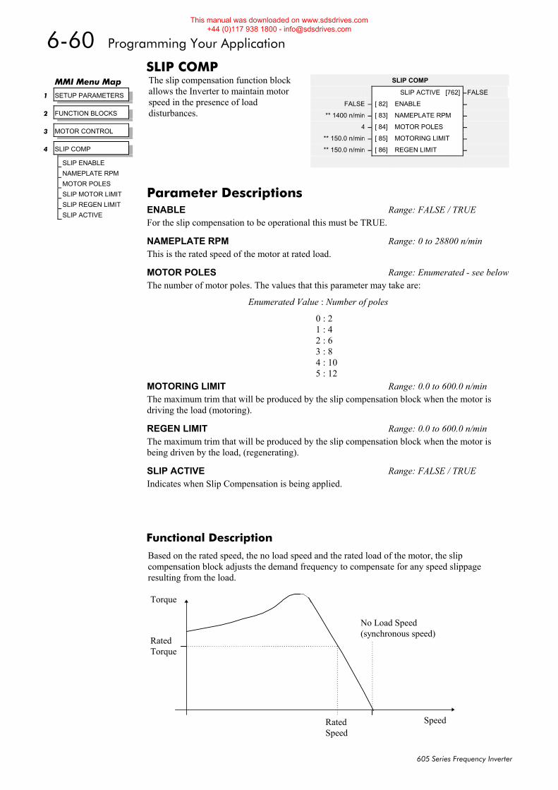
6-60 Programming Your Application
605 Series Frequency Inverter
SLIP COMP The slip compensation function block allows the Inverter to maintain motor speed in the presence of load disturbances.
Functional Description
Based on the rated speed, the no load speed and the rated load of the motor, the slip compensation block adjusts the demand frequency to compensate for any speed slippage resulting from the load.
MMI Menu Map
1 SETUP PARAMETERS
2 FUNCTION BLOCKS
3 MOTOR CONTROL
4 SLIP COMP
SLIP ENABLE
NAMEPLATE RPM
MOTOR POLES
SLIP MOTOR LIMIT
SLIP REGEN LIMIT
SLIP ACTIVE
SLIP COMP
SLIP ACTIVE [762] –FALSE
FALSE – [ 82] ENABLE –
** 1400 n/min – [ 83] NAMEPLATE RPM –
4 – [ 84] MOTOR POLES –
** 150.0 n/min – [ 85] MOTORING LIMIT –
** 150.0 n/min – [ 86] REGEN LIMIT –
Parameter Descriptions ENABLE Range: FALSE / TRUE For the slip compensation to be operational this must be TRUE.
NAMEPLATE RPM Range: 0 to 28800 n/min This is the rated speed of the motor at rated load.
MOTOR POLES Range: Enumerated - see belowThe number of motor poles. The values that this parameter may take are:
Enumerated Value : Number of poles
0 : 2 1 : 4 2 : 6 3 : 8 4 : 10 5 : 12
MOTORING LIMIT Range: 0.0 to 600.0 n/min The maximum trim that will be produced by the slip compensation block when the motor is driving the load (motoring).
REGEN LIMIT Range: 0.0 to 600.0 n/min The maximum trim that will be produced by the slip compensation block when the motor is being driven by the load, (regenerating).
SLIP ACTIVE Range: FALSE / TRUE Indicates when Slip Compensation is being applied.
SpeedRatedSpeed
No Load Speed(synchronous speed)
RatedTorque
Torque
This manual was downloaded on www.sdsdrives.com +44 (0)117 938 1800 - [email protected]

Programming Your Application 6-61
605 Series Frequency Inverter
STABILISATION Enabling this function alleviates the problem of unstable running in induction motors. This can be experienced at approximately half full speed, and under low load conditions.
MMI Menu Map
1 SETUP PARAMETERS
2 FUNCTION BLOCKS
3 MOTOR CONTROL
4 STABILISATION
STB ENABLE
STABILISATION
TRUE – [128] ENABLE –
Parameter Descriptions ENABLE Range: FALSE / TRUE Enables (or disables) the stabilisation function.
This manual was downloaded on www.sdsdrives.com +44 (0)117 938 1800 - [email protected]
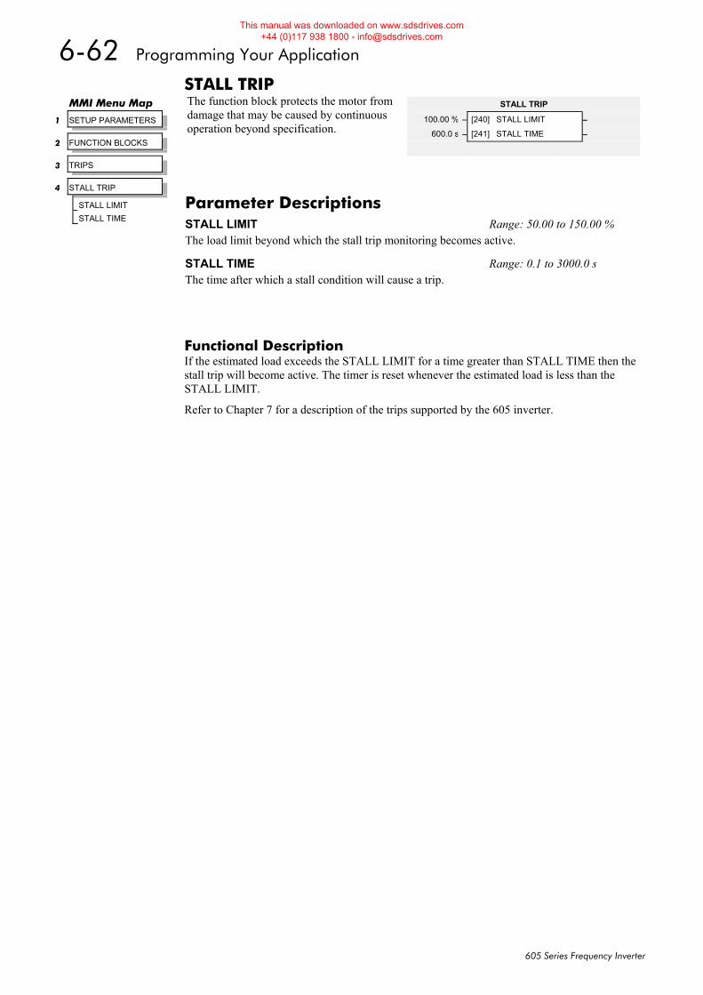
6-62 Programming Your Application
605 Series Frequency Inverter
STALL TRIP The function block protects the motor from damage that may be caused by continuous operation beyond specification.
Functional Description If the estimated load exceeds the STALL LIMIT for a time greater than STALL TIME then the stall trip will become active. The timer is reset whenever the estimated load is less than the STALL LIMIT.
Refer to Chapter 7 for a description of the trips supported by the 605 inverter.
MMI Menu Map
1 SETUP PARAMETERS
2 FUNCTION BLOCKS
3 TRIPS
4 STALL TRIP
STALL LIMIT
STALL TIME
STALL TRIP
100.00 % – [240] STALL LIMIT –
600.0 s – [241] STALL TIME –
Parameter Descriptions STALL LIMIT Range: 50.00 to 150.00 % The load limit beyond which the stall trip monitoring becomes active.
STALL TIME Range: 0.1 to 3000.0 s The time after which a stall condition will cause a trip.
This manual was downloaded on www.sdsdrives.com +44 (0)117 938 1800 - [email protected]
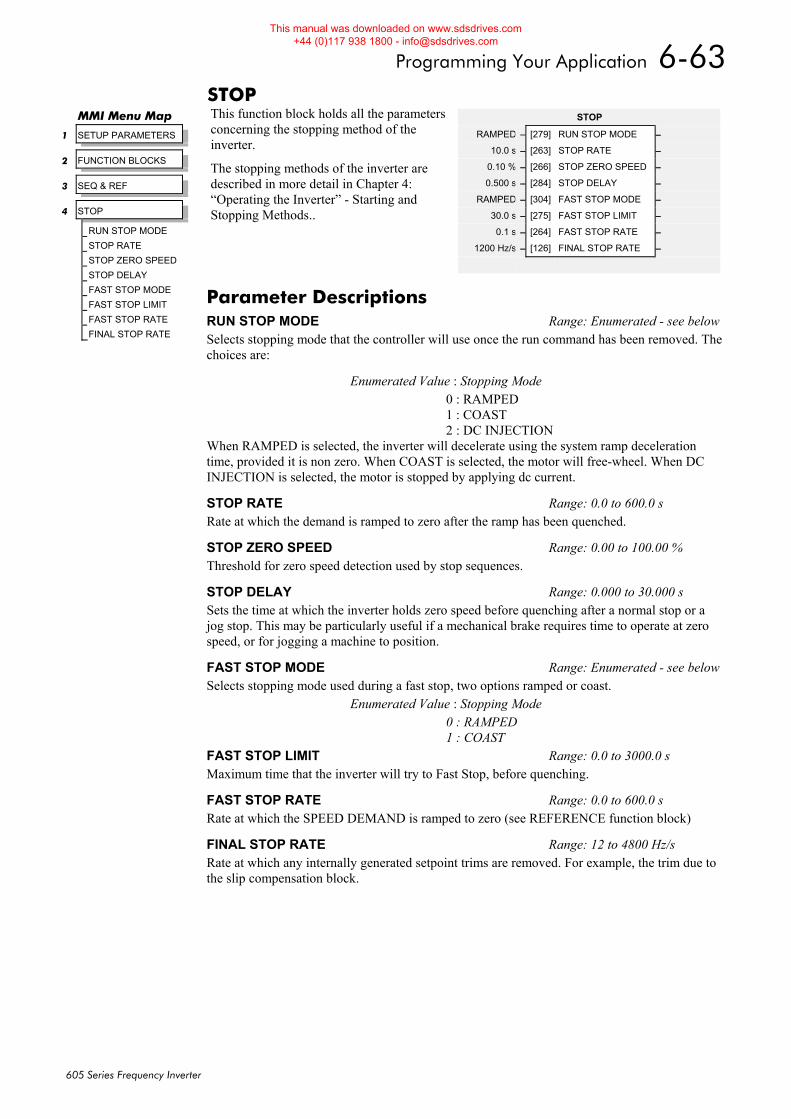
Programming Your Application 6-63
605 Series Frequency Inverter
STOP This function block holds all the parameters concerning the stopping method of the inverter.
The stopping methods of the inverter are described in more detail in Chapter 4: “Operating the Inverter” - Starting and Stopping Methods..
MMI Menu Map
1 SETUP PARAMETERS
2 FUNCTION BLOCKS
3 SEQ & REF
4 STOP
RUN STOP MODE
STOP RATE
STOP ZERO SPEED
STOP DELAY
FAST STOP MODE
FAST STOP LIMIT
FAST STOP RATE
FINAL STOP RATE
STOP
RAMPED – [279] RUN STOP MODE –
10.0 s – [263] STOP RATE –
0.10 % – [266] STOP ZERO SPEED –
0.500 s – [284] STOP DELAY –
RAMPED – [304] FAST STOP MODE –
30.0 s – [275] FAST STOP LIMIT –
0.1 s – [264] FAST STOP RATE –
1200 Hz/s – [126] FINAL STOP RATE –
Parameter Descriptions RUN STOP MODE Range: Enumerated - see belowSelects stopping mode that the controller will use once the run command has been removed. The choices are:
Enumerated Value : Stopping Mode 0 : RAMPED 1 : COAST 2 : DC INJECTION
When RAMPED is selected, the inverter will decelerate using the system ramp deceleration time, provided it is non zero. When COAST is selected, the motor will free-wheel. When DC INJECTION is selected, the motor is stopped by applying dc current.
STOP RATE Range: 0.0 to 600.0 s Rate at which the demand is ramped to zero after the ramp has been quenched.
STOP ZERO SPEED Range: 0.00 to 100.00 % Threshold for zero speed detection used by stop sequences.
STOP DELAY Range: 0.000 to 30.000 s Sets the time at which the inverter holds zero speed before quenching after a normal stop or a jog stop. This may be particularly useful if a mechanical brake requires time to operate at zero speed, or for jogging a machine to position.
FAST STOP MODE Range: Enumerated - see belowSelects stopping mode used during a fast stop, two options ramped or coast.
Enumerated Value : Stopping Mode 0 : RAMPED 1 : COAST
FAST STOP LIMIT Range: 0.0 to 3000.0 s Maximum time that the inverter will try to Fast Stop, before quenching.
FAST STOP RATE Range: 0.0 to 600.0 s Rate at which the SPEED DEMAND is ramped to zero (see REFERENCE function block)
FINAL STOP RATE Range: 12 to 4800 Hz/s Rate at which any internally generated setpoint trims are removed. For example, the trim due to the slip compensation block.
This manual was downloaded on www.sdsdrives.com +44 (0)117 938 1800 - [email protected]
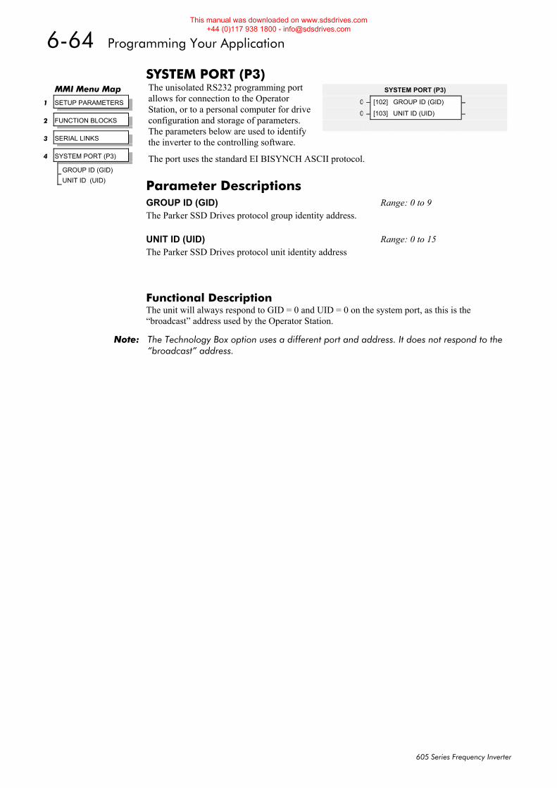
6-64 Programming Your Application
605 Series Frequency Inverter
SYSTEM PORT (P3) The unisolated RS232 programming port allows for connection to the Operator Station, or to a personal computer for drive configuration and storage of parameters. The parameters below are used to identify the inverter to the controlling software.
The port uses the standard EI BISYNCH ASCII protocol.
Functional Description The unit will always respond to GID = 0 and UID = 0 on the system port, as this is the “broadcast” address used by the Operator Station.
Note: The Technology Box option uses a different port and address. It does not respond to the “broadcast” address.
SYSTEM PORT (P3)
0 – [102] GROUP ID (GID) –
0 – [103] UNIT ID (UID) –
MMI Menu Map
1 SETUP PARAMETERS
2 FUNCTION BLOCKS
3 SERIAL LINKS
4 SYSTEM PORT (P3)
GROUP ID (GID)
UNIT ID (UID) Parameter Descriptions GROUP ID (GID) Range: 0 to 9 The Parker SSD Drives protocol group identity address. UNIT ID (UID) Range: 0 to 15 The Parker SSD Drives protocol unit identity address
This manual was downloaded on www.sdsdrives.com +44 (0)117 938 1800 - [email protected]
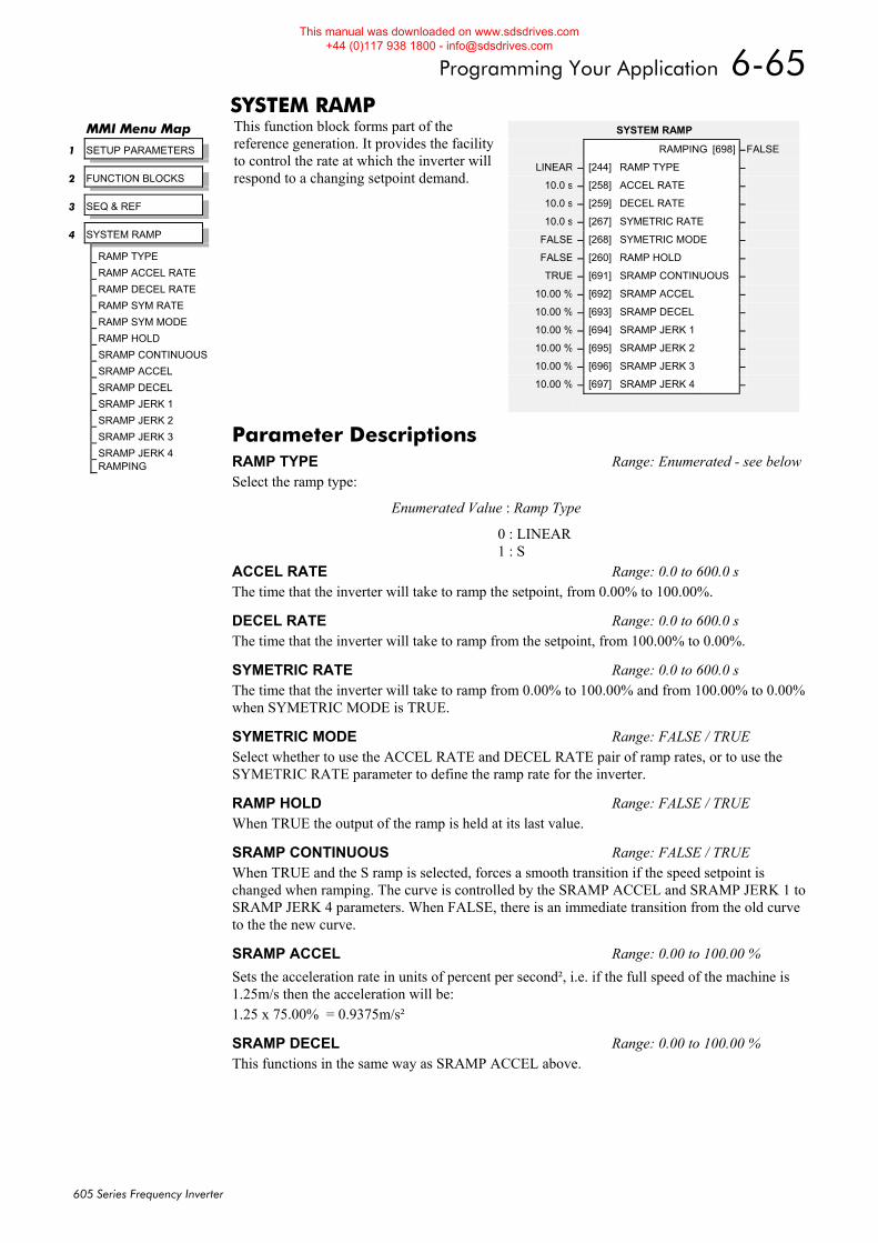
Programming Your Application 6-65
605 Series Frequency Inverter
SYSTEM RAMP This function block forms part of the reference generation. It provides the facility to control the rate at which the inverter will respond to a changing setpoint demand.
MMI Menu Map
1 SETUP PARAMETERS
2 FUNCTION BLOCKS
3 SEQ & REF
4 SYSTEM RAMP
RAMP TYPE
RAMP ACCEL RATE
RAMP DECEL RATE
RAMP SYM RATE
RAMP SYM MODE
RAMP HOLD
SRAMP CONTINUOUS
SRAMP ACCEL
SRAMP DECEL
SRAMP JERK 1
SRAMP JERK 2
SRAMP JERK 3
SRAMP JERK 4 RAMPING
SYSTEM RAMP
RAMPING [698] –FALSE
LINEAR – [244] RAMP TYPE –
10.0 s – [258] ACCEL RATE –
10.0 s – [259] DECEL RATE –
10.0 s – [267] SYMETRIC RATE –
FALSE – [268] SYMETRIC MODE –
FALSE – [260] RAMP HOLD –
TRUE – [691] SRAMP CONTINUOUS –
10.00 % – [692] SRAMP ACCEL –
10.00 % – [693] SRAMP DECEL –
10.00 % – [694] SRAMP JERK 1 –
10.00 % – [695] SRAMP JERK 2 –
10.00 % – [696] SRAMP JERK 3 –
10.00 % – [697] SRAMP JERK 4 –
Parameter Descriptions RAMP TYPE Range: Enumerated - see belowSelect the ramp type:
Enumerated Value : Ramp Type
0 : LINEAR 1 : S
ACCEL RATE Range: 0.0 to 600.0 s The time that the inverter will take to ramp the setpoint, from 0.00% to 100.00%.
DECEL RATE Range: 0.0 to 600.0 s The time that the inverter will take to ramp from the setpoint, from 100.00% to 0.00%.
SYMETRIC RATE Range: 0.0 to 600.0 s The time that the inverter will take to ramp from 0.00% to 100.00% and from 100.00% to 0.00% when SYMETRIC MODE is TRUE.
SYMETRIC MODE Range: FALSE / TRUE Select whether to use the ACCEL RATE and DECEL RATE pair of ramp rates, or to use the SYMETRIC RATE parameter to define the ramp rate for the inverter.
RAMP HOLD Range: FALSE / TRUE When TRUE the output of the ramp is held at its last value.
SRAMP CONTINUOUS Range: FALSE / TRUE When TRUE and the S ramp is selected, forces a smooth transition if the speed setpoint is changed when ramping. The curve is controlled by the SRAMP ACCEL and SRAMP JERK 1 to SRAMP JERK 4 parameters. When FALSE, there is an immediate transition from the old curve to the the new curve.
SRAMP ACCEL Range: 0.00 to 100.00 % Sets the acceleration rate in units of percent per second², i.e. if the full speed of the machine is 1.25m/s then the acceleration will be: 1.25 x 75.00% = 0.9375m/s²
SRAMP DECEL Range: 0.00 to 100.00 % This functions in the same way as SRAMP ACCEL above.
This manual was downloaded on www.sdsdrives.com +44 (0)117 938 1800 - [email protected]
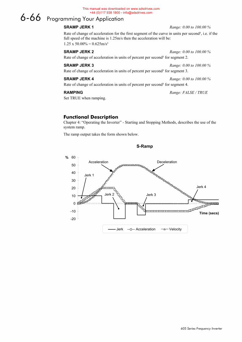
6-66 Programming Your Application
605 Series Frequency Inverter
Functional Description Chapter 4: “Operating the Inverter” - Starting and Stopping Methods, describes the use of the system ramp.
The ramp output takes the form shown below.
S-Ramp
-20
-10
0
10
20
30
40
50
60
Time (secs)
%
Jerk Acceleration Velocity
Jerk 3
Jerk 4
Jerk 2
Jerk 1
Acceleration Deceleration
SRAMP JERK 1 Range: 0.00 to 100.00 % Rate of change of acceleration for the first segment of the curve in units per second³, i.e. if the full speed of the machine is 1.25m/s then the acceleration will be: 1.25 x 50.00% = 0.625m/s³
SRAMP JERK 2 Range: 0.00 to 100.00 % Rate of change of acceleration in units of percent per second³ for segment 2.
SRAMP JERK 3 Range: 0.00 to 100.00 % Rate of change of acceleration in units of percent per second³ for segment 3.
SRAMP JERK 4 Range: 0.00 to 100.00 % Rate of change of acceleration in units of percent per second³ for segment 4.
RAMPING Range: FALSE / TRUE Set TRUE when ramping.
This manual was downloaded on www.sdsdrives.com +44 (0)117 938 1800 - [email protected]
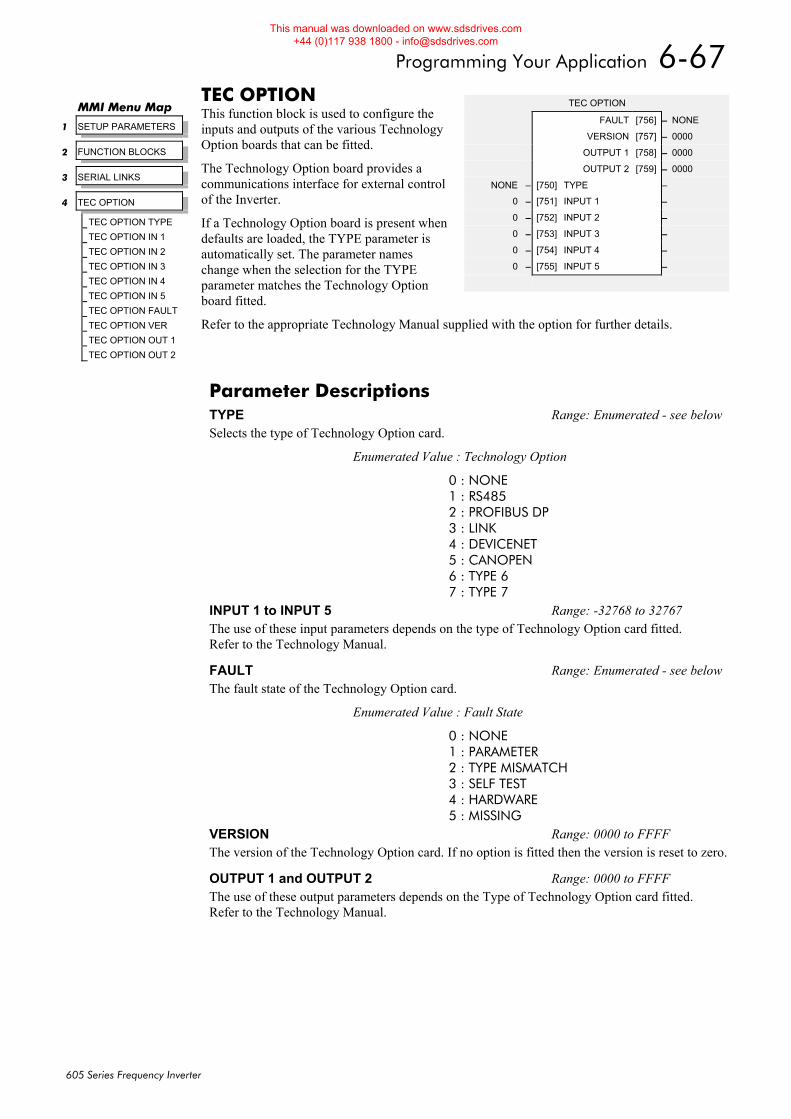
Programming Your Application 6-67
605 Series Frequency Inverter
TEC OPTION This function block is used to configure the inputs and outputs of the various Technology Option boards that can be fitted.
The Technology Option board provides a communications interface for external control of the Inverter.
If a Technology Option board is present when defaults are loaded, the TYPE parameter is automatically set. The parameter names change when the selection for the TYPE parameter matches the Technology Option board fitted.
Refer to the appropriate Technology Manual supplied with the option for further details.
MMI Menu Map
1 SETUP PARAMETERS
2 FUNCTION BLOCKS
3 SERIAL LINKS
4 TEC OPTION
TEC OPTION TYPE
TEC OPTION IN 1
TEC OPTION IN 2
TEC OPTION IN 3
TEC OPTION IN 4
TEC OPTION IN 5
TEC OPTION FAULT
TEC OPTION VER
TEC OPTION OUT 1
TEC OPTION OUT 2
TEC OPTION
FAULT [756] – NONE
VERSION [757] – 0000
OUTPUT 1 [758] – 0000
OUTPUT 2 [759] – 0000
NONE – [750] TYPE –
0 – [751] INPUT 1 –
0 – [752] INPUT 2 –
0 – [753] INPUT 3 –
0 – [754] INPUT 4 –
0 – [755] INPUT 5 –
Parameter Descriptions TYPE Range: Enumerated - see belowSelects the type of Technology Option card.
Enumerated Value : Technology Option
0 : NONE 1 : RS485 2 : PROFIBUS DP 3 : LINK 4 : DEVICENET 5 : CANOPEN 6 : TYPE 6 7 : TYPE 7
INPUT 1 to INPUT 5 Range: -32768 to 32767 The use of these input parameters depends on the type of Technology Option card fitted. Refer to the Technology Manual.
FAULT Range: Enumerated - see belowThe fault state of the Technology Option card.
Enumerated Value : Fault State
0 : NONE 1 : PARAMETER 2 : TYPE MISMATCH 3 : SELF TEST 4 : HARDWARE 5 : MISSING
VERSION Range: 0000 to FFFF The version of the Technology Option card. If no option is fitted then the version is reset to zero.
OUTPUT 1 and OUTPUT 2 Range: 0000 to FFFF The use of these output parameters depends on the Type of Technology Option card fitted. Refer to the Technology Manual.
This manual was downloaded on www.sdsdrives.com +44 (0)117 938 1800 - [email protected]
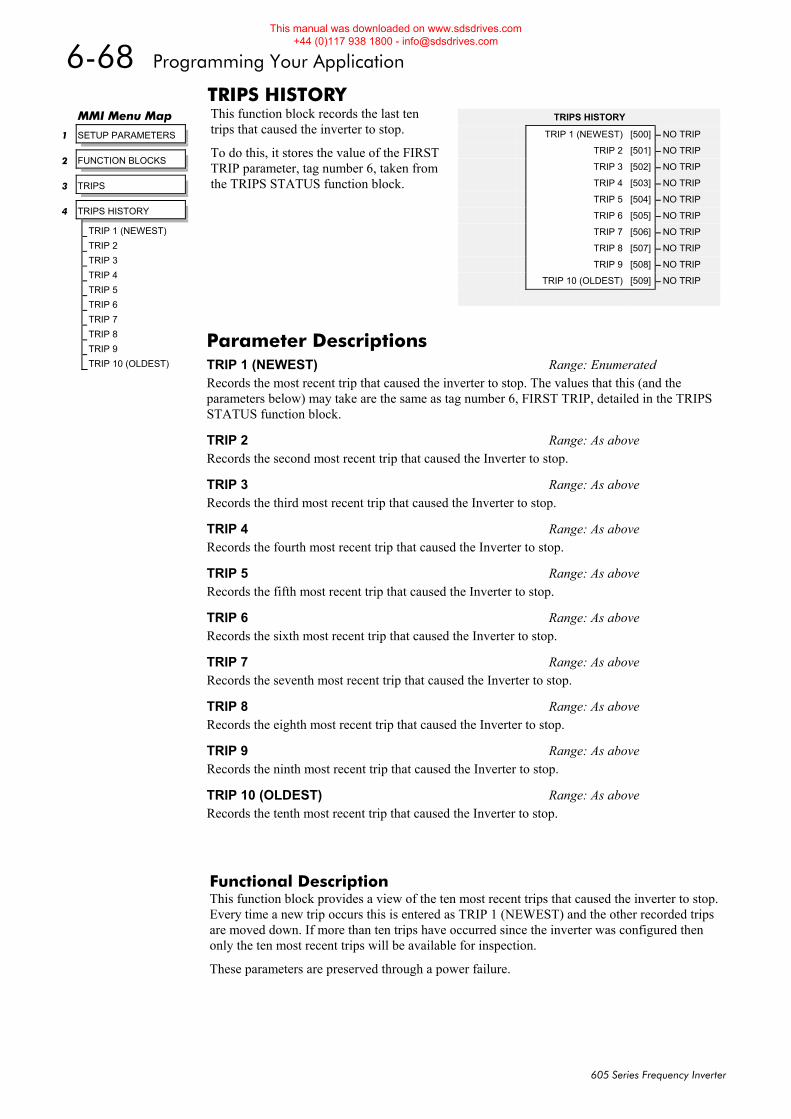
6-68 Programming Your Application
605 Series Frequency Inverter
TRIPS HISTORY This function block records the last ten trips that caused the inverter to stop.
To do this, it stores the value of the FIRST TRIP parameter, tag number 6, taken from the TRIPS STATUS function block.
Functional Description This function block provides a view of the ten most recent trips that caused the inverter to stop. Every time a new trip occurs this is entered as TRIP 1 (NEWEST) and the other recorded trips are moved down. If more than ten trips have occurred since the inverter was configured then only the ten most recent trips will be available for inspection.
These parameters are preserved through a power failure.
MMI Menu Map
1 SETUP PARAMETERS
2 FUNCTION BLOCKS
3 TRIPS
4 TRIPS HISTORY
TRIP 1 (NEWEST)
TRIP 2
TRIP 3
TRIP 4
TRIP 5
TRIP 6
TRIP 7
TRIP 8
TRIP 9
TRIP 10 (OLDEST)
TRIPS HISTORY
TRIP 1 (NEWEST) [500] – NO TRIP
TRIP 2 [501] – NO TRIP
TRIP 3 [502] – NO TRIP
TRIP 4 [503] – NO TRIP
TRIP 5 [504] – NO TRIP
TRIP 6 [505] – NO TRIP
TRIP 7 [506] – NO TRIP
TRIP 8 [507] – NO TRIP
TRIP 9 [508] – NO TRIP
TRIP 10 (OLDEST) [509] – NO TRIP
Parameter Descriptions TRIP 1 (NEWEST) Range: Enumerated Records the most recent trip that caused the inverter to stop. The values that this (and the parameters below) may take are the same as tag number 6, FIRST TRIP, detailed in the TRIPS STATUS function block.
TRIP 2 Range: As above Records the second most recent trip that caused the Inverter to stop.
TRIP 3 Range: As above Records the third most recent trip that caused the Inverter to stop.
TRIP 4 Range: As above Records the fourth most recent trip that caused the Inverter to stop.
TRIP 5 Range: As above Records the fifth most recent trip that caused the Inverter to stop.
TRIP 6 Range: As above Records the sixth most recent trip that caused the Inverter to stop.
TRIP 7 Range: As above Records the seventh most recent trip that caused the Inverter to stop.
TRIP 8 Range: As above Records the eighth most recent trip that caused the Inverter to stop.
TRIP 9 Range: As above Records the ninth most recent trip that caused the Inverter to stop.
TRIP 10 (OLDEST) Range: As above Records the tenth most recent trip that caused the Inverter to stop.
This manual was downloaded on www.sdsdrives.com +44 (0)117 938 1800 - [email protected]
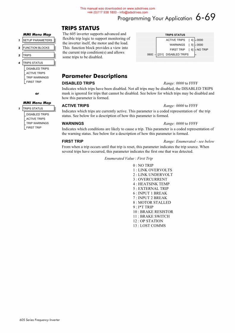
Programming Your Application 6-69
605 Series Frequency Inverter
TRIPS STATUS The 605 inverter supports advanced and flexible trip logic to support monitoring of the inverter itself, the motor and the load. This function block provides a view into the current trip condition(s) and allows some trips to be disabled.
MMI Menu Map
1 SETUP PARAMETERS
2 FUNCTION BLOCKS
3 TRIPS
4 TRIPS STATUS
DISABLED TRIPS
ACTIVE TRIPS
TRIP WARNINGS
FIRST TRIP
TRIPS STATUS
ACTIVE TRIPS [ 4] – 0000
WARNINGS [ 5] – 0000
FIRST TRIP [ 6] – NO TRIP
0600 – [231] DISABLED TRIPS –
Parameter Descriptions DISABLED TRIPS Range: 0000 to FFFF Indicates which trips have been disabled. Not all trips may be disabled, the DISABLED TRIPS mask is ignored for trips that cannot be disabled. See below for which trips may be disabled and how this parameter is formed.
ACTIVE TRIPS Range: 0000 to FFFF Indicates which trips are currently active. This parameter is a coded representation of the trip status. See below for a description of how this parameter is formed.
WARNINGS Range: 0000 to FFFF Indicates which conditions are likely to cause a trip. This parameter is a coded representation of the warning status. See below for a description of how this parameter is formed.
FIRST TRIP Range: Enumerated - see belowFrom when a trip occurs until that trip is reset, this parameter indicates the trip source. When several trips have occurred, this parameter indicates the first one that was detected.
Enumerated Value : First Trip
0 : NO TRIP 1 : LINK OVERVOLTS 2 : LINK UNDERVOLT 3 : OVERCURRENT 4 : HEATSINK TEMP 5 : EXTERNAL TRIP 6 : INPUT 1 BREAK 7 : INPUT 2 BREAK 8 : MOTOR STALLED 9 : I*T TRIP 10 : BRAKE RESISTOR 11 : BRAKE SWITCH 12 : OP STATION 13 : LOST COMMS
or
MMI Menu Map
1 TRIPS STATUS
DISABLED TRIPS
ACTIVE TRIPS
TRIP WARNINGS
FIRST TRIP
This manual was downloaded on www.sdsdrives.com +44 (0)117 938 1800 - [email protected]
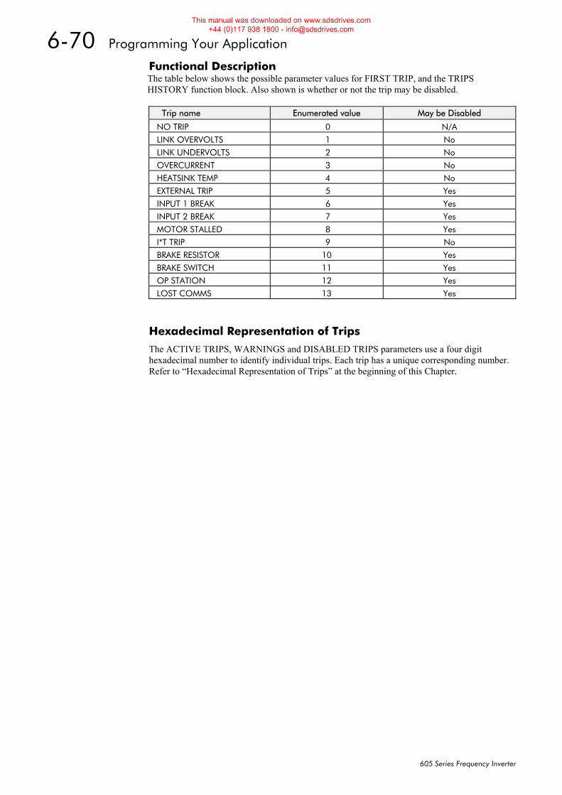
6-70 Programming Your Application
605 Series Frequency Inverter
Functional Description The table below shows the possible parameter values for FIRST TRIP, and the TRIPS HISTORY function block. Also shown is whether or not the trip may be disabled.
Trip name Enumerated value May be Disabled
NO TRIP 0 N/A
LINK OVERVOLTS 1 No
LINK UNDERVOLTS 2 No
OVERCURRENT 3 No
HEATSINK TEMP 4 No
EXTERNAL TRIP 5 Yes
INPUT 1 BREAK 6 Yes
INPUT 2 BREAK 7 Yes
MOTOR STALLED 8 Yes
I*T TRIP 9 No
BRAKE RESISTOR 10 Yes
BRAKE SWITCH 11 Yes
OP STATION 12 Yes
LOST COMMS 13 Yes
Hexadecimal Representation of Trips
The ACTIVE TRIPS, WARNINGS and DISABLED TRIPS parameters use a four digit hexadecimal number to identify individual trips. Each trip has a unique corresponding number. Refer to “Hexadecimal Representation of Trips” at the beginning of this Chapter.
This manual was downloaded on www.sdsdrives.com +44 (0)117 938 1800 - [email protected]
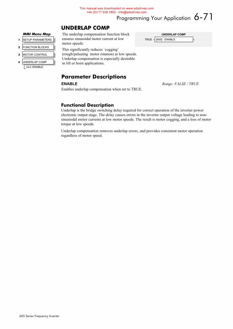
Programming Your Application 6-71
605 Series Frequency Inverter
UNDERLAP COMP The underlap compensation function block ensures sinusoidal motor current at low motor speeds. This significantly reduces `cogging’ (rough/pulsating motor rotation) at low speeds. Underlap compensation is especially desirable in lift or hoist applications.
Functional Description Underlap is the bridge switching delay required for correct operation of the inverter power electronic output stage. The delay causes errors in the inverter output voltage leading to non-sinusiodal motor currents at low motor speeds. The result is motor cogging, and a loss of motor torque at low speeds.
Underlap compensation removes underlap errors, and provides consistent motor operation regardless of motor speed.
MMI Menu Map
1 SETUP PARAMETERS
2 FUNCTION BLOCKS
3 MOTOR CONTROL
4 UNDERLAP COMP
ULC ENABLE
UNDERLAP COMP
TRUE – [600] ENABLE –
Parameter Descriptions ENABLE Range: FALSE / TRUE Enables underlap compensation when set to TRUE.
This manual was downloaded on www.sdsdrives.com +44 (0)117 938 1800 - [email protected]
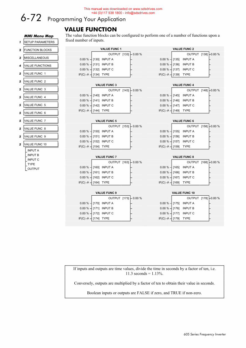
6-72 Programming Your Application
605 Series Frequency Inverter
VALUE FUNCTION The value function blocks can be configured to perform one of a number of functions upon a fixed number of inputs.
MMI Menu Map
1 SETUP PARAMETERS
2 FUNCTION BLOCKS
3 MISCELLANEOUS
4 VALUE FUNCTIONS
5 VALUE FUNC 1
5 VALUE FUNC 2
5 VALUE FUNC 3
5 VALUE FUNC 4
5 VALUE FUNC 5
5 VALUE FUNC 6
5 VALUE FUNC 7
5 VALUE FUNC 8
5 VALUE FUNC 9
5 VALUE FUNC 10
INPUT A
INPUT B
INPUT C
TYPE
OUTPUT
VALUE FUNC 1
OUTPUT [133] – 0.00 %
0.00 % – [130] INPUT A –
0.00 % – [131] INPUT B –
0.00 % – [132] INPUT C –
IF(C) -A – [134] TYPE –
VALUE FUNC 3
OUTPUT [143] – 0.00 %
0.00 % – [140] INPUT A –
0.00 % – [141] INPUT B –
0.00 % – [142] INPUT C –
IF(C) -A – [144] TYPE –
VALUE FUNC 5
OUTPUT [153] – 0.00 %
0.00 % – [150] INPUT A –
0.00 % – [151] INPUT B –
0.00 % – [152] INPUT C –
IF(C) -A – [154] TYPE –
VALUE FUNC 7
OUTPUT [163] – 0.00 %
0.00 % – [160] INPUT A –
0.00 % – [161] INPUT B –
0.00 % – [162] INPUT C –
IF(C) -A – [164] TYPE –
VALUE FUNC 9
OUTPUT [173] – 0.00 %
0.00 % – [170] INPUT A –
0.00 % – [171] INPUT B –
0.00 % – [172] INPUT C –
IF(C) -A – [174] TYPE –
VALUE FUNC 2
OUTPUT [138] –0.00 %
0.00 % – [135] INPUT A –
0.00 % – [136] INPUT B –
0.00 % – [137] INPUT C –
IF(C) -A – [139] TYPE –
VALUE FUNC 4
OUTPUT [148] –0.00 %
0.00 % – [145] INPUT A –
0.00 % – [146] INPUT B –
0.00 % – [147] INPUT C –
IF(C) -A – [149] TYPE –
VALUE FUNC 6
OUTPUT [158] –0.00 %
0.00 % – [155] INPUT A –
0.00 % – [156] INPUT B –
0.00 % – [157] INPUT C –
IF(C) -A – [159] TYPE –
VALUE FUNC 8
OUTPUT [168] –0.00 %
0.00 % – [165] INPUT A –
0.00 % – [166] INPUT B –
0.00 % – [167] INPUT C –
IF(C) -A – [169] TYPE –
VALUE FUNC 10
OUTPUT [178] –0.00 %
0.00 % – [175] INPUT A –
0.00 % – [176] INPUT B –
0.00 % – [177] INPUT C –
IF(C) -A – [179] TYPE –
If inputs and outputs are time values, divide the time in seconds by a factor of ten, i.e. 11.3 seconds = 1.13%.
Conversely, outputs are multiplied by a factor of ten to obtain their value in seconds.
Boolean inputs or outputs are FALSE if zero, and TRUE if non-zero.
This manual was downloaded on www.sdsdrives.com +44 (0)117 938 1800 - [email protected]
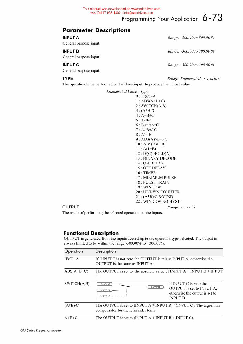
Programming Your Application 6-73
605 Series Frequency Inverter
Functional Description OUTPUT is generated from the inputs according to the operation type selected. The output is always limited to be within the range -300.00% to +300.00%.
Operation Description
IF(C) -A If INPUT C is not zero the OUTPUT is minus INPUT A, otherwise the OUTPUT is the same as INPUT A.
ABS(A+B+C) The OUTPUT is set to the absolute value of INPUT A + INPUT B + INPUT C.
SWITCH(A,B) OUTPUT
INPUT A
INPUT B
INPUT C
If INPUT C is zero the OUTPUT is set to INPUT A, otherwise the output is set to INPUT B
(A*B)/C The OUTPUT is set to (INPUT A * INPUT B) / (INPUT C). The algorithm compensates for the remainder term.
A+B+C The OUTPUT is set to (INPUT A + INPUT B + INPUT C).
Parameter Descriptions INPUT A Range: -300.00 to 300.00 % General purpose input.
INPUT B Range: -300.00 to 300.00 % General purpose input.
INPUT C Range: -300.00 to 300.00 % General purpose input.
TYPE Range: Enumerated - see belowThe operation to be performed on the three inputs to produce the output value.
Enumerated Value : Type 0 : IF(C) -A 1 : ABS(A+B+C) 2 : SWITCH(A,B) 3 : (A*B)/C 4 : A+B+C 5 : A-B-C 6 : B<=A<=C 7 : A>B+/-C 8 : A>=B 9 : ABS(A)>B+/-C 10 : ABS(A)>=B 11 : A(1+B) 12 : IF(C) HOLD(A) 13 : BINARY DECODE 14 : ON DELAY 15 : OFF DELAY 16 : TIMER 17 : MINIMUM PULSE 18 : PULSE TRAIN 19 : WINDOW 20 : UP/DWN COUNTER 21 : (A*B)/C ROUND 22 : WINDOW NO HYST
OUTPUT Range: xxx.xx % The result of performing the selected operation on the inputs.
This manual was downloaded on www.sdsdrives.com +44 (0)117 938 1800 - [email protected]
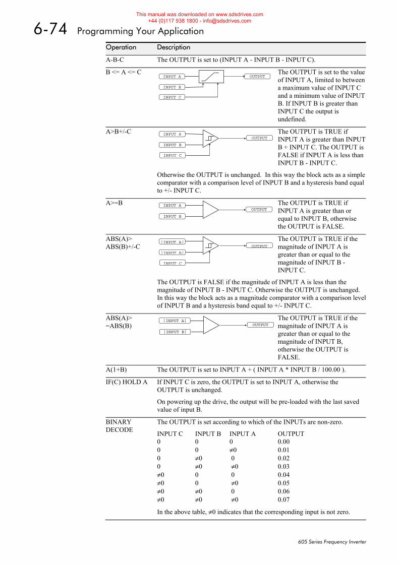
6-74 Programming Your Application
605 Series Frequency Inverter
Operation Description
A-B-C The OUTPUT is set to (INPUT A - INPUT B - INPUT C).
B <= A <= C OUTPUTINPUT A
INPUT B
INPUT C
The OUTPUT is set to the value of INPUT A, limited to between a maximum value of INPUT C and a minimum value of INPUT B. If INPUT B is greater than INPUT C the output is undefined.
A>B+/-C OUTPUT
INPUT A
INPUT B
INPUT C
The OUTPUT is TRUE if INPUT A is greater than INPUT B + INPUT C. The OUTPUT is FALSE if INPUT A is less than INPUT B - INPUT C.
Otherwise the OUTPUT is unchanged. In this way the block acts as a simple comparator with a comparison level of INPUT B and a hysteresis band equal to +/- INPUT C.
A>=B OUTPUT
INPUT A
INPUT B
The OUTPUT is TRUE if INPUT A is greater than or equal to INPUT B, otherwise the OUTPUT is FALSE.
ABS(A)> ABS(B)+/-C OUTPUT
|INPUT A|
|INPUT B|
INPUT C
The OUTPUT is TRUE if the magnitude of INPUT A is greater than or equal to the magnitude of INPUT B - INPUT C.
The OUTPUT is FALSE if the magnitude of INPUT A is less than the magnitude of INPUT B - INPUT C. Otherwise the OUTPUT is unchanged. In this way the block acts as a magnitude comparator with a comparison level of INPUT B and a hysteresis band equal to +/- INPUT C.
ABS(A)> =ABS(B) OUTPUT
|INPUT A|
|INPUT B|
The OUTPUT is TRUE if the magnitude of INPUT A is greater than or equal to the magnitude of INPUT B, otherwise the OUTPUT is FALSE.
A(1+B) The OUTPUT is set to INPUT A + ( INPUT A * INPUT B / 100.00 ).
IF(C) HOLD A If INPUT C is zero, the OUTPUT is set to INPUT A, otherwise the OUTPUT is unchanged.
On powering up the drive, the output will be pre-loaded with the last saved value of input B.
BINARY DECODE
The OUTPUT is set according to which of the INPUTs are non-zero.
INPUT C INPUT B INPUT A OUTPUT 0 0 0 0.00 0 0 ≠0 0.01 0 ≠0 0 0.02 0 ≠0 ≠0 0.03 ≠0 0 0 0.04 ≠0 0 ≠0 0.05 ≠0 ≠0 0 0.06 ≠0 ≠0 ≠0 0.07
In the above table, ≠0 indicates that the corresponding input is not zero.
This manual was downloaded on www.sdsdrives.com +44 (0)117 938 1800 - [email protected]
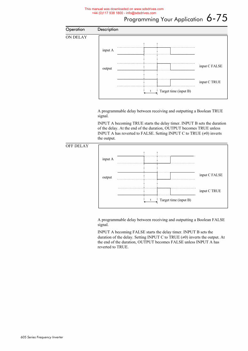
Programming Your Application 6-75
605 Series Frequency Inverter
Operation Description
ON DELAY
A programmable delay between receiving and outputting a Boolean TRUE signal.
INPUT A becoming TRUE starts the delay timer. INPUT B sets the duration of the delay. At the end of the duration, OUTPUT becomes TRUE unless INPUT A has reverted to FALSE. Setting INPUT C to TRUE (≠0) inverts the output.
OFF DELAY
A programmable delay between receiving and outputting a Boolean FALSE signal.
INPUT A becoming FALSE starts the delay timer. INPUT B sets the duration of the delay. Setting INPUT C to TRUE (≠0) inverts the output. At the end of the duration, OUTPUT becomes FALSE unless INPUT A has reverted to TRUE.
input A
output input C FALSE
input C TRUE
Target time (input B)t
input A
output input C FALSE
input C TRUE
Target time (input B)t
This manual was downloaded on www.sdsdrives.com +44 (0)117 938 1800 - [email protected]
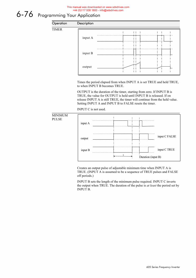
6-76 Programming Your Application
605 Series Frequency Inverter
Operation Description
TIMER
Times the period elapsed from when INPUT A is set TRUE and held TRUE, to when INPUT B becomes TRUE.
OUTPUT is the duration of the timer, starting from zero. If INPUT B is TRUE, the value for OUTPUT is held until INPUT B is released. If on release INPUT A is still TRUE, the timer will continue from the held value. Setting INPUT A and INPUT B to FALSE resets the timer.
INPUT C is not used.
MINIMUM PULSE
Creates an output pulse of adjustable minimum time when INPUT A is TRUE. (INPUT A is assumed to be a sequence of TRUE pulses and FALSE off periods.)
INPUT B sets the length of the minimum pulse required. INPUT C inverts the output when TRUE. The duration of the pulse is at least the period set by INPUT B.
input A
input B
output
input A
output input C FALSE
input C TRUE
Duration (input B)t
input B
This manual was downloaded on www.sdsdrives.com +44 (0)117 938 1800 - [email protected]
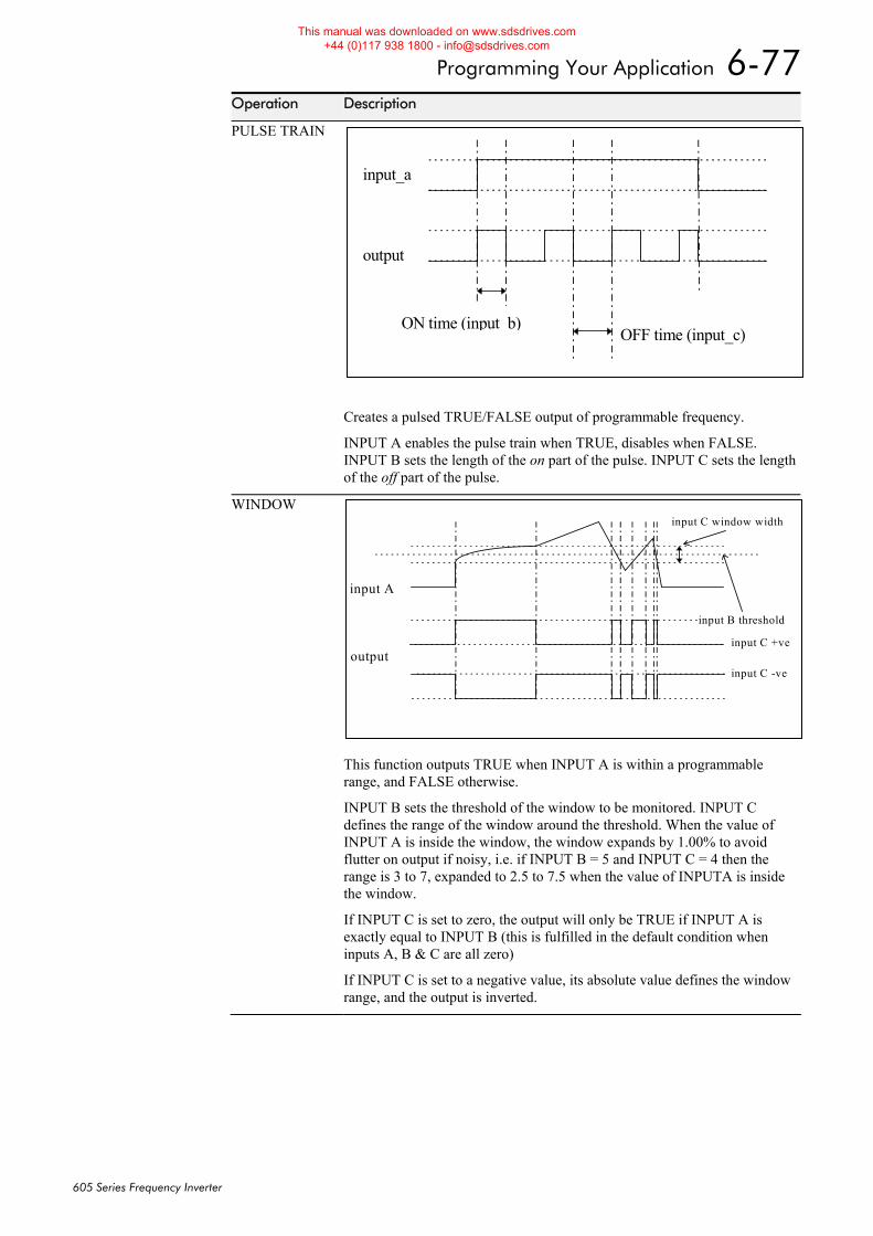
Programming Your Application 6-77
605 Series Frequency Inverter
Operation Description
PULSE TRAIN
Creates a pulsed TRUE/FALSE output of programmable frequency.
INPUT A enables the pulse train when TRUE, disables when FALSE. INPUT B sets the length of the on part of the pulse. INPUT C sets the length of the off part of the pulse.
WINDOW
This function outputs TRUE when INPUT A is within a programmable range, and FALSE otherwise.
INPUT B sets the threshold of the window to be monitored. INPUT C defines the range of the window around the threshold. When the value of INPUT A is inside the window, the window expands by 1.00% to avoid flutter on output if noisy, i.e. if INPUT B = 5 and INPUT C = 4 then the range is 3 to 7, expanded to 2.5 to 7.5 when the value of INPUTA is inside the window.
If INPUT C is set to zero, the output will only be TRUE if INPUT A is exactly equal to INPUT B (this is fulfilled in the default condition when inputs A, B & C are all zero)
If INPUT C is set to a negative value, its absolute value defines the window range, and the output is inverted.
input_a
output
ON time (input b)OFF time (input_c)
input A
output
input B threshold
input C window width
input C +ve
input C -ve
This manual was downloaded on www.sdsdrives.com +44 (0)117 938 1800 - [email protected]
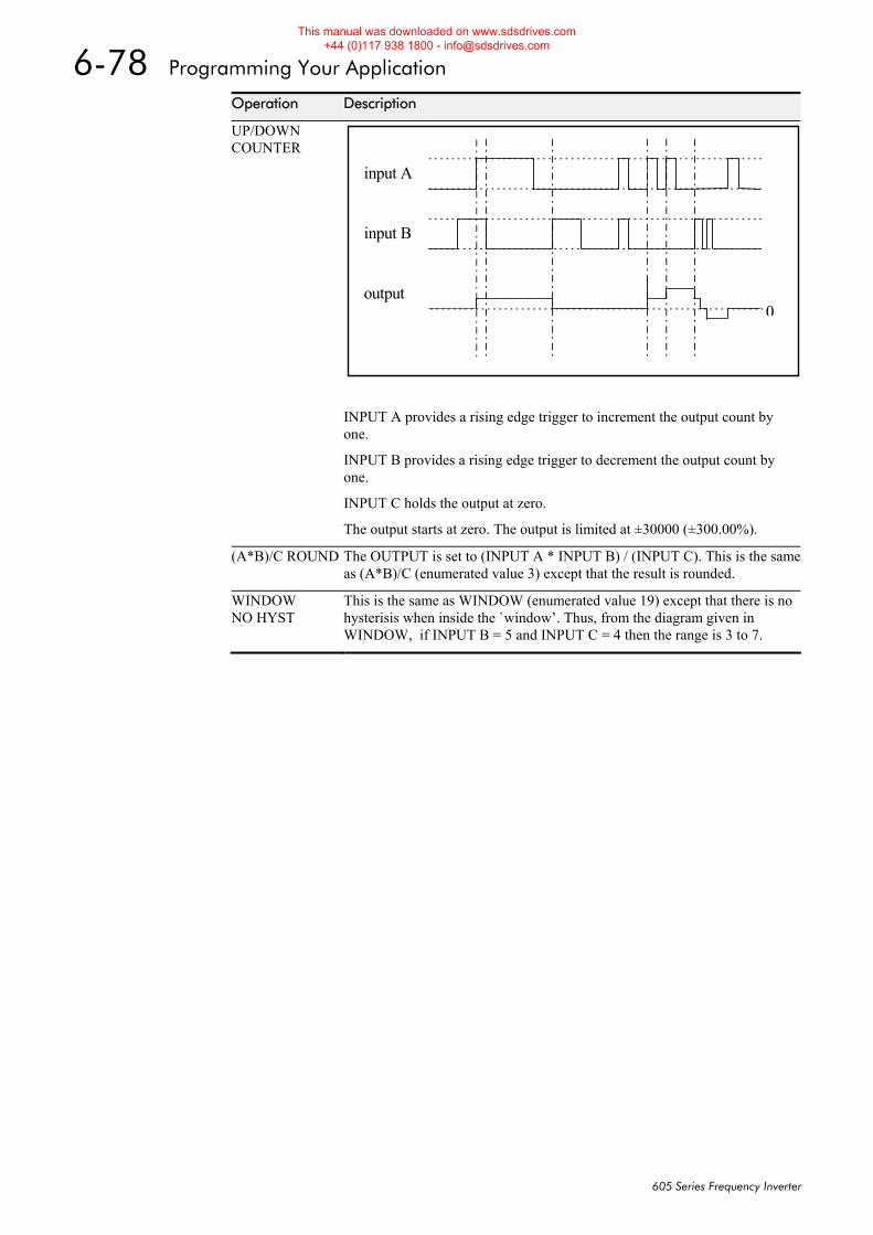
6-78 Programming Your Application
605 Series Frequency Inverter
Operation Description
UP/DOWN COUNTER
input A
input B
output0
INPUT A provides a rising edge trigger to increment the output count by one.
INPUT B provides a rising edge trigger to decrement the output count by one.
INPUT C holds the output at zero.
The output starts at zero. The output is limited at ±30000 (±300.00%).
(A*B)/C ROUND The OUTPUT is set to (INPUT A * INPUT B) / (INPUT C). This is the same as (A*B)/C (enumerated value 3) except that the result is rounded.
WINDOW NO HYST
This is the same as WINDOW (enumerated value 19) except that there is no hysterisis when inside the `window’. Thus, from the diagram given in WINDOW, if INPUT B = 5 and INPUT C = 4 then the range is 3 to 7.
This manual was downloaded on www.sdsdrives.com +44 (0)117 938 1800 - [email protected]
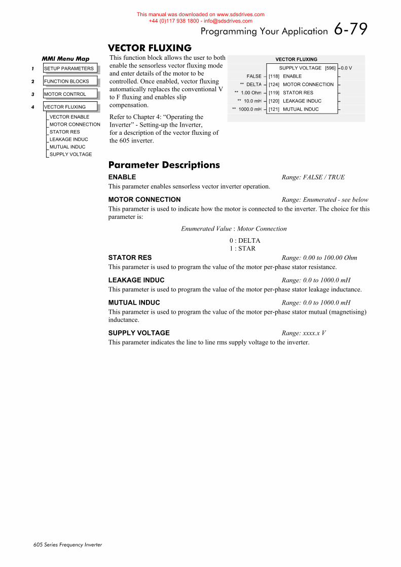
Programming Your Application 6-79
605 Series Frequency Inverter
VECTOR FLUXING This function block allows the user to both enable the sensorless vector fluxing mode and enter details of the motor to be controlled. Once enabled, vector fluxing automatically replaces the conventional V to F fluxing and enables slip compensation.
Refer to Chapter 4: “Operating the Inverter” - Setting-up the Inverter, for a description of the vector fluxing of the 605 inverter.
MMI Menu Map
1 SETUP PARAMETERS
2 FUNCTION BLOCKS
3 MOTOR CONTROL
4 VECTOR FLUXING
VECTOR ENABLE
MOTOR CONNECTION
STATOR RES
LEAKAGE INDUC
MUTUAL INDUC
SUPPLY VOLTAGE
VECTOR FLUXING
SUPPLY VOLTAGE [596] –0.0 V
FALSE – [118] ENABLE –
** DELTA – [124] MOTOR CONNECTION –
** 1.00 Ohm – [119] STATOR RES –
** 10.0 mH – [120] LEAKAGE INDUC –
** 1000.0 mH – [121] MUTUAL INDUC –
Parameter Descriptions ENABLE Range: FALSE / TRUE This parameter enables sensorless vector inverter operation.
MOTOR CONNECTION Range: Enumerated - see belowThis parameter is used to indicate how the motor is connected to the inverter. The choice for this parameter is:
Enumerated Value : Motor Connection
0 : DELTA 1 : STAR
STATOR RES Range: 0.00 to 100.00 Ohm This parameter is used to program the value of the motor per-phase stator resistance.
LEAKAGE INDUC Range: 0.0 to 1000.0 mH This parameter is used to program the value of the motor per-phase stator leakage inductance.
MUTUAL INDUC Range: 0.0 to 1000.0 mH This parameter is used to program the value of the motor per-phase stator mutual (magnetising) inductance.
SUPPLY VOLTAGE Range: xxxx.x V This parameter indicates the line to line rms supply voltage to the inverter.
This manual was downloaded on www.sdsdrives.com +44 (0)117 938 1800 - [email protected]
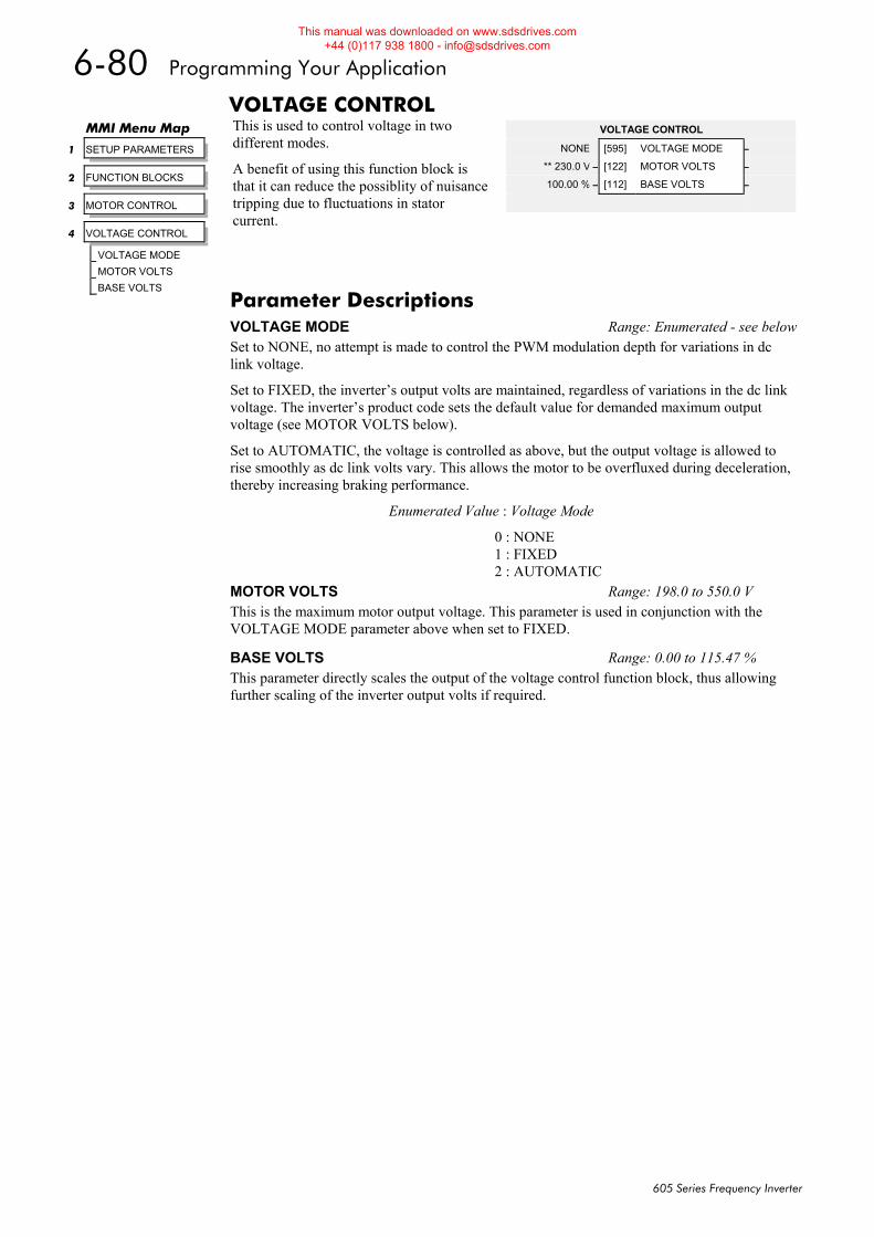
6-80 Programming Your Application
605 Series Frequency Inverter
VOLTAGE CONTROL This is used to control voltage in two different modes.
A benefit of using this function block is that it can reduce the possiblity of nuisance tripping due to fluctuations in stator current.
MMI Menu Map
1 SETUP PARAMETERS
2 FUNCTION BLOCKS
3 MOTOR CONTROL
4 VOLTAGE CONTROL
VOLTAGE MODE
MOTOR VOLTS
BASE VOLTS
VOLTAGE CONTROL
NONE [595] VOLTAGE MODE –
** 230.0 V – [122] MOTOR VOLTS –
100.00 % – [112] BASE VOLTS –
Parameter Descriptions VOLTAGE MODE Range: Enumerated - see belowSet to NONE, no attempt is made to control the PWM modulation depth for variations in dc link voltage.
Set to FIXED, the inverter’s output volts are maintained, regardless of variations in the dc link voltage. The inverter’s product code sets the default value for demanded maximum output voltage (see MOTOR VOLTS below).
Set to AUTOMATIC, the voltage is controlled as above, but the output voltage is allowed to rise smoothly as dc link volts vary. This allows the motor to be overfluxed during deceleration, thereby increasing braking performance.
Enumerated Value : Voltage Mode
0 : NONE 1 : FIXED 2 : AUTOMATIC
MOTOR VOLTS Range: 198.0 to 550.0 V This is the maximum motor output voltage. This parameter is used in conjunction with the VOLTAGE MODE parameter above when set to FIXED.
BASE VOLTS Range: 0.00 to 115.47 % This parameter directly scales the output of the voltage control function block, thus allowing further scaling of the inverter output volts if required.
This manual was downloaded on www.sdsdrives.com +44 (0)117 938 1800 - [email protected]
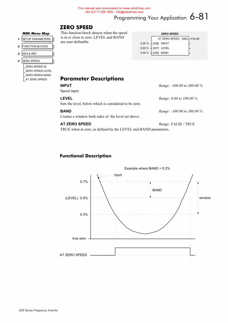
Programming Your Application 6-81
605 Series Frequency Inverter
ZERO SPEED This function block detects when the speed is at or close to zero. LEVEL and BAND are user-definable.
Functional Description
true zero
(LEVEL)
input
AT ZERO SPEED
0.5%
0.3%
0.7%
BAND
window
Example where BAND = 0.2%
MMI Menu Map
1 SETUP PARAMETERS
2 FUNCTION BLOCKS
3 SEQ & REF
4 ZERO SPEED
ZERO SPEED IN
ZERO SPEED LEVEL
ZERO SPEED BAND
AT ZERO SPEED
ZERO SPEED
AT ZERO SPEED [360] – FALSE
0.00 % – [358] INPUT –
0.50 % – [357] LEVEL –
0.00 % – [359] BAND –
Parameter Descriptions INPUT Range: -300.00 to 300.00 % Speed input.
LEVEL Range: 0.00 to 100.00 % Sets the level, below which is considered to be zero.
BAND Range: -300.00 to 300.00 % Creates a window both sides of the level set above.
AT ZERO SPEED Range: FALSE / TRUE TRUE when at zero, as defined by the LEVEL and BAND parameters.
This manual was downloaded on www.sdsdrives.com +44 (0)117 938 1800 - [email protected]

6-82 Programming Your Application
605 Series Frequency Inverter
Motor-Specific Parameters When copying an application from the Operator Station to another 605 Inverter, the following motor-specific parameters need not be written to - refer to Chapter 5: “The Operator Station” - Copying an Application.
Tag
FLY SEARCH BOOST 32
FULL LOAD CALIB 64
NO LOAD CALIB 65
NAMEPLATE RPM 83
MOTOR POLES 84
SLIP MOTOR LIMIT 85
SLIP REGEN LIMIT 86
DEFLUX DELAY 100
BASE FREQUENCY 106
FIXED BOOST 107
AUTO BOOST 108
STATOR RES 119
LEAKAGE INDUC 120
MUTUAL INDUC 121
MOTOR VOLTS 122
VECTOR FILTER TC 123
MOTOR CONNECTION 124
POWER FACTOR 242
ENCODER LINES 566
FLY SEARCH VOLTS 573
FLY SEARCH TIME 574
INJ FREQUENCY 577
INJ DC PULSE 579
INJ FINAL DC 580
INJ DC LEVEL 581
DEFLUX TIME 710
INJ BASE VOLTS 739
This manual was downloaded on www.sdsdrives.com +44 (0)117 938 1800 - [email protected]
Trips and Fault Finding 7-1
605 Series Frequency Inverter
7TRIPS AND FAULT FINDING Trips
What Happens when a Trip Occurs When a trip occurs, the Inverter’s power stage is immediately disabled causing the motor and load to coast to a stop. The trip is latched until action is taken to reset it. This ensures that trips due to transient conditions are captured and the Inverter is disabled, even when the original cause of the trip is no longer present
Inverter Indications If a trip condition is detected the unit displays and performs the following actions.
1. The HEALTH LED flashes indicating a Trip condition has occurred. (Investigate, find and remove the cause of the trip.)
1. The programming block SEQUENCING LOGIC::TRIPPED signal is set to TRUE. The DIGITAL OUTPUT 1 (HEALTH) digital output changes between TRUE/FALSE, depending on the output logic.
Operator Station Indications (when connected) If a trip condition is detected the MMI displays and performs the following actions.
1. The HEALTH LED on the Operator Station flashes indicating a Trip condition has occurred and a trip message is displayed stating the cause of the trip.
2. The programming block SEQUENCING LOGIC::TRIPPED signal is set to TRUE. The DIGITAL OUTPUT 1 (HEALTH) digital output changes between TRUE/FALSE, depending on the output logic.
3. The trip message(s) must be acknowledged by pressing the E key. Refer to Chapter 5: “The Operator Station” - Message Displays.
Resetting a Trip Condition All trips must be reset before the Inverter can be re-enabled. A trip can only be reset once the trip condition is no longer active, i.e. a trip due to a heatsink over-temperature will not reset until the temperature is below the trip level.
Note: More than one trip can be active at any time. For example, it is possible for both the HEATSINK TEMP and the LINK OVERVOLTS trips to be active. Alternatively it is possible for the Inverter to trip due to an OVERCURRENT error and then for the HEATSINK TEMP trip to become active after the Inverter has stopped (this may occur due to the thermal time constant of the heatsink).
Reset the trip(s) using the remote trip reset input, or by pressing the STOP/RESET key on the Operator Station.
Success is indicated by the HEALTH LED (on the unit or MMI) ceasing to flash and returning to a healthy “ON” state. The programming block SEQUENCING LOGIC::TRIPPED output is reset to FALSE.
DEFAULT
DEFAULT
This manual was downloaded on www.sdsdrives.com +44 (0)117 938 1800 - [email protected]
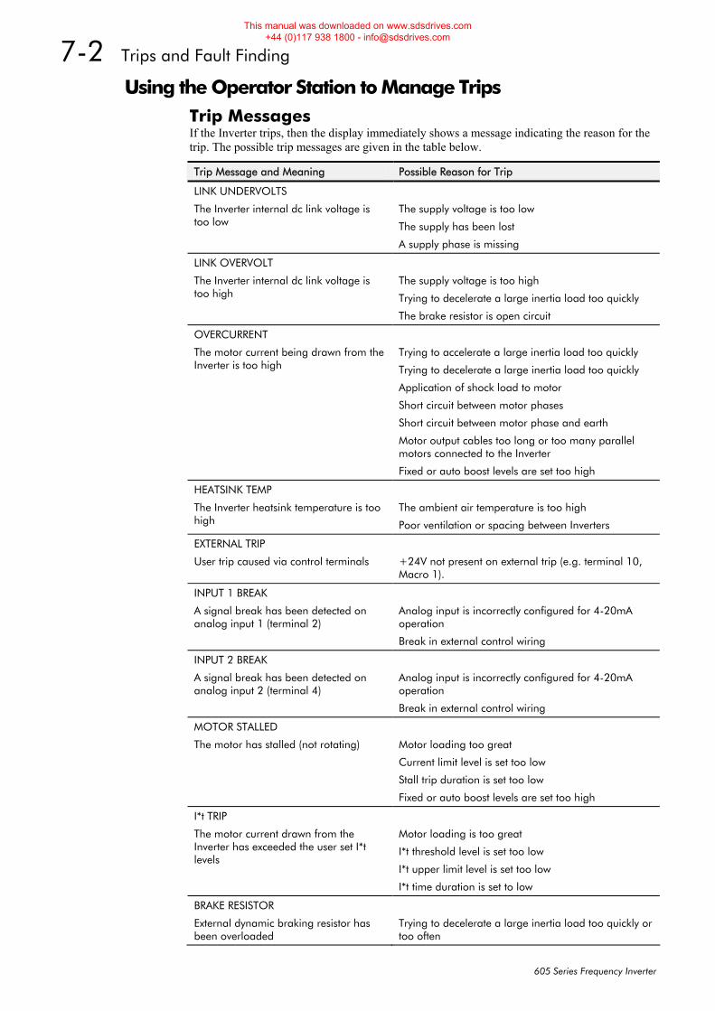
7-2 Trips and Fault Finding
605 Series Frequency Inverter
Using the Operator Station to Manage Trips Trip Messages If the Inverter trips, then the display immediately shows a message indicating the reason for the trip. The possible trip messages are given in the table below.
Trip Message and Meaning Possible Reason for Trip
LINK UNDERVOLTS
The Inverter internal dc link voltage is too low
The supply voltage is too low
The supply has been lost
A supply phase is missing
LINK OVERVOLT
The Inverter internal dc link voltage is too high
The supply voltage is too high
Trying to decelerate a large inertia load too quickly
The brake resistor is open circuit
OVERCURRENT
The motor current being drawn from the Inverter is too high
Trying to accelerate a large inertia load too quickly
Trying to decelerate a large inertia load too quickly
Application of shock load to motor
Short circuit between motor phases
Short circuit between motor phase and earth
Motor output cables too long or too many parallel motors connected to the Inverter
Fixed or auto boost levels are set too high
HEATSINK TEMP
The Inverter heatsink temperature is too high
The ambient air temperature is too high
Poor ventilation or spacing between Inverters
EXTERNAL TRIP
User trip caused via control terminals
+24V not present on external trip (e.g. terminal 10, Macro 1).
INPUT 1 BREAK
A signal break has been detected on analog input 1 (terminal 2)
Analog input is incorrectly configured for 4-20mA operation
Break in external control wiring
INPUT 2 BREAK
A signal break has been detected on analog input 2 (terminal 4)
Analog input is incorrectly configured for 4-20mA operation
Break in external control wiring
MOTOR STALLED
The motor has stalled (not rotating)
Motor loading too great
Current limit level is set too low
Stall trip duration is set too low
Fixed or auto boost levels are set too high
I*t TRIP
The motor current drawn from the Inverter has exceeded the user set I*t levels
Motor loading is too great
I*t threshold level is set too low
I*t upper limit level is set too low
I*t time duration is set to low
BRAKE RESISTOR
External dynamic braking resistor has been overloaded
Trying to decelerate a large inertia load too quickly or too often
This manual was downloaded on www.sdsdrives.com +44 (0)117 938 1800 - [email protected]
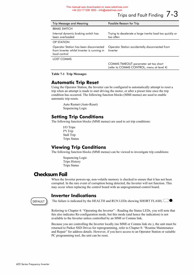
Trips and Fault Finding 7-3
605 Series Frequency Inverter
Trip Message and Meaning Possible Reason for Trip
BRAKE SWITCH
Internal dynamic braking switch has been overloaded
Trying to decelerate a large inertia load too quickly or too often
OP STATION
Operator Station has been disconnected from Inverter whilst Inverter is running in local control
Operator Station accidentally disconnected from Inverter
LOST COMMS
COMMS TIMEOUT parameter set too short (refer to COMMS CONTROL, menu at level 4)
Table 7-1 Trip Messages
Automatic Trip Reset Using the Operator Station, the Inverter can be configured to automatically attempt to reset a trip when an attempt is made to start driving the motor, or after a preset time once the trip condition has occurred. The following function blocks (MMI menus) are used to enable automatic trip resets.
Auto Restart (Auto-Reset) Sequencing Logic
Setting Trip Conditions The following function blocks (MMI menus) are used to set trip conditions:
I/O Trips I*t Trip Stall Trip Trips Status
Viewing Trip Conditions The following function blocks (MMI menus) can be viewed to investigate trip conditions:
Sequencing Logic Trips History Trips Status
Checksum Fail When the Inverter powers-up, non-volatile memory is checked to ensure that it has not been corrupted. In the rare event of corruption being detected, the Inverter will not function. This may occur when replacing the control board with an unprogrammed control board.
Inverter Indications The failure is indicated by the HEALTH and RUN LEDs showing SHORT FLASH, .
Referring to Chapter 4: “Operating the Inverter” - Reading the Status LEDs, you will note that this also indicates Re-configuration mode, but this mode (and hence the indication) is not available to the Inverter unless controlled by an MMI or Comms link.
Because you are controlling the Inverter locally (no MMI or Comms link etc.), the unit must be returned to Parker SSD Drives for reprogramming, refer to Chapter 8: “Routine Maintenance and Repair” for address details. However, if you have access to an Operator Station or suitable PC programming tool, the unit can be reset.
DEFAULT
This manual was downloaded on www.sdsdrives.com +44 (0)117 938 1800 - [email protected]
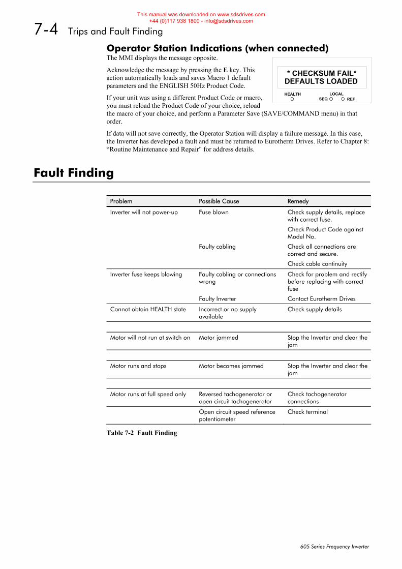
7-4 Trips and Fault Finding
605 Series Frequency Inverter
Operator Station Indications (when connected) The MMI displays the message opposite.
Acknowledge the message by pressing the E key. This action automatically loads and saves Macro 1 default parameters and the ENGLISH 50Hz Product Code.
If your unit was using a different Product Code or macro, you must reload the Product Code of your choice, reload the macro of your choice, and perform a Parameter Save (SAVE/COMMAND menu) in that order.
If data will not save correctly, the Operator Station will display a failure message. In this case, the Inverter has developed a fault and must be returned to Eurotherm Drives. Refer to Chapter 8: “Routine Maintenance and Repair" for address details.
Fault Finding
Problem Possible Cause Remedy
Inverter will not power-up Fuse blown Check supply details, replace with correct fuse.
Check Product Code against Model No.
Faulty cabling Check all connections are correct and secure.
Check cable continuity
Inverter fuse keeps blowing Faulty cabling or connections wrong
Check for problem and rectify before replacing with correct fuse
Faulty Inverter Contact Eurotherm Drives
Cannot obtain HEALTH state Incorrect or no supply available
Check supply details
Motor will not run at switch on Motor jammed Stop the Inverter and clear the jam
Motor runs and stops Motor becomes jammed Stop the Inverter and clear the jam
Motor runs at full speed only Reversed tachogenerator or open circuit tachogenerator
Check tachogenerator connections
Open circuit speed reference potentiometer
Check terminal
Table 7-2 Fault Finding
HEALTH LOCALSEQ REF
11DEFAULTS LOADED
* CHECKSUM FAIL*
This manual was downloaded on www.sdsdrives.com +44 (0)117 938 1800 - [email protected]
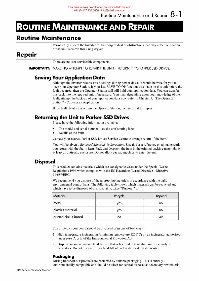
Routine Maintenance and Repair 8-1
605 Series Frequency Inverter
8ROUTINE MAINTENANCE AND REPAIR Routine Maintenance
Periodically inspect the Inverter for build-up of dust or obstructions that may affect ventilation of the unit. Remove this using dry air.
Repair There are no user-serviceable components.
IMPORTANT: MAKE NO ATTEMPT TO REPAIR THE UNIT - RETURN IT TO PARKER SSD DRIVES.
Saving Your Application Data Although the Inverter retains saved settings during power-down, it would be wise for you to keep your Operator Station. If your last SAVE TO OP function was made on this unit before the fault occurred, then the Operator Station will still hold your application data. You can transfer this back into the repaired unit, if necessary. You may, depending upon your knowledge of the fault, attempt the back-up of your application data now, refer to Chapter 5: “The Operator Station” - Copying an Application.
If the fault clearly lies within the Operator Station, then return it for repair.
Returning the Unit to Parker SSD Drives Please have the following information available:
• The model and serial number - see the unit’s rating label • Details of the fault
Contact your nearest Parker SSD Drives Service Centre to arrange return of the item.
You will be given a Returned Material Authorisation. Use this as a reference on all paperwork you return with the faulty item. Pack and despatch the item in the original packing materials; or at least an antistatic enclosure. Do not allow packaging chips to enter the unit.
Disposal This product contains materials which are consignable waste under the Special Waste Regulations 1996 which complies with the EC Hazardous Waste Directive - Directive 91/689/EEC.
We recommend you dispose of the appropriate materials in accordance with the valid environmental control laws. The following table shows which materials can be recycled and which have to be disposed of in a special way.{xe "Disposal" \f �}
Material Recycle Disposal
metal yes no
plastics material yes no
printed circuit board no yes
The printed circuit board should be disposed of in one of two ways:
1. High temperature incineration (minimum temperature 1200°C) by an incinerator authorised under parts A or B of the Environmental Protection Act
2. Disposal in an engineered land fill site that is licensed to take aluminium electrolytic capacitors. Do not dispose of in a land fill site set aside for domestic waste.
Packaging During transport our products are protected by suitable packaging. This is entirely environmentally compatible and should be taken for central disposal as secondary raw material.
This manual was downloaded on www.sdsdrives.com +44 (0)117 938 1800 - [email protected]

8-2 Routine Maintenance and Repair
605 Series Frequency Inverter
This manual was downloaded on www.sdsdrives.com +44 (0)117 938 1800 - [email protected]
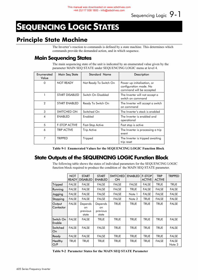
Sequencing Logic 9-1
605 Series Frequency Inverter
9SEQUENCING LOGIC STATES Principle State Machine
The Inverter’s reaction to commands is defined by a state machine. This determines which commands provide the demanded action, and in which sequence.
Main Sequencing States The main sequencing state of the unit is indicated by an enumerated value given by the parameter MAIN SEQ STATE under SEQUENCING LOGIC menu at level 4.
Enumerated Value
Main Seq State Standard Name Description
0 NOT READY Not Ready To Switch On Power up initialisation, or configuration mode. No command will be accepted
1 START DISABLED Switch On Disabled The Inverter will not accept a switch on command
2 START ENABLED Ready To Switch On The Inverter will accept a switch on command
3 SWITCHED ON Switched On The Inverter’s stack is enabled
4 ENABLED Enabled The Inverter is enabled and operational
5 F-STOP ACTIVE Fast-Stop Active Fast stop is active
6 TRIP ACTIVE Trip Active The Inverter is processing a trip event
7 TRIPPED Tripped The Inverter is tripped awaiting trip reset
Table 9-1 Enumerated Values for the SEQUENCING LOGIC Function Block
State Outputs of the SEQUENCING LOGIC Function Block The following table shows the states of individual parameters for the SEQUENCING LOGIC function block required to produce the condition of the MAIN SEQ STATE parameter.
NOT READY
START DISABLED
START ENABLED
SWITCHED ON
ENABLED F-STOP ACTIVE
TRIP ACTIVE
TRIPPED
Tripped FALSE FALSE FALSE FALSE FALSE FALSE TRUE TRUE
Running FALSE FALSE FALSE FALSE TRUE FALSE FALSE FALSE
Jogging FALSE FALSE FALSE FALSE Note 1 FALSE FALSE FALSE
Stopping FALSE FALSE FALSE FALSE Note 2 TRUE FALSE FALSE
Output Contactor
FALSE Depends on
previous state
Depends on
previous state
TRUE TRUE TRUE TRUE FALSE
Switch On Enable
FALSE FALSE TRUE TRUE TRUE TRUE TRUE FALSE
Switched On
FALSE FALSE FALSE TRUE TRUE TRUE TRUE FALSE
Ready FALSE FALSE FALSE TRUE TRUE TRUE TRUE FALSE
Healthy O/P
TRUE TRUE TRUE TRUE TRUE TRUE FALSE FALSE Note 3
Table 9-2 Parameter States for the MAIN SEQ STATE Parameter
This manual was downloaded on www.sdsdrives.com +44 (0)117 938 1800 - [email protected]
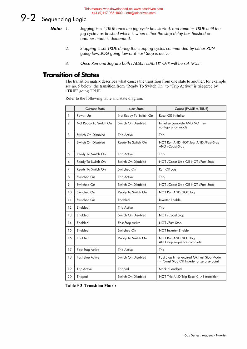
9-2 Sequencing Logic
605 Series Frequency Inverter
Note: 1. Jogging is set TRUE once the jog cycle has started, and remains TRUE until the jog cycle has finished which is when either the stop delay has finished or another mode is demanded. 2. Stopping is set TRUE during the stopping cycles commanded by either RUN going low, JOG going low or if Fast Stop is active. 3. Once Run and Jog are both FALSE, HEALTHY O/P will be set TRUE.
Transition of States The transition matrix describes what causes the transition from one state to another, for example see no. 5 below: the transition from “Ready To Switch On” to “Trip Active” is triggered by “TRIP” going TRUE.
Refer to the following table and state diagram.
Current State Next State Cause (FALSE to TRUE)
1 Power Up Not Ready To Switch On Reset OR initialise
2 Not Ready To Switch On Switch On Disabled Initialise complete AND NOT re-configuration mode
3 Switch On Disabled Trip Active Trip
4 Switch On Disabled Ready To Switch On NOT Run AND NOT Jog AND /Fast-Stop AND /Coast-Stop
5 Ready To Switch On Trip Active Trip
6 Ready To Switch On Switch On Disabled NOT /Coast-Stop OR NOT /Fast-Stop
7 Ready To Switch On Switched On Run OR Jog
8 Switched On Trip Active Trip
9 Switched On Switch On Disabled NOT /Coast-Stop OR NOT /Fast-Stop
10 Switched On Ready To Switch On NOT Run AND NOT Jog
11 Switched On Enabled Inverter Enable
12 Enabled Trip Active Trip
13 Enabled Switch On Disabled NOT /Coast Stop
14 Enabled Fast Stop Active NOT /Fast Stop
15 Enabled Switched On NOT Inverter Enable
16 Enabled Ready To Switch On NOT Run AND NOT Jog AND stop sequence complete
17 Fast Stop Active Trip Active Trip
18 Fast Stop Active Switch On Disabled Fast Stop timer expired OR Fast Stop Mode = Coast Stop OR Inverter at zero setpoint
19 Trip Active Tripped Stack quenched
20 Tripped Switch On Disabled NOT Trip AND Trip Reset 0->1 transition
Table 9-3 Transition Matrix
This manual was downloaded on www.sdsdrives.com +44 (0)117 938 1800 - [email protected]
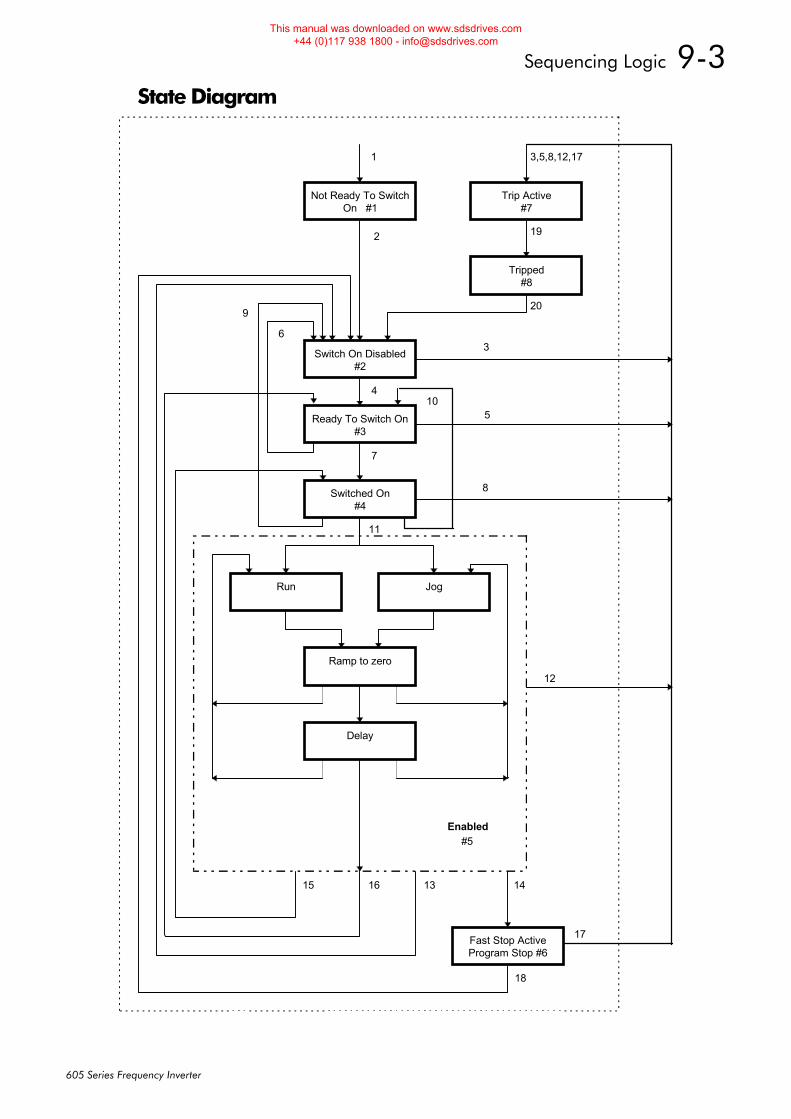
Sequencing Logic 9-3
605 Series Frequency Inverter
State Diagram
Not Ready To SwitchOn #1
Ready To Switch On#3
Switch On Disabled#2
Run Jog
Ramp to zero
Delay
Fast Stop ActiveProgram Stop #6
Enabled
Trip Active#7
1
2
11
15 14
7
20
4
16
3,5,8,12,17
Switched On#4
6
9
Tripped#8
19
13
18
#5
10
3
5
8
12
17
This manual was downloaded on www.sdsdrives.com +44 (0)117 938 1800 - [email protected]
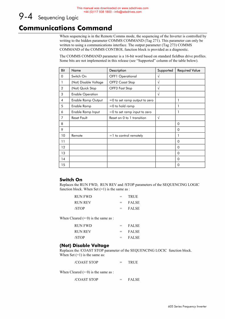
9-4 Sequencing Logic
605 Series Frequency Inverter
Communications Command When sequencing is in the Remote Comms mode, the sequencing of the Inverter is controlled by writing to the hidden parameter COMMS COMMAND (Tag 271). This parameter can only be written to using a communications interface. The output parameter (Tag 273) COMMS COMMAND of the COMMS CONTROL function block is provided as a diagnostic.
The COMMS COMMAND parameter is a 16-bit word based on standard fieldbus drive profiles. Some bits are not implemented in this release (see “Supported” column of the table below).
Bit Name Description Supported Required Value
0 Switch On OFF1 Operational √
1 (Not) Disable Voltage OFF2 Coast Stop √
2 (Not) Quick Stop OFF3 Fast Stop √
3 Enable Operation √
4 Enable Ramp Output =0 to set ramp output to zero 1
5 Enable Ramp =0 to hold ramp 1
6 Enable Ramp Input =0 to set ramp input to zero 1
7 Reset Fault Reset on 0 to 1 transition √
8 0
9 0
10 Remote =1 to control remotely 1
11 0
12 0
13 0
14 0
15 0
Switch On Replaces the RUN FWD, RUN REV and /STOP parameters of the SEQUENCING LOGIC function block. When Set (=1) is the same as :
RUN FWD = TRUE RUN REV = FALSE /STOP = FALSE
When Cleared (= 0) is the same as :
RUN FWD = FALSE RUN REV = FALSE /STOP = FALSE
(Not) Disable Voltage Replaces the /COAST STOP parameter of the SEQUENCING LOCIC function block. When Set (=1) is the same as:
/COAST STOP = TRUE
When Cleared (= 0) is the same as :
/COAST STOP = FALSE
This manual was downloaded on www.sdsdrives.com +44 (0)117 938 1800 - [email protected]
Sequencing Logic 9-5
605 Series Frequency Inverter
(Not) Quick Stop Replaces the /FAST STOP parameter on the SEQUENCING LOGIC function block. When Set (=1) is the same as:
/FAST STOP = TRUE
When Cleared (= 0) is the same as :
/FAST STOP = FALSE
Enable Operation Replaces the DRIVE ENABLE parameter on the SEQUENCING LOGIC function block. When Set (=1) is the same as:
DRIVE ENABLE = TRUE
When Cleared (= 0) is the same as :
DRIVE ENABLE = FALSE
Enable Ramp Output, Enable Ramp, Enable Ramp Input Not implemented. The state of these bits must be set (=1) to allow this feature to be added in the future.
Reset Fault Replaces the REM TRIP RESET parameter on the SEQUENCING LOCIC function block. When Set (=1) is the same as:
REM TRIP RESET = TRUE
When Cleared (= 0) is the same as :
REM TRIP RESET = FALSE
Remote Not implemented. It is intended to allow the PLC to toggle between local and remote. The state of this must be set (=1) to allow this feature to be added in the future.
Example Commands
047F hexadecimal to RUN
047E hexadecimal to STOP
This manual was downloaded on www.sdsdrives.com +44 (0)117 938 1800 - [email protected]
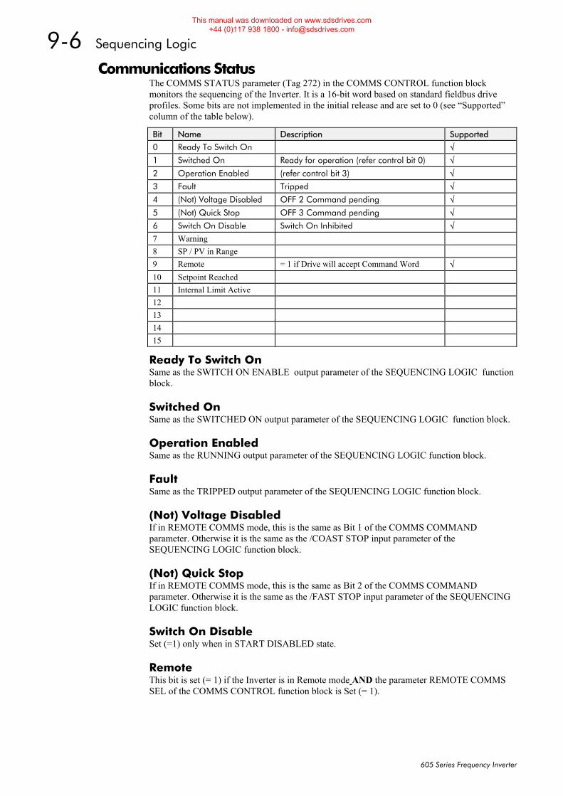
9-6 Sequencing Logic
605 Series Frequency Inverter
Communications Status The COMMS STATUS parameter (Tag 272) in the COMMS CONTROL function block monitors the sequencing of the Inverter. It is a 16-bit word based on standard fieldbus drive profiles. Some bits are not implemented in the initial release and are set to 0 (see “Supported” column of the table below).
Bit Name Description Supported
0 Ready To Switch On √ 1 Switched On Ready for operation (refer control bit 0) √ 2 Operation Enabled (refer control bit 3) √ 3 Fault Tripped √ 4 (Not) Voltage Disabled OFF 2 Command pending √ 5 (Not) Quick Stop OFF 3 Command pending √ 6 Switch On Disable Switch On Inhibited √ 7 Warning 8 SP / PV in Range 9 Remote = 1 if Drive will accept Command Word √ 10 Setpoint Reached 11 Internal Limit Active 12 13 14 15
Ready To Switch On Same as the SWITCH ON ENABLE output parameter of the SEQUENCING LOGIC function block.
Switched On Same as the SWITCHED ON output parameter of the SEQUENCING LOGIC function block.
Operation Enabled Same as the RUNNING output parameter of the SEQUENCING LOGIC function block.
Fault Same as the TRIPPED output parameter of the SEQUENCING LOGIC function block.
(Not) Voltage Disabled If in REMOTE COMMS mode, this is the same as Bit 1 of the COMMS COMMAND parameter. Otherwise it is the same as the /COAST STOP input parameter of the SEQUENCING LOGIC function block.
(Not) Quick Stop If in REMOTE COMMS mode, this is the same as Bit 2 of the COMMS COMMAND parameter. Otherwise it is the same as the /FAST STOP input parameter of the SEQUENCING LOGIC function block.
Switch On Disable Set (=1) only when in START DISABLED state.
Remote This bit is set (= 1) if the Inverter is in Remote mode AND the parameter REMOTE COMMS SEL of the COMMS CONTROL function block is Set (= 1).
This manual was downloaded on www.sdsdrives.com +44 (0)117 938 1800 - [email protected]
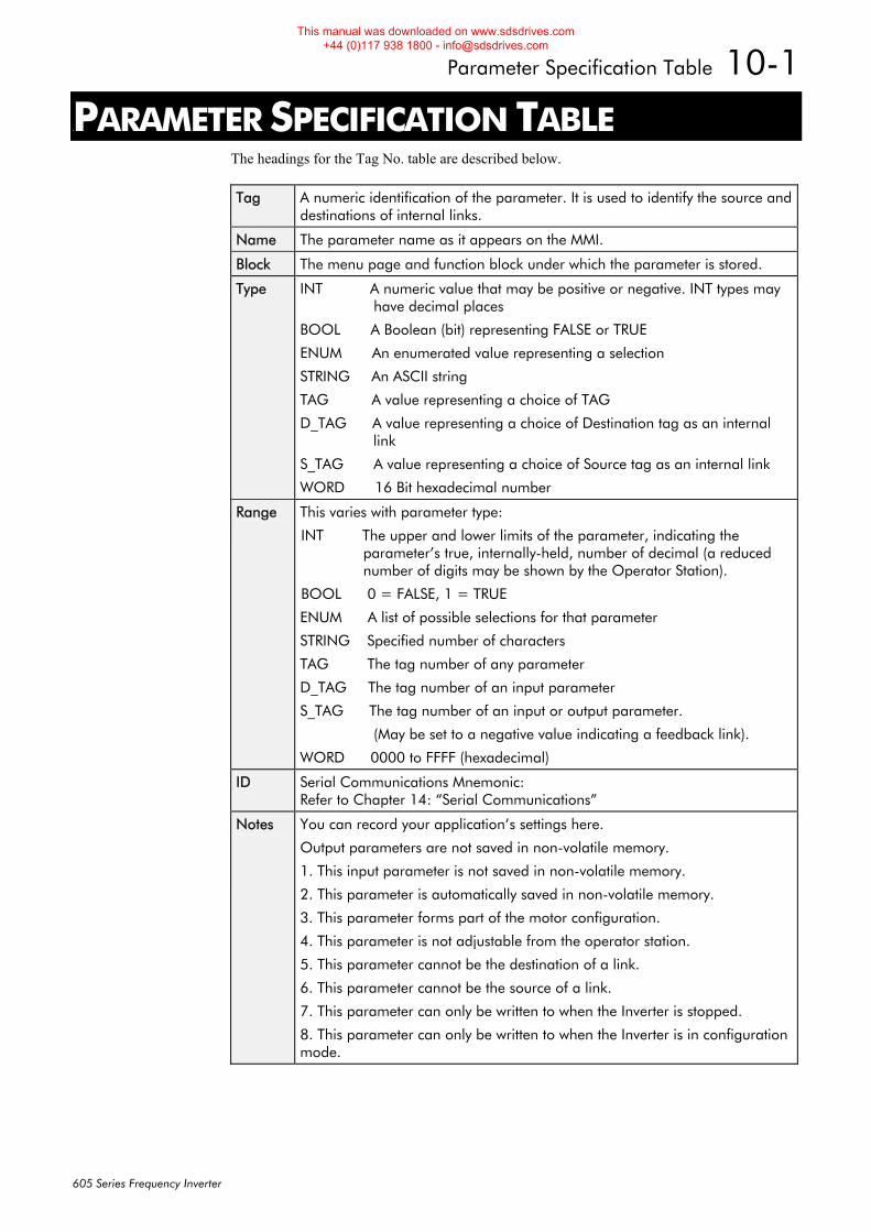
Parameter Specification Table 10-1
605 Series Frequency Inverter
10PARAMETER SPECIFICATION TABLE The headings for the Tag No. table are described below.
Tag A numeric identification of the parameter. It is used to identify the source and destinations of internal links.
Name The parameter name as it appears on the MMI.
Block The menu page and function block under which the parameter is stored.
Type INT A numeric value that may be positive or negative. INT types may have decimal places
BOOL A Boolean (bit) representing FALSE or TRUE
ENUM An enumerated value representing a selection
STRING An ASCII string
TAG A value representing a choice of TAG
D_TAG A value representing a choice of Destination tag as an internal link
S_TAG A value representing a choice of Source tag as an internal link
WORD 16 Bit hexadecimal number
Range
This varies with parameter type:
INT The upper and lower limits of the parameter, indicating the parameter’s true, internally-held, number of decimal (a reduced number of digits may be shown by the Operator Station).
BOOL 0 = FALSE, 1 = TRUE
ENUM A list of possible selections for that parameter
STRING Specified number of characters
TAG The tag number of any parameter
D_TAG The tag number of an input parameter
S_TAG The tag number of an input or output parameter.
(May be set to a negative value indicating a feedback link).
WORD 0000 to FFFF (hexadecimal)
ID Serial Communications Mnemonic: Refer to Chapter 14: “Serial Communications”
Notes
You can record your application’s settings here.
Output parameters are not saved in non-volatile memory.
1. This input parameter is not saved in non-volatile memory.
2. This parameter is automatically saved in non-volatile memory.
3. This parameter forms part of the motor configuration.
4. This parameter is not adjustable from the operator station.
5. This parameter cannot be the destination of a link.
6. This parameter cannot be the source of a link.
7. This parameter can only be written to when the Inverter is stopped.
8. This parameter can only be written to when the Inverter is in configuration mode.
This manual was downloaded on www.sdsdrives.com +44 (0)117 938 1800 - [email protected]
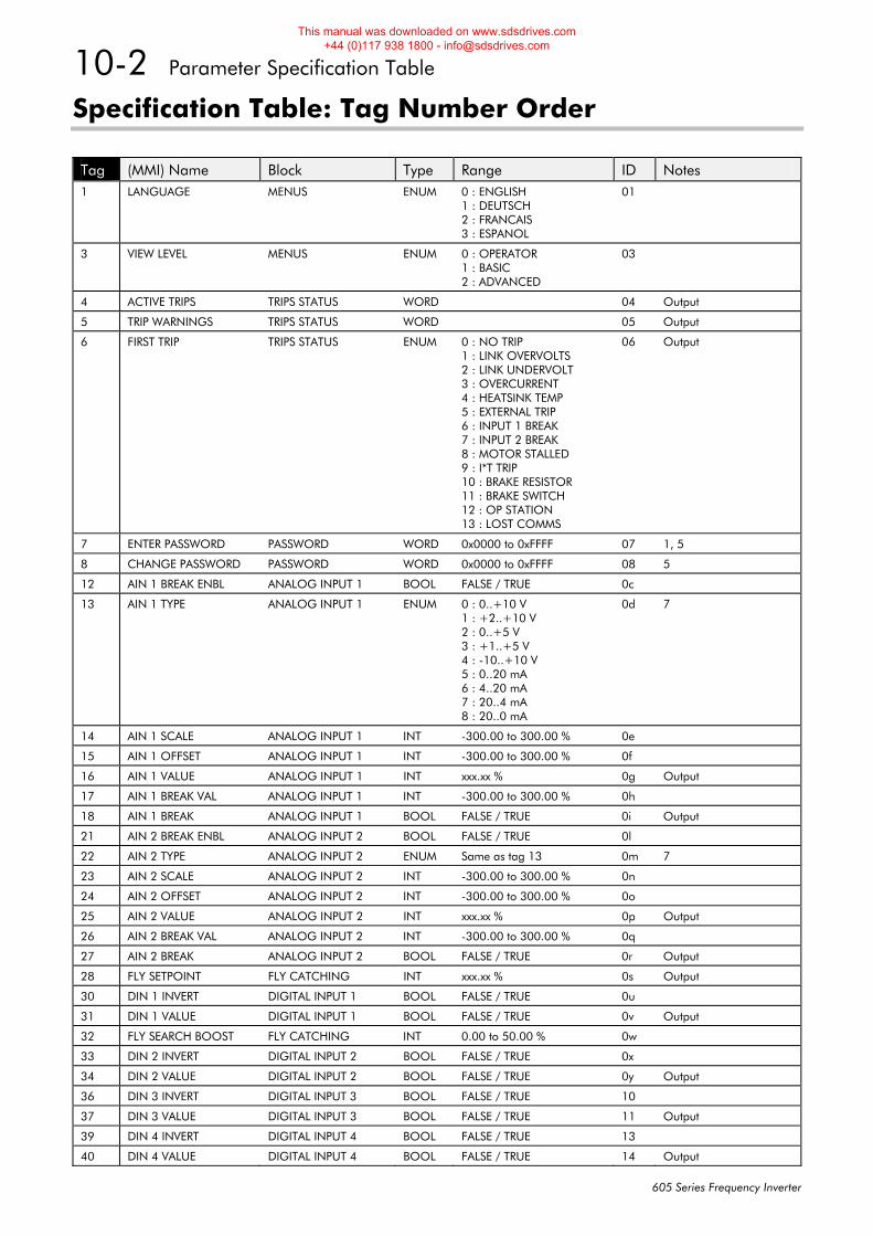
10-2 Parameter Specification Table
605 Series Frequency Inverter
Specification Table: Tag Number Order
Tag (MMI) Name Block Type Range ID Notes 1 LANGUAGE MENUS ENUM 0 : ENGLISH
1 : DEUTSCH 2 : FRANCAIS 3 : ESPANOL
01
3 VIEW LEVEL MENUS ENUM 0 : OPERATOR 1 : BASIC 2 : ADVANCED
03
4 ACTIVE TRIPS TRIPS STATUS WORD 04 Output
5 TRIP WARNINGS TRIPS STATUS WORD 05 Output
6 FIRST TRIP TRIPS STATUS ENUM 0 : NO TRIP 1 : LINK OVERVOLTS 2 : LINK UNDERVOLT 3 : OVERCURRENT 4 : HEATSINK TEMP 5 : EXTERNAL TRIP 6 : INPUT 1 BREAK 7 : INPUT 2 BREAK 8 : MOTOR STALLED 9 : I*T TRIP 10 : BRAKE RESISTOR 11 : BRAKE SWITCH 12 : OP STATION 13 : LOST COMMS
06 Output
7 ENTER PASSWORD PASSWORD WORD 0x0000 to 0xFFFF 07 1, 5
8 CHANGE PASSWORD PASSWORD WORD 0x0000 to 0xFFFF 08 5
12 AIN 1 BREAK ENBL ANALOG INPUT 1 BOOL FALSE / TRUE 0c
13 AIN 1 TYPE ANALOG INPUT 1 ENUM 0 : 0..+10 V 1 : +2..+10 V 2 : 0..+5 V 3 : +1..+5 V 4 : -10..+10 V 5 : 0..20 mA 6 : 4..20 mA 7 : 20..4 mA 8 : 20..0 mA
0d 7
14 AIN 1 SCALE ANALOG INPUT 1 INT -300.00 to 300.00 % 0e
15 AIN 1 OFFSET ANALOG INPUT 1 INT -300.00 to 300.00 % 0f
16 AIN 1 VALUE ANALOG INPUT 1 INT xxx.xx % 0g Output
17 AIN 1 BREAK VAL ANALOG INPUT 1 INT -300.00 to 300.00 % 0h
18 AIN 1 BREAK ANALOG INPUT 1 BOOL FALSE / TRUE 0i Output
21 AIN 2 BREAK ENBL ANALOG INPUT 2 BOOL FALSE / TRUE 0l
22 AIN 2 TYPE ANALOG INPUT 2 ENUM Same as tag 13 0m 7
23 AIN 2 SCALE ANALOG INPUT 2 INT -300.00 to 300.00 % 0n
24 AIN 2 OFFSET ANALOG INPUT 2 INT -300.00 to 300.00 % 0o
25 AIN 2 VALUE ANALOG INPUT 2 INT xxx.xx % 0p Output
26 AIN 2 BREAK VAL ANALOG INPUT 2 INT -300.00 to 300.00 % 0q
27 AIN 2 BREAK ANALOG INPUT 2 BOOL FALSE / TRUE 0r Output
28 FLY SETPOINT FLY CATCHING INT xxx.xx % 0s Output
30 DIN 1 INVERT DIGITAL INPUT 1 BOOL FALSE / TRUE 0u
31 DIN 1 VALUE DIGITAL INPUT 1 BOOL FALSE / TRUE 0v Output
32 FLY SEARCH BOOST FLY CATCHING INT 0.00 to 50.00 % 0w
33 DIN 2 INVERT DIGITAL INPUT 2 BOOL FALSE / TRUE 0x
34 DIN 2 VALUE DIGITAL INPUT 2 BOOL FALSE / TRUE 0y Output
36 DIN 3 INVERT DIGITAL INPUT 3 BOOL FALSE / TRUE 10
37 DIN 3 VALUE DIGITAL INPUT 3 BOOL FALSE / TRUE 11 Output
39 DIN 4 INVERT DIGITAL INPUT 4 BOOL FALSE / TRUE 13
40 DIN 4 VALUE DIGITAL INPUT 4 BOOL FALSE / TRUE 14 Output
This manual was downloaded on www.sdsdrives.com +44 (0)117 938 1800 - [email protected]
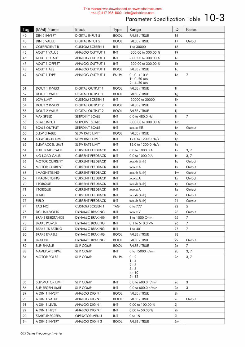
Parameter Specification Table 10-3
605 Series Frequency Inverter
Tag (MMI) Name Block Type Range ID Notes 42 DIN 5 INVERT DIGITAL INPUT 5 BOOL FALSE / TRUE 16
43 DIN 5 VALUE DIGITAL INPUT 5 BOOL FALSE / TRUE 17 Output
44 COEFFICIENT B CUSTOM SCREEN 1 INT 1 to 30000 18
45 AOUT 1 VALUE ANALOG OUTPUT 1 INT -300.00 to 300.00 % 19
46 AOUT 1 SCALE ANALOG OUTPUT 1 INT -300.00 to 300.00 % 1a
47 AOUT 1 OFFSET ANALOG OUTPUT 1 INT -300.00 to 300.00 % 1b
48 AOUT 1 ABS ANALOG OUTPUT 1 BOOL FALSE / TRUE 1c
49 AOUT 1 TYPE ANALOG OUTPUT 1 ENUM 0 : 0..+10 V 1 : 0..20 mA 2 : 4..20 mA
1d 7
51 DOUT 1 INVERT DIGITAL OUTPUT 1 BOOL FALSE / TRUE 1f
52 DOUT 1 VALUE DIGITAL OUTPUT 1 BOOL FALSE / TRUE 1g
53 LOW LIMIT CUSTOM SCREEN 1 INT -30000 to 30000 1h
54 DOUT 2 INVERT DIGITAL OUTPUT 2 BOOL FALSE / TRUE 1i
55 DOUT 2 VALUE DIGITAL OUTPUT 2 BOOL FALSE / TRUE 1j
57 MAX SPEED SETPOINT SCALE INT 0.0 to 480.0 Hz 1l 7
58 SCALE INPUT SETPOINT SCALE INT -300.00 to 300.00 % 1m
59 SCALE OUTPUT SETPOINT SCALE INT xxx.xx %lf 1n Output
60 SLEW ENABLE SLEW RATE LIMIT BOOL FALSE / TRUE 1o
61 SLEW DECEL LIMIT SLEW RATE LIMIT INT 12.0 to 1200.0 Hz/s 1p
62 SLEW ACCEL LIMIT SLEW RATE LIMIT INT 12.0 to 1200.0 Hz/s 1q
64 FULL LOAD CALIB CURRENT FEEDBACK INT 0.0 to 1000.0 A 1s 3, 7
65 NO LOAD CALIB CURRENT FEEDBACK INT 0.0 to 1000.0 A 1t 3, 7
66 MOTOR CURRENT CURRENT FEEDBACK INT xxx.xh % (h) 1u Output
67 MOTOR CURRENT CURRENT FEEDBACK INT xxxx.x A 1v Output
68 I MAGNETISING CURRENT FEEDBACK INT xxx.xh % (h) 1w Output
69 I MAGNETISING CURRENT FEEDBACK INT xxxx.x A 1x Output
70 I TORQUE CURRENT FEEDBACK INT xxx.xh % (h) 1y Output
71 I TORQUE CURRENT FEEDBACK INT xxxx.x A 1z Output
72 LOAD CURRENT FEEDBACK INT xxx.xh % (h) 20 Output
73 FIELD CURRENT FEEDBACK INT xxx.xh % (h) 21 Output
74 TAG NO CUSTOM SCREEN 1 TAG 0 to 777 22 5
75 DC LINK VOLTS DYNAMIC BRAKING INT xxxx.x V 23 Output
77 BRAKE RESISTANCE DYNAMIC BRAKING INT 1 to 1000 Ohm 25 7
78 BRAKE POWER DYNAMIC BRAKING INT 0.1 to 510.0 kW 26 7
79 BRAKE 1S RATING DYNAMIC BRAKING INT 1 to 40 27 7
80 BRAKE ENABLE DYNAMIC BRAKING BOOL FALSE / TRUE 28
81 BRAKING DYNAMIC BRAKING BOOL FALSE / TRUE 29 Output
82 SLIP ENABLE SLIP COMP BOOL FALSE / TRUE 2a 7
83 NAMEPLATE RPM SLIP COMP INT 0 to 15000 n/min 2b 3, 7
84 MOTOR POLES SLIP COMP ENUM 0 : 2 1 : 4 2 : 6 3 : 8 4 : 10 5 : 12
2c 3, 7
85 SLIP MOTOR LIMIT SLIP COMP INT 0.0 to 600.0 n/min 2d 3
86 SLIP REGEN LIMIT SLIP COMP INT 0.0 to 600.0 n/min 2e 3
89 A DIN 1 INVERT ANALOG DIGIN 1 BOOL FALSE / TRUE 2h
90 A DIN 1 VALUE ANALOG DIGIN 1 BOOL FALSE / TRUE 2i Output
91 A DIN 1 LEVEL ANALOG DIGIN 1 INT 0.00 to 100.00 % 2j
92 A DIN 1 HYST ANALOG DIGIN 1 INT 0.00 to 50.00 % 2k
93 STARTUP SCREEN OPERATOR MENU INT 0 to 15 2l
94 A DIN 2 INVERT ANALOG DIGIN 2 BOOL FALSE / TRUE 2m
This manual was downloaded on www.sdsdrives.com +44 (0)117 938 1800 - [email protected]
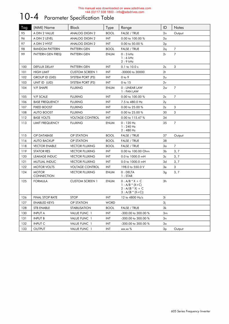
10-4 Parameter Specification Table
605 Series Frequency Inverter
Tag (MMI) Name Block Type Range ID Notes 95 A DIN 2 VALUE ANALOG DIGIN 2 BOOL FALSE / TRUE 2n Output
96 A DIN 2 LEVEL ANALOG DIGIN 2 INT 0.00 to 100.00 % 2o
97 A DIN 2 HYST ANALOG DIGIN 2 INT 0.00 to 50.00 % 2p
98 RANDOM PATTERN PATTERN GEN BOOL FALSE / TRUE 2q 7
99 PATTERN GEN FREQ PATTERN GEN ENUM 0 : 3 kHz 1 : 6 kHz 2 : 9 kHz
2r 7
100 DEFLUX DELAY PATTERN GEN INT 0.1 to 10.0 s 2s 3
101 HIGH LIMIT CUSTOM SCREEN 1 INT -30000 to 30000 2t
102 GROUP ID (GID) SYSTEM PORT (P3) INT 0 to 9 2u
103 UNIT ID (UID) SYSTEM PORT (P3) INT 0 to 15 2v
104 V/F SHAPE FLUXING ENUM 0 : LINEAR LAW 1 : FAN LAW
2w 7
105 V/F SCALE FLUXING INT 0.00 to 100.00 % 2x 7
106 BASE FREQUENCY FLUXING INT 7.5 to 480.0 Hz 2y
107 FIXED BOOST FLUXING INT 0.00 to 25.00 % 2z 3
108 AUTO BOOST FLUXING INT 0.00 to 25.00 % 30 3
112 BASE VOLTS VOLTAGE CONTROL INT 0.00 to 115.47 % 34
113 LIMIT FREQUENCY FLUXING ENUM 0 : 120 Hz 1 : 240 Hz 2 : 480 Hz
35 7
115 OP DATABASE OP STATION BOOL FALSE / TRUE 37 Output
116 AUTO BACKUP OP STATION BOOL FALSE / TRUE 38
118 VECTOR ENABLE VECTOR FLUXING BOOL FALSE / TRUE 3a 7
119 STATOR RES VECTOR FLUXING INT 0.00 to 100.00 Ohm 3b 3, 7
120 LEAKAGE INDUC VECTOR FLUXING INT 0.0 to 1000.0 mH 3c 3, 7
121 MUTUAL INDUC VECTOR FLUXING INT 0.0 to 1000.0 mH 3d 3, 7
122 MOTOR VOLTS VOLTAGE CONTROL INT 198.0 to 550.0 V 3e 3
124 MOTOR CONNECTION
VECTOR FLUXING ENUM 0 : DELTA 1 : STAR
3g 3, 7
125 FORMULA CUSTOM SCREEN 1 ENUM 0 : A/B * X + C 1 : A/B * (X+C) 2 : A/(B * X) + C 3 : A/(B * (X+C))
3h
126 FINAL STOP RATE STOP INT 12 to 4800 Hz/s 3i
127 ENABLED KEYS OP STATION WORD 3j
128 STB ENABLE STABILISATION BOOL FALSE / TRUE 3k
130 INPUT A VALUE FUNC 1 INT -300.00 to 300.00 % 3m
131 INPUT B VALUE FUNC 1 INT -300.00 to 300.00 % 3n
132 INPUT C VALUE FUNC 1 INT -300.00 to 300.00 % 3o
133 OUTPUT VALUE FUNC 1 INT xxx.xx % 3p Output
This manual was downloaded on www.sdsdrives.com +44 (0)117 938 1800 - [email protected]
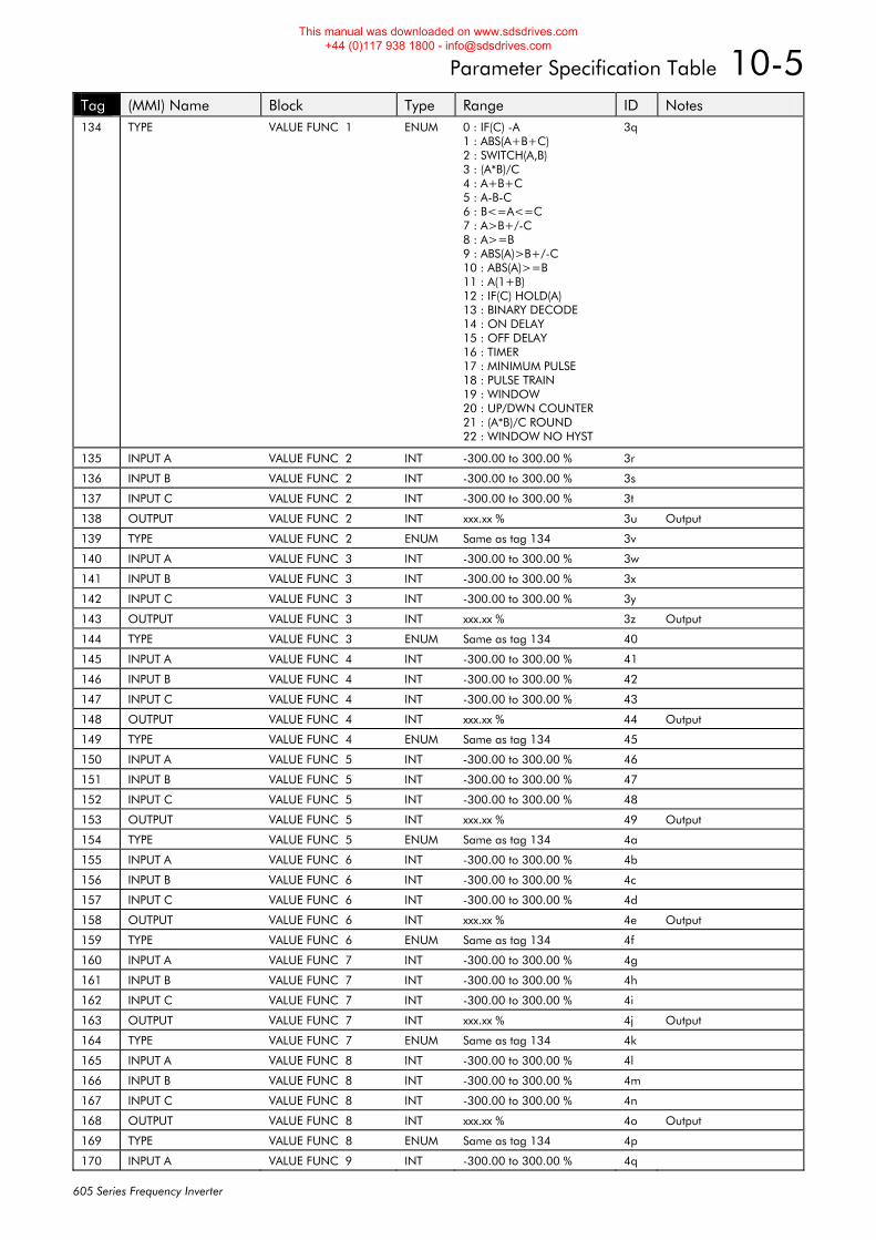
Parameter Specification Table 10-5
605 Series Frequency Inverter
Tag (MMI) Name Block Type Range ID Notes 134 TYPE VALUE FUNC 1 ENUM 0 : IF(C) -A
1 : ABS(A+B+C) 2 : SWITCH(A,B) 3 : (A*B)/C 4 : A+B+C 5 : A-B-C 6 : B<=A<=C 7 : A>B+/-C 8 : A>=B 9 : ABS(A)>B+/-C 10 : ABS(A)>=B 11 : A(1+B) 12 : IF(C) HOLD(A) 13 : BINARY DECODE 14 : ON DELAY 15 : OFF DELAY 16 : TIMER 17 : MINIMUM PULSE 18 : PULSE TRAIN 19 : WINDOW 20 : UP/DWN COUNTER 21 : (A*B)/C ROUND 22 : WINDOW NO HYST
3q
135 INPUT A VALUE FUNC 2 INT -300.00 to 300.00 % 3r
136 INPUT B VALUE FUNC 2 INT -300.00 to 300.00 % 3s
137 INPUT C VALUE FUNC 2 INT -300.00 to 300.00 % 3t
138 OUTPUT VALUE FUNC 2 INT xxx.xx % 3u Output
139 TYPE VALUE FUNC 2 ENUM Same as tag 134 3v
140 INPUT A VALUE FUNC 3 INT -300.00 to 300.00 % 3w
141 INPUT B VALUE FUNC 3 INT -300.00 to 300.00 % 3x
142 INPUT C VALUE FUNC 3 INT -300.00 to 300.00 % 3y
143 OUTPUT VALUE FUNC 3 INT xxx.xx % 3z Output
144 TYPE VALUE FUNC 3 ENUM Same as tag 134 40
145 INPUT A VALUE FUNC 4 INT -300.00 to 300.00 % 41
146 INPUT B VALUE FUNC 4 INT -300.00 to 300.00 % 42
147 INPUT C VALUE FUNC 4 INT -300.00 to 300.00 % 43
148 OUTPUT VALUE FUNC 4 INT xxx.xx % 44 Output
149 TYPE VALUE FUNC 4 ENUM Same as tag 134 45
150 INPUT A VALUE FUNC 5 INT -300.00 to 300.00 % 46
151 INPUT B VALUE FUNC 5 INT -300.00 to 300.00 % 47
152 INPUT C VALUE FUNC 5 INT -300.00 to 300.00 % 48
153 OUTPUT VALUE FUNC 5 INT xxx.xx % 49 Output
154 TYPE VALUE FUNC 5 ENUM Same as tag 134 4a
155 INPUT A VALUE FUNC 6 INT -300.00 to 300.00 % 4b
156 INPUT B VALUE FUNC 6 INT -300.00 to 300.00 % 4c
157 INPUT C VALUE FUNC 6 INT -300.00 to 300.00 % 4d
158 OUTPUT VALUE FUNC 6 INT xxx.xx % 4e Output
159 TYPE VALUE FUNC 6 ENUM Same as tag 134 4f
160 INPUT A VALUE FUNC 7 INT -300.00 to 300.00 % 4g
161 INPUT B VALUE FUNC 7 INT -300.00 to 300.00 % 4h
162 INPUT C VALUE FUNC 7 INT -300.00 to 300.00 % 4i
163 OUTPUT VALUE FUNC 7 INT xxx.xx % 4j Output
164 TYPE VALUE FUNC 7 ENUM Same as tag 134 4k
165 INPUT A VALUE FUNC 8 INT -300.00 to 300.00 % 4l
166 INPUT B VALUE FUNC 8 INT -300.00 to 300.00 % 4m
167 INPUT C VALUE FUNC 8 INT -300.00 to 300.00 % 4n
168 OUTPUT VALUE FUNC 8 INT xxx.xx % 4o Output
169 TYPE VALUE FUNC 8 ENUM Same as tag 134 4p
170 INPUT A VALUE FUNC 9 INT -300.00 to 300.00 % 4q
This manual was downloaded on www.sdsdrives.com +44 (0)117 938 1800 - [email protected]
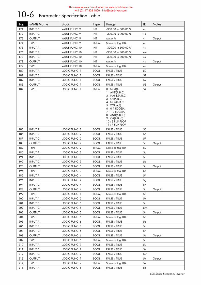
10-6 Parameter Specification Table
605 Series Frequency Inverter
Tag (MMI) Name Block Type Range ID Notes 171 INPUT B VALUE FUNC 9 INT -300.00 to 300.00 % 4r
172 INPUT C VALUE FUNC 9 INT -300.00 to 300.00 % 4s
173 OUTPUT VALUE FUNC 9 INT xxx.xx % 4t Output
174 TYPE VALUE FUNC 9 ENUM Same as tag 134 4u
175 INPUT A VALUE FUNC 10 INT -300.00 to 300.00 % 4v
176 INPUT B VALUE FUNC 10 INT -300.00 to 300.00 % 4w
177 INPUT C VALUE FUNC 10 INT -300.00 to 300.00 % 4x
178 OUTPUT VALUE FUNC 10 INT xxx.xx % 4y Output
179 TYPE VALUE FUNC 10 ENUM Same as tag 134 4z
180 INPUT A LOGIC FUNC 1 BOOL FALSE / TRUE 50
181 INPUT B LOGIC FUNC 1 BOOL FALSE / TRUE 51
182 INPUT C LOGIC FUNC 1 BOOL FALSE / TRUE 52
183 OUTPUT LOGIC FUNC 1 BOOL FALSE / TRUE 53 Output
184 TYPE LOGIC FUNC 1 ENUM 0 : NOT(A) 1 : AND(A,B,C) 2 : NAND(A,B,C) 3 : OR(A,B,C) 4 : NOR(A,B,C) 5 : XOR(A,B) 6 : 0-1 EDGE(A) 7 : 1-0 EDGE(A) 8 : AND(A,B,!C) 9 : OR(A,B,!C) 10 : S FLIP-FLOP 11 : R FLIP-FLOP
54
185 INPUT A LOGIC FUNC 2 BOOL FALSE / TRUE 55
186 INPUT B LOGIC FUNC 2 BOOL FALSE / TRUE 56
187 INPUT C LOGIC FUNC 2 BOOL FALSE / TRUE 57
188 OUTPUT LOGIC FUNC 2 BOOL FALSE / TRUE 58 Output
189 TYPE LOGIC FUNC 2 ENUM Same as tag 184 59
190 INPUT A LOGIC FUNC 3 BOOL FALSE / TRUE 5a
191 INPUT B LOGIC FUNC 3 BOOL FALSE / TRUE 5b
192 INPUT C LOGIC FUNC 3 BOOL FALSE / TRUE 5c
193 OUTPUT LOGIC FUNC 3 BOOL FALSE / TRUE 5d Output
194 TYPE LOGIC FUNC 3 ENUM Same as tag 184 5e
195 INPUT A LOGIC FUNC 4 BOOL FALSE / TRUE 5f
196 INPUT B LOGIC FUNC 4 BOOL FALSE / TRUE 5g
197 INPUT C LOGIC FUNC 4 BOOL FALSE / TRUE 5h
198 OUTPUT LOGIC FUNC 4 BOOL FALSE / TRUE 5i Output
199 TYPE LOGIC FUNC 4 ENUM Same as tag 184 5j
200 INPUT A LOGIC FUNC 5 BOOL FALSE / TRUE 5k
201 INPUT B LOGIC FUNC 5 BOOL FALSE / TRUE 5l
202 INPUT C LOGIC FUNC 5 BOOL FALSE / TRUE 5m
203 OUTPUT LOGIC FUNC 5 BOOL FALSE / TRUE 5n Output
204 TYPE LOGIC FUNC 5 ENUM Same as tag 184 5o
205 INPUT A LOGIC FUNC 6 BOOL FALSE / TRUE 5p
206 INPUT B LOGIC FUNC 6 BOOL FALSE / TRUE 5q
207 INPUT C LOGIC FUNC 6 BOOL FALSE / TRUE 5r
208 OUTPUT LOGIC FUNC 6 BOOL FALSE / TRUE 5s Output
209 TYPE LOGIC FUNC 6 ENUM Same as tag 184 5t
210 INPUT A LOGIC FUNC 7 BOOL FALSE / TRUE 5u
211 INPUT B LOGIC FUNC 7 BOOL FALSE / TRUE 5v
212 INPUT C LOGIC FUNC 7 BOOL FALSE / TRUE 5w
213 OUTPUT LOGIC FUNC 7 BOOL FALSE / TRUE 5x Output
214 TYPE LOGIC FUNC 7 ENUM Same as tag 184 5y
215 INPUT A LOGIC FUNC 8 BOOL FALSE / TRUE 5z
This manual was downloaded on www.sdsdrives.com +44 (0)117 938 1800 - [email protected]
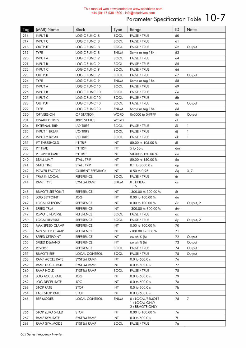
Parameter Specification Table 10-7
605 Series Frequency Inverter
Tag (MMI) Name Block Type Range ID Notes 216 INPUT B LOGIC FUNC 8 BOOL FALSE / TRUE 60
217 INPUT C LOGIC FUNC 8 BOOL FALSE / TRUE 61
218 OUTPUT LOGIC FUNC 8 BOOL FALSE / TRUE 62 Output
219 TYPE LOGIC FUNC 8 ENUM Same as tag 184 63
220 INPUT A LOGIC FUNC 9 BOOL FALSE / TRUE 64
221 INPUT B LOGIC FUNC 9 BOOL FALSE / TRUE 65
222 INPUT C LOGIC FUNC 9 BOOL FALSE / TRUE 66
223 OUTPUT LOGIC FUNC 9 BOOL FALSE / TRUE 67 Output
224 TYPE LOGIC FUNC 9 ENUM Same as tag 184 68
225 INPUT A LOGIC FUNC 10 BOOL FALSE / TRUE 69
226 INPUT B LOGIC FUNC 10 BOOL FALSE / TRUE 6a
227 INPUT C LOGIC FUNC 10 BOOL FALSE / TRUE 6b
228 OUTPUT LOGIC FUNC 10 BOOL FALSE / TRUE 6c Output
229 TYPE LOGIC FUNC 10 ENUM Same as tag 184 6d
230 OP VERSION OP STATION WORD 0x0000 to 0xFFFF 6e Output
231 DISABLED TRIPS TRIPS STATUS WORD 6f
234 EXTERNAL TRIP I/O TRIPS BOOL FALSE / TRUE 6i 1
235 INPUT 1 BREAK I/O TRIPS BOOL FALSE / TRUE 6j 1
236 INPUT 2 BREAK I/O TRIPS BOOL FALSE / TRUE 6k 1
237 I*T THRESHOLD I*T TRIP INT 50.00 to 105.00 % 6l
238 I*T TIME I*T TRIP INT 5 to 60 s 6m
239 I*T UPPER LIMIT I*T TRIP INT 50.00 to 150.00 % 6n
240 STALL LIMIT STALL TRIP INT 50.00 to 150.00 % 6o
241 STALL TIME STALL TRIP INT 0.1 to 3000.0 s 6p
242 POWER FACTOR CURRENT FEEDBACK INT 0.50 to 0.95 6q 3, 7
243 TRIM IN LOCAL REFERENCE BOOL FALSE / TRUE 6r
244 RAMP TYPE SYSTEM RAMP ENUM 0 : LINEAR 1 : S
6s
245 REMOTE SETPOINT REFERENCE INT -300.00 to 300.00 % 6t
246 JOG SETPOINT JOG INT 0.00 to 100.00 % 6u
247 LOCAL SETPOINT REFERENCE INT 0.00 to 100.00 % 6v Output, 2
248 SPEED TRIM REFERENCE INT -300.00 to 300.00 % 6w
249 REMOTE REVERSE REFERENCE BOOL FALSE / TRUE 6x
250 LOCAL REVERSE REFERENCE BOOL FALSE / TRUE 6y Output, 2
252 MAX SPEED CLAMP REFERENCE INT 0.00 to 100.00 % 70
253 MIN SPEED CLAMP REFERENCE INT -100.00 to 0.00 % 71
254 SPEED SETPOINT REFERENCE INT xxx.xh % (h) 72 Output
255 SPEED DEMAND REFERENCE INT xxx.xh % (h) 73 Output
256 REVERSE REFERENCE BOOL FALSE / TRUE 74 Output
257 REMOTE REF LOCAL CONTROL BOOL FALSE / TRUE 75 Output
258 RAMP ACCEL RATE SYSTEM RAMP INT 0.0 to 600.0 s 76
259 RAMP DECEL RATE SYSTEM RAMP INT 0.0 to 600.0 s 77
260 RAMP HOLD SYSTEM RAMP BOOL FALSE / TRUE 78
261 JOG ACCEL RATE JOG INT 0.0 to 600.0 s 79
262 JOG DECEL RATE JOG INT 0.0 to 600.0 s 7a
263 STOP RATE STOP INT 0.0 to 600.0 s 7b
264 FAST STOP RATE STOP INT 0.0 to 600.0 s 7c
265 REF MODES LOCAL CONTROL ENUM 0 : LOCAL/REMOTE 1 : LOCAL ONLY 2 : REMOTE ONLY
7d 7
266 STOP ZERO SPEED STOP INT 0.00 to 100.00 % 7e
267 RAMP SYM RATE SYSTEM RAMP INT 0.0 to 600.0 s 7f
268 RAMP SYM MODE SYSTEM RAMP BOOL FALSE / TRUE 7g
This manual was downloaded on www.sdsdrives.com +44 (0)117 938 1800 - [email protected]
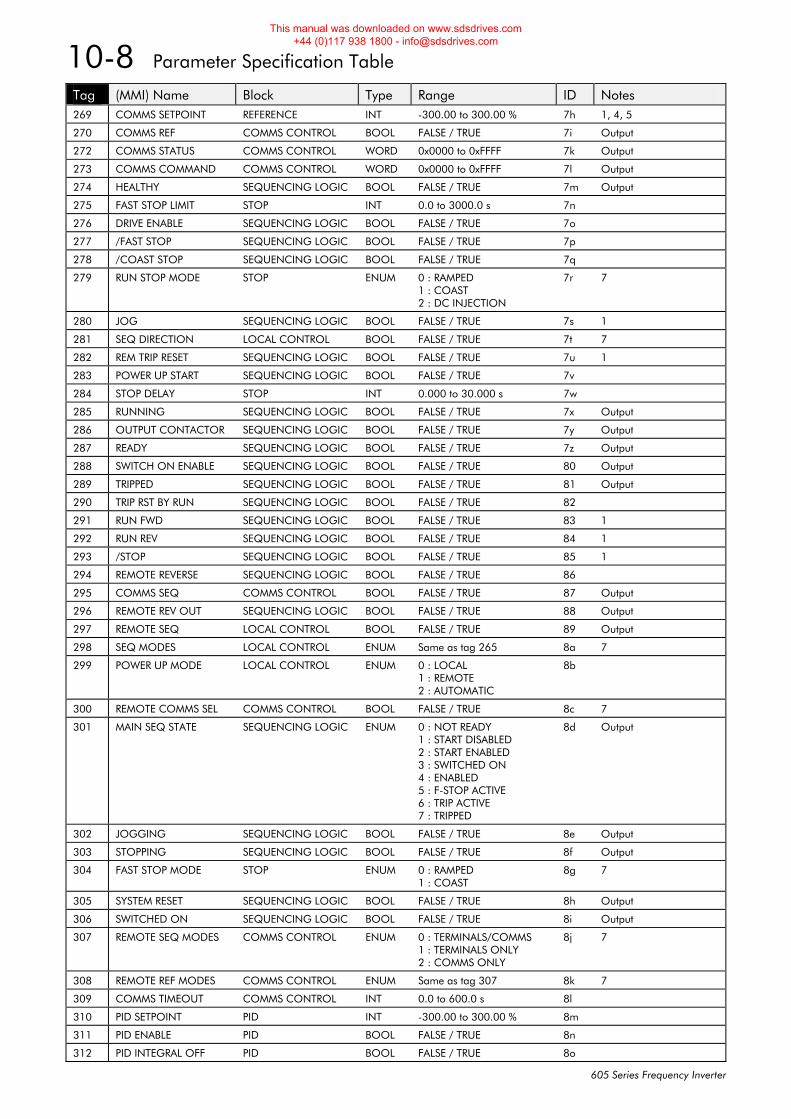
10-8 Parameter Specification Table
605 Series Frequency Inverter
Tag (MMI) Name Block Type Range ID Notes 269 COMMS SETPOINT REFERENCE INT -300.00 to 300.00 % 7h 1, 4, 5
270 COMMS REF COMMS CONTROL BOOL FALSE / TRUE 7i Output
272 COMMS STATUS COMMS CONTROL WORD 0x0000 to 0xFFFF 7k Output
273 COMMS COMMAND COMMS CONTROL WORD 0x0000 to 0xFFFF 7l Output
274 HEALTHY SEQUENCING LOGIC BOOL FALSE / TRUE 7m Output
275 FAST STOP LIMIT STOP INT 0.0 to 3000.0 s 7n
276 DRIVE ENABLE SEQUENCING LOGIC BOOL FALSE / TRUE 7o
277 /FAST STOP SEQUENCING LOGIC BOOL FALSE / TRUE 7p
278 /COAST STOP SEQUENCING LOGIC BOOL FALSE / TRUE 7q
279 RUN STOP MODE STOP ENUM 0 : RAMPED 1 : COAST 2 : DC INJECTION
7r 7
280 JOG SEQUENCING LOGIC BOOL FALSE / TRUE 7s 1
281 SEQ DIRECTION LOCAL CONTROL BOOL FALSE / TRUE 7t 7
282 REM TRIP RESET SEQUENCING LOGIC BOOL FALSE / TRUE 7u 1
283 POWER UP START SEQUENCING LOGIC BOOL FALSE / TRUE 7v
284 STOP DELAY STOP INT 0.000 to 30.000 s 7w
285 RUNNING SEQUENCING LOGIC BOOL FALSE / TRUE 7x Output
286 OUTPUT CONTACTOR SEQUENCING LOGIC BOOL FALSE / TRUE 7y Output
287 READY SEQUENCING LOGIC BOOL FALSE / TRUE 7z Output
288 SWITCH ON ENABLE SEQUENCING LOGIC BOOL FALSE / TRUE 80 Output
289 TRIPPED SEQUENCING LOGIC BOOL FALSE / TRUE 81 Output
290 TRIP RST BY RUN SEQUENCING LOGIC BOOL FALSE / TRUE 82
291 RUN FWD SEQUENCING LOGIC BOOL FALSE / TRUE 83 1
292 RUN REV SEQUENCING LOGIC BOOL FALSE / TRUE 84 1
293 /STOP SEQUENCING LOGIC BOOL FALSE / TRUE 85 1
294 REMOTE REVERSE SEQUENCING LOGIC BOOL FALSE / TRUE 86
295 COMMS SEQ COMMS CONTROL BOOL FALSE / TRUE 87 Output
296 REMOTE REV OUT SEQUENCING LOGIC BOOL FALSE / TRUE 88 Output
297 REMOTE SEQ LOCAL CONTROL BOOL FALSE / TRUE 89 Output
298 SEQ MODES LOCAL CONTROL ENUM Same as tag 265 8a 7
299 POWER UP MODE LOCAL CONTROL ENUM 0 : LOCAL 1 : REMOTE 2 : AUTOMATIC
8b
300 REMOTE COMMS SEL COMMS CONTROL BOOL FALSE / TRUE 8c 7
301 MAIN SEQ STATE SEQUENCING LOGIC ENUM 0 : NOT READY 1 : START DISABLED 2 : START ENABLED 3 : SWITCHED ON 4 : ENABLED 5 : F-STOP ACTIVE 6 : TRIP ACTIVE 7 : TRIPPED
8d Output
302 JOGGING SEQUENCING LOGIC BOOL FALSE / TRUE 8e Output
303 STOPPING SEQUENCING LOGIC BOOL FALSE / TRUE 8f Output
304 FAST STOP MODE STOP ENUM 0 : RAMPED 1 : COAST
8g 7
305 SYSTEM RESET SEQUENCING LOGIC BOOL FALSE / TRUE 8h Output
306 SWITCHED ON SEQUENCING LOGIC BOOL FALSE / TRUE 8i Output
307 REMOTE SEQ MODES COMMS CONTROL ENUM 0 : TERMINALS/COMMS 1 : TERMINALS ONLY 2 : COMMS ONLY
8j 7
308 REMOTE REF MODES COMMS CONTROL ENUM Same as tag 307 8k 7
309 COMMS TIMEOUT COMMS CONTROL INT 0.0 to 600.0 s 8l
310 PID SETPOINT PID INT -300.00 to 300.00 % 8m
311 PID ENABLE PID BOOL FALSE / TRUE 8n
312 PID INTEGRAL OFF PID BOOL FALSE / TRUE 8o
This manual was downloaded on www.sdsdrives.com +44 (0)117 938 1800 - [email protected]
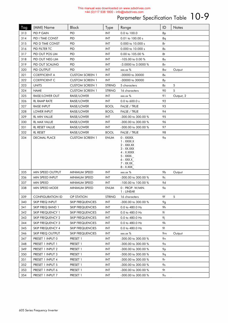
Parameter Specification Table 10-9
605 Series Frequency Inverter
Tag (MMI) Name Block Type Range ID Notes 313 PID P GAIN PID INT 0.0 to 100.0 8p
314 PID I TIME CONST PID INT 0.01 to 100.00 s 8q
315 PID D TIME CONST PID INT 0.000 to 10.000 s 8r
316 PID FILTER TC PID INT 0.000 to 10.000 s 8s
317 PID OUT POS LIM PID INT 0.00 to 105.00 % 8t
318 PID OUT NEG LIM PID INT -105.00 to 0.00 % 8u
319 PID OUT SCALING PID INT -3.0000 to 3.0000 % 8v
320 PID OUTPUT PID INT xxx.xx % 8w Output
321 COEFFICIENT A CUSTOM SCREEN 1 INT -30000 to 30000 8x
322 COEFFICIENT C CUSTOM SCREEN 1 INT -30000 to 30000 8y
323 UNITS CUSTOM SCREEN 1 STRING 5 characters 8z 5
324 NAME CUSTOM SCREEN 1 STRING 16 characters 90 5
325 RAISE/LOWER OUT RAISE/LOWER INT xxx.xx % 91 Output, 2
326 RL RAMP RATE RAISE/LOWER INT 0.0 to 600.0 s 92
327 RAISE INPUT RAISE/LOWER BOOL FALSE / TRUE 93
328 LOWER INPUT RAISE/LOWER BOOL FALSE / TRUE 94
329 RL MIN VALUE RAISE/LOWER INT -300.00 to 300.00 % 95
330 RL MAX VALUE RAISE/LOWER INT -300.00 to 300.00 % 96
331 RL RESET VALUE RAISE/LOWER INT -300.00 to 300.00 % 97
332 RL RESET RAISE/LOWER BOOL FALSE / TRUE 98
334 DECIMAL PLACE CUSTOM SCREEN 1 ENUM 0 : XXXXX. 1 : XXXX.X 2 : XXX.XX 3 : XX.XXX 4 : X.XXXX 5 : XXXX._ 6 : XXX.X_ 7 : XX.XX_ 8 : X.XXX_
9a
335 MIN SPEED OUTPUT MINIMUM SPEED INT xxx.xx % 9b Output
336 MIN SPEED INPUT MINIMUM SPEED INT -300.00 to 300.00 % 9c
337 MIN SPEED MINIMUM SPEED INT -100.00 to 100.00 % 9d
338 MIN SPEED MODE MINIMUM SPEED ENUM 0 : PROP. W/MIN. 1 : LINEAR
9e
339 CONFIGURATION ID OP STATION STRING 16 characters 9f 5
340 SKIP FREQ INPUT SKIP FREQUENCIES INT -300.00 to 300.00 % 9g
341 SKIP FREQ BAND 1 SKIP FREQUENCIES INT 0.0 to 480.0 Hz 9h
342 SKIP FREQUENCY 1 SKIP FREQUENCIES INT 0.0 to 480.0 Hz 9i
343 SKIP FREQUENCY 2 SKIP FREQUENCIES INT 0.0 to 480.0 Hz 9j
344 SKIP FREQUENCY 3 SKIP FREQUENCIES INT 0.0 to 480.0 Hz 9k
345 SKIP FREQUENCY 4 SKIP FREQUENCIES INT 0.0 to 480.0 Hz 9l
346 SKIP FREQ OUTPUT SKIP FREQUENCIES INT xxx.xx % 9m Output
347 PRESET 1 INPUT 0 PRESET 1 INT -300.00 to 300.00 % 9n
348 PRESET 1 INPUT 1 PRESET 1 INT -300.00 to 300.00 % 9o
349 PRESET 1 INPUT 2 PRESET 1 INT -300.00 to 300.00 % 9p
350 PRESET 1 INPUT 3 PRESET 1 INT -300.00 to 300.00 % 9q
351 PRESET 1 INPUT 4 PRESET 1 INT -300.00 to 300.00 % 9r
352 PRESET 1 INPUT 5 PRESET 1 INT -300.00 to 300.00 % 9s
353 PRESET 1 INPUT 6 PRESET 1 INT -300.00 to 300.00 % 9t
354 PRESET 1 INPUT 7 PRESET 1 INT -300.00 to 300.00 % 9u
This manual was downloaded on www.sdsdrives.com +44 (0)117 938 1800 - [email protected]
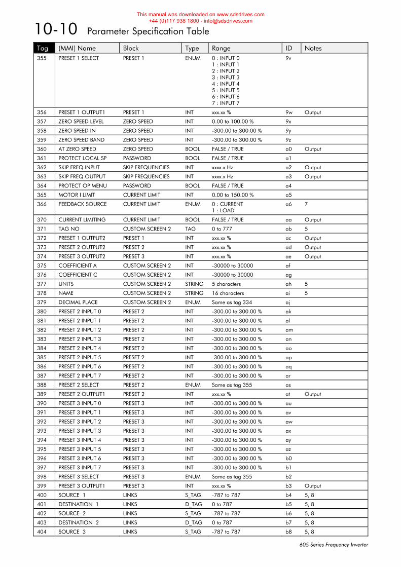
10-10 Parameter Specification Table
605 Series Frequency Inverter
Tag (MMI) Name Block Type Range ID Notes 355 PRESET 1 SELECT PRESET 1 ENUM 0 : INPUT 0
1 : INPUT 1 2 : INPUT 2 3 : INPUT 3 4 : INPUT 4 5 : INPUT 5 6 : INPUT 6 7 : INPUT 7
9v
356 PRESET 1 OUTPUT1 PRESET 1 INT xxx.xx % 9w Output
357 ZERO SPEED LEVEL ZERO SPEED INT 0.00 to 100.00 % 9x
358 ZERO SPEED IN ZERO SPEED INT -300.00 to 300.00 % 9y
359 ZERO SPEED BAND ZERO SPEED INT -300.00 to 300.00 % 9z
360 AT ZERO SPEED ZERO SPEED BOOL FALSE / TRUE a0 Output
361 PROTECT LOCAL SP PASSWORD BOOL FALSE / TRUE a1
362 SKIP FREQ INPUT SKIP FREQUENCIES INT xxxx.x Hz a2 Output
363 SKIP FREQ OUTPUT SKIP FREQUENCIES INT xxxx.x Hz a3 Output
364 PROTECT OP MENU PASSWORD BOOL FALSE / TRUE a4
365 MOTOR I LIMIT CURRENT LIMIT INT 0.00 to 150.00 % a5
366 FEEDBACK SOURCE CURRENT LIMIT ENUM 0 : CURRENT 1 : LOAD
a6 7
370 CURRENT LIMITING CURRENT LIMIT BOOL FALSE / TRUE aa Output
371 TAG NO CUSTOM SCREEN 2 TAG 0 to 777 ab 5
372 PRESET 1 OUTPUT2 PRESET 1 INT xxx.xx % ac Output
373 PRESET 2 OUTPUT2 PRESET 2 INT xxx.xx % ad Output
374 PRESET 3 OUTPUT2 PRESET 3 INT xxx.xx % ae Output
375 COEFFICIENT A CUSTOM SCREEN 2 INT -30000 to 30000 af
376 COEFFICIENT C CUSTOM SCREEN 2 INT -30000 to 30000 ag
377 UNITS CUSTOM SCREEN 2 STRING 5 characters ah 5
378 NAME CUSTOM SCREEN 2 STRING 16 characters ai 5
379 DECIMAL PLACE CUSTOM SCREEN 2 ENUM Same as tag 334 aj
380 PRESET 2 INPUT 0 PRESET 2 INT -300.00 to 300.00 % ak
381 PRESET 2 INPUT 1 PRESET 2 INT -300.00 to 300.00 % al
382 PRESET 2 INPUT 2 PRESET 2 INT -300.00 to 300.00 % am
383 PRESET 2 INPUT 3 PRESET 2 INT -300.00 to 300.00 % an
384 PRESET 2 INPUT 4 PRESET 2 INT -300.00 to 300.00 % ao
385 PRESET 2 INPUT 5 PRESET 2 INT -300.00 to 300.00 % ap
386 PRESET 2 INPUT 6 PRESET 2 INT -300.00 to 300.00 % aq
387 PRESET 2 INPUT 7 PRESET 2 INT -300.00 to 300.00 % ar
388 PRESET 2 SELECT PRESET 2 ENUM Same as tag 355 as
389 PRESET 2 OUTPUT1 PRESET 2 INT xxx.xx % at Output
390 PRESET 3 INPUT 0 PRESET 3 INT -300.00 to 300.00 % au
391 PRESET 3 INPUT 1 PRESET 3 INT -300.00 to 300.00 % av
392 PRESET 3 INPUT 2 PRESET 3 INT -300.00 to 300.00 % aw
393 PRESET 3 INPUT 3 PRESET 3 INT -300.00 to 300.00 % ax
394 PRESET 3 INPUT 4 PRESET 3 INT -300.00 to 300.00 % ay
395 PRESET 3 INPUT 5 PRESET 3 INT -300.00 to 300.00 % az
396 PRESET 3 INPUT 6 PRESET 3 INT -300.00 to 300.00 % b0
397 PRESET 3 INPUT 7 PRESET 3 INT -300.00 to 300.00 % b1
398 PRESET 3 SELECT PRESET 3 ENUM Same as tag 355 b2
399 PRESET 3 OUTPUT1 PRESET 3 INT xxx.xx % b3 Output
400 SOURCE 1 LINKS S_TAG -787 to 787 b4 5, 8
401 DESTINATION 1 LINKS D_TAG 0 to 787 b5 5, 8
402 SOURCE 2 LINKS S_TAG -787 to 787 b6 5, 8
403 DESTINATION 2 LINKS D_TAG 0 to 787 b7 5, 8
404 SOURCE 3 LINKS S_TAG -787 to 787 b8 5, 8
This manual was downloaded on www.sdsdrives.com +44 (0)117 938 1800 - [email protected]
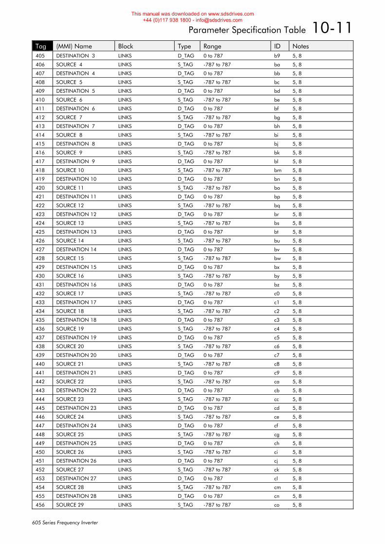
Parameter Specification Table 10-11
605 Series Frequency Inverter
Tag (MMI) Name Block Type Range ID Notes 405 DESTINATION 3 LINKS D_TAG 0 to 787 b9 5, 8
406 SOURCE 4 LINKS S_TAG -787 to 787 ba 5, 8
407 DESTINATION 4 LINKS D_TAG 0 to 787 bb 5, 8
408 SOURCE 5 LINKS S_TAG -787 to 787 bc 5, 8
409 DESTINATION 5 LINKS D_TAG 0 to 787 bd 5, 8
410 SOURCE 6 LINKS S_TAG -787 to 787 be 5, 8
411 DESTINATION 6 LINKS D_TAG 0 to 787 bf 5, 8
412 SOURCE 7 LINKS S_TAG -787 to 787 bg 5, 8
413 DESTINATION 7 LINKS D_TAG 0 to 787 bh 5, 8
414 SOURCE 8 LINKS S_TAG -787 to 787 bi 5, 8
415 DESTINATION 8 LINKS D_TAG 0 to 787 bj 5, 8
416 SOURCE 9 LINKS S_TAG -787 to 787 bk 5, 8
417 DESTINATION 9 LINKS D_TAG 0 to 787 bl 5, 8
418 SOURCE 10 LINKS S_TAG -787 to 787 bm 5, 8
419 DESTINATION 10 LINKS D_TAG 0 to 787 bn 5, 8
420 SOURCE 11 LINKS S_TAG -787 to 787 bo 5, 8
421 DESTINATION 11 LINKS D_TAG 0 to 787 bp 5, 8
422 SOURCE 12 LINKS S_TAG -787 to 787 bq 5, 8
423 DESTINATION 12 LINKS D_TAG 0 to 787 br 5, 8
424 SOURCE 13 LINKS S_TAG -787 to 787 bs 5, 8
425 DESTINATION 13 LINKS D_TAG 0 to 787 bt 5, 8
426 SOURCE 14 LINKS S_TAG -787 to 787 bu 5, 8
427 DESTINATION 14 LINKS D_TAG 0 to 787 bv 5, 8
428 SOURCE 15 LINKS S_TAG -787 to 787 bw 5, 8
429 DESTINATION 15 LINKS D_TAG 0 to 787 bx 5, 8
430 SOURCE 16 LINKS S_TAG -787 to 787 by 5, 8
431 DESTINATION 16 LINKS D_TAG 0 to 787 bz 5, 8
432 SOURCE 17 LINKS S_TAG -787 to 787 c0 5, 8
433 DESTINATION 17 LINKS D_TAG 0 to 787 c1 5, 8
434 SOURCE 18 LINKS S_TAG -787 to 787 c2 5, 8
435 DESTINATION 18 LINKS D_TAG 0 to 787 c3 5, 8
436 SOURCE 19 LINKS S_TAG -787 to 787 c4 5, 8
437 DESTINATION 19 LINKS D_TAG 0 to 787 c5 5, 8
438 SOURCE 20 LINKS S_TAG -787 to 787 c6 5, 8
439 DESTINATION 20 LINKS D_TAG 0 to 787 c7 5, 8
440 SOURCE 21 LINKS S_TAG -787 to 787 c8 5, 8
441 DESTINATION 21 LINKS D_TAG 0 to 787 c9 5, 8
442 SOURCE 22 LINKS S_TAG -787 to 787 ca 5, 8
443 DESTINATION 22 LINKS D_TAG 0 to 787 cb 5, 8
444 SOURCE 23 LINKS S_TAG -787 to 787 cc 5, 8
445 DESTINATION 23 LINKS D_TAG 0 to 787 cd 5, 8
446 SOURCE 24 LINKS S_TAG -787 to 787 ce 5, 8
447 DESTINATION 24 LINKS D_TAG 0 to 787 cf 5, 8
448 SOURCE 25 LINKS S_TAG -787 to 787 cg 5, 8
449 DESTINATION 25 LINKS D_TAG 0 to 787 ch 5, 8
450 SOURCE 26 LINKS S_TAG -787 to 787 ci 5, 8
451 DESTINATION 26 LINKS D_TAG 0 to 787 cj 5, 8
452 SOURCE 27 LINKS S_TAG -787 to 787 ck 5, 8
453 DESTINATION 27 LINKS D_TAG 0 to 787 cl 5, 8
454 SOURCE 28 LINKS S_TAG -787 to 787 cm 5, 8
455 DESTINATION 28 LINKS D_TAG 0 to 787 cn 5, 8
456 SOURCE 29 LINKS S_TAG -787 to 787 co 5, 8
This manual was downloaded on www.sdsdrives.com +44 (0)117 938 1800 - [email protected]
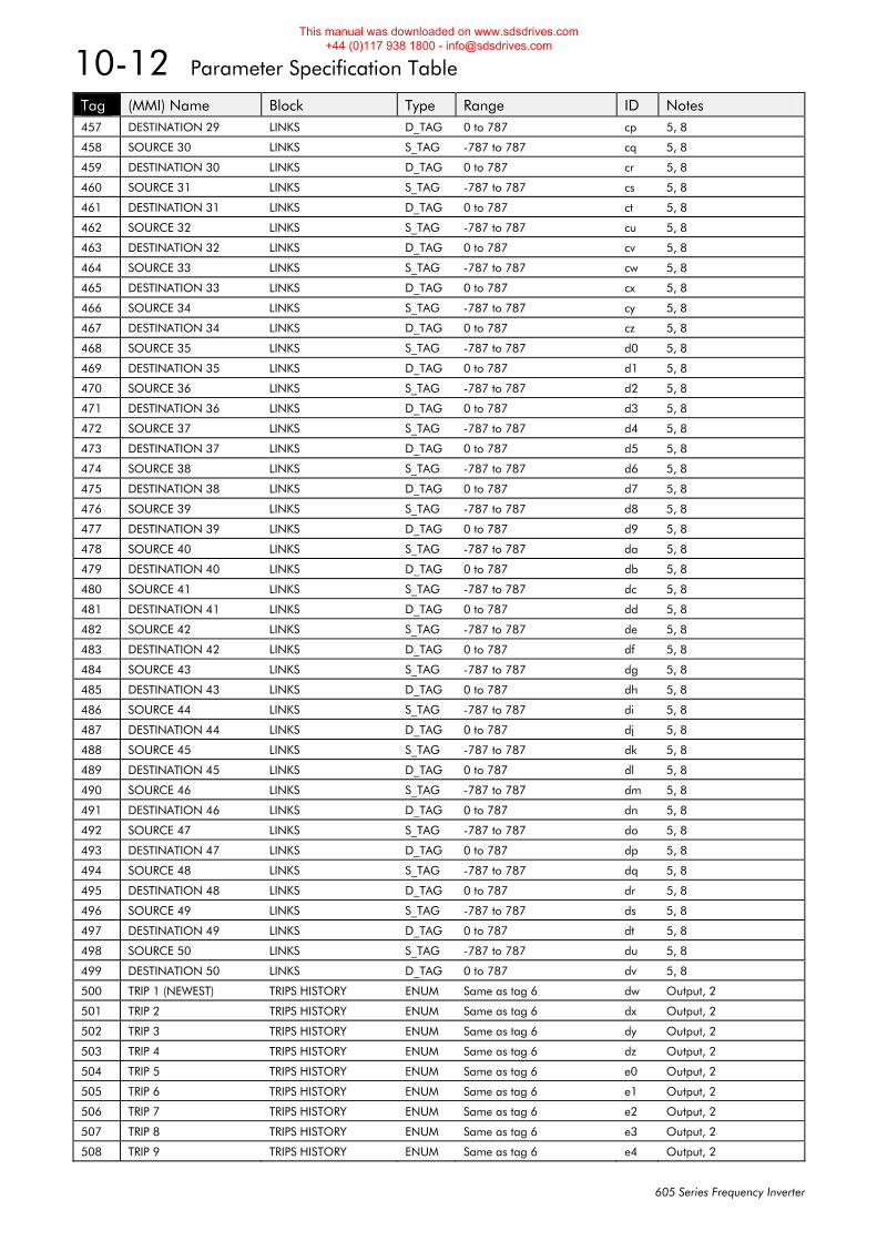
10-12 Parameter Specification Table
605 Series Frequency Inverter
Tag (MMI) Name Block Type Range ID Notes 457 DESTINATION 29 LINKS D_TAG 0 to 787 cp 5, 8
458 SOURCE 30 LINKS S_TAG -787 to 787 cq 5, 8
459 DESTINATION 30 LINKS D_TAG 0 to 787 cr 5, 8
460 SOURCE 31 LINKS S_TAG -787 to 787 cs 5, 8
461 DESTINATION 31 LINKS D_TAG 0 to 787 ct 5, 8
462 SOURCE 32 LINKS S_TAG -787 to 787 cu 5, 8
463 DESTINATION 32 LINKS D_TAG 0 to 787 cv 5, 8
464 SOURCE 33 LINKS S_TAG -787 to 787 cw 5, 8
465 DESTINATION 33 LINKS D_TAG 0 to 787 cx 5, 8
466 SOURCE 34 LINKS S_TAG -787 to 787 cy 5, 8
467 DESTINATION 34 LINKS D_TAG 0 to 787 cz 5, 8
468 SOURCE 35 LINKS S_TAG -787 to 787 d0 5, 8
469 DESTINATION 35 LINKS D_TAG 0 to 787 d1 5, 8
470 SOURCE 36 LINKS S_TAG -787 to 787 d2 5, 8
471 DESTINATION 36 LINKS D_TAG 0 to 787 d3 5, 8
472 SOURCE 37 LINKS S_TAG -787 to 787 d4 5, 8
473 DESTINATION 37 LINKS D_TAG 0 to 787 d5 5, 8
474 SOURCE 38 LINKS S_TAG -787 to 787 d6 5, 8
475 DESTINATION 38 LINKS D_TAG 0 to 787 d7 5, 8
476 SOURCE 39 LINKS S_TAG -787 to 787 d8 5, 8
477 DESTINATION 39 LINKS D_TAG 0 to 787 d9 5, 8
478 SOURCE 40 LINKS S_TAG -787 to 787 da 5, 8
479 DESTINATION 40 LINKS D_TAG 0 to 787 db 5, 8
480 SOURCE 41 LINKS S_TAG -787 to 787 dc 5, 8
481 DESTINATION 41 LINKS D_TAG 0 to 787 dd 5, 8
482 SOURCE 42 LINKS S_TAG -787 to 787 de 5, 8
483 DESTINATION 42 LINKS D_TAG 0 to 787 df 5, 8
484 SOURCE 43 LINKS S_TAG -787 to 787 dg 5, 8
485 DESTINATION 43 LINKS D_TAG 0 to 787 dh 5, 8
486 SOURCE 44 LINKS S_TAG -787 to 787 di 5, 8
487 DESTINATION 44 LINKS D_TAG 0 to 787 dj 5, 8
488 SOURCE 45 LINKS S_TAG -787 to 787 dk 5, 8
489 DESTINATION 45 LINKS D_TAG 0 to 787 dl 5, 8
490 SOURCE 46 LINKS S_TAG -787 to 787 dm 5, 8
491 DESTINATION 46 LINKS D_TAG 0 to 787 dn 5, 8
492 SOURCE 47 LINKS S_TAG -787 to 787 do 5, 8
493 DESTINATION 47 LINKS D_TAG 0 to 787 dp 5, 8
494 SOURCE 48 LINKS S_TAG -787 to 787 dq 5, 8
495 DESTINATION 48 LINKS D_TAG 0 to 787 dr 5, 8
496 SOURCE 49 LINKS S_TAG -787 to 787 ds 5, 8
497 DESTINATION 49 LINKS D_TAG 0 to 787 dt 5, 8
498 SOURCE 50 LINKS S_TAG -787 to 787 du 5, 8
499 DESTINATION 50 LINKS D_TAG 0 to 787 dv 5, 8
500 TRIP 1 (NEWEST) TRIPS HISTORY ENUM Same as tag 6 dw Output, 2
501 TRIP 2 TRIPS HISTORY ENUM Same as tag 6 dx Output, 2
502 TRIP 3 TRIPS HISTORY ENUM Same as tag 6 dy Output, 2
503 TRIP 4 TRIPS HISTORY ENUM Same as tag 6 dz Output, 2
504 TRIP 5 TRIPS HISTORY ENUM Same as tag 6 e0 Output, 2
505 TRIP 6 TRIPS HISTORY ENUM Same as tag 6 e1 Output, 2
506 TRIP 7 TRIPS HISTORY ENUM Same as tag 6 e2 Output, 2
507 TRIP 8 TRIPS HISTORY ENUM Same as tag 6 e3 Output, 2
508 TRIP 9 TRIPS HISTORY ENUM Same as tag 6 e4 Output, 2
This manual was downloaded on www.sdsdrives.com +44 (0)117 938 1800 - [email protected]
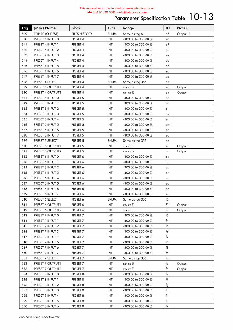
Parameter Specification Table 10-13
605 Series Frequency Inverter
Tag (MMI) Name Block Type Range ID Notes 509 TRIP 10 (OLDEST) TRIPS HISTORY ENUM Same as tag 6 e5 Output, 2
510 PRESET 4 INPUT 0 PRESET 4 INT -300.00 to 300.00 % e6
511 PRESET 4 INPUT 1 PRESET 4 INT -300.00 to 300.00 % e7
512 PRESET 4 INPUT 2 PRESET 4 INT -300.00 to 300.00 % e8
513 PRESET 4 INPUT 3 PRESET 4 INT -300.00 to 300.00 % e9
514 PRESET 4 INPUT 4 PRESET 4 INT -300.00 to 300.00 % ea
515 PRESET 4 INPUT 5 PRESET 4 INT -300.00 to 300.00 % eb
516 PRESET 4 INPUT 6 PRESET 4 INT -300.00 to 300.00 % ec
517 PRESET 4 INPUT 7 PRESET 4 INT -300.00 to 300.00 % ed
518 PRESET 4 SELECT PRESET 4 ENUM Same as tag 355 ee
519 PRESET 4 OUTPUT1 PRESET 4 INT xxx.xx % ef Output
520 PRESET 4 OUTPUT2 PRESET 4 INT xxx.xx % eg Output
521 PRESET 5 INPUT 0 PRESET 5 INT -300.00 to 300.00 % eh
522 PRESET 5 INPUT 1 PRESET 5 INT -300.00 to 300.00 % ei
523 PRESET 5 INPUT 2 PRESET 5 INT -300.00 to 300.00 % ej
524 PRESET 5 INPUT 3 PRESET 5 INT -300.00 to 300.00 % ek
525 PRESET 5 INPUT 4 PRESET 5 INT -300.00 to 300.00 % el
526 PRESET 5 INPUT 5 PRESET 5 INT -300.00 to 300.00 % em
527 PRESET 5 INPUT 6 PRESET 5 INT -300.00 to 300.00 % en
528 PRESET 5 INPUT 7 PRESET 5 INT -300.00 to 300.00 % eo
529 PRESET 5 SELECT PRESET 5 ENUM Same as tag 355 ep
530 PRESET 5 OUTPUT1 PRESET 5 INT xxx.xx % eq Output
531 PRESET 5 OUTPUT2 PRESET 5 INT xxx.xx % er Output
532 PRESET 6 INPUT 0 PRESET 6 INT -300.00 to 300.00 % es
533 PRESET 6 INPUT 1 PRESET 6 INT -300.00 to 300.00 % et
534 PRESET 6 INPUT 2 PRESET 6 INT -300.00 to 300.00 % eu
535 PRESET 6 INPUT 3 PRESET 6 INT -300.00 to 300.00 % ev
536 PRESET 6 INPUT 4 PRESET 6 INT -300.00 to 300.00 % ew
537 PRESET 6 INPUT 5 PRESET 6 INT -300.00 to 300.00 % ex
538 PRESET 6 INPUT 6 PRESET 6 INT -300.00 to 300.00 % ey
539 PRESET 6 INPUT 7 PRESET 6 INT -300.00 to 300.00 % ez
540 PRESET 6 SELECT PRESET 6 ENUM Same as tag 355 f0
541 PRESET 6 OUTPUT1 PRESET 6 INT xxx.xx % f1 Output
542 PRESET 6 OUTPUT2 PRESET 6 INT xxx.xx % f2 Output
543 PRESET 7 INPUT 0 PRESET 7 INT -300.00 to 300.00 % f3
544 PRESET 7 INPUT 1 PRESET 7 INT -300.00 to 300.00 % f4
545 PRESET 7 INPUT 2 PRESET 7 INT -300.00 to 300.00 % f5
546 PRESET 7 INPUT 3 PRESET 7 INT -300.00 to 300.00 % f6
547 PRESET 7 INPUT 4 PRESET 7 INT -300.00 to 300.00 % f7
548 PRESET 7 INPUT 5 PRESET 7 INT -300.00 to 300.00 % f8
549 PRESET 7 INPUT 6 PRESET 7 INT -300.00 to 300.00 % f9
550 PRESET 7 INPUT 7 PRESET 7 INT -300.00 to 300.00 % fa
551 PRESET 7 SELECT PRESET 7 ENUM Same as tag 355 fb
552 PRESET 7 OUTPUT1 PRESET 7 INT xxx.xx % fc Output
553 PRESET 7 OUTPUT2 PRESET 7 INT xxx.xx % fd Output
554 PRESET 8 INPUT 0 PRESET 8 INT -300.00 to 300.00 % fe
555 PRESET 8 INPUT 1 PRESET 8 INT -300.00 to 300.00 % ff
556 PRESET 8 INPUT 2 PRESET 8 INT -300.00 to 300.00 % fg
557 PRESET 8 INPUT 3 PRESET 8 INT -300.00 to 300.00 % fh
558 PRESET 8 INPUT 4 PRESET 8 INT -300.00 to 300.00 % fi
559 PRESET 8 INPUT 5 PRESET 8 INT -300.00 to 300.00 % fj
560 PRESET 8 INPUT 6 PRESET 8 INT -300.00 to 300.00 % fk
This manual was downloaded on www.sdsdrives.com +44 (0)117 938 1800 - [email protected]
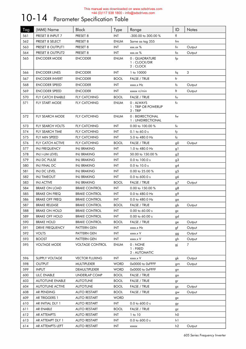
10-14 Parameter Specification Table
605 Series Frequency Inverter
Tag (MMI) Name Block Type Range ID Notes 561 PRESET 8 INPUT 7 PRESET 8 INT -300.00 to 300.00 % fl
562 PRESET 8 SELECT PRESET 8 ENUM Same as tag 355 fm
563 PRESET 8 OUTPUT1 PRESET 8 INT xxx.xx % fn Output
564 PRESET 8 OUTPUT2 PRESET 8 INT xxx.xx % fo Output
565 ENCODER MODE ENCODER ENUM 0 : QUADRATURE 1 : CLOCK/DIR 2 : CLOCK
fp
566 ENCODER LINES ENCODER INT 1 to 10000 fq 3
567 ENCODER INVERT ENCODER BOOL FALSE / TRUE fr
568 ENCODER SPEED ENCODER INT xxxx.x Hz fs Output
569 ENCODER SPEED ENCODER INT xxxxx n/min ft Output
570 FLY CATCH ENABLE FLY CATCHING BOOL FALSE / TRUE fu
571 FLY START MODE FLY CATCHING ENUM 0 : ALWAYS 1 : TRIP OR POWERUP 2 : TRIP
fv
572 FLY SEARCH MODE FLY CATCHING ENUM 0 : BIDIRECTIONAL 1 : UNIDIRECTIONAL
fw
573 FLY SEARCH VOLTS FLY CATCHING INT 0.00 to 100.00 % fx
574 FLY SEARCH TIME FLY CATCHING INT 0.1 to 60.0 s fy
575 FLY MIN SPEED FLY CATCHING INT 5.0 to 480.0 Hz fz
576 FLY CATCH ACTIVE FLY CATCHING BOOL FALSE / TRUE g0 Output
577 INJ FREQUENCY INJ BRAKING INT 1.0 to 480.0 Hz g1
578 INJ I-LIM LEVEL INJ BRAKING INT 50.00 to 150.00 % g2
579 INJ DC PULSE INJ BRAKING INT 0.0 to 100.0 s g3
580 INJ FINAL DC INJ BRAKING INT 0.0 to 10.0 s g4
581 INJ DC LEVEL INJ BRAKING INT 0.00 to 25.00 % g5
582 INJ TIMEOUT INJ BRAKING INT 0.0 to 600.0 s g6
583 INJ ACTIVE INJ BRAKING BOOL FALSE / TRUE g7 Output
584 BRAKE ON LOAD BRAKE CONTROL INT 0.00 to 150.00 % g8
585 BRAKE ON FREQ BRAKE CONTROL INT 0.0 to 480.0 Hz g9
586 BRAKE OFF FREQ BRAKE CONTROL INT 0.0 to 480.0 Hz ga
587 BRAKE RELEASE BRAKE CONTROL BOOL FALSE / TRUE gb Output
588 BRAKE ON HOLD BRAKE CONTROL INT 0.00 to 60.00 s gc
589 BRAKE OFF HOLD BRAKE CONTROL INT 0.00 to 60.00 s gd
590 BRAKE HOLD BRAKE CONTROL BOOL FALSE / TRUE ge Output
591 DRIVE FREQUENCY PATTERN GEN INT xxxx.x Hz gf Output
592 VOLTS PATTERN GEN INT xxxx.x V gg Output
593 BOOST PATTERN GEN INT xxxx.x V gh Output
595 VOLTAGE MODE VOLTAGE CONTROL ENUM 0 : NONE 1 : FIXED 2 : AUTOMATIC
gj 7
596 SUPPLY VOLTAGE VECTOR FLUXING INT xxxx.x V gk Output
598 OUTPUT MULTIPLEXER WORD 0x0000 to 0xFFFF gm Output
599 INPUT DEMULTIPLEXER WORD 0x0000 to 0xFFFF gn
600 ULC ENABLE UNDERLAP COMP BOOL FALSE / TRUE go
603 AUTOTUNE ENABLE AUTOTUNE BOOL FALSE / TRUE gr
604 AUTOTUNE ACTIVE AUTOTUNE BOOL FALSE / TRUE gs Output
608 AR PENDING AUTO RESTART BOOL FALSE / TRUE gw Output
609 AR TRIGGERS 1 AUTO RESTART WORD gx
610 AR INITIAL DLY 1 AUTO RESTART INT 0.0 to 600.0 s gy
611 AR ENABLE AUTO RESTART BOOL FALSE / TRUE gz
612 AR ATTEMPTS AUTO RESTART INT 1 to 10 h0
613 AR ATTEMPT DLY 1 AUTO RESTART INT 0.0 to 600.0 s h1
614 AR ATTEMPTS LEFT AUTO RESTART INT xxxxx h2 Output
This manual was downloaded on www.sdsdrives.com +44 (0)117 938 1800 - [email protected]
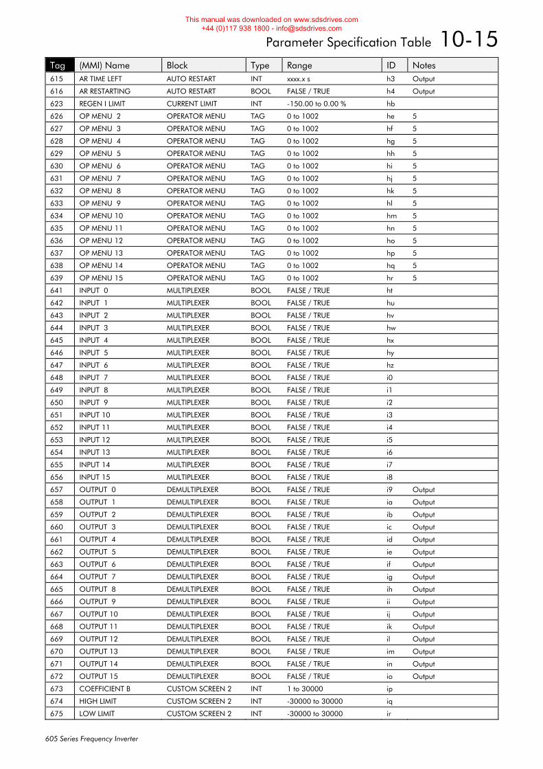
Parameter Specification Table 10-15
605 Series Frequency Inverter
Tag (MMI) Name Block Type Range ID Notes 615 AR TIME LEFT AUTO RESTART INT xxxx.x s h3 Output
616 AR RESTARTING AUTO RESTART BOOL FALSE / TRUE h4 Output
623 REGEN I LIMIT CURRENT LIMIT INT -150.00 to 0.00 % hb
626 OP MENU 2 OPERATOR MENU TAG 0 to 1002 he 5
627 OP MENU 3 OPERATOR MENU TAG 0 to 1002 hf 5
628 OP MENU 4 OPERATOR MENU TAG 0 to 1002 hg 5
629 OP MENU 5 OPERATOR MENU TAG 0 to 1002 hh 5
630 OP MENU 6 OPERATOR MENU TAG 0 to 1002 hi 5
631 OP MENU 7 OPERATOR MENU TAG 0 to 1002 hj 5
632 OP MENU 8 OPERATOR MENU TAG 0 to 1002 hk 5
633 OP MENU 9 OPERATOR MENU TAG 0 to 1002 hl 5
634 OP MENU 10 OPERATOR MENU TAG 0 to 1002 hm 5
635 OP MENU 11 OPERATOR MENU TAG 0 to 1002 hn 5
636 OP MENU 12 OPERATOR MENU TAG 0 to 1002 ho 5
637 OP MENU 13 OPERATOR MENU TAG 0 to 1002 hp 5
638 OP MENU 14 OPERATOR MENU TAG 0 to 1002 hq 5
639 OP MENU 15 OPERATOR MENU TAG 0 to 1002 hr 5
641 INPUT 0 MULTIPLEXER BOOL FALSE / TRUE ht
642 INPUT 1 MULTIPLEXER BOOL FALSE / TRUE hu
643 INPUT 2 MULTIPLEXER BOOL FALSE / TRUE hv
644 INPUT 3 MULTIPLEXER BOOL FALSE / TRUE hw
645 INPUT 4 MULTIPLEXER BOOL FALSE / TRUE hx
646 INPUT 5 MULTIPLEXER BOOL FALSE / TRUE hy
647 INPUT 6 MULTIPLEXER BOOL FALSE / TRUE hz
648 INPUT 7 MULTIPLEXER BOOL FALSE / TRUE i0
649 INPUT 8 MULTIPLEXER BOOL FALSE / TRUE i1
650 INPUT 9 MULTIPLEXER BOOL FALSE / TRUE i2
651 INPUT 10 MULTIPLEXER BOOL FALSE / TRUE i3
652 INPUT 11 MULTIPLEXER BOOL FALSE / TRUE i4
653 INPUT 12 MULTIPLEXER BOOL FALSE / TRUE i5
654 INPUT 13 MULTIPLEXER BOOL FALSE / TRUE i6
655 INPUT 14 MULTIPLEXER BOOL FALSE / TRUE i7
656 INPUT 15 MULTIPLEXER BOOL FALSE / TRUE i8
657 OUTPUT 0 DEMULTIPLEXER BOOL FALSE / TRUE i9 Output
658 OUTPUT 1 DEMULTIPLEXER BOOL FALSE / TRUE ia Output
659 OUTPUT 2 DEMULTIPLEXER BOOL FALSE / TRUE ib Output
660 OUTPUT 3 DEMULTIPLEXER BOOL FALSE / TRUE ic Output
661 OUTPUT 4 DEMULTIPLEXER BOOL FALSE / TRUE id Output
662 OUTPUT 5 DEMULTIPLEXER BOOL FALSE / TRUE ie Output
663 OUTPUT 6 DEMULTIPLEXER BOOL FALSE / TRUE if Output
664 OUTPUT 7 DEMULTIPLEXER BOOL FALSE / TRUE ig Output
665 OUTPUT 8 DEMULTIPLEXER BOOL FALSE / TRUE ih Output
666 OUTPUT 9 DEMULTIPLEXER BOOL FALSE / TRUE ii Output
667 OUTPUT 10 DEMULTIPLEXER BOOL FALSE / TRUE ij Output
668 OUTPUT 11 DEMULTIPLEXER BOOL FALSE / TRUE ik Output
669 OUTPUT 12 DEMULTIPLEXER BOOL FALSE / TRUE il Output
670 OUTPUT 13 DEMULTIPLEXER BOOL FALSE / TRUE im Output
671 OUTPUT 14 DEMULTIPLEXER BOOL FALSE / TRUE in Output
672 OUTPUT 15 DEMULTIPLEXER BOOL FALSE / TRUE io Output
673 COEFFICIENT B CUSTOM SCREEN 2 INT 1 to 30000 ip
674 HIGH LIMIT CUSTOM SCREEN 2 INT -30000 to 30000 iq
675 LOW LIMIT CUSTOM SCREEN 2 INT -30000 to 30000 ir
This manual was downloaded on www.sdsdrives.com +44 (0)117 938 1800 - [email protected]
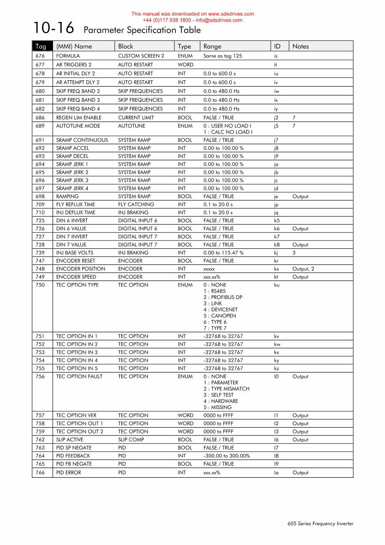
10-16 Parameter Specification Table
605 Series Frequency Inverter
Tag (MMI) Name Block Type Range ID Notes 676 FORMULA CUSTOM SCREEN 2 ENUM Same as tag 125 is
677 AR TRIGGERS 2 AUTO RESTART WORD it
678 AR INITIAL DLY 2 AUTO RESTART INT 0.0 to 600.0 s iu
679 AR ATTEMPT DLY 2 AUTO RESTART INT 0.0 to 600.0 s iv
680 SKIP FREQ BAND 2 SKIP FREQUENCIES INT 0.0 to 480.0 Hz iw
681 SKIP FREQ BAND 3 SKIP FREQUENCIES INT 0.0 to 480.0 Hz ix
682 SKIP FREQ BAND 4 SKIP FREQUENCIES INT 0.0 to 480.0 Hz iy
686 REGEN LIM ENABLE CURRENT LIMIT BOOL FALSE / TRUE j2 7
689 AUTOTUNE MODE AUTOTUNE ENUM 0 : USER NO LOAD I 1 : CALC NO LOAD I
j5 7
691 SRAMP CONTINUOUS SYSTEM RAMP BOOL FALSE / TRUE j7
692 SRAMP ACCEL SYSTEM RAMP INT 0.00 to 100.00 % j8
693 SRAMP DECEL SYSTEM RAMP INT 0.00 to 100.00 % j9
694 SRAMP JERK 1 SYSTEM RAMP INT 0.00 to 100.00 % ja
695 SRAMP JERK 2 SYSTEM RAMP INT 0.00 to 100.00 % jb
696 SRAMP JERK 3 SYSTEM RAMP INT 0.00 to 100.00 % jc
697 SRAMP JERK 4 SYSTEM RAMP INT 0.00 to 100.00 % jd
698 RAMPING SYSTEM RAMP BOOL FALSE / TRUE je Output
709 FLY REFLUX TIME FLY CATCHING INT 0.1 to 20.0 s jp
710 INJ DEFLUX TIME INJ BRAKING INT 0.1 to 20.0 s jq
725 DIN 6 INVERT DIGITAL INPUT 6 BOOL FALSE / TRUE k5
726 DIN 6 VALUE DIGITAL INPUT 6 BOOL FALSE / TRUE k6 Output
727 DIN 7 INVERT DIGITAL INPUT 7 BOOL FALSE / TRUE k7
728 DIN 7 VALUE DIGITAL INPUT 7 BOOL FALSE / TRUE k8 Output
739 INJ BASE VOLTS INJ BRAKING INT 0.00 to 115.47 % kj 3
747 ENCODER RESET ENCODER BOOL FALSE / TRUE kr
748 ENCODER POSITION ENCODER INT xxxxx ks Output, 2
749 ENCODER SPEED ENCODER INT xxx.xx% kt Output
750 TEC OPTION TYPE TEC OPTION ENUM 0 : NONE 1 : RS485 2 : PROFIBUS DP 3 : LINK 4 : DEVICENET 5 : CANOPEN 6 : TYPE 6 7 : TYPE 7
ku
751 TEC OPTION IN 1 TEC OPTION INT -32768 to 32767 kv
752 TEC OPTION IN 2 TEC OPTION INT -32768 to 32767 kw
753 TEC OPTION IN 3 TEC OPTION INT -32768 to 32767 kx
754 TEC OPTION IN 4 TEC OPTION INT -32768 to 32767 ky
755 TEC OPTION IN 5 TEC OPTION INT -32768 to 32767 kz
756 TEC OPTION FAULT TEC OPTION ENUM 0 : NONE 1 : PARAMETER 2 : TYPE MISMATCH 3 : SELF TEST 4 : HARDWARE 5 : MISSING
l0 Output
757 TEC OPTION VER TEC OPTION WORD 0000 to FFFF l1 Output
758 TEC OPTION OUT 1 TEC OPTION WORD 0000 to FFFF l2 Output
759 TEC OPTION OUT 2 TEC OPTION WORD 0000 to FFFF l3 Output
762 SLIP ACTIVE SLIP COMP BOOL FALSE / TRUE l6 Output
763 PID SP NEGATE PID BOOL FALSE / TRUE l7
764 PID FEEDBACK PID INT -300.00 to 300.00% l8
765 PID FB NEGATE PID BOOL FALSE / TRUE l9
766 PID ERROR PID INT xxx.xx% la Output
This manual was downloaded on www.sdsdrives.com +44 (0)117 938 1800 - [email protected]
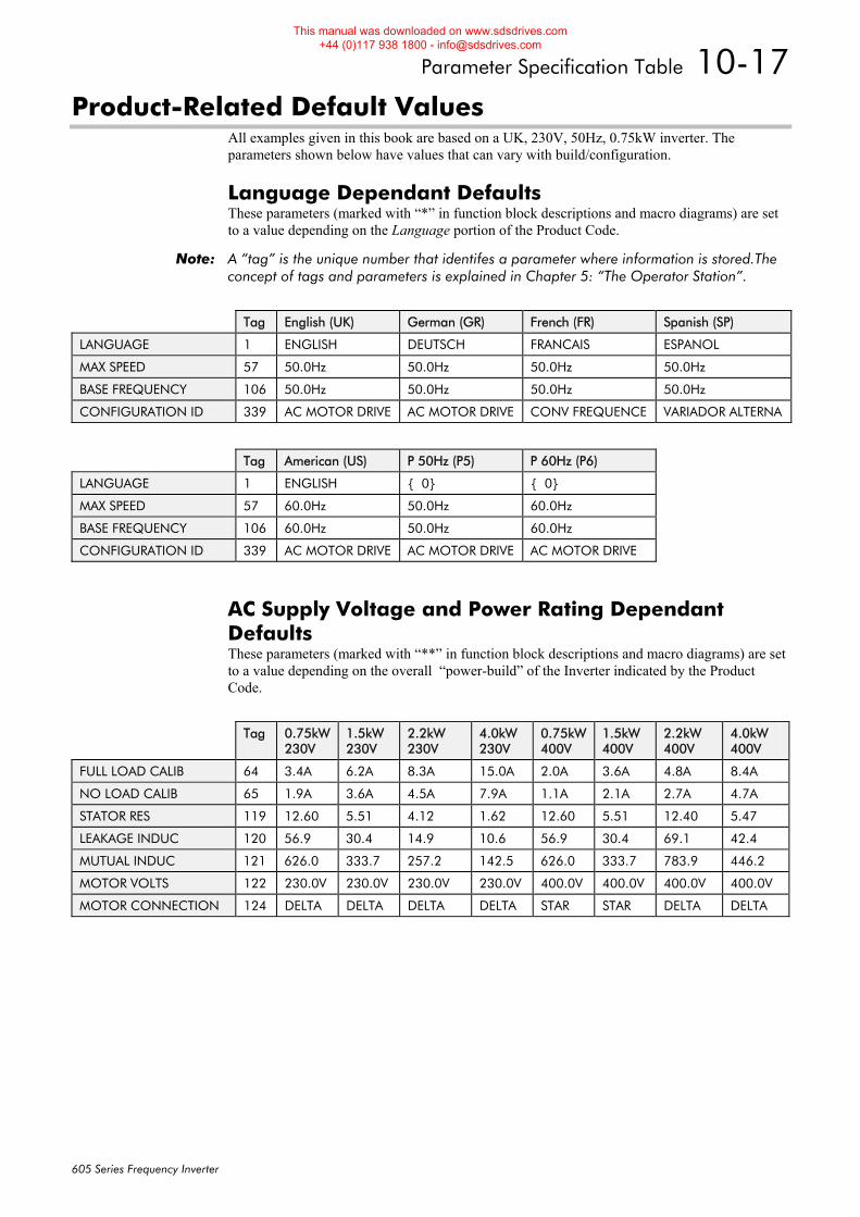
Parameter Specification Table 10-17
605 Series Frequency Inverter
Product-Related Default Values All examples given in this book are based on a UK, 230V, 50Hz, 0.75kW inverter. The parameters shown below have values that can vary with build/configuration.
Language Dependant Defaults These parameters (marked with “*” in function block descriptions and macro diagrams) are set to a value depending on the Language portion of the Product Code.
Note: A “tag” is the unique number that identifes a parameter where information is stored.The concept of tags and parameters is explained in Chapter 5: “The Operator Station”.
Tag English (UK) German (GR) French (FR) Spanish (SP)
LANGUAGE 1 ENGLISH DEUTSCH FRANCAIS ESPANOL
MAX SPEED 57 50.0Hz 50.0Hz 50.0Hz 50.0Hz
BASE FREQUENCY 106 50.0Hz 50.0Hz 50.0Hz 50.0Hz
CONFIGURATION ID 339 AC MOTOR DRIVE AC MOTOR DRIVE CONV FREQUENCE VARIADOR ALTERNA
Tag American (US) P 50Hz (P5) P 60Hz (P6)
LANGUAGE 1 ENGLISH { 0} { 0}
MAX SPEED 57 60.0Hz 50.0Hz 60.0Hz
BASE FREQUENCY 106 60.0Hz 50.0Hz 60.0Hz
CONFIGURATION ID 339 AC MOTOR DRIVE AC MOTOR DRIVE AC MOTOR DRIVE
AC Supply Voltage and Power Rating Dependant Defaults These parameters (marked with “**” in function block descriptions and macro diagrams) are set to a value depending on the overall “power-build” of the Inverter indicated by the Product Code.
Tag 0.75kW
230V 1.5kW 230V
2.2kW 230V
4.0kW 230V
0.75kW400V
1.5kW 400V
2.2kW 400V
4.0kW 400V
FULL LOAD CALIB 64 3.4A 6.2A 8.3A 15.0A 2.0A 3.6A 4.8A 8.4A
NO LOAD CALIB 65 1.9A 3.6A 4.5A 7.9A 1.1A 2.1A 2.7A 4.7A
STATOR RES 119 12.60 5.51 4.12 1.62 12.60 5.51 12.40 5.47
LEAKAGE INDUC 120 56.9 30.4 14.9 10.6 56.9 30.4 69.1 42.4
MUTUAL INDUC 121 626.0 333.7 257.2 142.5 626.0 333.7 783.9 446.2
MOTOR VOLTS 122 230.0V 230.0V 230.0V 230.0V 400.0V 400.0V 400.0V 400.0V
MOTOR CONNECTION 124 DELTA DELTA DELTA DELTA STAR STAR DELTA DELTA
This manual was downloaded on www.sdsdrives.com +44 (0)117 938 1800 - [email protected]

10-18 Parameter Specification Table
605 Series Frequency Inverter
This manual was downloaded on www.sdsdrives.com +44 (0)117 938 1800 - [email protected]
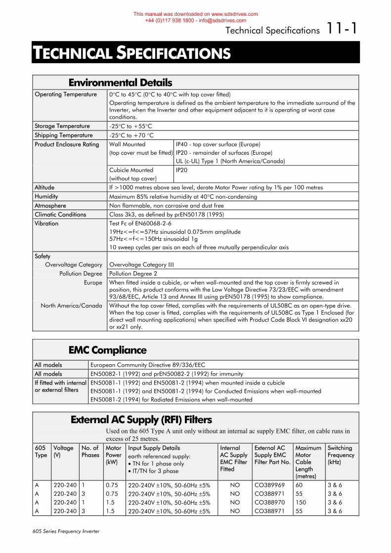
Technical Specifications 11-1
605 Series Frequency Inverter
11TECHNICAL SPECIFICATIONS
Environmental Details Operating Temperature 0°C to 45°C (0°C to 40°C with top cover fitted)
Operating temperature is defined as the ambient temperature to the immediate surround of the Inverter, when the Inverter and other equipment adjacent to it is operating at worst case conditions.
Storage Temperature -25°C to +55°C
Shipping Temperature -25°C to +70 °C
Product Enclosure Rating Wall Mounted (top cover must be fitted)
IP40 - top cover surface (Europe) IP20 - remainder of surfaces (Europe) UL (c-UL) Type 1 (North America/Canada)
Cubicle Mounted (without top cover)
IP20
Altitude If >1000 metres above sea level, derate Motor Power rating by 1% per 100 metres
Humidity Maximum 85% relative humidity at 40°C non-condensing
Atmosphere Non flammable, non corrosive and dust free
Climatic Conditions Class 3k3, as defined by prEN50178 (1995)
Vibration Test Fc of EN60068-2-6 19Hz<=f<=57Hz sinusoidal 0.075mm amplitude 57Hz<=f<=150Hz sinusoidal 1g 10 sweep cycles per axis on each of three mutually perpendicular axis
Safety Overvoltage Category Overvoltage Category III
Pollution Degree Pollution Degree 2
Europe When fitted inside a cubicle, or when wall-mounted and the top cover is firmly screwed in position, this product conforms with the Low Voltage Directive 73/23/EEC with amendment 93/68/EEC, Article 13 and Annex III using prEN50178 (1995) to show compliance.
North America/Canada Without the top cover fitted, complies with the requirements of UL508C as an open-type drive. When the top cover is fitted, complies with the requirements of UL508C as Type 1 Enclosed (for direct wall mounting applications) when specified with Product Code Block VI designation xx20 or xx21 only.
EMC Compliance All models European Community Directive 89/336/EEC
All models EN50082-1 (1992) and prEN50082-2 (1992) for immunity
If fitted with internal or external filters
EN50081-1 (1992) and EN50081-2 (1994) when mounted inside a cubicle EN50081-1 (1992) and EN50081-2 (1994) for Conducted Emissions when wall-mounted EN50081-2 (1994) for Radiated Emissions when wall-mounted
External AC Supply (RFI) Filters Used on the 605 Type A unit only without an internal ac supply EMC filter, on cable runs in excess of 25 metres.
605 Type
Voltage (V)
No. of Phases
Motor Power (kW)
Input Supply Details earth referenced supply: • TN for 1 phase only • IT/TN for 3 phase
Internal AC Supply EMC Filter Fitted
External AC Supply EMC Filter Part No.
Maximum Motor Cable Length (metres)
Switching Frequency (kHz)
A 220-240 1 0.75 220-240V ±10%, 50-60Hz ±5% NO CO389969 60 3 & 6 A 220-240 3 0.75 220-240V ±10%, 50-60Hz ±5% NO CO388971 55 3 & 6 A 220-240 1 1.5 220-240V ±10%, 50-60Hz ±5% NO CO388970 150 3 & 6 A 220-240 3 1.5 220-240V ±10%, 50-60Hz ±5% NO CO388971 55 3 & 6
This manual was downloaded on www.sdsdrives.com +44 (0)117 938 1800 - [email protected]
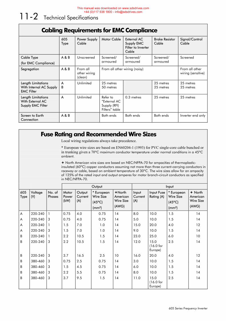
11-2 Technical Specifications
605 Series Frequency Inverter
Cabling Requirements for EMC Compliance 605
Type Power Supply Cable
Motor Cable External AC Supply EMC Filter to Inverter Cable
Brake Resistor Cable
Signal/Control Cable
Cable Type
(for EMC Compliance)
A & B Unscreened Screened/ armoured
Screened/ armoured
Screened/ armoured
Screened
Segregation A & B From all other wiring (clean)
From all other wiring (noisy) From all other wiring (sensitive)
Length Limitations With Internal AC Supply EMC Filter
A B
Unlimited 25 metres 50 metres
25 metres 25 metres
25 metres 25 metres
Length Limitations With External AC Supply EMC Filter
A
Unlimited Refer to “External AC Supply (RFI) Filters” table
0.3 metres 25 metres
25 metres
Screen to Earth Connection
A & B Both ends Both ends Both ends Inverter end only
Fuse Rating and Recommended Wire Sizes Local wiring regulations always take precedence.
* European wire sizes are based on EN60204-1 (1993) for PVC single-core cable bunched or in trunking given a 70ºC maximum conductor temperature under normal conditions in a 45ºC ambient.
North American wire sizes are based on NEC/NFPA-70 for ampacities of thermoplastic-insulated (60ºC) copper conductors assuming not more than three current-carrying conductors in raceway or cable, based on ambient temperature of 30ºC. The wire sizes allow for an ampacity of 125% of the rated input and output amperes for motor branch-circuit conductors as specified in NEC/NFPA-70.
Output Input
605 Type
Voltage (V)
No. of Phases
Motor Power (kW)
Output Current (A)
* European Wire Size
(45ºC)
(mm²)
North AmericanWire Size
(AWG)
Input Current (A)
Input Fuse Rating (A)
* European Wire Size
(45ºC)
(mm²)
North AmericanWire Size
(AWG)
A 220-240 1 0.75 4.0 0.75 14 8.0 10.0 1.5 14
A 220-240 3 0.75 4.0 0.75 14 5.0 10.0 1.5 14
A 220-240 1 1.5 7.0 1.0 14 15.0 20.0 4.0 12
A 220-240 3 1.5 7.0 1.0 14 9.0 10.0 1.5 14
B 220-240 1 2.2 10.5 1.5 14 23.0 25.0 6.0 10
B 220-240 3 2.2 10.5 1.5 14 12.0 15.0 (16.0 for Europe)
2.5 14
B 220-240 3 3.7 16.5 2.5 10 16.0 20.0 4.0 12
B 380-460 3 0.75 2.5 0.75 14 3.0 10.0 1.5 14
B 380-460 3 1.5 4.5 0.75 14 6.0 10.0 1.5 14
B 380-460 3 2.2 5.5 0.75 14 8.0 10.0 1.5 14
B 380-460 3 3.7 9.5 1.5 14 11.0 15.0 (16.0 for Europe)
2.5 14
This manual was downloaded on www.sdsdrives.com +44 (0)117 938 1800 - [email protected]
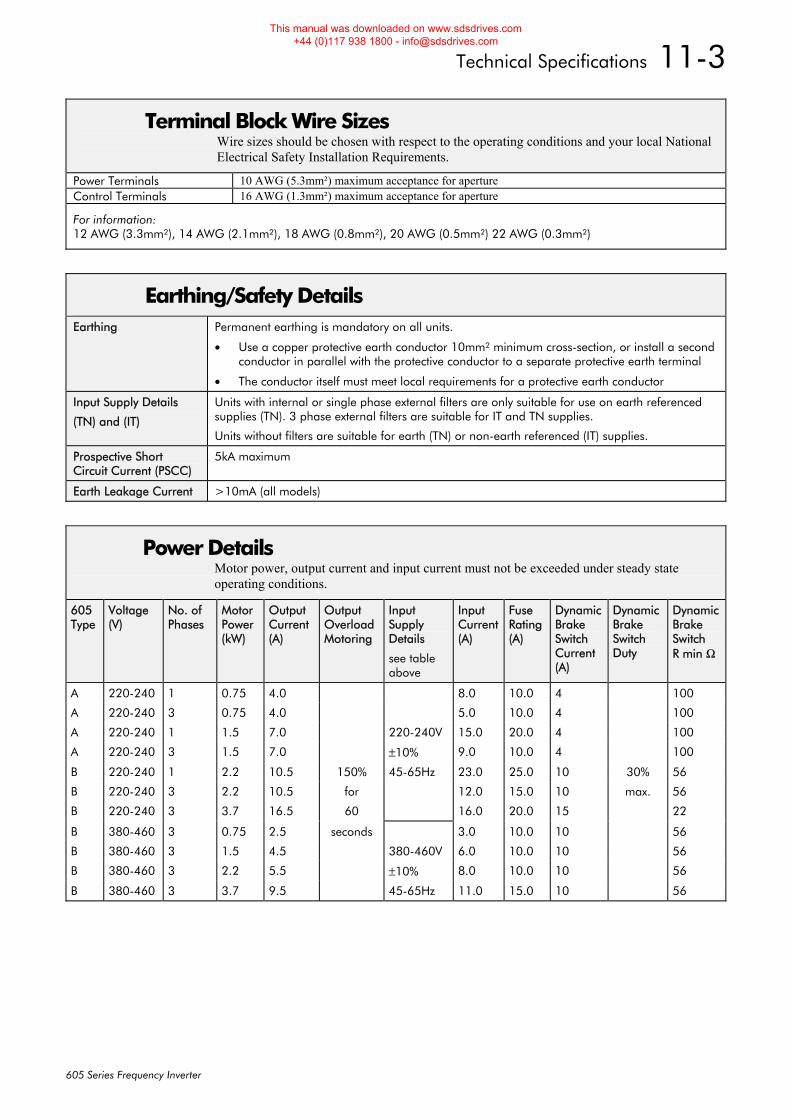
Technical Specifications 11-3
605 Series Frequency Inverter
Terminal Block Wire Sizes Wire sizes should be chosen with respect to the operating conditions and your local National Electrical Safety Installation Requirements.
Power Terminals 10 AWG (5.3mm²) maximum acceptance for aperture Control Terminals 16 AWG (1.3mm²) maximum acceptance for aperture
For information: 12 AWG (3.3mm²), 14 AWG (2.1mm²), 18 AWG (0.8mm²), 20 AWG (0.5mm²) 22 AWG (0.3mm²)
Earthing/Safety Details Earthing Permanent earthing is mandatory on all units.
• Use a copper protective earth conductor 10mm² minimum cross-section, or install a second conductor in parallel with the protective conductor to a separate protective earth terminal
• The conductor itself must meet local requirements for a protective earth conductor
Input Supply Details
(TN) and (IT)
Units with internal or single phase external filters are only suitable for use on earth referenced supplies (TN). 3 phase external filters are suitable for IT and TN supplies.
Units without filters are suitable for earth (TN) or non-earth referenced (IT) supplies.
Prospective Short Circuit Current (PSCC)
5kA maximum
Earth Leakage Current >10mA (all models)
Power Details Motor power, output current and input current must not be exceeded under steady state operating conditions.
605 Type
Voltage (V)
No. of Phases
Motor Power (kW)
Output Current (A)
Output Overload Motoring
Input Supply Details
see table above
Input Current (A)
Fuse Rating (A)
Dynamic Brake Switch Current (A)
Dynamic Brake Switch Duty
Dynamic Brake Switch R min Ω
A 220-240 1 0.75 4.0 8.0 10.0 4 100
A 220-240 3 0.75 4.0 5.0 10.0 4 100
A 220-240 1 1.5 7.0 220-240V 15.0 20.0 4 100
A 220-240 3 1.5 7.0 ±10% 9.0 10.0 4 100
B 220-240 1 2.2 10.5 150% 45-65Hz 23.0 25.0 10 30% 56
B 220-240 3 2.2 10.5 for 12.0 15.0 10 max. 56
B 220-240 3 3.7 16.5 60 16.0 20.0 15 22
B 380-460 3 0.75 2.5 seconds 3.0 10.0 10 56
B 380-460 3 1.5 4.5 380-460V 6.0 10.0 10 56
B 380-460 3 2.2 5.5 ±10% 8.0 10.0 10 56
B 380-460 3 3.7 9.5 45-65Hz 11.0 15.0 10 56
This manual was downloaded on www.sdsdrives.com +44 (0)117 938 1800 - [email protected]
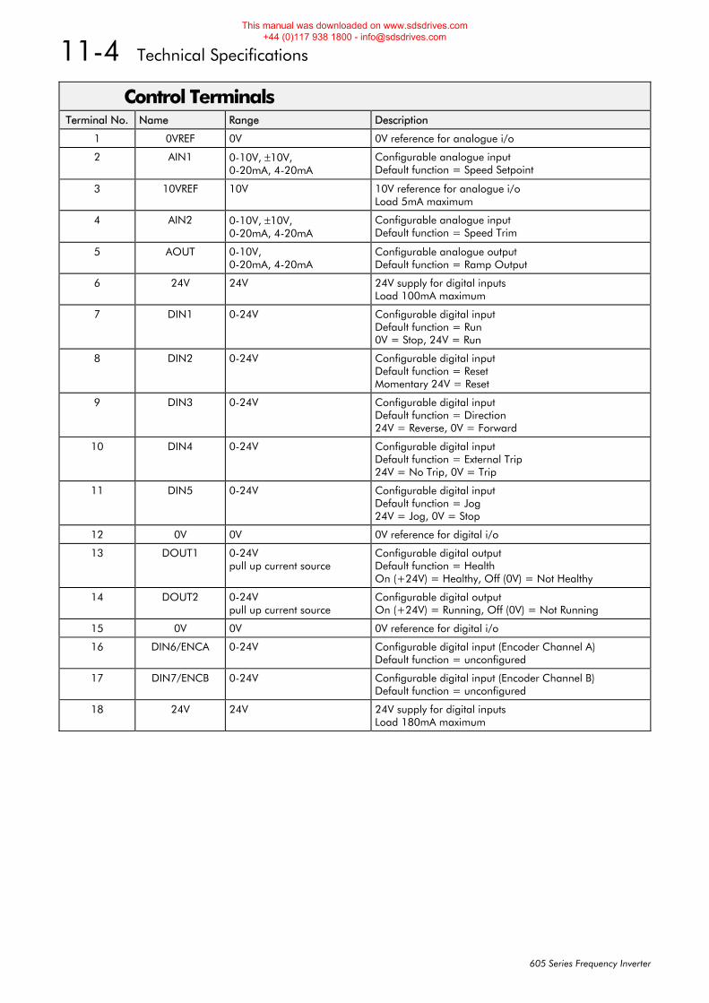
11-4 Technical Specifications
605 Series Frequency Inverter
Control Terminals Terminal No. Name Range Description
1 0VREF 0V 0V reference for analogue i/o
2 AIN1 0-10V, ±10V, 0-20mA, 4-20mA
Configurable analogue input Default function = Speed Setpoint
3 10VREF 10V 10V reference for analogue i/o Load 5mA maximum
4 AIN2 0-10V, ±10V, 0-20mA, 4-20mA
Configurable analogue input Default function = Speed Trim
5 AOUT 0-10V, 0-20mA, 4-20mA
Configurable analogue output Default function = Ramp Output
6 24V 24V 24V supply for digital inputs Load 100mA maximum
7 DIN1 0-24V Configurable digital input Default function = Run 0V = Stop, 24V = Run
8 DIN2 0-24V Configurable digital input Default function = Reset Momentary 24V = Reset
9 DIN3 0-24V Configurable digital input Default function = Direction 24V = Reverse, 0V = Forward
10 DIN4 0-24V Configurable digital input Default function = External Trip 24V = No Trip, 0V = Trip
11 DIN5 0-24V Configurable digital input Default function = Jog 24V = Jog, 0V = Stop
12 0V 0V 0V reference for digital i/o
13 DOUT1 0-24V pull up current source
Configurable digital output Default function = Health On (+24V) = Healthy, Off (0V) = Not Healthy
14 DOUT2 0-24V pull up current source
Configurable digital output On (+24V) = Running, Off (0V) = Not Running
15 0V 0V 0V reference for digital i/o
16 DIN6/ENCA 0-24V Configurable digital input (Encoder Channel A) Default function = unconfigured
17 DIN7/ENCB 0-24V Configurable digital input (Encoder Channel B) Default function = unconfigured
18 24V 24V 24V supply for digital inputs Load 180mA maximum
This manual was downloaded on www.sdsdrives.com +44 (0)117 938 1800 - [email protected]
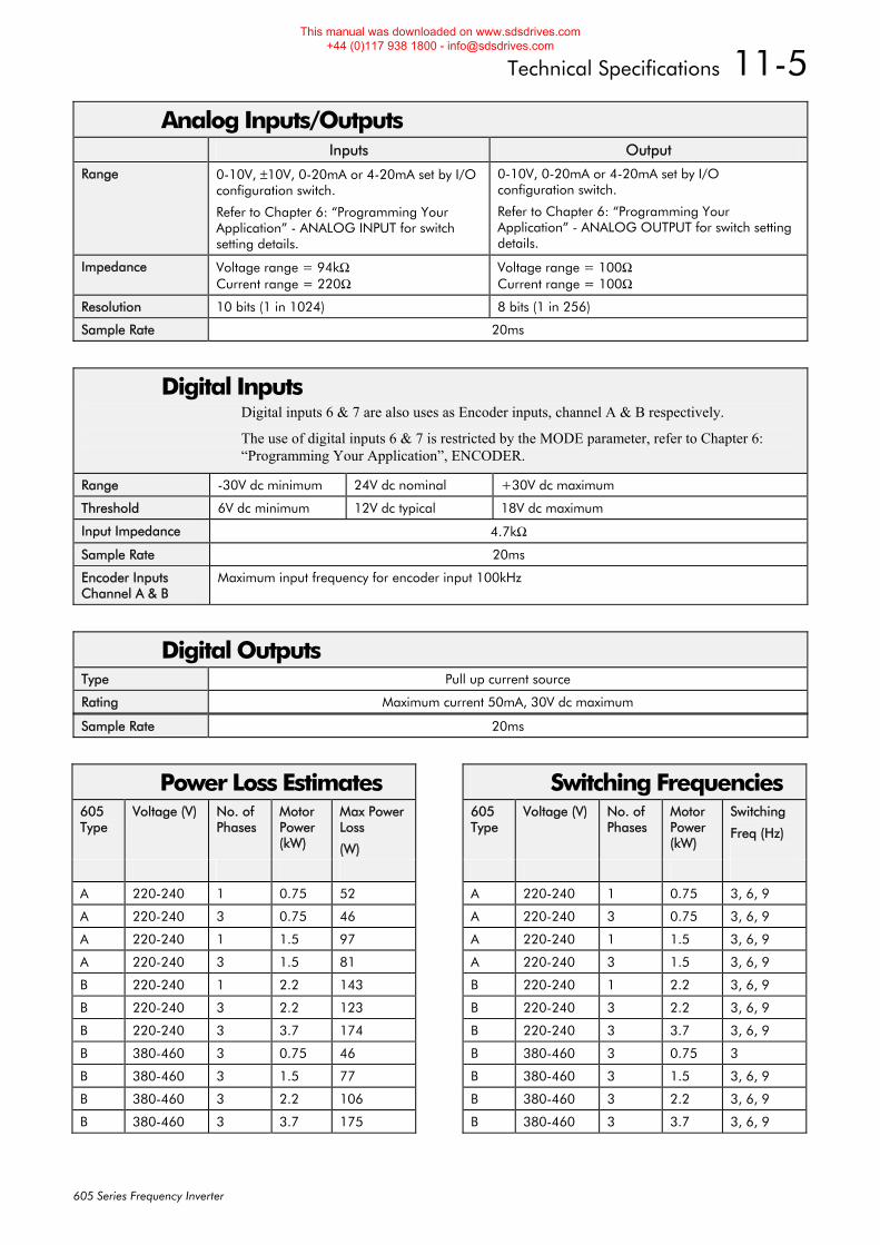
Technical Specifications 11-5
605 Series Frequency Inverter
Analog Inputs/Outputs Inputs Output
Range 0-10V, ±10V, 0-20mA or 4-20mA set by I/O configuration switch.
Refer to Chapter 6: “Programming Your Application” - ANALOG INPUT for switch setting details.
0-10V, 0-20mA or 4-20mA set by I/O configuration switch.
Refer to Chapter 6: “Programming Your Application” - ANALOG OUTPUT for switch setting details.
Impedance Voltage range = 94kΩ Current range = 220Ω
Voltage range = 100Ω Current range = 100Ω
Resolution 10 bits (1 in 1024) 8 bits (1 in 256)
Sample Rate 20ms
Digital Inputs Digital inputs 6 & 7 are also uses as Encoder inputs, channel A & B respectively.
The use of digital inputs 6 & 7 is restricted by the MODE parameter, refer to Chapter 6: “Programming Your Application”, ENCODER.
Range -30V dc minimum 24V dc nominal +30V dc maximum
Threshold 6V dc minimum 12V dc typical 18V dc maximum
Input Impedance 4.7kΩ
Sample Rate 20ms
Encoder Inputs Channel A & B
Maximum input frequency for encoder input 100kHz
Digital Outputs Type Pull up current source
Rating Maximum current 50mA, 30V dc maximum
Sample Rate 20ms
Power Loss Estimates 605 Type
Voltage (V) No. of Phases
Motor Power (kW)
Max Power Loss
(W)
A 220-240 1 0.75 52
A 220-240 3 0.75 46
A 220-240 1 1.5 97
A 220-240 3 1.5 81
B 220-240 1 2.2 143
B 220-240 3 2.2 123
B 220-240 3 3.7 174
B 380-460 3 0.75 46
B 380-460 3 1.5 77
B 380-460 3 2.2 106
B 380-460 3 3.7 175
Switching Frequencies 605 Type
Voltage (V) No. of Phases
Motor Power (kW)
Switching
Freq (Hz)
A 220-240 1 0.75 3, 6, 9
A 220-240 3 0.75 3, 6, 9
A 220-240 1 1.5 3, 6, 9
A 220-240 3 1.5 3, 6, 9
B 220-240 1 2.2 3, 6, 9
B 220-240 3 2.2 3, 6, 9
B 220-240 3 3.7 3, 6, 9
B 380-460 3 0.75 3
B 380-460 3 1.5 3, 6, 9
B 380-460 3 2.2 3, 6, 9
B 380-460 3 3.7 3, 6, 9
This manual was downloaded on www.sdsdrives.com +44 (0)117 938 1800 - [email protected]
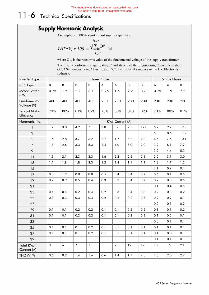
11-6 Technical Specifications
605 Series Frequency Inverter
Supply Harmonic Analysis Assumptions: 5000A short circuit supply capability:
THD(V) x 100 = =∑ QQ
h2
1nh 40
=h 2
%
where Q1n is the rated rms value of the fundamental voltage of the supply transformer. The results conform to stage 1, stage 2 and stage 3 of the Engineering Recommendation G.5/3 September 1976, Classification ‘C’: Limits for Harmonics in the UK Electricity Industry.
Inverter Type Three Phase Single Phase
605 Type B B B B A A B B A A B
Motor Power (kW)
0.75 1.5 2.2 3.7 0.75 1.5 2.2 3.7 0.75 1.5 2.2
Fundamental Voltage (V)
400 400 400 400 230 230 230 230 230 230 230
Typical Motor Efficiency
73% 80% 81% 82% 73% 80% 81% 82% 73% 80% 81%
Harmonic No. RMS Current (A)
1 1.7 3.0 4.2 7.1 3.0 5.6 7.5 12.0 5.2 9.2 12.9
3 5.0 8.6 11.9
5 1.6 2.8 3.7 6.2 2.7 4.7 6.2 9.3 4.5 7.5 10.1
7 1.5 2.6 3.3 5.3 2.4 4.0 5.0 7.0 3.9 6.1 7.7
9 3.2 4.6 5.3
11 1.3 2.1 2.3 3.3 1.6 2.2 2.5 2.6 2.5 3.1 3.0
13 1.1 1.8 1.8 2.3 1.2 1.4 1.4 1.1 1.8 1.7 1.2
15 1.1 0.7 0.1
17 0.8 1.2 0.8 0.8 0.5 0.4 0.4 0.7 0.6 0.1 0.5
19 0.7 0.9 0.5 0.4 0.3 0.3 0.4 0.7 0.2 0.3 0.6
21 0.1 0.4 0.5
23 0.4 0.4 0.2 0.4 0.2 0.3 0.4 0.3 0.2 0.3 0.2
25 0.3 0.3 0.3 0.4 0.2 0.2 0.2 0.3 0.2 0.2 0.1
27 0.2 0.1 0.2
29 0.1 0.1 0.2 0.2 0.1 0.1 0.2 0.2 0.1 0.1 0.2
31 0.1 0.1 0.2 0.2 0.1 0.1 0.2 0.2 0.1 0.2 0.1
33 0.0 0.1 0.1
35 0.1 0.1 0.1 0.2 0.1 0.1 0.1 0.1 0.1 0.1 0.1
37 0.1 0.1 0.1 0.2 0.1 0.1 0.1 0.1 0.1 0.0 0.1
39 0.1 0.1 0.1
Total RMS Current (A)
3 6 7 11 5 9 12 17 10 16 23
THD (V) % 0.6 0.9 1.4 1.6 0.6 1.4 1.7 2.5 1.5 2.0 2.7
This manual was downloaded on www.sdsdrives.com +44 (0)117 938 1800 - [email protected]
Certification for the Inverter 12-1
605 Series Frequency Inverter
12CERTIFICATION FOR THE INVERTER Requirements for EMC Compliance
All Variable Speed Drives (VSDs) potentially produce electrical emissions which are radiated into the environment and conducted back into the ac supply. VSDs are inherently immune to any additional external electrical noise. The following information is provided to maximise the Electro Magnetic Compatibility (EMC) of VSDs and systems in their intended operating environment, by minimising their emissions and maximising their immunity.
Minimising Radiated Emissions EN55011 radiated emission measurements are made between 30MHz and 1GHz in the far field at a distance of 10 to 30 metres. Limits lower than 30MHz or in close proximity are not specified. Emissions from individual components tend to be additive.
• Use a screened/armoured cable between VSD/cubicle and motor containing the motor protective earth (PE) connection. It should have a 360° screen termination. Earth screen at both ends connecting to the motor frame and cubicle (or gland box if wall mounted). Maintain the screen integrity using 360° terminations.
Note: Some hazardous area installations may preclude direct earthing at both ends of the screen, in this case earth one end via a 1μF 50Vac capacitor, and the other as normal.
• Keep unshielded cable as short as possible inside the cubicle.
• Always maintain the integrity of the shield.
• If the cable is interrupted to insert contactors etc., re-connect the screen using the shortest possible route.
• Keep the length of screen stripped-back as short as possible when making screen connections.
• Ideally use 360° screen terminations using cable glands or `U’ clips on power sceen rails.
If a shielded cable is not available, lay unshielded motor cables in a metal conduit which will act as a shield. The conduit must be continuous with a direct electrical contact to the VSD and motor housing. If links are necessary, use braid with a minimum cross sectional area of 10mm2.
Note: Some motor gland boxes and conduit glands are made of plastic, if this is the case, then braid must be connected between the screen and the chassis. In addition at the motor end, ensure that the screen is electrically connected to the motor frame since some terminal boxes are insulated from the frame by gasket/paint.
Earthing Requirements IMPORTANT: Protective earthing always takes precedence over EMC earthing.
Protective Earth (PE) Connections Note: In accordance with the installation requirements of EN60204, only one protective earth
conductor is permitted at each protective earth terminal contacting point.
Local wiring regulations may require the protective earth connection of the motor to be connected locally, i.e. not as specified in these instructions. This will not cause shielding problems because of the relatively high RF impedance of the local earth connection.
EMC Earth Connections For compliance with EMC requirements, we recommend that the “0V/signal ground” is separately earthed. When a number of units are used in a system, these terminals should be connected together at a single, local earthing point.
This manual was downloaded on www.sdsdrives.com +44 (0)117 938 1800 - [email protected]
12-2 Certification for the Inverter
605 Series Frequency Inverter
Control and signal cables for the encoder, all analog inputs, and communications require screening with the screen connected only at the VSD end. However, if high frequency noise is still a problem, earth screen at the non VSD end via a 0.1μF capacitor.
Note: Connect the screen (at the VSD end) to the VSD protective point, and not to the control board terminals.
Cabling Requirements Note: Refer to Chapter 11: “Technical Specifications” for additional Cabling Requirements.
Planning Cable Runs • Use the shortest possible motor cable lengths.
• Use a single length of cable to a star junction point to feed multiple motors.
• Keep electrically noisy and sensitive cables apart.
• Keep electrically noisy and sensitive parallel cable runs to a minimum. Separate parallel cable runs by at least 0.25 metres. For runs longer than 10 metres, separation should be increased proportionally. For example if the parallel runs were 50m, then the separation would be (50/10) x 0.25m = 1.25m.
• Sensitive cables should cross noisy cables at 90°.
• Never run sensitive cables close or parallel to the motor, dc link and braking chopper circuit for any distance.
• Never run supply, dc link or motor cables in the same bundle as the signal/control and feedback cables, even if they are screened.
• Ensure EMC filter input and output cables are separately routed and do not couple across the filter.
Increasing Motor Cable Length Because cable capacitance and hence conducted emissions increase with motor cable length, conformance to EMC limits is only guaranteed with the specified internal ac supply EMC filter option using a maximum cable length as specified in Chapter 11: “Technical Specifications”.
This maximum cable length can be improved using the specified external ac EMC output filter. Refer to Chapter 11: “Technical Specifications” - External AC Supply EMC Filters. Note that the external filter cannot be used with an internal filter.
Screened/armoured cable has significant capacitance between the conductors and screen which increases linearly with cable length (typically 200pF/m but varies with cable type and current rating).
Long cable lengths may have the following undesirable effects:
• Tripping on `overcurrent’ as the cable capacitance is charged and discharged at the switching frequency.
• Producing increased conducted emissions which degrade the performance of the internal/external ac supply EMC filter due to saturation.
• Causing RCDs (Residual Current Devices) to trip due to increased high frequency earth current.
• Producing increased heating inside the internal/external ac supply EMC filter from the increased conducted emissions.
These effects can be overcome by adding motor chokes or an EMC motor output filter at the output of the VSD.
This manual was downloaded on www.sdsdrives.com +44 (0)117 938 1800 - [email protected]
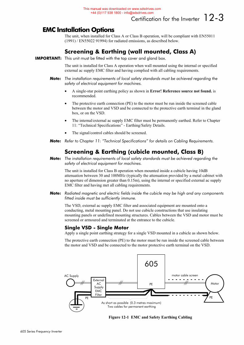
Certification for the Inverter 12-3
605 Series Frequency Inverter
EMC Installation Options The unit, when installed for Class A or Class B operation, will be compliant with EN55011 (1991) / EN55022 91994) for radiated emissions, as described below.
Screening & Earthing (wall mounted, Class A) IMPORTANT: This unit must be fitted with the top cover and gland box.
The unit is installed for Class A operation when wall mounted using the internal or specified external ac supply EMC filter and having complied with all cabling requirements.
Note: The installation requirements of local safety standards must be achieved regarding the safety of electrical equipment for machines.
• A single-star point earthing policy as shown in Error! Reference source not found. is recommended.
• The protective earth connection (PE) to the motor must be run inside the screened cable between the motor and VSD and be connected to the protective earth terminal in the gland box, or on the VSD.
• The internal/external ac supply EMC filter must be permanently earthed. Refer to Chapter 11: “Technical Specifications” - Earthing/Safety Details.
• The signal/control cables should be screened.
Note: Refer to Chapter 11: “Technical Specifications” for details on Cabling Requirements.
Screening & Earthing (cubicle mounted, Class B) Note: The installation requirements of local safety standards must be achieved regarding the
safety of electrical equipment for machines.
The unit is installed for Class B operation when mounted inside a cubicle having 10dB attenuation between 30 and 100MHz (typically the attenuation provided by a metal cabinet with no aperture of dimension greater than 0.15m), using the internal or specified external ac supply EMC filter and having met all cabling requirements.
Note: Radiated magnetic and electric fields inside the cubicle may be high and any components fitted inside must be sufficiently immune.
The VSD, external ac supply EMC filter and associated equipment are mounted onto a conducting, metal mounting panel. Do not use cubicle constructions that use insulating mounting panels or undefined mounting structures. Cables between the VSD and motor must be screened or armoured and terminated at the entrance to the cubicle.
Single VSD - Single Motor Apply a single point earthing strategy for a single VSD mounted in a cubicle as shown below.
The protective earth connection (PE) to the motor must be run inside the screened cable between the motor and VSD and be connected to the motor protective earth terminal on the VSD.
AC Supply
Motor
motor cable screen
PE
As short as possible
PE
(0.3 metres maximum)
605
PEAC
Filter
Two cables for permanent earthing
SupplyEMC
External
Figure 12-1 EMC and Safety Earthing Cabling
This manual was downloaded on www.sdsdrives.com +44 (0)117 938 1800 - [email protected]
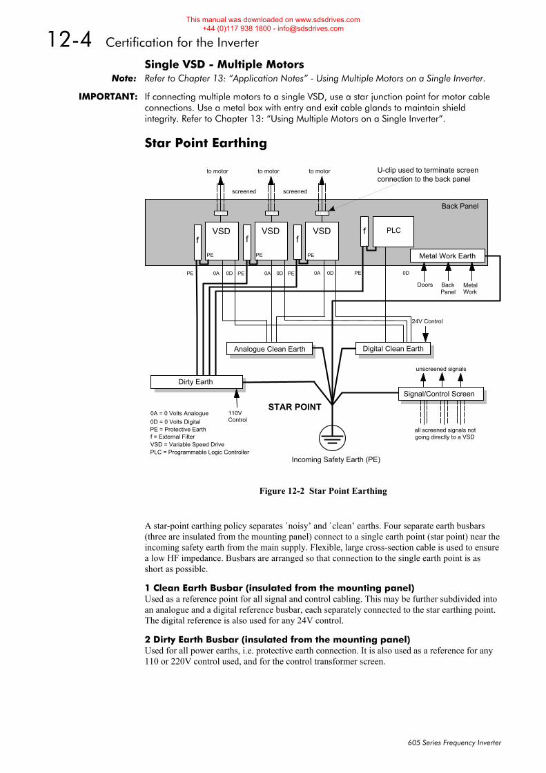
12-4 Certification for the Inverter
605 Series Frequency Inverter
Single VSD - Multiple Motors Note: Refer to Chapter 13: “Application Notes” - Using Multiple Motors on a Single Inverter.
IMPORTANT: If connecting multiple motors to a single VSD, use a star junction point for motor cable connections. Use a metal box with entry and exit cable glands to maintain shield integrity. Refer to Chapter 13: “Using Multiple Motors on a Single Inverter”.
Star Point Earthing
A star-point earthing policy separates `noisy’ and `clean’ earths. Four separate earth busbars (three are insulated from the mounting panel) connect to a single earth point (star point) near the incoming safety earth from the main supply. Flexible, large cross-section cable is used to ensure a low HF impedance. Busbars are arranged so that connection to the single earth point is as short as possible.
1 Clean Earth Busbar (insulated from the mounting panel) Used as a reference point for all signal and control cabling. This may be further subdivided into an analogue and a digital reference busbar, each separately connected to the star earthing point. The digital reference is also used for any 24V control.
2 Dirty Earth Busbar (insulated from the mounting panel) Used for all power earths, i.e. protective earth connection. It is also used as a reference for any 110 or 220V control used, and for the control transformer screen.
Doors Metal Work
110VControl
24V Control
unscreened signals
STAR POINT
Incoming Safety Earth (PE)
Analogue Clean Earth
Dirty Earth
Digital Clean Earth
Signal/Control Screen
all screened signals not
Back Panel
U-clip used to terminate screenconnection to the back panel
PE = Protective Earth
0A = 0 Volts Analogue0D = 0 Volts Digital
f = External FilterVSD = Variable Speed DrivePLC = Programmable Logic Controller
going directly to a VSD
Metal Work Earth
BackPanel
PLC
PE PE PE0D 0D 0D 0D0A 0A 0A
to motor to motor to motor
screened screened
PE
VSD VSDVSDf f f
f
PEPEPE
Figure 12-2 Star Point Earthing
This manual was downloaded on www.sdsdrives.com +44 (0)117 938 1800 - [email protected]
Certification for the Inverter 12-5
605 Series Frequency Inverter
3 Metal Work Earth Busbar The back panel is used as this earth busbar, and should provide earthing points for all parts of the cubicle including panels and doors. This busbar is also used for power screened cables which terminate near to (10cm) or directly into a VSD - such as motor cables, braking choppers and their resistors, or between VSDs - refer to the appropriate product manual to identify these. Use U-clips to clamp the screened cables to the back panel to ensure optimim HF connection.
4 Signal/Control Screen Earth Busbar (insulated from the mounting panel) Used for signal/control screened cables which do not go directly to the VSD. Place this busbar as close as possible to the point of cable entry. `U’ clamp the screened cables to the busbars to ensure an optimum HF connection.
Sensitive Equipment The proximity of the source and victim circuit has a large effect on radiated coupling. The electromagnetic fields produced by VSDs falls off rapidly with distance from the cabling/cubicle. Remember that the radiated fields from EMC compliant drive systems are measured at least 10m from the equipment, over the band 30-1000MHz. Any equipment placed closer than this will see larger magnitude fields, especially when very close to the Inverter.
Do not place magnetic/electric field sensitive equipment within 0.25 metres of the following parts of the VSD system:
• Variable Speed Drive (VSD)
• EMC motor output filters
• Input or output chokes/transformers
• The cable between VSD and motor (even when screened/armoured)
• Connections to external braking chopper and resistor (even when screened/armoured)
• AC/DC brushed motors (due to commutation)
• DC link connections (even when screened/armoured)
• Relays and contactors (even when suppressed)
From experience, the following equipment is particularly sensitive and requires careful installation.
• Any transducers which produce low level analog outputs (<1V) , e.g. load cells, strain gauges, thermocouples, piezoelectric transducers, anemometers, LVDTs
• Wide band width control inputs (>100Hz)
• AM radios (long and medium wave only)
• Video cameras and closed circuit TV
• Office personal computers
• Capacitive devices such as proximity sensors and level transducers
• Mains borne communication systems
• Equipment not suitable for operation in the intended EMC environment, i.e. with insufficient immunity to new EMC standards
This manual was downloaded on www.sdsdrives.com +44 (0)117 938 1800 - [email protected]
12-6 Certification for the Inverter
605 Series Frequency Inverter
Requirements for UL Compliance Solid-State Motor Overload Protection These devices provide Class 10 motor overload protection. The maximum internal overload protection level (current limit) is 150% for 60 seconds. Refer to Chapter 6: Programming Your Application - I*t TRIP for user current limit adjustment information.
An external motor overload protective device must be provided by the installer where the motor has a full-load ampere rating of less than 50% of the Inverter output rating.
Short Circuit Rating All models of this Inverter are suitable for use on a circuit capable of delivering not more than 5000 RMS Symmetrical Amperes, 240V/460V maximum (as appropriate).
Solid-State Short-Circuit Protection These devices are provided with Solid-State Short-Circuit (output) Protection. Branch circuit fusing requirements must be in accordance with the latest edition of the National Electrical Code NEC/NFPA-70.
Recommended Branch Circuit Protection It is recommended that UL Listed (JDDZ) non-renewable cartridge fuses, Class K5 or H; or UL Listed (JDRX) renewable cartridge fuses, Class H, are installed upstream of the Inverter. Refer to Chapter 11: “Technical Specifications” - Power Details for recommended fuse ratings.
Motor Base Frequency The motor base frequency rating is 480Hz maximum.
Field Wiring Temperature Rating Use 60°C or 60/75°C Copper conductors only.
Field Wiring Terminal Markings For correct field wiring connections that are to be made to each terminal refer to Error! Reference source not found. page 3-Error! Bookmark not defined., and Error! Reference source not found. page 3-Error! Bookmark not defined..
Power Wiring Terminals The wiring terminals accept a maximum conductor size of No. 10 AWG (5.3mm²).
Terminal Tightening Torque The tightening torque for the power terminals is 9 lbf-in (1.0Nm).
Field Grounding Terminals The field grounding terminals are identified with the International Grounding Symbol (IEC Publication 417, Symbol 5019).
Operating Ambient Temperature The maximum operating ambient temperature rating is 45°C (40°C for models with a Type 1 Enclosure).
Direct Wall-Mountable Models All model of this Inverter with a Product Code Block VI designation xx20 and xx21 are suitable for direct wall mounting applications as they have a “Type 1 Enclosure” rating.
In order to preserve this enclosure rating, it is important to maintain the environmental integrity of the enclosure. Therefore, the installer must provide correct Type 1 closures for all unused clearance holes provided within the Inverter’s glandplate.
Type 1 Enclosed models are suitable for use in no worse than a Pollution Degree 2 environment.
This manual was downloaded on www.sdsdrives.com +44 (0)117 938 1800 - [email protected]
Certification for the Inverter 12-7
605 Series Frequency Inverter
European Directives and the CE Mark The following information is supplied to provide a basic understanding of the Electro Magnetic Compatibility (EMC) and Low Voltage Directive (LVD) CE marking requirements. The following literature is recommended for further information:
• Recommendations for Application of Power Drive Systems (PDS), European Council Directives - CE Marking and Technical Standardisation - (CEMEP)
Available from your local trade association.
• EMC Installation Guidelines for Modules and Systems - (Parker SSD Drives)
Available from your local Parker SSD Drives office, part number HA388879
• Short Form Overview of European Directives for Variable Speed Drives and Applications - (Parker SSD Drives)
Available from your local Parker SSD Drives office, part number HA389770
The European machines and drives manufacturers via their national trade associations have formed the European Committee of Manufacturers of Electrical Machines and Power Electronics (CEMEP).
Parker SSD Drives and other major European drives manufacturers are working to the CEMEP recommendations on CE marking.
The CE mark shows that a product complies with the relevant EU directives, in our case the LVD and, in some instances, the EMC Directive.
CE Marking for Low Voltage Directive When installed in accordance with this manual, the Inverter is CE marked by Parker SSD Drives Ltd in accordance with the low voltage directive (S.I. No. 3260 implements this LVD directive into UK law). An EC Declaration of Conformity (low voltage directive) is included at the end of this chapter.
CE Marking for EMC - Who is Responsible? Note: The specified EMC emission and immunity performance of this unit can only be achieved
when the unit is installed to the EMC Installation Instructions given in this manual.
According to S.I. No. 2373 which implements the EMC directive into UK law, the requirement for CE marking this unit falls into two categories:
1. Where the supplied unit has an intrinsic/direct function to the end user, then the unit is classed as Relevant Apparatus.
2. Where the supplied unit is incorporated into a higher system/apparatus or machine which includes (at least) the motor, cable and a driven load but is unable to function without this unit, then the unit is classed as a Component.
Relevant Apparatus - Parker SSD Drives Responsibility Occasionally, say in a case where an existing fixed speed motor - such as a fan or pump - is converted to variable speed with an add-on drive module (Relevant Apparatus), it becomes the responsibility of Parker SSD Drives to apply the CE mark and issue an EC Declaration of Conformity for the EMC Directive. This declaration and the CE mark is included at the end of this chapter.
Component - Customer Responsibility The majority of Parker SSD Drives’ products are classed as Components and therefore we cannot apply the CE mark or produce an EC Declaration of Conformity in respect of EMC. It is therefore the manufacturer/supplier/installer of the higher system/apparatus or machine who must conform to the EMC directive and CE mark.
This manual was downloaded on www.sdsdrives.com +44 (0)117 938 1800 - [email protected]
12-8 Certification for the Inverter
605 Series Frequency Inverter
The Legal Requirements of CE Marking for EMC IMPORTANT: Before installation, clearly understand who is responsible for conformance with the EMC
Directive. Misappropriation of the CE mark is a CRIMINAL OFFENCE.
It is important that you have now defined who is responsible for conforming to the EMC Directive, either:
Parker SSD Drives Responsibility You intend to use the unit as Relevant Apparatus.
When the unit has an internal ac supply EMC filter, or the specified external ac supply EMC filter is correctly fitted to the unit, and the EMC installation instructions have been followed it complies with the relevant standards indicated in the following tables. The use of a filter is mandatory for the CE marking of this unit to apply.
The relevant declarations are to be found at the end of this chapter. The CE mark is displayed on the EC Declaration of Conformity (EMC Directive) provided at the end of this chapter.
Customer Responsibility You intend to use the unit as a Component, therefore you have a choice:
1. To use the internal or specified external ac supply EMC filter, following the EMC installation instructions. This may help you gain EMC compliance for the final machine/system.
2. Where the unit does not have an internal ac supply EMC filter, you can use a combination of global or local filtering and screening methods, natural migration through distance, or the use of distributed parasitic elements of the existing installation.
Note: When two or more EMC compliant components are combined to form the final machine/system, the resulting machine/system may no longer be compliant, (emissions tend to be additive, immunity is determined by the least immune component).
Understand the EMC environment and applicable standards to keep additional compliance costs to a minimum.
Applying for CE Marking for EMC We have supplied a Manufacturer’s EMC Declaration at the end of this chapter that you can use as a basis for your own justification of overall compliance with the EMC directive. There are three methods of demonstrating conformity:
1. Self-certification to a relevant standard
2. Third party testing to a relevant standard
3. Writing a technical construction file stating the technical rationale as to why your final machine/system is compliant. An EMC “competent body” must then assess this and issue a technical report or certificate to demonstrate compliance. Refer to Article 10(2) of Directive 89/336/EEC.
With EMC compliance, an EC Declaration of Conformity and the CE mark will be issued for your final machine/system.
IMPORTANT: Professional end users with EMC expertise who are using drive modules and cubicle systems defined as components who supply, place on the market or install the relevant apparatus must take responsibility for demonstrating EMC conformance and applying the CE mark and issuing an EC Declaration of Conformity.
This manual was downloaded on www.sdsdrives.com +44 (0)117 938 1800 - [email protected]
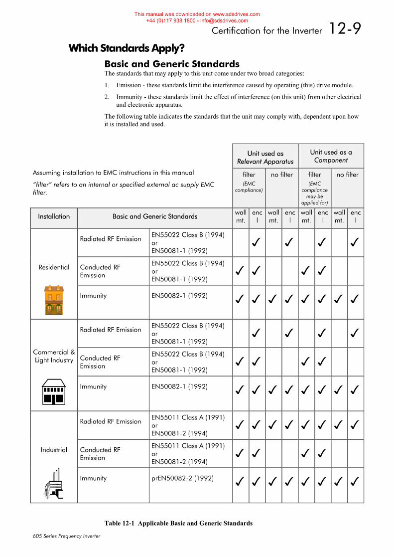
Certification for the Inverter 12-9
605 Series Frequency Inverter
Which Standards Apply? Basic and Generic Standards The standards that may apply to this unit come under two broad categories:
1. Emission - these standards limit the interference caused by operating (this) drive module.
2. Immunity - these standards limit the effect of interference (on this unit) from other electrical and electronic apparatus.
The following table indicates the standards that the unit may comply with, dependent upon how it is installed and used.
Unit used as Relevant Apparatus
Unit used as a Component
Assuming installation to EMC instructions in this manual
“filter” refers to an internal or specified external ac supply EMC filter.
filter (EMC
compliance)
no filter filter (EMC
compliance may be
applied for)
no filter
Installation Basic and Generic Standards wallmt.
encl
wall mt.
encl
wall mt.
encl
wallmt.
encl
Radiated RF Emission EN55022 Class B (1994)
or EN50081-1 (1992)
Residential Conducted RF Emission
EN55022 Class B (1994) or EN50081-1 (1992)
Immunity EN50082-1 (1992)
Radiated RF Emission EN55022 Class B (1994)
or EN50081-1 (1992)
Commercial & Light Industry Conducted RF
Emission
EN55022 Class B (1994) or EN50081-1 (1992)
Immunity EN50082-1 (1992)
Radiated RF Emission EN55011 Class A (1991)
or EN50081-2 (1994)
Industrial Conducted RF Emission
EN55011 Class A (1991) or EN50081-2 (1994)
Immunity prEN50082-2 (1992)
Table 12-1 Applicable Basic and Generic Standards
This manual was downloaded on www.sdsdrives.com +44 (0)117 938 1800 - [email protected]
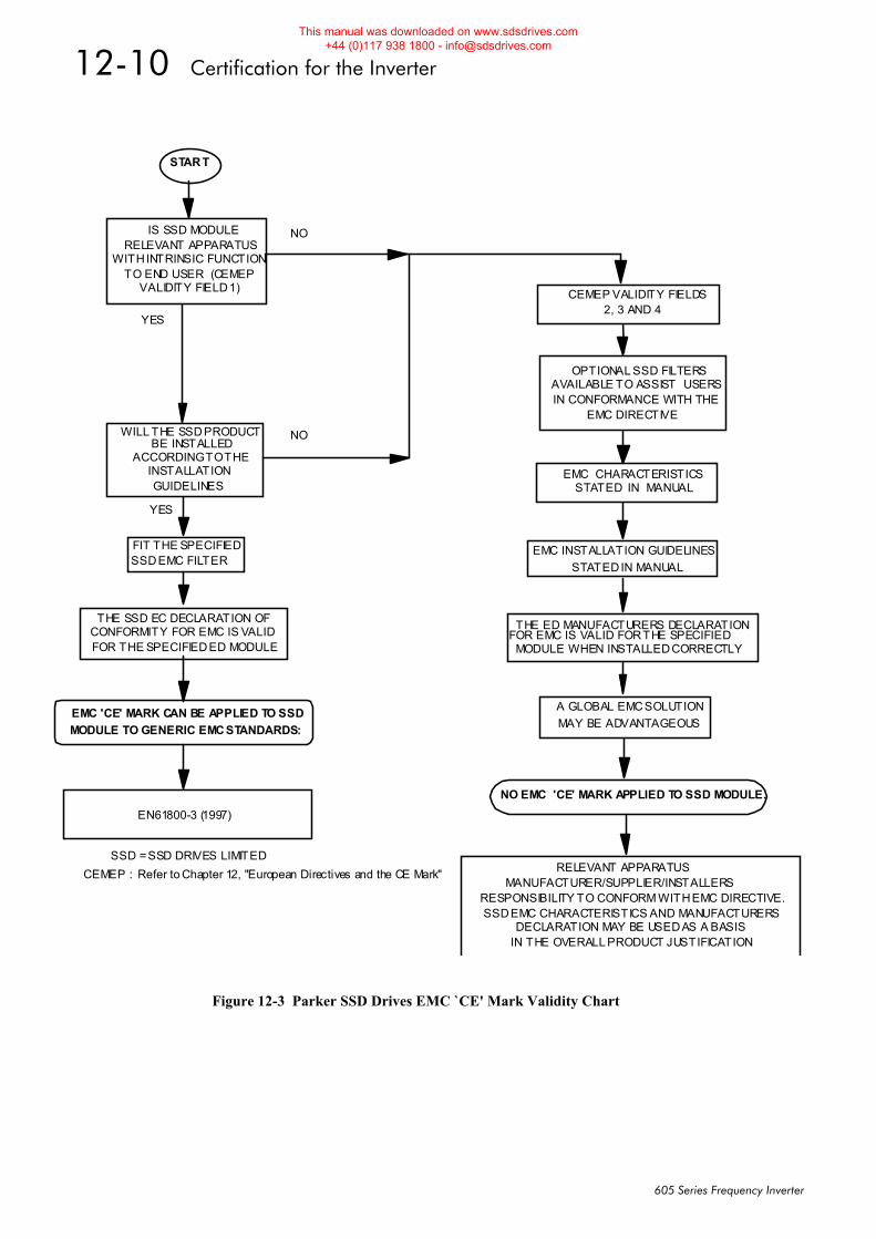
12-10 Certification for the Inverter
605 Series Frequency Inverter
THE SSD EC DECLARATION OF CONFORMITY FOR EMC IS VALID FOR THE SPECIFIED ED MODULE
START
IS SSD MODULE RELEVANT APPARATUS
WITH INTRINSIC FUNCTION TO END USER (CEMEP
VALIDITY FIELD 1)
NO
YES
FIT THE SPECIFIED SSD EMC FILTER
WILL THE SSD PRODUCT BE INSTALLED
ACCORDING TO THE INSTALLATION GUIDELINES
NO
YES
SSD = SSD DRIVES LIMITED
EMC 'CE' MARK CAN BE APPLIED TO SSD MODULE TO GENERIC EMC STANDARDS:
EN61800-3 (1997)
EMC CHARACTERISTICS
STATED IN MANUAL
OPTIONAL SSD FILTERS AVAILABLE TO ASSIST USERS IN CONFORMANCE WITH THE
EMC DIRECTIVE
EMC INSTALLATION GUIDELINES STATED IN MANUAL
CEMEP VALIDITY FIELDS 2, 3 AND 4
NO EMC 'CE' MARK APPLIED TO SSD MODULE.
A GLOBAL EMC SOLUTION MAY BE ADVANTAGEOUS
MANUFACTURER/SUPPLIER/INSTALLERS RESPONSIBILITY TO CONFORM WITH EMC DIRECTIVE. SSD EMC CHARACTERISTICS AND MANUFACTURERS
IN THE OVERALL PRODUCT JUSTIFICATION
RELEVANT APPARATUS
THE ED MANUFACTURERS DECLARATION FOR EMC IS VALID FOR THE SPECIFIED
MODULE WHEN INSTALLED CORRECTLY
DECLARATION MAY BE USED AS A BASIS
CEMEP : Refer to Chapter 12, "European Directives and the CE Mark"
Figure 12-3 Parker SSD Drives EMC `CE' Mark Validity Chart
This manual was downloaded on www.sdsdrives.com +44 (0)117 938 1800 - [email protected]
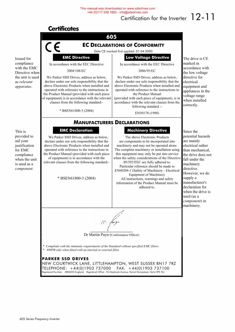
Certification for the Inverter 12-11
605 Series Frequency Inverter
Certificates 605
EC DECLARATIONS OF CONFORMITY Date CE marked first applied: 01.04.2000
Issued for EMC Directive Low Voltage Directive The drive is CE compliance with the EMC Directive when the unit is used as relevant apparatus.
In accordance with the EEC Directive
2004/108/EC
We Parker SSD Drives, address as below, declare under our sole responsibility that the above Electronic Products when installed and operated with reference to the instructions in
the Product Manual (provided with each piece of equipment) is in accordance with the relevant
clauses from the following standard:-
* BSEN61800-3 (2004)
In accordance with the EEC Directive
2006/95/EC
We Parker SSD Drives, address as below, declare under our sole responsibility that the above Electronic Products when installed and operated with reference to the instructions in
the Product Manual (provided with each piece of equipment), is in accordance with the relevant clauses from the
following standard :-
EN50178 (1998)
marked in accordance with the low voltage directive for electrical equipment and appliances in the voltage range when installed correctly.
MANUFACTURERS DECLARATIONS
This is EMC Declaration Machinery Directive Since the provided to aid your justification for EMC compliance when the unit is used as a component.
We Parker SSD Drives, address as below, declare under our sole responsibility that the above Electronic Products when installed and operated with reference to the instructions in
the Product Manual (provided with each piece of equipment) is in accordance with the
relevant clauses from the following standard:-
* BSEN61800-3 (2004)
The above Electronic Products are components to be incorporated into
machinery and may not be operated alone. The complete machinery or installation using this equipment may only be put into service
when the safety considerations of the Directive 89/392/EEC are fully adhered to.
Particular reference should be made to EN60204-1 (Safety of Machinery - Electrical
Equipment of Machines). All instructions, warnings and safety
information of the Product Manual must be adhered to.
potential hazards are mainly electrical rather than mechanical, the drive does not fall under the machinery directive. However, we do supply a manufacturer's declaration for when the drive is used (as a component) in machinery.
Dr Martin Payn (Conformance Officer)
* Compliant with the immunity requirements of the Standard without specified EMC filters. * 690PB only when fitted with an internal or external filter. PARKER SSD DRIVES NEW COURTWICK LANE, LITTLEHAMPTON, WEST SUSSEX BN17 7RZ TELEPHONE: +44(0)1903 737000 FAX: +44(0)1903 737100 Registered Number: 4806503 England. Registered Office: 55 Maylands Avenue, Hemel Hempstead, Herts HP2 4SJ
This manual was downloaded on www.sdsdrives.com +44 (0)117 938 1800 - [email protected]

12-12 Certification for the Inverter
605 Series Frequency Inverter
This manual was downloaded on www.sdsdrives.com +44 (0)117 938 1800 - [email protected]
Application Notes 13-1
605 Series Frequency Inverter
13APPLICATION NOTES Application advice is available through our Technical Support Department, who can also arrange for on-site assistance if required. Refer to Chapter 8: “Routine Maintenance and Repair” for the address of your local Eurothem Drives company.
• Always use gold flash relays, or others designed for low current operation (5mA), on all control wiring.
• Remove all power factor correction equipment from the motor side of the Inverter before use.
• Avoid using motors with low efficiency and small cos ø (power factor) as they require a larger kVA rated Inverter to produce the correct shaft kW.
Synchronous Motor Control Although intended primarily for use with induction (asynchronous) motors, Inverters can also be used for speed control of synchronous motors. Synchronous motors can offer economic solutions in applications where tight control of speed is required together with the low maintenance characteristics of an ac motor.
The two most common types of synchronous ac motor are permanent magnet and wound rotor.
In contrast to induction motors, synchronous motors run at synchronous speed whether on full load or no load. Synchronous speed is set by the frequency of the supply applied to the stator. The stator flux can be kept constant by keeping the stator volts/frequency ratio constant, as with an induction motor.
Torque is produced in the motor by an increase in load angle between the stator and rotor fluxes. Maximum torque occurs when the load angle approaches 90°. If the load angle exceeds this value then torque drops and the motor will stall. Systems involving synchronous motors need careful design to ensure that the motor can accelerate the load and handle transient load changes without stalling.
Brake Motors Brake motors are used in applications requiring a mechanical brake for safety or other operational reasons. The motor can be a standard induction motor fitted with an electro-mechanical brake, or it could be a special conical rotor machine. In the case of a conical rotor machine the spring-loaded brake is controlled by the motor terminal voltage as follows:
• At rest the motor is braked.
• When the motor is energised an axial component of the magnetic field due to the conical air-gap overcomes the force of the brake spring and draws the rotor into the stator. This axial displacement releases the brake and allows the motor to accelerate like a normal induction motor.
• When the motor is de-energised the magnetic field collapses and the brake spring displaces the rotor, pushing the brake disc against the braking surface.
Inverters can be used to control the speed of conical rotor brake motors since the linear V/F characteristic maintains the motor magnetic field constant over the speed range. It will be necessary to set the FIXED BOOST parameter to overcome motor losses at low speed (see FLUXING menu at level 3).
This manual was downloaded on www.sdsdrives.com +44 (0)117 938 1800 - [email protected]
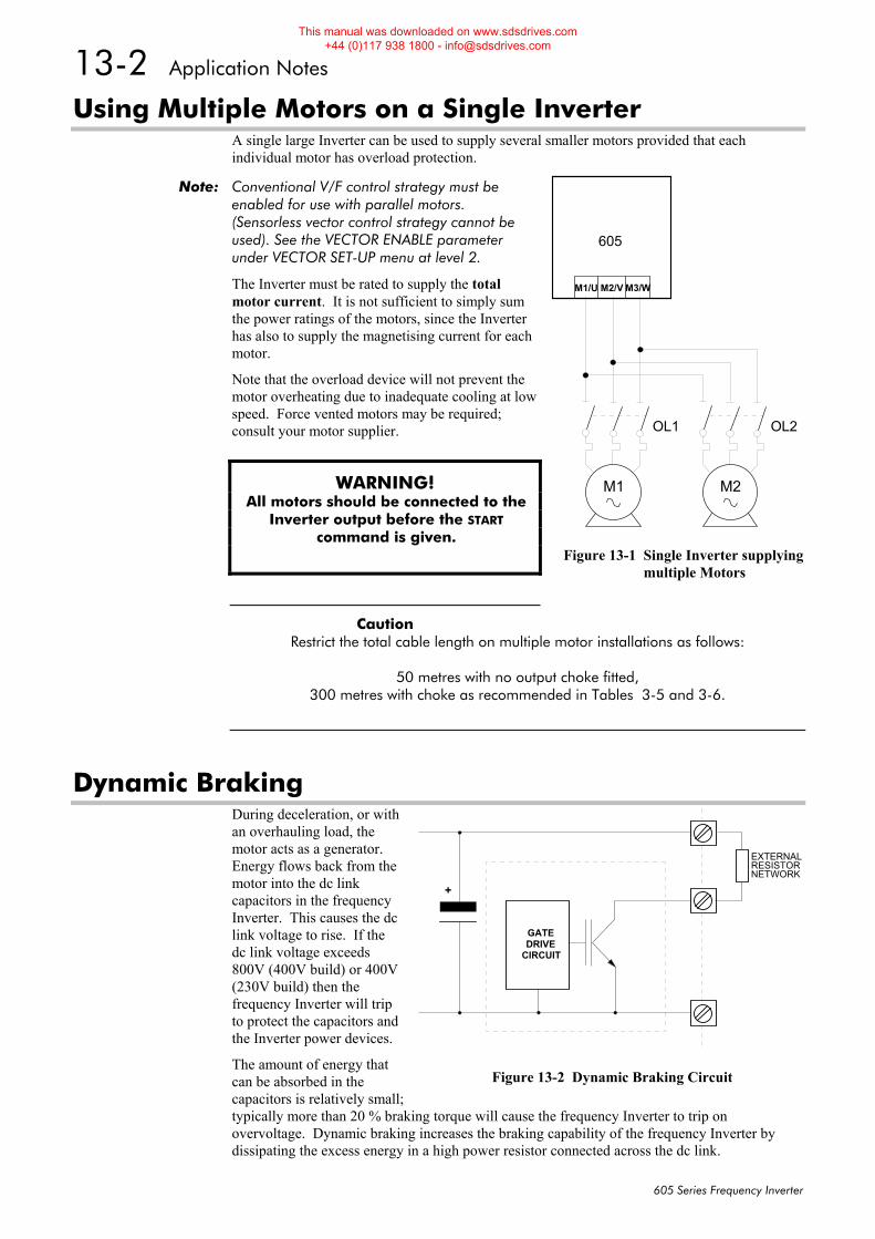
13-2 Application Notes
605 Series Frequency Inverter
Using Multiple Motors on a Single Inverter A single large Inverter can be used to supply several smaller motors provided that each individual motor has overload protection.
Note: Conventional V/F control strategy must be enabled for use with parallel motors. (Sensorless vector control strategy cannot be used). See the VECTOR ENABLE parameter under VECTOR SET-UP menu at level 2.
The Inverter must be rated to supply the total motor current. It is not sufficient to simply sum the power ratings of the motors, since the Inverter has also to supply the magnetising current for each motor.
Note that the overload device will not prevent the motor overheating due to inadequate cooling at low speed. Force vented motors may be required; consult your motor supplier.
WARNING! All motors should be connected to the
Inverter output before the START command is given.
Caution Restrict the total cable length on multiple motor installations as follows:
50 metres with no output choke fitted,
300 metres with choke as recommended in Tables 3-5 and 3-6.
Dynamic Braking During deceleration, or with an overhauling load, the motor acts as a generator. Energy flows back from the motor into the dc link capacitors in the frequency Inverter. This causes the dc link voltage to rise. If the dc link voltage exceeds 800V (400V build) or 400V (230V build) then the frequency Inverter will trip to protect the capacitors and the Inverter power devices.
The amount of energy that can be absorbed in the capacitors is relatively small; typically more than 20 % braking torque will cause the frequency Inverter to trip on overvoltage. Dynamic braking increases the braking capability of the frequency Inverter by dissipating the excess energy in a high power resistor connected across the dc link.
M1 M2
605
OL1 OL2
M1/U M2/V M3/W
Figure 13-1 Single Inverter supplying multiple Motors
GATEDRIVE
CIRCUIT
+
EXTERNALRESISTORNETWORK
Figure 13-2 Dynamic Braking Circuit
This manual was downloaded on www.sdsdrives.com +44 (0)117 938 1800 - [email protected]
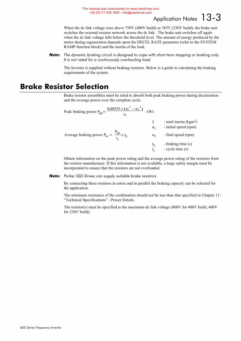
Application Notes 13-3
605 Series Frequency Inverter
When the dc link voltage rises above 750V (400V build) or 385V (230V build), the brake unit switches the external resistor network across the dc link. The brake unit switches off again when the dc link voltage falls below the threshold level. The amount of energy produced by the motor during regeneration depends upon the DECEL RATE parameter (refer to the SYSTEM RAMP function block) and the inertia of the load.
Note: The dynamic braking circuit is designed to cope with short term stopping or braking only. It is not rated for a continuously overhauling load.
The Inverter is supplied without braking resistors. Below is a guide to calculating the braking requirements of the system.
Brake Resistor Selection Brake resistor assemblies must be rated to absorb both peak braking power during deceleration and the average power over the complete cycle.
Peak braking power P0 0055J n n
tW1
22
2
b=
× −. ( )( )pk
J - total inertia (kgm2) n1 - initial speed (rpm)
Average braking power PPtavpk
c= x tb n2 - final speed (rpm)
tb - braking time (s) tc - cycle time (s) Obtain information on the peak power rating and the average power rating of the resistors from the resistor manufacturer. If this information is not available, a large safety margin must be incorporated to ensure that the resistors are not overloaded.
Note: Parker SSD Drives can supply suitable brake resistors.
By connecting these resistors in series and in parallel the braking capacity can be selected for the application.
The minimum resistance of the combination should not be less than that specified in Chapter 11: “Technical Specifications” - Power Details.
The resistor(s) must be specified to the maximum dc link voltage (800V for 400V build, 400V for 230V build).
This manual was downloaded on www.sdsdrives.com +44 (0)117 938 1800 - [email protected]

13-4 Application Notes
605 Series Frequency Inverter
This manual was downloaded on www.sdsdrives.com +44 (0)117 938 1800 - [email protected]
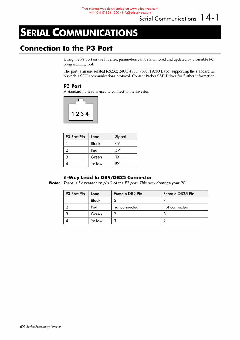
Serial Communications 14-1
605 Series Frequency Inverter
14SERIAL COMMUNICATIONS Connection to the P3 Port
Using the P3 port on the Inverter, parameters can be monitored and updated by a suitable PC programming tool.
The port is an un-isolated RS232; 2400, 4800, 9600, 19200 Baud; supporting the standard EI bisynch ASCII communications protocol. Contact Parker SSD Drives for further information.
P3 Port A standard P3 lead is used to connect to the Inverter.
1 2 3 4
P3 Port Pin Lead Signal
1 Black 0V
2 Red 5V
3 Green TX
4 Yellow RX
6-Way Lead to DB9/DB25 Connector Note: There is 5V present on pin 2 of the P3 port. This may damage your PC.
P3 Port Pin Lead Female DB9 Pin Female DB25 Pin
1 Black 5 7
2 Red not connected not connected
3 Green 2 3
4 Yellow 3 2
This manual was downloaded on www.sdsdrives.com +44 (0)117 938 1800 - [email protected]

14-2 Serial Communications
605 Series Frequency Inverter
This manual was downloaded on www.sdsdrives.com +44 (0)117 938 1800 - [email protected]
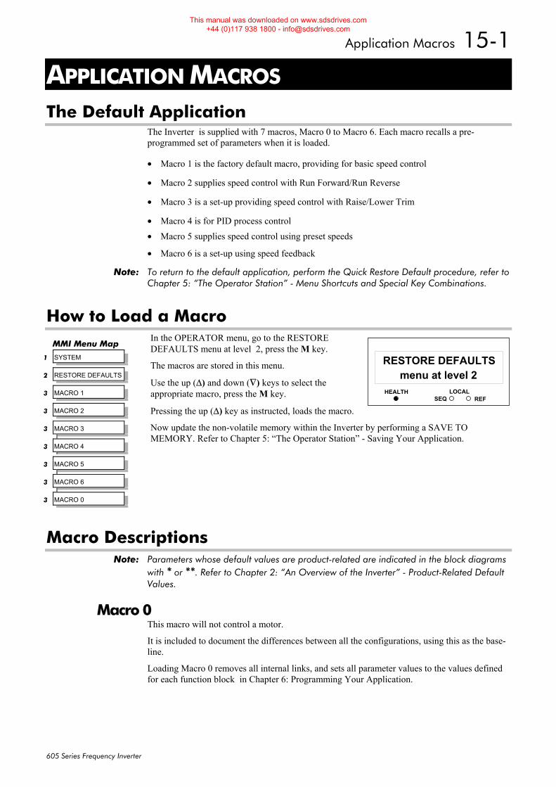
Application Macros 15-1
605 Series Frequency Inverter
15APPLICATION MACROS The Default Application
The Inverter is supplied with 7 macros, Macro 0 to Macro 6. Each macro recalls a pre-programmed set of parameters when it is loaded.
• Macro 1 is the factory default macro, providing for basic speed control
• Macro 2 supplies speed control with Run Forward/Run Reverse
• Macro 3 is a set-up providing speed control with Raise/Lower Trim
• Macro 4 is for PID process control • Macro 5 supplies speed control using preset speeds
• Macro 6 is a set-up using speed feedback
Note: To return to the default application, perform the Quick Restore Default procedure, refer to Chapter 5: “The Operator Station” - Menu Shortcuts and Special Key Combinations.
How to Load a Macro In the OPERATOR menu, go to the RESTORE DEFAULTS menu at level 2, press the M key.
The macros are stored in this menu.
Use the up (Δ) and down (∇) keys to select the appropriate macro, press the M key.
Pressing the up (Δ) key as instructed, loads the macro.
Now update the non-volatile memory within the Inverter by performing a SAVE TO MEMORY. Refer to Chapter 5: “The Operator Station” - Saving Your Application.
Macro Descriptions Note: Parameters whose default values are product-related are indicated in the block diagrams
with * or **. Refer to Chapter 2: “An Overview of the Inverter” - Product-Related Default Values.
Macro 0 This macro will not control a motor.
It is included to document the differences between all the configurations, using this as the base-line.
Loading Macro 0 removes all internal links, and sets all parameter values to the values defined for each function block in Chapter 6: Programming Your Application.
HEALTH LOCALSEQ REF
11menu at level 2
RESTORE DEFAULTSMMI Menu Map
1 SYSTEM
2 RESTORE DEFAULTS
3 MACRO 1
3 MACRO 2
3 MACRO 3
3 MACRO 4
3 MACRO 5
3 MACRO 6
3 MACRO 0
This manual was downloaded on www.sdsdrives.com +44 (0)117 938 1800 - [email protected]

15-2 Application Macros
605 Series Frequency Inverter
The OPERATOR Menu for Macro 0 The default OPERATOR menu is shown below.
SETPOINT (REMOTE)SPEED DEMANDDRIVE FREQUENCYMOTOR CURRENTLOADDC LINK VOLTSCURRENT LIMITINGENTER PASSWORD
STARTUP SCREEN
This manual was downloaded on www.sdsdrives.com +44 (0)117 938 1800 - [email protected]

Application Macros 15-3
605 Series Frequency Inverter
FALSE
0.00%
ANALOG INPUT 2
VALUE [ 25] –
BREAK [ 27] –
100.00% – [ 23] SCALE –
0.00% – [ 24] OFFSET –
0..+10V – [ 22] TYPE –
FALSE – [ 21] BREAK ENABLE –
0.00% – [ 26] BREAK VALUE –
FALSE
0.00%
ANALOG INPUT 1
VALUE [ 16] –
BREAK [ 18] –
100.00% – [ 14] SCALE –
0.00% – [ 15] OFFSET –
0..+10V – [ 13] TYPE –
FALSE – [ 12] BREAK ENABLE –
0.00% – [ 17] BREAK VALUE –
DIGITAL INPUT 1
VALUE [ 31] – FALSE
FALSE – [ 30] INVERT –
DIGITAL INPUT 3
VALUE [ 37] – FALSE
FALSE – [ 36] INVERT –
DIGITAL INPUT 5
VALUE [ 43] – FALSE
FALSE – [ 42] INVERT –
DIGITAL INPUT 2
VALUE [ 34] – FALSE
FALSE – [ 33] INVERT –
FALSE
DIGITAL INPUT 4
VALUE [ 40] –
TRUE – [ 39] INVERT –
SEQUENCING LOGIC
TRIPPED [289] – FALSE
RUNNING [285] – FALSE
JOGGING [302] – FALSE
STOPPING [303] – FALSE
OUTPUT CONTACTOR [286] – FALSE
SWITCH ON ENABLE [288] – FALSE
SWITCHED ON [306] – TRUE
READY [287] – FALSE
SYSTEM RESET [305] – TRUE
MAIN SEQ STATE [301] – NOT READY
REMOTE REV OUT [296] – FALSE
HEALTHY [274] – FALSE
FALSE – [291] RUN FWD –
FALSE – [292] RUN REV –
FALSE – [293] /STOP –
FALSE – [280] JOG –
TRUE – [276] DRIVE ENABLE –
TRUE – [277] /FAST STOP –
TRUE – [278] /COAST STOP –
FALSE – [294] REMOTE REVERSE –
FALSE – [282] REM TRIP RESET –
TRUE – [290] TRIP RST BY RUN –
FALSE – [283] POWER UP START –
SKIP FREQUENCIES
OUTPUT [346] – 0.0%
OUTPUT H z [363] – 0.0Hz
INPUT H z [362] – 0.0Hz
0.00% – [340] INPUT –
0.0Hz – [341] BAND 1 –
0.0Hz – [342] FREQUENCY 1 –
0.0Hz – [680] BAND 2 –
0.0Hz – [343] FREQUENCY 2 –
0.0Hz – [681] BAND 3 –
0.0Hz – [344] FREQUENCY 3 –
0.0Hz – [682] BAND 4 –
0.0Hz – [345] FREQUENCY 4 –
I/O TRIPS
FALSE – [234] EXTERNAL TRIP –
FALSE – [235] INPUT 1 BREAK –
FALSE – [236] INPUT 2 BREAK –
I*t TRIP
105.00% – [237] I*t THRESHOLD –
60s – [238] I*t TIME –
150.00% – [239] I*t UPPER LIMIT –
STALL TRIP
100.00% – [240] STALL LIMIT –
600.0s – [241] STALL TIME –
TRIPS STATUS
ACTIVE TRIPS [ 4] – 0000
WARNINGS [ 5] – 0000
FIRST TRIP [ 6] – NO TRIP
0600 – [231] DISABLED TRIPS –
TRIPS HISTORY
TRIP 1 [NEWEST] [500] – NO TRIP
TRIP 2 [501] – NO TRIP
TRIP 3 [502] – NO TRIP
TRIP 4 [503] – NO TRIP
TRIP 5 [504] – NO TRIP
TRIP 6 [505] – NO TRIP
TRIP 7 [506] – NO TRIP
TRIP 8 [507] – NO TRIP
TRIP 9 [508] – NO TRIP
TRIP 10 [OLDEST] [509] – NO TRIP
MINIMUM SPEED
OUTPUT [335] – 0.00%
0.00% – [336] INPUT –
-100.00% – [337] MINIMUM –
PROP. W/MIN. – [338] MODE –
JOG
10.0 s – [246] SETPOINT –
1.0s – [261] ACCEL RATE –
1.0s – [262] DECEL RATE –
ANALOG OUTPUT 1
0.00% – [ 45] VALUE –
100.00% – [ 46] SCALE –
0.00% – [ 47] OFFSET –
TRUE – [ 48] ABS –
0..+10V – [ 49] TYPE –
SETPOINT SCALE
OUTPUT [ 59] – 0.00% lf
0.00% – [ 58] INPUT –
* 50.0Hz – [ 57] MAX SPEED –
ZERO SPEED
AT ZERO SPEED [360] –
– [358] INPUT –
– [357] LEVEL –
– [359] BAND –
DIGITAL OUTPUT 1
FALSE – [ 52] VALUE –
TRUE – [ 51] INVERT –
DIGITAL OUTPUT 2
FALSE – [ 55] VALUE –
FALSE – [ 54] INVERT –
0.00%
VALUE FUNC 1
OUTPUT [133] –
0.00% – [130] INPUT A –
0.00% – [131] INPUT B –
0.00% – [132] INPUT C –
A+B+C – [134] TYPE –
RAISE/LOWER
OUTPUT [325] – 0.00%
FALSE – [327] RAISE INPUT –
FALSE – [328] LOWER INPUT –
10.0s – [326] RAMP RATE –
100.00% – [330] MAX VALUE –
-100.00% – [329] MIN VALUE –
0.00% – [331] RESET VALUE –
FALSE – [332] RESET –
REFERENCE
SPEED DEMAND [255] – 0.00%
SPEED SETPOINT [254] – 0.00%
REVERSE [256] – FALSE
LOCAL SETPOINT [247] – 0.00%
LOCAL REVERSE [250] – FALSE
COMMS SETPOINT [269] – 0.00%
0.00% – [245] REMOTE SETPOINT –
0.00% – [248] SPEED TRIM –
100.00% – [252] MAX SPEED CLAMP –
-100.00% – [253] MIN SPEED CLAMP –
FALSE – [243] TRIM IN LOCAL –
FALSE – [249] REMOTE REVERSE –
STOP
RAMPED – [279] RUN STOP MODE –
10.0s – [263] STOP RATE –
0.10% – [266] STOP ZERO SPEED –
0.500s – [284] STOP DELAY –
RAMPED – [304] FAST STOP MODE –
30.0s – [275] FAST STOP LIMIT –
0.1s – [264] FAST STOP RATE –
1200Hz/s – [126] FINAL STOP RATE –
(1) (8) (9)
(2)
(10) (14)
(15)
(16)
(18)
(12)
(13)
(11)
(3)
(4)
(5)
(6)
(7)
0.00%(17)
SYSTEM RAMP
RAMPING [698] – FALSE
LINEAR – [244] RAMP TYPE –
10.0s – [258] ACCEL RATE –
10.0s – [259] DECEL RATE –
10.0s – [267] SYMETRIC RATE –
FALSE – [268] SYMETRIC MODE –
FALSE – [260] RAMP HOLD –
TRUE – [691] SRAMP CONTINUOUS –
10.00% – [692] SRAMP ACCEL –
10.00% – [693] SRAMP DECEL –
10.00% – [694] SRAMP JERK 1 –
10.00% – [695] SRAMP JERK 2 –
10.00% – [696] SRAMP JERK 3 –
10.00% – [697] SRAMP JERK 4 –
0.50%
0.00%
FALSE
0%
Macro 1: Basic Speed Control (default)
This manual was downloaded on www.sdsdrives.com +44 (0)117 938 1800 - [email protected]
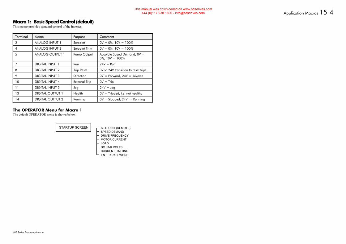
Application Macros 15-4
605 Series Frequency Inverter
Macro 1: Basic Speed Control (default) This macro provides standard control of the inverter.
Terminal Name Purpose Comment
2 ANALOG INPUT 1 Setpoint 0V = 0%, 10V = 100%
4 ANALOG INPUT 2 Setpoint Trim 0V = 0%, 10V = 100%
5 ANALOG OUTPUT 1 Ramp Output Absolute Speed Demand, 0V = 0%, 10V = 100%
7 DIGITAL INPUT 1 Run 24V = Run
8 DIGITAL INPUT 2 Trip Reset 0V to 24V transition to reset trips.
9 DIGITAL INPUT 3 Direction 0V = Forward, 24V = Reverse
10 DIGITAL INPUT 4 External Trip 0V = Trip
11 DIGITAL INPUT 5 Jog 24V = Jog
13 DIGITAL OUTPUT 1 Health 0V = Tripped, i.e. not healthy
14 DIGITAL OUTPUT 2 Running 0V = Stopped, 24V = Running
The OPERATOR Menu for Macro 1 The default OPERATOR menu is shown below.
SETPOINT (REMOTE)SPEED DEMANDDRIVE FREQUENCYMOTOR CURRENTLOADDC LINK VOLTSCURRENT LIMITINGENTER PASSWORD
STARTUP SCREEN
This manual was downloaded on www.sdsdrives.com +44 (0)117 938 1800 - [email protected]
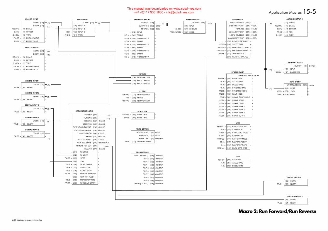
Application Macros 15-5
605 Series Frequency Inverter
FALSE
0.00%
ANALOG INPUT 2
VALUE [ 25] –
BREAK [ 27] –
100.00% – [ 23] SCALE –
0.00% – [ 24] OFFSET –
0..+10V – [ 22] TYPE –
FALSE – [ 21] BREAK ENABLE –
0.00% – [ 26] BREAK VALUE –
FALSE
0.00%
ANALOG INPUT 1
VALUE [ 16] –
BREAK [ 18] –
100.00% – [ 14] SCALE –
0.00% – [ 15] OFFSET –
0..+10V – [ 13] TYPE –
FALSE – [ 12] BREAK ENABLE –
0.00% – [ 17] BREAK VALUE –
DIGITAL INPUT 1
VALUE [ 31] – FALSE
FALSE – [ 30] INVERT –
DIGITAL INPUT 3
VALUE [ 37] – FALSE
FALSE – [ 36] INVERT –
DIGITAL INPUT 5
VALUE [ 43] – FALSE
FALSE – [ 42] INVERT –
DIGITAL INPUT 2
VALUE [ 34] – FALSE
FALSE – [ 33] INVERT –
FALSE
DIGITAL INPUT 4
VALUE [ 40] –
TRUE – [ 39] INVERT –
FALSE
FALSE
FALSE
FALSE
FALSE
FALSE
TRUE
FALSE
TRUE
FALSE
FALSE
SEQUENCING LOGIC
TRIPPED [289] –
RUNNING [285] –
JOGGING [302] –
STOPPING [303] –
OUTPUT CONTACTOR [286] –
SWITCH ON ENABLE [288] –
SWITCHED ON [306] –
READY [287] –
SYSTEM RESET [305] –
MAIN SEQ STATE [301] – NOT READY
REMOTE REV OUT [296] –
HEALTHY [274] –
FALSE – [291] RUN FWD –
FALSE – [292] RUN REV –
FALSE – [293] /STOP –
FALSE – [280] JOG –
TRUE – [276] DRIVE ENABLE –
TRUE – [277] /FAST STOP –
TRUE – [278] /COAST STOP –
FALSE – [294] REMOTE REVERSE –
FALSE – [282] REM TRIP RESET –
TRUE – [290] TRIP RST BY RUN –
FALSE – [283] POWER UP START –
SKIP FREQUENCIES
OUTPUT [346] – 0.0%
OUTPUT H z [363] – 0.0Hz
INPUT H z [362] – 0.0Hz
0.00% – [340] INPUT –
0.0Hz – [341] BAND 1 –
0.0Hz – [342] FREQUENCY 1 –
0.0Hz – [680] BAND 2 –
0.0Hz – [343] FREQUENCY 2 –
0.0Hz – [681] BAND 3 –
0.0Hz – [344] FREQUENCY 3 –
0.0Hz – [682] BAND 4 –
0.0Hz – [345] FREQUENCY 4 –
I/O TRIPS
FALSE – [234] EXTERNAL TRIP –
FALSE – [235] INPUT 1 BREAK –
FALSE – [236] INPUT 2 BREAK –
I*t TRIP
105.00% – [237] I*t THRESHOLD –
60s – [238] I*t TIME –
150.00% – [239] I*t UPPER LIMIT –
STALL TRIP
100.00% – [240] STALL LIMIT –
600.0s – [241] STALL TIME –
TRIPS STATUS
ACTIVE TRIPS [ 4] – 0000
WARNINGS [ 5] – 0000
FIRST TRIP [ 6] – NO TRIP
0600 – [231] DISABLED TRIPS –
TRIPS HISTORY
TRIP 1 [NEWEST] [500] – NO TRIP
TRIP 2 [501] – NO TRIP
TRIP 3 [502] – NO TRIP
TRIP 4 [503] – NO TRIP
TRIP 5 [504] – NO TRIP
TRIP 6 [505] – NO TRIP
TRIP 7 [506] – NO TRIP
TRIP 8 [507] – NO TRIP
TRIP 9 [508] – NO TRIP
TRIP 10 [OLDEST] [509] – NO TRIP
MINIMUM SPEED
OUTPUT [335] – 0.00%
0.00% – [336] INPUT –
-100.00% – [337] MINIMUM –
PROP. W/MIN. – [338] MODE –
JOG
– [246] SETPOINT –
1.0s – [261] ACCEL RATE –
1.0s – [262] DECEL RATE –
ANALOG OUTPUT 1
0.00% – [ 45] VALUE –
100.00% – [ 46] SCALE –
0.00% – [ 47] OFFSET –
TRUE – [ 48] ABS –
0..+10V – [ 49] TYPE –
SETPOINT SCALE
OUTPUT [ 59] – 0.00% lf
0.00% – [ 58] INPUT –
* 50.0Hz – [ 57] MAX SPEED –
ZERO SPEED
AT ZERO SPEED [360] –
– [358] INPUT –
– [357] LEVEL –
– [359] BAND –
DIGITAL OUTPUT 1
FALSE – [ 52] VALUE –
TRUE – [ 51] INVERT –
DIGITAL OUTPUT 2
FALSE – [ 55] VALUE –
FALSE – [ 54] INVERT –
0.00%
VALUE FUNC 1
OUTPUT [133] –
0.00% – [130] INPUT A –
0.00% – [131] INPUT B –
0.00% – [132] INPUT C –
A+B+C – [134] TYPE –
RAISE/LOWER
OUTPUT [325] – 0.00%
FALSE – [327] RAISE INPUT –
FALSE – [328] LOWER INPUT –
10.0s – [326] RAMP RATE –
100.00% – [330] MAX VALUE –
-100.00% – [329] MIN VALUE –
0.00% – [331] RESET VALUE –
FALSE – [332] RESET –
STOP
RAMPED – [279] RUN STOP MODE –
10.0s – [263] STOP RATE –
0.10% – [266] STOP ZERO SPEED –
0.500s – [284] STOP DELAY –
RAMPED – [304] FAST STOP MODE –
30.0s – [275] FAST STOP LIMIT –
0.1s – [264] FAST STOP RATE –
1200Hz/s – [126] FINAL STOP RATE –
REFERENCE
SPEED DEMAND [255] – 0.0 %
SPEED SETPOINT [254] – 0.00%
REVERSE [256] – FALSE
LOCAL SETPOINT [247] – 0.00%
LOCAL REVERSE [250] – FALSE
COMMS SETPOINT [269] – 0.00%
0.00% – [245] REMOTE SETPOINT –
0.00% – [248] SPEED TRIM –
100.00% – [252] MAX SPEED CLAMP –
-100.00% – [253] MIN SPEED CLAMP –
FALSE – [243] TRIM IN LOCAL –
FALSE – [249] REMOTE REVERSE –
(1) (8) (9)
(2)
(10) (14)
(15)
(16)
(18)
(12)
(13)
(11)
(3)
(4)
(5)
(6)
(7)
(17)
SYSTEM RAMP
RAMPING [698] – FALSE
LINEAR – [244] RAMP TYPE –
10.0s – [258] ACCEL RATE –
10.0s – [259] DECEL RATE –
10.0s – [267] SYMETRIC RATE –
FALSE – [268] SYMETRIC MODE –
FALSE – [260] RAMP HOLD –
TRUE – [691] SRAMP CONTINUOUS –
10.00% – [692] SRAMP ACCEL –
10.00% – [693] SRAMP DECEL –
10.00% – [694] SRAMP JERK 1 –
10.00% – [695] SRAMP JERK 2 –
10.00% – [696] SRAMP JERK 3 –
10.00% – [697] SRAMP JERK 4 –
0.50%
0.00%
FALSE
10.0 0%
Macro 2: Run Forward/Run Reverse
This manual was downloaded on www.sdsdrives.com +44 (0)117 938 1800 - [email protected]
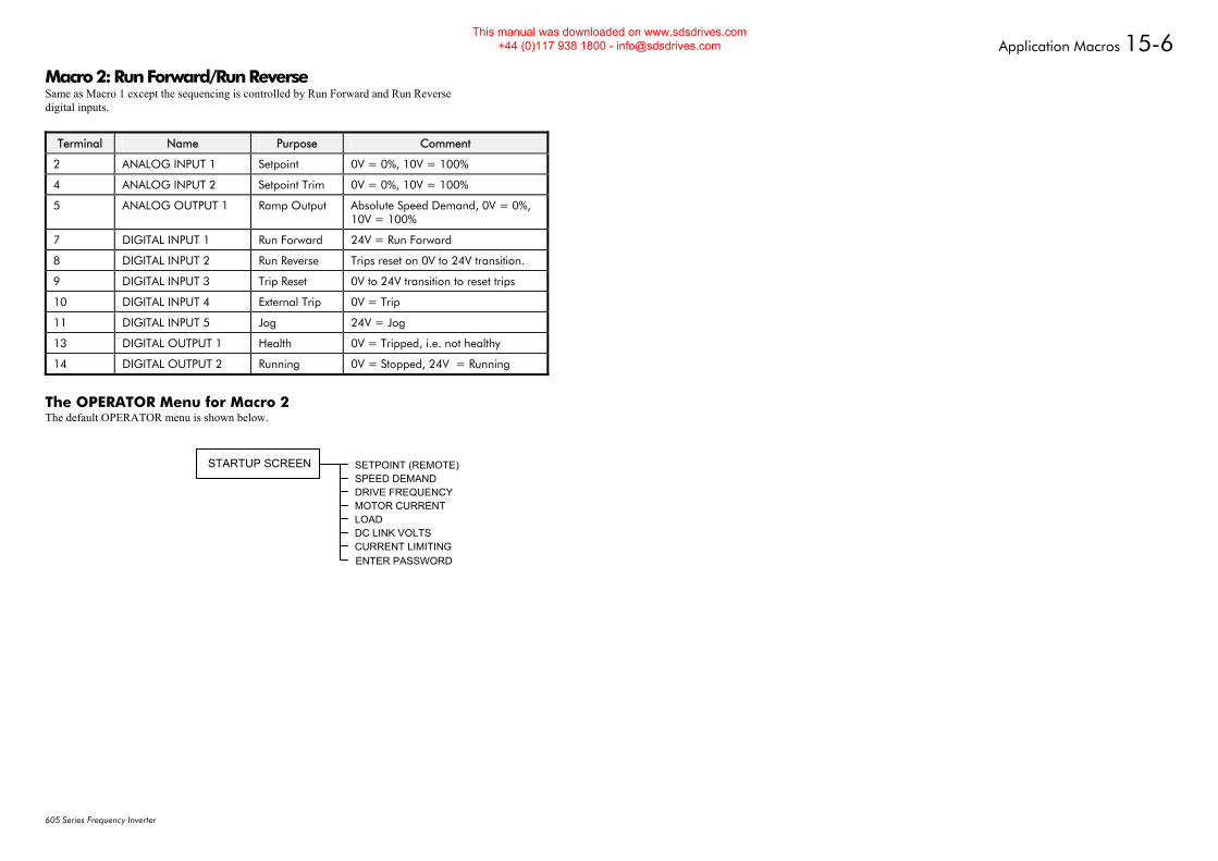
Application Macros 15-6
605 Series Frequency Inverter
Macro 2: Run Forward/Run Reverse Same as Macro 1 except the sequencing is controlled by Run Forward and Run Reverse digital inputs.
Terminal Name Purpose Comment
2 ANALOG INPUT 1 Setpoint 0V = 0%, 10V = 100%
4 ANALOG INPUT 2 Setpoint Trim 0V = 0%, 10V = 100%
5 ANALOG OUTPUT 1 Ramp Output Absolute Speed Demand, 0V = 0%, 10V = 100%
7 DIGITAL INPUT 1 Run Forward 24V = Run Forward
8 DIGITAL INPUT 2 Run Reverse Trips reset on 0V to 24V transition.
9 DIGITAL INPUT 3 Trip Reset 0V to 24V transition to reset trips
10 DIGITAL INPUT 4 External Trip 0V = Trip
11 DIGITAL INPUT 5 Jog 24V = Jog
13 DIGITAL OUTPUT 1 Health 0V = Tripped, i.e. not healthy
14 DIGITAL OUTPUT 2 Running 0V = Stopped, 24V = Running
The OPERATOR Menu for Macro 2 The default OPERATOR menu is shown below.
SETPOINT (REMOTE)SPEED DEMANDDRIVE FREQUENCYMOTOR CURRENTLOADDC LINK VOLTSCURRENT LIMITINGENTER PASSWORD
STARTUP SCREEN
This manual was downloaded on www.sdsdrives.com +44 (0)117 938 1800 - [email protected]
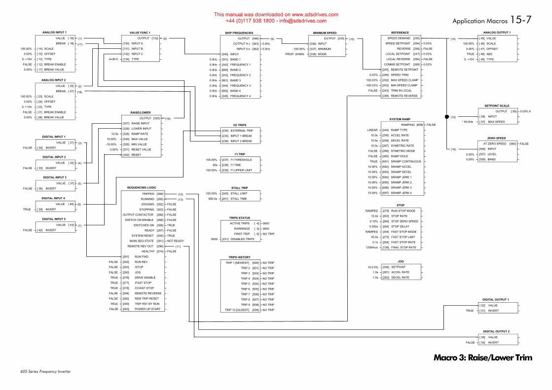
Application Macros 15-7
605 Series Frequency Inverter
FALSE
0.00%
ANALOG INPUT 2
VALUE [ 25] –
BREAK [ 27] –
100.00% – [ 23] SCALE –
0.00% – [ 24] OFFSET –
0..+10V – [ 22] TYPE –
FALSE – [ 21] BREAK ENABLE –
0.00% – [ 26] BREAK VALUE –
FALSE
0.00%
ANALOG INPUT 1
VALUE [ 16] –
BREAK [ 18] –
100.00% – [ 14] SCALE –
0.00% – [ 15] OFFSET –
0..+10V – [ 13] TYPE –
FALSE – [ 12] BREAK ENABLE –
0.00% – [ 17] BREAK VALUE –
DIGITAL INPUT 1
VALUE [ 31] – FALSE
FALSE – [ 30] INVERT –
DIGITAL INPUT 3
VALUE [ 37] – FALSE
FALSE – [ 36] INVERT –
DIGITAL INPUT 5
VALUE [ 43] – FALSE
FALSE – [ 42] INVERT –
DIGITAL INPUT 2
VALUE [ 34] – FALSE
FALSE – [ 33] INVERT –
FALSE
DIGITAL INPUT 4
VALUE [ 40] –
TRUE – [ 39] INVERT –
FALSE
FALSE
FALSE
FALSE
FALSE
FALSE
TRUE
FALSE
TRUE
FALSE
FALSE
SEQUENCING LOGIC
TRIPPED [289] –
RUNNING [285] –
JOGGING [302] –
STOPPING [303] –
OUTPUT CONTACTOR [286] –
SWITCH ON ENABLE [288] –
SWITCHED ON [306] –
READY [287] –
SYSTEM RESET [305] –
MAIN SEQ STATE [301] – NOT READY
REMOTE REV OUT [296] –
HEALTHY [274] –
FALSE – [291] RUN FWD –
FALSE – [292] RUN REV –
FALSE – [293] /STOP –
FALSE – [280] JOG –
TRUE – [276] DRIVE ENABLE –
TRUE – [277] /FAST STOP –
TRUE – [278] /COAST STOP –
FALSE – [294] REMOTE REVERSE –
FALSE – [282] REM TRIP RESET –
TRUE – [290] TRIP RST BY RUN –
FALSE – [283] POWER UP START –
SKIP FREQUENCIES
OUTPUT [346] – 0.0%
OUTPUT H z [363] – 0.0Hz
INPUT H z [362] – 0.0Hz
0.00% – [340] INPUT –
0.0Hz – [341] BAND 1 –
0.0Hz – [342] FREQUENCY 1 –
0.0Hz – [680] BAND 2 –
0.0Hz – [343] FREQUENCY 2 –
0.0Hz – [681] BAND 3 –
0.0Hz – [344] FREQUENCY 3 –
0.0Hz – [682] BAND 4 –
0.0Hz – [345] FREQUENCY 4 –
I/O TRIPS
FALSE – [234] EXTERNAL TRIP –
FALSE – [235] INPUT 1 BREAK –
FALSE – [236] INPUT 2 BREAK –
I*t TRIP
105.00% – [237] I*t THRESHOLD –
60s – [238] I*t TIME –
150.00% – [239] I*t UPPER LIMIT –
STALL TRIP
100.00% – [240] STALL LIMIT –
600.0s – [241] STALL TIME –
TRIPS STATUS
ACTIVE TRIPS [ 4] – 0000
WARNINGS [ 5] – 0000
FIRST TRIP [ 6] – NO TRIP
0600 – [231] DISABLED TRIPS –
TRIPS HISTORY
TRIP 1 [NEWEST] [500] – NO TRIP
TRIP 2 [501] – NO TRIP
TRIP 3 [502] – NO TRIP
TRIP 4 [503] – NO TRIP
TRIP 5 [504] – NO TRIP
TRIP 6 [505] – NO TRIP
TRIP 7 [506] – NO TRIP
TRIP 8 [507] – NO TRIP
TRIP 9 [508] – NO TRIP
TRIP 10 [OLDEST] [509] – NO TRIP
MINIMUM SPEED
OUTPUT [335] – 0.00%
0.00% – [336] INPUT –
-100.00% – [337] MINIMUM –
PROP. W/MIN. – [338] MODE –
JOG
– [246] SETPOINT –
1.0s – [261] ACCEL RATE –
1.0s – [262] DECEL RATE –
ANALOG OUTPUT 1
0.00% – [ 45] VALUE –
100.00% – [ 46] SCALE –
0.00% – [ 47] OFFSET –
TRUE – [ 48] ABS –
0..+10V – [ 49] TYPE –
SETPOINT SCALE
OUTPUT [ 59] – 0.00% lf
0.00% – [ 58] INPUT –
* 50.0Hz – [ 57] MAX SPEED –
ZERO SPEED
AT ZERO SPEED [360] –
– [358] INPUT –
– [357] LEVEL –
– [359] BAND –
DIGITAL OUTPUT 1
FALSE – [ 52] VALUE –
TRUE – [ 51] INVERT –
DIGITAL OUTPUT 2
FALSE – [ 55] VALUE –
FALSE – [ 54] INVERT –
0.00%
VALUE FUNC 1
OUTPUT [133] –
0.00% – [130] INPUT A –
0.00% – [131] INPUT B –
0.00% – [132] INPUT C –
A+B+C – [134] TYPE –
RAISE/LOWER
OUTPUT [325] – 0.00%
FALSE – [327] RAISE INPUT –
FALSE – [328] LOWER INPUT –
10.0s – [326] RAMP RATE –
10.00% – [330] MAX VALUE –
-10.00% – [329] MIN VALUE –
0.00% – [331] RESET VALUE –
FALSE – [332] RESET –
REFERENCE
SPEED DEMAND [255] – 0.00%
SPEED SETPOINT [254] – 0.00%
REVERSE [256] – FALSE
LOCAL SETPOINT [247] – 0.00%
LOCAL REVERSE [250] – FALSE
COMMS SETPOINT [269] – 0.00%
0.00% – [245] REMOTE SETPOINT –
0.00% – [248] SPEED TRIM –
100.00% – [252] MAX SPEED CLAMP –
-100.00% – [253] MIN SPEED CLAMP –
FALSE – [243] TRIM IN LOCAL –
FALSE – [249] REMOTE REVERSE –
STOP
RAMPED – [279] RUN STOP MODE –
10.0s – [263] STOP RATE –
0.10% – [266] STOP ZERO SPEED –
0.500s – [284] STOP DELAY –
RAMPED – [304] FAST STOP MODE –
30.0s – [275] FAST STOP LIMIT –
0.1s – [264] FAST STOP RATE –
1200Hz/s – [126] FINAL STOP RATE –
(1) (8) (9)
(2)
(10) (14)
(15)
(16)
(18)
(12)
(13)
(11)
(3)
(4)
(5)
(6)
(7)
(17)
0.00%0.00%(19) SYSTEM RAMP
RAMPING [698] – FALSE
LINEAR – [244] RAMP TYPE –
10.0s – [258] ACCEL RATE –
10.0s – [259] DECEL RATE –
10.0s – [267] SYMETRIC RATE –
FALSE – [268] SYMETRIC MODE –
FALSE – [260] RAMP HOLD –
TRUE – [691] SRAMP CONTINUOUS –
10.00% – [692] SRAMP ACCEL –
10.00% – [693] SRAMP DECEL –
10.00% – [694] SRAMP JERK 1 –
10.00% – [695] SRAMP JERK 2 –
10.00% – [696] SRAMP JERK 3 –
10.00% – [697] SRAMP JERK 4 –
0.50%
0.00%
FALSE
10.0 0%
Macro 3: Raise/Lower Trim
This manual was downloaded on www.sdsdrives.com +44 (0)117 938 1800 - [email protected]
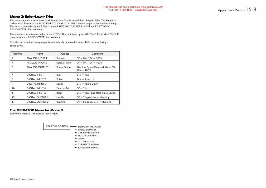
Application Macros 15-8
605 Series Frequency Inverter
Macro 3: Raise/Lower Trim This macro provides a raise/lower (push button) interface for an additional Setpoint Trim. The Setpoint is derived from the sum of ANALOG INPUT 1, ANALOG INPUT 2 and the output of the raise/lower ramp. This ramp is controlled by the 3 digital inputs RAISE INPUT, LOWER INPUT and RESET of the RAISE/LOWER function block.
The raise/lower trim is restricted to be +/- 10.00%. This limit is set by the MIN VALUE and MAX VALUE parameters in the RAISE/LOWER function block.
Note that the raise/lower ramp output is automatically preserved in non-volatile memory during a power-down.
Terminal Name Purpose Comment
2 ANALOG INPUT 1 Setpoint 0V = 0%, 10V = 100%
4 ANALOG INPUT 2 Setpoint Trim 0V = 0%, 10V = 100%
5 ANALOG OUTPUT 1 Ramp Output Absolute Speed Demand, 0V = 0%, 10V = 100%
7 DIGITAL INPUT 1 Run 24V = Run
8 DIGITAL INPUT 2 Raise 24V = Ramp Up
9 DIIGITAL INPUT 3 Lower 24V = Ramp Down
10 DIGITAL INPUT 4 External Trip 0V = Trip
11 DIGITAL INPUT 5 Reset 24V = Reset and Hold Raise Lower
13 DIGITAL OUTPUT 1 Health 0V = Tripped, i.e. not healthy
14 DIGITAL OUTPUT 2 Running 0V = Stopped, 24V = Running
The OPERATOR Menu for Macro 3 The default OPERATOR menu is shown below.
SETPOINT (REMOTE)SPEED DEMANDDRIVE FREQUENCYMOTOR CURRENTLOADDC LINK VOLTSCURRENT LIMITINGENTER PASSWORD
STARTUP SCREEN
This manual was downloaded on www.sdsdrives.com +44 (0)117 938 1800 - [email protected]
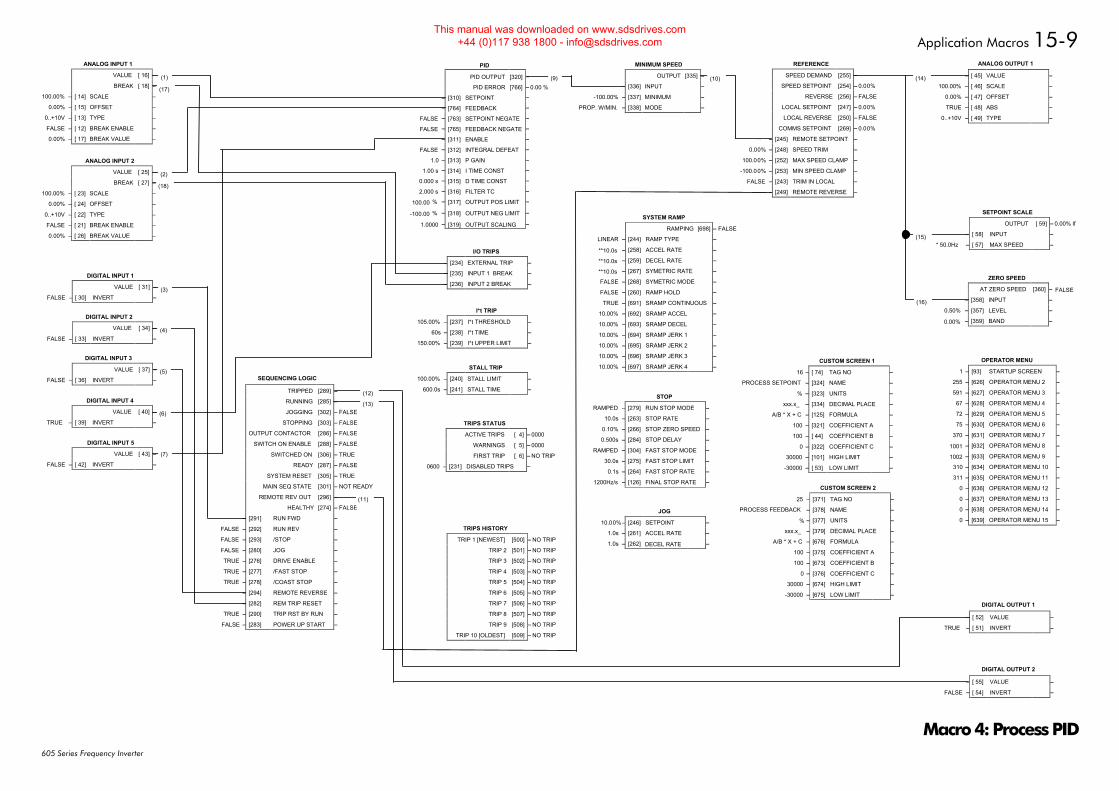
Application Macros 15-9
605 Series Frequency Inverter
FALSE
0.00%
ANALOG INPUT 2
VALUE [ 25] –
BREAK [ 27] –
100.00% – [ 23] SCALE –
0.00% – [ 24] OFFSET –
0..+10V – [ 22] TYPE –
FALSE – [ 21] BREAK ENABLE –
0.00% – [ 26] BREAK VALUE –
FALSE
0.00%
ANALOG INPUT 1
VALUE [ 16] –
BREAK [ 18] –
100.00% – [ 14] SCALE –
0.00% – [ 15] OFFSET –
0..+10V – [ 13] TYPE –
FALSE – [ 12] BREAK ENABLE –
0.00% – [ 17] BREAK VALUE –
DIGITAL INPUT 1
VALUE [ 31] – FALSE
FALSE – [ 30] INVERT –
DIGITAL INPUT 3
VALUE [ 37] – FALSE
FALSE – [ 36] INVERT –
DIGITAL INPUT 5
VALUE [ 43] – FALSE
FALSE – [ 42] INVERT –
DIGITAL INPUT 2
VALUE [ 34] – FALSE
FALSE – [ 33] INVERT –
FALSE
DIGITAL INPUT 4
VALUE [ 40] –
TRUE – [ 39] INVERT –
SEQUENCING LOGIC
TRIPPED [289] – FALSE
RUNNING [285] – FALSE
JOGGING [302] – FALSE
STOPPING [303] – FALSE
OUTPUT CONTACTOR [286] – FALSE
SWITCH ON ENABLE [288] – FALSE
SWITCHED ON [306] – TRUE
READY [287] – FALSE
SYSTEM RESET [305] – TRUE
MAIN SEQ STATE [301] – NOT READY
REMOTE REV OUT [296] – FALSE
HEALTHY [274] – FALSE
FALSE – [291] RUN FWD –
FALSE – [292] RUN REV –
FALSE – [293] /STOP –
FALSE – [280] JOG –
TRUE – [276] DRIVE ENABLE –
TRUE – [277] /FAST STOP –
TRUE – [278] /COAST STOP –
FALSE – [294] REMOTE REVERSE –
FALSE – [282] REM TRIP RESET –
TRUE – [290] TRIP RST BY RUN –
FALSE – [283] POWER UP START –
I/O TRIPS
FALSE – [234] EXTERNAL TRIP –
FALSE – [235] INPUT 1 BREAK –
FALSE – [236] INPUT 2 BREAK –
I*t TRIP
105.00% – [237] I*t THRESHOLD –
60s – [238] I*t TIME –
150.00% – [239] I*t UPPER LIMIT –
STALL TRIP
100.00% – [240] STALL LIMIT –
600.0s – [241] STALL TIME –
TRIPS HISTORY
TRIP 1 [NEWEST] [500] – NO TRIP
TRIP 2 [501] – NO TRIP
TRIP 3 [502] – NO TRIP
TRIP 4 [503] – NO TRIP
TRIP 5 [504] – NO TRIP
TRIP 6 [505] – NO TRIP
TRIP 7 [506] – NO TRIP
TRIP 8 [507] – NO TRIP
TRIP 9 [508] – NO TRIP
TRIP 10 [OLDEST] [509] – NO TRIP
MINIMUM SPEED
OUTPUT [335] – 0.00%
0.00% – [336] INPUT –
-100.00% – [337] MINIMUM –
PROP. W/MIN. – [338] MODE –
JOG
10.00%– [246] SETPOINT –
1.0s – [261] ACCEL RATE –
1.0s – [262] DECEL RATE –
ANALOG OUTPUT 1
0.00% – [ 45] VALUE –
100.00% – [ 46] SCALE –
0.00% – [ 47] OFFSET –
TRUE – [ 48] ABS –
0..+10V – [ 49] TYPE –
SETPOINT SCALE
OUTPUT [ 59] – 0.00% lf
0.00% – [ 58] INPUT –
* 50.0Hz – [ 57] MAX SPEED –
ZERO SPEED
AT ZERO SPEED [360] –
– [358] INPUT –
– [357] LEVEL –
– [359] BAND –
DIGITAL OUTPUT 1
FALSE – [ 52] VALUE –
TRUE – [ 51] INVERT –
DIGITAL OUTPUT 2
FALSE – [ 55] VALUE –
FALSE – [ 54] INVERT –
RAISE/LOWER
OUTPUT [325] – 0.00%
FALSE – [327] RAISE INPUT –
FALSE – [328] LOWER INPUT –
10.0s – [326] RAMP RATE –
100.00% – [330] MAX VALUE –
-100.00% – [329] MIN VALUE –
0.00% – [331] RESET VALUE –
FALSE – [332] RESET –
0.00%
REFERENCE
SPEED DEMAND [255] – 0.00%
SPEED SETPOINT [254] – 0.00%
REVERSE [256] – FALSE
LOCAL SETPOINT [247] – 0.00%
LOCAL REVERSE [250] – FALSE
COMMS SETPOINT [269] – 0.00%
0.00% – [245] REMOTE SETPOINT –
0.00% – [248] SPEED TRIM –
100.00% – [252] MAX SPEED CLAMP –
-100.00% – [253] MIN SPEED CLAMP –
FALSE – [243] TRIM IN LOCAL –
FALSE – [249] REMOTE REVERSE –
STOP
RAMPED – [279] RUN STOP MODE –
10.0s – [263] STOP RATE –
0.10% – [266] STOP ZERO SPEED –
0.500s – [284] STOP DELAY –
RAMPED – [304] FAST STOP MODE –
30.0s – [275] FAST STOP LIMIT –
0.1s – [264] FAST STOP RATE –
1200Hz/s – [126] FINAL STOP RATE –
(1) (9)
(2)
(10) (14)
(15)
(16)
(18)
(12)
(13)
(11)
(3)
(4)
(5)
(6)
(7)
(17)
SYSTEM RAMP
RAMPING [698] – FALSE
LINEAR – [244] RAMP TYPE –
**10.0s – [258] ACCEL RATE –
**10.0s – [259] DECEL RATE –
**10.0s – [267] SYMETRIC RATE –
FALSE – [268] SYMETRIC MODE –
FALSE – [260] RAMP HOLD –
TRUE – [691] SRAMP CONTINUOUS –
10.00% – [692] SRAMP ACCEL –
10.00% – [693] SRAMP DECEL –
10.00% – [694] SRAMP JERK 1 –
10.00% – [695] SRAMP JERK 2 –
10.00% – [696] SRAMP JERK 3 –
10.00% – [697] SRAMP JERK 4 –
0.50%
0.00%
FALSE
OPERATOR MENU
1 – [93] STARTUP SCREEN –
255 – [626] OPERATOR MENU 2 –
591 – [627] OPERATOR MENU 3 –
67 – [628] OPERATOR MENU 4 –
72 – [629] OPERATOR MENU 5 –
75 – [630] OPERATOR MENU 6 –
370 – [631] OPERATOR MENU 7 –
1001 – [632] OPERATOR MENU 8 –
1002 – [633] OPERATOR MENU 9 –
310 – [634] OPERATOR MENU 10 –
311 – [635] OPERATOR MENU 11 –
0 – [636] OPERATOR MENU 12 –
0 – [637] OPERATOR MENU 13 –
0 – [638] OPERATOR MENU 14 –
0 – [639] OPERATOR MENU 15 –
CUSTOM SCREEN 1
16 – [ 74] TAG NO –
– [324] NAME –
– [323] UNITS –
xxx.x_ – [334] DECIMAL PLACE –
A/B * X + C – [125] FORMULA –
100 – [321] COEFFICIENT A –
100 – [ 44] COEFFICIENT B –
0 – [322] COEFFICIENT C –
30000 – [101] HIGH LIMIT –
-30000 – [ 53] LOW LIMIT –
PROCESS SETPOINT
%
CUSTOM SCREEN 2
25 – [371] TAG NO –
– [378] NAME –
– [377] UNITS –
xxx.x_ – [379] DECIMAL PLACE –
A/B * X + C – [676] FORMULA –
100 – [375] COEFFICIENT A –
100 – [673] COEFFICIENT B –
0 – [376] COEFFICIENT C –
30000 – [674] HIGH LIMIT –
-30000 – [675] LOW LIMIT –
PROCESS FEEDBACK
%
PID
PID OUTPUT [320] –
PID ERROR [766] – 0.00 %
– [310] SETPOINT –
– [764] FEEDBACK –
FALSE – [763] SETPOINT NEGATE –
FALSE – [765] FEEDBACK NEGATE –
– [311] ENABLE –
FALSE – [312] INTEGRAL DEFEAT –
1.0 – [313] P GAIN –
1.00 s – [314] I TIME CONST –
0.000 s – [315] D TIME CONST –
2.000 s – [316] FILTER TC –
100.00 % – [317] OUTPUT POS LIMIT –
-100.00 % – [318] OUTPUT NEG LIMIT –
1.0000 – [319] OUTPUT SCALING –
TRIPS STATUS
ACTIVE TRIPS [ 4] – 0000
WARNINGS [ 5] – 0000
FIRST TRIP [ 6] – NO TRIP
0600 – [231] DISABLED TRIPS –
Macro 4: Process PID
This manual was downloaded on www.sdsdrives.com +44 (0)117 938 1800 - [email protected]
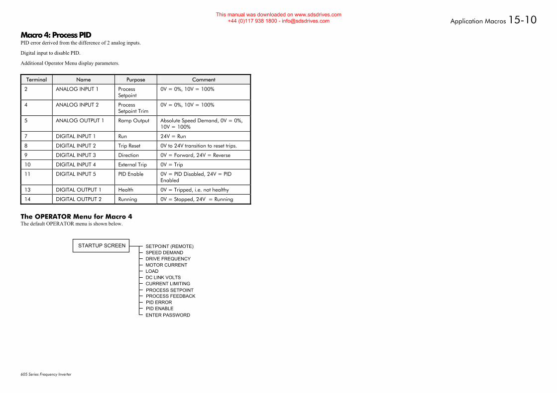
Application Macros 15-10
605 Series Frequency Inverter
Macro 4: Process PID PID error derived from the difference of 2 analog inputs.
Digital input to disable PID.
Additional Operator Menu display parameters.
Terminal Name Purpose Comment
2 ANALOG INPUT 1 Process Setpoint
0V = 0%, 10V = 100%
4 ANALOG INPUT 2 Process Setpoint Trim
0V = 0%, 10V = 100%
5 ANALOG OUTPUT 1 Ramp Output Absolute Speed Demand, 0V = 0%, 10V = 100%
7 DIGITAL INPUT 1 Run 24V = Run
8 DIGITAL INPUT 2 Trip Reset 0V to 24V transition to reset trips.
9 DIGITAL INPUT 3 Direction 0V = Forward, 24V = Reverse
10 DIGITAL INPUT 4 External Trip 0V = Trip
11 DIGITAL INPUT 5 PID Enable 0V = PID Disabled, 24V = PID Enabled
13 DIGITAL OUTPUT 1 Health 0V = Tripped, i.e. not healthy
14 DIGITAL OUTPUT 2 Running 0V = Stopped, 24V = Running
The OPERATOR Menu for Macro 4 The default OPERATOR menu is shown below.
SETPOINT (REMOTE)SPEED DEMANDDRIVE FREQUENCYMOTOR CURRENTLOADDC LINK VOLTSCURRENT LIMITINGPROCESS SETPOINT
STARTUP SCREEN
PROCESS FEEDBACKPID ERRORPID ENABLEENTER PASSWORD
This manual was downloaded on www.sdsdrives.com +44 (0)117 938 1800 - [email protected]
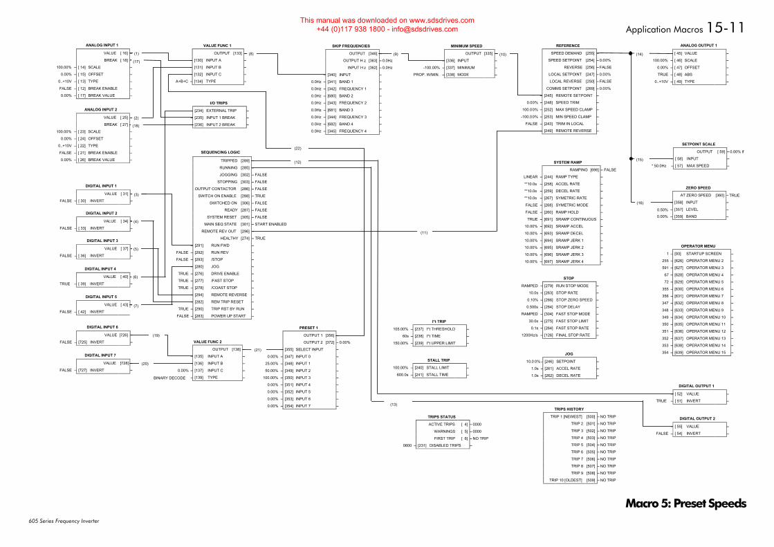
Application Macros 15-11
605 Series Frequency Inverter
FALSE
0.00%
ANALOG INPUT 2
VALUE [ 25] –
BREAK [ 27] –
100.00% – [ 23] SCALE –
0.00% – [ 24] OFFSET –
0..+10V – [ 22] TYPE –
FALSE – [ 21] BREAK ENABLE –
0.00% – [ 26] BREAK VALUE –
FALSE
0.00%
ANALOG INPUT 1
VALUE [ 16] –
BREAK [ 18] –
100.00% – [ 14] SCALE –
0.00% – [ 15] OFFSET –
0..+10V – [ 13] TYPE –
FALSE – [ 12] BREAK ENABLE –
0.00% – [ 17] BREAK VALUE –
DIGITAL INPUT 1
VALUE [ 31] – FALSE
FALSE – [ 30] INVERT –
DIGITAL INPUT 3
VALUE [ 37] – FALSE
FALSE – [ 36] INVERT –
DIGITAL INPUT 5
VALUE [ 43] – FALSE
FALSE – [ 42] INVERT
DIGITAL INPUT 2
VALUE [ 34] – FALSE
FALSE – [ 33] INVERT –
FALSE
DIGITAL INPUT 4
VALUE [ 40] –
TRUE – [ 39] INVERT –
FALSE
FALSE
FALSE
FALSE
FALSE
TRUE
FALSE
FALSE
FALSE
FALSE
TRUE
SEQUENCING LOGIC
TRIPPED [289] –
RUNNING [285] –
JOGGING [302] –
STOPPING [303] –
OUTPUT CONTACTOR [286] –
SWITCH ON ENABLE [288] –
SWITCHED ON [306] –
READY [287] –
SYSTEM RESET [305] –
MAIN SEQ STATE [301] – START ENABLED
REMOTE REV OUT [296] –
HEALTHY [274] –
FALSE – [291] RUN FWD –
FALSE – [292] RUN REV –
FALSE – [293] /STOP –
– [280] JOG –
TRUE – [276] DRIVE ENABLE –
TRUE – [277] /FAST STOP –
TRUE – [278] /COAST STOP –
– [294] REMOTE REVERSE –
– [282] REM TRIP RESET –
TRUE – [290] TRIP RST BY RUN –
FALSE – [283] POWER UP START –
SKIP FREQUENCIES
OUTPUT [346] – 0.0%
OUTPUT H z [363] – 0.0Hz
INPUT H z [362] – 0.0Hz
0.00% – [340] INPUT –
0.0Hz – [341] BAND 1 –
0.0Hz – [342] FREQUENCY 1 –
0.0Hz – [680] BAND 2 –
0.0Hz – [343] FREQUENCY 2 –
0.0Hz – [681] BAND 3 –
0.0Hz – [344] FREQUENCY 3 –
0.0Hz – [682] BAND 4 –
0.0Hz – [345] FREQUENCY 4 –
FALSE
FALSE
FALSE
I/O TRIPS
– [234] EXTERNAL TRIP –
– [235] INPUT 1 BREAK –
– [236] INPUT 2 BREAK –
I*t TRIP
105.00% – [237] I*t THRESHOLD –
60s – [238] I*t TIME –
150.00% – [239] I*t UPPER LIMIT –
STALL TRIP
100.00% – [240] STALL LIMIT –
600.0s – [241] STALL TIME –
TRIPS HISTORY
TRIP 1 [NEWEST] [500] – NO TRIP
TRIP 2 [501] – NO TRIP
TRIP 3 [502] – NO TRIP
TRIP 4 [503] – NO TRIP
TRIP 5 [504] – NO TRIP
TRIP 6 [505] – NO TRIP
TRIP 7 [506] – NO TRIP
TRIP 8 [507] – NO TRIP
TRIP 9 [508] – NO TRIP
TRIP 10 [OLDEST] [509] – NO TRIP
MINIMUM SPEED
OUTPUT [335] – 0.00%
0.00% – [336] INPUT –
-100.00% – [337] MINIMUM –
PROP. W/MIN. – [338] MODE –
JOG
10.0 0%– [246] SETPOINT –
1.0s – [261] ACCEL RATE –
1.0s – [262] DECEL RATE –
ANALOG OUTPUT 1
0.00% – [ 45] VALUE –
100.00% – [ 46] SCALE –
0.00% – [ 47] OFFSET –
TRUE – [ 48] ABS –
0..+10V – [ 49] TYPE –
SETPOINT SCALE
OUTPUT [ 59] – 0.00% lf
0.00% – [ 58] INPUT –
* 50.0Hz – [ 57] MAX SPEED –
ZERO SPEED
AT ZERO SPEED [360] –
– [358] INPUT –
– [357] LEVEL –
– [359] BAND –
DIGITAL OUTPUT 1
FALSE – [ 52] VALUE –
TRUE – [ 51] INVERT –
DIGITAL OUTPUT 2
FALSE – [ 55] VALUE –
FALSE – [ 54] INVERT –
0.00%
VALUE FUNC 1
OUTPUT [133] –
0.00% – [130] INPUT A –
0.00% – [131] INPUT B –
0.00% – [132] INPUT C –
A+B+C – [134] TYPE –
REFERENCE
SPEED DEMAND [255] – 0.00%
SPEED SETPOINT [254] – 0.00%
REVERSE [256] – FALSE
LOCAL SETPOINT [247] – 0.00%
LOCAL REVERSE [250] – FALSE
COMMS SETPOINT [269] – 0.00%
0.00% – [245] REMOTE SETPOINT –
0.00% – [248] SPEED TRIM –
100.00% – [252] MAX SPEED CLAMP –
-100.00% – [253] MIN SPEED CLAMP –
FALSE – [243] TRIM IN LOCAL –
FALSE – [249] REMOTE REVERSE –
STOP
RAMPED – [279] RUN STOP MODE –
10.0s – [263] STOP RATE –
0.10% – [266] STOP ZERO SPEED –
0.500s – [284] STOP DELAY –
RAMPED – [304] FAST STOP MODE –
30.0s – [275] FAST STOP LIMIT –
0.1s – [264] FAST STOP RATE –
1200Hz/s – [126] FINAL STOP RATE –
(1) (8) (9)
(2)
(10) (14)
(15)
(16)
(18)
(3)
(4)
(5)
(6)
(7)
(17)
SYSTEM RAMP
RAMPING [698] – FALSE
LINEAR – [244] RAMP TYPE –
**10.0s – [258] ACCEL RATE –
**10.0s – [259] DECEL RATE –
**10.0s – [267] SYMETRIC RATE –
FALSE – [268] SYMETRIC MODE –
FALSE – [260] RAMP HOLD –
TRUE – [691] SRAMP CONTINUOUS –
10.00% – [692] SRAMP ACCEL –
10.00% – [693] SRAMP DECEL –
10.00% – [694] SRAMP JERK 1 –
10.00% – [695] SRAMP JERK 2 –
10.00% – [696] SRAMP JERK 3 –
10.00% – [697] SRAMP JERK 4 –
0.50%
0.00%
TRUE
DIGITAL INPUT 6
VALUE [726] –
FALSE – [725] INVERT –
DIGITAL INPUT 7
VALUE [728] –
FALSE – [727] INVERT –
(12)
(13)
PRESET 1
OUTPUT 1 [356] –
OUTPUT 2 [372] – 0.00%
– [355] SELECT INPUT –
0.00% – [347] INPUT 0 –
25.00% – [348] INPUT 1 –
50.00% – [349] INPUT 2 –
100.00% – [350] INPUT 3 –
0.00% – [351] INPUT 4 –
0.00% – [352] INPUT 5 –
0.00% – [353] INPUT 6 –
0.00% – [354] INPUT 7 –
VALUE FUNC 2
OUTPUT [138] –
– [135] INPUT A –
– [136] INPUT B –
– [137] INPUT C –
BINARY DECODE – [139] TYPE –
(19)
(20)
(21)
(22)
OPERATOR MENU
1 – [93] STARTUP SCREEN –
255 – [626] OPERATOR MENU 2 –
591 – [627] OPERATOR MENU 3 –
67 – [628] OPERATOR MENU 4 –
72 – [629] OPERATOR MENU 5 –
355 – [630] OPERATOR MENU 6 –
356 – [631] OPERATOR MENU 7 –
347 – [632] OPERATOR MENU 8 –
348 – [633] OPERATOR MENU 9 –
349 – [634] OPERATOR MENU 10 –
350 – [635] OPERATOR MENU 11 –
351 – [636] OPERATOR MENU 12 –
352 – [637] OPERATOR MENU 13 –
353 – [638] OPERATOR MENU 14 –
354 – [639] OPERATOR MENU 15 –
(11)
TRIPS STATUS
ACTIVE TRIPS [ 4] – 0000
WARNINGS [ 5] – 0000
FIRST TRIP [ 6] – NO TRIP
0600 – [231] DISABLED TRIPS –
0.00%
Macro 5: Preset Speeds
This manual was downloaded on www.sdsdrives.com +44 (0)117 938 1800 - [email protected]
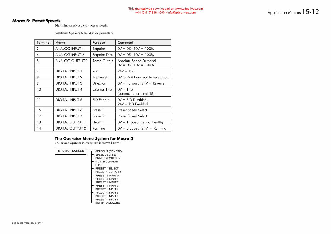
Application Macros 15-12
605 Series Frequency Inverter
Macro 5: Preset Speeds Digital inputs select up to 4 preset speeds. Additional Operator Menu display parameters.
Terminal Name Purpose Comment
2 ANALOG INPUT 1 Setpoint 0V = 0%, 10V = 100%
4 ANALOG INPUT 2 Setpoint Trim 0V = 0%, 10V = 100%
5 ANALOG OUTPUT 1 Ramp Output Absolute Speed Demand, 0V = 0%, 10V = 100%
7 DIGITAL INPUT 1 Run 24V = Run
8 DIGITAL INPUT 2 Trip Reset 0V to 24V transition to reset trips.
9 DIGITAL INPUT 3 Direction 0V = Forward, 24V = Reverse
10 DIGITAL INPUT 4 External Trip 0V = Trip (connect to terminal 18)
11 DIGITAL INPUT 5 PID Enable 0V = PID Disabled, 24V = PID Enabled
16 DIGITAL INPUT 6 Preset 1 Preset Speed Select
17 DIGITAL INPUT 7 Preset 2 Preset Speed Select
13 DIGITAL OUTPUT 1 Health 0V = Tripped, i.e. not healthy
14 DIGITAL OUTPUT 2 Running 0V = Stopped, 24V = Running
The Operator Menu System for Macro 5 The default Operator menu system is shown below.
SETPOINT (REMOTE)SPEED DEMANDDRIVE FREQUENCYMOTOR CURRENTLOADPRESET 1 SELECTPRESET 1 OUTPUT 1PRESET 1 INPUT 0
STARTUP SCREEN
PRESET 1 INPUT 1PRESET 1 INPUT 2PRESET 1 INPUT 3PRESET 1 INPUT 4PRESET 1 INPUT 5PRESET 1 INPUT 6PRESET 1 INPUT 7ENTER PASSWORD
This manual was downloaded on www.sdsdrives.com +44 (0)117 938 1800 - [email protected]
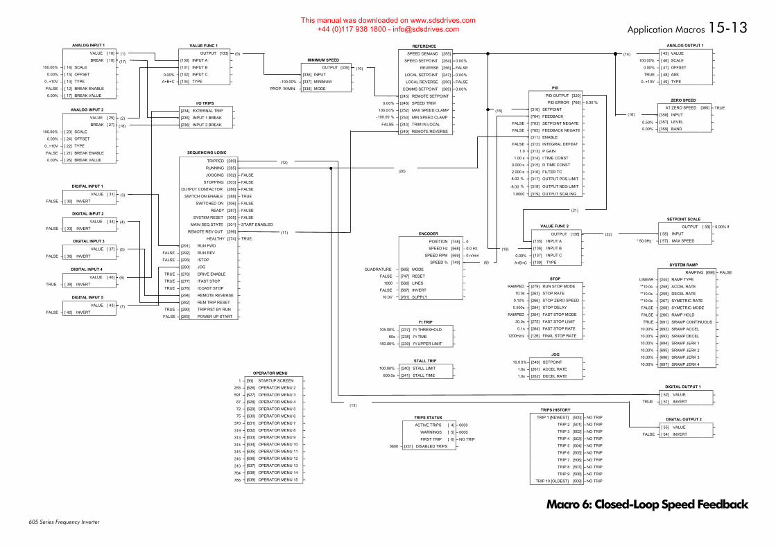
Application Macros 15-13
605 Series Frequency Inverter
FALSE
0.00%
ANALOG INPUT 2
VALUE [ 25] –
BREAK [ 27] –
100.00% – [ 23] SCALE –
0.00% – [ 24] OFFSET –
0..+10V – [ 22] TYPE –
FALSE – [ 21] BREAK ENABLE –
0.00% – [ 26] BREAK VALUE –
FALSE
0.00%
ANALOG INPUT 1
VALUE [ 16] –
BREAK [ 18] –
100.00% – [ 14] SCALE –
0.00% – [ 15] OFFSET –
0..+10V – [ 13] TYPE –
FALSE – [ 12] BREAK ENABLE –
0.00% – [ 17] BREAK VALUE –
DIGITAL INPUT 1
VALUE [ 31] – FALSE
FALSE – [ 30] INVERT –
DIGITAL INPUT 3
VALUE [ 37] – FALSE
FALSE – [ 36] INVERT –
DIGITAL INPUT 5
VALUE [ 43] – FALSE
FALSE – [ 42] INVERT
DIGITAL INPUT 2
VALUE [ 34] – FALSE
FALSE – [ 33] INVERT –
FALSE
DIGITAL INPUT 4
VALUE [ 40] –
TRUE – [ 39] INVERT –
FALSE
FALSE
FALSE
FALSE
FALSE
TRUE
FALSE
FALSE
FALSE
FALSE
TRUE
SEQUENCING LOGIC
TRIPPED [289] –
RUNNING [285] –
JOGGING [302] –
STOPPING [303] –
OUTPUT CONTACTOR [286] –
SWITCH ON ENABLE [288] –
SWITCHED ON [306] –
READY [287] –
SYSTEM RESET [305] –
MAIN SEQ STATE [301] – START ENABLED
REMOTE REV OUT [296] –
HEALTHY [274] –
FALSE – [291] RUN FWD –
FALSE – [292] RUN REV –
FALSE – [293] /STOP –
– [280] JOG –
TRUE – [276] DRIVE ENABLE –
TRUE – [277] /FAST STOP –
TRUE – [278] /COAST STOP –
– [294] REMOTE REVERSE –
– [282] REM TRIP RESET –
TRUE – [290] TRIP RST BY RUN –
FALSE – [283] POWER UP START –
FALSE
FALSE
FALSE
I/O TRIPS
– [234] EXTERNAL TRIP –
– [235] INPUT 1 BREAK –
– [236] INPUT 2 BREAK –
I*t TRIP
105.00% – [237] I*t THRESHOLD –
60s – [238] I*t TIME –
150.00% – [239] I*t UPPER LIMIT –
STALL TRIP
100.00% – [240] STALL LIMIT –
600.0s – [241] STALL TIME –
TRIPS HISTORY
TRIP 1 [NEWEST] [500] – NO TRIP
TRIP 2 [501] – NO TRIP
TRIP 3 [502] – NO TRIP
TRIP 4 [503] – NO TRIP
TRIP 5 [504] – NO TRIP
TRIP 6 [505] – NO TRIP
TRIP 7 [506] – NO TRIP
TRIP 8 [507] – NO TRIP
TRIP 9 [508] – NO TRIP
TRIP 10 [OLDEST] [509] – NO TRIP
MINIMUM SPEED
OUTPUT [335] – 0.00%
0.00% – [336] INPUT –
-100.00% – [337] MINIMUM –
PROP. W/MIN. – [338] MODE –
JOG
10.0 0%– [246] SETPOINT –
1.0s – [261] ACCEL RATE –
1.0s – [262] DECEL RATE –
ANALOG OUTPUT 1
0.00% – [ 45] VALUE –
100.00% – [ 46] SCALE –
0.00% – [ 47] OFFSET –
TRUE – [ 48] ABS –
0..+10V – [ 49] TYPE –
SETPOINT SCALE
OUTPUT [ 59] – 0.00% lf
0.00% – [ 58] INPUT –
* 50.0Hz – [ 57] MAX SPEED –
ZERO SPEED
AT ZERO SPEED [360] –
– [358] INPUT –
– [357] LEVEL –
– [359] BAND –
DIGITAL OUTPUT 1
FALSE – [ 52] VALUE –
TRUE – [ 51] INVERT –
DIGITAL OUTPUT 2
FALSE – [ 55] VALUE –
FALSE – [ 54] INVERT –
0.00%
VALUE FUNC 1
OUTPUT [133] –
0.00% – [130] INPUT A –
0.00% – [131] INPUT B –
0.00% – [132] INPUT C –
A+B+C – [134] TYPE –
REFERENCE
SPEED DEMAND [255] – 0.00%
SPEED SETPOINT [254] – 0.00%
REVERSE [256] – FALSE
LOCAL SETPOINT [247] – 0.00%
LOCAL REVERSE [250] – FALSE
COMMS SETPOINT [269] – 0.00%
0.00% – [245] REMOTE SETPOINT –
0.00% – [248] SPEED TRIM –
100.00% – [252] MAX SPEED CLAMP –
-100.00 % – [253] MIN SPEED CLAMP –
FALSE – [243] TRIM IN LOCAL –
– [249] REMOTE REVERSE –
STOP
RAMPED – [279] RUN STOP MODE –
10.0s – [263] STOP RATE –
0.10% – [266] STOP ZERO SPEED –
0.500s – [284] STOP DELAY –
RAMPED – [304] FAST STOP MODE –
30.0s – [275] FAST STOP LIMIT –
0.1s – [264] FAST STOP RATE –
1200Hz/s – [126] FINAL STOP RATE –
(1) (9)
(2)
(10)
(14)
(22)
(16)
(18)
(3)
(4)
(5)
(6)
(7)
(17)
SYSTEM RAMP
RAMPING [698] – FALSE
LINEAR – [244] RAMP TYPE –
**10.0s – [258] ACCEL RATE –
**10.0s – [259] DECEL RATE –
**10.0s – [267] SYMETRIC RATE –
FALSE – [268] SYMETRIC MODE –
FALSE – [260] RAMP HOLD –
TRUE – [691] SRAMP CONTINUOUS –
10.00% – [692] SRAMP ACCEL –
10.00% – [693] SRAMP DECEL –
10.00% – [694] SRAMP JERK 1 –
10.00% – [695] SRAMP JERK 2 –
10.00% – [696] SRAMP JERK 3 –
10.00% – [697] SRAMP JERK 4 –
0.50%
0.00%
TRUE
(12)
(13)
VALUE FUNC 2
OUTPUT [138] –
– [135] INPUT A –
– [136] INPUT B –
– [137] INPUT C –
A+B+C – [139] TYPE –
0.00%
(11)
0.00%
ENCODER
POSITION [748] – 0
SPEED Hz [568] – 0.0 Hz
SPEED RPM [569] – 0 n/min
SPEED % [749] –
QUADRATURE – [565] MODE –
FALSE – [747] RESET –
1000 – [566] LINES –
FALSE – [567] INVERT –
10.0V – [761] SUPPLY –
PID
PID OUTPUT [320] –
PID ERROR [766] – 0.00 %
– [310] SETPOINT –
– [764] FEEDBACK –
FALSE – [763] SETPOINT NEGATE –
FALSE – [765] FEEDBACK NEGATE –
– [311] ENABLE –
FALSE – [312] INTEGRAL DEFEAT –
1.0 – [313] P GAIN –
1.00 s – [314] I TIME CONST –
0.000 s – [315] D TIME CONST –
2.000 s – [316] FILTER TC –
8.00 % – [317] OUTPUT POS LIMIT –
-8.00 % – [318] OUTPUT NEG LIMIT –
1.0000 – [319] OUTPUT SCALING –
(8)
(20)
(15)
(19)
OPERATOR MENU
1 – [93] STARTUP SCREEN –
255 – [626] OPERATOR MENU 2 –
591 – [627] OPERATOR MENU 3 –
67 – [628] OPERATOR MENU 4 –
72 – [629] OPERATOR MENU 5 –
75 – [630] OPERATOR MENU 6 –
370 – [631] OPERATOR MENU 7 –
319 – [632] OPERATOR MENU 8 –
313 – [633] OPERATOR MENU 9 –
314 – [634] OPERATOR MENU 10 –
315 – [635] OPERATOR MENU 11 –
316 – [636] OPERATOR MENU 12 –
310 – [637] OPERATOR MENU 13 –
764 – [638] OPERATOR MENU 14 –
766 – [639] OPERATOR MENU 15 –
(21)
TRIPS STATUS
ACTIVE TRIPS [ 4] – 0000
WARNINGS [ 5] – 0000
FIRST TRIP [ 6] – NO TRIP
0600 – [231] DISABLED TRIPS –
Macro 6: Closed-Loop Speed Feedback
This manual was downloaded on www.sdsdrives.com +44 (0)117 938 1800 - [email protected]
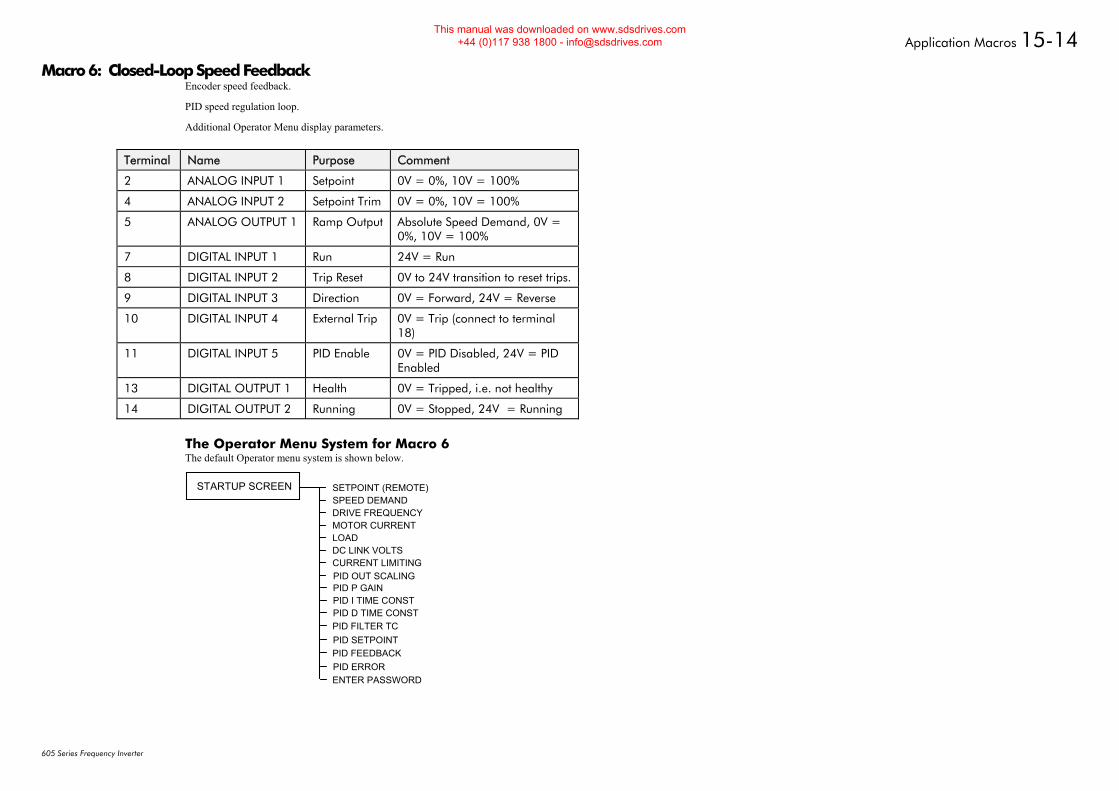
Application Macros 15-14
605 Series Frequency Inverter
Macro 6: Closed-Loop Speed Feedback Encoder speed feedback.
PID speed regulation loop.
Additional Operator Menu display parameters.
Terminal Name Purpose Comment
2 ANALOG INPUT 1 Setpoint 0V = 0%, 10V = 100%
4 ANALOG INPUT 2 Setpoint Trim 0V = 0%, 10V = 100%
5 ANALOG OUTPUT 1 Ramp Output Absolute Speed Demand, 0V = 0%, 10V = 100%
7 DIGITAL INPUT 1 Run 24V = Run
8 DIGITAL INPUT 2 Trip Reset 0V to 24V transition to reset trips.
9 DIGITAL INPUT 3 Direction 0V = Forward, 24V = Reverse
10 DIGITAL INPUT 4 External Trip 0V = Trip (connect to terminal 18)
11 DIGITAL INPUT 5 PID Enable 0V = PID Disabled, 24V = PID Enabled
13 DIGITAL OUTPUT 1 Health 0V = Tripped, i.e. not healthy
14 DIGITAL OUTPUT 2 Running 0V = Stopped, 24V = Running
The Operator Menu System for Macro 6 The default Operator menu system is shown below.
SETPOINT (REMOTE)SPEED DEMANDDRIVE FREQUENCYMOTOR CURRENTLOADDC LINK VOLTSCURRENT LIMITINGPID OUT SCALING
STARTUP SCREEN
PID P GAINPID I TIME CONSTPID D TIME CONSTPID FILTER TCPID SETPOINTPID FEEDBACKPID ERRORENTER PASSWORD
This manual was downloaded on www.sdsdrives.com +44 (0)117 938 1800 - [email protected]
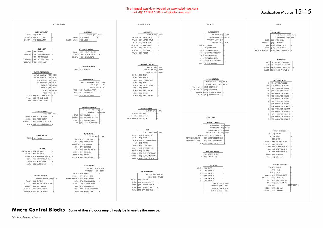
Application Macros 15-15
605 Series Frequency Inverter
AUTOTUNE
ACTIVE [604] –FALSE
FALSE – [603] ENABLE –
CALC NO LOAD I – [689] MODE –
CURRENT FEEDBACK
MOTOR CURRENT [ 66] – 0.00%
MOTOR CURRENT [ 67] – 0.0A
I MAGNETISING [ 68] – 0.00%
I MAGNETISING [ 69] – 0.0A
I TORQUE [ 70] – 0.00%
I TORQUE [ 71] – 0.0A
LOAD [ 72] – 0.00%
FIELD [ 73] – 0.00%
** 3.4A – [ 64] FULL LOAD CALIB –
** 1.9A – [ 65] NO LOAD CALIB –
0.80 – [242] POWER FACTOR –
CURRENT LIMIT
LIMITING [370] – FALSE
150.00% – [365] MOTOR I LIMIT –
-150.00% – [623] REGEN I LIMIT –
CURRENT – [366] FEEDBACK SOURCE –
TRUE – [686] REGEN LIM ENABLE –
DYNAMIC BRAKING
DC LINK VOLTS [ 75] – 0.0V
BRAKING [ 81] – FALSE
TRUE – [ 80] ENABLE –
100 Ohm – [ 77] BRAKE RESISTANCE –
0.1kW – [ 78] BRAKE POWER –
25 – [ 79] 1 SEC OVER RATING –
FLUXING
LINEAR LAW – [104] V/F SHAPE –
100.00% – [105] V/F SCALE –
* 50.0Hz – [106] BASE FREQUENCY –
120Hz – [113] LIMIT FREQUENCY –
0.00% – [107] FIXED BOOST –
0.00% – [108] AUTO BOOST –FLYCATCHING
ACTIVE [576] –FALSE
SETPOINT [ 28] –0.00%
FALSE – [570] ENABLE –
ALWAYS – [571] START MODE –
BIDIRECTIONAL – [572] SEARCH MODE –
9.00% – [573] SEARCH VOLTS –
35.00% – [ 32] SEARCH BOOST –
5.0s – [574] SEARCH TIME –
5.0Hz – [575] MIN SEARCH SPEED –
3.0s – [709] REFLUX TIME –
INJ BRAKING
ACTIVE [583] – FALSE
0.5s – [710] DEFLUX TIME –
9.0Hz – [577] FREQUENCY –
100.00% – [578] I-LIM LEVEL –
2.0s – [579] DC PULSE –
1.0s – [580] FINAL DC PULSE –
3.00% – [581] DC LEVEL –
–
100.00% [739] BASE VOLTS
–
SLEW RATE LIMIT
TRUE – [ 60] ENABLE –
500.0Hz/s – [ 62] ACCEL LIMIT –
500.0Hz/s – [ 61] DECEL LIMIT –
SLIP COMP
FALSE – [ 82] ENABLE –
1420 n/min – [ 83] NAMEPLATE RPM –
4 – [ 84] MOTOR POLES –
120.0 n/min – [ 85] MOTORING LIMIT –
120.0 n/min – [ 86] REGEN LIMIT –
STABILISATION
TRUE – [ 82] ENABLE –
UNDERLAP COMP
TRUE – [600] ENABLE –
VECTOR FLUXING
SUPPLY VOLTAGE [596] – 0.0V
FALSE – [118] ENABLE –
** DELTA – [124] MOTOR CONNECTION –
** 1.00 Ohm – [119] STATOR RES –
** 10.0mH – [120] LEAKAGE INDUC –
** 1000.0mH – [121] MUTUAL INDUC –
VOLTAGE CONTROL
NONE [595] VOLTAGE MODE –
** 230.0V – [122] MOTOR VOLTS –
100.00% – [112] BASE VOLTS –
BRAKE CONTROL
RELEASE [587] – FALSE
HOLD [590] – FALSE
50.00% – [584] ON LOAD –
5.0Hz – [585] ON FREQUENCY –
3.0Hz – [586] OFF FREQUENCY –
0.00s – [588] ON HOLD TIME –
0.00s – [589] OFF HOLD TIME –
MINIMUM SPEED
OUTPUT [335] – 0.00%
0.00% – [336] INPUT –
-100.00% – [337] MINIMUM –
PROP. W/MIN. – [338] MODE –
PID
PID OUTPUT [320] – 0.00%
0.00% – [310] ERROR INPUT –
FALSE – [311] ENABLE –
FALSE – [312] INTEGRAL DEFEAT –
1.0 – [313] P GAIN –
1.00s – [314] I TIME CONST –
0.000s – [315] D TIME CONST –
2.000s – [316] FILTER TC –
100.00% – [317] OUTPUT POS LIMIT –
-100.00% – [318] OUTPUT NEG LIMIT –
1.0000% – [319] OUTPUT SCALING –
RAISE/LOWER
OUTPUT [325] – 0.00%
FALSE – [327] RAISE INPUT –
FALSE – [328] LOWER INPUT –
10.0s – [326] RAMP RATE –
100.00% – [330] MAX VALUE –
-100.00% – [329] MIN VALUE –
0.00% – [331] RESET VALUE –
FALSE – [332] RESET –
SKIP FREQUENCIES
OUTPUT [346] – 0.0%
OUTPUT H z [363] – 0.0Hz
INPUT H z [362] – 0.0Hz
0.00% – [340] INPUT –
0.0Hz – [341] BAND1 –
0.0Hz – [342] FREQUENCY 1 –
0.0Hz – [680] BAND 2 –
0.0Hz – [343] FREQUENCY 2 –
0.0Hz – [681] BAND 3 –
0.0Hz – [344] FREQUENCY 3 –
0.0Hz – [682] BAND4 –
0.0Hz – [345] FREQUENCY 4 –
AUTO RESTART
PENDING [608] – FALSE
RESTARTING [616] – FALSE
ATTEMPTS LEFT [614] – 5
TIME LEFT [615] – 10.0s
FALSE – [611] ENABLE –
5 – [612] ATTEMPTS –
10.0s – [610] INITIAL DELAY 1 –
10.0s – [613] ATTEMPT DELAY 1 –
0000 – [609] TRIGGERS 1 –
0.1s – [678] INITIAL DELAY 2 –
0.1s – [679] ATTEMPT DELAY 2 –
0000 – [677] TRIGGERS 2 –
LOCAL CONTROL
REMOTE SEQ [297] –TRUE
REMOTE REF [257] –TRUE
LOCAL/REMOTE – [298] SEQ MODES –
LOCAL/REMOTE – [265] REF MODES –
REMOTE – [299] POWER UP MODE –
FALSE – [281] SEQ DIRECTION –
COMMS CONTROL
COMMS SEQ [295] – FALSE
COMMS REF [270] – FALSE
COMMS STATUS [272] – 0000
COMMS COMMAND [273] – 0000
FALSE – [300] REMOTE COMMS SEL –
TERMINALS/COMMS – [307] REMOTE SEQ MODES –
TERMINALS/COMMS – [308] REMOTE REF MODES –
0.0s – [309] COMMS TIMEOUT –
SYSTEM PORT (P3)
0 – [102] GROUP ID (GID) –
0 – [103] UNIT ID (UID) –
CUSTOM SCREEN 1
0 – [ 74] TAG NO –
– [324] NAME –
– [323] UNITS –
xxxxx. – [334] DECIMAL PLACE –
A/B * X + C – [125] FORMULA –
100 – [321] COEFFICIENT A –
100 – [ 44] COEFFICIENT B –
0 – [322] COEFFICIENT C –
30000 – [101] HIGH LIMIT –
-30000 – [ 53] LOW LIMIT –
CUSTOM SCREEN 2
0 – [371] TAG NO –
– [378] NAME –
– [377] UNITS –
xxxxx. – [379] DECIMAL PLACE –
A/B * X + C – [676] FORMULA –
100 – [375] COEFFICIENT A –
100 – [673] COEFFICIENT B –
0 – [376] COEFFICIENT C–
30000 – [674] HIGH LIMIT –
-30000 – [675] LOW LIMIT –
OPERATOR MENU
1 – [93] STARTUP SCREEN –
255 – [626] OPERATOR MENU 2 –
591 – [627] OPERATOR MENU 3 –
67 – [628] OPERATOR MENU 4 –
72 – [629] OPERATOR MENU 5 –
75 – [630] OPERATOR MENU 6 –
370 – [631] OPERATOR MENU 7 –
0 – [632] OPERATOR MENU 8 –
0 – [633] OPERATOR MENU 9 –
0 – [634] OPERATOR MENU 10 –
0 – [635] OPERATOR MENU 11 –
0 – [636] OPERATOR MENU 12 –
0 – [637] OPERATOR MENU 13 –
0 – [638] OPERATOR MENU 14 –
0 – [639] OPERATOR MENU 15 –
OP STATION
OP DATABASE [115] – FALSE
OP VERSION [230] – 0000
BASIC – [ 3] VIEW LEVEL –
* ENGLISH – [ 1] LANGUAGE –
00F0 – [127] ENABLED KEYS –
FALSE – [116] AUTO BACKUP –
* AC MOTOR DRIVE – [339] CONFIGURATION ID –
PASSWORD
ENTER PASSWORD[ 7]–0000
CHANGE PASSWORD[ 8]–0000
FALSE – [361] PROTECT LOCAL SP –
FALSE – [364] PROTECT OP MENU –
MOTOR CONTROL SETPOINT FUNCS
SERIAL LINKS
SEQ & REF MENUS
PATTERN GEN
DRIVE FREQUENCY [591] – 0.0Hz
VOLTS [592] – 0.0V
BOOST [593] – 0.0V
TRUE – [ 98] RANDOM PATTERN –
3kHz – [ 99] FREQ SELECT –
2.0s – [100] DEFLUX DELAY –
TEC OPTION
NONE – [750] TYPE –
0 – [751] INPUT 1 –
0 – [752] INPUT 2 –
0 – [753] INPUT 3 –
0 – [754] INPUT 4 –
0 – [755] INPUT 5 –
FAULT [756] – NONE
VERSION [757] – 0000
OUTPUT 1 [758] – 0000
OUTPUT 2 [759] – 0000
–
600.0s [582] TIMEOUT
––
Macro Control Blocks Some of these blocks may already be in use by the macros.
This manual was downloaded on www.sdsdrives.com +44 (0)117 938 1800 - [email protected]
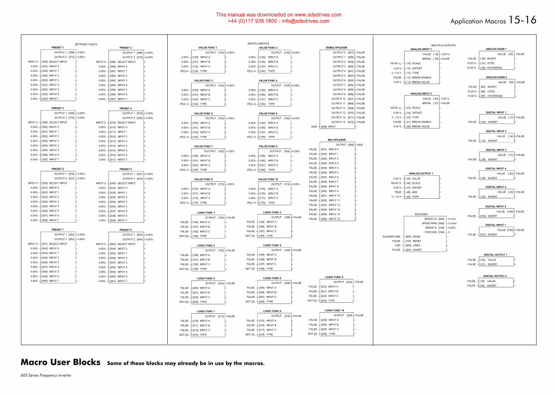
Application Macros 15-16
605 Series Frequency Inverter
PRESET 2
OUTPUT 1 [389] – 0.00%
OUTPUT 2 [373] – 0.00%
INPUT 0 – [388] SELECT INPUT –
0.00% – [380] INPUT 0 –
0.00% – [381] INPUT 1 –
0.00% – [382] INPUT 2 –
0.00% – [383] INPUT 3 –
0.00% – [384] INPUT 4 –
0.00% – [385] INPUT 5 –
0.00% – [386] INPUT 6 –
0.00% – [387] INPUT 7 –
PRESET 4
OUTPUT 1 [519] – 0.00%
OUTPUT 2 [520] – 0.00%
INPUT 0 – [518] SELECT INPUT –
0.00% – [510] INPUT 0 –
0.00% – [511] INPUT 1 –
0.00% – [512] INPUT 2 –
0.00% – [513] INPUT 3 –
0.00% – [514] INPUT 4 –
0.00% – [515] INPUT 5 –
0.00% – [516] INPUT 6 –
0.00% – [517] INPUT 7 –
PRESET 6
OUTPUT 1 [541] – 0.00%
OUTPUT 2 [542] – 0.00%
INPUT 0 – [540] SELECT INPUT –
0.00% – [532] INPUT 0 –
0.00% – [533] INPUT 1 –
0.00% – [534] INPUT 2 –
0.00% – [535] INPUT 3 –
0.00% – [536] INPUT 4 –
0.00% – [537] INPUT 5 –
0.00% – [538] INPUT 6 –
0.00% – [539] INPUT 7 –
PRESET 8
OUTPUT 1 [563] – 0.00%
OUTPUT 2 [564] – 0.00%
INPUT 0 – [562] SELECT INPUT –
0.00% – [554] INPUT 0 –
0.00% – [555] INPUT 1 –
0.00% – [556] INPUT 2 –
0.00% – [557] INPUT 3 –
0.00% – [558] INPUT 4 –
0.00% – [559] INPUT 5 –
0.00% – [560] INPUT 6 –
0.00% – [561] INPUT 7 –
PRESET 1
OUTPUT 1 [356] – 0.00%
OUTPUT 2 [372] – 0.00%
INPUT 0 – [355] SELECT INPUT –
0.00% – [347] INPUT 0 –
0.00% – [348] INPUT 1 –
0.00% – [349] INPUT 2 –
0.00% – [350] INPUT 3 –
0.00% – [351] INPUT 4 –
0.00% – [352] INPUT 5 –
0.00% – [353] INPUT 6 –
0.00% – [354] INPUT 7 –
PRESET 3
OUTPUT 1 [399] – 0.00%
OUTPUT 2 [374] – 0.00%
INPUT 0 – [398] SELECT INPUT –
0.00% – [390] INPUT 0 –
0.00% – [391] INPUT 1 –
0.00% – [392] INPUT 2 –
0.00% – [393] INPUT 3 –
0.00% – [394] INPUT 4 –
0.00% – [395] INPUT 5 –
0.00% – [396] INPUT 6 –
0.00% – [397] INPUT 7 –
PRESET 5
OUTPUT 1 [530] – 0.00%
OUTPUT 2 [531] – 0.00%
INPUT 0 – [529] SELECT INPUT –
0.00% – [521] INPUT 0 –
0.00% – [522] INPUT 1 –
0.00% – [523] INPUT 2 –
0.00% – [524] INPUT 3 –
0.00% – [525] INPUT 4 –
0.00% – [526] INPUT 5 –
0.00% – [527] INPUT 6 –
0.00% – [528] INPUT 7 –
PRESET 7
OUTPUT 1 [552] – 0.00%
OUTPUT 2 [553] – 0.00%
INPUT 0 – [551] SELECT INPUT –
0.00% – [543] INPUT 0 –
0.00% – [544] INPUT 1 –
0.00% – [545] INPUT 2 –
0.00% – [546] INPUT 3 –
0.00% – [547] INPUT 4 –
0.00% – [548] INPUT 5 –
0.00% – [549] INPUT 6 –
0.00% – [550] INPUT 7 –
VALUE FUNC 1
OUTPUT [133] – 0.00%
0.00% – [130] INPUT A –
0.00% – [131] INPUT B –
0.00% – [132] INPUT C –
IF[C]-A – [134] TYPE –
VALUE FUNC 3
OUTPUT [143] – 0.00%
0.00% – [140] INPUT A –
0.00% – [141] INPUT B –
0.00% – [142] INPUT C –
IF[C] -A – [144] TYPE –
VALUE FUNC 5
OUTPUT [153] – 0.00%
0.00% – [150] INPUT A –
0.00% – [151] INPUT B –
0.00% – [152] INPUT C –
IF[C] -A – [154] TYPE –
VALUE FUNC 7
OUTTPUT [163] – 0.00%
0.00% – [160] INPUT A –
0.00% – [161] INPUT B –
0.00% – [162] INPUT C –
IF[C] -A – [164] TYPE –
VALUE FUNC 9
OUTPUT [173] – 0.00%
0.00% – [170] INPUT A –
0.00% – [171] INPUT B –
0.00% – [172] INPUT C –
IF[C] -A – [174] TYPE –
VALUE FUNC 2
OUTPUT [138] –0.00%
0.00% – [135] INPUT A –
0.00% – [136] INPUT B –
0.00% – [137] INPUT C –
IF[C] -A – [139] TYPE –
VALUE FUNC 4
OUTPUT [148] –0.00%
0.00% – [145] INPUT A –
0.00% – [146] INPUT B –
0.00% – [147] INPUT C –
IF[C] -A – [149] TYPE –
VALUE FUNC 6
OUTPUT [158] –0.00%
0.00% – [155] INPUT A –
0.00% – [156] INPUT B –
0.00% – [157] INPUT C –
IF[C] -A – [159] TYPE –
VALUE FUNC 8
OUTTPUT [168] –0.00%
0.00% – [165] INPUT A –
0.00% – [166] INPUT B –
0.00% – [167] INPUT C –
IF[C] -A – [169] TYPE –
VALUE FUNC 10
OUTPUT [178] –0.00%
0.00% – [175] INPUT A –
0.00% – [176] INPUT B –
0.00% – [177] INPUT C –
IF[C] -A – [179] TYPE –
LOGIC FUNC 9
OUTPUT [223] – FALSE
FALSE – [220] INPUT A –
FALSE – [221] INPUT B –
FALSE – [222] INPUT C –
NOT [A] – [224] TYPE –
LOGIC FUNC 1
OUTPUT [183] – FALSE
FALSE – [180] INPUT A –
FALSE – [181] INPUT B –
FALSE – [182] INPUT C –
NOT [A] – [184] TYPE –
LOGIC FUNC 3
OUTPUT [193] – FALSE
FALSE – [190] INPUT A –
FALSE – [191] INPUT B –
FALSE – [192] INPUT C –
NOT [A] – [194] TYPE –
LOGIC FUNC 5
OUTPUT [203] – FALSE
FALSE – [200] INPUT A –
FALSE – [201] INPUT B –
FALSE – [202] INPUT C –
NOT [A] – [204] TYPE –
LOGIC FUNC 7
OUTPUT [213] – FALSE
FALSE – [210] INPUT A –
FALSE – [211] INPUT B –
FALSE – [212] INPUT C –
NOT [A] – [214] TYPE –
LOGIC FUNC 2
OUTPUT [188] – FALSE
FALSE – [185] INPUT A –
FALSE – [186] INPUT B –
FALSE – [187] INPUT C –
NOT [A] – [189] TYPE –
LOGIC FUNC 4
OUTPUT [198] – FALSE
FALSE – [195] INPUT A –
FALSE – [196] INPUT B –
FALSE – [197] INPUT C –
NOT [A] – [199] TYPE –
LOGIC FUNC 6
OUTPUT [208] – FALSE
FALSE – [205] INPUT A –
FALSE – [206] INPUT B –
FALSE – [207] INPUT C –
NOT [A] – [209] TYPE –
LOGIC FUNC 8
OUTPUT [218] – FALSE
FALSE – [215] INPUT A –
FALSE – [216] INPUT B –
FALSE – [217] INPUT C –
NOT [A] – [219] TYPE –
LOGIC FUNC 10
OUTPUT [228] – FALSE
FALSE – [225] INPUT A –
FALSE – [226] INPUT B –
FALSE – [227] INPUT C –
NOT [A] – [229] TYPE –
DEMULTIPLEXER
OUTPUT 0 [657] – FALSE
OUTPUT 1 [658] – FALSE
OUTPUT 2 [659] – FALSE
OUTPUT 3 [660] – FALSE
OUTPUT 4 [661] – FALSE
OUTPUT 5 [662] – FALSE
OUTPUT 6 [663] – FALSE
OUTPUT 7 [664] – FALSE
OUTPUT 8 [665] – FALSE
OUTPUT 9 [666] – FALSE
OUTPUT 10 [667] – FALSE
OUTPUT 11 [668] – FALSE
OUTPUT 12 [669] – FALSE
OUTPUT 13 [670] – FALSE
OUTPUT 14 [671] – FALSE
OUTPUT 15 [672] – FALSE
0000 – [599] INPUT –
MULTIPLEXER
OUTPUT [598] – 0000
FALSE – [641] INPUT 0 –
FALSE – [642] INPUT 1 –
FALSE – [643] INPUT 2 –
FALSE – [644] INPUT 3 –
FALSE – [645] INPUT 4 –
FALSE – [646] INPUT 5 –
FALSE – [647] INPUT 6 –
FALSE – [648] INPUT 7 –
FALSE – [649] INPUT 8 –
FALSE – [650] INPUT 9 –
FALSE – [651] INPUT 10 –
FALSE – [652] INPUT 11 –
FALSE – [653] INPUT 12 –
FALSE – [654] INPUT 13 –
FALSE – [655] INPUT 14 –
FALSE – [656] INPUT 15 –
SETPOINT FUNCS MISCELLANEOUS
ANALOG INPUT 1
VALUE [ 16] – 0.00 %
BREAK [ 18] – FALSE
100.00 % – [ 14] SCALE –
0.00 % – [ 15] OFFSET –
0..+10 V – [ 13] TYPE –
FALSE – [ 12] BREAK ENABLE –
0.00 % – [ 17] BREAK VALUE –
ANALOG INPUT 2
VALUE [ 25] – 0.00 %
BREAK [ 27] – FALSE
100.00 % – [ 23] SCALE –
0.00 % – [ 24] OFFSET –
0..+10 V – [ 22] TYPE –
FALSE – [ 21] BREAK ENABLE –
0.00 % – [ 26] BREAK VALUE –
ANALOG DIGIN 1
VALUE [ 90] – FALSE
FALSE – [ 89] INVERT –
70.00 % – [ 91] LEVEL –
10.00 % – [ 92] HYSTERISIS –
ANALOG DIGIN 2
VALUE [95] – FALSE
FALSE – [94] INVERT –
70.00 % – [96] LEVEL –
10.00 % – [97] HYSTERISIS –
ANALOG OUTPUT 1
0.00 % – [ 45] VALUE –
100.00 % – [ 46] SCALE –
0.00 % – [ 47] OFFSET –
TRUE – [ 48] ABS –
0..+10 V – [ 49] TYPE –
DIGITAL INPUT 1
VALUE [ 31] – FALSE
FALSE – [ 30] INVERT –
DIGITAL INPUT 3
VALUE [ 37] – FALSE
FALSE – [ 36] INVERT –
DIGITAL INPUT 5
VALUE [ 43] – FALSE
FALSE – [ 42] INVERT –
DIGITAL INPUT 2
VALUE [ 34] – FALSE
FALSE – [ 33] INVERT –
DIGITAL INPUT 4
VALUE [ 40] – FALSE
FALSE – [ 39] INVERT –
DIGITAL OUTPUT 1
FALSE – [ 52] VALUE –
FALSE – [ 51] INVERT –
DIGITAL OUTPUT 2
FALSE – [ 55] VALUE –
FALSE – [ 54] INVERT –
INPUTS & OUTPUTS
DIGITAL INPUT 7
VALUE [728] – FALSE
FALSE – [727] INVERT –
DIGITAL INPUT 6
VALUE [726] – FALSE
FALSE – [725] INVERT –ENCODER
SPEED Hz [568] – 0.0 Hz
SPEED RPM [569] – 0 n/min
SPEED % [749] – 0.00%
POSITION [748] – 0
QUADRATURE – [565] MODE –
FALSE – [747] RESET –
1000 – [566] LINES –
FALSE – [567] INVERT –
Macro User Blocks Some of these blocks may already be in use by the macros.
This manual was downloaded on www.sdsdrives.com +44 (0)117 938 1800 - [email protected]
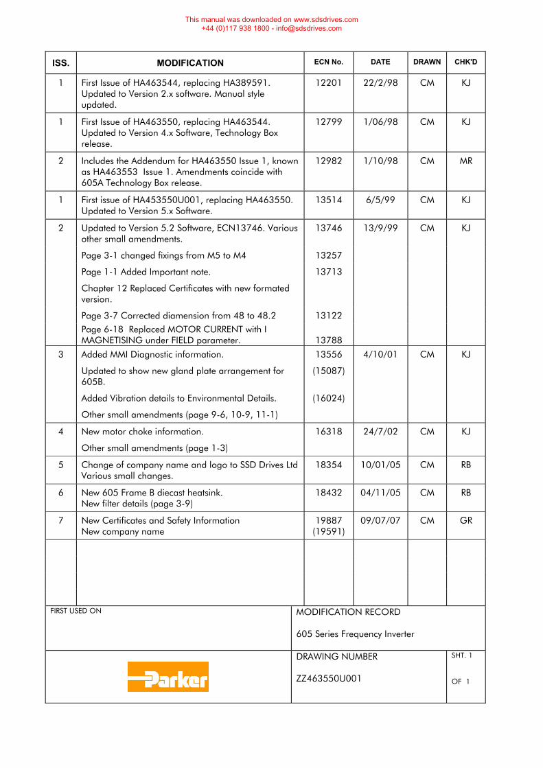
ISS. MODIFICATION ECN No. DATE DRAWN CHK'D
1 First Issue of HA463544, replacing HA389591. Updated to Version 2.x software. Manual style updated.
12201 22/2/98 CM KJ
1 First Issue of HA463550, replacing HA463544. Updated to Version 4.x Software, Technology Box release.
12799 1/06/98 CM KJ
2 Includes the Addendum for HA463550 Issue 1, known as HA463553 Issue 1. Amendments coincide with 605A Technology Box release.
12982 1/10/98 CM MR
1 First issue of HA453550U001, replacing HA463550. Updated to Version 5.x Software.
13514 6/5/99 CM KJ
2 Updated to Version 5.2 Software, ECN13746. Various other small amendments.
13746 13/9/99 CM KJ
Page 3-1 changed fixings from M5 to M4 13257
Page 1-1 Added Important note.
Chapter 12 Replaced Certificates with new formated version.
13713
Page 3-7 Corrected diamension from 48 to 48.2 13122 Page 6-18 Replaced MOTOR CURRENT with I
MAGNETISING under FIELD parameter.
13788
3 Added MMI Diagnostic information.
Updated to show new gland plate arrangement for 605B.
Added Vibration details to Environmental Details.
Other small amendments (page 9-6, 10-9, 11-1)
13556
(15087)
(16024)
4/10/01 CM KJ
4 New motor choke information.
Other small amendments (page 1-3)
16318 24/7/02 CM KJ
5 Change of company name and logo to SSD Drives LtdVarious small changes.
18354
10/01/05 CM RB
6 New 605 Frame B diecast heatsink. New filter details (page 3-9)
18432 04/11/05 CM RB
7 New Certificates and Safety Information New company name
19887 (19591)
09/07/07 CM GR
FIRST USED ON MODIFICATION RECORD
605 Series Frequency Inverter
DRAWING NUMBER ZZ463550U001
SHT. 1 OF 1
This manual was downloaded on www.sdsdrives.com +44 (0)117 938 1800 - [email protected]

This manual was downloaded on www.sdsdrives.com +44 (0)117 938 1800 - [email protected]
![A High-Frequency Resonant Inverter Topology with Low ... · PDF fileA High-Frequency Resonant Inverter Topology with ... the well-known class E inverter [12] uses resonant operation](https://img.pdfslide.us/doc/110x75/5a9f06527f8b9a76178c370c/a-high-frequency-resonant-inverter-topology-with-low-high-frequency-resonant.jpg)