Embed Size (px)
Citation preview

Scully ST-15 WXTechnical Manual
Multi-Point Liquid-Level Detection System
Scully Signal Company / Tel. 617 692 8600 / Fax. 617 692 8620 / 800 2 SCULLY (272 8559)70 Industrial Way, Wilmington, MA 01887-3479, USA / [email protected] / www.scully.com
MaxSafety®
SYSTEMS

ST-15-WX - Technical Manual
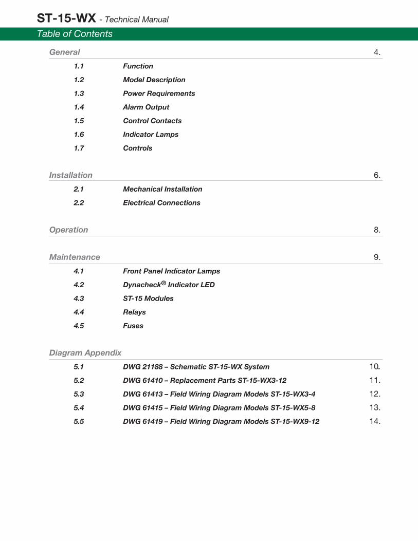
Table of Contents
General 4.
1.1 Function
1.2 Model Description
1.3 Power Requirements
1.4 Alarm Output
1.5 Control Contacts
1.6 Indicator Lamps
1.7 Controls
Installation 6.
2.1 Mechanical Installation
2.2 Electrical Connections
Operation 8.
Maintenance 9.
4.1 Front Panel Indicator Lamps
4.2 Dynacheck® Indicator LED
4.3 ST-15 Modules
4.4 Relays
4.5 Fuses
Diagram Appendix
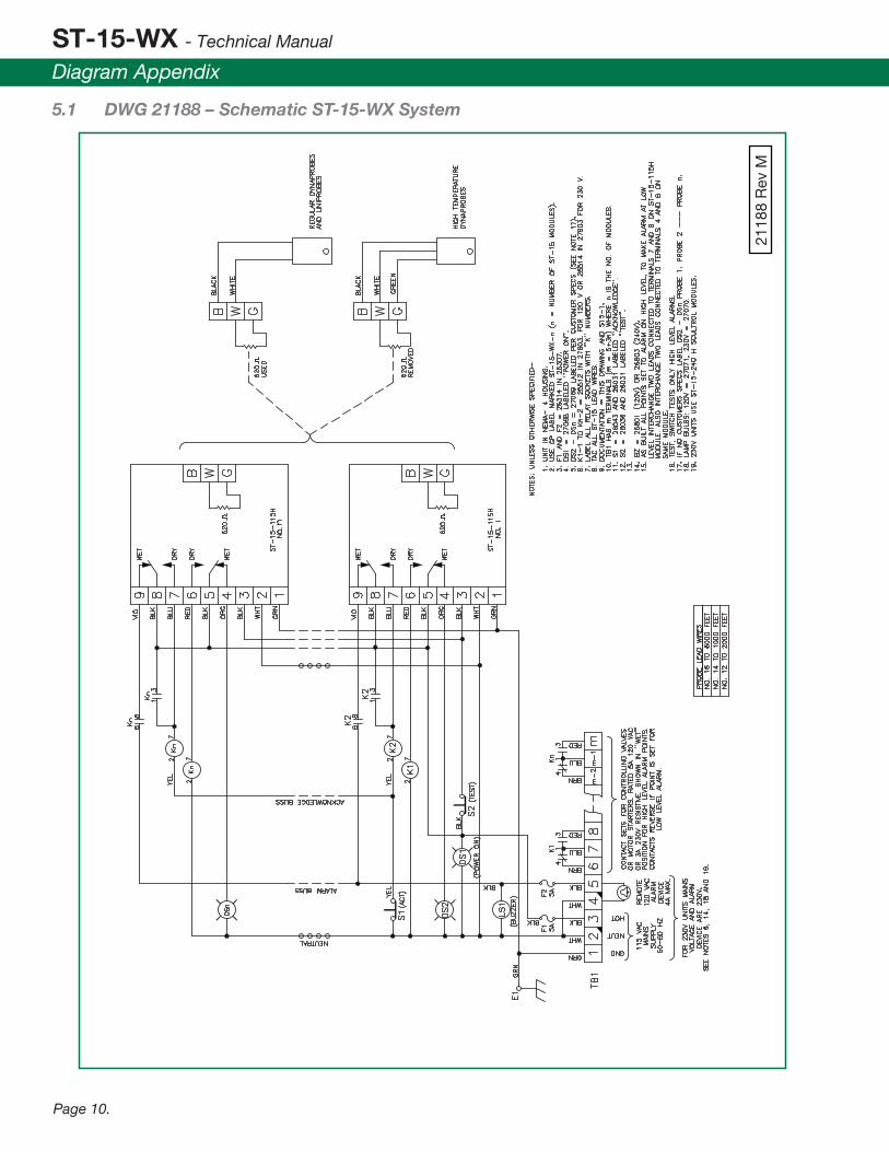
5.1 DWG 21188 – Schematic ST-15-WX System 10.
5.2 DWG 61410 – Replacement Parts ST-15-WX3-12 11.
5.3 DWG 61413 – Field Wiring Diagram Models ST-15-WX3-4 12.
5.4 DWG 61415 – Field Wiring Diagram Models ST-15-WX5-8 13.
5.5 DWG 61419 – Field Wiring Diagram Models ST-15-WX9-12 14.

ST-15-WX - Technical Manual
General
Page 4.
1.1 FUNCTION The ST-15C-WX series control units are multi-point liquid level alarm units. Typical applications are for high and/or low level alarm in xed storage tanks.
The Following is a listing of probe models that are compatable with the ST-15-WX:
The ST-15-WX control units can be mounted in any non-hazardous area and utlized oil tight controls and indicators. Internal circuitry provides intrinsically safe (I.S.) output, for pobe connections. This output is rated for Class 1, Div 1, Group D hazardous areas
1.2 Model Description The number following the “WX” denotes the number of ST-15C Control Modules in the model. Each module is referred to as a “channel” and can monitor one sensor. Thus, an ST-15-240-WX10 can monitor 10 probes.
The Scully part numbers for the various models are as follows:
Thermistors
Applicable Probes
Instant-On™Two-Wire Optic
SP-M SP-TOM
SP-MU SP-IO
SP-MH
SP-MH
SP-BL
SP-BLU
SP-BLH (Heated Products)
Model Part Number
ST-15-115-WX3 07851
ST-15-115-WX4 07852
ST-15-115-WX5 07853
ST-15-115-WX6 07854
ST-15-115-WX7 07855
ST-15-115-WX8 07856
ST-15-115-WX9 07857
ST-15-115-WX10 07858
ST-15-115-WX11 07859
ST-15-115-WX12 07860
Model Part Number
ST-15-230-WX3 07800
ST-15-230-WX4 07801
ST-15-230-WX5 07802
ST-15-230-WX6 07803
ST-15-230-WX7 07804
ST-15-230-WX8 07805
ST-15-230-WX9 07806
ST-15-230-WX10 07807
ST-15-230-WX11 07808
ST-15-230-WX12 07809

Multi-Point Liquid-Level Detection System
General
Page 5.
1.3 Power Requirements The ST-15C-WX units consume less than 20 watts of line power per channel exclusive of controlled circuits and alarm devices. Models ST-15-115-WX operate from100-140 VAC, 50-60Hz mains power, Models ST-15-230-WX operate from 200-250 VAC, 50-60 Hz mains power.
1.4 External Aalarm Output A mains voltage alarm output is applied whenever any channel trips to the alarm position. The alarm output is rated at 4 amps maximum current and is protected by an internal fuse.
When an alarm takes place, the alarm output line is energized and remains energized until either the alarm condition is corrected or the alarm acknowledge switch is operated. Operating the alarm acknowledge switch does not hinder subsequent alarms from other channels.
An alarm buzzer, internal to the enclosure is also included.
1.5 Control Contacts A Single Pole Double Throw (SPDT) volt-free contact set is provided on each ST-15 control unit, thus a contact is provided for each sensor. These contact sets are rated at 250 VAC, 5 amp resistive and may be used to control valves, motor starters or other electrical devices.
These contact sets are accessed through the unit’s main terminal strip.
1.6 Indicator Lamps
1.6.1 Power Lamp A green power pilot lamp indicates that mains power is being supplied to the units.
1.6.2 Alarm Indicator Lamps A single alarm indicator lamp is supplied for each channel in the unit. The legend plates on these lamps will have been engraved with customer-provided information (optional) identifying the function of each channel. These lamps light when an alarm condition takes place and will remain lit until the alarm condition is corrected. Acknowledging an alarm does not change the status of the associated alarm indicator lamp.
1.7 Controls
1.7.1 Alarm Acknowledge Button The ALARM ACKNOWLEDGE (silence) push button or optional key-operated acknowledge switch will silence the audible alarm devices when operated. The alarm acknowledging circuits reset automatically when the fault condition is corrected.
1.7.2 Test Push-Button The test button causes all high level alarm points to trip to their alarm condition when operated.

ST-15-WX - Technical Manual
Installation
Page 6.
2.1 Mechanical Installation The ST-15-WX control unit must be installed in a NON-HAZARDOUS AREA. Normally the unit is installed in the control room of a storage tank arena. It may be installed outdoors in its weather proof enclosure. Conduit entries must be properly sealed to keep water out of the enclosure.
2.2 Electrical Installation The most important thing to keep in mind when making electrical connections to the ST-15-WX control unit is to keep the intrinsically safe wiring to sensors separated from power and controlled circuit wiring. Separate conduit holes are provided and must be used to keep wiring separated.
THE IMPORTANCE OF MAINTAINING ABSOLUTE SEPARATION OF SENSOR (PROBE) LEADS AND OTHER WIRING CANNOT BE OVEREMPHASIZED!
See wiring diagrams in the Appendix (Section 5.0) for the specic model(s).
2.2.1 Power Connections Connect a source of main power to terminals 2 and 3 on Terminal Strip TB-1 inside the unit. See wiring diagram in Appendix (Section 5.0) for the specic model(s). Make sure that voltage matches the design voltage of the system.
Connect the earth lead to terminal 1 on TB-1
2.2.2 External Alarm Devices Connect mains voltage alarm horns, bells or sirens to terminals 4 and 5 on TB-1. Make sure the total connected load does not exceed 4 amps.
2.2.3 Control Device Connections The rest of the terminals, terminal 6 onwards, provide a SPDT relay contact, for each of the sensors as shown in the wiring diagram. Make sure that the connected loads do not exceed 5 amps resistive per contact set and that sources for these devices are used to prevent damage to the ST-15-WX equipment through eld wiring shorts for failures of controlled devices. Fuses internal to the unit do NOT protect the contacts.
2.2.4 Probe Connections
2.2.4.1 Two-Wire Probes The wiring diagram shows connections from TB2 of a ST-15 control module to a probe. When connecting to a 2-wire optic or thermister probe, the 680 Ω resister (factory installed) on terminals G and W should be kept connected.
2.2.4.2 Three-Wire Probes The wiring diagrams also show connections to 3-wire probe for heated products. The 680 Ω resister installed between the G and W terminals must be removed.
It is suggested that the resisiter be retained for future use.

Multi-Point Liquid-Level Detection System
Installation
Page 7.
2.2.4.3 Probe Lead Wire Size The following table should be used to determine the appropriate wire size for ST-15-WX Control Module to sensor connections for distance between ST-15-WX and the sensor.
CAUTION: If sensor leads are extended beyond 2500 feet, please consult the factory for specic wiring recommendations to prevent jeopardizing the intrinsically safe provisions of the system.
Wire Size Feet (MM2) Maximum Run Length Feet (Meters)
#16 (1.5) 400 (120)
#14 (2.5) 700 (210)
#12 (4.0) 1000 (300)
#10 (6.0) 1600 (480)
#8 (10.0) 2500 (760)

ST-15-WX - Technical Manual
Operation
Page 8.
3.1 ST-15-WX control units are shipped with each channel set to provide high level alarming (alarm output when liquid touches a probe). If your application requires alarm when a sensor becomes “dry”, typical for low level sensing, consult the factory for wiring instructions.
When system power is applied, all high-level alarm channels will produce alarm outputs (red lamp on and alarm buss energize) until their associated thermistor probes warm up. This will take approximately 10 seconds. (Note: warm up time varies with ambient temperature of air surrounding the probe) When a probe is “dry” and warmed up, the associated channel’s red lamp will go out. Two-wire optic probes do not require any warm-up time.
The sensor is NOT a “switch”. The ST-15-WX control unit will not respond and indicate “dry” with anything but a dry probe connected to its input terminals. Shorted or open probe circuits will not cause the ST-15-WX Control Unit to go “permissive”.

Multi-Point Liquid-Level Detection System
Maintenance
Page 9.
4.1 Front Panel Indicator Lamps These indicator lamps are changed by unscrewing the lens caps and replacing the bulbs beneath them.
4.2 Dynacheck® Indicator LED Each of the internal ST-15 control modules contains a Dynacheck® indicator lamp. (Scully part number 27002). The lampwill ash once every few seconds when the ST-15 Control unit is connected to a “dry” probe. The Dynacheck® indicator lamp is removed by pulling it straight out of its socket. Burnout of the Dynacheck® indicator LED will not affect the performance of the ST-15 module.
4.3 ST-15 Modules The ST-15 control modules contain no eld repacable components other than the Dynacheck® indicator LED. The modules must be removed as a unit and returned to the factory.
Note: returns to the factory must be accompanied by an RMA number- The RMA number must be obtained from Scully Signal Company
DO NOT ATTEMPT to service or adjust the ST-15-WX moduled without specic approval and instructions fro Scully Signal Company.
4.4 Relays Repace control relays only with equivalent types, making sure that the relays’ coil voltage matches the system voltage.
4.5 Fuses Do not replace fuse F1 and F2 with other than 5 amp slow-blow units.
ST-15-WX - Technical Manual
Diagram Appendix
5.1 DWG 21188 – Schematic ST-15-WX System
2118
8 R
ev M
Page 10.

Multi-Point Liquid-Level Detection System
Diagram Appendix
5.2 DWG 61410 – Replacement Parts ST-15-WX3-12
61410 Rev A
Page 11.

ST-15-WX - Technical Manual
Diagram Appendix
5.3 DWG 61413 – Field Wiring Diagram Models ST-15-WX3-4
6141
3 R
ev B
Page 12.

Multi-Point Liquid-Level Detection System
Diagram Appendix
5.4 DWG 61415 – Field Wiring Diagram Models ST-15-WX5-8
61415 Rev B
Page 13.

ST-15-WX - Technical Manual
Diagram Appendix
5.5 DWG 61419 – Field Wiring Diagram Models ST-15-WX9-12
61419 Rev B
Page 14.

Multi-Point Liquid-Level Detection System
Notes
Page 15.

Dynamic Self-Testing® Overll Prevention Systems
MaxSafety®
SYSTEMS
Scully Signal Company70 Industrial Way,Wilmington, MA 01887-3479, USA Tel: 800 272 8559 / 617 692 8600 email: [email protected]
Scully Systems Europe NVEksterveldlaan 31a2820 Bonheiden / Belgium Tel: +32 (0) 15 56 00 70 email: [email protected]
Scully UK LtdMeridian House, Unit 33,37 Road One Winsford Industrial Estate,Winsford Cheshire CW7 3QG / UK Tel: +44 (0) 1606 553805 email: [email protected]
For over seventy-ve years Scully has been engineering and building products
to the highest safety and reliability standards. We design and manufacture all of our
systems under one roof to ensure complete quality control over our manufacturing
and testing operations. Scully is ISO certied and all of our products are 100% made
in the U.S.A. In addition, we back up our products with the best service in the industry.
We have direct sales and service personnel in the U.S.A., The United Kingdom,
and Europe and are represented in over 50 countries.
For more information and 24 hour technical assistance,
call Scully Signal Company at 1-800-SCULLY (1-800-272-8559).
Scully Headquarters in Wilmington, MA U.S.A.
Copyright © 2014 Scully Signal Company. Intellitrol, Dynacheck, Dynamic Self-Checking,
Dynamic Self-Testing, Faylsafe, Intellicheck, MaxSafety, Scully, Scully Load Anywhere, T.I.M.,
and Ventalarm Signal are registered trademarks of Scully Signal Company. The names and
logos of other companies mentioned herein may be trademarkes of their respective owners.
This document is for informational purposes only. Scully makes no warranties, expressed
or implied, in this document. All Rights Reserved. Specications are subject to change without notice.
60323 Rev EOctober 2014
Scully - Setting Standards in Safety and Dependability Since 1936.