Embed Size (px)
Citation preview

20
Sarasota Detectors 2906 Corporate Way Palmetto, FL 34221 Ph: (800) 245-7660 Fax: (941) 845-1504
Email: [email protected] Web: www.peektraffic.com
81-998-2 1
601/602 Series Inductive Loop Detector
Installation Guide
Sarasota Series Detectors

2
Copyright © 2009 Peek Traffic Corporation Printed in the USA. All rights reserved. Information furnished by Peek is believed to be accurate and reliable, however Peek does not warranty the accuracy, completeness, or fitness for use of any of the information furnished. No license is granted by implication or otherwise under any intellectual property. Peek reserves the right to alter any of the Company's products or published technical data relating thereto at any time without notice. No part of this publication may be reproduced, stored in a retrieval system, or transmitted in any form or via any electronic or mechanical means for any purpose other than the purchaser’s personal use without the expressed, written permission of Peek Corporation Peek Corporation 2906 Corporate Way Palmetto, FL 34221 USA Trademarks The Sarasota Model 601/602 and 625 Series Detectors are trademarks or registered trademarks of Peek Corporation in the USA and other countries. Microsoft and Windows are trademarks or registered trademarks of Microsoft Corporation. Other brands and their products are trademarks or registered trademarks of their respective holders and should be noted as such.
Content:: 99-370-2 Assy: 81-998-2
19

18
Setup Details 1. Power is supplied to the unit on pins 7 & 8 (red and
black).
2. The most common hook-up is for using the presence relay, pins 4 & 5 (green and violet). The presence relay N.O. (normally open) pin 5 (violet) is connected to the Open, Close, Hold Open etc. (i.e. whichever function is to be performed.)
3. For a second presence or pulse output, relay 2, pins 1 & 2 (orange and blue,) are used. Relay 2 N.O. pin 2 (orange) is taken to the Open, Close, Hold Open etc. (whichever function is to be performed.) If a N.C. Nor-mally closed output is necessary, use pin 3 (yellow). Relay 2 common pin 1 (blue) is connected to the com-mon on the terminal strip of the operator.
4. The loop leads are on pins 9 & 10 (gray & brown). This is lead coming from the embedded loop in the ground. For proper operation, these leads must be twisted all the way to the detector.
Pin 1 Pin 10
3
Quick Setup 1. Verify the input voltage by the part number on the
silver label (located on the side of the oscillator cover.) 3NH = 120VAC 7NH = 24VAC
2. Make sure the harness is fitted correctly and snugly on the 10 pin molex connector.
3. With power applied, the bi-color LED should show green, indicating power is present. This same LED will show red during detection of a vehicle. (Red blinking indicates a loop fault. It will continue to blink until the detector is reset.)
4. Set sensitivity dial to medium (3 or 4).
5. Adjust the frequency to Low for a single loop (switch 1 and 2 to the ON position.) For multiple loop applica-tions, set each detector to a different frequency setting.

4
601/602 Definition of Outputs Presence means the relay will be energized the entire time a metal mass is within the field generated by the loops. The 601/602 has the ability to provide two outputs. Either relay can be set for presence or pulse. Relay 1 (pins 4 & 5, green and violet wires) can be set for presence using switch num-bers 3 & 4 on the board-mounted, 8 position, DIP switch. Set switch 3 to OFF and switch 4 to ON.
Pulse on Entry means that the relay will be energized as soon as a metal mass enters the field generated by the loop. Set switch 3 to OFF and switch 4 to OFF. This pulse will last 125mS.
Pulse on Exit means that the relay will be energized when a metal mass has left the loop. Set switch 3 to ON and switch 4 to OFF. The pulse will last 125mS.
Loop fault output means the relay will be energized if there is a current fault (open loop, shorted loop or greater than a 25% inductance change.)
SWITCHES 3 & 4 CONTROL OUTPUT MODE: OFF + ON = PRES. OFF + OFF = POE ON + OFF = POL ON + ON = FAULT
17
Loop Size
(ft) 1 Turn 2 Turns 3 Turns 4 Turns
6 × 4 8 25 56 100
6 × 6 10 31 70 124
6 × 10 14 43 96 171
6 × 15 19 58 129 229
6 × 20 24 72 161 286
6 × 25 29 87 194
6 × 30 34 101 226
6 × 35 38 116 259
6 × 40 43 130
6 × 45 48 145
6 × 50 53 159
6 × 55 58 173
6 × 60 63 188
6 × 65 67 202
6 × 70 72 217
6 × 75 77 231
6 × 80 82 246
6 × 85 87 260
6 × 90 91 275
6 × 95 96 289
Inductance(μH)*
6 × 100 101 303
6 Foot Loop Width
*optimum detection range is between 70μH and 250μH
16
Loop Size
(ft) 1 Turn 2 Turns 3 Turns 4 Turns
4 × 4 7 20 44 78
4 × 6 8 25 56 100
4 × 10 12 36 81 144
4 × 15 17 50 112 199
4 × 20 21 64 143 253
4 × 25 26 78 174
4 × 30 30 91 204
4 × 35 35 105 235
4 × 40 39 119 266
4 × 45 44 132
4 × 50 49 146
4 × 55 53 160
4 × 60 58 174
4 × 65 62 187
4 × 70 67 201
4 × 75 71 215
4 × 80 76 228
4 × 85 81 242
4 × 90 85 256
4 × 95 90 270
Inductance(μH)*
4 × 100 94 283
4 Foot Loop Width
*optimum detection range is between 70μH and 250μH
5
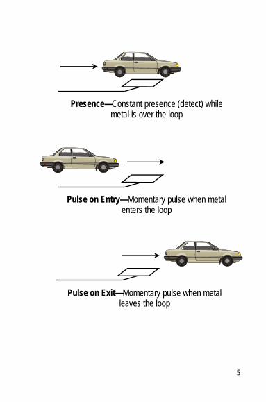
Presence—Constant presence (detect) while metal is over the loop
Pulse on Exit—Momentary pulse when metal leaves the loop
Pulse on Entry—Momentary pulse when metal enters the loop
6
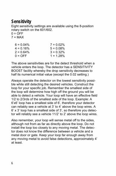
Sensitivity Eight sensitivity settings are available using the 8-position rotary switch on the 601/602. 0 = OFF 7 = MAX 6 = 0.04% 7 = 0.02% 4 = 0.16% 5 = 0.08% 2 = 0.64% 3 = 0.32% 0 = OFF 1 = 1.28% The above sensitivities are for the detect threshold when a vehicle enters the loop. The detector has a SENSITIVITY BOOST facility whereby the drop sensitivity decreases to half its numerical initial value (except the 0.02 setting.)
Always operate the detector on the lowest sensitivity possi-ble while still detecting the desired vehicles. Construct the loop for your specific job. Remember the smallest side of the loop will determine how high off the ground you will be able to detect a vehicle. Your loop will have an effective field 1/2 to 2/3rds of the smallest side of the loop. Example: A 6’x6’ loop has a smallest side of 6’, therefore your detector can reliably see a vehicle at 3’ to 4’ above the loop wires. A 6’ x 3’ loop has a smallest side of 3’, so therefore you detec-tor will reliably see a vehicle 11/2’ to 2’ above the loop wires.
Also remember, your loop will sense metal off to the sides, although not from as far as directly above the loop. Do not install the loop too closely to any moving metal. The detec-tor does not know the difference between a vehicle and a metal door or gate. Keep your loop far enough away from any moving metal to avoid false detections, approximately 4’ at least.
15
Loop Installation Tips The loop consists of a 12 to 18 gauge stranded wire suitable for direct burial with low AC and DC resistance. The size of your loop will be determined by the width of the area in which you need detection, and the height of the vehicles you need to detect. If high-bed trucks will be detected, the loop should be no less than 6’ on a side (i.e. at least 6’×6’.)
Smaller loops are suitable for car or fork truck detection. The depth of the saw cut is typically 1¼” to 2”, and from ¼” to 3/8” wide. Cut the corners of the loop to 45° angles to avoid pulling loop wires around a 90° corner and risk dam-aging the wires. Do no push the loop wires into the saw-cut with a sharp object. Be sure to keep the loops a minimum of 2” above any rebar or wire mesh installed in the roadway.
The loop wire is wound to form a coil (usually 3 to 5 turns.) Ideally, there should be no splices in the loop. Or, in other words, attach your loop wire to the gray wire in the wiring harness, run the loop out to your saw-cut, go around the saw cut the recommended number of times, return the loop wire back to the detector. Twist the lead-in portion of the loop wires at least 5 to 7 twists per foot, and then connect the other end of the loop wire to the brown wire on the wir-ing harness. The lead-ins and loop should be made of one continuous piece of wire.
Important: Twist only the lead-in (the part of the loop wire that runs from the edge of the loop back to the detector.) Do not twist the wires in the loops themselves.

14
Troubleshooting Q: The detector LED blinks red, and it won’t detect anything.
A: A blinking red LED is telling us there is a problem tuning the loop. An open loop, shorted loop, bad connection to the harness, loop wires twisted around the entire loop and not just the lead-in, or not enough turns in the loop are possible causes.
Q: The detector won’t let the door or gate down, it just reverses and goes back up
A: The loop has been installed too close to the door. A loop detector does not know the difference between a vehicle and a moving metal door or gate. If turning down the sensi-tivity does not help, consult the factory or move the loop farther away from the metal object, at least 4 feet away.
Q: The detector doesn’t detect trucks
The sensitivity is not high enough or the loop is too small to detect the generally higher metal chassis of a truck. Adjust the sensitivity or increase the size of the loop so that it can detect the truck. A loop can typically detect any metal that is less than 1/2 to 1/3 the distance of the smallest side of the loop.
Q: The detector is erratic
Detectors are generally very stable. If you see erratic behav-ior, check the loop for continuity and leakage to ground. Check for constant supply voltage. Check to see that the detector and operator are properly grounded. Check to see that the wiring harness is securely attached.
7
About the 601/602 • Small size: 4½”L × 3¼”W × 1”H (114 × 83 × 26 mm) • Failsafe or Failsecure outputs • Sensitivity boost • Eight selectable sensitivities • Easy to use DIP switch controls • Relay output mode selectable
⎯ Pulse on Entry ⎯ Pulse on Exit ⎯ Second Relay output ⎯ Loop fault output
• 120VAC or 24VAC input • Current and historical loop fault indicators • Compatible with existing equipment • Automatic tuning • Consistent presence time

8
Testing the Loop A good loop is critical for reliable operation from your detec-tor. When installing your loop, take great care not to dam-age the insulation of the wire. Breaks in the insulation can cause the wire to act as a wick — pulling in moisture, cor-roding the wire itself, and causing erratic operation from the detector. Cross-link polyethylene is the most popular insula-tion and is strongly recommended (XHHW), in 16 or 18 gauge. If the lead-in is extremely long, increase the wire size. The insulation must be able to withstand wear and abrasion from the shifting of pavement, moisture, and at-tacks by solvents and oils, as well as able to withstand high-temperature sealants. Stranded wire is recommended over solid wire, because of its mechanical characteristics. Stranded wire is more likely to survive bending and stretch-ing than solid wire.
Megging a loop and lead-in should have an insulation resis-tance to earth greater than 20MΩ, measured at 500 Volts. One end of the loop goes to one lead from the meggar, and the other lead from the meggar goes to a good ground. The loop should also display a series resistance of less than 10Ω with a standard Ohm meter. If a problem with a loop is suspected, try swapping the detector with a known good detector and see if the problem follows the detector or the loop.
13
Specifications (continued) Reset
Reset is accomplished either by changing the sensitivity or by un-plugging the detector
Loop Fault Indications
If the 601/602 detects a loop fault (open loop, shorted loop, or greater than a 25% inductance change,) the bi-color LED will flash red at a 16 Hz rate. If the fault condition corrects itself, the bi-color LED will continue to flash until the detector is reset, but the detector will resume normal operation. When the detector is reset, it will resume normal operation within three seconds.
Presence Time
60 minutes, standard
Presence Time Options
8 minutes, 16 minutes, or permanent
Dimensions
3” high × 1.5” wide × 3.5” long (excluding connector)
12
601/602 Specifications Inductance Range
18 to 1800 microHenries automatically tuned
Frequency Range
10 to 97 kHz One of four operating frequency ranges can be selected with switches 1 & 2 on the board-mounted DIP switch.
Temperature Range
-40°C to +85°C
Outputs
Both relays 1 and 2 are changeover relay contacts rated at 250VAC, 5A, 150W/600VA max.
Lightning and Transient Protection
Zener diode protection from over-voltage induced on loop and feeder leads. Flash over-protection from loop to earth. Protection exceeds NEMA specification.
Supply Power
120VAC or 24VAC
9
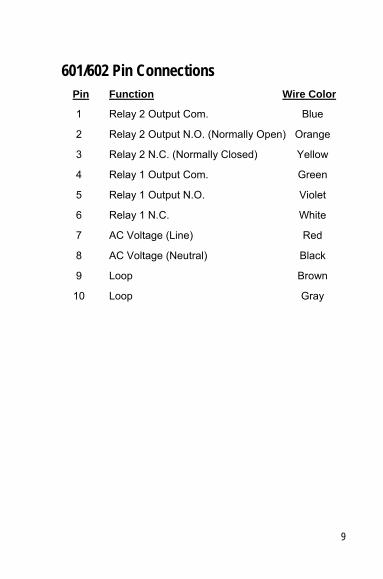
601/602 Pin Connections Pin Function Wire Color
1 Relay 2 Output Com. Blue
2 Relay 2 Output N.O. (Normally Open) Orange
3 Relay 2 N.C. (Normally Closed) Yellow
4 Relay 1 Output Com. Green
5 Relay 1 Output N.O. Violet
6 Relay 1 N.C. White
7 AC Voltage (Line) Red
8 AC Voltage (Neutral) Black
9 Loop Brown
10 Loop Gray

10 11

12
601/602 Specifications Inductance Range
18 to 1800 microHenries automatically tuned
Frequency Range
10 to 97 kHz One of four operating frequency ranges can be selected with switches 1 & 2 on the board-mounted DIP switch.
Temperature Range
-40°C to +85°C
Outputs
Both relays 1 and 2 are changeover relay contacts rated at 250VAC, 5A, 150W/600VA max.
Lightning and Transient Protection
Zener diode protection from over-voltage induced on loop and feeder leads. Flash over-protection from loop to earth. Protection exceeds NEMA specification.
Supply Power
120VAC or 24VAC
9
601/602 Pin Connections Pin Function Wire Color
1 Relay 2 Output Com. Blue
2 Relay 2 Output N.O. (Normally Open) Orange
3 Relay 2 N.C. (Normally Closed) Yellow
4 Relay 1 Output Com. Green
5 Relay 1 Output N.O. Violet
6 Relay 1 N.C. White
7 AC Voltage (Line) Red
8 AC Voltage (Neutral) Black
9 Loop Brown
10 Loop Gray

8
Testing the Loop A good loop is critical for reliable operation from your detec-tor. When installing your loop, take great care not to dam-age the insulation of the wire. Breaks in the insulation can cause the wire to act as a wick — pulling in moisture, cor-roding the wire itself, and causing erratic operation from the detector. Cross-link polyethylene is the most popular insula-tion and is strongly recommended (XHHW), in 16 or 18 gauge. If the lead-in is extremely long, increase the wire size. The insulation must be able to withstand wear and abrasion from the shifting of pavement, moisture, and at-tacks by solvents and oils, as well as able to withstand high-temperature sealants. Stranded wire is recommended over solid wire, because of its mechanical characteristics. Stranded wire is more likely to survive bending and stretch-ing than solid wire.
Megging a loop and lead-in should have an insulation resis-tance to earth greater than 20M�, measured at 500 Volts. One end of the loop goes to one lead from the meggar, and the other lead from the meggar goes to a good ground. The loop should also display a series resistance of less than 10� with a standard Ohm meter. If a problem with a loop is suspected, try swapping the detector with a known good detector and see if the problem follows the detector or the loop.
13
Specifications (continued) Reset
Reset is accomplished either by changing the sensitivity or by un-plugging the detector
Loop Fault Indications
If the 601/602 detects a loop fault (open loop, shorted loop, or greater than a 25% inductance change,) the bi-color LED will flash red at a 16 Hz rate. If the fault condition corrects itself, the bi-color LED will continue to flash until the detector is reset, but the detector will resume normal operation. When the detector is reset, it will resume normal operation within three seconds.
Presence Time
60 minutes, standard
Presence Time Options
8 minutes, 16 minutes, or permanent
Dimensions
3” high × 1.5” wide × 3.5” long (excluding connector)

14
Troubleshooting Q: The detector LED blinks red, and it won’t detect anything.
A: A blinking red LED is telling us there is a problem tuning the loop. An open loop, shorted loop, bad connection to the harness, loop wires twisted around the entire loop and not just the lead-in, or not enough turns in the loop are possible causes.
Q: The detector won’t let the door or gate down, it just reverses and goes back up
A: The loop has been installed too close to the door. A loop detector does not know the difference between a vehicle and a moving metal door or gate. If turning down the sensi-tivity does not help, consult the factory or move the loop farther away from the metal object, at least 4 feet away.
Q: The detector doesn’t detect trucks
The sensitivity is not high enough or the loop is too small to detect the generally higher metal chassis of a truck. Adjust the sensitivity or increase the size of the loop so that it can detect the truck. A loop can typically detect any metal that is less than 1/2 to 1/3 the distance of the smallest side of the loop.
Q: The detector is erratic
Detectors are generally very stable. If you see erratic behav-ior, check the loop for continuity and leakage to ground. Check for constant supply voltage. Check to see that the detector and operator are properly grounded. Check to see that the wiring harness is securely attached.
7
About the 601/602 • Small size: 4½”L × 3¼”W × 1”H (114 × 83 × 26 mm) • Failsafe or Failsecure outputs • Sensitivity boost • Eight selectable sensitivities • Easy to use DIP switch controls • Relay output mode selectable
⎯ Pulse on Entry ⎯ Pulse on Exit ⎯ Second Relay output ⎯ Loop fault output
• 120VAC or 24VAC input • Current and historical loop fault indicators • Compatible with existing equipment • Automatic tuning • Consistent presence time

6
Sensitivity Eight sensitivity settings are available using the 8-position rotary switch on the 601/602. 0 = OFF 7 = MAX 6 = 0.04% 7 = 0.02% 4 = 0.16% 5 = 0.08% 2 = 0.64% 3 = 0.32% 0 = OFF 1 = 1.28% The above sensitivities are for the detect threshold when a vehicle enters the loop. The detector has a SENSITIVITY BOOST facility whereby the drop sensitivity decreases to half its numerical initial value (except the 0.02 setting.)
Always operate the detector on the lowest sensitivity possi-ble while still detecting the desired vehicles. Construct the loop for your specific job. Remember the smallest side of the loop will determine how high off the ground you will be able to detect a vehicle. Your loop will have an effective field 1/2 to 2/3rds of the smallest side of the loop. Example: A 6’x6’ loop has a smallest side of 6’, therefore your detector can reliably see a vehicle at 3’ to 4’ above the loop wires. A 6’ x 3’ loop has a smallest side of 3’, so therefore you detec-tor will reliably see a vehicle 11/2’ to 2’ above the loop wires.
Also remember, your loop will sense metal off to the sides, although not from as far as directly above the loop. Do not install the loop too closely to any moving metal. The detec-tor does not know the difference between a vehicle and a metal door or gate. Keep your loop far enough away from any moving metal to avoid false detections, approximately 4’ at least.
15
Loop Installation Tips The loop consists of a 12 to 18 gauge stranded wire suitable for direct burial with low AC and DC resistance. The size of your loop will be determined by the width of the area in which you need detection, and the height of the vehicles you need to detect. If high-bed trucks will be detected, the loop should be no less than 6’ on a side (i.e. at least 6’×6’.)
Smaller loops are suitable for car or fork truck detection. The depth of the saw cut is typically 1¼” to 2”, and from ¼” to 3/8” wide. Cut the corners of the loop to 45° angles to avoid pulling loop wires around a 90° corner and risk dam-aging the wires. Do no push the loop wires into the saw-cut with a sharp object. Be sure to keep the loops a minimum of 2” above any rebar or wire mesh installed in the roadway.
The loop wire is wound to form a coil (usually 3 to 5 turns.) Ideally, there should be no splices in the loop. Or, in other words, attach your loop wire to the gray wire in the wiring harness, run the loop out to your saw-cut, go around the saw cut the recommended number of times, return the loop wire back to the detector. Twist the lead-in portion of the loop wires at least 5 to 7 twists per foot, and then connect the other end of the loop wire to the brown wire on the wir-ing harness. The lead-ins and loop should be made of one continuous piece of wire.
Important: Twist only the lead-in (the part of the loop wire that runs from the edge of the loop back to the detector.) Do not twist the wires in the loops themselves.

16
Loop Size
(ft) 1 Turn 2 Turns 3 Turns 4 Turns
4 × 4 7 20 44 78
4 × 6 8 25 56 100
4 × 10 12 36 81 144
4 × 15 17 50 112 199
4 × 20 21 64 143 253
4 × 25 26 78 174
4 × 30 30 91 204
4 × 35 35 105 235
4 × 40 39 119 266
4 × 45 44 132
4 × 50 49 146
4 × 55 53 160
4 × 60 58 174
4 × 65 62 187
4 × 70 67 201
4 × 75 71 215
4 × 80 76 228
4 × 85 81 242
4 × 90 85 256
4 × 95 90 270
Inductance(μH)*
4 × 100 94 283
4 Foot Loop Width
*optimum detection range is between 70μH and 250μH
5
Presence—Constant presence (detect) while metal is over the loop
Pulse on Exit—Momentary pulse when metal leaves the loop
Pulse on Entry—Momentary pulse when metal enters the loop

4
601/602 Definition of Outputs Presence means the relay will be energized the entire time a metal mass is within the field generated by the loops. The 601/602 has the ability to provide two outputs. Either relay can be set for presence or pulse. Relay 1 (pins 4 & 5, green and violet wires) can be set for presence using switch num-bers 3 & 4 on the board-mounted, 8 position, DIP switch. Set switch 3 to OFF and switch 4 to ON.
Pulse on Entry means that the relay will be energized as soon as a metal mass enters the field generated by the loop. Set switch 3 to OFF and switch 4 to OFF. This pulse will last 125mS.
Pulse on Exit means that the relay will be energized when a metal mass has left the loop. Set switch 3 to ON and switch 4 to OFF. The pulse will last 125mS.
Loop fault output means the relay will be energized if there is a current fault (open loop, shorted loop or greater than a 25% inductance change.)
SWITCHES 3 & 4 CONTROL OUTPUT MODE: OFF + ON = PRES. OFF + OFF = POE ON + OFF = POL ON + ON = FAULT
17
Loop Size
(ft) 1 Turn 2 Turns 3 Turns 4 Turns
6 × 4 8 25 56 100
6 × 6 10 31 70 124
6 × 10 14 43 96 171
6 × 15 19 58 129 229
6 × 20 24 72 161 286
6 × 25 29 87 194
6 × 30 34 101 226
6 × 35 38 116 259
6 × 40 43 130
6 × 45 48 145
6 × 50 53 159
6 × 55 58 173
6 × 60 63 188
6 × 65 67 202
6 × 70 72 217
6 × 75 77 231
6 × 80 82 246
6 × 85 87 260
6 × 90 91 275
6 × 95 96 289
Inductance(μH)*
6 × 100 101 303
6 Foot Loop Width
*optimum detection range is between 70μH and 250μH

18
Setup Details 1. Power is supplied to the unit on pins 7 & 8 (red and
black).
2. The most common hook-up is for using the presence relay, pins 4 & 5 (green and violet). The presence relay N.O. (normally open) pin 5 (violet) is connected to the Open, Close, Hold Open etc. (i.e. whichever function is to be performed.)
3. For a second presence or pulse output, relay 2, pins 1 & 2 (orange and blue,) are used. Relay 2 N.O. pin 2 (orange) is taken to the Open, Close, Hold Open etc. (whichever function is to be performed.) If a N.C. Nor-mally closed output is necessary, use pin 3 (yellow). Relay 2 common pin 1 (blue) is connected to the com-mon on the terminal strip of the operator.
4. The loop leads are on pins 9 & 10 (gray & brown). This is lead coming from the embedded loop in the ground. For proper operation, these leads must be twisted all the way to the detector.
Pin 1 Pin 10
3
Quick Setup 1. Verify the input voltage by the part number on the
silver label (located on the side of the oscillator cover.) 3NH = 120VAC 7NH = 24VAC
2. Make sure the harness is fitted correctly and snugly on the 10 pin molex connector.
3. With power applied, the bi-color LED should show green, indicating power is present. This same LED will show red during detection of a vehicle. (Red blinking indicates a loop fault. It will continue to blink until the detector is reset.)
4. Set sensitivity dial to medium (3 or 4).
5. Adjust the frequency to Low for a single loop (switch 1 and 2 to the ON position.) For multiple loop applica-tions, set each detector to a different frequency setting.

2
Copyright © 2009 Peek Traffic Corporation Printed in the USA. All rights reserved. Information furnished by Peek is believed to be accurate and reliable, however Peek does not warranty the accuracy, completeness, or fitness for use of any of the information furnished. No license is granted by implication or otherwise under any intellectual property. Peek reserves the right to alter any of the Company's products or published technical data relating thereto at any time without notice. No part of this publication may be reproduced, stored in a retrieval system, or transmitted in any form or via any electronic or mechanical means for any purpose other than the purchaser’s personal use without the expressed, written permission of Peek Corporation Peek Corporation 2906 Corporate Way Palmetto, FL 34221 USA Trademarks The Sarasota Model 601/602 and 625 Series Detectors are trademarks or registered trademarks of Peek Corporation in the USA and other countries. Microsoft and Windows are trademarks or registered trademarks of Microsoft Corporation. Other brands and their products are trademarks or registered trademarks of their respective holders and should be noted as such.
Content:: 99-370-2 Assy: 81-998-2
19

20
Sarasota Detectors 2906 Corporate Way Palmetto, FL 34221 Ph: (800) 245-7660 Fax: (941) 845-1504
Email: [email protected] Web: www.peektraffic.com
81-998-2 1
601/602 Series Inductive Loop Detector
Installation Guide
Sarasota Series Detectors