Embed Size (px)
Citation preview

INSTALLATION INSTRUCTIONS FOR SYMCOM'S MODEL 601 VOLTAGE MONITOR RELAY
BE SURE POWER IS DISCONNECTED PRIOR TO INSTALLATION!!FOLLOW NATIONAL, STATE AND LOCAL CODES!
READ THESE INSTRUCTIONS ENTIRELY BEFORE INSTALLATION.
CONNECTIONS
1. Using the four corner tabs OR the DIN rail mounting bracket, mount the Model 601 securely in thepanel. To use the DIN rail bracket, hook the top clip first, then apply downward pressure until the lower clip "clicks" onto the rail, then stop applying downward pressure.
2. Connect the three-phase power from the line side of the contactor to "L1", "L2" and "L3". First carefully strip and insert a #12 - #18 AWG wire into the top of the terminal marked L1 and tighten the screw on the front of the relay. Then, connect the other end of the wire to the line side of the contactor. Repeat these two steps for L2 and L3. (see Figure No. 1).
3. Connect the output relay to the circuitry to be controlled (see Figure No. 1). To control a motor, connect the normally open contact in series with the magnetic coil of the motor starter as shown.To sound an alarm, connect the normally closed contact in series with the alarm.
Figure No. 1: Typical Wiring Diagrams
2880 North Plaza Drive, Rapid City, SD 57702 • 800-843-8848

SUGGESTED SETTINGS (Consult the Motor Manufacturer for their recommendations.)
LV/HV- The recommended settings for "LV" (low voltage) and "HV" (high voltage) depend on many factors such as motor usage, motor size, environmental factors and tolerance of the motor. The motor manufacturer should be consulted for "HV" and "LV" settings. However, the NEMAMG1 standard recommends that "LV" and "HV" be set to no more than ±10% of the motor's nameplate voltage. The setting can be determined by multiplying the motor's nameplate voltage by the recommended percent over and under voltage. (eg., The motor nameplate voltage is 230 V, set "LV" to 0.9x230=207, set "HV" to 1.10x230=253) "LV" can not be set higher than "HV", so "HV" may have to be adjusted higher before the proper "LV" setting can be programmed.
VUB- "VUB" is the voltage unbalance trip point. The NEMA MG1 standard does not recommend operating a motor above a 1% voltage unbalance without derating the motor. Voltage unbalance is determined from the following formula:
% Voltage Unbalance = [(Maximum Deviation from the Average) / Average] x 100%
The NEMA MG1 standard also recommends against operating a motor above a 5% voltage unbalance under any circumstances. Therefore, a setting of "5" is a good place to start but SymCom recommends consulting the motor manufacturer for specific tolerances.
Note: A setting of "999" in this position will eliminate voltage unbalance protection. Single phase protection is still active for unbalances in excess of 15%.
LF- "LF" setting is the Low Frequency Trip threshold. The NEMA MG1 standard recommends against operating a motor on a supply with more than ±5% variation in frequency. On a 60Hz system, 60 x .95 = 57Hz.
5/03 - 2 -
PROGRAMMING
1. Select the feature to program by rotating the "MODE SELECT" switch to the desired position.
2. Push and hold the “RESET / PROGRAM” button.
3. Rotate the “DISPLAY / PROGRAM” adjustment to the desired setting of the feature as shown in the LED display.
4. Release the “RESET / PROGRAM” button. The Model 601 is programmed when the button is released.
5. Continue steps 1-4 until all features are programmed.

HF- "HF" setting is the High Frequency Trip threshold. Using the NEMA MG1 standard on a 60Hz system, "HF" = 60 x 1.05 = 63Hz.
TD1- "TD1" is the Trip Delay time for voltage and frequency faults. This includes voltage unbalance, low voltage, high voltage, low frequency and high frequency. A setting of 5-10 seconds is normally a good place to start for these types of faults.
TD2- "TD2" is the Trip Delay time for single-phasing faults. A setting of 2-4 seconds is a good place to start.
RD1- "RD1" is the rapid cycle timer. It will engage when the MotorSaver is first powered-up. An "RD1"setting of 20-30 seconds will generally protect the motor from rapid, successive power outages. A setting of 0 seconds will allow the motor to start immediately after power-up.
RD2- "RD2" is the restart delay after a fault occurs. This delay allows the motor to cool down after experiencing a fault. It is also known as a motor cool down timer. Your motor manufacturer should be contacted to determine this setting. Under normal circumstances, a setting of 300 seconds will give the motor enough time to cool down between faults.
#RF- "#RF" is the type of reset after a fault. A setting of "0" is manual reset and a setting of "A" is continuously automatic.
ADDR- "ADDR" is the address setting for RS485 communications. Available settings are from A01 - A99.You may ignore this setting if RS485 communications are not used.
1LFT, 2LFT, 3LFT, 4LFT- These positions are the last four faults stored in memory. Note: The motor will be shut down when accessing these positions. Also, the last fault may be displayed by pushing the "RESET" button at any time during normal operation.
MULTI-FUNCTION SYSTEM DISPLAY
The output display can show various system operating parameters:• L1-L2 Voltage • Average Voltage • L2-L3 Voltage• % Voltage Unbalance • L3-L1 Voltage • Line Frequency
When the "MODE SELECT" switch is in the "RUN" position, the LED will display one of the above operating parameters. To select or change the displayed parameter, turn the "DISPLAY / PROGRAM" adjustment to the desired position as shown on its label.
The multifunction display also announces system faults such as low voltage, high voltage, single phasing, voltage unbalance, and reverse phasing errors. Any time the "MODE SELECT" switch is in the "RUN" position, the "RESET/PROGRAM" button may be pushed to view the last fault which occurred. The table on page 4 shows the possible messages. To view the previous faults, rotate the "MODE SELECT" switch to the corresponding last fault. NOTE: Rotating the "MODE SELECT" switch out of the run position will de-energize the Model 601's contacts and shut down the motor.
- 3 - 5/03
5/03 - 4 -
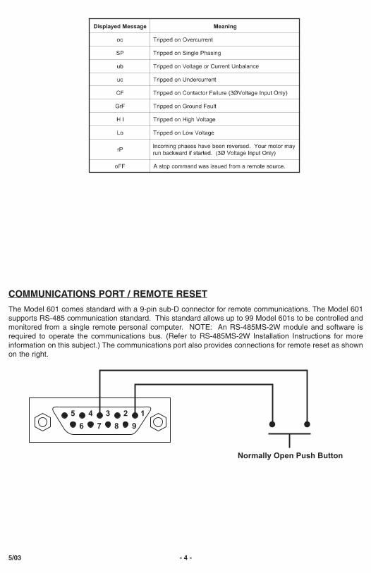
COMMUNICATIONS PORT / REMOTE RESET
The Model 601 comes standard with a 9-pin sub-D connector for remote communications. The Model 601supports RS-485 communication standard. This standard allows up to 99 Model 601s to be controlled andmonitored from a single remote personal computer. NOTE: An RS-485MS-2W module and software isrequired to operate the communications bus. (Refer to RS-485MS-2W Installation Instructions for moreinformation on this subject.) The communications port also provides connections for remote reset as shownon the right.
5 4 3 2
6 7 8 9
1
Normally Open Push Button

GNITOOHSELBUORT
MELBORP NOITULOS
setanretlayalpsiD.tratstonlliwtinuehT"MARGORP/YALPSID"ehthtiw"Pr"
.eulavretemaraphctiws
ehtfoowtynapaws,putratslaitiniehtsisihtfI.desahpesrevererastupniegatlovehTneebsahyalerehtfI.melborpehttcerrocot"3L"ro,"2L","1L"otdetcennocsdaelesahpehtkcehC.desahpesreverneebsahmetsysrewopeht,gninnurylsuoiverp
.senilrewopgnimocniehtfoecneuqes
setanretlayalpsiD.tratstonlliwtinuehThtiw"FL"ro"FH","oL","IH","Bu","PS"
hctiws"MARGORP/YALPSID"eht.eulavretemarap
"FH","VL","VH","BUV"ehtnidemmargorpstimilehtnihtiwtonsiegatlovgnimocniehTenilgnimocniehtdaerothctiws"MARGORP/YALPSID"ehttsujdA.sgnittes"FL"dna
otstimildemmargorpkcehcdnamelborprewopgnimocniehttcerroC.seulavegatlov.tcerrocerayehtyfirev
,"FH","FL","Bu","PS"setanretlayalpsiD".NUR"htiw"IH"ro"oL"
"2DR"nwodgnimitsidnayalpsidDELehtnonwohstluafehtnodeppirtsahyalerehT.gnitratsererofeb
,"Bu","PS"dilosagniwohssiyalpsiD".FH"ro"FL","oL","IH"
ehtfoesuacebderiuqersiteserlaunamdnanwohstluafehtnodeppirtsahtinuehT."FR#"nignittesdemmargorp
OPERATION
Once the relay has been programmed, turn the "MODE SELECT" switch to the "RUN" position. The LEDdisplay will flash "RUN" alternately with a number representing the parameter indicated by the "DISPLAY /PROGRAM" adjustment. After the period of time programmed into RD1, the output contacts will closeand the value of the parameter indicated by the "DISPLAY / PROGRAM" adjustment will appear on theLED display.
If a message other than those indicated above is shown on the LED display, see the TROUBLESHOOTING section to diagnose the problem.
If you need further assistance, call us at 1-800-843-8848...we'd be happy to help!!

NOTES: SymCom's Model 601 can be preprogrammed prior to installation by applying 120 VAC between the L1 and L2 terminals.* 575 Volt Model (MS601-575).** MS601-HVR.

Clearing Last Fault
The last fault stored can be cleared on the MotorSaver.
This procedure is outline as follows:
1. Rotate the Mode Select Switch to 4LFT .
2. Press and hold the Reset/Program Button. Adjust the Display/Program adjustment until cLr appears
on the display. Release the Reset/Program Button.
To verify the last fault was cleared, place the Mode Select switch in the Run position. Then press and
hold the Reset/Program Button, cLr should be on the display.
Tamper Guard
The PumpSaver can be protected from unauthorized program changes by locking in the setpoints.
This procedure is outlines as follows:
1. Rotate the Mode Select switch to 4LFT .
2. Rotate Display/Program adjustment fully clockwise.
3.Press and hold the Reset Button. Adjust the Display/Program adjustment until Loc appears in the display.
4. Release the Reset Button.
5. Turn Mode Select switch to run .
The program is now locked, but all settings can be viewed. The unit can be unlocked by following the
procedure above except step three. This step should say: Press and hold the Reset Button. Adjust the
Display/Program adjustment until unL appears in the display.

Model 601 Dimensions
2880 North Plaza Drive, Rapid City, SD 57702 • 800-843-8848