Embed Size (px)
Citation preview

Cascade is a Registered Trademark of Cascade Corporation
cascade�
Manual Number 6009757
C-SeriesFork Positioner
ERVICE MANUALS

i 6009757 Rev. 0
PageINTRODUCTION, Section 1
Introduction, 1.1 1Special Definitions, 1.2 1
INSTALLATION, Section 2Truck System Requirements, 2.1 2Recommended Hydraulic Supply Options, 2.2 3Fork Positioner Installation Procedure, 2.3 4
PERIOD MAINTENANCE, Section 3100-Hour Maintenance, 3.1 9500-Hour Maintenance, 3.2 91000-Hour Maintenance, 3.3 92000-Hour Maintenance, 3.4 9
TROUBLESHOOTING, Section 4General Procedures, 4.1 10
Truck System Requirements, 4.1-1 10Tools Required, 4.1-2 10Troubleshooting Chart, 4.1-3 10
Plumbing, 4.2 11Hosing Diagram,Fork Position Circuit, 4.2-1 11Hosing Diagram, Sideshift Circuit, 4.2-2, 4.2-3 12Hydraulic Circuit, 4.2-4, 4.2-5 14
Fork Position Function, 4.3 16Supply Circuit Test, 4.3-1 16Fork Circuit Test, 4.3-2 16Valve Test, 4.3-3 17Cylinder Test, 4.3-4 17
Sideshift Function, 4.4 18Supply Circuit Test, 4.4-1 18Sideshift Cylinder Test, 4.4-2 18Sideshifting Valve Test, 4.4-3 19
Electrical Circuit, 4.5 20
ONTENTSCSERVICE, Section 5
Fork Positioner Removal, 5.1 21Forks, Shafts, 5.2 22
Removal and Installation, 5.2-1 22Fork Inspection, 5.2-2 23Fork Bearing Service, 5.2-3 23Fork Carrier, 5.2-4 24
Valve, 5.3 25Valve Removal, Installation, 5.3-1 25Eliminating Regeneration Circuit, 5.3-2 25Valve Service, 5.3-3 26
Sideshift Cylinder, 5.4 27Cylinder Removal, Installation, 5.4-1 27Cylinder Disassembly, 5.4-2 28Cylinder Inspection, 5.4-3 28Cylinder Reassembly, 5.4-4 29
Fork Position Cylinders, 5.5 30Cylinder Removal, Installation, 5.5-1 30Cylinder Disassembly, 5.5-2 31Cylinder Inspection, 5.5-3 31Cylinder Reassembly, 5.5-4 32
Sideshifter Frame, 5.6 33Bearings, Anchor Plate Replacement, 5.6-1 33
Solenoid Valve, 5.7 34Coil Service, 5.7-1 34Valve Service, 5.7-2 34
SPECIFICATIONS, Section 6Specifications, 6.1 35
Hydraulics, 6.1-1 35Auxiliary Valve Functions, 6.1-2 35Truck Carriage, 6.1-3 35Torque Values, 6.1-4 36
Page
C-Series Fork Positioner

6009757 Rev. 0 1
I NTRODUCTION
1.1 IntroductionThis Manual provides the Installation Instructions, PeriodicMaintenance, Troubleshooting, Service and Specifica-tions for Cascade C-Series Fork Positioners.
In any communication about the Fork Positioner, refer tothe product I.D. number stamped on the nameplate asshown. If the nameplate is missing, the numbers can befound stamped on the back of the baseplate.
IMPORTANT: All hoses, tubes and fittings on C-SeriesFork Positioners are JIC.
NOTE: Specifications are shownin both U.S. and (Metric) units.
1.2 Special DefinitionsThe statements shown appear throughout this Manualwhere special emphasis is required. Read all WARNINGSand CAUTIONS before proceeding with any work.Statements labeled IMPORTANT and NOTE are providedas additional information of special significance or tomake the job easier.
CAUTION - A statement preceded by CAUTION isinformation that should be acted upon to preventmachine damage.
IMPORTANT - A statement preceded by IMPORTANT isinformation that possesses special significance.
NOTE - A statement preceded by NOTE is informationthat is handy to know and may make the job easier.
WARNING - A statement preceded byWARNING is information that should beacted upon to prevent bodily injury. AWARNING is always inside a ruled box.
221550
cascadeLIFT TRUCK ATTACHMENT
ATTACHMENT CAPACITY
SERIAL NUMBER
CATALOGNUMBER
ADDITIONALEQUIPMENT
ADDITIONALEQUIPMENT
ADDITIONALEQUIPMENT
WEIGHT LBS.
POUNDSAT
INCH LOAD CENTER
CAPACITY OF TRUCK AND ATTACHMENT COMBINATIONMAY BE LESS THAN ATTACHMENT CAPACITY SHOWNABOVE. CONSULT TRUCK NAMEPLATE.
RECOMMENDED SYSTEM PRESSURE – 2000 PSIMAXIMUM SYSTEM PRESSURE – 2300 PSI
cascade corporation�
�
c
55C-FPB-01A
FOR TECHNICAL ASSISTANCE, CONTACT800-227–2233PORTLAND, OREGON USA
FOR PARTS AND SERVICE MANUALS, CONTACT800-227–2233SPRINGFIELD, OHIO USA
FP0328.ill
S/N 221550
Nameplate

2 6009757 Rev 0
I NSTALLATION
2.1 Truck SystemRequirementsC-Series Fork Positioners will provide maximum operatingcapability when the following requirements are met.
WARNING: Rated capacity of the truck/attachment combination is a responsibility ofthe original truck manufacturer and may beless than that shown on the attachmentnameplate. Consult the truck nameplate.
GA0082.ill
Close Forks
SideshiftRight
TiltForward
Hoist Up
Auxiliary Valve FunctionsCheck for compliance with ITA (ISO) standards:
TiltBack
Hoist Down
Spread Forks
SideshiftLeft
GA0080.ill
CarriageClean and inspect carriage bars fordamage and smoothness. Repair anyprotruding welds or damaged notches.GA0028.ill
Carriage Mount Dimension (A) ITA (ISO)
Minimum Maximum
Class II 14.96 in. (380.0 mm) 15.00 in. (381.0 mm)Class III 18.68 in. (474.5 mm) 18.74 in. (476.0 mm)Class IV 23.44 in. (595.5 mm) 23.50 in. (597.0 mm)
Truck Relief Setting2000 psi (140 bar) Recommended2300 psi (160 bar) Maximum
Truck Flow Volume ➀
Min. ➁ Recommended Max. ➂
55C, 100C, 5 GPM 7 GPM 10 GPM120C, 150C (19 L/min.) (26 L/min.) (38 L/min.)
➀ Cascade C-Series Fork Positioners are compatible with SAE 10Wpetroleum base hydraulic fluid meeting Mil. Spec. MIL-0-5606 orMIL-0-2104B. Use of synthetic or aqueous base hydraulic fluid isnot recommended. If fire resistant hydraulic fluid is required,special seals must be used. Contact Cascade.
➁ Flow less than recommended will result in slow and unequal forkmovement.
➂ Flow greater than maximum can result in excessive heating,reduced system performance and reduced hydraulic system life.
A
6009757 Rev. 0 3
I NSTALLATION
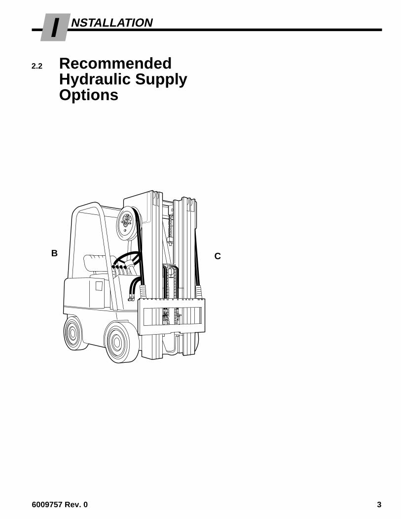
2.2 RecommendedHydraulic SupplyOptions
CB
GA0033.ill
A
Non-SideshiftingA Mast Single Internal Reeving
ORB RH THINLINE� 2-Port Hose Reel Group
SideshiftingA Mast Double Internal Reeving
ORA and B Mast Single Internal Reeving and
RH THINLINE� 2-Port Hose ReelGroup
ORB and C RH and LH THINLINE� 2-Port Hose
Reel Groups
Solenoid AdaptionA and B Mast Single Internal Reeving and
RH Cable Reel GroupOR
B RH 6-N-1 Cable/Hose Reel Group
C-Series Fork Positioners can be operated with any of thehydraulic supply arrangements shown below. Refer toCascade Hose & Cable Reel Selection Guide, Part No.212199, to select the correct hose reel for the mast andtruck. Hose and fitting requirements are as follows:
• All hoses and fittings for the fork-positioning andsideshifting (if equipped) functions should be at leastNo. 6 with 9/32 in. (7 mm) minimum I.D.

4 6009757 Rev 0
I NSTALLATION
2.3 Installation ProcedureFollow the steps shown to install the Fork Positioner on thetruck. Read and understand all WARNING and CAUTIONstatements. If you don't understand a procedure, ask yoursupervisor, or call the nearest Cascade Service Depart-ment for assistance.
2 Unlock Quick-Change lower mounting hooks (if equipped)A Remove pin and drop hooks into unlocked position.
B Re-install pin in lower hole.
1
ca
sc
ad
e®
C-675514-1
CL0097.ill
A
Pin
LH lowerHook
NOTE: Guides can be reversed toreduce hook-to-carriage clearance(See lower hook installation, Step 6).Guide
5/8-in. (16 mm)offset on topprovides max.clearance.
B
FP0202.ill
CBolt-OnLowerHooks
B
Wood Blocking
Attach overhead hoistA Remove banding.
B Attach hoist to top of backrest asshown and lift Attachment into verticalposition on pallet. Use wood blockingas required to stabilize Attachment.
C Remove bolt-on lower mounting hooks(if equipped).
WARNING: Make sure overheadhoist has a rated capacity of atleast 2000 lbs. (910 kg.)
Tighten Capscrews:Class II / III Mounting – 165 ft.-lbs. (225 Nm)Class IV Mounting – 190 ft.-lbs. (255 Nm)
B

6009757 Rev. 0 5
I NSTALLATION
3
FP0213.ill
ca
sc
ad
e®
C-675514-1
SS0141.ill
Mount Fork Positioner on truckA Center truck behind Attachment.
B Hang Attachment onto truck carriage, or raisecarriage into upper hooks (see inset).
C Engage upper mounting hooks or sideshiftingfull-length upper hook. IMPORTANT: Ifsideshifter equipped, assure upper bearingsare installed properly and centering tabengages center notch on truck carriage bar.
QUICK-DISCONNECT TYPE(optional)
Tighten Capscrews:Class II, III Mounting – 165 ft.-lbs. (225 Nm)Class IV Mounting – 190 ft.-lbs. (255 Nm)
4 Install or engage lower hooks
Inspect hooks forexcessive clearance.(Reverse guides toreduce clearance –see Step 2.)
Slide hook upto engagebar, installpin in lockedposition.(upper hole.)
SS0139.ill
ADJUST
SS0140.ill
LowerCarriageBar
LowerCarriageBar
3/16 in.(4.8 mm)max.
C
ITA Class II – 0.32–0.36 in. (8–9 mm)ITA Class III – 0.39–0.43 in. (10–11 mm)ITA Class IV – 0.47–0.51 in. (12–13 mm)
ITA Class II – 0.60–0.66 in. (15–17 mm)ITA Class III – 0.72–0.78 in. (18–20 mm)ITA Class IV – 0.72–0.78 in. (18–20 mm)
CenterNotch
TruckCarriage
Back (Driver's) View
B
SD0023.ill
Sideshifting full-lengthupper hook shown
BOLT-ON TYPE
Tap tight into position.If sideshifter, back off1 notch andcheck clearance:3/32 in. (2.4 mm) min.3/16 in. (4.8 mm) max.
FP0366.ill
B
Sideshifter UpperBearings (if equipped)
C

6 6009757 Rev 0
I NSTALLATION
Prepare hosesA Determine hose lengths required for
hydraulic supply configuration of truck.
B Cut hoses to length and install end fittingsor quick-disconnect kits.
5
INTERNAL HOSE REEVING – 100C, 120C, 150C
Back (Driver's) Views
FP0367.ill
FP0200.ill
Close ForksSpread Forks
FP0221.ill
Close ForksSpread Forks
SSR SSL
Spread ForksClose Forks
HOSE REELS – 55C Frame Sideshifting
HOSE REELS – 100C, 120C, 150C
HOSE REELS – 55C Internal Sideshifting
FP0349.ill
SSRSSL
SSR SSL
Close Forks
Spread Forks
SSR SSL
SOLENOID – 6-N-1 CABLE/HOSE REEL
FP0199.ill
SSL / Spread Forks(TANK port)
SSR / Close Forks(PRESSURE port)
6009757 Rev. 0 7
I NSTALLATION
Solenoid Coil
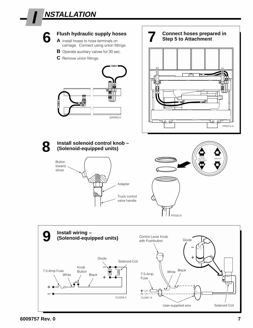
Connect hoses prepared inStep 5 to Attachment7
9 Install wiring –(Solenoid-equipped units)
SIDESHIFTPRESS
BUTTON TO POSITION
FP0320.ill
Buttontowarddriver
Truck controlvalve handle
Adapter
8 Install solenoid control knob –(Solenoid-equipped units)
CL0258.ill CL0257.ill
Solenoid CoilUser-supplied wire
7.5-AmpFuse
White Black7.5-Amp FuseWhite Black
Solenoid Coil
Diode
Diode
KnobButton
Control Lever Knobwith Pushbutton
FP0214.ill
6 Flush hydraulic supply hosesA Install hoses to hose terminals on
carriage. Connect using union fittings.
B Operate auxiliary valves for 30 sec.
C Remove union fittings.
GA0092.ill
8 6009757 Rev 0
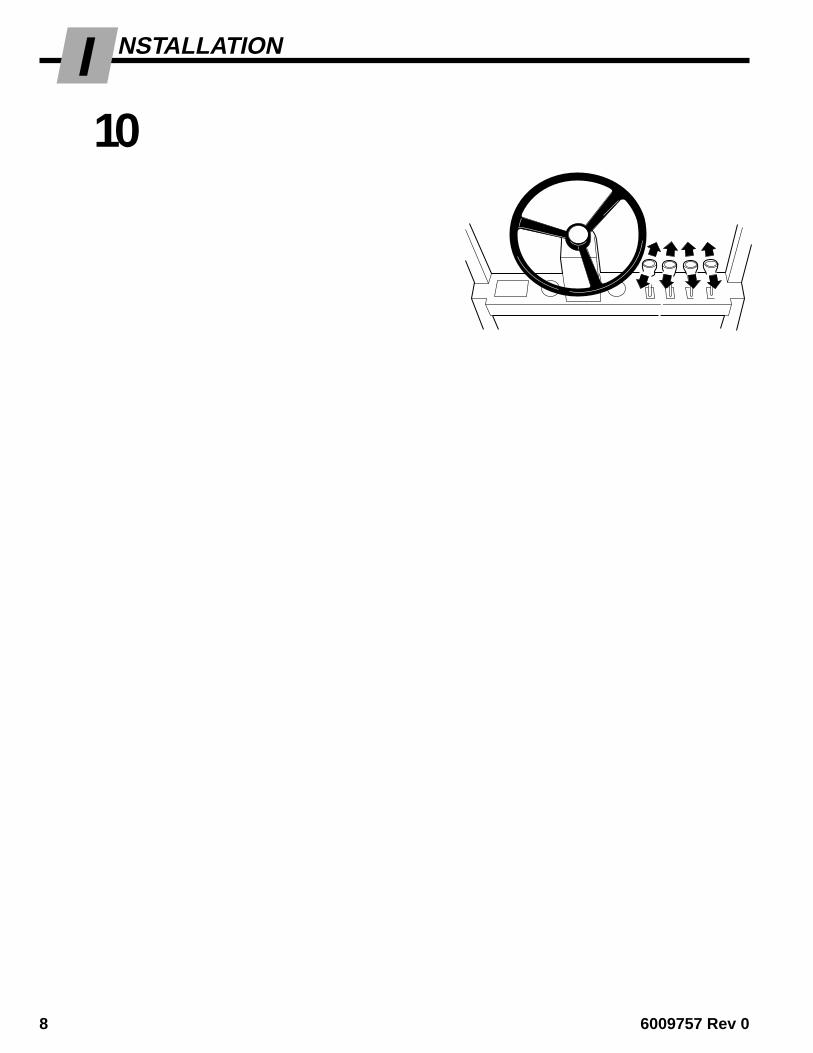
I10
NSTALLATION
B D
CA
GA0005.ill
Tilt backHoist up
Hoist down Tilt forward
Cycle Fork Positioner functions
SIDESHIFTING WITHSOLENOID VALVE
A Sideshift Left
A Spread Forks(press knob button)
B Sideshift Right
B Close Forks(press knob button)
NON-SIDESHIFTING
A Spread Forks
B Close Forks
• Spread forks and close forks several times.Sideshift (if equipped) left and right. Checkfor smoothness and equal movement.
• Check for operation in accordance with ITA(ISO) standards.
• Check for leaks at fittings, valve, cylinders.
AB
ABB A
C
C
D
D AB
A
AB
B
SIDESHIFTING
A Sideshift Left
B Sideshift Right
C Spread Forks
D Close Forks
Adjust forks for equal movement(if required)
NOTE: Attachment is Factory-adjusted for equalfork movement when operated at recommendedpressure and flow rate.
A Locate cylinder 'T' fittings with flow restrictoradjustment. Loosen jam nuts and screwboth flow restrictors in until they bottom.Screw each restrictor out (CCW) three turns.
B Spread forks fully, then close. Look forunequal fork movement.
C On faster fork (one that bottoms first), screwflow restrictor in (CW) 1/2-turn.
D Repeat Steps B and C until fork movementis equal. Tighten jam nuts.
11
Front View
FP0194.ill
Flow RestrictorAdjustment Screw
AUXILIARY VALVE FUNCTIONSCheck for compliance with ITA (ISO)standards:
A
ForkPositioningCylinder
Jam Nut
'T' fitting
C
FP0204.illFP0204.ill
FP0204.ill

6009757 Rev. 0 9
ROUBLESHOOTINGT ERIODIC MAINTENANCEP
3.1 100-HourMaintenanceEvery time the lift truck is serviced or every 100 hours oftruck operation, whichever comes first, complete thefollowing maintenance procedures on the Fork Positioner:
• Check for loose or missing bolts, worn or damagedhoses and hydraulic leaks.
3.2 500-HourMaintenanceAfter each 500 hours of truck operation, in addition to the100-hour maintenance, perform the following procedures:
• Tighten lower mounting hook capscrews:
Class II, III Mounting – 165 ft.-lbs. (225 Nm)Class IV Mounting – 190 ft.-lbs. (255 Nm)
• Apply chassis grease to fork bearing grease fittings.
• Apply chassis grease to fork cylinder rod anchors.
• Apply chassis grease to sideshifter (if equipped) upperbearing grease fittings and lower flat bearings.
3.3 1000-HourMaintenanceAfter each 1000 hours of truck operation, in addition to the100 and 500-hour maintenance, perform the followingprocedures:
• Inspect forks for wear. Cascade Fork Safety Kit3014162 is available for this procedure.
• Inspect fork bearings for wear and replace if necessary.
• Inspect fork cylinder rod anchors for wear and replaceif necessary.
• Inspect sideshifter (if equipped) upper and lowerbearings for wear and replace if necessary.
3.4 2000-HourMaintenanceAfter each 2000 hours of truck operation, in addition to the100, 500 and 1000-hour maintenance, perform the follow-ing procedures:
• Replace fork bearings (see Section 5.2-3).
• Replace upper and lower sideshifter bearings (ifequipped). See Section 5.6.
WARNING: After completing any serviceprocedure, always test each functionthrough five complete cycles. First testwith no load, then test with a load tomake sure the attachment operatescorrectly before returning it to the job.
Back (Driver's) View
Fork BearingGrease Fittings (4)
Lower Mounting HookCapscrews (4)
Cylinder RodAnchors (2)
ForkBearings (4)
Sideshifter Upper BearingGrease Fittings (2)(sideshift to expose fittings)
SideshifterLower Bearings (2)
FP0201.ill
FP0215.ill
Front View

10 6009757 Rev. 0
ROUBLESHOOTINGT
Pressure Gauge Kit 671212PressureGauge*
No. 6 and No. 8JIC Swivel Tee
No. 4-6 Pipe/JIC*
No. 6-6 Hose*
Flow Meter Kit 671477
GA0013.ill
(2) No. 6-8 JIC Reducer
Flow Meter
No. 4, No. 6*and No. 8JIC/O-Ring
No. 6-8 JICReducer
(2) No. 8-12 JIC/O-Ring
4.1 General Procedures4.1-1 Truck System Requirements
• Truck hydraulic pressure should be within the rangeshown in Specifications, Section 6.1. PRESSURE TOTHE FORK POSITIONER MUST NOT EXCEED 2300psi (160 bar).
• Truck hydraulic flow should be within the range shownin Specifications, Section 6.1.
• Hydraulic fluid supplied to the Fork Positioner mustmeet the requirements shown in Specifications,Section 6.1.
4.1-2 Tools RequiredIn addition to a normal selection of hand tools, thefollowing are required:
• 20 GPM (75 L/min) inline flow meter.(Cascade Flow Meter Kit, part no. 671477.)
• 3000 psi (200 bar) pressure gauge.(Cascade Pressure Gauge Kit, part no. 671212.)
• Assorted fittings, drain hoses and quick-disconnectsas required.
GA0014.ill
WARNING: Before servicing anyhydraulic component, relieve pressure inthe Attachment system. Turn the truck offand move the truck auxiliary control leverseveral times in both directions.
After completing any service procedure, always testthe Attachment through several cycles. First testempty to bleed any air trapped in the system to thetruck tank. Then test with a load to assure that theAttachment operates correctly before returning to thejob. Stay clear of the load while testing. Do not raisethe load more than 4 in. (10 cm) off the floor whiletesting.
AC0127.ill
Diagnostic Quick-Disconnects
Male Straight ThreadO-Ring Coupler:No. 4 (Part No. 212282)*No. 5 (Part No. 210378)No. 6 (Part No. 678592)
Female JIC ThreadQD Coupler:No. 4 (Part No. 210385)*No. 6 (Part No. 678591)
* included in Diagnostics Kit 394382.
4.1-3 Troubleshooting ChartDetermine All The Facts – It is important to gather allthe facts about the problem before beginning any serviceprocedures. The first step is to talk to the equipmentoperator. Ask for a complete description of the malfunc-tion. Guidelines below and on the following pages canthen be used as a starting point to begin troubleshooting.
Fork Positioning Circuit• Forks have uneven travel.
• Forks move slowly.
• Forks will not move.
To correct these problems, see Section 4.3.
NOTE: Some Fork Positioners have a regenerativehydraulic circuit that causes the forks to open at a fasterspeed than when closing. This is a normal function.
Sideshift Circuit• Forks sideshift left and right at different speeds.
• Forks will not sideshift.
To correct these problems, see Section 4.4.

6009757 Rev. 0 11
ROUBLESHOOTINGT4.2 Plumbing4.2-1 Hosing Diagram,
Fork Position Circuit
CLOSE FORKS SPREAD FORKS
Pressure:
Return:
FP0322.ill
OPENPort
CLOSEPort
Hose Reel orInternal Reeving
Truck AuxiliaryValves
Fork PositionCylinders (2)
AttachmentValve
Hose/Cable Reelor Internal Reeving
Truck Auxiliary Valve (with pushbutton)
To Fork PositionCylinders
Solenoid Valve(Energized)
CLOSEPort
SOLENOID ADAPTION
OPENPort
SideshiftCylinder
SideshiftCylinder P Port
T Port
12 6009757 Rev. 0
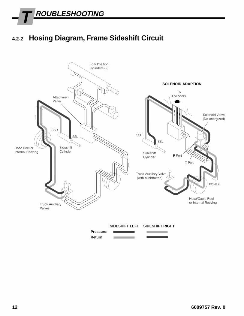
ROUBLESHOOTINGT4.2-2 Hosing Diagram, Frame Sideshift Circuit
SIDESHIFT LEFT SIDESHIFT RIGHT
Pressure:
Return:
FP0323.ill
SSL SSR
SSL
SSR
Hose Reel orInternal Reeving
Truck AuxiliaryValves
Fork PositionCylinders (2)
Hose/Cable Reelor Internal Reeving
Truck Auxiliary Valve (with pushbutton)
ToCylinders
Solenoid Valve(De-energized)
SOLENOID ADAPTION
AttachmentValve
SideshiftCylinder Sideshift
Cylinder P Port
T Port

6009757 Rev. 0 13
ROUBLESHOOTINGT4.2-3 Hosing Diagram, Integral Sideshift Circuit
SIDESHIFT LEFT SIDESHIFT RIGHT
Pressure:
Return:
Slave:
FP0352.ill
SSL
SSR
SSL
SSR
Hose Reel orInternal Reeving
Truck AuxiliaryValves
Fork PositionCylinders (2)
Hose/Cable Reelor Internal Reeving
Truck Auxiliary Valve (with pushbutton)
ToCylinders
Solenoid Valve(De-energized)
SOLENOID ADAPTION
AttachmentValve
P Port
T Port

14 6009757 Rev. 0
ROUBLESHOOTINGT4.2-4 Hydraulic Circuit –
Fork Positioner, Frame Sideshifter
CL1046.ill
Solenoid Adaption
Truck Auxiliary Valve(SIDESHIFT/POSITION)
Solenoid Valve
2-Port Hose/Cable Reel
TANKPort
Fork Position Cylinders (2)
FP0324.ill
Forks CloseCheck ValveCartridge
Truck Relief ValveTruck Pump
2-Port Hose Reels (2) orInternal Hose Reeving
TruckAuxiliaryValve(FORKPOSITION)
Truck Tank
RegenerationValve
Test Port G
TruckAuxiliaryValve(SIDESHIFT)
PRESSUREPort
AttachmentValve
CLOSEOPEN
FlowRestrictorFittings (2)
Sideshift Cylinder(if equipped)
RestrictorWasher

6009757 Rev. 0 15
ROUBLESHOOTINGT4.2-5 Hydraulic Circuit –
Fork Positioner with Integral Sideshifting
CL1046.ill
Solenoid Adaption
Truck Auxiliary Valve(SIDESHIFT/POSITION)
Solenoid Valve
2-Port Hose/Cable Reel
TANKPort
Fork Position/Sideshift Cylinders (2)
FP0353.ill
CloseCheckValveCartridge
Truck Relief ValveTruck Pump
2-Port Hose Reels (2) orInternal Hose Reeving
TruckAuxiliaryValve(FORKPOSITION)
Truck Tank
RegenerationValve
TruckAuxiliaryValve(SIDESHIFT)
PRESSUREPort
AttachmentValve
CLOSE
OPEN
Flow RestrictorFittings (2)
SSL
SSR
Sideshift CheckValve Cartridges (2)
Test Port G

16 6009757 Rev. 0
ROUBLESHOOTINGT4.3 Fork Position
FunctionThere are six potential problems that could affect the FORKPOSITION function:
• Damaged or bent frame.
• Incorrect load handling. Refer to Operator’s Guide forsuggested procedures.
• Incorrect hydraulic pressure or flow from the lift truck.
• External leaks.
• Defective solenoid coil or valve (if equipped).
• Worn or defective cartridge valves or cylinder seals.
4.3-1 Supply Circuit Test1 Check the pressure supplied by the truck at the carriage
hose terminal. Pressure must be within the range shownin Specifications, Section 6.1. PRESSURE TO THEFORK POSITIONER MUST NOT EXCEED 2300 PSI (160 bar).
2 Check the flow volume at the carriage hose terminal.Flow must be within the range shown in Specifications,Section 6.1.
3 Close the forks fully, holding the lever in the CLOSEposition for a few seconds. Release the lever and checkfor external leaks at fittings, hoses, valve and manifold.
4.3-2 Fork Circuit Test1 Press the solenoid button (if equipped) and listen for a
'click' at the solenoid valve. If no sound is heard, firstcheck the fuse, wiring and coil (see Section 4.5). Assurethat the valve is not jammed (see Section 5.7).
IMPORTANT: Solenoid-operated valves must beplumbed so that the solenoid is energized during theFORK POSITION function.
2 Position the forks to mid-stroke. Turn the truck off andconnect a 3000 psi (200 bar) pressure gauge to the 'G'test port on the back of the main valve.
3 Start the truck and close the forks fully, holding the leverin the CLOSE position for a few seconds.
4 Release the lever and watch the pressure gauge:
• If the pressure drop is less than 150 psi (10 bar)initially, and additional drop does not exceed 25 psi(1.7 bar) per minute, the problem is not hydraulic (seeSection 4.3).
• If the pressure drop is more than 150 psi (10 bar)initially, and additional drop exceeds 25 psi (1.7 bar)per minute, Turn the truck off and proceed to ValveTest, Section 4.3-3.
WARNING: Before removing hydrauliclines or components, relieve pressure in theAttachment hydraulic system. Turn thetruck off and move the auxiliary controllever several times in both directions.
FP0326.ill
FP0325.ill
Flow Meter 2
3Back (Driver's) View
Pressure Gaugeon test port 'G' 2
6009757 Rev. 0 17
ROUBLESHOOTINGT
FP0335.ill
FP0336.ill
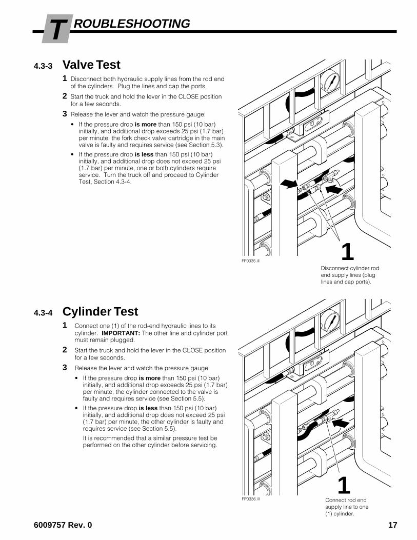
4.3-3 Valve Test1 Disconnect both hydraulic supply lines from the rod end
of the cylinders. Plug the lines and cap the ports.
2 Start the truck and hold the lever in the CLOSE positionfor a few seconds.
3 Release the lever and watch the pressure gauge:
• If the pressure drop is more than 150 psi (10 bar)initially, and additional drop exceeds 25 psi (1.7 bar)per minute, the fork check valve cartridge in the mainvalve is faulty and requires service (see Section 5.3).
• If the pressure drop is less than 150 psi (10 bar)initially, and additional drop does not exceed 25 psi(1.7 bar) per minute, one or both cylinders requireservice. Turn the truck off and proceed to CylinderTest, Section 4.3-4.
4.3-4 Cylinder Test1 Connect one (1) of the rod-end hydraulic lines to its
cylinder. IMPORTANT: The other line and cylinder portmust remain plugged.
2 Start the truck and hold the lever in the CLOSE positionfor a few seconds.
3 Release the lever and watch the pressure gauge:
• If the pressure drop is more than 150 psi (10 bar)initially, and additional drop exceeds 25 psi (1.7 bar)per minute, the cylinder connected to the valve isfaulty and requires service (see Section 5.5).
• If the pressure drop is less than 150 psi (10 bar)initially, and additional drop does not exceed 25 psi(1.7 bar) per minute, the other cylinder is faulty andrequires service (see Section 5.5).
It is recommended that a similar pressure test beperformed on the other cylinder before servicing.
1
1
Disconnect cylinder rodend supply lines (pluglines and cap ports).
Connect rod endsupply line to one(1) cylinder.
18 6009757 Rev. 0
ROUBLESHOOTINGT
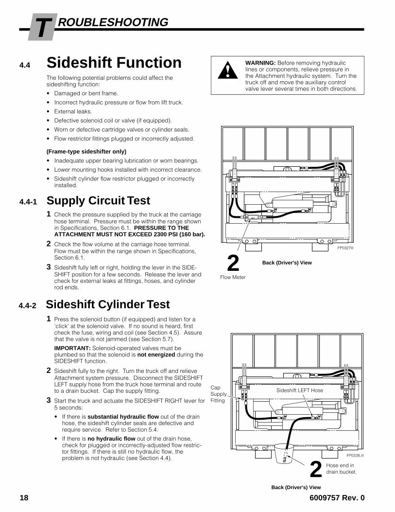
Hose end indrain bucket.2
4.4 Sideshift FunctionThe following potential problems could affect thesideshifting function:
• Damaged or bent frame.
• Incorrect hydraulic pressure or flow from lift truck.
• External leaks.
• Defective solenoid coil or valve (if equipped).
• Worn or defective cartridge valves or cylinder seals.
• Flow restrictor fittings plugged or incorrectly adjusted.
(Frame-type sideshifter only)
• Inadequate upper bearing lubrication or worn bearings.
• Lower mounting hooks installed with incorrect clearance.
• Sideshift cylinder flow restrictor plugged or incorrectlyinstalled.
4.4-1 Supply Circuit Test1 Check the pressure supplied by the truck at the carriage
hose terminal. Pressure must be within the range shownin Specifications, Section 6.1. PRESSURE TO THEATTACHMENT MUST NOT EXCEED 2300 PSI (160 bar).
2 Check the flow volume at the carriage hose terminal.Flow must be within the range shown in Specifications,Section 6.1.
3 Sideshift fully left or right, holding the lever in the SIDE-SHIFT position for a few seconds. Release the lever andcheck for external leaks at fittings, hoses, and cylinderrod ends.
1 Press the solenoid button (if equipped) and listen for a'click' at the solenoid valve. If no sound is heard, firstcheck the fuse, wiring and coil (see Section 4.5). Assurethat the valve is not jammed (see Section 5.7).
IMPORTANT: Solenoid-operated valves must beplumbed so that the solenoid is not energized during theSIDESHIFT function.
2 Sideshift fully to the right. Turn the truck off and relieveAttachment system pressure. Disconnect the SIDESHIFTLEFT supply hose from the truck hose terminal and routeto a drain bucket. Cap the supply fitting.
3 Start the truck and actuate the SIDESHIFT RIGHT lever for5 seconds:
• If there is substantial hydraulic flow out of the drainhose, the sideshift cylinder seals are defective andrequire service. Refer to Section 5.4.
• If there is no hydraulic flow out of the drain hose,check for plugged or incorrectly-adjusted flow restric-tor fittings. If there is still no hydraulic flow, theproblem is not hydraulic (see Section 4.4).
WARNING: Before removing hydrauliclines or components, relieve pressure inthe Attachment hydraulic system. Turn thetruck off and move the auxiliary controlvalve lever several times in both directions.
FP0327ill
Flow Meter
2 Back (Driver's) View
FP0338.ill
Sideshift LEFT Hose
Back (Driver's) View
CapSupplyFitting
4.4-2 Sideshift Cylinder Test
6009757 Rev. 0 19
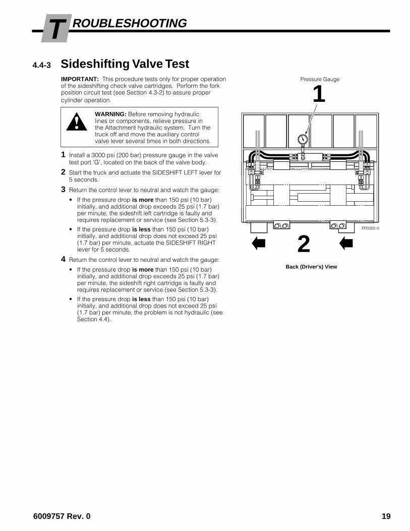
ROUBLESHOOTINGTIMPORTANT: This procedure tests only for proper operationof the sideshifting check valve cartridges. Perform the forkposition circuit test (see Section 4.3-2) to assure propercylinder operation.
1 Install a 3000 psi (200 bar) pressure gauge in the valvetest port 'G', located on the back of the valve body.
2 Start the truck and actuate the SIDESHIFT LEFT lever for5 seconds.
3 Return the control lever to neutral and watch the gauge:
• If the pressure drop is more than 150 psi (10 bar)initially, and additional drop exceeds 25 psi (1.7 bar)per minute, the sideshift left cartridge is faulty andrequires replacement or service (see Section 5.3-3).
• If the pressure drop is less than 150 psi (10 bar)initially, and additional drop does not exceed 25 psi(1.7 bar) per minute, actuate the SIDESHIFT RIGHTlever for 5 seconds.
4 Return the control lever to neutral and watch the gauge:
• If the pressure drop is more than 150 psi (10 bar)initially, and additional drop exceeds 25 psi (1.7 bar)per minute, the sideshift right cartridge is faulty andrequires replacement or service (see Section 5.3-3).
• If the pressure drop is less than 150 psi (10 bar)initially, and additional drop does not exceed 25 psi(1.7 bar) per minute, the problem is not hydraulic (seeSection 4.4).
Pressure Gauge
1
Back (Driver's) View
4.4-3 Sideshifting Valve Test
WARNING: Before removing hydrauliclines or components, relieve pressure inthe Attachment hydraulic system. Turn thetruck off and move the auxiliary controlvalve lever several times in both directions.
FP0350.ill
2

20 6009757 Rev. 0
ROUBLESHOOTINGT4.5 Electrical Circuit
(Solenoid-equipped Clamps)Use the electrical schematic and diagram shown andfollow the steps below:
1 Check the control knob circuit fuse. Replace ifnecessary.
2 Check for loose electrical connections at the truckignition switch, control knob button, solenoid coilterminals and diode.
3 Remove the diode from the solenoid coil terminal. Testwith an ohmmeter for high resistance in one directionand no resistance in the other direction. If there is noresistance in both directions, replace the diode.
NOTE: When replacing the diode, the banded (+) endmust be connected to the coil and wiring as shown.
4 Disconnect the electrical leads from the solenoid coilterminals. Use a voltmeter to determine if voltage ispresent at the electrical leads when the button isdepressed.
• If there is no current to the solenoid, troubleshootthe electrical circuit for shorts.
• If there is current to the solenoid, test for coilcontinuity.
5 Test for coil continuity by placing an ohmmeter testlead on each solenoid coil terminal (ohmmeter on Rx1scale).
• If there is an ohmmeter reading, the coil is good.
• If the coil is good, but the solenoid does not 'click'when the control knob button is depressed, thesolenoid cartridge may be jammed. Refer toSection 5.7.
• If there is no ohmmeter reading, the coil is defectiveand should be replaced. Refer to Section 5.7.
Solenoid Coil
CL0258.ill CL0257.ill
Solenoid CoilUser-supplied wire
7.5-AmpFuse
White Black7.5-Amp FuseWhite Black
Solenoid Coil
Diode
Diode
KnobButton
Control Lever Knobwith Pushbutton

6009757 Rev. 0 21
ERVICES
FP0329.ill
5.1 Fork PositionerRemoval1 Position the forks to the width of the frame.
2 Disconnect and plug the hydraulic supply hoses to thefork position cylinders and sideshifting cylinder (ifequipped). Tag hoses for reassembly.
3 Disconnect the lower hooks:
Quick-Change Hooks – Remove the locking pins anddrop the hooks into the unlocked position. Replace thepins in the lower holes. For reassembly, remove thepins and slide the hooks up to the locked position.Replace the pins in the upper holes.
Bolt-On Hooks – Remove the capscrews and mountinghooks. For reassembly, tap hooks tight into position fornon-sideshifting frame. If sideshifting frame, back off 1notch and check clearance: 3/32 in. (2.4 mm) min.,3/16 in. (4.8 mm) max. Tighten capscrews as follows:
Class II/III Mounting – 165 ft.-lbs. (225 Nm).Class IV Mounting – 190 ft.-lbs. (255 Nm).
4 Lower the Fork Positioner onto a pallet. Tilt the mastforward and lower the carriage to disengage the upperhook and anchor plate from the carriage.
5 For Fork Positioner installation, reverse the aboveprocedures. Refer to Section 2.3 for complete installa-tion information.
WARNING: Before removing hydrauliclines or hoses, relieve pressure in theAttachment hydraulic system. Turn thetruck off and move the auxiliary controllever several times in both directions.
FP0198.ill
ca
sc
ad
e¨
C-675514-1
RC0367.ill
RC0368.ill
ADJUST
43 QUICK-CHANGE LOWER HOOKS BOLT-ON LOWER HOOKS
Guide
Left Hook
Locking Pin(Unlocked Position)
Carriage Bar
Left Hook
SSL
OpenClose
Back (driver's) View
SSR
2

22 6009757 Rev. 0
ERVICES5.2 Forks, Shafts5.2-1 Removal and Installation
The following procedures can be performed with the ForkPositioner mounted on the truck.
1 Close the Forks to midrange. Lower forks to rest lightlyon a pallet or wood blocking.
2 Disconnect the spherical rod end nut that fastens thecylinder rod to the fork lug. For reassembly, assemblethe parts as shown. Tighten the rod end nut to 160 ft.-lbs. (220 Nm). NOTE: Spherical nut tightens againsthex washer, providing a loose operating clearance forthe anchor joint. Lubricate with chassis grease.
3 Retract the cylinders fully to disengage the rod endsfrom the fork lugs.
WARNING: Make sure forks are properlysupported by a pallet or wood blocking beforedisengaging from bearing shafts. Keep handsand feet clear from under forks.
FP0346.ill
4 Remove the backrest (or retainer plates if equipped).For reassembly, tighten the capscrews to 75 ft.-lbs.(100 Nm).
5 Slide the fork shafts out of the frame, disengaging theforks from the shafts.
6 For reassembly, reverse the above procedures with thefollowing exceptions:
• Inspect fork shafts for wear or bending damage.Replace shafts if necessary.
• After reassembly, lubricate fork bearings withchassis grease.
FP0354.ill
Hex washer (beveledside faces fork lug)
CylinderRod End
Fork Lug Cotter Pin
Rod End Nut,Locking Cap
ForkShafts (2)5
2
Backrest4
Hex Washer
RetainerPlates
NOTE: Usedonly whenthere is nobackrest.

6009757 Rev. 0 23
ERVICES
5.2-3 Fork Bearing Service
1 Remove the forks as described in Section 5.2-1.
2 Remove the snap rings that retain the bearing in thebearing boss. Remove the bearings.
3 For reassembly, reverse the above procedures withthe following exceptions:
• Install a new bearing in each bearing boss.
• Inspect the forks for damage or wear (see Section5.2-2).
• After reassembly, lubricate fork bearings withchassis grease.
FP0334.ill
Grease Fitting
Fork
Bearing
SnapRings (2)
5.2-2 Fork Inspection• Inspect the fork blade and tip for wear or damage.
NOTE: Cascade Fork Safety Kit 3014162 is availablefor this procedure and contains wear calipers, inspec-tion sheets and safety poster.
• Inspect the fork bearings for wear. Replace thebearings if necessary (see Section 5.2-3).
• Inspect the fork bearing boss and cylinder rod anchorlug for cracked welds or other damage. Replace thefork if necessary.
CAUTION: Repairing cracked welds must be ap-proved by Cascade. Contact Cascade Service forapproval and recommended welding procedures.
2
FP0368.ill
Bearing Boss,Bearings
Blade
Tip
Shank
CylinderRod AnchorLug
3

24 6009757 Rev. 0
ERVICES5.2-4 Fork Carrier
ITA FORK CARRIER
1 Inspect the ITA Fork Carriers for sideplate damage,spacer strip damage, or worn bearings. Replacedamaged parts as required.
If the carrier bearings are worn, remove the fork carriersas described in Section 5.2-1. Replace the carrierbearings as described in Section 5.2-3.
2 Inspect the bearing bosses and cylinder rod anchorlugs for cracked welds for other damage. Replace thefork carrier if required.
CAUTION: Repairing cracked welds must be ap-proved by Cascade. Contact Cascade Service forapproval and recommended welding procedures.
FP0369.ill
FP0355.ill
ITA FORK CARRIER
BOLT-ON FORK
Bearings (2)
Sideplates (2)
Spacer Strips (2)
Bearings (2)
Carrier
Positioning Lug
Bearing Boss
Positioning Lug
Snap Rings (2)
Fork
MountingCapscrews
Shims
BOLT-ON FORK CARRIER
1 Inspect the bearing bosses for cracked welds or wornbearings.
If the carrier bearings are worn, remove the fork carriersas described in Section 5.2-1. Replace the carrierbearings as described in Section 5.2-3.
2 Remove the fork capscrews. A torque multiplier isrequired to remove and tighten the larger capscrews.
3 For reassembly, reverse the above procedures with thefollowing exceptions:
• Lubricate the capscrews and tighten to the torquevalue indicated in the Table below. IMPORTANT:Use of new capscrews is recommended. Seeappropriate Cascade Parts Manual to order, orassure replacement capscrews are SAE Grade 8 orMetric/ISO 10.9.
Unit Capscrew Torque Values
55C 190-220 ft.-lbs. (257–298 Nm)
100C 280–320 ft.-lbs. (380–434 Nm)
120/150C 680–720 ft.-lbs. (922-976 Nm)
2
2
1
1 Bearing Boss
6009757 Rev 0 25
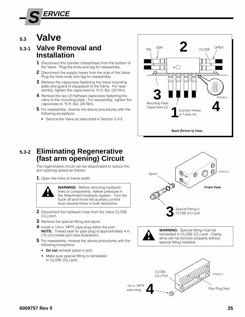
ERVICES5.3 Valve5.3-1 Valve Removal and
Installation1 Disconnect the cylinder tubes/hoses from the bottom of
the Valve. Plug the ends and tag for reassembly.
2 Disconnect the supply hoses from the side of the Valve.Plug the hose ends and tag for reassembly.
3 Remove the capscrews fastening the Valve mountingplate and guard (if equipped) to the frame. For reas-sembly, tighten the capscrews to 15 ft.-lbs. (20 Nm).
4 Remove the two (2) flathead capscrews fastening thevalve to the mounting plate. For reassembly, tighten thecapscrews to 15 ft.-lbs. (20 Nm).
5 For reassembly, reverse the above procedures with thefollowing exceptions:
• Service the Valve as described in Section 5.3-3.
5.3-2 Eliminating Regenerative(fast arm opening) CircuitThe regenerative circuit can be deactivated to reduce thearm opening speed as follows:
1 Open the forks to frame width.
2 Disconnect the hydraulic hose from the Valve CLOSE(CL) port.
3 Remove the special fitting and spool.
4 Install a 1/4-in. NPTF pipe plug within the port.NOTE: Thread seat for pipe plug is approximately 4 in.(10 cm) inside port (see illustration).
5 For reassembly, reverse the above procedures with thefollowing exceptions:
• Do not reinstall spool in port.
• Make sure special fitting is reinstalledin CLOSE (CL) port.
WARNING: Before removing hydrauliclines or components, relieve pressure inthe Attachment hydraulic system. Turn thetruck off and move the auxiliary controllever several times in both directions.
FP0331.ill
CL
OP
FP0332.ill
1/4 in. NPTFpipe plug 4 Pipe Plug Seat
G
FP0330.ill
2
1
WARNING: Special fitting must bereinstalled in CLOSE (CL) port. Clamparms will not function properly withoutspecial fitting installed.
Back (Driver's) View
3Mounting PlateCapscrews (2)
3 Special Fitting inCLOSE (CL) port
Spool
Cylinder Hosesor Tubes (4)
OPEN
4
CLOSE
Front View
CLOSE(CL) Port
SSRSSL

26 6009757 Rev. 0
ERVICES5.3-3 Valve Service
IMPORTANT: Service the Valve in a clean work area.
1 Remove the Valve from the Fork Positioner as described inSection 5.3-1.
2 Remove the CLOSE check valve cartridge. For reassem-bly, tighten cartridge to 50 ft.-lbs. (65 Nm).
3 Remove the sideshift check valve cartridges (if equipped).For reassembly, tighten cartridges to 50 ft.-lbs. (65 Nm).
4 Remove the special fitting and spool.
5 Remove the remaining plugs and fittings.
6 Remove the O-rings and back-up rings from the cartridgevalves, fittings and plugs.
7 Clean all parts with cleaning solvent or kerosene.
8 For reassembly, reverse the above procedures with thefollowing exceptions:
• Replace O-rings and back-up rings on cartridges andfittings as shown below.
• Lubricate cartridge, fittings and plugs with petroleumjelly prior to installation.
OP
CL
OP
CL
FP0333.ill
Special Fittingand Spool inCLOSE (CL) port
CLOSE CheckValve Cartridge 2
FP0337.ill
CLOSE CheckValve Cartridge
O-rings (4)
Back-up rings (6)
4RegenerationElimination Plug(if used)
O-rings,Back-UpRings
Sideshift CheckValve Cartridges
Valve Body
Spool
NON-SIDESHIFTING VALVE
SIDESHIFTING VALVE(unloaded-fork sideshifting)
3Sideshift CheckValve Cartridges (2)
8
FP0348.ill
O-rings (3)
Back-up rings (3)
CLOSE CheckValve Cartridge

6009757 Rev 0 27
ERVICES
5.4-1 Removal and InstallationNOTE: The following procedures can be performed withthe Fork Positioner mounted on the truck.
1 Disconnect the hoses from the cylinder ports. Tag thehoses for reassembly
2 Remove the clevis pins from the cylinder ends andremove the cylinder from the sideshifting frame.
3 For reassembly, reverse the above procedures with thefollowing exceptions:
• Service the cylinder as described in Section 5.4-2.
• Operate the sideshifter through several full cycles toclear the system of any entrapped air. Checkfittings and hoses for leaks.
5.4 Sideshift Cylinder
FP0359.ill
FP0360.ill
1WARNING: Before disconnectinghydraulic lines, relieve pressure in theAttachment hydraulic system. Turn thetruck off and move the auxiliary controllevers several times in both directions.
Back (Driver's) Views
55C FRAME SIDESHIFTING FORK POSITIONER
100C, 120C, 150C FRAME SIDESHIFTINGFORK POSITIONER
2 ClevisPins (2)
ClevisPins (2)
SSLSSR
SSLSSR 1
2

28 6009757 Rev. 0
ERVICES5.4-2 Cylinder Disassembly
1 Clamp the cylinder in a soft-jawed vise at the extremehead end only. Do not clamp on the shell.
2 Pull the cylinder rod to the fully extended position.Remove the spiral snap ring from the retainer.
3 Tap the retainer into the shell approximately 2 in. (50mm). Remove the circular retaining ring by prying itout of its groove on the opposite side from the splitends. CAUTION: Do not scratch the cylinder bore.
Service Tool Kit 674424 includes two double-edgedbrass tools that make seal and retaining ring removaleasy and won't damage the cylinder components withdents or scratches.
4 Remove the rod/piston assembly from the cylinder.
5 To remove the piston, clamp the rod assembly in a viseon the clevis end as shown. CAUTION: Do not clampon the cylinder rod sealing surface.
6 Remove the piston nut and remove the piston from thecylinder rod.
7 Place the piston or retainer in a soft-jawed vise toremove the seals. Pry the seals or O-rings out with abrass seal removal tool (Cascade Part No. 674424)and cut the seals to remove them. CAUTION: Do notscratch the seal grooves.
5.4-3 Cylinder Inspection• Inspect the rod, piston and retainer for nicks or burrs.
Minor nicks or burrs may be removed with 400-gritemery cloth. If they cannot be removed, replace theparts.
• Inspect the cylinder bore and remove any minor nicksor burrs with a butterfly. If they cannot be removed,replace the part. NOTE: Minor nicks are those that willnot pass hydraulic fluid under pressure.
• Inspect the outside of the shell for any deformities orcuts that could impair performance or cause leaksunder pressure. If necessary, replace the part.
SS0332.ill
PistonShell
Piston Nut
RodFlow Restrictor(head end only)
SS0088.ill
SS0059.ill
7
1
SS0061.ill
5SS0336.ill
2
SpiralSnap Ring
Retainer
Piston
4
Retainer
3
CircularRetainingRing
6009757 Rev 0 29
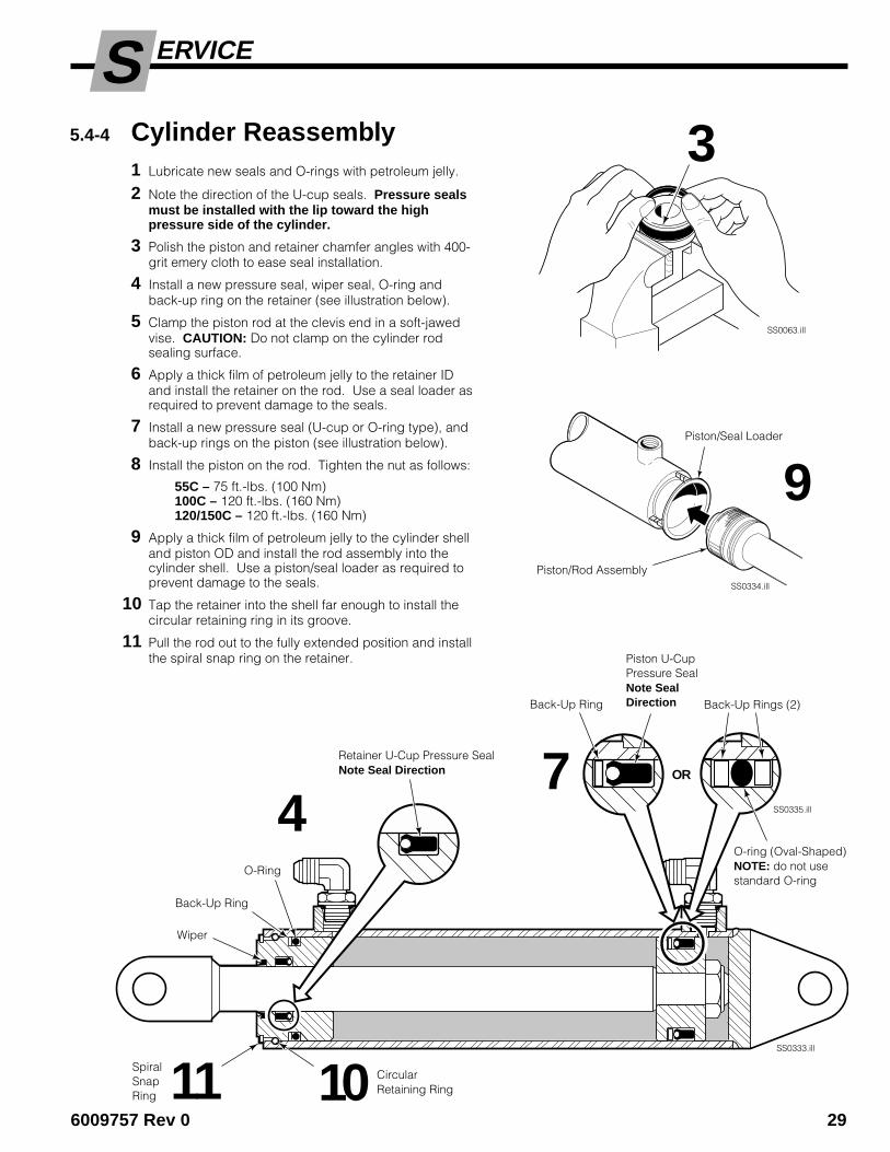
ERVICES5.4-4 Cylinder Reassembly
1 Lubricate new seals and O-rings with petroleum jelly.
2 Note the direction of the U-cup seals. Pressure sealsmust be installed with the lip toward the highpressure side of the cylinder.
3 Polish the piston and retainer chamfer angles with 400-grit emery cloth to ease seal installation.
4 Install a new pressure seal, wiper seal, O-ring andback-up ring on the retainer (see illustration below).
5 Clamp the piston rod at the clevis end in a soft-jawedvise. CAUTION: Do not clamp on the cylinder rodsealing surface.
6 Apply a thick film of petroleum jelly to the retainer IDand install the retainer on the rod. Use a seal loader asrequired to prevent damage to the seals.
7 Install a new pressure seal (U-cup or O-ring type), andback-up rings on the piston (see illustration below).
8 Install the piston on the rod. Tighten the nut as follows:
55C – 75 ft.-lbs. (100 Nm)100C – 120 ft.-lbs. (160 Nm)120/150C – 120 ft.-lbs. (160 Nm)
9 Apply a thick film of petroleum jelly to the cylinder shelland piston OD and install the rod assembly into thecylinder shell. Use a piston/seal loader as required toprevent damage to the seals.
10 Tap the retainer into the shell far enough to install thecircular retaining ring in its groove.
11 Pull the rod out to the fully extended position and installthe spiral snap ring on the retainer.
SS0333.ill
SS0334.ill
SS0063.ill
3
SS0335.ill
Back-Up Rings (2)
11SpiralSnapRing
O-ring (Oval-Shaped)NOTE: do not usestandard O-ring
4
Wiper
OR
Back-Up Ring
Retainer U-Cup Pressure SealNote Seal Direction
Piston U-CupPressure SealNote SealDirection
Back-Up Ring
O-Ring
Piston/Seal Loader
Piston/Rod Assembly
9
10 CircularRetaining Ring
7

30 6009757 Rev. 0
ERVICES
5.5-1 Removal and InstallationNOTE: The following procedures can be performed withthe Fork Positioner mounted on the truck.
1 Remove the backrest to provide access to the cylinderhead end anchors. For reassembly, tighten thecapscrews to 75 ft.-lbs. (100 Nm).
2 Position the forks to midrange and disconnect thecylinder rod ends from the forks by removing the cotterpin, locking cap and spherical nut.
3 Retract the cylinder rods until they disengage from thefork lugs.
4 Slide the disconnected forks to maximum frame widthto provide room to remove the cylinders.
5 Disconnect the hydraulic lines from the cylinder to beremoved. Plug the lines and cap the cylinder ports.Tag lines for reassembly.
6 Disconnect the cylinder head end from the frame byremoving the cotter pin, locking cap and spherical nut.Lift the cylinder away from the frame. During reassem-bly, assure that dowel pins are in place on the cylinderhead end.
7 For reassembly, reverse the above procedures with thefollowing exceptions:
• Service cylinder as described in Section 5.5-2.
• Lubricate threads and spherical nuts with grease.
• Install hex beveled washer on cylinder rod end.NOTE: Make sure beveled side faces lug as shown.
• Tighten spherical nuts to 160 ft.-lbs. (220 Nm).NOTE: Nut tightens against hex washer,providing a loose operating clearance.Lubricate anchor joints with chassis grease.
• Install locking caps using new cotter pins.
WARNING: After completing this serviceprocedure, test the Fork Positioner throughfive complete cycles. First test empty, then
test with a load to make sure the Attachment oper-ates correctly before returning it to the job.
CL0458.ill
Hex washer (beveledside toward fork lug)
CylinderRod End
Fork Lug Cotter Pin
Spherical Nut,Locking Cap
7
5.5 Fork Position Cylinders
WARNING: Before disconnecting hydrau-lic lines, relieve pressure in the Attachmenthydraulic system. Turn the truck off andmove the auxiliary control levers severaltimes in both directions.
FP0362.ill
2
5
6
1
4
6009757 Rev 0 31
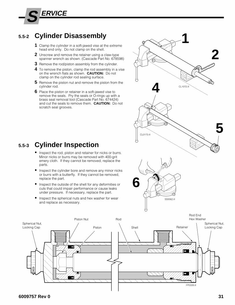
ERVICES5.5-2 Cylinder Disassembly
1 Clamp the cylinder in a soft-jawed vise at the extremehead end only. Do not clamp on the shell.
2 Unscrew and remove the retainer using a claw-typespanner wrench as shown. (Cascade Part No. 678598)
3 Remove the rod/piston assembly from the cylinder.
4 To remove the piston, clamp the rod assembly in a viseon the wrench flats as shown. CAUTION: Do notclamp on the cylinder rod sealing surface.
5 Remove the piston nut and remove the piston from thecylinder rod.
6 Place the piston or retainer in a soft-jawed vise toremove the seals. Pry the seals or O-rings up with abrass seal removal tool (Cascade Part No. 674424)and cut the seals to remove them. CAUTION: Do notscratch seal grooves.
5.5-3 Cylinder Inspection• Inspect the rod, piston and retainer for nicks or burrs.
Minor nicks or burrs may be removed with 400-gritemery cloth. If they cannot be removed, replace theparts.
• Inspect the cylinder bore and remove any minor nicksor burrs with a butterfly. If they cannot be removed,replace the part.
• Inspect the outside of the shell for any deformities orcuts that could impair performance or cause leaksunder pressure. If necessary, replace the part.
• Inspect the spherical nuts and hex washer for wearand replace as necessary.
FP0339.ill
Piston Retainer
Rod EndHex Washer
Shell
Piston Nut RodSpherical Nut,Locking Cap
Spherical Nut,Locking Cap
SS0062.ill
CL1072.ill
6
1
CL0173.ill
2
4
5
32 6009757 Rev. 0
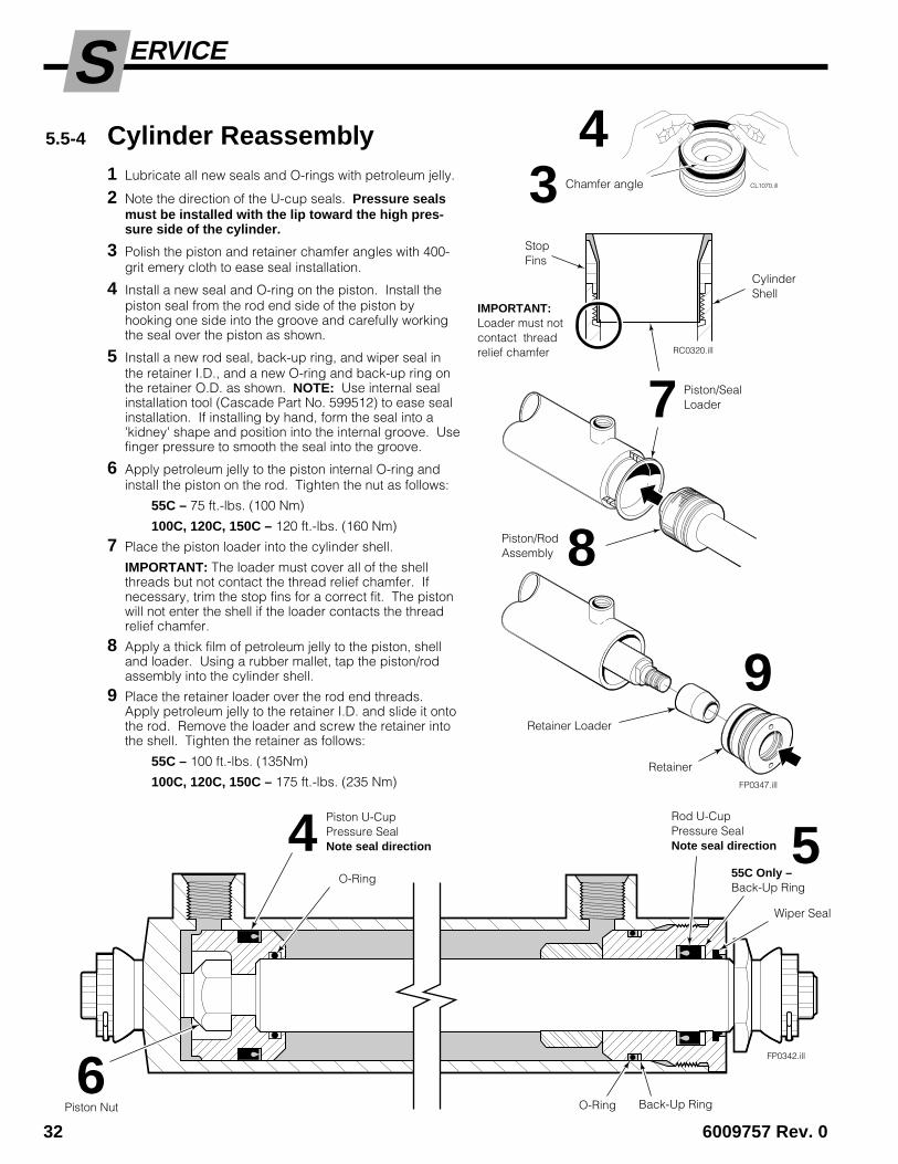
ERVICES5.5-4 Cylinder Reassembly
1 Lubricate all new seals and O-rings with petroleum jelly.
2 Note the direction of the U-cup seals. Pressure sealsmust be installed with the lip toward the high pres-sure side of the cylinder.
3 Polish the piston and retainer chamfer angles with 400-grit emery cloth to ease seal installation.
4 Install a new seal and O-ring on the piston. Install thepiston seal from the rod end side of the piston byhooking one side into the groove and carefully workingthe seal over the piston as shown.
5 Install a new rod seal, back-up ring, and wiper seal inthe retainer I.D., and a new O-ring and back-up ring onthe retainer O.D. as shown. NOTE: Use internal sealinstallation tool (Cascade Part No. 599512) to ease sealinstallation. If installing by hand, form the seal into a'kidney' shape and position into the internal groove. Usefinger pressure to smooth the seal into the groove.
6 Apply petroleum jelly to the piston internal O-ring andinstall the piston on the rod. Tighten the nut as follows:
55C – 75 ft.-lbs. (100 Nm)
100C, 120C, 150C – 120 ft.-lbs. (160 Nm)
7 Place the piston loader into the cylinder shell.
IMPORTANT: The loader must cover all of the shellthreads but not contact the thread relief chamfer. Ifnecessary, trim the stop fins for a correct fit. The pistonwill not enter the shell if the loader contacts the threadrelief chamfer.
8 Apply a thick film of petroleum jelly to the piston, shelland loader. Using a rubber mallet, tap the piston/rodassembly into the cylinder shell.
9 Place the retainer loader over the rod end threads.Apply petroleum jelly to the retainer I.D. and slide it ontothe rod. Remove the loader and screw the retainer intothe shell. Tighten the retainer as follows:
55C – 100 ft.-lbs. (135Nm)
100C, 120C, 150C – 175 ft.-lbs. (235 Nm)
RC0320.ill
StopFins
CylinderShell
FP0342.ill
Rod U-CupPressure SealNote seal direction
Piston U-CupPressure SealNote seal direction
Wiper Seal
O-Ring
IMPORTANT:Loader must notcontact threadrelief chamfer
O-Ring Back-Up Ring
54
CL1070.ill
4Chamfer angle3
55C Only –Back-Up Ring
6
FP0347.ill
7 Piston/SealLoader
8Piston/RodAssembly
9Retainer Loader
Retainer
Piston Nut

6009757 Rev 0 33
ERVICES
4 Replace the upper bearings. All bearings should bereplaced if any bearing is worn to less than 1/16 in. (1.5mm) thick on the back surface as shown.
CAUTION: During reassembly, assure that the upperbearings are installed correctly in the anchor plate asshown. Lower hook clearance will not be correct if theupper bearings are not installed correctly.
5 Replace the lower bearings. All bearings should bereplaced if any bearing is worn to less than 1/16 in. (1.5mm) exposed thickness.
6 Pry the lower bearings out of the bearing pockets. Cleanthe bearing pockets with solvent. NOTE: Lowerbearings should be a tight press fit into the framepockets.
7 For reassembly, reverse the above procedures.
55C FORK POSITIONER 100C, 120C, 150C FORK POSITIONER
5.6 Sideshifting Frame5.6-1 Bearings and Anchor Plate
ReplacementNOTE: The Fork Positioner must be removed from thetruck to accomplish the following procedures.
1 Remove the Fork Positioner from the truck as describedin Section 5.1.
2 Remove the sideshifter anchor plate and bearings.Clean the upper hook and truck carriage with solvent.
3 Inspect the truck carriage for damaged notches. Repairas required. If replacing bearings only, inspect thecentering tab on the anchor plate to assure that it is notdamaged or broken off.
Back (Driver's) View
FP0372.ill
FP0371.ill
Minimum exposed bearingthickness 1/16 in. (1.6 mm).
5Front View
LowerSideshiftBearings
24Upper Sideshift
Bearings
Anchor Plate
Upper BearingArrangement
6
1/16 in.(1.6 mm)Minimum.
F

34 6009757 Rev. 0
ERVICES
RC0204.ill
1 2
3
Coil
Solenoid ValveAssembly
5.7 Solenoid Valve5.7-1 Coil Service
1 Disconnect the wires and diode from the coil terminals.
2 Loosen the end cover capscrews. Remove the endcover and coil.
3 Install the new coil and end cover. Assure that theterminals are positioned correctly.
4 For reassembly, reverse the above procedures exceptas follows:
• Refer to the electrical schematic in Section 4.5 forcorrect wire and diode installation.
5.7-2 Valve Service• Check the plunger within the valve body for freedom of
movement. If jammed or damaged, replace thesolenoid valve as a complete assembly.

6009757 Rev. 0 35
PECIFICATIONSS
GA0091.ill
6.1 Specifications6.1-1 Hydraulics
6.1-3 Truck Carriage
GA0090.ill
TiltBack
GA0082.ill
CloseForks
SideshiftRight
TiltForward
Hoist Up
Hoist Down
SpreadForks
SideshiftLeft
GA0028.ill
A
Carriage Mount Dimension (A) ITA (ISO)
Minimum Maximum
Class II 14.94 in. (380.0 mm) 15.00 in. (381.0 mm)Class III 18.68 in. (474.5 mm) 18.74 in. (476.0 mm)Class IV 23.44 in. (595.5 mm) 23.50 in. (597.0 mm)
6.1-2 Auxiliary Valve FunctionsCheck for compliancewith ITA (ISO) standards:
Truck Relief Setting2000 psi (140 bar) Recommended2300 psi (160 bar) Maximum
Truck Flow Volume ➀
Min. ➁ Recommended Max. ➂
55C, 100C 5 GPM 7 GPM 10 GPM120C, 150C (19 L/min.) (26 L/min.) (38 L/min.)
➀ Cascade C-Series Fork Positioners are compatible with SAE10W petroleum base hydraulic fluid meeting Mil. Spec. MIL-0-5606 or MIL-0-2104B. Use of synthetic or aqueous basehydraulic fluid is not recommended. If fire resistant hydraulicfluid is required, special seals must be used. Contact Cascade.
➁ Flow less than recommended will result in slow and unequal forkmovement.
➂ Flow greater than maximum can result in excessive heating,reduced system performance and reduced hydraulic system life.
Hoses and FittingsAll hoses and fittings for the fork-positioning and sideshift(if equipped) functions should be at least No. 6 with 9/32in. minimum I.D.

36 6009757 Rev. 0
PECIFICATIONSS6.1-4 Torque Values
Fastener torque values for C-Series Fork Positioners areshown in the table below in both U.S. and Metric units. Alltorque values are also called out in each specific serviceprocedure section throughout the Manual.
Ref. Fastener Size Ft.-lbs. Nm
1 Valve mounting plate-to-frame (2) M-10 15 20
2 Valve-to-mounting plate (2) M-10 15 20
3 Quick-Change lower hook (4), CL II / III M-16 165 225CL IV M-16 190 255
4 Bolt-on lower hook (4), CL II / III M-16 165 225CL IV M-16 190 255
5 Sideshifter lower hook (4), CLII /III M-16 165 225CL IV M-16 190 255
6 Backrest/Retainer Plate-to-frame (8) M-12 75 100
7 Cylinder anchor nut (4) 3/4 UNF 160 220
8 Cylinder piston-to-rod nut (2) 5/8 UNF 75 1007/8 UNF 120 160
9 Bolt-on fork- 55C 1/2 UNC (M16) 200 280to-carrier 100C/ 5/8 UNC (M20) 300 405
120C/150C 3/4 UNC (M24) 700 950
7
6FP0365.ill
FP0351.ill
34
1
5
8
2
Piston Nut
CylinderAnchorNuts (4)
Back View
55C
100C, 120C, 150C
FP0455.ill
9 Bolt-On ForkCapscrews
Backrest/Retainer PlateCapscrews


c7579006 rebmuN traP2002-11002 noitaroproC edacsaC
Do you have questions you need answered right now? Call your nearest Cascade Service Department.Visit us online at www.cascorp.com
AMERICASCascade CorporationU.S. Headquarters2201 NE 201stFairview, OR 97024-9718Tel: 800-CASCADE (227-2233)Fax: 888-329-8207
Cascade Canada Inc.5570 Timberlea Blvd.Mississauga, OntarioCanada L4W-4M6Tel: 905-629-7777Fax: 905-629-7785
Cascade do BrasilRua João Guerra, 134Macuco, Santos - SPBrasil 11015-130Tel: 55-13-2105-8800Fax: 55-13-2105-8899
EUROPE-AFRICACascade Italia S.R.L.European HeadquartersVia Dell’Artigianato 137050 Vago di Lavagno (VR) ItalyTel: 39-045-8989111Fax: 39-045-8989160
Cascade (Africa) Pty. Ltd.PO Box 625, Isando 160060A Steel RoadSparton, Kempton ParkSouth AfricaTel: 27-11-975-9240Fax: 27-11-394-1147
ASIA-PACIFICCascade Japan Ltd.2-23, 2-Chome,Kukuchi NishimachiAmagasaki, Hyogo Japan, 661-0978Tel: 81-6-6420-9771Fax: 81-6-6420-9777
Cascade Korea121B 9L Namdong Ind. Complex, 691-8 Gojan-DongNamdong-KuInchon, KoreaTel: +82-32-821-2051Fax: +82-32-821-2055
Cascade-XiamenNo. 668 Yangguang Rd. Xinyang Industrial ZoneHaicang, Xiamen CityFujian ProvinceP.R. China 361026Tel: 86-592-651-2500Fax: 86-592-651-2571
Cascade India Material Handling Private LimitedNo 34, Global Trade Centre 1/1 Rambaugh ColonyLal Bahadur Shastri Road, Navi Peth, Pune 411 030(Maharashtra) IndiaPhone: +91 020 2432 5490Fax: +91 020 2433 0881
Cascade Australia Pty. Ltd.1445 Ipswich RoadRocklea, QLD 4107AustraliaTel: 1-800-227-223Fax: +61 7 3373-7333
Cascade New Zealand15 Ra Ora DriveEast Tamaki, AucklandNew ZealandTel: +64-9-273-9136Fax: +64-9-273-9137
Sunstream IndustriesPte. Ltd.18 Tuas South Street 5Singapore 637796Tel: +65-6795-7555Fax: +65-6863-1368