Embed Size (px)
Citation preview
7/23/2019 600 Series Cld Ops Manual 1213
http://slidepdf.com/reader/full/600-series-cld-ops-manual-1213 1/116
S E R I E S
6 CLD
LD
LD
USER’S MANUAL
Note: For Analyzers Sold AfterJune, 2007 Please See AddendumStarting After Page 86 of This
Manual
1312 West Grove Avenue
Orange, CA 92865-4134
Phone: 714-974-5560 Fax: 714-921-2531
www.gasanalyzers.com
7/23/2019 600 Series Cld Ops Manual 1213
http://slidepdf.com/reader/full/600-series-cld-ops-manual-1213 2/116
The Model 600 CLD Series Instruments starting with Serial NumberUO6081 have several new Hardware and Software features. For acomplete explanation, see section 13.5 starting on page 70
7/23/2019 600 Series Cld Ops Manual 1213
http://slidepdf.com/reader/full/600-series-cld-ops-manual-1213 3/116
7/23/2019 600 Series Cld Ops Manual 1213
http://slidepdf.com/reader/full/600-series-cld-ops-manual-1213 4/116
7/23/2019 600 Series Cld Ops Manual 1213
http://slidepdf.com/reader/full/600-series-cld-ops-manual-1213 5/116
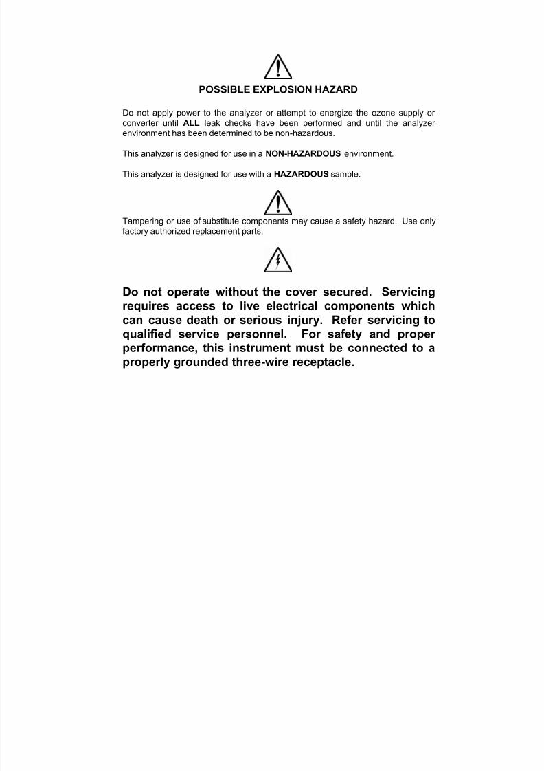
POSSIBLE EXPLOSION HAZARD
Do not apply power to the analyzer or attempt to energize the ozone supply or
converter until ALL leak checks have been performed and until the analyzer
environment has been determined to be non-hazardous.
This analyzer is designed for use in a NON-HAZARDOUS environment.
This analyzer is designed for use with a HAZARDOUS sample.
Tampering or use of substitute components may cause a safety hazard. Use only
factory authorized replacement parts.
Do not operate without the cover secured. Servicingrequires access to live electrical components which
can cause death or serious injury. Refer servicing toqualified service personnel. For safety and properperformance, this instrument must be connected to aproperly grounded three-wire receptacle.
7/23/2019 600 Series Cld Ops Manual 1213
http://slidepdf.com/reader/full/600-series-cld-ops-manual-1213 6/116
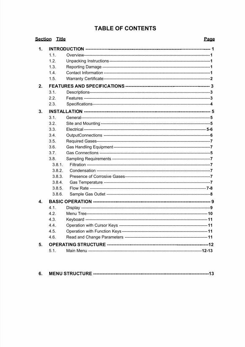
TABLE OF CONTENTS
Section Title Page
1. INTRODUCTION -------------------------------------------------------------------------------- 1
1.1. Overview------------------------------------------------------------------------------------------1
1.2. Unpacking Instructions ------------------------------------------------------------------------1
1.3. Reporting Damage -----------------------------------------------------------------------------1
1.4. Contact Information ----------------------------------------------------------------------------1
1.5. Warranty Certificate----------------------------------------------------------------------------2
2. FEATURES AND SPECIFICATIONS ------------------------------------------------------ 3
3.1. Descriptions--------------------------------------------------------------------------------------3
2.2. Features ------------------------------------------------------------------------------------------3
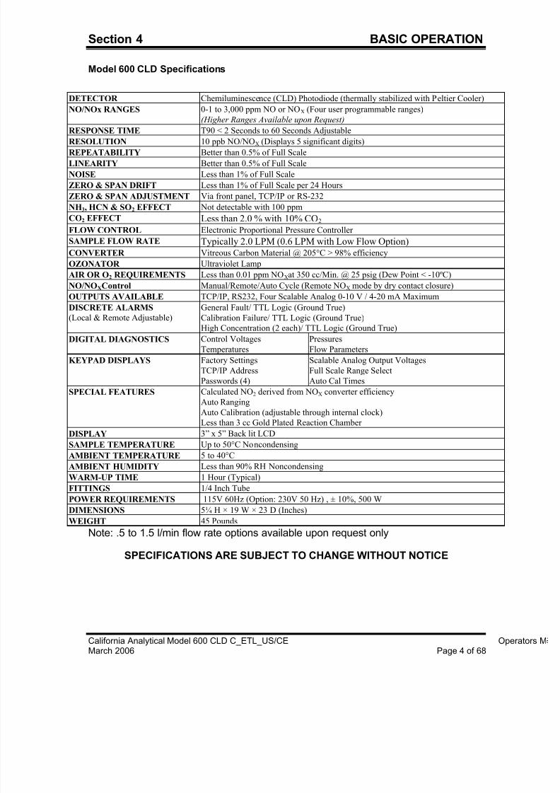
2.3. Specifications------------------------------------------------------------------------------------4
3. INSTALLATION --------------------------------------------------------------------------------- 5
3.1. General--------------------------------------------------------------------------------------------5 3.2. Site and Mounting ------------------------------------------------------------------------------5
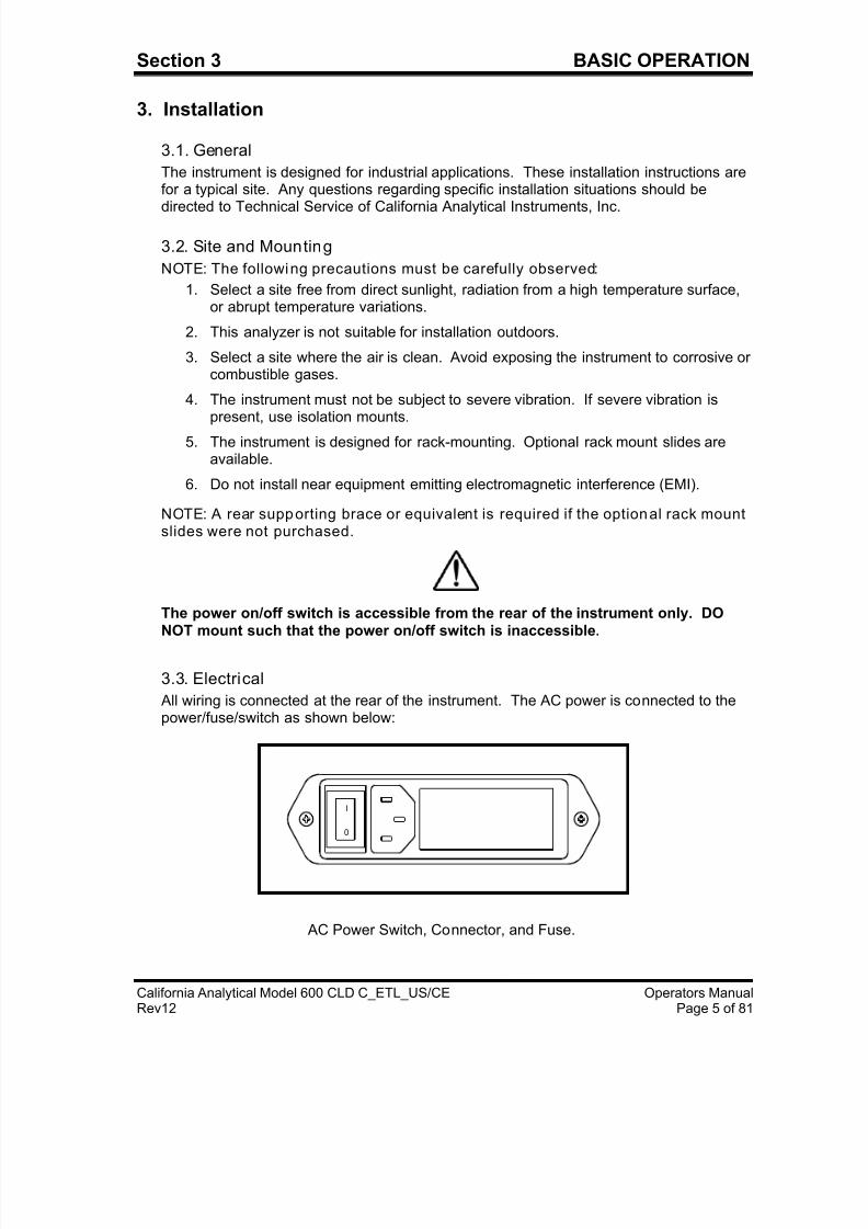
3.3. Electrical ---------------------------------------------------------------------------------------5-6
3.4. OutputConnections ----------------------------------------------------------------------------6
3.5. Required Gases---------------------------------------------------------------------------------7
3.6. Gas Handling Equipment---------------------------------------------------------------------7
3.7. Gas Connections -------------------------------------------------------------------------------5
3.8. Sampling Requirements ----------------------------------------------------------------------7
3.8.1. Filtration ----------------------------------------------------------------------------------------7
3.8.2. Condensation ---------------------------------------------------------------------------------7
3.8.3. Presence of Corrosive Gases-------------------------------------------------------------7
3.8.4. Gas Temperature ----------------------------------------------------------------------------7
3.8.5. Flow Rate -----------------------------------------------------------------------------------7-8
3.8.6. Sample Gas Outlet --------------------------------------------------------------------------8
4. BASIC OPERATION --------------------------------------------------------------------------- 9
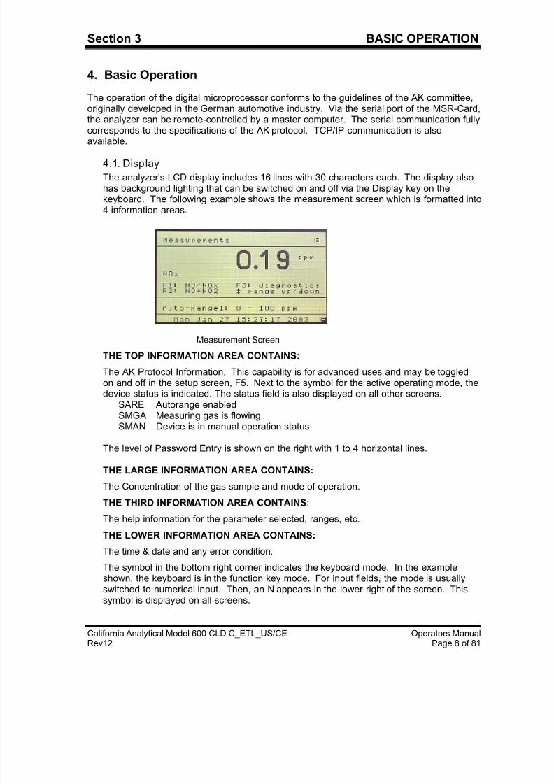
4.1. Display --------------------------------------------------------------------------------------------9
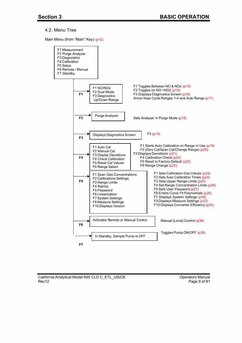
4.2. Menu Tree--------------------------------------------------------------------------------------10
4.3. Keyboard ---------------------------------------------------------------------------------------11
4.4. Operation with Cursor Keys ---------------------------------------------------------------11
4.5. Operation with Function Keys -------------------------------------------------------------11
4.6. Read and Change Parameters -----------------------------------------------------------11
5. OPERATING STRUCTURE -----------------------------------------------------------------12
5.1. Main Menu ---------------------------------------------------------------------------------12-13
6. MENU STRUCTURE --------------------------------------------------------------------------13
7/23/2019 600 Series Cld Ops Manual 1213
http://slidepdf.com/reader/full/600-series-cld-ops-manual-1213 7/116
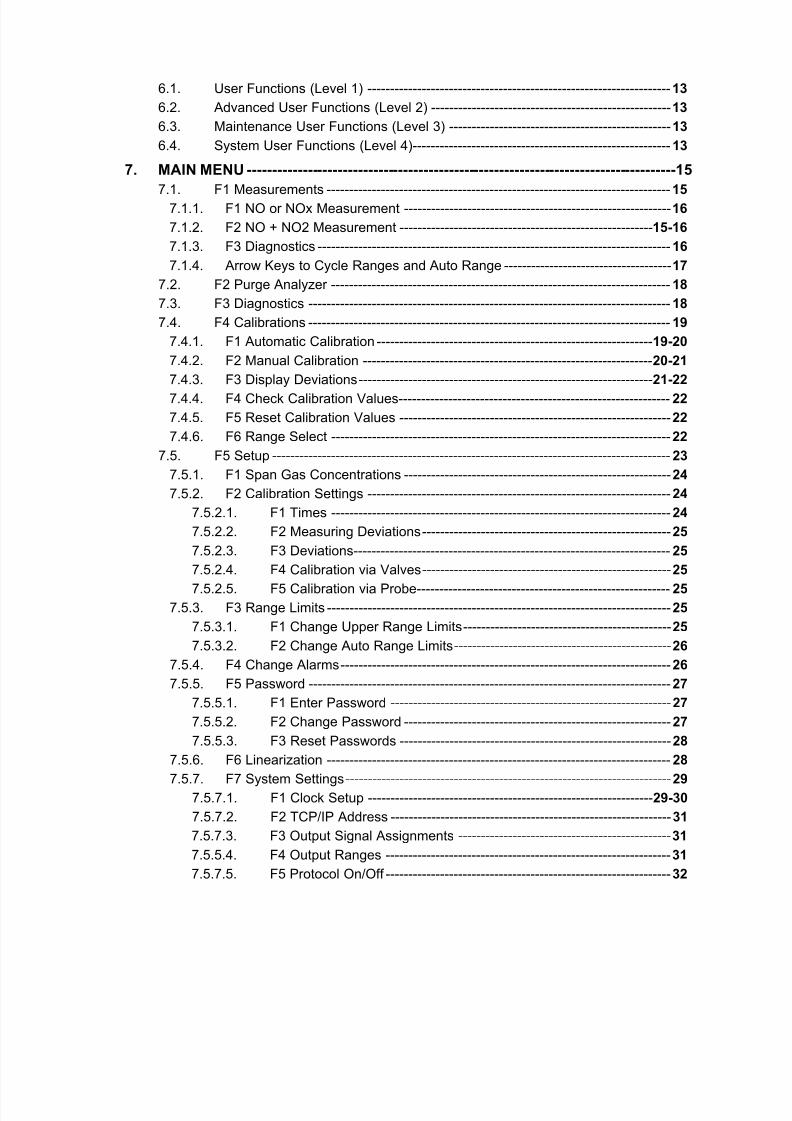
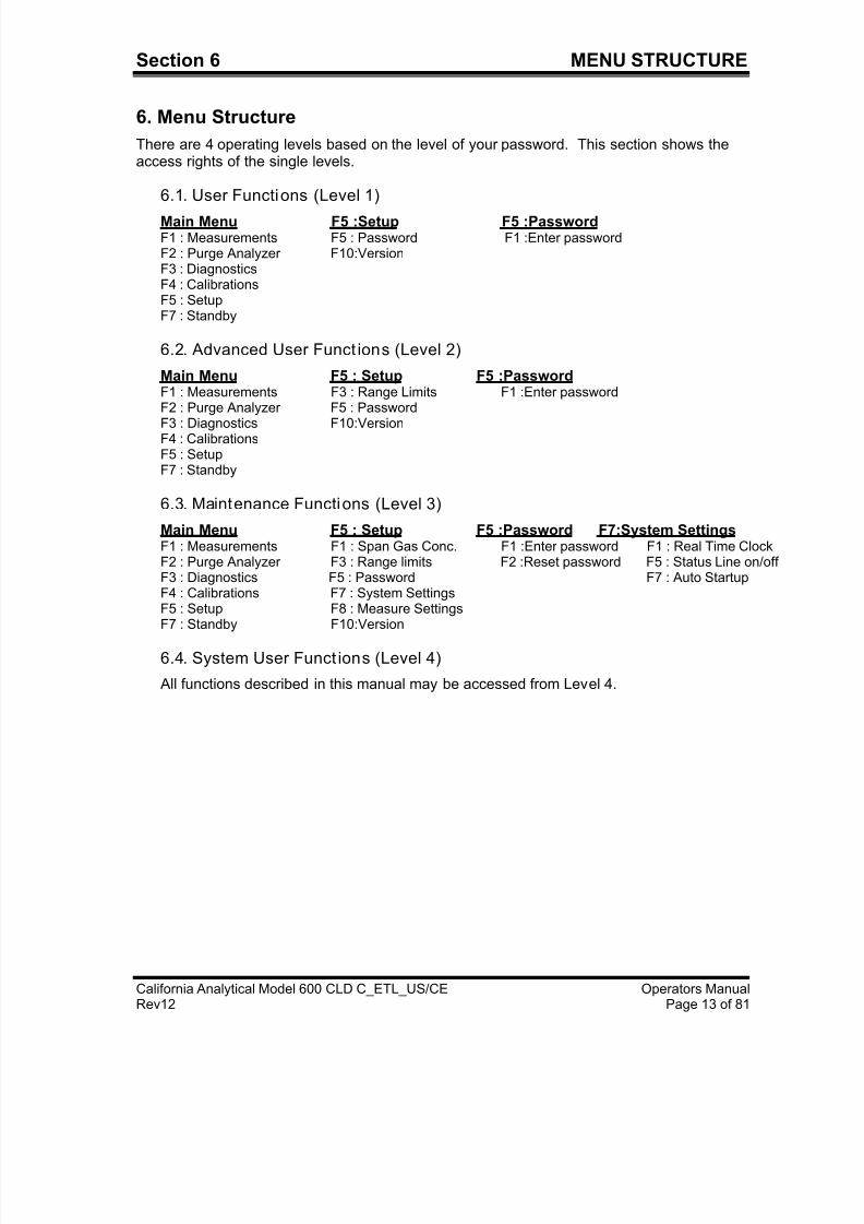
6.1. User Functions (Level 1) -------------------------------------------------------------------13
6.2. Advanced User Functions (Level 2) -----------------------------------------------------13
6.3. Maintenance User Functions (Level 3) ------------------------------------------------- 13
6.4. System User Functions (Level 4)--------------------------------------------------------- 13
7. MAIN MENU -------------------------------------------------------------------------------------15
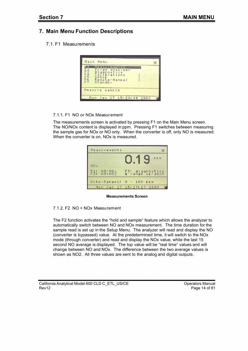
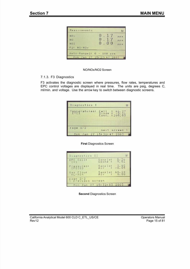
7.1. F1 Measurements ----------------------------------------------------------------------------15 7.1.1. F1 NO or NOx Measurement -----------------------------------------------------------16
7.1.2. F2 NO + NO2 Measurement --------------------------------------------------------15-16
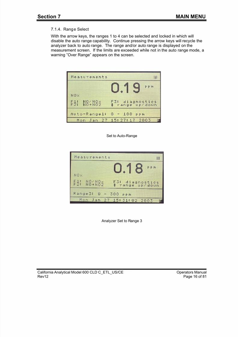
7.1.3. F3 Diagnostics ------------------------------------------------------------------------------16
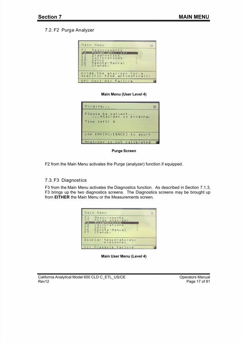
7.1.4. Arrow Keys to Cycle Ranges and Auto Range ------------------------------------- 17
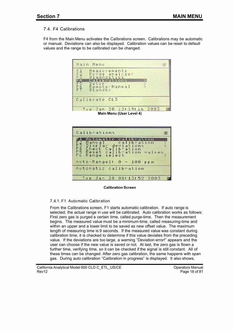
7.2. F2 Purge Analyzer ---------------------------------------------------------------------------18
7.3. F3 Diagnostics --------------------------------------------------------------------------------18
7.4. F4 Calibrations --------------------------------------------------------------------------------19
7.4.1. F1 Automatic Calibration -------------------------------------------------------------19-20
7.4.2. F2 Manual Calibration ----------------------------------------------------------------20-21
7.4.3. F3 Display Deviations-----------------------------------------------------------------21-22 7.4.4. F4 Check Calibration Values------------------------------------------------------------ 22
7.4.5. F5 Reset Calibration Values ------------------------------------------------------------22
7.4.6. F6 Range Select ---------------------------------------------------------------------------22
7.5. F5 Setup ----------------------------------------------------------------------------------------23
7.5.1. F1 Span Gas Concentrations ----------------------------------------------------------- 24
7.5.2. F2 Calibration Settings ------------------------------------------------------------------- 24
7.5.2.1. F1 Times ---------------------------------------------------------------------------24
7.5.2.2. F2 Measuring Deviations------------------------------------------------------- 25
7.5.2.3. F3 Deviations---------------------------------------------------------------------- 25
7.5.2.4. F4 Calibration via Valves-------------------------------------------------------25
7.5.2.5. F5 Calibration via Probe-------------------------------------------------------- 25
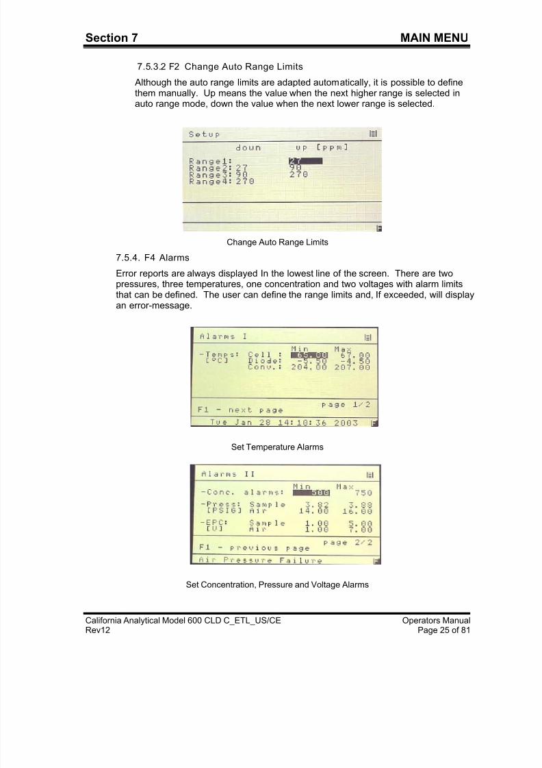
7.5.3. F3 Range Limits ----------------------------------------------------------------------------25
7.5.3.1. F1 Change Upper Range Limits----------------------------------------------25
7.5.3.2. F2 Change Auto Range Limits------------------------------------------------26
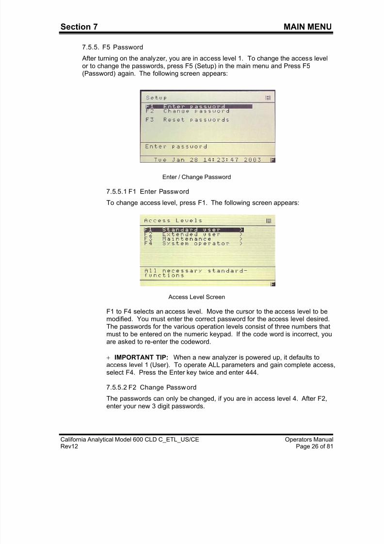
7.5.4. F4 Change Alarms-------------------------------------------------------------------------26
7.5.5. F5 Password --------------------------------------------------------------------------------27
7.5.5.1. F1 Enter Password --------------------------------------------------------------27
7.5.5.2. F2 Change Password ----------------------------------------------------------- 27
7.5.5.3. F3 Reset Passwords ------------------------------------------------------------ 28
7.5.6. F6 Linearization ----------------------------------------------------------------------------28
7.5.7. F7 System Settings------------------------------------------------------------------------29
7.5.7.1. F1 Clock Setup ---------------------------------------------------------------29-30
7.5.7.2. F2 TCP/IP Address --------------------------------------------------------------31
7.5.7.3. F3 Output Signal Assignments -----------------------------------------------31
7.5.5.4. F4 Output Ranges ---------------------------------------------------------------31
7.5.7.5. F5 Protocol On/Off ---------------------------------------------------------------32
7/23/2019 600 Series Cld Ops Manual 1213
http://slidepdf.com/reader/full/600-series-cld-ops-manual-1213 8/116
7.5.7.6. F6 Set Langauge-----------------------------------------------------------------32
7.5.7.7. F7 Automatic Setup-------------------------------------------------------------- 32
7.5.8. F8 Measure Settings ----------------------------------------------------------------------33
7.5.8.1. F1 Set Purge Time Before Measure----------------------------------------- 33
7.5.8.2. F2 Set Converter Efficieny ----------------------------------------------------- 33
7.5.8.3. F3 Set Time Constant-----------------------------------------------------------34 7.5.8.4. F4 Set Purge Time Before Calibration -------------------------------------- 34
7.5.10. F10 Display Software Version ------------------------------------------------------34-35
7.6. F7 Remote/Manual Operation------------------------------------------------------------- 35
7.7. F8 Standby -------------------------------------------------------------------------------------35
8. ANALYZER COMPONENTS----------------------------------------------------------------36
8.1. Rear Panel Connections--------------------------------------------------------------------36
8.1.1. Main Analog Connections---------------------------------------------------------------- 37
8.1.2. Auxiliary Analog Connections-----------------------------------------------------------37
8.1.3. Digital (RS-232) Connections -----------------------------------------------------------38
8.1.4. Digital (TCP/IP) Connections -----------------------------------------------------------38 8.2. Internal Components ------------------------------------------------------------------------39
8.3. Main Electronics Board (Potentiometers) ---------------------------------------------- 40
8.4. Main Electronics Board (Connections)-------------------------------------------------- 41
8.5. Reaction Chamber ---------------------------------------------------------------------------42
8.6. Relay Board (Connections) ---------------------------------------------------------------- 43
9. OPERATION-------------------------------------------------------------------------------------44
9.1. Preparation------------------------------------------------------------------------------------- 44
9.2. Operation -----------------------------------------------------------------------------------44-45
9.3. Shut Down Procedure-----------------------------------------------------------------------45
10. FUNCTIONAL DESCRIPTION--------------------------------------------------------------46
10.1. Operating Principle--------------------------------------------------------------------------- 46
10.2. Reaction Chamber Assembly -------------------------------------------------------------46
10.3. Flow System -----------------------------------------------------------------------------------46
10.4. Electronics-------------------------------------------------------------------------------------- 46
10.5. Main Electronics Board ---------------------------------------------------------------------47
10.6. Relay Board------------------------------------------------------------------------------------ 47
11. REACTION CHAMBER-----------------------------------------------------------------------48
11.1. Reaction Chamber Disassembly ---------------------------------------------------------48
11.2. Reaction Chamber Assembly -------------------------------------------------------------48
12. TROUBLESHOOTING------------------------------------------------------------------------49
12.1. Ozone Air/O2 Supply ------------------------------------------------------------------------49
12.2. Sample Supply --------------------------------------------------------------------------------49
12.3. NO/NOx Converter ---------------------------------------------------------------------------49
13. APPENDIX 1-------------------------------------------------------------------------------------50
13.1. AK Protocol --------------------------------------------------------------------------------51-62
7/23/2019 600 Series Cld Ops Manual 1213
http://slidepdf.com/reader/full/600-series-cld-ops-manual-1213 9/116
13.2. I/O Lists -----------------------------------------------------------------------------------------63
13.3. Flow Diagrams ----------------------------------------------------------------------------64-67
13.4. Electrical Block Diagram-------------------------------------------------------------------- 68
13.5 Serial Number UO6081--------------------------------------------------------------------70
7/23/2019 600 Series Cld Ops Manual 1213
http://slidepdf.com/reader/full/600-series-cld-ops-manual-1213 10/116
Section 1 INTRODUCTION
California Analytical Model 600 CLD C_ETL_US/CE Operators ManualRev12 Page 1 of 81
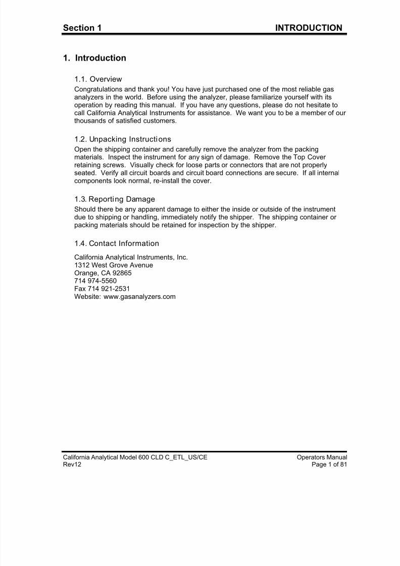
1. Introduction
1.1. Overview
Congratulations and thank you! You have just purchased one of the most reliable gas
analyzers in the world. Before using the analyzer, please familiarize yourself with itsoperation by reading this manual. If you have any questions, please do not hesitate tocall California Analytical Instruments for assistance. We want you to be a member of ourthousands of satisfied customers.
1.2. Unpacking Instructions
Open the shipping container and carefully remove the analyzer from the packingmaterials. Inspect the instrument for any sign of damage. Remove the Top Coverretaining screws. Visually check for loose parts or connectors that are not properlyseated. Verify all circuit boards and circuit board connections are secure. If all internalcomponents look normal, re-install the cover.
1.3. Reporting Damage
Should there be any apparent damage to either the inside or outside of the instrumentdue to shipping or handling, immediately notify the shipper. The shipping container orpacking materials should be retained for inspection by the shipper.
1.4. Contact Information
California Analytical Instruments, Inc.1312 West Grove AvenueOrange, CA 92865714 974-5560
Fax 714 921-2531Website: www.gasanalyzers.com
7/23/2019 600 Series Cld Ops Manual 1213
http://slidepdf.com/reader/full/600-series-cld-ops-manual-1213 11/116
Section 1 INTRODUCTION
California Analytical Model 600 CLD C_ETL_US/CE Operators ManualRev12 Page 2 of 81
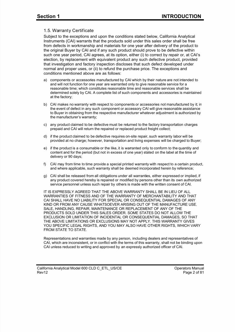
1.5. Warranty Certif icate
Subject to the exceptions and upon the conditions stated below, California AnalyticalInstruments (CAI) warrants that the products sold under this sales order shall be freefrom defects in workmanship and materials for one year after delivery of the product tothe original Buyer by CAI and if any such product should prove to be defective within
such one year period, CAI agrees, at its option, either (i) to correct by repair or, at CAI’selection, by replacement with equivalent product any such defective product, providedthat investigation and factory inspection discloses that such defect developed undernormal and proper uses, or (ii) to refund the purchase price. The exceptions andconditions mentioned above are as follows:
a) components or accessories manufactured by CAI which by their nature are not intended toand will not function for one year are warranted only to give reasonable service for areasonable time; which constitutes reasonable time and reasonable services shall bedetermined solely by CAl. A complete list of such components and accessories is maintainedat the factory;
b) CAI makes no warranty with respect to components or accessories not manufactured by it; inthe event of defect in any such component or accessory CAI will give reasonable assistance
to Buyer in obtaining from the respective manufacturer whatever adjustment is authorized bythe manufacturer’s warranty;
c) any product claimed to be defective must be returned to the factory transportation chargesprepaid and CAI will return the repaired or replaced product freight collect;
d) if the product claimed to be defective requires on-site repair, such warranty labor will beprovided at no charge; however, transportation and living expenses will be charged to Buyer;
e) if the product is a consumable or the like, it is warranted only to conform to the quantity andcontent and for the period (but not in excess of one year) stated on the label at the time ofdelivery or 90 days;
f) CAI may from time to time provide a special printed warranty with respect to a certain product,
and where applicable, such warranty shall be deemed incorporated herein by reference;
g) CAI shall be released from all obligations under all warranties, either expressed or implied, ifany product covered hereby is repaired or modified by persons other than its own authorizedservice personnel unless such repair by others is made with the written consent of CAl.
IT IS EXPRESSLY AGREED THAT THE ABOVE WARRANTY SHALL BE IN LIEU OF ALLWARRANTIES OF FITNESS AND OF THE WARRANTY OF MERCHANTABILITY AND THATCAI SHALL HAVE NO LIABILITY FOR SPECIAL OR CONSEQUENTIAL DAMAGES OF ANYKIND OR FROM ANY CAUSE WHATSOEVER ARISING OUT OF THE MANUFACTURE USE,SALE, HANDLING, REPAIR, MAINTENANCE OR REPLACEMENT OF ANY OF THEPRODUCTS SOLD UNDER THIS SALES ORDER. SOME STATES DO NOT ALLOW THEEXCLUSION OR LIMITATION OF INCIDENTAL OR CONSEQUENTIAL DAMAGES, SO THATTHE ABOVE LIMITATIONS OR EXCLUSIONS MAY NOT APPLY. THIS WARRANTY GIVESYOU SPECIFIC LEGAL RIGHTS, AND YOU MAY ALSO HAVE OTHER RIGHTS, WHICH VARYFROM STATE TO STATE.
Representations and warranties made by any person, including dealers and representatives ofCAI, which are inconsistent, or in conflict with the terms of this warranty, shall not be binding uponCAI unless reduced to writing and approved by an expressly authorized officer of CAl.
7/23/2019 600 Series Cld Ops Manual 1213
http://slidepdf.com/reader/full/600-series-cld-ops-manual-1213 12/116
7/23/2019 600 Series Cld Ops Manual 1213
http://slidepdf.com/reader/full/600-series-cld-ops-manual-1213 13/116
7/23/2019 600 Series Cld Ops Manual 1213
http://slidepdf.com/reader/full/600-series-cld-ops-manual-1213 14/116
7/23/2019 600 Series Cld Ops Manual 1213
http://slidepdf.com/reader/full/600-series-cld-ops-manual-1213 15/116
7/23/2019 600 Series Cld Ops Manual 1213
http://slidepdf.com/reader/full/600-series-cld-ops-manual-1213 16/116
Section 3 BASIC OPERATION
California Analytical Model 600 CLD C_ETL_US/CE Operators ManualRev12 Page 7 of 81
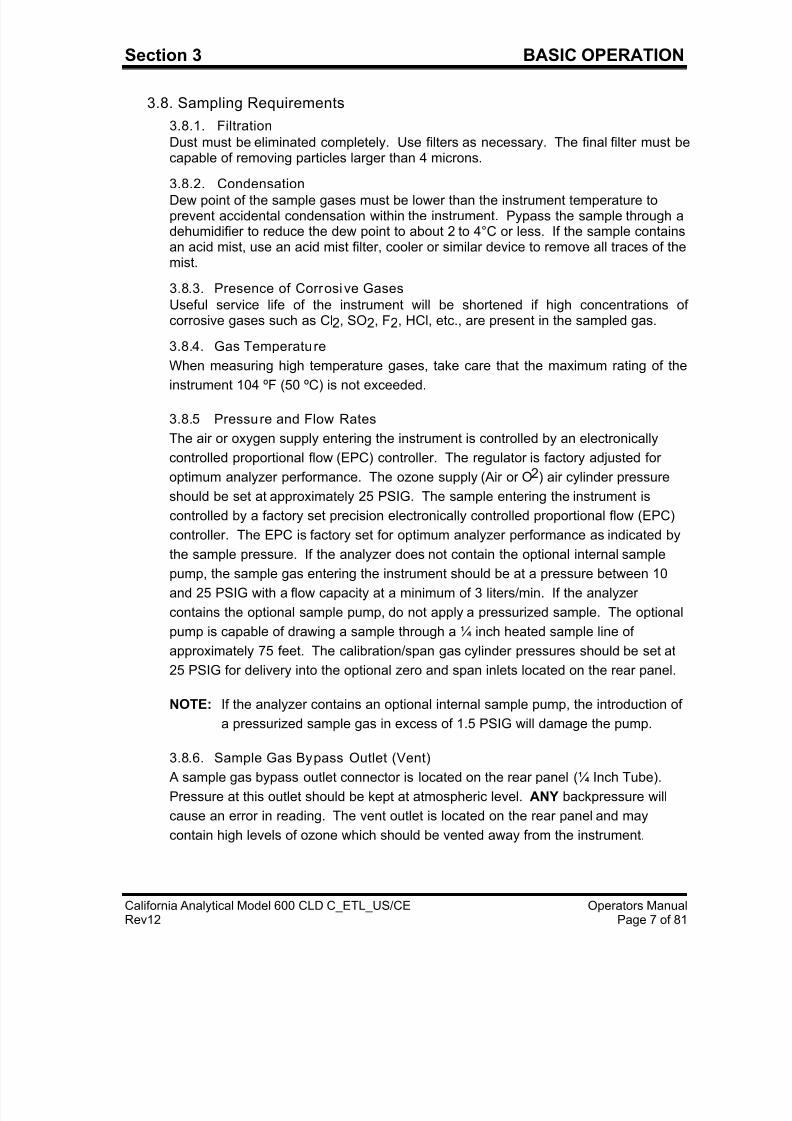
3.8. Sampling Requirements
3.8.1. Filtration
Dust must be eliminated completely. Use filters as necessary. The final filter must becapable of removing particles larger than 4 microns.
3.8.2. CondensationDew point of the sample gases must be lower than the instrument temperature toprevent accidental condensation within the instrument. Pypass the sample through adehumidifier to reduce the dew point to about 2 to 4°C or less. If the sample containsan acid mist, use an acid mist filter, cooler or similar device to remove all traces of themist.
3.8.3. Presence of Corrosive Gases
Useful service life of the instrument will be shortened if high concentrations ofcorrosive gases such as Cl2, SO2, F2, HCl, etc., are present in the sampled gas.
3.8.4. Gas Temperature
When measuring high temperature gases, take care that the maximum rating of the
instrument 104 ºF (50 ºC) is not exceeded.
3.8.5 Pressure and Flow Rates
The air or oxygen supply entering the instrument is controlled by an electronically
controlled proportional flow (EPC) controller. The regulator is factory adjusted for
optimum analyzer performance. The ozone supply (Air or O2) air cylinder pressure
should be set at approximately 25 PSIG. The sample entering the instrument is
controlled by a factory set precision electronically controlled proportional flow (EPC)
controller. The EPC is factory set for optimum analyzer performance as indicated by
the sample pressure. If the analyzer does not contain the optional internal sample
pump, the sample gas entering the instrument should be at a pressure between 10
and 25 PSIG with a flow capacity at a minimum of 3 liters/min. If the analyzer
contains the optional sample pump, do not apply a pressurized sample. The optional
pump is capable of drawing a sample through a ¼ inch heated sample line of
approximately 75 feet. The calibration/span gas cylinder pressures should be set at
25 PSIG for delivery into the optional zero and span inlets located on the rear panel.
NOTE: If the analyzer contains an optional internal sample pump, the introduction of
a pressurized sample gas in excess of 1.5 PSIG will damage the pump.
3.8.6. Sample Gas Bypass Outlet (Vent) A sample gas bypass outlet connector is located on the rear panel (¼ Inch Tube).
Pressure at this outlet should be kept at atmospheric level. ANY backpressure will
cause an error in reading. The vent outlet is located on the rear panel and may
contain high levels of ozone which should be vented away from the instrument.
7/23/2019 600 Series Cld Ops Manual 1213
http://slidepdf.com/reader/full/600-series-cld-ops-manual-1213 17/116
7/23/2019 600 Series Cld Ops Manual 1213
http://slidepdf.com/reader/full/600-series-cld-ops-manual-1213 18/116
7/23/2019 600 Series Cld Ops Manual 1213
http://slidepdf.com/reader/full/600-series-cld-ops-manual-1213 19/116
Section 3 BASIC OPERATION
California Analytical Model 600 CLD C_ETL_US/CE Operators ManualRev12 Page 10 of 81
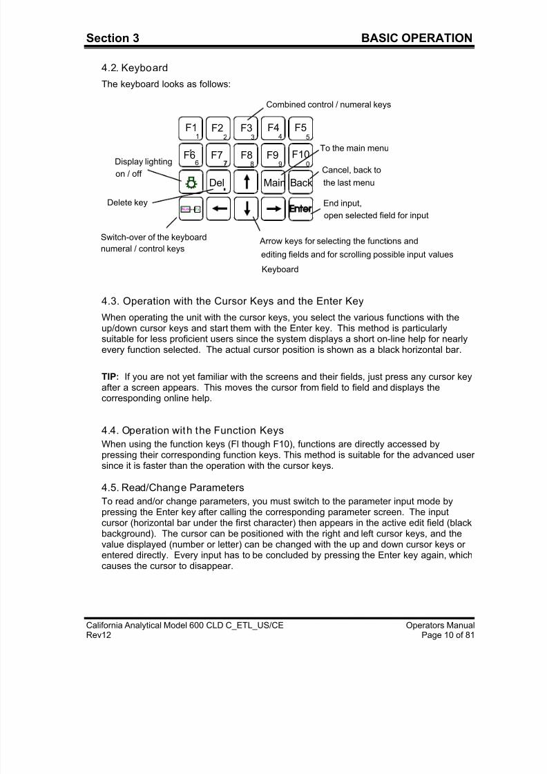
4.2. Keyboard
The keyboard looks as follows:
Del Main Back
6 7 8 9 0
1 2 3 4 5
F6 F7 F8 F9 F10
F1 F2 F3 F4 F5
Display lighting
on / off
Delete key
Switch-over of the keyboard
numeral / control keys
To the main menu
Cancel, back to
the last menu
End input,
open selected field for input
Arrow keys for selecting the functions and
editing fields and for scrolling possible input values
Combined control / numeral keys
Keyboard
4.3. Operation with the Cursor Keys and the Enter Key
When operating the unit with the cursor keys, you select the various functions with theup/down cursor keys and start them with the Enter key. This method is particularlysuitable for less proficient users since the system displays a short on-line help for nearlyevery function selected. The actual cursor position is shown as a black horizontal bar.
TIP: If you are not yet familiar with the screens and their fields, just press any cursor key
after a screen appears. This moves the cursor from field to field and displays thecorresponding online help.
4.4. Operation with the Function Keys
When using the function keys (Fl though F10), functions are directly accessed bypressing their corresponding function keys. This method is suitable for the advanced usersince it is faster than the operation with the cursor keys.
4.5. Read/Change Parameters
To read and/or change parameters, you must switch to the parameter input mode bypressing the Enter key after calling the corresponding parameter screen. The input
cursor (horizontal bar under the first character) then appears in the active edit field (blackbackground). The cursor can be positioned with the right and left cursor keys, and thevalue displayed (number or letter) can be changed with the up and down cursor keys orentered directly. Every input has to be concluded by pressing the Enter key again, whichcauses the cursor to disappear.
7/23/2019 600 Series Cld Ops Manual 1213
http://slidepdf.com/reader/full/600-series-cld-ops-manual-1213 20/116
Section 5 OPERATING STRUCTURE
California Analytical Model 600 CLD C_ETL_US/CE Operators ManualRev12 Page 11 of 81
5. Operating Structure
The analyzer’s operation can be divided into 4 operating levels. The current level is alwaysdisplayed as a stack of 1 to 4 horizontal bars in the top right corner of the screen. In theaccess level menu, you can choose between the following operating levels:
F1 User (operating level 1)F2 Advanced user (operating level 2)F3 Maintenance (operating level 3)F4 System user (operating level 4)
A password can be assigned to each operating level. Only the system user, who normallyhas the highest operating priority, can assign the password. At the factory, the defaultpasswords for the CAI analyzers are set as follows:
User: 111 Advanced user: 222Maintenance: 333System: 444
The default setting can be changed only by the system user. This manual is written toinclude all information for the advanced system user.
TIP: Because of the user settings, some of the parameters shown in this manual may notappear on your analyzer. Check the access level.
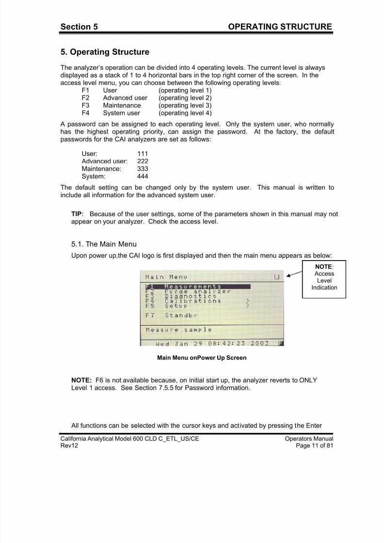
5.1. The Main Menu
Upon power up,the CAI logo is first displayed and then the main menu appears as below:
Main Menu onPower Up Screen
NOTE: F6 is not available because, on initial start up, the analyzer reverts to ONLYLevel 1 access. See Section 7.5.5 for Password information.
All functions can be selected with the cursor keys and activated by pressing the Enter
NOTE:
AccessLevel
Indication
7/23/2019 600 Series Cld Ops Manual 1213
http://slidepdf.com/reader/full/600-series-cld-ops-manual-1213 21/116
Section 5 OPERATING STRUCTURE
California Analytical Model 600 CLD C_ETL_US/CE Operators ManualRev12 Page 12 of 81
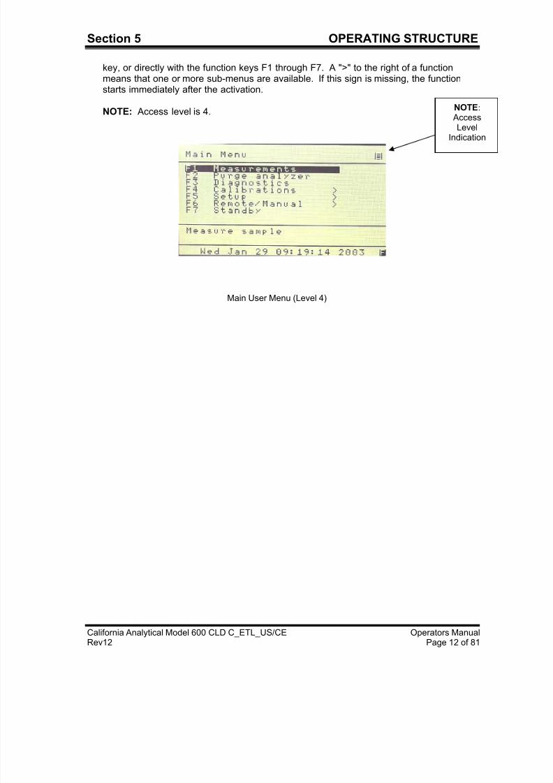
key, or directly with the function keys F1 through F7. A ">" to the right of a functionmeans that one or more sub-menus are available. If this sign is missing, the functionstarts immediately after the activation.
NOTE: Access level is 4.
Main User Menu (Level 4)
NOTE:
Access
LevelIndication
7/23/2019 600 Series Cld Ops Manual 1213
http://slidepdf.com/reader/full/600-series-cld-ops-manual-1213 22/116
7/23/2019 600 Series Cld Ops Manual 1213
http://slidepdf.com/reader/full/600-series-cld-ops-manual-1213 23/116
7/23/2019 600 Series Cld Ops Manual 1213
http://slidepdf.com/reader/full/600-series-cld-ops-manual-1213 24/116
7/23/2019 600 Series Cld Ops Manual 1213
http://slidepdf.com/reader/full/600-series-cld-ops-manual-1213 25/116
7/23/2019 600 Series Cld Ops Manual 1213
http://slidepdf.com/reader/full/600-series-cld-ops-manual-1213 26/116
7/23/2019 600 Series Cld Ops Manual 1213
http://slidepdf.com/reader/full/600-series-cld-ops-manual-1213 27/116
7/23/2019 600 Series Cld Ops Manual 1213
http://slidepdf.com/reader/full/600-series-cld-ops-manual-1213 28/116
7/23/2019 600 Series Cld Ops Manual 1213
http://slidepdf.com/reader/full/600-series-cld-ops-manual-1213 29/116
7/23/2019 600 Series Cld Ops Manual 1213
http://slidepdf.com/reader/full/600-series-cld-ops-manual-1213 30/116
7/23/2019 600 Series Cld Ops Manual 1213
http://slidepdf.com/reader/full/600-series-cld-ops-manual-1213 31/116
7/23/2019 600 Series Cld Ops Manual 1213
http://slidepdf.com/reader/full/600-series-cld-ops-manual-1213 32/116
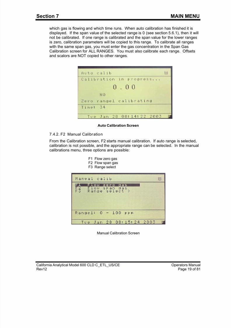
Section 7 MAIN MENU
California Analytical Model 600 CLD C_ETL_US/CE Operators ManualRev12 Page 23 of 81
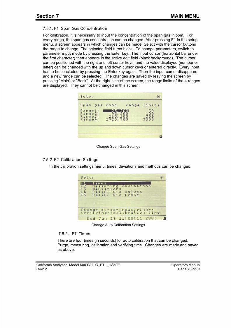
7.5.1. F1 Span Gas Concentration
For calibration, it is necessary to input the concentration of the span gas in ppm. Forevery range, the span gas concentration can be changed. After pressing F1 in the setupmenu, a screen appears in which changes can be made. Select with the cursor buttonsthe range to change. The selected field turns black. To change parameters, switch to
parameter input mode by pressing the Enter key. The input cursor (horizontal bar underthe first character) then appears in the active edit field (black background). The cursorcan be positioned with the right and left cursor keys, and the value displayed (number orletter) can be changed with the up and down cursor keys or entered directly. Every inputhas to be concluded by pressing the Enter key again. Then the input cursor disappearsand a new range can be selected. The changes are saved by leaving the screen bypressing ”Main” or ”Back”. At the right side of the screen, the range limits of the 4 rangesare displayed. They cannot be changed in this screen.
Change Span Gas Settings
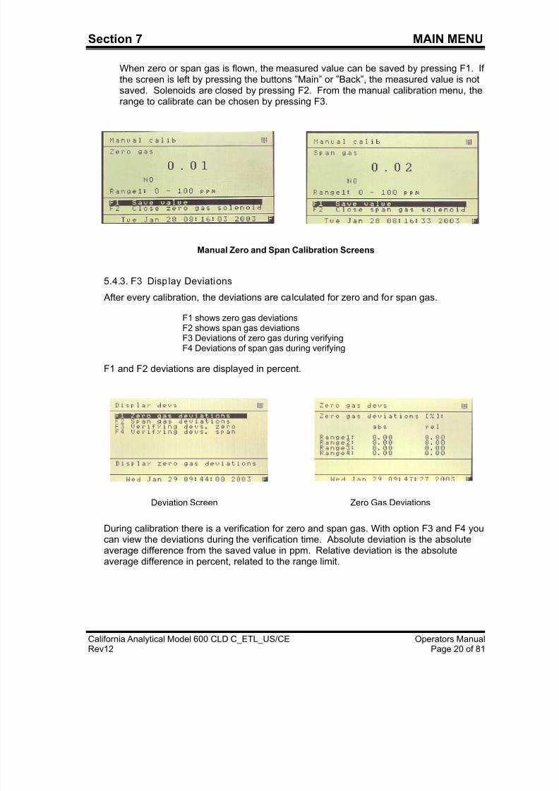
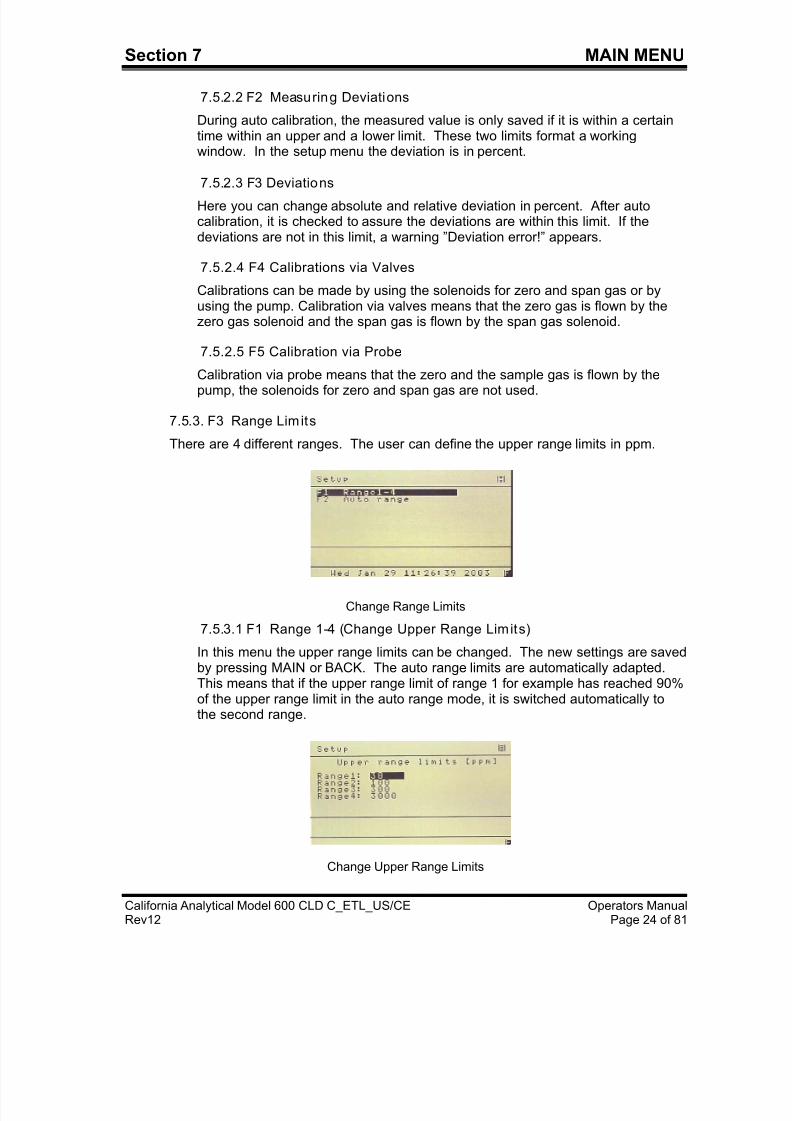
7.5.2. F2 Calibration Settings
In the calibration settings menu, times, deviations and methods can be changed.
Change Auto Calibration Settings
7.5.2.1 F1 Times
There are four times (in seconds) for auto calibration that can be changed.Purge, measuring, calibration and verifying time. Changes are made and savedas above.
7/23/2019 600 Series Cld Ops Manual 1213
http://slidepdf.com/reader/full/600-series-cld-ops-manual-1213 33/116
7/23/2019 600 Series Cld Ops Manual 1213
http://slidepdf.com/reader/full/600-series-cld-ops-manual-1213 34/116
7/23/2019 600 Series Cld Ops Manual 1213
http://slidepdf.com/reader/full/600-series-cld-ops-manual-1213 35/116
7/23/2019 600 Series Cld Ops Manual 1213
http://slidepdf.com/reader/full/600-series-cld-ops-manual-1213 36/116
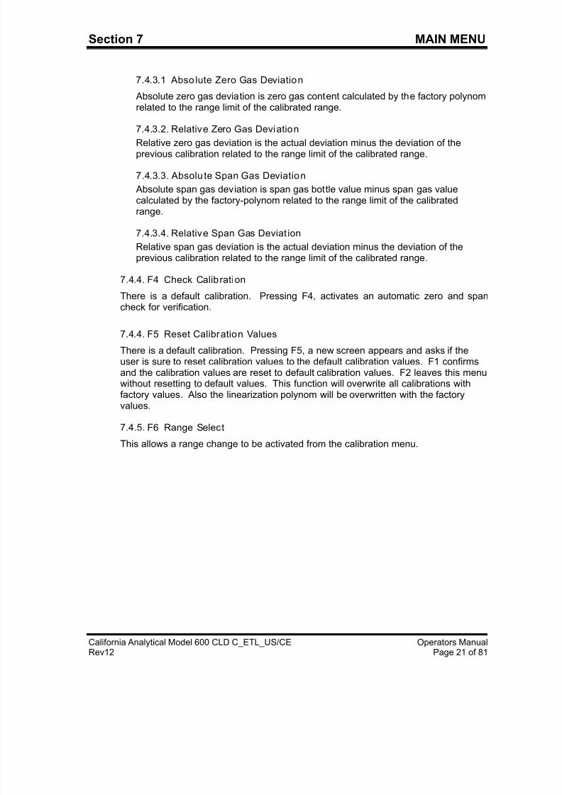
Section 7 MAIN MENU
California Analytical Model 600 CLD C_ETL_US/CE Operators ManualRev12 Page 27 of 81
+ IMPORTANT TIP: You MUST remember and record this new password. Ifthis is lost, you will need to consult the factory for the default password !!
7.5.5.3 F3 Reset Passwords
The passwords can only be changed, if you are in access level 4. Resetpasswords will revert back to the factory defaults.
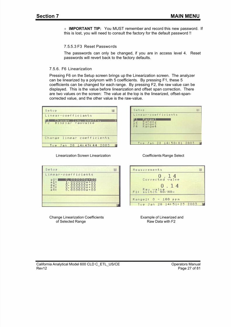
7.5.6. F6 Linearization
Pressing F6 on the Setup screen brings up the Linearization screen. The analyzercan be linearized by a polynom with 5 coefficients. By pressing F1, these 5coefficients can be changed for each range. By pressing F2, the raw value can bedisplayed. This is the value before linearization and offset span correction. Thereare two values on the screen: The value at the top is the linearized, offset-span-corrected value, and the other value is the raw-value.
Linearization Screen Linearization Coefficients Range Select
Change Linearization Coefficients Example of Linearized and
of Selected Range Raw Data with F2
7/23/2019 600 Series Cld Ops Manual 1213
http://slidepdf.com/reader/full/600-series-cld-ops-manual-1213 37/116
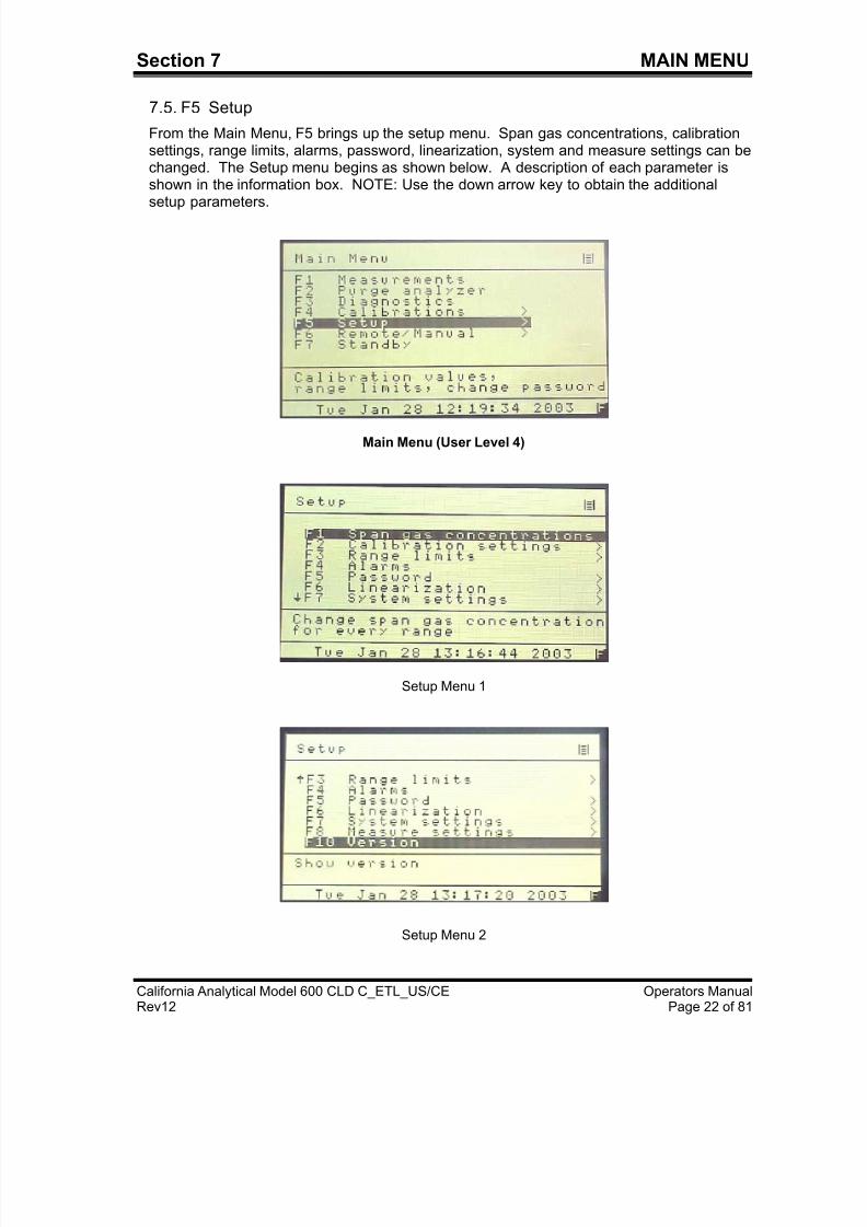
Section 7 MAIN MENU
California Analytical Model 600 CLD C_ETL_US/CE Operators ManualRev12 Page 28 of 81
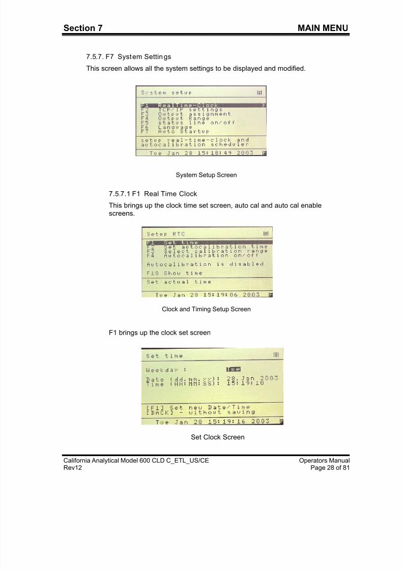
7.5.7. F7 System Settings
This screen allows all the system settings to be displayed and modified.
System Setup Screen
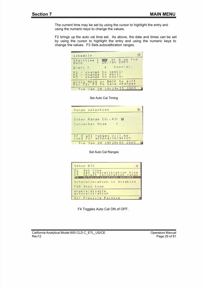
7.5.7.1 F1 Real Time Clock
This brings up the clock time set screen, auto cal and auto cal enablescreens.
Clock and Timing Setup Screen
F1 brings up the clock set screen
Set Clock Screen
7/23/2019 600 Series Cld Ops Manual 1213
http://slidepdf.com/reader/full/600-series-cld-ops-manual-1213 38/116
7/23/2019 600 Series Cld Ops Manual 1213
http://slidepdf.com/reader/full/600-series-cld-ops-manual-1213 39/116
7/23/2019 600 Series Cld Ops Manual 1213
http://slidepdf.com/reader/full/600-series-cld-ops-manual-1213 40/116
Section 7 MAIN MENU
California Analytical Model 600 CLD C_ETL_US/CE Operators ManualRev12 Page 31 of 81
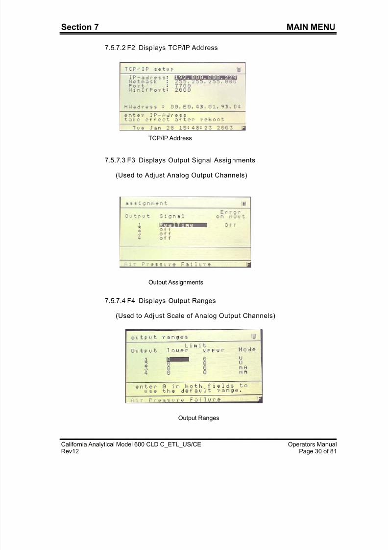
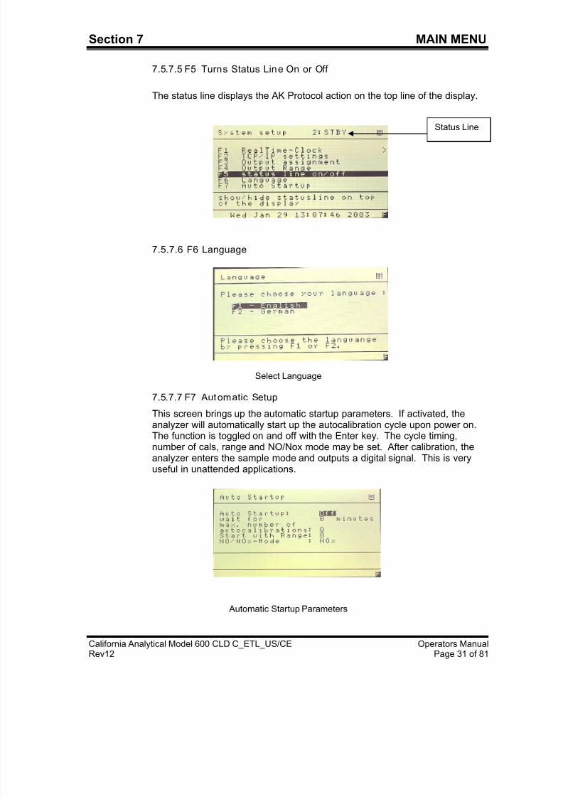
7.5.7.5 F5 Turns Status Line On or Off
The status line displays the AK Protocol action on the top line of the display.
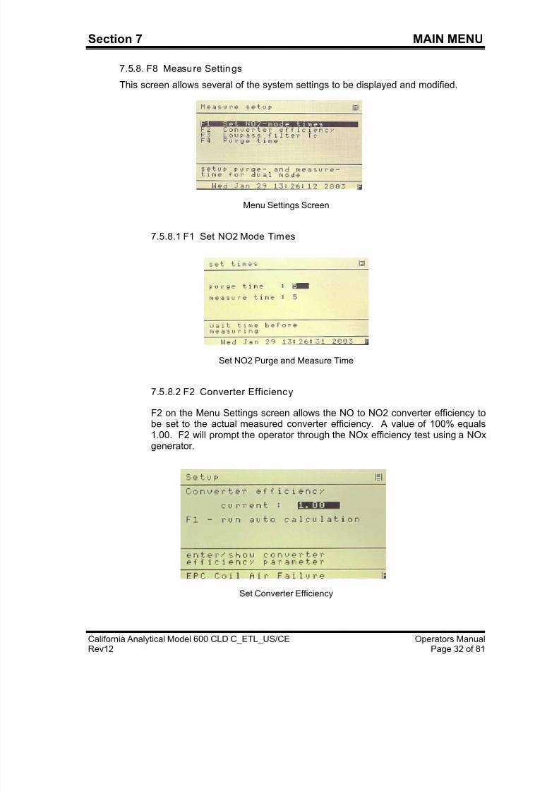
7.5.7.6 F6 Language
Select Language
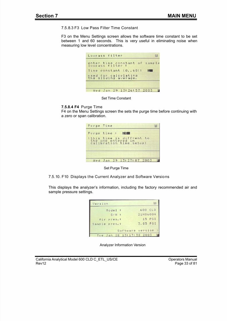
7.5.7.7 F7 Automatic Setup
This screen brings up the automatic startup parameters. If activated, theanalyzer will automatically start up the autocalibration cycle upon power on.The function is toggled on and off with the Enter key. The cycle timing,number of cals, range and NO/Nox mode may be set. After calibration, theanalyzer enters the sample mode and outputs a digital signal. This is veryuseful in unattended applications.
Automatic Startup Parameters
Status Line
7/23/2019 600 Series Cld Ops Manual 1213
http://slidepdf.com/reader/full/600-series-cld-ops-manual-1213 41/116
Section 7 MAIN MENU
California Analytical Model 600 CLD C_ETL_US/CE Operators ManualRev12 Page 32 of 81
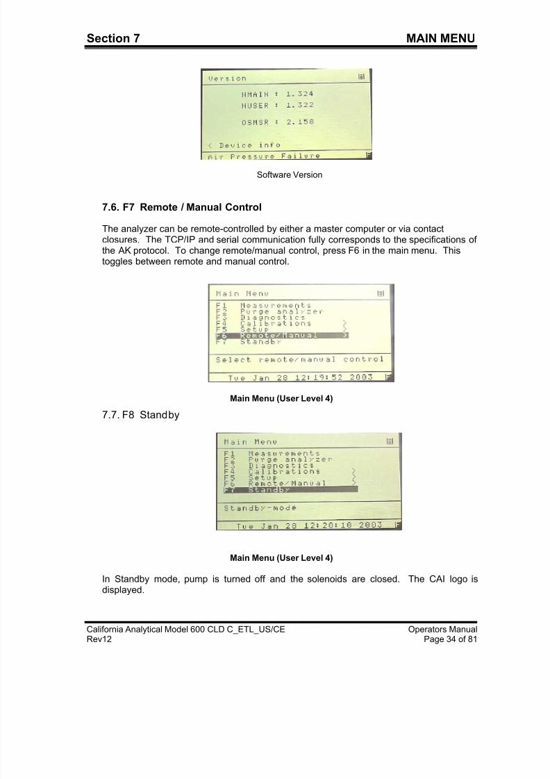
7.5.8. F8 Measure Settings
This screen allows several of the system settings to be displayed and modified.
Menu Settings Screen
7.5.8.1 F1 Set NO2 Mode Times
Set NO2 Purge and Measure Time
7.5.8.2 F2 Converter Efficiency
F2 on the Menu Settings screen allows the NO to NO2 converter efficiency tobe set to the actual measured converter efficiency. A value of 100% equals1.00. F2 will prompt the operator through the NOx efficiency test using a NOxgenerator.
Set Converter Efficiency
7/23/2019 600 Series Cld Ops Manual 1213
http://slidepdf.com/reader/full/600-series-cld-ops-manual-1213 42/116
Section 7 MAIN MENU
California Analytical Model 600 CLD C_ETL_US/CE Operators ManualRev12 Page 33 of 81
7.5.8.3 F3 Low Pass Filter Time Constant
F3 on the Menu Settings screen allows the software time constant to be setbetween 1 and 60 seconds. This is very useful in eliminating noise whenmeasuring low level concentrations.
Set Time Constant
7.5.8.4 F4 Purge Time F4 on the Menu Settings screen the sets the purge time before continuing witha zero or span calibration.
Set Purge Time
7.5.10. F10 Displays the Current Analyzer and Software Versions
This displays the analyzer’s information, including the factory recommended air andsample pressure settings.
Analyzer Information Version
7/23/2019 600 Series Cld Ops Manual 1213
http://slidepdf.com/reader/full/600-series-cld-ops-manual-1213 43/116
Section 7 MAIN MENU
California Analytical Model 600 CLD C_ETL_US/CE Operators ManualRev12 Page 34 of 81
Software Version
7.6. F7 Remote / Manual Control
The analyzer can be remote-controlled by either a master computer or via contactclosures. The TCP/IP and serial communication fully corresponds to the specifications ofthe AK protocol. To change remote/manual control, press F6 in the main menu. This
toggles between remote and manual control.
Main Menu (User Level 4)
7.7. F8 Standby
Main Menu (User Level 4)
In Standby mode, pump is turned off and the solenoids are closed. The CAI logo isdisplayed.
7/23/2019 600 Series Cld Ops Manual 1213
http://slidepdf.com/reader/full/600-series-cld-ops-manual-1213 44/116
Section 8 ANALYZER COMPONENTS
California Analytical Model 600 CLD C_ETL_US/CE Operators ManualRev12 Page 35 of 81
8. Analyzer Components
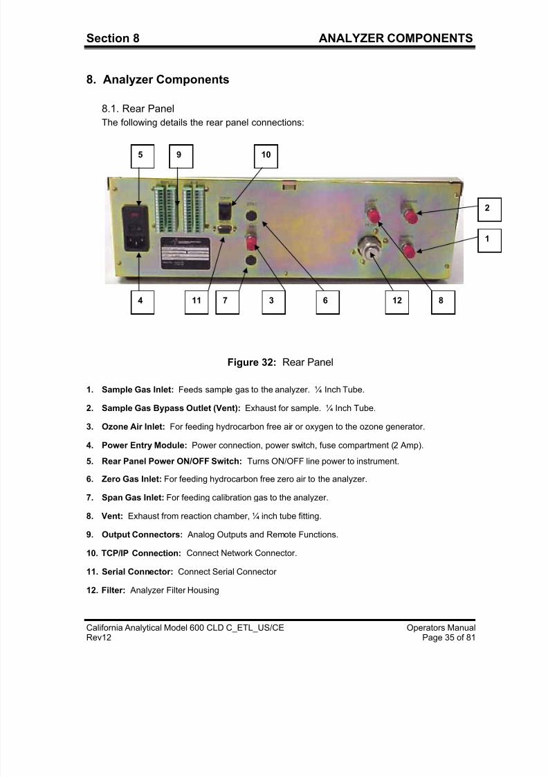
8.1. Rear Panel
The following details the rear panel connections:
Figure 32: Rear Panel
1. Sample Gas Inlet: Feeds sample gas to the analyzer. ¼ Inch Tube.
2. Sample Gas Bypass Outlet (Vent): Exhaust for sample. ¼ Inch Tube.
3. Ozone Air Inlet: For feeding hydrocarbon free air or oxygen to the ozone generator.
4. Power Entry Module: Power connection, power switch, fuse compartment (2 Amp).
5. Rear Panel Power ON/OFF Switch: Turns ON/OFF line power to instrument.
6. Zero Gas Inlet: For feeding hydrocarbon free zero air to the analyzer.
7. Span Gas Inlet: For feeding calibration gas to the analyzer.
8. Vent: Exhaust from reaction chamber, ¼ inch tube fitting.
9. Output Connectors: Analog Outputs and Remote Functions.
10. TCP/IP Connection: Connect Network Connector.
11. Serial Connector: Connect Serial Connector
12. Filter: Analyzer Filter Housing
2
1
812
10
637114
5 9
7/23/2019 600 Series Cld Ops Manual 1213
http://slidepdf.com/reader/full/600-series-cld-ops-manual-1213 45/116
Section 8 ANALYZER COMPONENTS
California Analytical Model 600 CLD C_ETL_US/CE Operators ManualRev12 Page 36 of 81
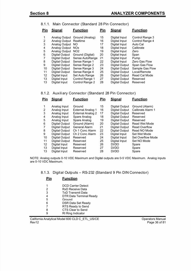
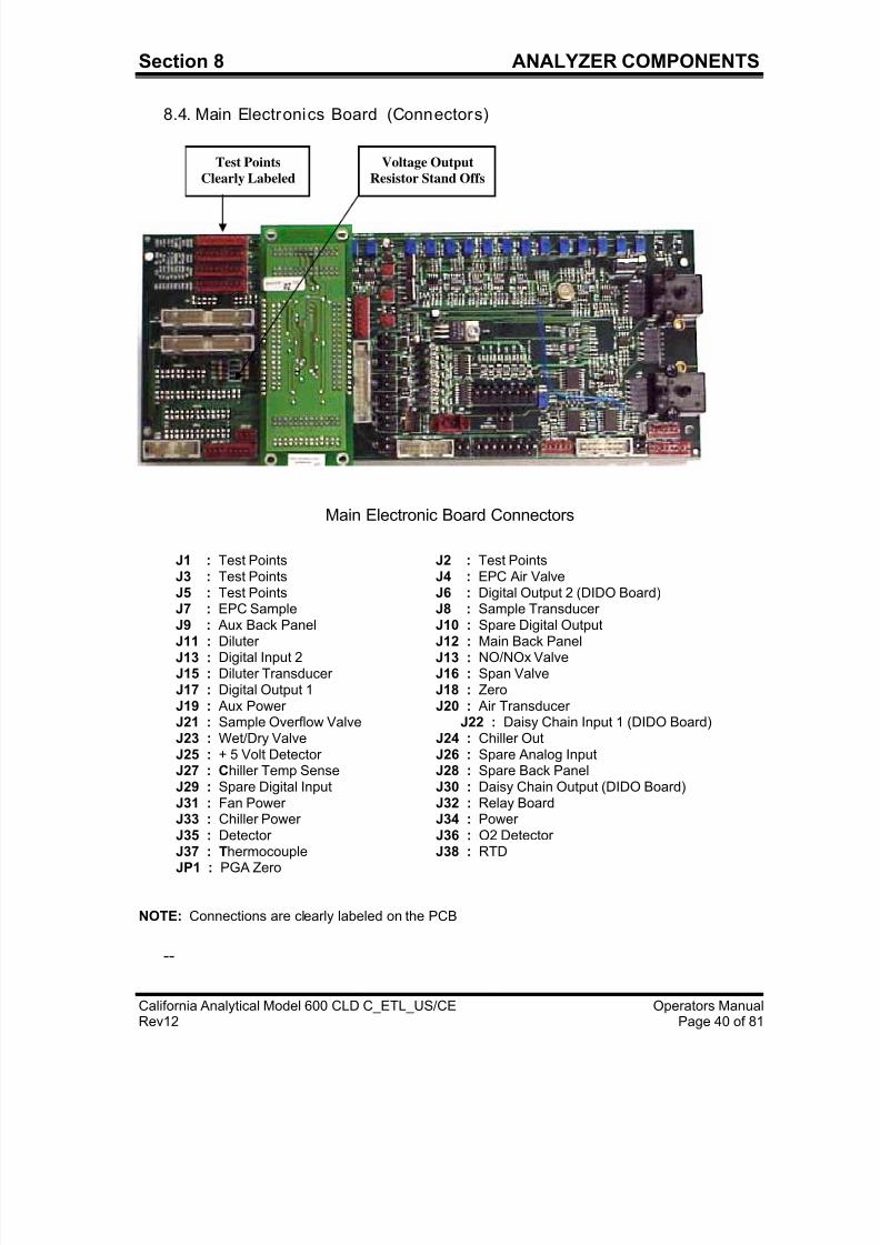
8.1.1. Main Connector (Standard 28 Pin Connector)
Pin Signal Function Pin Signal Function
1 Analog Output Ground (Analog) 15 Digital Input Control Range 32 Analog Output Realtime 16 Digital Input Control Range 4
3 Analog Output NO 17 Digital Input Auto Cal4 Analog Output NOx 18 Digital Input Calibrate5 Analog Output NO2 19 Digital Input Zero6 Digital Output Ground (Digital) 20 Digital Input Span7 Digital Output Sense AutoRange 21 Digital Input Pump8 Digital Output Sense Range 1 22 Digital Input Zero Gas Flow9 Digital Output Sense Range 2 23 Digital Output Span Gas Flow10 Digital Output Sense Range 3 24 Digital Output Sample Gas Flow11 Digital Output Sense Range 4 25 Digital Output Local/Remote12 Digital Input Set Auto Range 26 Digital Output Read Cal Mode13 Digital Input Control Range 1 27 Digital Output Reserved13 Digital Input Control Range 2 28 Digital Output Reserved
8.1.2. Auxiliary Connector (Standard 28 Pin Connector)
Pin Signal Function Pin Signal Function
1 Analog Input Ground 15 Digital Output Ground (Alarm)2 Analog Input External Analog 1 16 Digital Output Calibrate Alarm 13 Analog Input External Analog 2 17 Digital Output Reserved4 Analog Input Spare Analog 18 Digital Output Reserved5 Analog Input Spare Analog 19 Digital Output Reserved6 Digital Output Ground (Alarm) 20 Digital Output Read Wet Mode7 Digital Output General Alarm 21 Digital Output Read Overflow8 Digital Output Ch 1 Conc Alarm 22 Digital Output Read NO Mode9 Digital Output Ch 2 Conc Alarm 23 Digital Input Set Wet Mode
10 Digital Output Reserved 24 Digital Input Set Overflow Mode11 Digital Output Reserved 25 Digital Input Set NO Mode12 Digital Input Reserved 26 DI/DO Spare13 Digital Input Reserved 27 DI/DO Spare13 Digital Input Reserved 28 DI/DO Spare
NOTE: Analog outputs 0-10 VDC Maximum and Digital outputs are 0-5 VDC Maximum. Analog inputsare 0-10 VDC Maximum.
8.1.3. Digital Outputs – RS-232 (Standard 9 Pin DIN Connector)
Pin Function
1 DCD Carrier Detect2 RxD Receive Data3 TxD Transmit Data4 DTR Data Terminal Ready5 Ground6 DSR Data Set Ready7 RTS Ready to Send8 CTS Clear to Send9 RI Ring Indicator
7/23/2019 600 Series Cld Ops Manual 1213
http://slidepdf.com/reader/full/600-series-cld-ops-manual-1213 46/116
7/23/2019 600 Series Cld Ops Manual 1213
http://slidepdf.com/reader/full/600-series-cld-ops-manual-1213 47/116
7/23/2019 600 Series Cld Ops Manual 1213
http://slidepdf.com/reader/full/600-series-cld-ops-manual-1213 48/116
Section 8 ANALYZER COMPONENTS
California Analytical Model 600 CLD C_ETL_US/CE Operators ManualRev12 Page 39 of 81
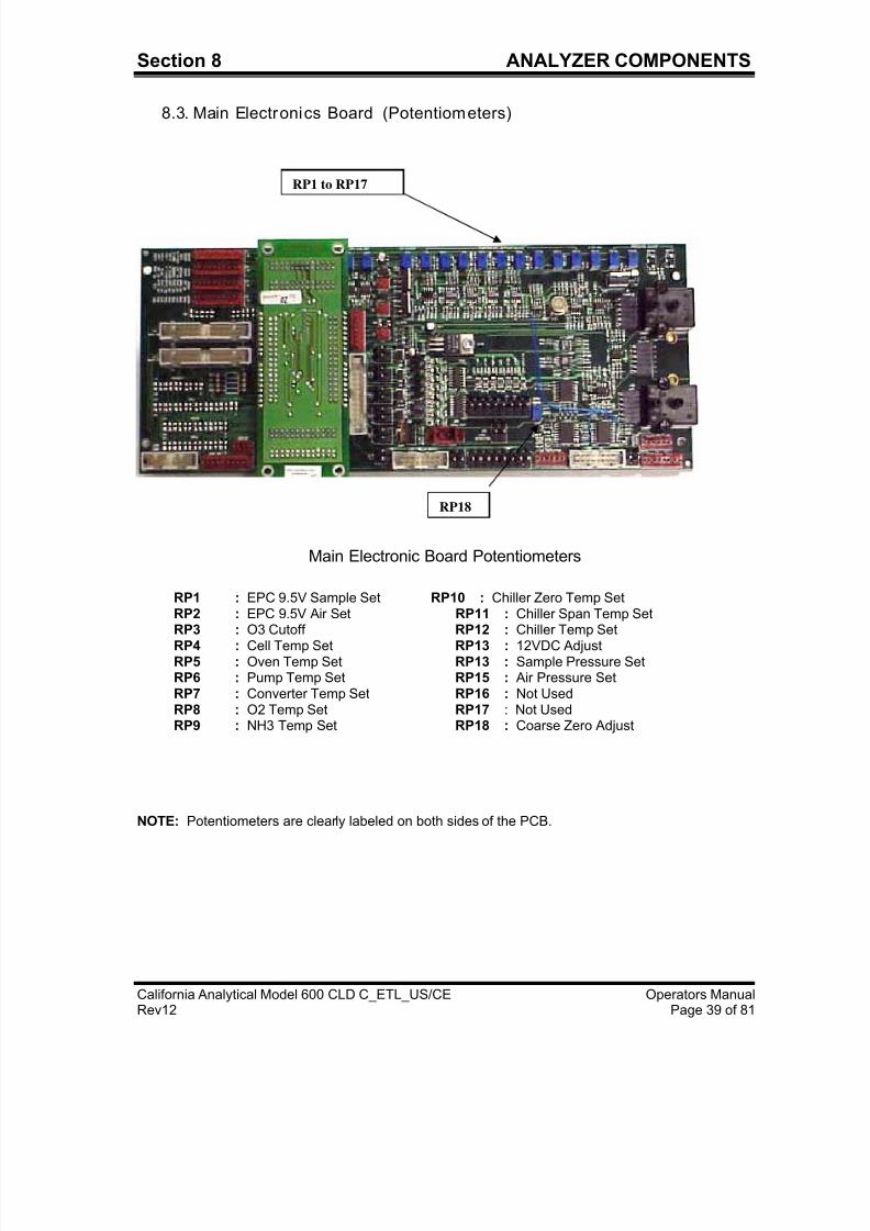
8.3. Main Electronics Board (Potentiometers)
Main Electronic Board Potentiometers
RP1 : EPC 9.5V Sample Set RP10 : Chiller Zero Temp SetRP2 : EPC 9.5V Air Set RP11 : Chiller Span Temp Set RP3 : O3 Cutoff RP12 : Chiller Temp Set RP4 : Cell Temp Set RP13 : 12VDC Adjust RP5 : Oven Temp Set RP13 : Sample Pressure Set RP6 : Pump Temp Set RP15 : Air Pressure Set RP7 : Converter Temp Set RP16 : Not Used RP8 : O2 Temp Set RP17 : Not Used RP9 : NH3 Temp Set RP18 : Coarse Zero Adjust
NOTE: Potentiometers are clearly labeled on both sides of the PCB.
RP1 to RP17
RP18
7/23/2019 600 Series Cld Ops Manual 1213
http://slidepdf.com/reader/full/600-series-cld-ops-manual-1213 49/116
7/23/2019 600 Series Cld Ops Manual 1213
http://slidepdf.com/reader/full/600-series-cld-ops-manual-1213 50/116
Section 8 ANALYZER COMPONENTS
California Analytical Model 600 CLD C_ETL_US/CE Operators ManualRev12 Page 41 of 81
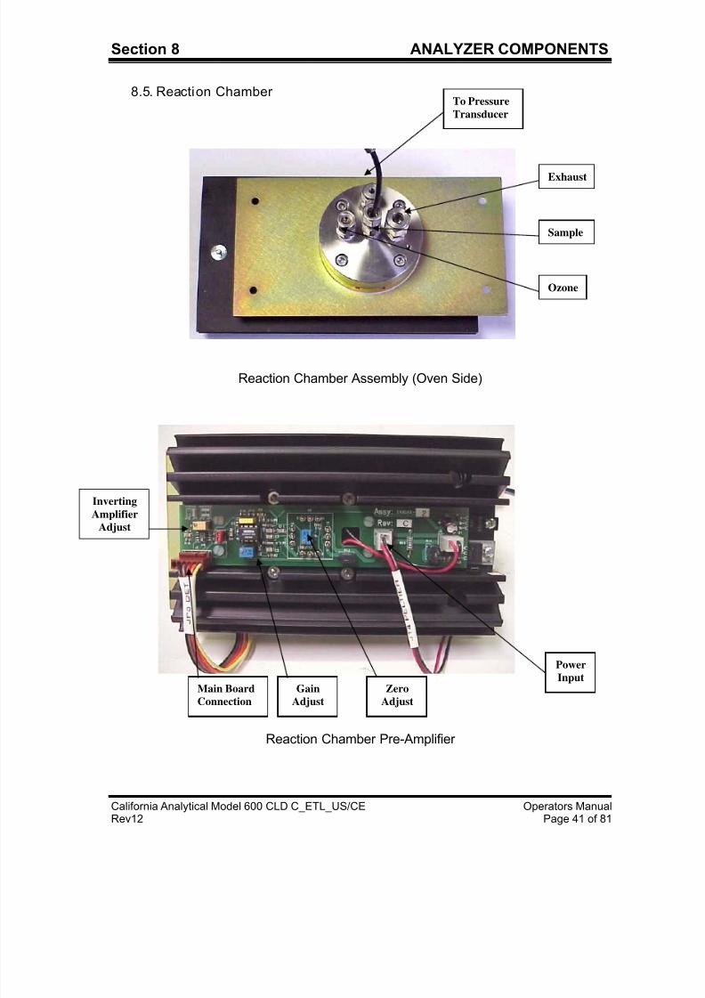
8.5. Reaction Chamber
Reaction Chamber Assembly (Oven Side)
Reaction Chamber Pre-Amplifier
Exhaust
Sample
Ozone
To Pressure
Transducer
Power
Input Zero
Adjust
Gain
Adjust
Main Board
Connection
InvertingAmplifier
Adjust
7/23/2019 600 Series Cld Ops Manual 1213
http://slidepdf.com/reader/full/600-series-cld-ops-manual-1213 51/116
Section 8 ANALYZER COMPONENTS
California Analytical Model 600 CLD C_ETL_US/CE Operators ManualRev12 Page 42 of 81
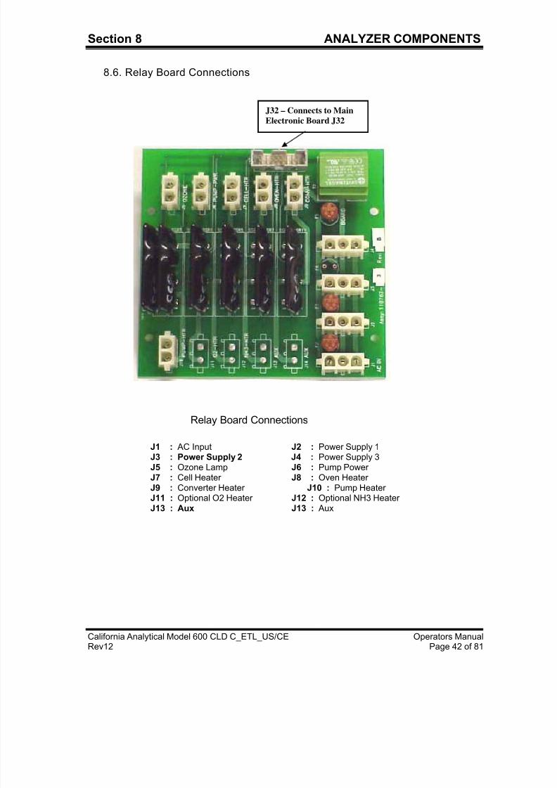
8.6. Relay Board Connections
Relay Board Connections
J1 : AC Input J2 : Power Supply 1 J3 : Power Supply 2 J4 : Power Supply 3 J5 : Ozone Lamp J6 : Pump Power J7 : Cell Heater J8 : Oven Heater J9 : Converter Heater J10 : Pump HeaterJ11 : Optional O2 Heater J12 : Optional NH3 HeaterJ13 : Aux J13 : Aux
J32 – Connects to Main
Electronic Board J32
7/23/2019 600 Series Cld Ops Manual 1213
http://slidepdf.com/reader/full/600-series-cld-ops-manual-1213 52/116
7/23/2019 600 Series Cld Ops Manual 1213
http://slidepdf.com/reader/full/600-series-cld-ops-manual-1213 53/116
Section 11 REACTION CHAMBER
California Analytical Model 600 CLD C_ETL_US/CE Operators ManualRev12 Page 44 of 81
7. Sample Pressure Check: With sample gas flowing through the instrument, check
the sample pressure setting by referring to the diagnostic screen. The sample
pressure should read as indicated in the factory pressure settings screen.
8. Sample Pump: If the analyzer is supplied with the optional internal sample pump, it
is always on in the measure mode. It is turned off during calibration and may be
manually turned off by putting the analyzer in standby.
9. Sample Line: Make certain the sample line is flushed before connecting to the
analyzer sample inlet.
10. Instrument Power : Turn instrument power on and allow the reaction chamber and
NOx converter to stabilize before turning on the sample pump and/or connecting the
sample line.
11. Sampling System: Prepare and check the sample system. Check the samplepressure as indicated in the factory settings screen.
12. Air or O2 Pressure: Check the Air/O2 pressure for proper setting as indicated in the
factory setting screen. Readjust internal pressure as required. Note: Cylinder
pressure should be set at 25 PSIG.
13. Zero & Span Calibration: Zero and span adjustment should be checked every 24
hours by either manual or automatic calibrations.
14. Reaction Chamber Assembly: Dust, water droplets, or mist entering the reaction
chamber assembly may cause drift due to contamination. If the calibration
procedures fails to bring the instrument to zero, check the chamber for contamination.
9.3. Shut Down Procedure
1. Turn off the zero, span and air/O2 cylinders.
2. If the analyzer contains the optional internal sample pump, disconnect the sample line
from the rear inlet port. Do NOT turn off the sample pump or analyzer power at this
point.
3. Allow the analyzer to draw in room air for approximately 5 minutes, or flush out anyremaining sample which may cause condensation as the analyzer cools.
4. Turn off the optional internal sample pump by setting the analyzer to standby.
5. Turn off the analyzer power.
6. Back-flush the sample line (and filter) of any sample before disconnecting and
powering down.
7/23/2019 600 Series Cld Ops Manual 1213
http://slidepdf.com/reader/full/600-series-cld-ops-manual-1213 54/116
7/23/2019 600 Series Cld Ops Manual 1213
http://slidepdf.com/reader/full/600-series-cld-ops-manual-1213 55/116
Section 11 REACTION CHAMBER
California Analytical Model 600 CLD C_ETL_US/CE Operators ManualRev12 Page 46 of 81
10.4. Main Electronics Board
The main electronics board contains the instrument power supplies and requiredinstrument electronics. A single transformer provides power to the main circuit board andincludes provisions for 110/220 VAC at 50/60 Hz input.
10.5. Relay BoardThe relay circuit board contains the logic circuitry required to control and switch the ACpower to the required heaters and sample pump.
11. Reaction Chamber
11.1. Disassembly Procedure
a. Shut off ALL gas flow.
b. Remove power from the instrument.
c. Remove the top cover retaining screws.
d. Remove all 4 tubes from the 4 way cross.
e. Remove the 4 screws securing the photodiode and reaction chamber from the oven.
f. Remove the photodiode electrical connector from the main circuit board.
g. Remove the chiller connection from the photodiode/reaction chamber.
h. Separate the photodiode and heat sink assembly from the reaction chamber byremoving the 4 Allen screws from the front of the heat sink. Save the 2 black rubber“O” rings.
i. Separate the mounting plate and the glass filter from the reaction chamber. Save the
2 Teflon spacers and “O” ring.
j. Separate the manifold from the gold reaction chamber. NOTE the position of the holesin the Teflon gasket relative to the assembly screw holes. The large hole is ozone.
11.2. Assembly Procedure
a. Wash the reaction chamber glass filter and manifold separately in detergent using atest tube brush. Be careful of the sample tube in the manifold. Do not use abrasives.
b. Dry by blowing clean with dry nitrogen.
c. Reassemble the chamber assembly in reverse order per the above. Make certain the
sample tube is centered when assembling the manifold to the reaction chamber.
7/23/2019 600 Series Cld Ops Manual 1213
http://slidepdf.com/reader/full/600-series-cld-ops-manual-1213 56/116
7/23/2019 600 Series Cld Ops Manual 1213
http://slidepdf.com/reader/full/600-series-cld-ops-manual-1213 57/116
7/23/2019 600 Series Cld Ops Manual 1213
http://slidepdf.com/reader/full/600-series-cld-ops-manual-1213 58/116
SECTION 13 APPENDIX
California Analytical Model 600 CLD C_ETL_US/CE Operators ManualMarch 2006 Page 49 of 85
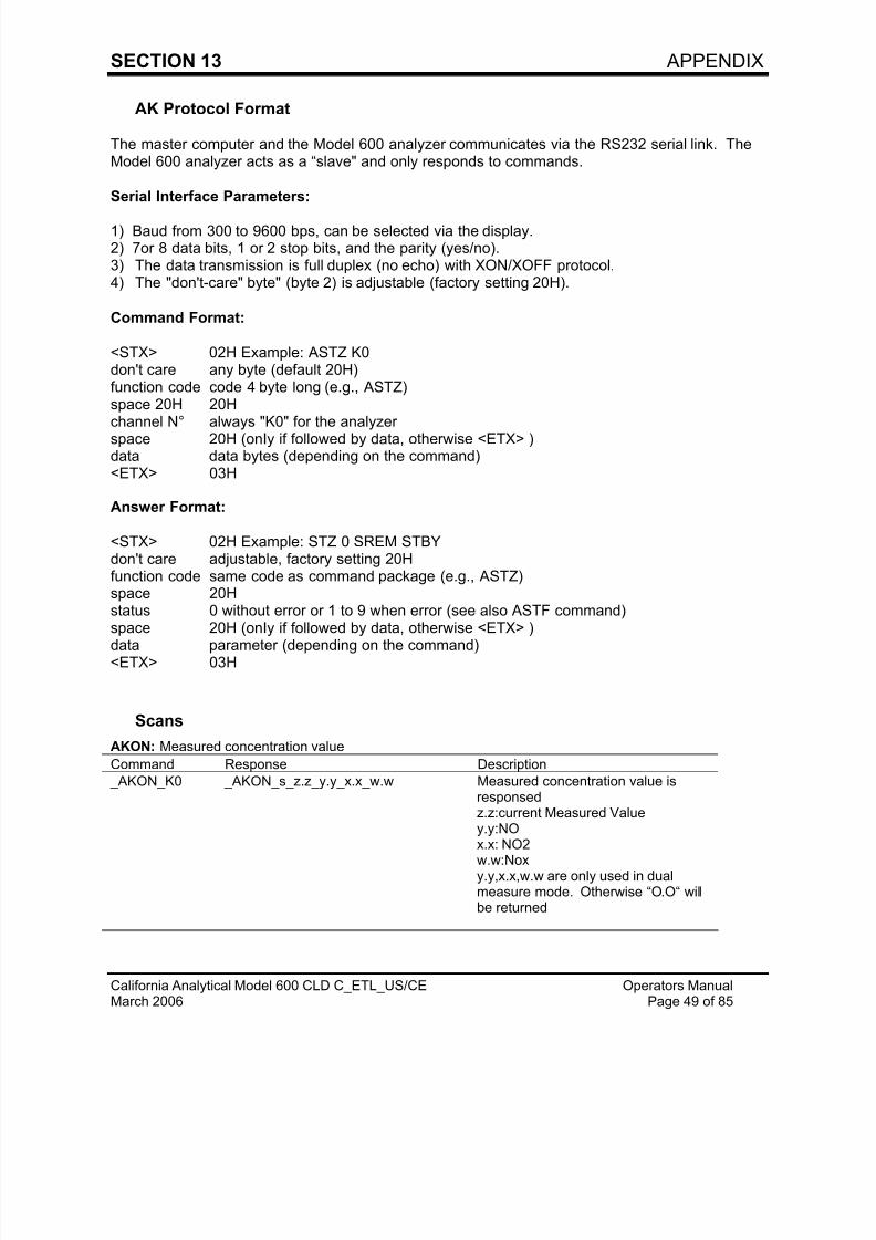
AK Protocol Format
The master computer and the Model 600 analyzer communicates via the RS232 serial link. TheModel 600 analyzer acts as a “slave" and only responds to commands.
Serial Interface Parameters:
1) Baud from 300 to 9600 bps, can be selected via the display.2) 7or 8 data bits, 1 or 2 stop bits, and the parity (yes/no).3) The data transmission is full duplex (no echo) with XON/XOFF protocol.4) The "don't-care" byte" (byte 2) is adjustable (factory setting 20H).
Command Format:
<STX> 02H Example: ASTZ K0don't care any byte (default 20H)function code code 4 byte long (e.g., ASTZ)space 20H 20H
channel N° always "K0" for the analyzerspace 20H (onIy if followed by data, otherwise <ETX> )data data bytes (depending on the command)<ETX> 03H
Answer Format:
<STX> 02H Example: STZ 0 SREM STBYdon't care adjustable, factory setting 20Hfunction code same code as command package (e.g., ASTZ)space 20Hstatus 0 without error or 1 to 9 when error (see also ASTF command)
space 20H (onIy if followed by data, otherwise <ETX> )data parameter (depending on the command)<ETX> 03H
Scans
AKON: Measured concentration value
Command Response Description
_AKON_K0 _AKON_s_z.z_y.y_x.x_w.w Measured concentration value isresponsedz.z:current Measured Valuey.y:NOx.x: NO2w.w:Noxy.y,x.x,w.w are only used in dualmeasure mode. Otherwise “O.O“ willbe returned
7/23/2019 600 Series Cld Ops Manual 1213
http://slidepdf.com/reader/full/600-series-cld-ops-manual-1213 59/116
SECTION 13 APPENDIX
California Analytical Model 600 CLD C_ETL_US/CE Operators ManualMarch 2006 Page 50 of 85
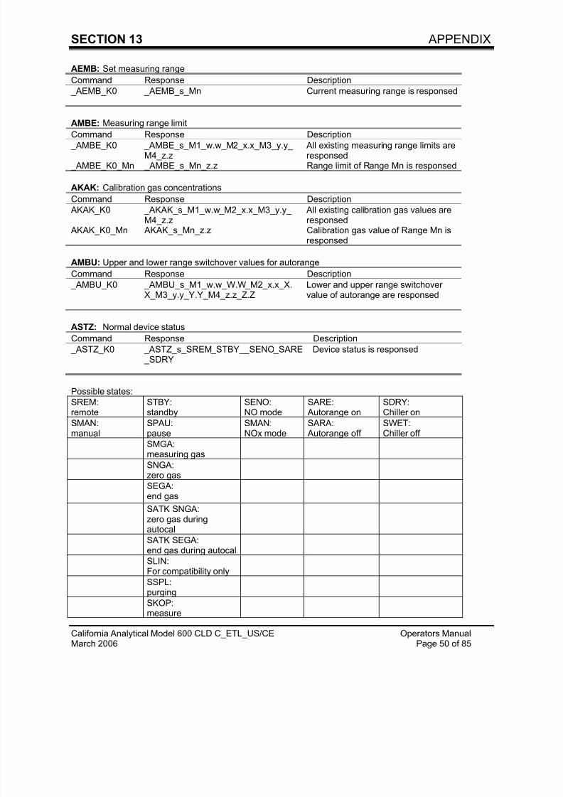
AEMB: Set measuring range
Command Response Description
_AEMB_K0 _AEMB_s_Mn Current measuring range is responsed
AMBE: Measuring range limit
Command Response Description _AMBE_K0 _AMBE_s_M1_w.w_M2_x.x_M3_y.y_
M4_z.z All existing measuring range limits areresponsed
_AMBE_K0_Mn _AMBE_s_Mn_z.z Range limit of Range Mn is responsed
AKAK: Calibration gas concentrations
Command Response Description
AKAK_K0 _AKAK_s_M1_w.w_M2_x.x_M3_y.y_ M4_z.z
All existing calibration gas values areresponsed
AKAK_K0_Mn AKAK_s_Mn_z.z Calibration gas value of Range Mn isresponsed
AMBU: Upper and lower range switchover values for autorange
Command Response Description
_AMBU_K0 _AMBU_s_M1_w.w_W.W_M2_x.x_X.X_M3_y.y_Y.Y_M4_z.z_Z.Z
Lower and upper range switchovervalue of autorange are responsed
ASTZ: Normal device status
Command Response Description
_ASTZ_K0 _ASTZ_s_SREM_STBY__SENO_SARE _SDRY
Device status is responsed
Possible states:
SREM:remote
STBY:standby
SENO:NO mode
SARE: Autorange on
SDRY:Chiller on
SMAN:manual
SPAU:pause
SMAN:NOx mode
SARA: Autorange off
SWET:Chiller off
SMGA:measuring gas
SNGA:zero gas
SEGA:end gas
SATK SNGA:zero gas duringautocal
SATK SEGA:end gas during autocal
SLIN:For compatibility only
SSPL:purging
SKOP:measure
7/23/2019 600 Series Cld Ops Manual 1213
http://slidepdf.com/reader/full/600-series-cld-ops-manual-1213 60/116
SECTION 13 APPENDIX
California Analytical Model 600 CLD C_ETL_US/CE Operators ManualMarch 2006 Page 51 of 85
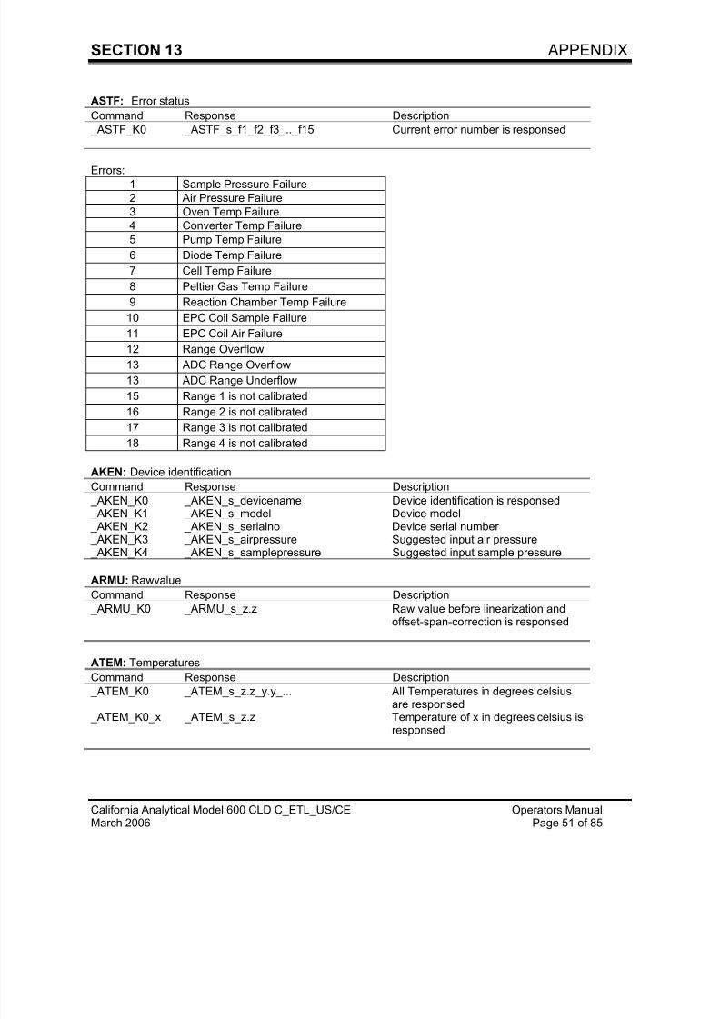
ASTF: Error status
Command Response Description
_ASTF_K0 _ ASTF_s_f1_f2_f3_.._f15 Current error number is responsed
Errors:1 Sample Pressure Failure
2 Air Pressure Failure
3 Oven Temp Failure
4 Converter Temp Failure
5 Pump Temp Failure
6 Diode Temp Failure
7 Cell Temp Failure
8 Peltier Gas Temp Failure
9 Reaction Chamber Temp Failure
10 EPC Coil Sample Failure
11 EPC Coil Air Failure
12 Range Overflow
13 ADC Range Overflow
13 ADC Range Underflow
15 Range 1 is not calibrated
16 Range 2 is not calibrated
17 Range 3 is not calibrated
18 Range 4 is not calibrated
AKEN: Device identification
Command Response Description
_ AKEN_K0 _AKEN_s_devicename Device identification is responsed
_ AKEN_K1 _AKEN_s_model Device model _ AKEN_K2 _AKEN_s_serialno Device serial number _ AKEN_K3 _AKEN_s_airpressure Suggested input air pressure _ AKEN_K4 _AKEN_s_samplepressure Suggested input sample pressure
ARMU: Rawvalue
Command Response Description
_ ARMU_K0 _ARMU_s_z.z Raw value before linearization andoffset-span-correction is responsed
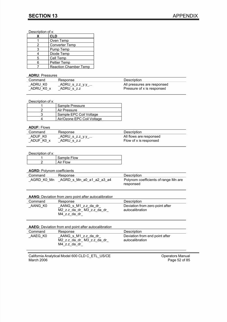
ATEM: Temperatures
Command Response Description
_ ATEM_K0 _ATEM_s_z.z_y.y_... All Temperatures in degrees celsiusare responsed
_ ATEM_K0_x _ATEM_s_z.z Temperature of x in degrees celsius isresponsed
7/23/2019 600 Series Cld Ops Manual 1213
http://slidepdf.com/reader/full/600-series-cld-ops-manual-1213 61/116
SECTION 13 APPENDIX
California Analytical Model 600 CLD C_ETL_US/CE Operators ManualMarch 2006 Page 52 of 85
Description of x:
X CLD
1 Oven Temp
2 Converter Temp
3 Pump Temp
4 Diode Temp5 Cell Temp
6 Peltier Temp
7 Reaction Chamber Temp
ADRU: Pressures
Command Response Description
_ ADRU_K0 _ADRU_s_z.z_y.y_... All pressures are responsed _ ADRU_K0_x _ADRU_s_z.z Pressure of x is responsed
Description of x:
1 Sample Pressure
2 Air Pressure
3 Sample EPC Coil Voltage
4 Air/Ozone EPC Coil Voltage
ADUF: Flows
Command Response Description
_ ADUF_K0 _ADRU_s_z.z_y.y_... All flows are responsed _ ADUF_K0_x _ADRU_s_z.z Flow of x is responsed
Description of x:
1 Sample Flow
2 Air Flow
AGRD: Polynom coefficients
Command Response Description
_ AGRD_K0_Mn _AGRD_s_Mn_a0_a1_a2_a3_a4 Polynom coefficients of range Mn areresponsed
AANG: Deviation from zero point after autocalibration
Command Response Description
_ AANG_K0 _AANG_s_M1_z.z_da_dr_M2_z.z_da_dr_ M3_z.z_da_dr_M4_z.z_da_dr_
Deviation from zero point afterautocalibration
AAEG: Deviation from end point after autocalibration
Command Response Description
_ AAEG_K0 _AANG_s_M1_z.z_da_dr_M2_z.z_da_dr_ M3_z.z_da_dr_M4_z.z_da_dr_
Deviation from end point afterautocalibration
7/23/2019 600 Series Cld Ops Manual 1213
http://slidepdf.com/reader/full/600-series-cld-ops-manual-1213 62/116
7/23/2019 600 Series Cld Ops Manual 1213
http://slidepdf.com/reader/full/600-series-cld-ops-manual-1213 63/116
SECTION 13 APPENDIX
California Analytical Model 600 CLD C_ETL_US/CE Operators ManualMarch 2006 Page 54 of 85
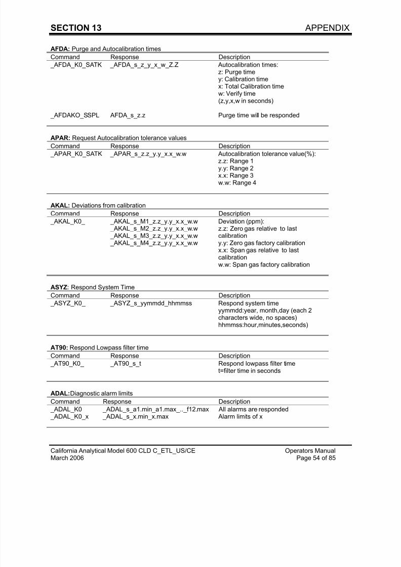
AFDA: Purge and Autocalibration times
Command Response Description
_ AFDA_K0_SATK _AFDA_s_z_y_x_w_Z.Z Autocalibration times:z: Purge timey: Calibration timex: Total Calibration time
w: Verify time(z,y,x,w in seconds)
_AFDAKO_SSPL AFDA _s_z.z Purge time will be responded
APAR: Request Autocalibration tolerance values
Command Response Description
_ APAR_K0_SATK _APAR_s_z.z_y.y_x.x_w.w Autocalibration tolerance value(%):z.z: Range 1y.y: Range 2x.x: Range 3w.w: Range 4
AKAL: Deviations from calibration
Command Response Description
_ AKAL_K0_ _AKAL_s_M1_z.z_y.y_x.x_w.w _AKAL_s_M2_z.z_y.y_x.x_w.w _AKAL_s_M3_z.z_y.y_x.x_w.w _AKAL_s_M4_z.z_y.y_x.x_w.w
Deviation (ppm):z.z: Zero gas relative to lastcalibrationy.y: Zero gas factory calibrationx.x: Span gas relative to lastcalibrationw.w: Span gas factory calibration
ASYZ: Respond System TimeCommand Response Description
_ ASYZ_K0_ _ASYZ_s_yymmdd_hhmmss Respond system timeyymmdd:year, month,day (each 2characters wide, no spaces)hhmmss:hour,minutes,seconds)
AT90: Respond Lowpass filter time
Command Response Description
_ AT90_K0_ _AT90_s_t Respond lowpass filter timet=filter time in seconds
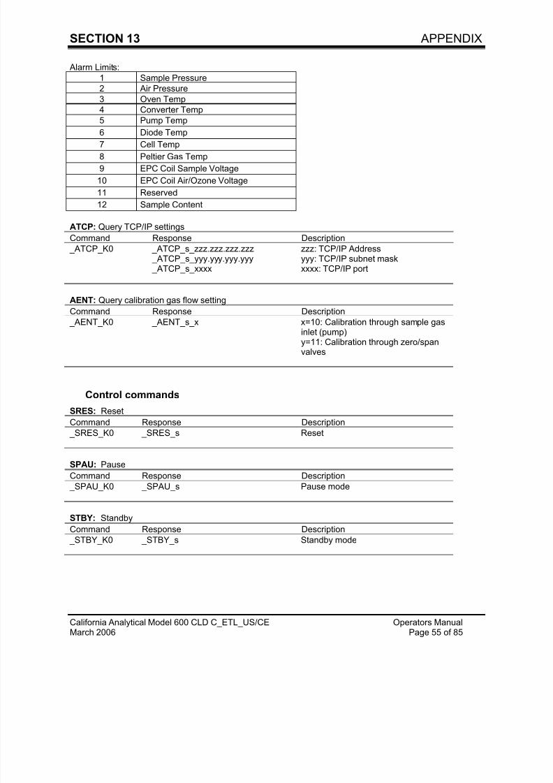
ADAL:Diagnostic alarm limits
Command Response Description
_ADAL_K0 _ ADAL_s_a1.min_a1.max_.._f12.max All alarms are responded _ADAL_K0_x _ ADAL_s_x.min_x.max Alarm limits of x
7/23/2019 600 Series Cld Ops Manual 1213
http://slidepdf.com/reader/full/600-series-cld-ops-manual-1213 64/116
SECTION 13 APPENDIX
California Analytical Model 600 CLD C_ETL_US/CE Operators ManualMarch 2006 Page 55 of 85
Alarm Limits:
1 Sample Pressure
2 Air Pressure
3 Oven Temp
4 Converter Temp
5 Pump Temp
6 Diode Temp7 Cell Temp
8 Peltier Gas Temp
9 EPC Coil Sample Voltage
10 EPC Coil Air/Ozone Voltage
11 Reserved
12 Sample Content
ATCP: Query TCP/IP settings
Command Response Description
_ ATCP_K0 _ATCP_s_zzz.zzz.zzz.zzz _ATCP_s_yyy.yyy.yyy.yyy _ATCP_s_xxxx
zzz: TCP/IP Addressyyy: TCP/IP subnet maskxxxx: TCP/IP port
AENT: Query calibration gas flow setting
Command Response Description
_ AENT_K0 _AENT_s_x x=10: Calibration through sample gasinlet (pump)y=11: Calibration through zero/spanvalves
Control commandsSRES: Reset
Command Response Description
_ SRES_K0 _SRES_s Reset
SPAU: Pause
Command Response Description
_ SPAU_K0 _SPAU_s Pause mode
STBY: Standby
Command Response Description _ STBY_K0 _STBY_s Standby mode
7/23/2019 600 Series Cld Ops Manual 1213
http://slidepdf.com/reader/full/600-series-cld-ops-manual-1213 65/116
SECTION 13 APPENDIX
California Analytical Model 600 CLD C_ETL_US/CE Operators ManualMarch 2006 Page 56 of 85
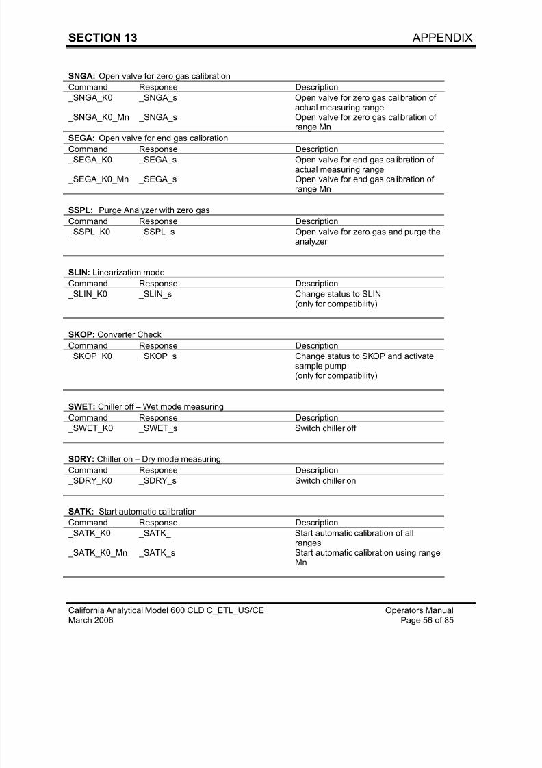
SNGA: Open valve for zero gas calibration
Command Response Description
_SNGA_K0 _SNGA_s Open valve for zero gas calibration ofactual measuring range
_SNGA_K0_Mn _SNGA_s Open valve for zero gas calibration of
range MnSEGA: Open valve for end gas calibration
Command Response Description
_SEGA_K0 _SEGA_s Open valve for end gas calibration ofactual measuring range
_SEGA_K0_Mn _SEGA_s Open valve for end gas calibration ofrange Mn
SSPL: Purge Analyzer with zero gas
Command Response Description
_SSPL_K0 _SSPL_s Open valve for zero gas and purge theanalyzer
SLIN: Linearization mode
Command Response Description
_SLIN_K0 _SLIN_s Change status to SLIN(only for compatibility)
SKOP: Converter Check
Command Response Description
_SKOP_K0 _SKOP_s Change status to SKOP and activatesample pump(only for compatibility)
SWET: Chiller off – Wet mode measuring
Command Response Description
_SWET_K0 _SWET_s Switch chiller off
SDRY: Chiller on – Dry mode measuring
Command Response Description
_SDRY_K0 _SDRY_s Switch chiller on
SATK: Start automatic calibration
Command Response Description
_SATK_K0 _SATK_ Start automatic calibration of allranges
_SATK_K0_Mn _SATK_s Start automatic calibration using rangeMn
7/23/2019 600 Series Cld Ops Manual 1213
http://slidepdf.com/reader/full/600-series-cld-ops-manual-1213 66/116
SECTION 13 APPENDIX
California Analytical Model 600 CLD C_ETL_US/CE Operators ManualMarch 2006 Page 57 of 85
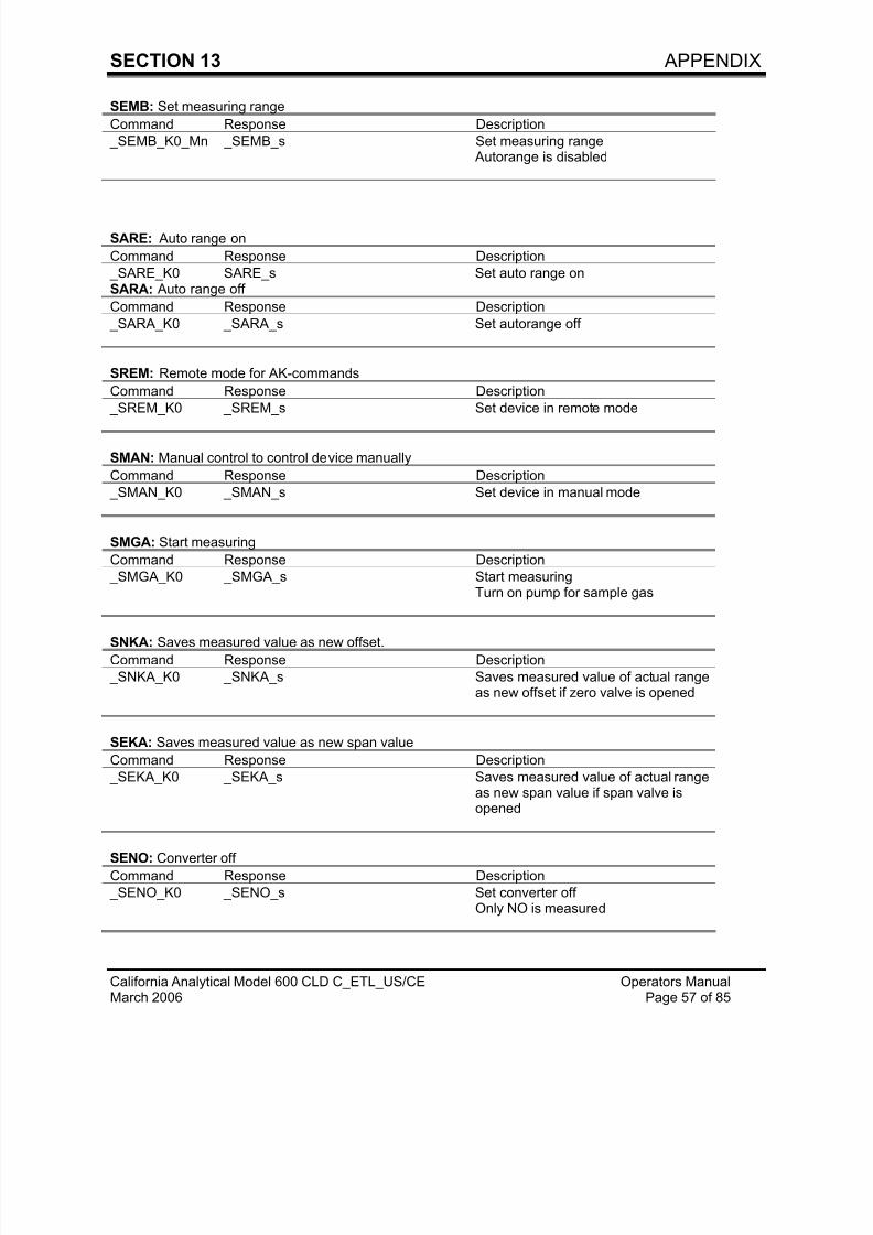
SEMB: Set measuring range
Command Response Description
_SEMB_K0_Mn _SEMB_s Set measuring range Autorange is disabled
SARE: Auto range on
Command Response Description
_SARE_K0 SARE_s Set auto range onSARA: Auto range off
Command Response Description
_SARA_K0 _SARA_s Set autorange off
SREM: Remote mode for AK-commands
Command Response Description
_SREM_K0 _SREM_s Set device in remote mode
SMAN: Manual control to control device manually
Command Response Description
_SMAN_K0 _SMAN_s Set device in manual mode
SMGA: Start measuring
Command Response Description
_SMGA_K0 _SMGA_s Start measuringTurn on pump for sample gas
SNKA: Saves measured value as new offset.
Command Response Description
_SNKA_K0 _SNKA_s Saves measured value of actual rangeas new offset if zero valve is opened
SEKA: Saves measured value as new span value
Command Response Description
_SEKA_K0 _SEKA_s Saves measured value of actual rangeas new span value if span valve isopened
SENO: Converter off
Command Response Description
_SENO_K0 _SENO_s Set converter offOnly NO is measured
7/23/2019 600 Series Cld Ops Manual 1213
http://slidepdf.com/reader/full/600-series-cld-ops-manual-1213 67/116
SECTION 13 APPENDIX
California Analytical Model 600 CLD C_ETL_US/CE Operators ManualMarch 2006 Page 58 of 85
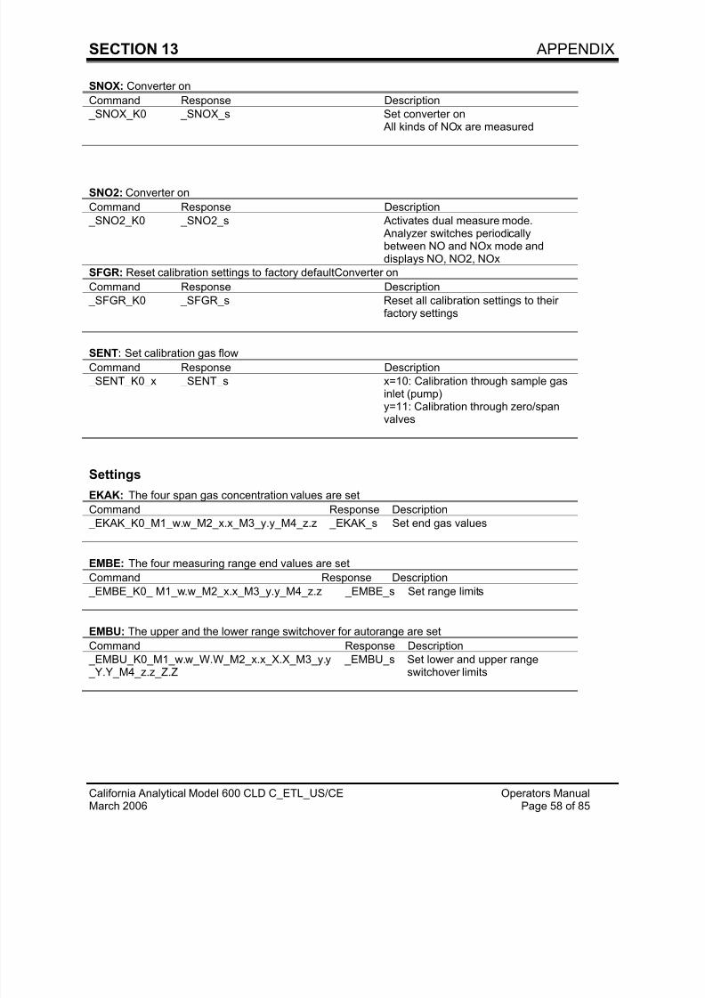
SNOX: Converter on
Command Response Description
_SNOX_K0 _SNOX_s Set converter on All kinds of NOx are measured
SNO2: Converter on
Command Response Description
_SNO2_K0 _SNO2_s Activates dual measure mode. Analyzer switches periodicallybetween NO and NOx mode anddisplays NO, NO2, NOx
SFGR: Reset calibration settings to factory defaultConverter on
Command Response Description
_SFGR_K0 _SFGR_s Reset all calibration settings to theirfactory settings
SENT: Set calibration gas flow
Command Response Description
_SENT_K0_x _SENT_s x=10: Calibration through sample gasinlet (pump)y=11: Calibration through zero/spanvalves
Settings
EKAK: The four span gas concentration values are set
Command Response Description
_EKAK_K0_M1_w.w_M2_x.x_M3_y.y_M4_z.z _EKAK_s Set end gas values
EMBE: The four measuring range end values are set
Command Response Description
_EMBE_K0_ M1_w.w_M2_x.x_M3_y.y_M4_z.z _EMBE_s Set range limits
EMBU: The upper and the lower range switchover for autorange are set
Command Response Description
_EMBU_K0_M1_w.w_W.W_M2_x.x_X.X_M3_y.y
_Y.Y_M4_z.z_Z.Z
_EMBU_s Set lower and upper range
switchover limits
7/23/2019 600 Series Cld Ops Manual 1213
http://slidepdf.com/reader/full/600-series-cld-ops-manual-1213 68/116
SECTION 13 APPENDIX
California Analytical Model 600 CLD C_ETL_US/CE Operators ManualMarch 2006 Page 59 of 85
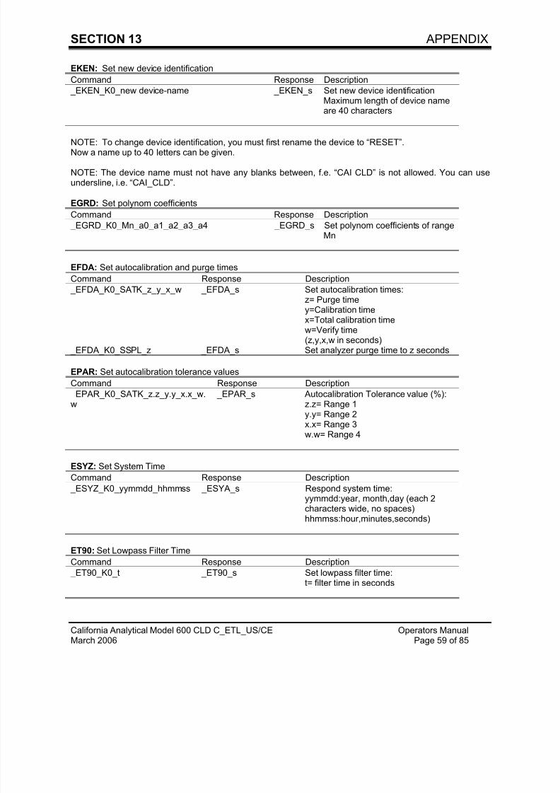
EKEN: Set new device identification
Command Response Description
_EKEN_K0_new device-name _EKEN_s Set new device identificationMaximum length of device nameare 40 characters
NOTE: To change device identification, you must first rename the device to “RESET”.Now a name up to 40 letters can be given.
NOTE: The device name must not have any blanks between, f.e. “CAI CLD” is not allowed. You can useundersline, i.e. “CAI_CLD”.
EGRD: Set polynom coefficients
Command Response Description
_EGRD_K0_Mn_a0_a1_a2_a3_a4 _EGRD_s Set polynom coefficients of rangeMn
EFDA: Set autocalibration and purge timesCommand Response Description
_ EFDA_K0_SATK_z_y_x_w _EFDA_s Set autocalibration times:z= Purge timey=Calibration timex=Total calibration timew=Verify time(z,y,x,w in seconds)
_ EFDA_K0_SSPL_z _EFDA_s Set analyzer purge time to z seconds
EPAR: Set autocalibration tolerance values
Command Response Description
_ EPAR_K0_SATK_z.z_y.y_x.x_w.
w
_EPAR_s Autocalibration Tolerance value (%):
z.z= Range 1y.y= Range 2x.x= Range 3w.w= Range 4
ESYZ: Set System Time
Command Response Description
_ ESYZ_K0_yymmdd_hhmmss _ESYA_s Respond system time:yymmdd:year, month,day (each 2characters wide, no spaces)hhmmss:hour,minutes,seconds)
ET90: Set Lowpass Filter Time
Command Response Description
_ ET90_K0_t _ET90_s Set lowpass filter time:t= filter time in seconds
7/23/2019 600 Series Cld Ops Manual 1213
http://slidepdf.com/reader/full/600-series-cld-ops-manual-1213 69/116
SECTION 13 APPENDIX
California Analytical Model 600 CLD C_ETL_US/CE Operators ManualMarch 2006 Page 60 of 85
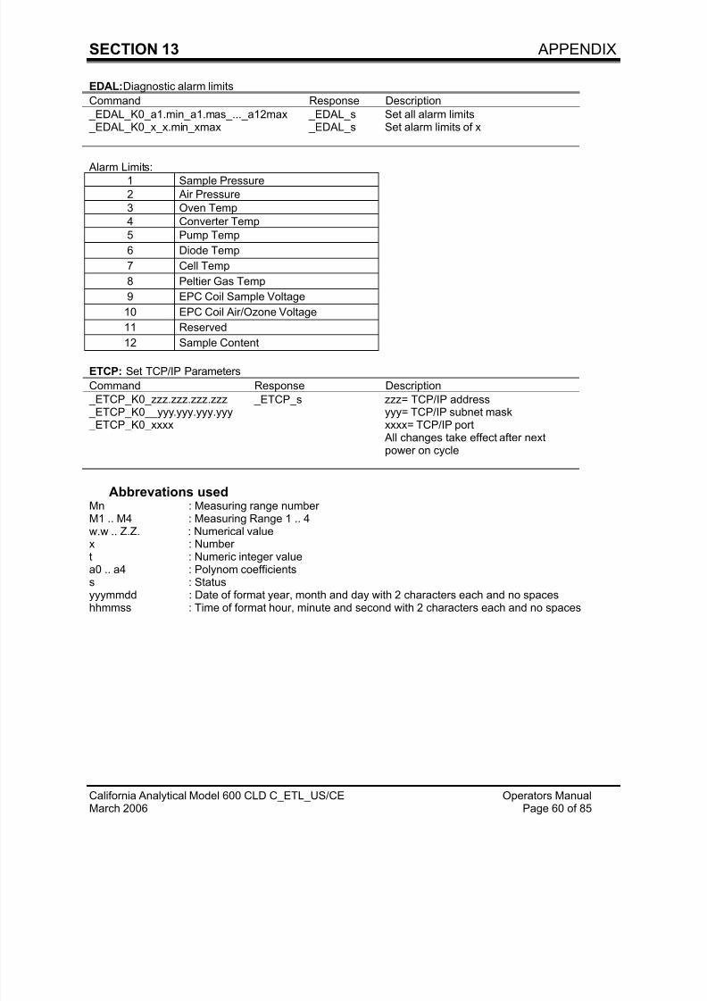
EDAL:Diagnostic alarm limits
Command Response Description
_EDAL_K0_a1.min_a1.mas_..._a12max _ EDAL_s Set all alarm limits _EDAL_K0_x_x.min_xmax _ EDAL_s Set alarm limits of x
Alarm Limits:1 Sample Pressure
2 Air Pressure
3 Oven Temp
4 Converter Temp
5 Pump Temp
6 Diode Temp
7 Cell Temp
8 Peltier Gas Temp
9 EPC Coil Sample Voltage
10 EPC Coil Air/Ozone Voltage
11 Reserved
12 Sample Content
ETCP: Set TCP/IP Parameters
Command Response Description
_ETCP_K0_zzz.zzz.zzz.zzz _ETCP_K0__yyy.yyy.yyy.yyy _ETCP_K0_xxxx
_ETCP_s zzz= TCP/IP addressyyy= TCP/IP subnet maskxxxx= TCP/IP port
All changes take effect after nextpower on cycle
Abbrevations used
Mn : Measuring range numberM1 .. M4 : Measuring Range 1 .. 4w.w .. Z.Z. : Numerical valuex : Numbert : Numeric integer valuea0 .. a4 : Polynom coefficientss : Statusyyymmdd : Date of format year, month and day with 2 characters each and no spaceshhmmss : Time of format hour, minute and second with 2 characters each and no spaces
7/23/2019 600 Series Cld Ops Manual 1213
http://slidepdf.com/reader/full/600-series-cld-ops-manual-1213 70/116
SECTION 13 APPENDIX
California Analytical Model 600 CLD C_ETL_US/CE Operators ManualMarch 2006 Page 61 of 85
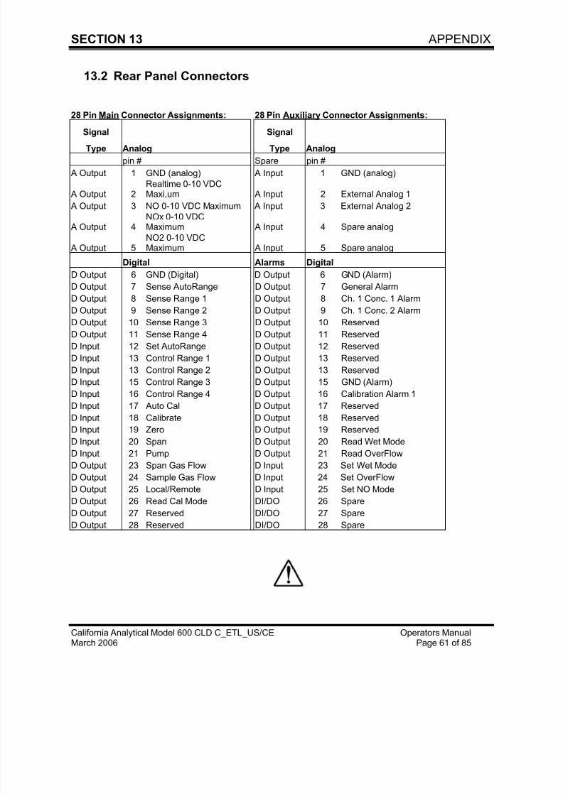
13.2 Rear Panel Connectors
28 Pin Main Connector Assignments: 28 Pin Auxiliary Connector Assignments:
Signal Signal
Type Analog Type Analog
pin # Spare pin #
A Output 1 GND (analog) A Input 1 GND (analog)
A Output 2Realtime 0-10 VDCMaxi,um A Input 2 External Analog 1
A Output 3 NO 0-10 VDC Maximum A Input 3 External Analog 2
A Output 4NOx 0-10 VDCMaximum A Input 4 Spare analog
A Output 5NO2 0-10 VDCMaximum A Input 5 Spare analog
Digital Alarms Digital D Output 6 GND (Digital) D Output 6 GND (Alarm)
D Output 7 Sense AutoRange D Output 7 General Alarm
D Output 8 Sense Range 1 D Output 8 Ch. 1 Conc. 1 Alarm
D Output 9 Sense Range 2 D Output 9 Ch. 1 Conc. 2 Alarm
D Output 10 Sense Range 3 D Output 10 Reserved
D Output 11 Sense Range 4 D Output 11 Reserved
D Input 12 Set AutoRange D Output 12 Reserved
D Input 13 Control Range 1 D Output 13 Reserved
D Input 13 Control Range 2 D Output 13 Reserved
D Input 15 Control Range 3 D Output 15 GND (Alarm)
D Input 16 Control Range 4 D Output 16 Calibration Alarm 1
D Input 17 Auto Cal D Output 17 Reserved
D Input 18 Calibrate D Output 18 Reserved
D Input 19 Zero D Output 19 Reserved
D Input 20 Span D Output 20 Read Wet Mode
D Input 21 Pump D Output 21 Read OverFlow
D Output 23 Span Gas Flow D Input 23 Set Wet Mode
D Output 24 Sample Gas Flow D Input 24 Set OverFlow
D Output 25 Local/Remote D Input 25 Set NO Mode
D Output 26 Read Cal Mode DI/DO 26 Spare
D Output 27 Reserved DI/DO 27 Spare
D Output 28 Reserved DI/DO 28 Spare
7/23/2019 600 Series Cld Ops Manual 1213
http://slidepdf.com/reader/full/600-series-cld-ops-manual-1213 71/116
7/23/2019 600 Series Cld Ops Manual 1213
http://slidepdf.com/reader/full/600-series-cld-ops-manual-1213 72/116
SECTION 13 APPENDIX
California Analytical Model 600 CLD C_ETL_US/CE Operators ManualMarch 2006 Page 63 of 85
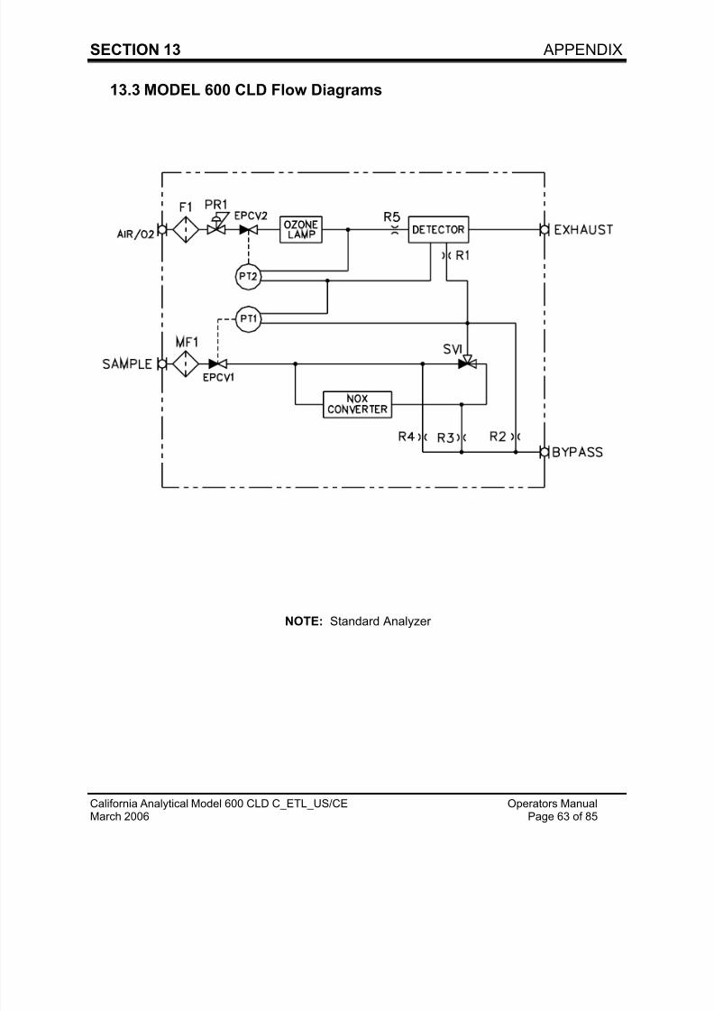
13.3 MODEL 600 CLD Flow Diagrams
NOTE: Standard Analyzer
7/23/2019 600 Series Cld Ops Manual 1213
http://slidepdf.com/reader/full/600-series-cld-ops-manual-1213 73/116
SECTION 13 APPENDIX
California Analytical Model 600 CLD C_ETL_US/CE Operators ManualMarch 2006 Page 64 of 85
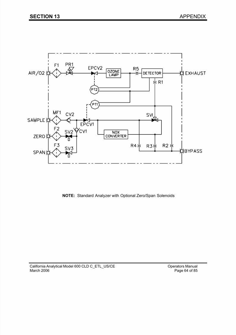
NOTE: Standard Analyzer with Optional Zero/Span Solenoids
7/23/2019 600 Series Cld Ops Manual 1213
http://slidepdf.com/reader/full/600-series-cld-ops-manual-1213 74/116
SECTION 13 APPENDIX
California Analytical Model 600 CLD C_ETL_US/CE Operators ManualMarch 2006 Page 65 of 85
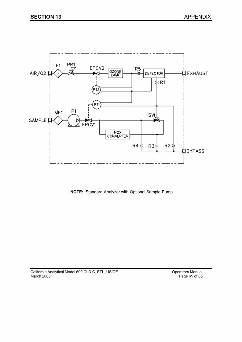
NOTE: Standard Analyzer with Optional Sample Pump
7/23/2019 600 Series Cld Ops Manual 1213
http://slidepdf.com/reader/full/600-series-cld-ops-manual-1213 75/116
SECTION 13 APPENDIX
California Analytical Model 600 CLD C_ETL_US/CE Operators ManualMarch 2006 Page 66 of 85
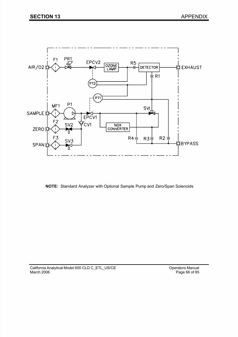
NOTE: Standard Analyzer with Optional Sample Pump and Zero/Span Solenoids
7/23/2019 600 Series Cld Ops Manual 1213
http://slidepdf.com/reader/full/600-series-cld-ops-manual-1213 76/116
SECTION 13 APPENDIX
California Analytical Model 600 CLD C_ETL_US/CE Operators ManualMarch 2006 Page 67 of 85
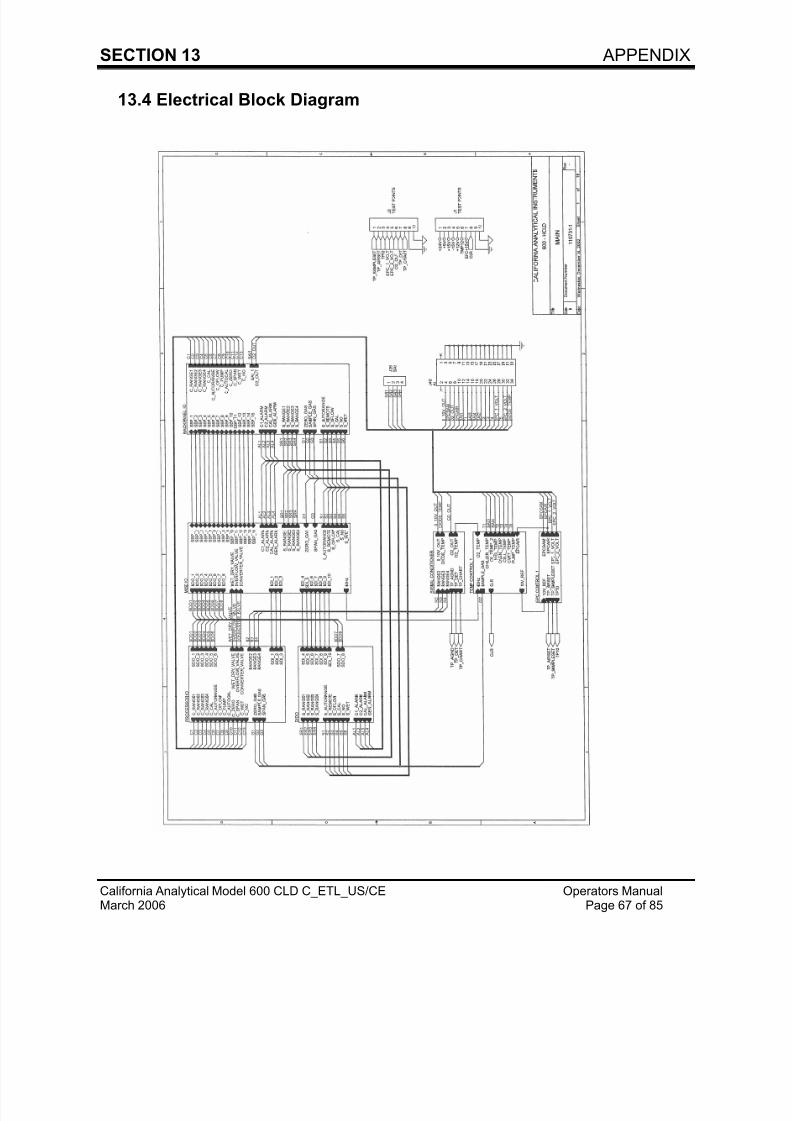
13.4 Electrical Block Diagram
7/23/2019 600 Series Cld Ops Manual 1213
http://slidepdf.com/reader/full/600-series-cld-ops-manual-1213 77/116
7/23/2019 600 Series Cld Ops Manual 1213
http://slidepdf.com/reader/full/600-series-cld-ops-manual-1213 78/116
SECTION 13 APPENDIX
California Analytical Model 600 CLD C_ETL_US/CE Operators ManualMarch 2006 Page 69 of 85
2.0 OPERATION OF MEASUREMENT KEYSNote: The & Keys continue to be used to view a complete list of menu items.
2.1 Over range 888888In the Sampling mode only, any value that exceeds the “software range” by
more than10% will be displayed as 888888.
Note: If the ranges have not been modified then the original factory physical rangesand the software ranges are the same.
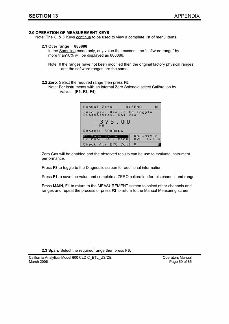
2.2 Zero: Select the required range then press F5.Note: For instruments with an internal Zero Solenoid select Calibration by
Valves. (F5, F2, F4)
Zero Gas will be enabled and the observed results can be use to evaluate instrumentperformance.
Press F3 to toggle to the Diagnostic screen for additional information
Press F1 to save the value and complete a ZERO calibration for this channel and range
Press MAIN, F1 to return to the MEASUREMENT screen to select other channels and
ranges and repeat the process or press F2 to return to the Manual Measuring screen
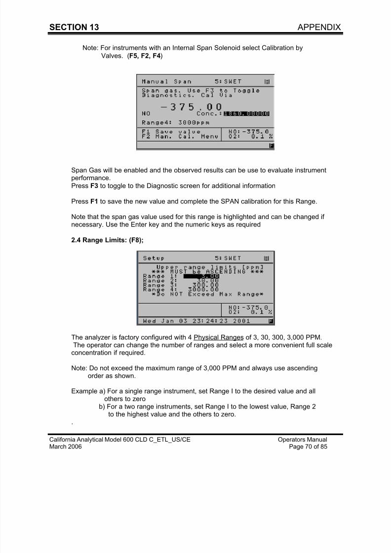
2.3 Span: Select the required range then press F6.
7/23/2019 600 Series Cld Ops Manual 1213
http://slidepdf.com/reader/full/600-series-cld-ops-manual-1213 79/116
7/23/2019 600 Series Cld Ops Manual 1213
http://slidepdf.com/reader/full/600-series-cld-ops-manual-1213 80/116
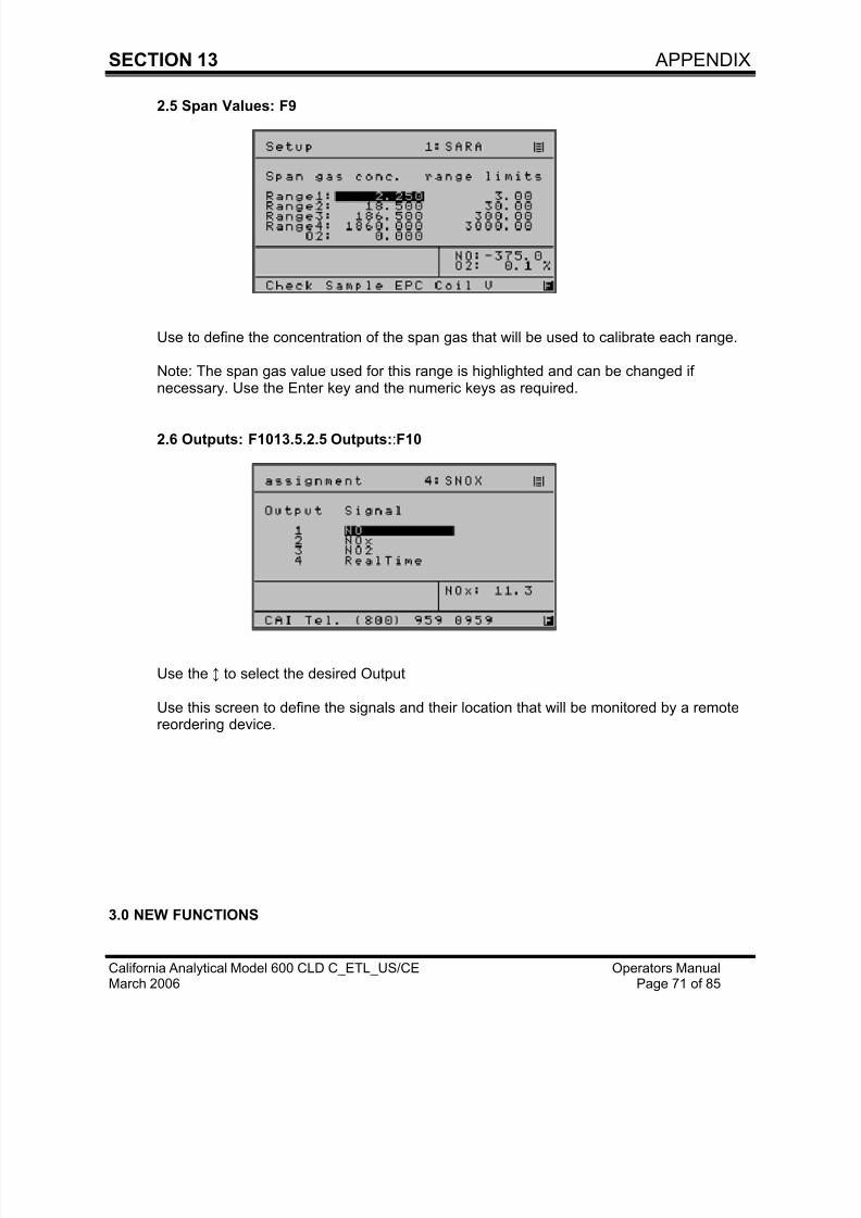
7/23/2019 600 Series Cld Ops Manual 1213
http://slidepdf.com/reader/full/600-series-cld-ops-manual-1213 81/116
SECTION 13 APPENDIX
California Analytical Model 600 CLD C_ETL_US/CE Operators ManualMarch 2006 Page 72 of 85
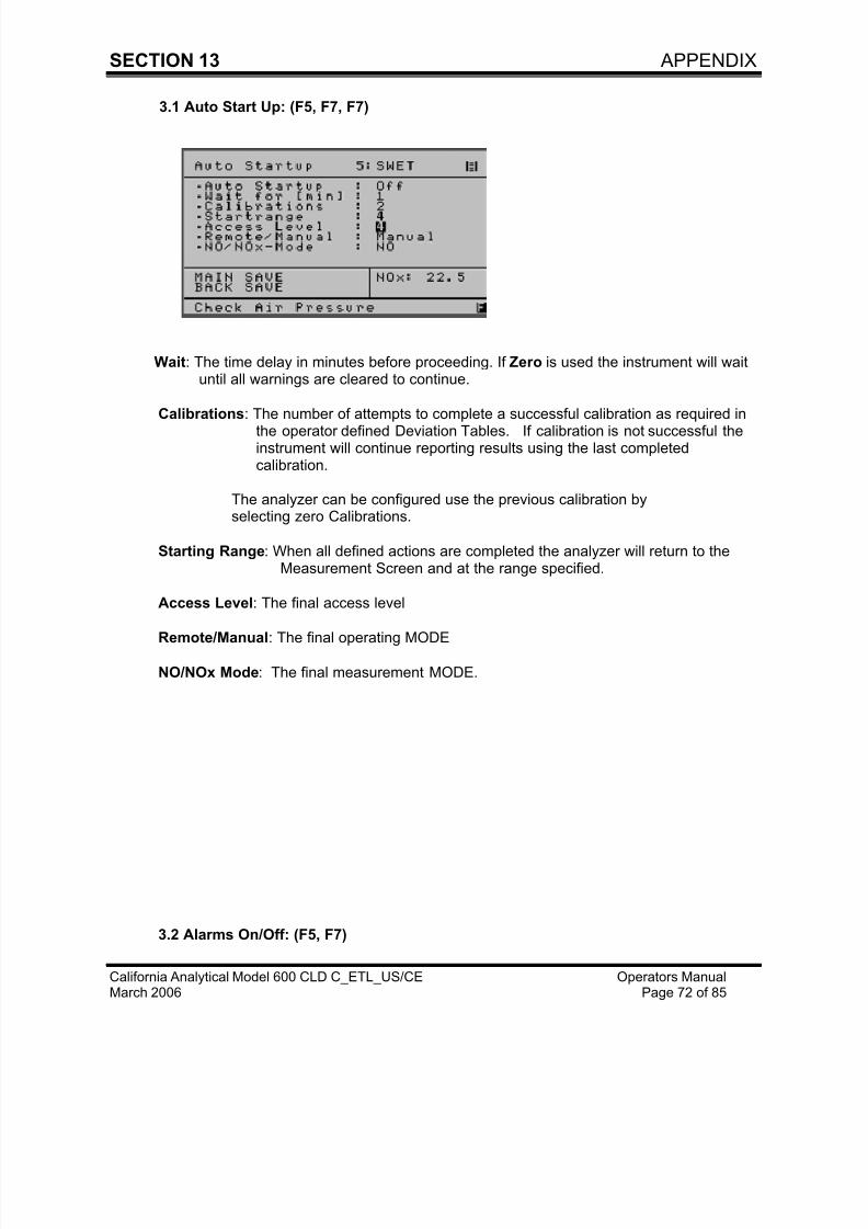
3.1 Auto Start Up: (F5, F7, F7)
Wait: The time delay in minutes before proceeding. If Zero is used the instrument will waituntil all warnings are cleared to continue.
Calibrations: The number of attempts to complete a successful calibration as required inthe operator defined Deviation Tables. If calibration is not successful theinstrument will continue reporting results using the last completedcalibration.
The analyzer can be configured use the previous calibration byselecting zero Calibrations.
Starting Range: When all defined actions are completed the analyzer will return to theMeasurement Screen and at the range specified.
Access Level: The final access level
Remote/Manual: The final operating MODE
NO/NOx Mode: The final measurement MODE.
3.2 Alarms On/Off: (F5, F7)
7/23/2019 600 Series Cld Ops Manual 1213
http://slidepdf.com/reader/full/600-series-cld-ops-manual-1213 82/116
SECTION 13 APPENDIX
California Analytical Model 600 CLD C_ETL_US/CE Operators ManualMarch 2006 Page 73 of 85
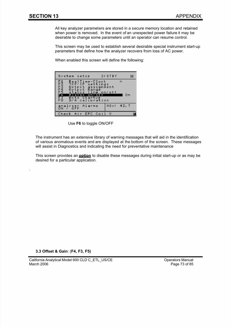
All key analyzer parameters are stored in a secure memory location and retainedwhen power is removed. In the event of an unexpected power failure it may bedesirable to change some parameters until an operator can resume control.
This screen may be used to establish several desirable special instrument start-upparameters that define how the analyzer recovers from loss of AC power.
When enabled this screen will define the following:
Use F6 to toggle ON/OFF
The instrument has an extensive library of warning messages that will aid in the identificationof various anomalous events and are displayed at the bottom of the screen. These messageswill assist in Diagnostics and indicating the need for preventative maintenance
This screen provides an option to disable these messages during initial start-up or as may bedesired for a particular application.
.
3.3 Offset & Gain: (F4, F3, F5)
7/23/2019 600 Series Cld Ops Manual 1213
http://slidepdf.com/reader/full/600-series-cld-ops-manual-1213 83/116
7/23/2019 600 Series Cld Ops Manual 1213
http://slidepdf.com/reader/full/600-series-cld-ops-manual-1213 84/116
SECTION 13 APPENDIX
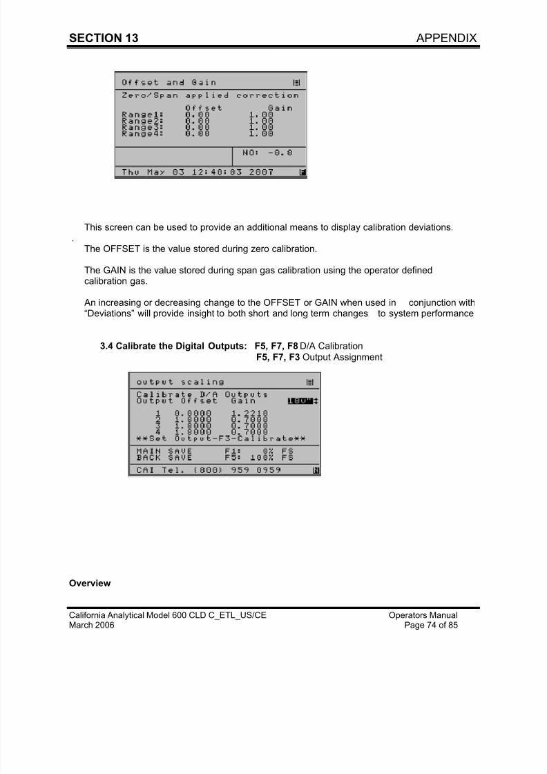
California Analytical Model 600 CLD C_ETL_US/CE Operators ManualMarch 2006 Page 75 of 85
The 600 CLD Series is designed to provide three analog outputs that can be configured as 0-10v,4-20 ma, or 0-20 ma. With this version the outputs can also be configured to include an additional
1.0 volt and 5.0 volt output and a calibration capability.
The instrument can be configured to provide either voltage or current signals.
This screen is used to select the scaling of the current (ma) or voltage(1,5,10) range that isrequired by a remote recording device. The outputs can be calibrated to exactly match the resultsobtained on a PLC, Recorder, Data Logger or other remote recording device that may beconnected to the analyzer.
The operator will first select the OUTPUT ASSIGNMENT screen and choose the output that is setto be calibrated. All outputs of interest may be selected. When calibration is competed, theoperator will return the outputs to their original assignment.
The D-A CALIBRATION screen will be then be used to complete the calibration procedure.This screen provides a section that is used to record the zero signal corrections (zero offset) and asecond area to record the 100% signal corrections (Gain) for each of the four output signals that
may be defined to develop a voltage or current signal. Since this is a Digital to Analog conversion,the calibration will require the completion of a simple “trial and error” procedure. The operator willobserve the results of a “zero or full scale (Gain) signal generated by the analyzer to the remoterecording device and select a correction factor. The operator will save this value and thenobserve the results on the attached remote recording device.
The process of selection and saving for “zero” and “span” will be repeated until a satisfactorycalibration is achieved. For 0-1V, 0-5V, 0-10V and a 0-20 ma outputs the Offset and Gain valuesare independent and do not interact. With the 4-20 ma output, the “Offset (zero)” and “Gain(span)” values interact and may require a few more trials.
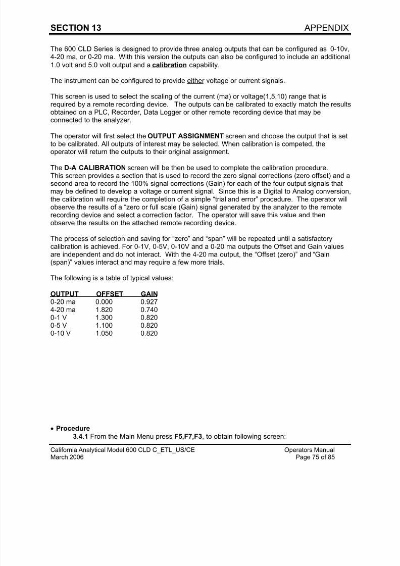
The following is a table of typical values:
OUTPUT OFFSET GAIN 0-20 ma 0.000 0.9274-20 ma 1.820 0.7400-1 V 1.300 0.8200-5 V 1.100 0.8200-10 V 1.050 0.820
• Procedure
3.4.1 From the Main Menu press F5,F7,F3, to obtain following screen:
7/23/2019 600 Series Cld Ops Manual 1213
http://slidepdf.com/reader/full/600-series-cld-ops-manual-1213 85/116
SECTION 13 APPENDIX
California Analytical Model 600 CLD C_ETL_US/CE Operators ManualMarch 2006 Page 76 of 85
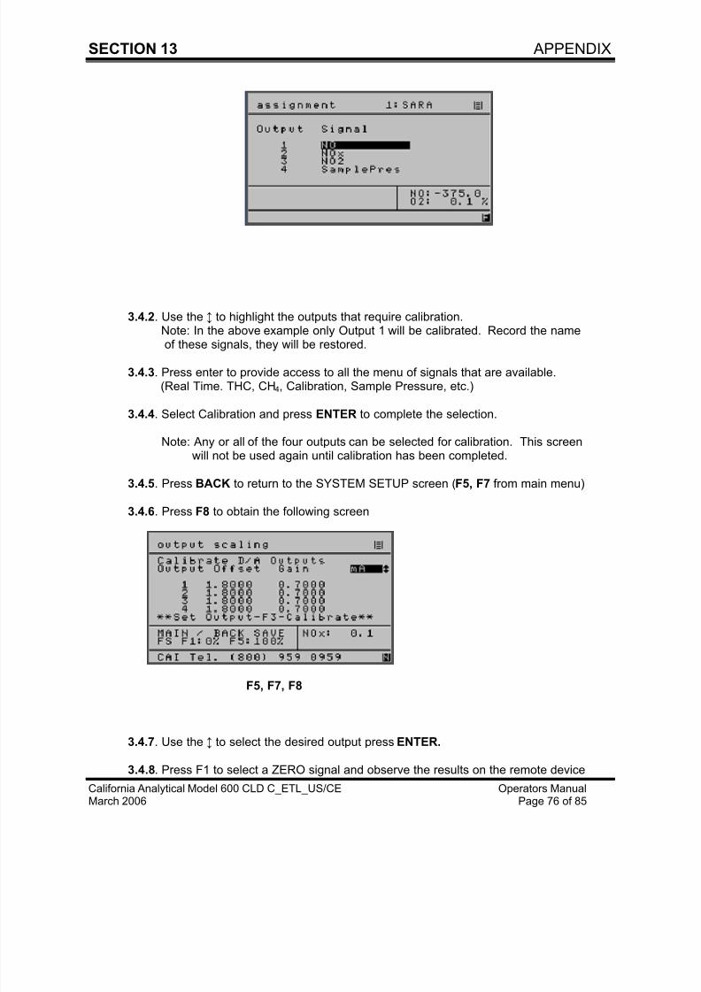
3.4.2. Use the ↕ to highlight the outputs that require calibration.
Note: In the above example only Output 1 will be calibrated. Record the nameof these signals, they will be restored.
3.4.3. Press enter to provide access to all the menu of signals that are available.(Real Time. THC, CH4, Calibration, Sample Pressure, etc.)
3.4.4. Select Calibration and press ENTER to complete the selection.
Note: Any or all of the four outputs can be selected for calibration. This screenwill not be used again until calibration has been completed.
3.4.5. Press BACK to return to the SYSTEM SETUP screen (F5, F7 from main menu)
3.4.6. Press F8 to obtain the following screen
F5, F7, F8
3.4.7. Use the ↕ to select the desired output press ENTER.
3.4.8. Press F1 to select a ZERO signal and observe the results on the remote device
7/23/2019 600 Series Cld Ops Manual 1213
http://slidepdf.com/reader/full/600-series-cld-ops-manual-1213 86/116
SECTION 13 APPENDIX
California Analytical Model 600 CLD C_ETL_US/CE Operators ManualMarch 2006 Page 77 of 85
3.4.9. Change the offset value press BACK to save the new value.
3.4.10. Press F8 to return to the D-A Calibration screen and note the results on theremote device.
3.4.11. Repeat steps 8.0 thru 10.0 until a satisfactory ZERO calibration is achieved.
3.4.12. Complete steps 8.0 thru 10.0 for each of the remaining outputs that requirecalibration.
3.4.13. Press F5 to produce a full scale (100%) signal.
3.4.14. Use the arrow keys to position the curser at the require GAIN value.
3.4.15. Observe the results on the remote device and make a correction to the GAIN
value for the output of interest. Press BACK to save this new value
3.4.16. Press F8 to return to the D-A calibration screen
3.4.17. Observe the results on the remote device and repeat the steps to change theGAIN value by repeating steps 14.0 thru 16.0 as needed for each output.
3.4.18. Return to the OUTPUT Assignment screen F5, F7, F3 from the main menuand change the output signals from CALIBRATE to their original values as
defined in step 3.4.2.
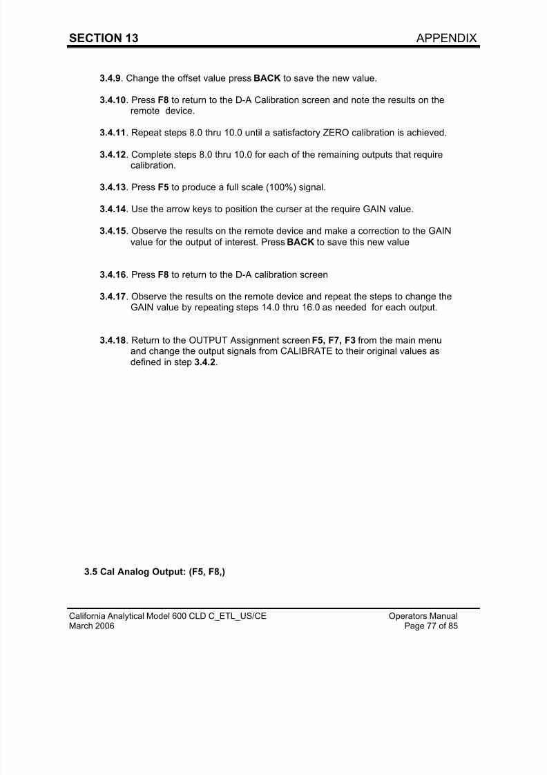
3.5 Cal Analog Output: (F5, F8,)
7/23/2019 600 Series Cld Ops Manual 1213
http://slidepdf.com/reader/full/600-series-cld-ops-manual-1213 87/116
SECTION 13 APPENDIX
California Analytical Model 600 CLD C_ETL_US/CE Operators ManualMarch 2006 Page 78 of 85
Use F8 to toggle on/off
This will provide improved versatility and control of the NO and NOx output signals. When NO orNOx are assigned to specific outputs. The CAL ANALOG output can be enabled by the operatorand the MODE selected at the Measuring Screen will be impressed at the selected output.
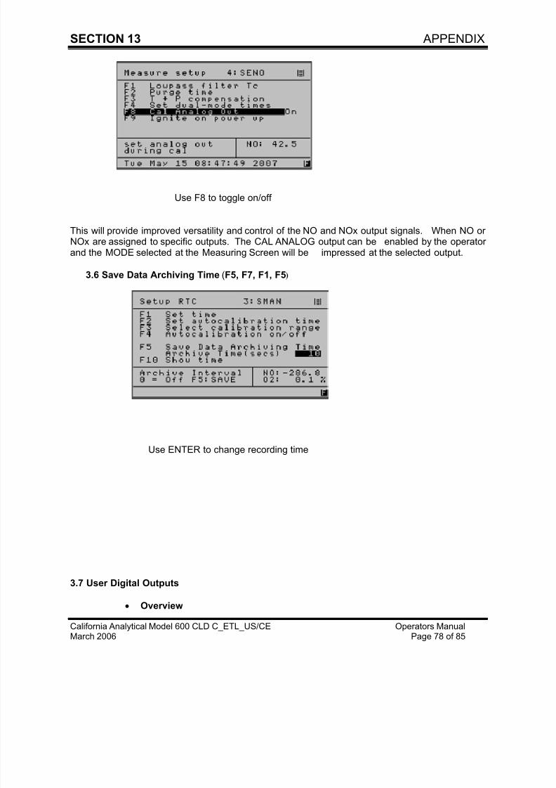
3.6 Save Data Archiving Time (F5, F7, F1, F5)
Use ENTER to change recording time
3.7 User Digital Outputs
• Overview
7/23/2019 600 Series Cld Ops Manual 1213
http://slidepdf.com/reader/full/600-series-cld-ops-manual-1213 88/116
SECTION 13 APPENDIX
California Analytical Model 600 CLD C_ETL_US/CE Operators ManualMarch 2006 Page 79 of 85
The 600 HCD Series of instruments have 15 solid state, optically coupled, isolated relaysthat can be programmed by the operator to indicate the status of numerous digitalconditions
The available digital signals consist of a SERVICE group, that can be used to externally
monitor a number of conditions to aid in preventative maintenance and diagnostics.
A second STATUS group, is provided and is used to define the operation of the instrumentsuch as Spanning, Zeroing, Calibrating and the current Range (1, 2, 3, 4, AUTO) etc.
The individual output signals can be operator selected and set to a HOLD or CLEARmode.
In the HOLD mode an activated signal is retained until the operator returns to the Digital
Output Screen and selects the appropriate output signal and performs a manual CLEAR.
In the CLEAR mode the signal will automatically change state when the microprocessor
detects that the noted condition no longer exists.
The operator can select from the following the desired SERVICE or STATUS items that areto be digitally monitored.
• SERVICE
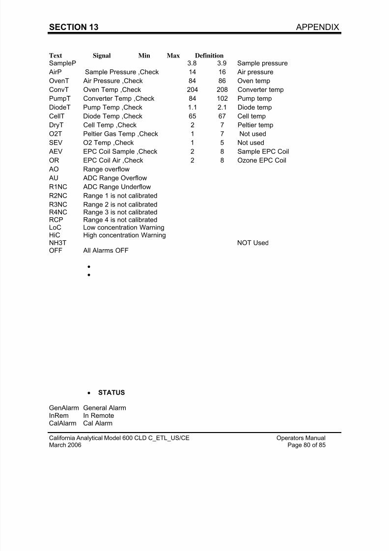
7/23/2019 600 Series Cld Ops Manual 1213
http://slidepdf.com/reader/full/600-series-cld-ops-manual-1213 89/116
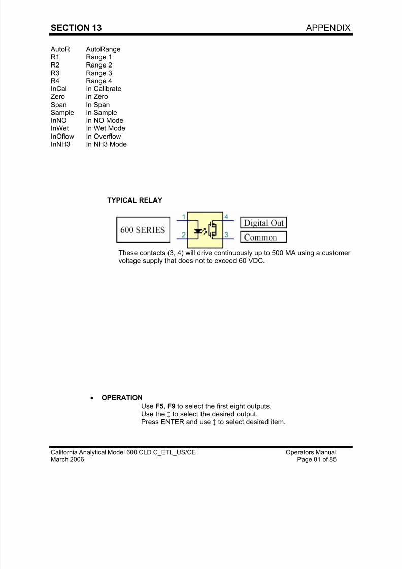
7/23/2019 600 Series Cld Ops Manual 1213
http://slidepdf.com/reader/full/600-series-cld-ops-manual-1213 90/116
SECTION 13 APPENDIX
California Analytical Model 600 CLD C_ETL_US/CE Operators ManualMarch 2006 Page 81 of 85
AutoR AutoRangeR1 Range 1R2 Range 2R3 Range 3R4 Range 4InCal In Calibrate
Zero In ZeroSpan In SpanSample In SampleInNO In NO ModeInWet In Wet ModeInOflow In OverflowInNH3 In NH3 Mode
TYPICAL RELAY
These contacts (3, 4) will drive continuously up to 500 MA using a customervoltage supply that does not to exceed 60 VDC.
• OPERATION
Use F5, F9 to select the first eight outputs.Use the ↕ to select the desired output.Press ENTER and use ↕ to select desired item.
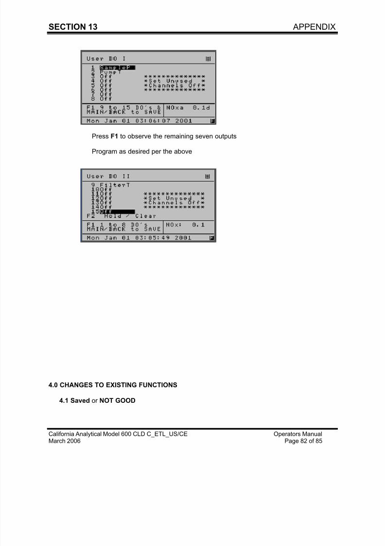
7/23/2019 600 Series Cld Ops Manual 1213
http://slidepdf.com/reader/full/600-series-cld-ops-manual-1213 91/116
SECTION 13 APPENDIX
California Analytical Model 600 CLD C_ETL_US/CE Operators ManualMarch 2006 Page 82 of 85
Press F1 to observe the remaining seven outputs
Program as desired per the above
4.0 CHANGES TO EXISTING FUNCTIONS
4.1 Saved or NOT GOOD
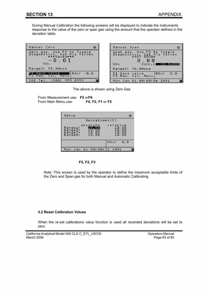
7/23/2019 600 Series Cld Ops Manual 1213
http://slidepdf.com/reader/full/600-series-cld-ops-manual-1213 92/116
SECTION 13 APPENDIX
California Analytical Model 600 CLD C_ETL_US/CE Operators ManualMarch 2006 Page 83 of 85
During Manual Calibration the following screens will be displayed to indicate the instrumentsresponse to the value of the zero or span gas using the amount that the operator defined in thedeviation table.
The above is shown using Zero Gas
From Measurement use: F5 or F6From Main Menu use: F4, F2, F1 or F2
F5, F2, F3
Note :This screen is used by the operator to define the maximum acceptable limits ofthe Zero and Span gas for both Manual and Automatic Calibrating.
4.2 Reset Calibration Values
When the re-set calibrations value function is used all recorded deviations will be set tozero
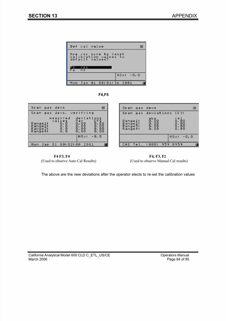
7/23/2019 600 Series Cld Ops Manual 1213
http://slidepdf.com/reader/full/600-series-cld-ops-manual-1213 93/116
SECTION 13 APPENDIX
California Analytical Model 600 CLD C_ETL_US/CE Operators ManualMarch 2006 Page 84 of 85
F4,F5
F4 F3, F4 F4, F3, F2
(Used to observe Auto Cal Results) (Used to observe Manual Cal results)
The above are the new deviations after the operator elects to re-set the calibration values
7/23/2019 600 Series Cld Ops Manual 1213
http://slidepdf.com/reader/full/600-series-cld-ops-manual-1213 94/116
ADDENDUM
California Analytical InstrumentsModel 600 CLD Operators ManualJanuary 10, 2011 Page 1 of 24
TABLE OF CONTENTS
ADDENDUM
STARTING AFTER JUNE, 2007
Section Title Page
1.0. Introduction -------------------------------------------------------------------------------------
2.0. Operation of Measurement Keys -----------------------------------------------------------------
2.1. Over Range --------------------------------------------------------------------------------
2.2. Diagnostics----------------------------------------------------------------------------------
2.3. Zero ------------------------------------------------------------------------------------------
2.4. Span -----------------------------------------------------------------------------------------
2.5. Range Limits-------------------------------------------------------------------------------
2.6. Span Values -------------------------------------------------------------------------------2.7. Outputs -------------------------------------------------------------------------------------
3.0 New Functions ---------------------------------------------------------------------------------------------
3.1. Auto Start Up ------------------------------------------------------------------------------
3.2. Alarms On/Off -----------------------------------------------------------------------------
3.3. Offset & Gain ------------------------------------------------------------------------------
3.4. Calibrate The Analog Outputs ---------------------------------------------------------
3.5. Save Data Archiving Time -------------------------------------------------------------
TABLE A ------------------------------------------------------------------------------
3.6. User Digital Outputs ---------------------------------------------------------------------
TABLE B -------------------------------------------------------------------------------
TABLE C-------------------------------------------------------------------------------
3.7. Cal Analog Output------------------------------------------------------------------------
4.0. Changes To Existing Functions ----------------------------------------------------------
4.1. Saved or Outside Limits ----------------------------------------------------------------
4.2. Calibration Deviations--------------------------------------------------------------------
4.3. Flow Zero or Span Gas------------------------------------------------------------------
4.4. Reset Calibration Values ---------------------------------------------------------------
TABLE D-------------------------------------------------------------------------------
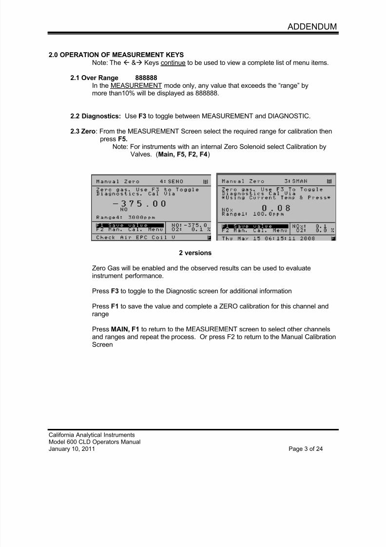
7/23/2019 600 Series Cld Ops Manual 1213
http://slidepdf.com/reader/full/600-series-cld-ops-manual-1213 95/116
ADDENDUM
California Analytical InstrumentsModel 600 CLD Operators ManualJanuary 10, 2011 Page 3 of 24
2.0 OPERATION OF MEASUREMENT KEYSNote: The & Keys continue to be used to view a complete list of menu items.
2.1 Over Range 888888In the MEASUREMENT mode only, any value that exceeds the “range” by
more than10% will be displayed as 888888.
2.2 Diagnostics: Use F3 to toggle between MEASUREMENT and DIAGNOSTIC.
2.3 Zero: From the MEASUREMENT Screen select the required range for calibration then press F5.
Note: For instruments with an internal Zero Solenoid select Calibration byValves. (Main, F5, F2, F4)
2 versions
Zero Gas will be enabled and the observed results can be used to evaluate
instrument performance.
Press F3 to toggle to the Diagnostic screen for additional information
Press F1 to save the value and complete a ZERO calibration for this channel andrange
Press MAIN, F1 to return to the MEASUREMENT screen to select other channelsand ranges and repeat the process. Or press F2 to return to the Manual CalibrationScreen
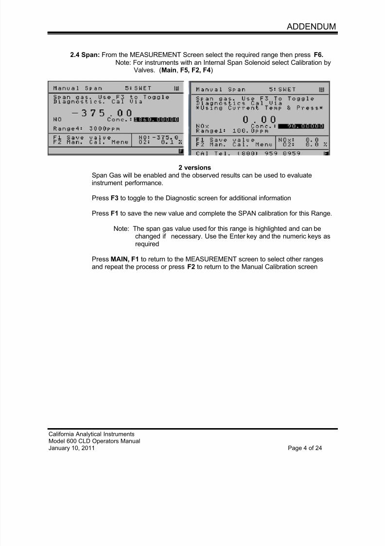
7/23/2019 600 Series Cld Ops Manual 1213
http://slidepdf.com/reader/full/600-series-cld-ops-manual-1213 96/116
ADDENDUM
California Analytical InstrumentsModel 600 CLD Operators ManualJanuary 10, 2011 Page 4 of 24
2.4 Span: From the MEASUREMENT Screen select the required range then press F6.Note: For instruments with an Internal Span Solenoid select Calibration by
Valves. (Main, F5, F2, F4)
2 versionsSpan Gas will be enabled and the observed results can be used to evaluate
instrument performance.
Press F3 to toggle to the Diagnostic screen for additional information
Press F1 to save the new value and complete the SPAN calibration for this Range.
Note: The span gas value used for this range is highlighted and can bechanged if necessary. Use the Enter key and the numeric keys asrequired
Press MAIN, F1 to return to the MEASUREMENT screen to select other rangesand repeat the process or press F2 to return to the Manual Calibration screen
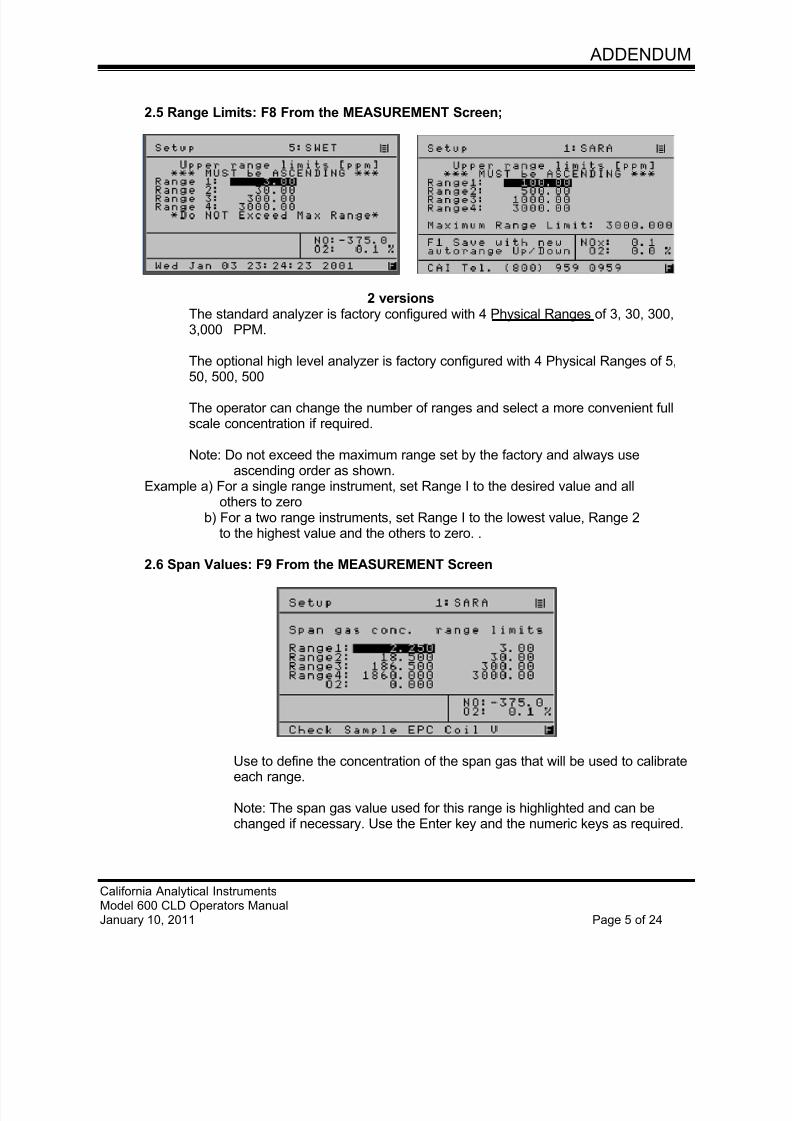
7/23/2019 600 Series Cld Ops Manual 1213
http://slidepdf.com/reader/full/600-series-cld-ops-manual-1213 97/116
ADDENDUM
California Analytical InstrumentsModel 600 CLD Operators ManualJanuary 10, 2011 Page 5 of 24
2.5 Range Limits: F8 From the MEASUREMENT Screen;
2 versionsThe standard analyzer is factory configured with 4 Physical Ranges of 3, 30, 300,3,000 PPM.
The optional high level analyzer is factory configured with 4 Physical Ranges of 5,
50, 500, 500
The operator can change the number of ranges and select a more convenient fullscale concentration if required.
Note: Do not exceed the maximum range set by the factory and always useascending order as shown.
Example a) For a single range instrument, set Range I to the desired value and allothers to zero
b) For a two range instruments, set Range I to the lowest value, Range 2to the highest value and the others to zero. .
2.6 Span Values: F9 From the MEASUREMENT Screen
Use to define the concentration of the span gas that will be used to calibrateeach range.
Note: The span gas value used for this range is highlighted and can bechanged if necessary. Use the Enter key and the numeric keys as required.
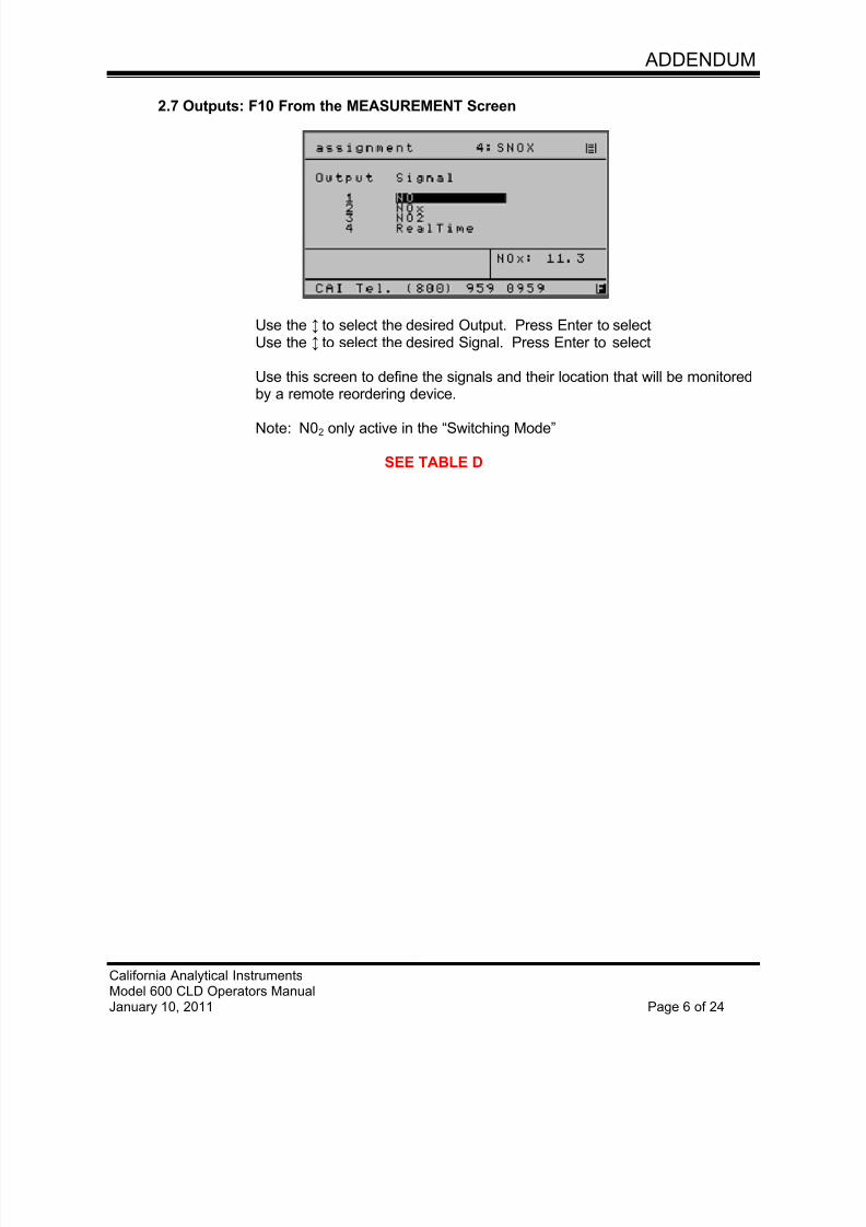
7/23/2019 600 Series Cld Ops Manual 1213
http://slidepdf.com/reader/full/600-series-cld-ops-manual-1213 98/116
ADDENDUM
California Analytical InstrumentsModel 600 CLD Operators ManualJanuary 10, 2011 Page 6 of 24
2.7 Outputs: F10 From the MEASUREMENT Screen
Use the ↕ to select the desired Output. Press Enter to select Use the ↕ to select the desired Signal. Press Enter to select
Use this screen to define the signals and their location that will be monitoredby a remote reordering device.
Note: N02 only active in the “Switching Mode”
SEE TABLE D
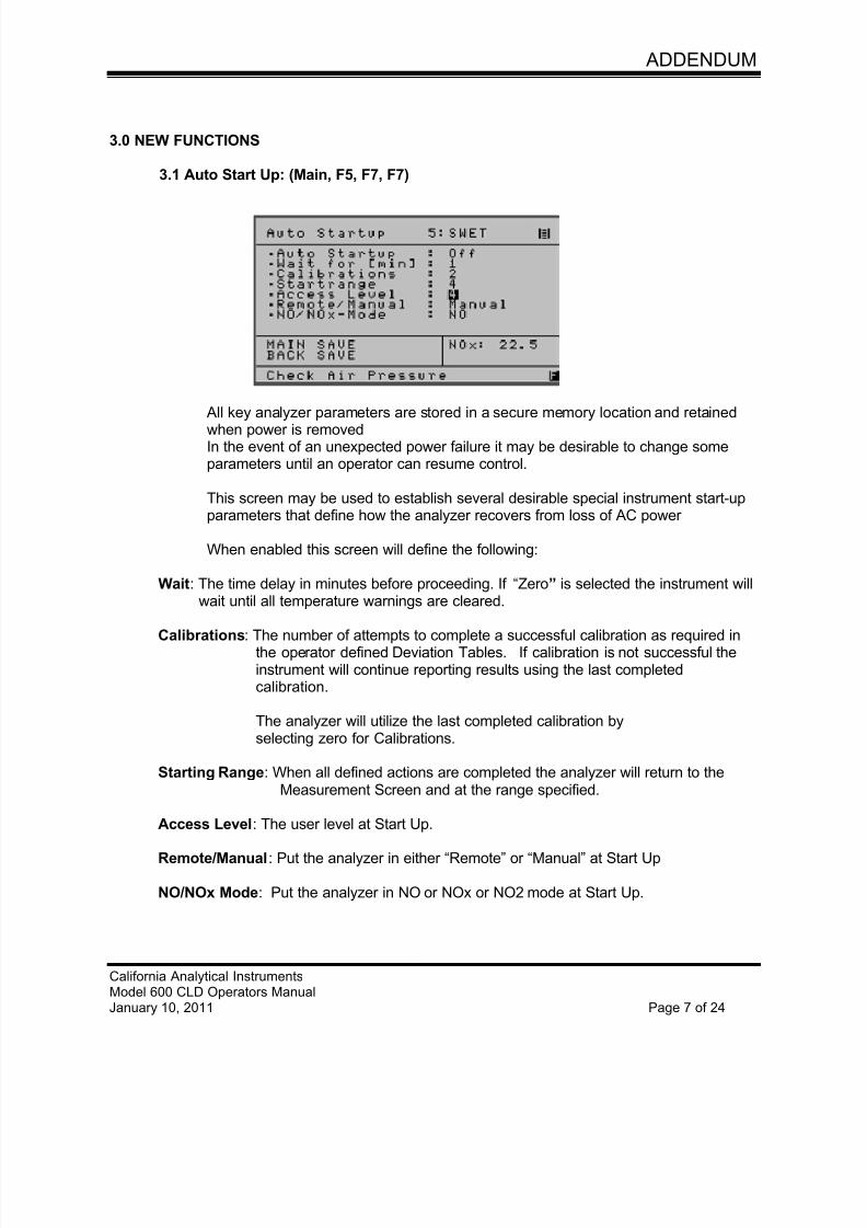
7/23/2019 600 Series Cld Ops Manual 1213
http://slidepdf.com/reader/full/600-series-cld-ops-manual-1213 99/116
ADDENDUM
California Analytical InstrumentsModel 600 CLD Operators ManualJanuary 10, 2011 Page 7 of 24
3.0 NEW FUNCTIONS
3.1 Auto Start Up: (Main, F5, F7, F7)
All key analyzer parameters are stored in a secure memory location and retainedwhen power is removedIn the event of an unexpected power failure it may be desirable to change someparameters until an operator can resume control.
This screen may be used to establish several desirable special instrument start-upparameters that define how the analyzer recovers from loss of AC power
When enabled this screen will define the following:
Wait: The time delay in minutes before proceeding. If “Zero” is selected the instrument willwait until all temperature warnings are cleared.
Calibrations: The number of attempts to complete a successful calibration as required inthe operator defined Deviation Tables. If calibration is not successful theinstrument will continue reporting results using the last completedcalibration.
The analyzer will utilize the last completed calibration byselecting zero for Calibrations.
Starting Range: When all defined actions are completed the analyzer will return to theMeasurement Screen and at the range specified.
Access Level: The user level at Start Up.
Remote/Manual: Put the analyzer in either “Remote” or “Manual” at Start Up
NO/NOx Mode: Put the analyzer in NO or NOx or NO2 mode at Start Up.
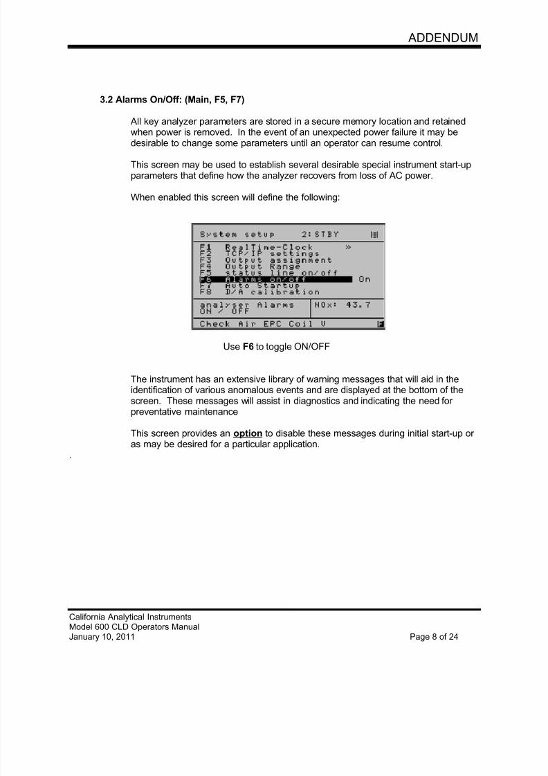
7/23/2019 600 Series Cld Ops Manual 1213
http://slidepdf.com/reader/full/600-series-cld-ops-manual-1213 100/116
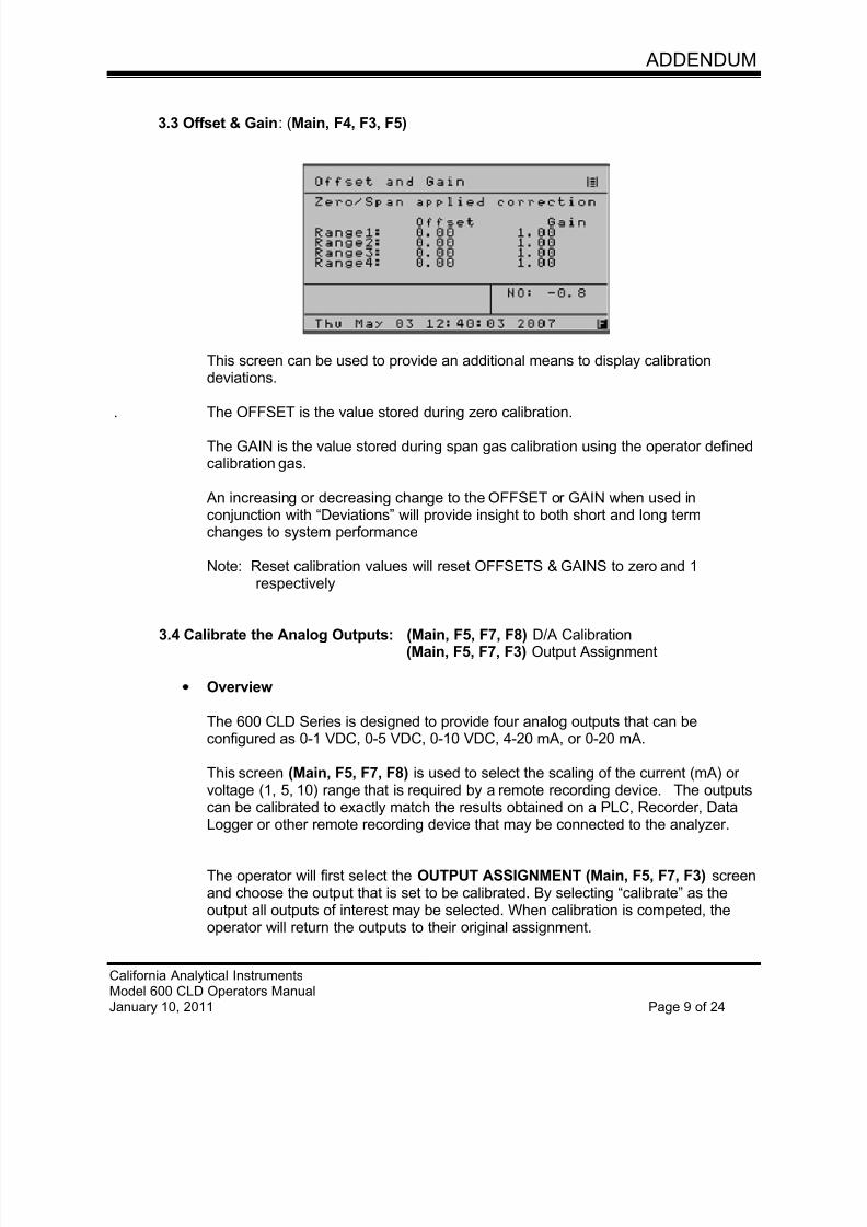
7/23/2019 600 Series Cld Ops Manual 1213
http://slidepdf.com/reader/full/600-series-cld-ops-manual-1213 101/116
ADDENDUM
California Analytical InstrumentsModel 600 CLD Operators ManualJanuary 10, 2011 Page 9 of 24
3.3 Offset & Gain: (Main, F4, F3, F5)
This screen can be used to provide an additional means to display calibrationdeviations.
. The OFFSET is the value stored during zero calibration.
The GAIN is the value stored during span gas calibration using the operator definedcalibration gas.
An increasing or decreasing change to the OFFSET or GAIN when used inconjunction with “Deviations” will provide insight to both short and long termchanges to system performance
Note: Reset calibration values will reset OFFSETS & GAINS to zero and 1respectively
3.4 Calibrate the Analog Outputs: (Main, F5, F7, F8) D/A Calibration(Main, F5, F7, F3) Output Assignment
Overview
The 600 CLD Series is designed to provide four analog outputs that can beconfigured as 0-1 VDC, 0-5 VDC, 0-10 VDC, 4-20 mA, or 0-20 mA.
This screen (Main, F5, F7, F8) is used to select the scaling of the current (mA) orvoltage (1, 5, 10) range that is required by a remote recording device. The outputscan be calibrated to exactly match the results obtained on a PLC, Recorder, Data
Logger or other remote recording device that may be connected to the analyzer.
The operator will first select the OUTPUT ASSIGNMENT (Main, F5, F7, F3) screenand choose the output that is set to be calibrated. By selecting “calibrate” as theoutput all outputs of interest may be selected. When calibration is competed, theoperator will return the outputs to their original assignment.
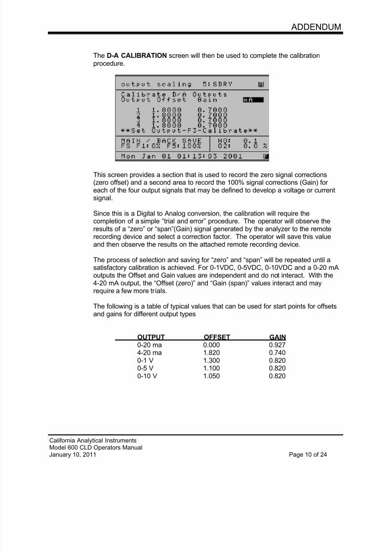
7/23/2019 600 Series Cld Ops Manual 1213
http://slidepdf.com/reader/full/600-series-cld-ops-manual-1213 102/116
ADDENDUM
California Analytical InstrumentsModel 600 CLD Operators ManualJanuary 10, 2011 Page 10 of 24
The D-A CALIBRATION screen will then be used to complete the calibrationprocedure.
This screen provides a section that is used to record the zero signal corrections(zero offset) and a second area to record the 100% signal corrections (Gain) foreach of the four output signals that may be defined to develop a voltage or currentsignal.
Since this is a Digital to Analog conversion, the calibration will require thecompletion of a simple “trial and error” procedure. The operator will observe theresults of a “zero” or “span”(Gain) signal generated by the analyzer to the remoterecording device and select a correction factor. The operator will save this valueand then observe the results on the attached remote recording device.
The process of selection and saving for “zero” and “span” will be repeated until asatisfactory calibration is achieved. For 0-1VDC, 0-5VDC, 0-10VDC and a 0-20 mAoutputs the Offset and Gain values are independent and do not interact. With the4-20 mA output, the “Offset (zero)” and “Gain (span)” values interact and mayrequire a few more trials.
The following is a table of typical values that can be used for start points for offsetsand gains for different output types
OUTPUT OFFSET GAIN0-20 ma 0.000 0.9274-20 ma 1.820 0.7400-1 V 1.300 0.8200-5 V 1.100 0.820
0-10 V 1.050 0.820
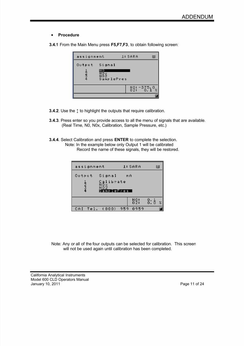
7/23/2019 600 Series Cld Ops Manual 1213
http://slidepdf.com/reader/full/600-series-cld-ops-manual-1213 103/116
ADDENDUM
California Analytical InstrumentsModel 600 CLD Operators ManualJanuary 10, 2011 Page 11 of 24
Procedure
3.4.1 From the Main Menu press F5,F7,F3, to obtain following screen:
3.4.2. Use the ↕ to highlight the outputs that require calibration.
3.4.3. Press enter so you provide access to all the menu of signals that are available.(Real Time, N0, N0x, Calibration, Sample Pressure, etc.)
3.4.4. Select Calibration and press ENTER to complete the selection.Note: In the example below only Output 1 will be calibrated
Record the name of these signals, they will be restored.
Note: Any or all of the four outputs can be selected for calibration. This screenwill not be used again until calibration has been completed.
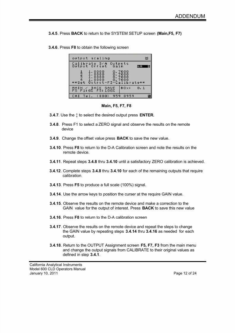
7/23/2019 600 Series Cld Ops Manual 1213
http://slidepdf.com/reader/full/600-series-cld-ops-manual-1213 104/116
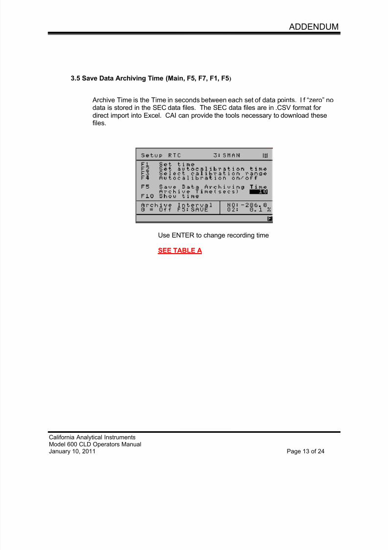
7/23/2019 600 Series Cld Ops Manual 1213
http://slidepdf.com/reader/full/600-series-cld-ops-manual-1213 105/116
ADDENDUM
California Analytical InstrumentsModel 600 CLD Operators ManualJanuary 10, 2011 Page 13 of 24
3.5 Save Data Archiving Time (Main, F5, F7, F1, F5)
Archive Time is the Time in seconds between each set of data points. If “zero” nodata is stored in the SEC data files. The SEC data files are in .CSV format fordirect import into Excel. CAI can provide the tools necessary to download thesefiles.
Use ENTER to change recording time
SEE TABLE A
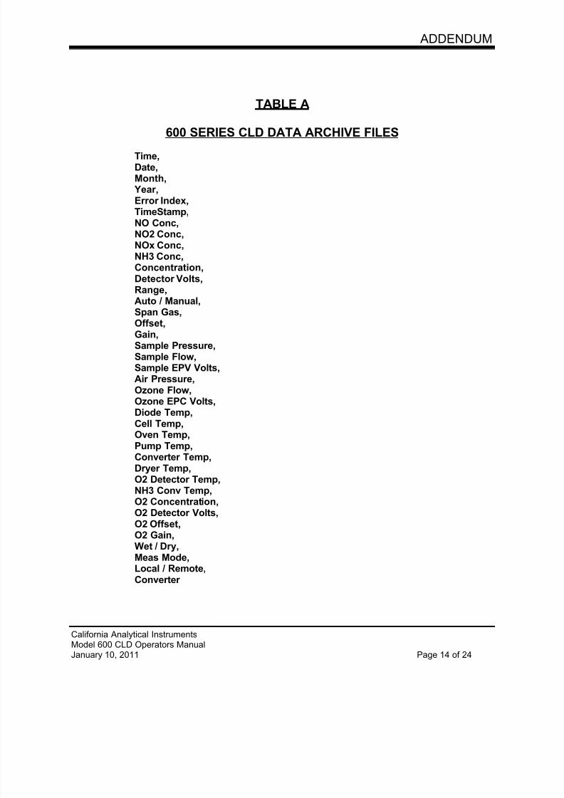
7/23/2019 600 Series Cld Ops Manual 1213
http://slidepdf.com/reader/full/600-series-cld-ops-manual-1213 106/116
ADDENDUM
California Analytical InstrumentsModel 600 CLD Operators ManualJanuary 10, 2011 Page 14 of 24
TABLE A
600 SERIES CLD DATA ARCHIVE FILES
Time,Date,Month,
Year,Error Index,TimeStamp,NO Conc,NO2 Conc,NOx Conc,NH3 Conc,
Concentration,Detector Volts,Range,Auto / Manual,Span Gas,Offset,Gain,Sample Pressure,Sample Flow,Sample EPV Volts,Air Pressure,Ozone Flow,
Ozone EPC Volts,Diode Temp,Cell Temp,Oven Temp,Pump Temp,Converter Temp,Dryer Temp,O2 Detector Temp,NH3 Conv Temp,O2 Concentration,O2 Detector Volts,O2 Offset,
O2 Gain,Wet / Dry,Meas Mode,Local / Remote,Converter
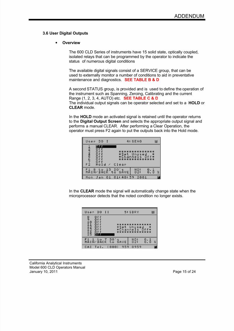
7/23/2019 600 Series Cld Ops Manual 1213
http://slidepdf.com/reader/full/600-series-cld-ops-manual-1213 107/116
ADDENDUM
California Analytical InstrumentsModel 600 CLD Operators ManualJanuary 10, 2011 Page 15 of 24
3.6 User Digital Outputs
Overview
The 600 CLD Series of instruments have 15 solid state, optically coupled,
isolated relays that can be programmed by the operator to indicate thestatus of numerous digital conditions
The available digital signals consist of a SERVICE group, that can beused to externally monitor a number of conditions to aid in preventativemaintenance and diagnostics. SEE TABLE B & D
A second STATUS group, is provided and is used to define the operation ofthe instrument such as Spanning, Zeroing, Calibrating and the currentRange (1, 2, 3, 4, AUTO) etc. SEE TABLE C & D The individual output signals can be operator selected and set to a HOLD orCLEAR mode.
In the HOLD mode an activated signal is retained until the operator returnsto the Digital Output Screen and selects the appropriate output signal andperforms a manual CLEAR. After performing a Clear Operation, theoperator must press F2 again to put the outputs back into the Hold mode.
In the CLEAR mode the signal will automatically change state when themicroprocessor detects that the noted condition no longer exists.
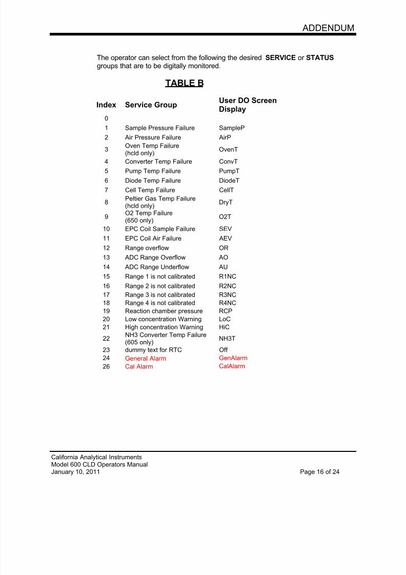
7/23/2019 600 Series Cld Ops Manual 1213
http://slidepdf.com/reader/full/600-series-cld-ops-manual-1213 108/116
ADDENDUM
California Analytical InstrumentsModel 600 CLD Operators ManualJanuary 10, 2011 Page 16 of 24
The operator can select from the following the desired SERVICE or STATUSgroups that are to be digitally monitored.
TABLE B
Index Service GroupUser DO ScreenDisplay
0
1 Sample Pressure Failure SampleP
2 Air Pressure Failure AirP
3Oven Temp Failure(hcld only)
OvenT
4 Converter Temp Failure ConvT
5 Pump Temp Failure PumpT
6 Diode Temp Failure DiodeT
7 Cell Temp Failure CellT
8Peltier Gas Temp Failure(hcld only)
DryT
9O2 Temp Failure(650 only)
O2T
10 EPC Coil Sample Failure SEV
11 EPC Coil Air Failure AEV
12 Range overflow OR
13 ADC Range Overflow AO
14 ADC Range Underflow AU
15 Range 1 is not calibrated R1NC
16 Range 2 is not calibrated R2NC
17 Range 3 is not calibrated R3NC
18 Range 4 is not calibrated R4NC
19 Reaction chamber pressure RCP
20 Low concentration Warning LoC
21 High concentration Warning HiC
22NH3 Converter Temp Failure(605 only)
NH3T
23 dummy text for RTC Off
24 General Alarm GenAlarm
26 Cal Alarm CalAlarm
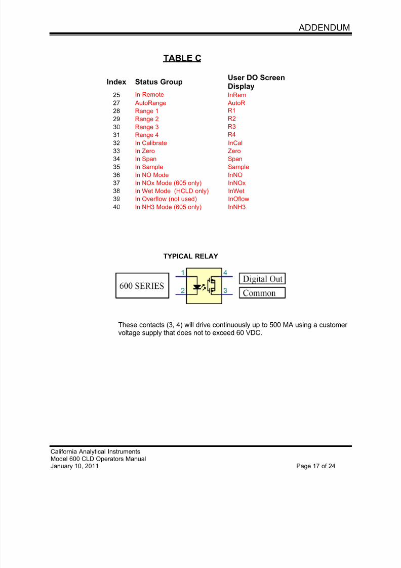
7/23/2019 600 Series Cld Ops Manual 1213
http://slidepdf.com/reader/full/600-series-cld-ops-manual-1213 109/116
ADDENDUM
California Analytical InstrumentsModel 600 CLD Operators ManualJanuary 10, 2011 Page 17 of 24
TABLE C
Index Status GroupUser DO ScreenDisplay
25 In Remote InRem27 AutoRange AutoR
28 Range 1 R1
29 Range 2 R2
30 Range 3 R3
31 Range 4 R4
32 In Calibrate InCal
33 In Zero Zero
34 In Span Span
35 In Sample Sample
36 In NO Mode InNO
37 In NOx Mode (605 only) InNOx
38 In Wet Mode (HCLD only) InWet39 In Overflow (not used) InOflow
40 In NH3 Mode (605 only) InNH3
TYPICAL RELAY
These contacts (3, 4) will drive continuously up to 500 MA using a customervoltage supply that does not to exceed 60 VDC.
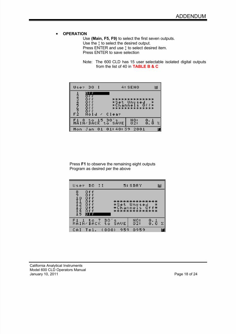
7/23/2019 600 Series Cld Ops Manual 1213
http://slidepdf.com/reader/full/600-series-cld-ops-manual-1213 110/116
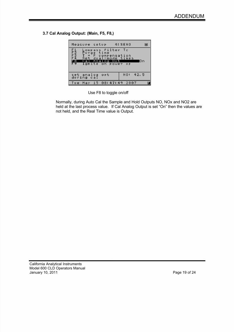
7/23/2019 600 Series Cld Ops Manual 1213
http://slidepdf.com/reader/full/600-series-cld-ops-manual-1213 111/116
ADDENDUM
California Analytical InstrumentsModel 600 CLD Operators ManualJanuary 10, 2011 Page 19 of 24
3.7 Cal Analog Output: (Main, F5, F8,)
Use F8 to toggle on/off
Normally, during Auto Cal the Sample and Hold Outputs NO, NOx and NO2 areheld at the last process value. If Cal Analog Output is set “On” then the values are
not held, and the Real Time value is Output.
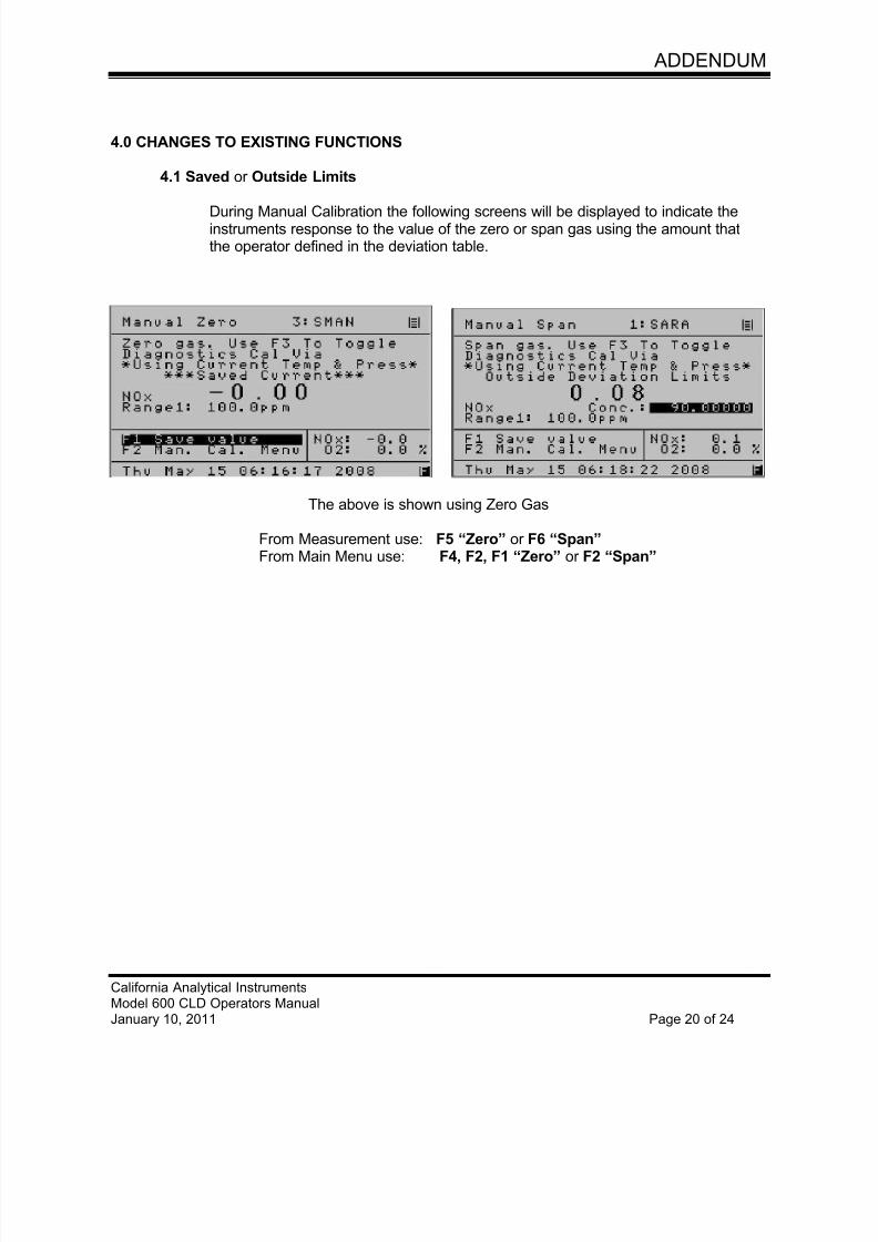
7/23/2019 600 Series Cld Ops Manual 1213
http://slidepdf.com/reader/full/600-series-cld-ops-manual-1213 112/116
ADDENDUM
California Analytical InstrumentsModel 600 CLD Operators ManualJanuary 10, 2011 Page 20 of 24
4.0 CHANGES TO EXISTING FUNCTIONS
4.1 Saved or Outside Limits
During Manual Calibration the following screens will be displayed to indicate theinstruments response to the value of the zero or span gas using the amount thatthe operator defined in the deviation table.
The above is shown using Zero Gas
From Measurement use: F5 “Zero” or F6 “Span” From Main Menu use: F4, F2, F1 “Zero” or F2 “Span”
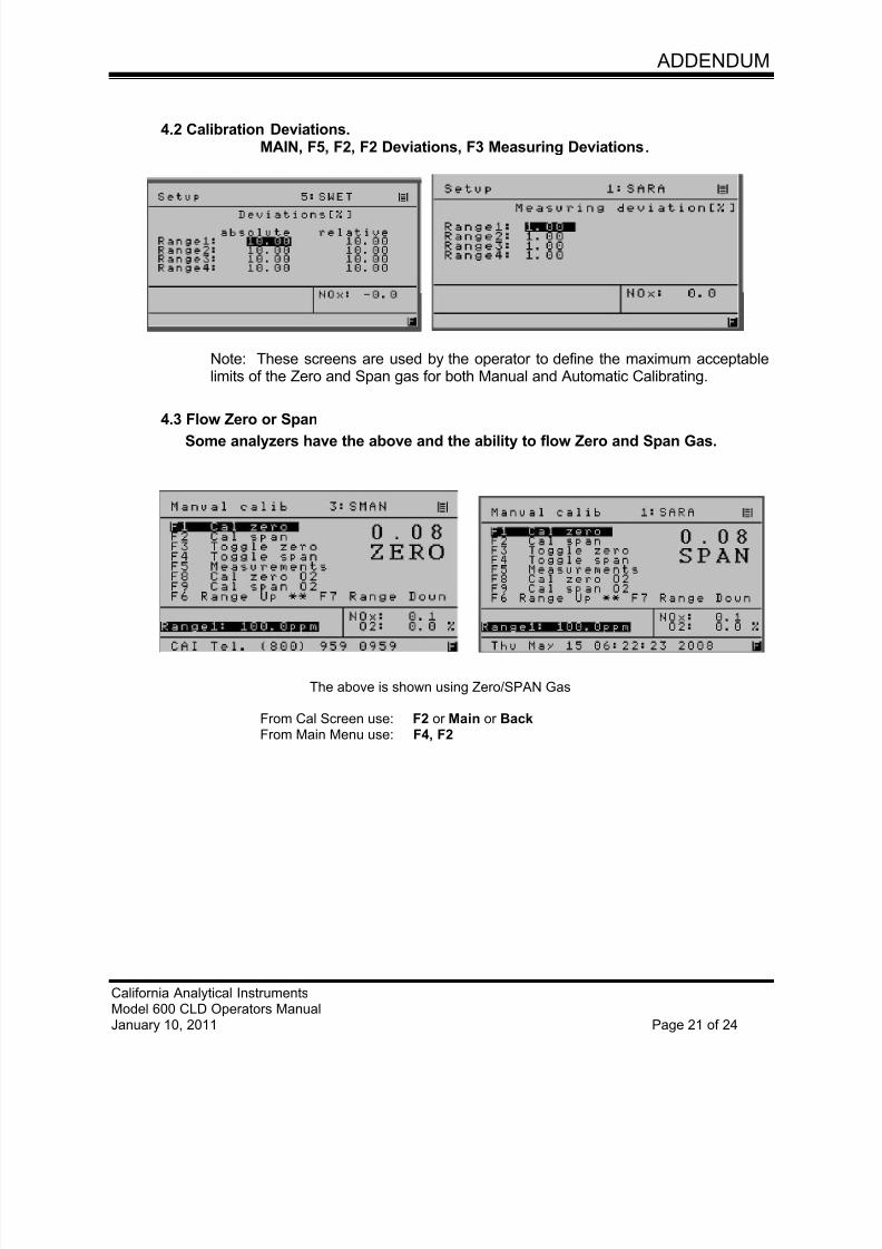
7/23/2019 600 Series Cld Ops Manual 1213
http://slidepdf.com/reader/full/600-series-cld-ops-manual-1213 113/116
ADDENDUM
California Analytical InstrumentsModel 600 CLD Operators ManualJanuary 10, 2011 Page 21 of 24
4.2 Calibration Deviations.MAIN, F5, F2, F2 Deviations, F3 Measuring Deviations.
Note: These screens are used by the operator to define the maximum acceptablelimits of the Zero and Span gas for both Manual and Automatic Calibrating.
4.3 Flow Zero or SpanSome analyzers have the above and the ability to flow Zero and Span Gas.
The above is shown using Zero/SPAN Gas
From Cal Screen use: F2 or Main or BackFrom Main Menu use: F4, F2
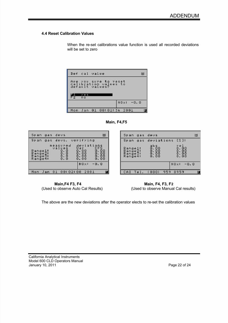
7/23/2019 600 Series Cld Ops Manual 1213
http://slidepdf.com/reader/full/600-series-cld-ops-manual-1213 114/116
ADDENDUM
California Analytical InstrumentsModel 600 CLD Operators ManualJanuary 10, 2011 Page 22 of 24
4.4 Reset Calibration Values
When the re-set calibrations value function is used all recorded deviationswill be set to zero
Main, F4,F5
Main,F4 F3, F4 Main, F4, F3, F2
(Used to observe Auto Cal Results) (Used to observe Manual Cal results)
The above are the new deviations after the operator elects to re-set the calibration values
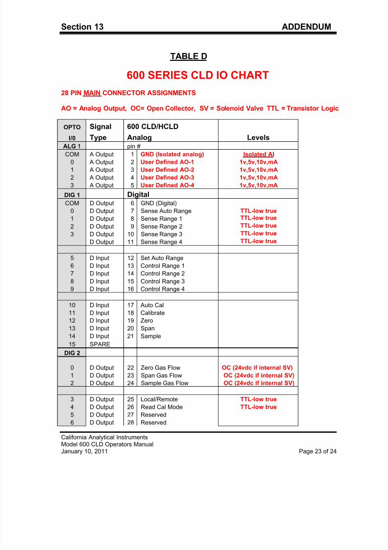
7/23/2019 600 Series Cld Ops Manual 1213
http://slidepdf.com/reader/full/600-series-cld-ops-manual-1213 115/116
Section 13 ADDENDUM
California Analytical InstrumentsModel 600 CLD Operators ManualJanuary 10, 2011 Page 23 of 24
TABLE D
600 SERIES CLD IO CHART
28 PIN MAIN CONNECTOR ASSIGNMENTS
AO = Analog Output, OC= Open Collector, SV = Solenoid Valve TTL = Transistor Logic
OPTO Signal 600 CLD/HCLD
I/0 Type Analog LevelsALG 1 pin #
COM A Output 1 GND (Isolated analog) Isolated AI
0 A Output 2 User Defined AO-1 1v,5v,10v,mA
1 A Output 3 User Defined AO-2 1v,5v,10v,mA
2 A Output 4 User Defined AO-3 1v,5v,10v,mA
3 A Output 5 User Defined AO-4 1v,5v,10v,mA
DIG 1 DigitalCOM D Output 6 GND (Digital)
0 D Output 7 Sense Auto Range TTL-low true
1 D Output 8 Sense Range 1 TTL-low true
2 D Output 9 Sense Range 2 TTL-low true
3 D Output 10 Sense Range 3 TTL-low true
D Output 11 Sense Range 4 TTL-low true
5 D Input 12 Set Auto Range
6 D Input 13 Control Range 1
7 D Input 14 Control Range 2
8 D Input 15 Control Range 3
9 D Input 16 Control Range 4
10 D Input 17 Auto Cal
11 D Input 18 Calibrate
12 D Input 19 Zero
13 D Input 20 Span
14 D Input 21 Sample
15 SPARE
DIG 2
0 D Output 22 Zero Gas Flow OC (24vdc if internal SV)
1 D Output 23 Span Gas Flow OC (24vdc if internal SV)
2 D Output 24 Sample Gas Flow OC (24vdc if internal SV)
3 D Output 25 Local/Remote TTL-low true
4 D Output 26 Read Cal Mode TTL-low true
5 D Output 27 Reserved
6 D Output 28 Reserved
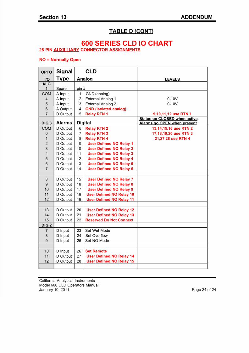
7/23/2019 600 Series Cld Ops Manual 1213
http://slidepdf.com/reader/full/600-series-cld-ops-manual-1213 116/116
Section 13 ADDENDUM
TABLE D (CONT)
600 SERIES CLD IO CHART28 PIN AUXILLIARY CONNECTOR ASSIGNMENTS
NO = Normally Open
OPTO Signal CLD
I/O Type Analog LEVELS
ALG1 Spare pin #
COM A Input 1 GND (analog)
4 A Input 2 External Analog 1 0-10V
5 A Input 3 External Analog 2 0-10V
6 A Output 4 GND (Isolated analog)
7 D Output 5 Relay RTN 1 9,10,11,12 use RTN 1
DIG 3 Alarms DigitalStatus go CLOSED when activeAlarms go OPEN when present
COM D Output 6 Relay RTN 2 13,14,15,16 use RTN 2
0 D Output 7 Relay RTN 3 17,18,19,20 use RTN 3
1 D Output 8 Relay RTN 4 21,27,28 use RTN 4
2 D Output 9 User Defined NO Relay 1
3 D Output 10 User Defined NO Relay 2
4 D Output 11 User Defined NO Relay 3
5 D Output 12 User Defined NO Relay 4
6 D Output 13 User Defined NO Relay 5
7 D Output 14 User Defined NO Relay 6
8 D Output 15 User Defined NO Relay 79 D Output 16 User Defined NO Relay 8
10 D Output 17 User Defined NO Relay 9
11 D Output 18 User Defined NO Relay 10
12 D O t t 19 U D fi d NO R l 11